GUJARAT ENERGY TRANSMISSION CORPORATION LTD. Sardar … Office/041110/1_TECH... · ... \11SJH\ALL...
41
GETCO/E/TS-POWER CABLE/R0 DT 09-03-2009 F:\11SJH\ALL FOLDERS\SPECIFICATIONS POWER CABLES & LAYING\220KV XLPE\220KV CABLE SPECSFINAL.doc 1 GUJARAT ENERGY TRANSMISSION CORPORATION LTD. Sardar Patel Vidyut Bhavan, Race Course, Vadodara: 390 007 TECHNICAL SPECIFICATION FOR SUPPLY 220KV ,1C,XLPE POWER CABLE FOR TRANSMISSION LINES & SUB-STATIONS GETCO/ENGG/TECH. SPECI. –POWER CABLE/ REV-0 DT. 09/03/2009
Transcript of GUJARAT ENERGY TRANSMISSION CORPORATION LTD. Sardar … Office/041110/1_TECH... · ... \11SJH\ALL...

GETCO/E/TS-POWER CABLE/R0 DT 09-03-2009
F:\11SJH\ALL FOLDERS\SPECIFICATIONS POWER CABLES & LAYING\220KV XLPE\220KV CABLE SPECSFINAL.doc
1
GUJARAT ENERGY TRANSMISSION CORPORATION LTD.
Sardar Patel Vidyut Bhavan, Race Course, Vadodara: 390 007
TECHNICAL SPECIFICATIONFOR
SUPPLY 220KV ,1C,XLPE POWER CABLE
FORTRANSMISSION LINES
&SUB-STATIONS
GETCO/ENGG/TECH. SPECI. –POWER CABLE/ REV-0 DT. 09/03/2009

GETCO/E/TS-POWER CABLE/R0 DT 09-03-2009
F:\11SJH\ALL FOLDERS\SPECIFICATIONS POWER CABLES & LAYING\220KV XLPE\220KV CABLE SPECSFINAL.doc
2
SPECIAL INSTRUCTIONS TO BIDDER
Please read following instructions carefully before submitting your bid.
1. All the drawings, i.e. elevation, side view, plan, cross sectional view etc., in AutoCAD format and manuals in PDF format, for offered item shall be submitted. Also the hard copies as per specification shall be submitted.
2. The bidder shall submit Quality Assurance Plan for
manufacturing process and Field Quality Plan with the technical bid.
3. The bidder shall have to submit all the required type test
reports for the offered item. In absence of this, the evaluation shall be carried out accordingly as non-submission of type test reports.
4. The bidder must fill up all the point of GTP for offered item/s.
instead of indicating “refer drawing, or as per IS/IEC”, the exact value/s must be filled in.
5. All the points other than GTP, which are asked to confirm in
technical specifications must be submitted separately with the bid.
6. The bidder is required to impart training in view of
manufacture, assembly, erection, operation and maintenance for offered item, at his works, to the person/s identified by GETCO, in the event of an order, free of cost. The cost of logistics will be borned by GETCO.
7. Please note that the evaluation will be carried out on the
strength of content of bid only. No further correspondence will be made.
8. The bidder shall bring out all the technical deviation/s only at
the specified annexure.
9. The bidder should indicate manufacturing capacity by submitting latest updated certificate of a Chartered Engineer (CE).
GETCO/E/TS-POWER CABLE/R0 DT 09-03-2009
F:\11SJH\ALL FOLDERS\SPECIFICATIONS POWER CABLES & LAYING\220KV XLPE\220KV CABLE SPECSFINAL.doc
3
QUALIFYING REQUIREMENT DATA (For Supply)
Bidder to satisfy all the following requirements.
1) The bidder shall be Original Equipment Manufacturer (OEM). The offered equipment have to be designed, manufactured and tested as per relevant IS/IEC with latest amendments.
2) The minimum requirement of manufacturing capacity of offered type, size and rating of equipment shall be 7 times tender / bid quantity. The bidder should indicate manufacturing capacity by submitting latest updated certificate of a Chartered Engineer (CE).
3) Equipment proposed shall be of similar or higher rating and in service for a minimum period of THREE (3) years and satisfactory performance certificate in respect of this is to be available and submitted.
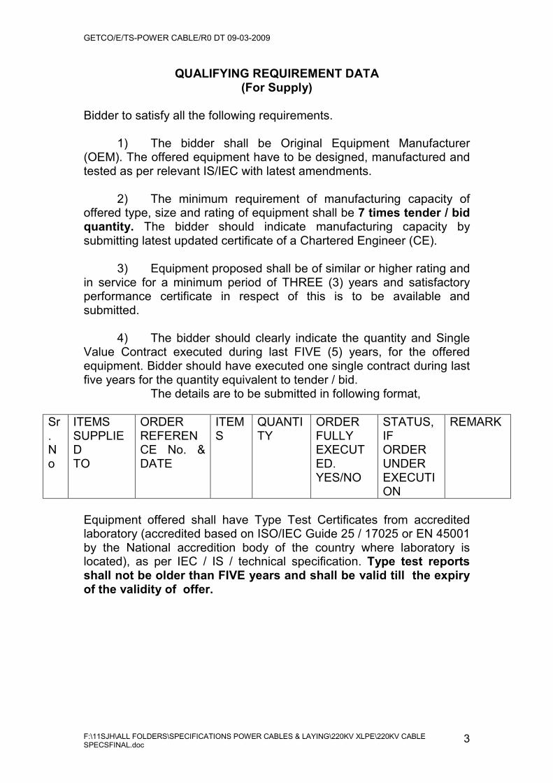
4) The bidder should clearly indicate the quantity and Single Value Contract executed during last FIVE (5) years, for the offered equipment. Bidder should have executed one single contract during last five years for the quantity equivalent to tender / bid. The details are to be submitted in following format,
Sr.No
ITEMS SUPPLIEDTO
ORDER REFERENCE No. & DATE
ITEMS
QUANTITY
ORDER FULLY EXECUTED. YES/NO
STATUS, IF ORDER UNDER EXECUTION
REMARK
Equipment offered shall have Type Test Certificates from accredited laboratory (accredited based on ISO/IEC Guide 25 / 17025 or EN 45001 by the National accredition body of the country where laboratory is located), as per IEC / IS / technical specification. Type test reports shall not be older than FIVE years and shall be valid till the expiry of the validity of offer.
GETCO/E/TS-POWER CABLE/R0 DT 09-03-2009
F:\11SJH\ALL FOLDERS\SPECIFICATIONS POWER CABLES & LAYING\220KV XLPE\220KV CABLE SPECSFINAL.doc
4
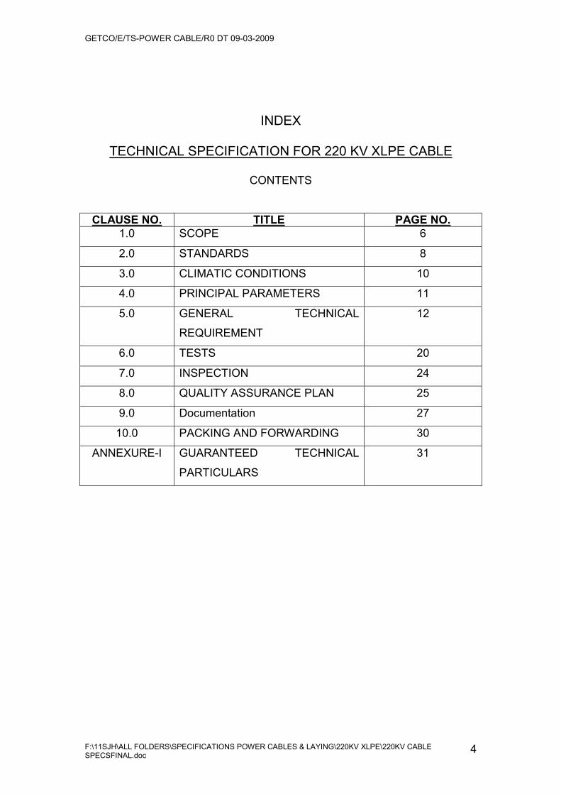
INDEX
TECHNICAL SPECIFICATION FOR 220 KV XLPE CABLE
CONTENTS
CLAUSE NO. TITLE PAGE NO.1.0 SCOPE 6
2.0 STANDARDS 8
3.0 CLIMATIC CONDITIONS 10
4.0 PRINCIPAL PARAMETERS 11
5.0 GENERAL TECHNICAL
REQUIREMENT
12
6.0 TESTS 20
7.0 INSPECTION 24
8.0 QUALITY ASSURANCE PLAN 25
9.0 Documentation 27
10.0 PACKING AND FORWARDING 30
ANNEXURE-I GUARANTEED TECHNICAL
PARTICULARS
31
GETCO/E/TS-POWER CABLE/R0 DT 09-03-2009
F:\11SJH\ALL FOLDERS\SPECIFICATIONS POWER CABLES & LAYING\220KV XLPE\220KV CABLE SPECSFINAL.doc
5
TECHNICAL SPECIFICATION
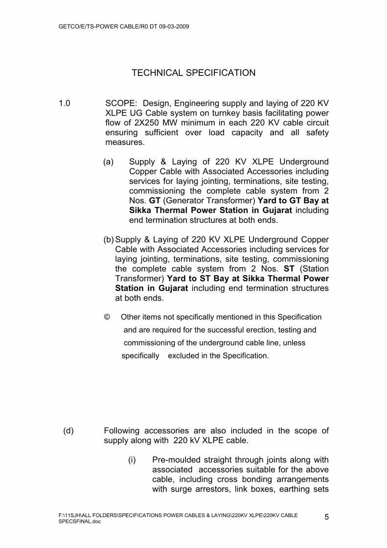
1.0 SCOPE: Design, Engineering supply and laying of 220 KV XLPE UG Cable system on turnkey basis facilitating power flow of 2X250 MW minimum in each 220 KV cable circuit ensuring sufficient over load capacity and all safety measures.
(a) Supply & Laying of 220 KV XLPE Underground
Copper Cable with Associated Accessories including services for laying jointing, terminations, site testing, commissioning the complete cable system from 2 Nos. GT (Generator Transformer) Yard to GT Bay at Sikka Thermal Power Station in Gujarat including end termination structures at both ends.
(b) Supply & Laying of 220 KV XLPE Underground Copper
Cable with Associated Accessories including services for laying jointing, terminations, site testing, commissioning the complete cable system from 2 Nos. ST (Station Transformer) Yard to ST Bay at Sikka Thermal Power Station in Gujarat including end termination structures at both ends.
© Other items not specifically mentioned in this Specification
and are required for the successful erection, testing and commissioning of the underground cable line, unless specifically excluded in the Specification.
(d) Following accessories are also included in the scope of supply along with 220 kV XLPE cable.
(i) Pre-moulded straight through joints along with
associated accessories suitable for the above cable, including cross bonding arrangements with surge arrestors, link boxes, earthing sets
GETCO/E/TS-POWER CABLE/R0 DT 09-03-2009
F:\11SJH\ALL FOLDERS\SPECIFICATIONS POWER CABLES & LAYING\220KV XLPE\220KV CABLE SPECSFINAL.doc
6
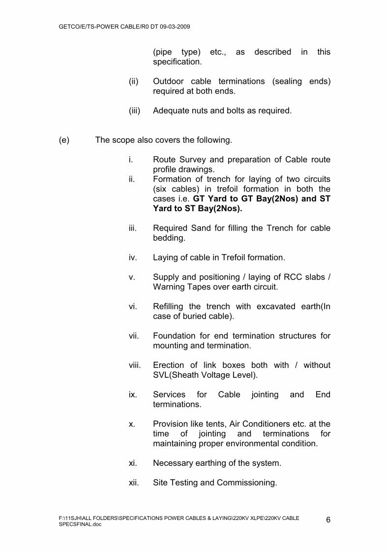
(pipe type) etc., as described in this specification.
(ii) Outdoor cable terminations (sealing ends)
required at both ends.
(iii) Adequate nuts and bolts as required.
(e) The scope also covers the following.
i. Route Survey and preparation of Cable route profile drawings.
ii. Formation of trench for laying of two circuits (six cables) in trefoil formation in both the cases i.e. GT Yard to GT Bay(2Nos) and ST Yard to ST Bay(2Nos).
iii. Required Sand for filling the Trench for cable bedding.
iv. Laying of cable in Trefoil formation.
v. Supply and positioning / laying of RCC slabs /
Warning Tapes over earth circuit.
vi. Refilling the trench with excavated earth(In case of buried cable).
vii. Foundation for end termination structures for
mounting and termination.
viii. Erection of link boxes both with / without SVL(Sheath Voltage Level).
ix. Services for Cable jointing and End
terminations.
x. Provision like tents, Air Conditioners etc. at the time of jointing and terminations for maintaining proper environmental condition.
xi. Necessary earthing of the system.
xii. Site Testing and Commissioning.

GETCO/E/TS-POWER CABLE/R0 DT 09-03-2009
F:\11SJH\ALL FOLDERS\SPECIFICATIONS POWER CABLES & LAYING\220KV XLPE\220KV CABLE SPECSFINAL.doc
7
xiii. Supply of Cable route markers and fixing them on either side of cable route at every 200 meters interval.
(f) It is not intent to specify completely all the details required
for the above cable system. However, the cable system shall be designed to carry possible maximum power in each circuit minimum and induced voltage in the sheath shall not exceed 60 V, under full load conditions, duly taking into consideration length of cable route and adopting suitable cable sheath bonding system, minimizing the sheath and accessories shall conform in all respects to the high standard of engineering design and workmanship and shall be capable of performing in continuous commercial operation up to the suppliers guarantee. The cable system offered shall be complete with all the components necessary for its effective and trouble free operation and all components required shall be deemed to be within the scope of the bidder.
(g) T&P (Tools & Plant) required for laying, Jointing and
termination shall be arranged by the bidder. The job is on turnkey basis.
Note: The scope shall cover supply of all required equipments Accessories, spares and jointing kits and tools and plant, competent supervision and consumables. All other matching materials requires (whether specifically mentioned or not) for complete installation, testing and commissioning of the system. Any items / equipment which are having shelf life shall be brought to site at the time of erection only. GETCO is not responsible for any such material becoming un-usable due to delay in execution of the project.
2.0 STANDARDS
(a) The 220 kV XLPE UG Cable shall conform to the following Indian / International Standards, which shall mean latest
revisions, amendments / changes adopted and published, unless otherwise specified herein before. International and Internationally recognized standards to which these standards generally correspond are also listed below:
Sl No.
Indian Standards
Title International Standards

GETCO/E/TS-POWER CABLE/R0 DT 09-03-2009
F:\11SJH\ALL FOLDERS\SPECIFICATIONS POWER CABLES & LAYING\220KV XLPE\220KV CABLE SPECSFINAL.doc
8
1. IS:7098 Part-3
Specification for XLPE insulated PVC sheathed cables
BS-5468
2. IS:1255 Code of practice for laying of power cables
3. IS-5831 PVC Insulation & sheath of electric cables
4. IS-3043 Code of practice for earthing 5. IS-5216 Guide for safety procedure and
practices in Electrical works
6. IS-8130 Conductors of Insulated Cables IEC-60228. 7. Guide to the dimensional limits of
circular Conductors IEC-60228A
8. Tests on cable over sheath, Power cables, Insulators
IEC-60229, IEC-60840, IEC-60230,
9. Power Cables with extruded insulation and their accessories
IEC 502-2
10. Calculation of continuous current rating of cables
IEC-60287
11. Electrical tests on extruded cables and Accessories for rated voltages > 150 kV and up to 420 kV.
IEC-62067
12. Indian Electricity Rules -1956 13. Tests on cable over sheath which have
a special protective function and are applied by extrusion
IEC-229
14. Power cables resistance of conductors IEC-2411408
The above standards are for guidance and shall be suitably extended for service voltage of 220 kV wherever applicable.
The standards mentioned above are available from:
Reference Abbreviation Name and Address BS British Standards Birtish Standards Institution, 101,
Pentonvile Road, N-19-ND UK IEC/ CISPR
International Electro technical Commission
Bureau Central de la Commission, Electro Technique International, 1 Rue de verembe, Geneva SWITZERLAND
BIS Bureau of Indian Standards,
Manak Bhavan, 9, Bahadur Shah Zafar Marg, New Delhi - 110 001, INDIA.
NEMA National Electric Manufacture
115, East 44th Street, New York NY 10017 U.S.A.

GETCO/E/TS-POWER CABLE/R0 DT 09-03-2009
F:\11SJH\ALL FOLDERS\SPECIFICATIONS POWER CABLES & LAYING\220KV XLPE\220KV CABLE SPECSFINAL.doc
9
Associate
(b) CONFILICT OF STANDARDS: Equipment conforming to other internationally accepted standards, which ensure equal or higher quality than the standards mentioned above, would also be acceptable. In case the Bidders who wish to offer material conforming to the other standards, salient points of difference between the standards adopted and the specific standards shall be clearly brought out in relevant schedule. Four copies of such standards with authentic English Translations shall be furnished alongwith the offer. In case of conflict the order of precedence shall be (i) IEC (ii) IS (iii) Other standards. In case of any difference between provisions of these standards and provisions of this specification, the provisions contained in this specification shall prevail.
3.0 CLIMATIC CONDITIONS
i) Location Sikka Thermal Power Station near Jamnagar in the state of Gujarat, India.
ii) Max. ambient air temp.of air in shade (deg. C)
50
iii) Min ambient air temp. of air in shade (deg.C)
4
iv) Maximum daily average ambient air temperature (deg. C)
40
v) Maximum daily average ambient air temperature (deg. C)
30
vi) Maximum Relative humidity (%) 95 vii) Average number of the thunder
storm days per annum 15
vii)i Average annual rainfall (mm) 150 ix) Average rainy days 90 days / year x) Max. wind pressure (kg/sq.m.) 150 xi) Max. altitude above mean seal
level (meters) 1000
xii) Max. soil temp.at cable depth(deg. C)
30 to 40
xiii) Soil thermal resistivity 150 Deg. C- cm / Watt at depth of 1.5Mtr.
4.0 PRINCIPAL PARAMETERS:
GETCO/E/TS-POWER CABLE/R0 DT 09-03-2009
F:\11SJH\ALL FOLDERS\SPECIFICATIONS POWER CABLES & LAYING\220KV XLPE\220KV CABLE SPECSFINAL.doc
10
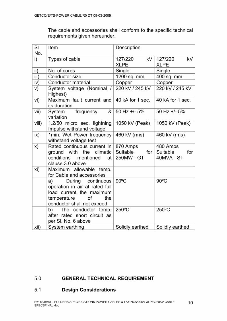
The cable and accessories shall conform to the specific technical requirements given hereunder.
Sl No.
Item Description
i) Types of cable 127/220 kV XLPE
127/220 kV XLPE
ii) No. of cores Single Single iii) Conductor size 1200 sq. mm 400 sq. mm iv) Conductor material Copper Copper v) System voltage (Nominal /
Highest) 220 kV / 245 kV 220 kV / 245 kV
vi) Maximum fault current and its duration
40 kA for 1 sec. 40 kA for 1 sec.
vii) System frequency & variation
50 Hz +/- 5% 50 Hz +/- 5%
viii) 1.2/50 micro sec. lightning Impulse withstand voltage
1050 kV (Peak) 1050 kV (Peak)
ix) 1min. Wet Power frequency withstand voltage test
460 kV (rms) 460 kV (rms)
x) Rated continuous current In ground with the climatic conditions mentioned at clause 3.0 above
870 Amps Suitable for 250MW - GT
480 Amps Suitable for 40MVA - ST
xi) Maximum allowable temp. for Cable and accessories
a) During continuous operation in air at rated full load current the maximum temperature of the conductor shall not exceed
90ºC 90ºC
b) The conductor temp. after rated short circuit as per Sl. No. 6 above
250ºC 250ºC
xii) System earthing Solidly earthed Solidly earthed
5.0 GENERAL TECHNICAL REQUIREMENT
5.1 Design Considerations
GETCO/E/TS-POWER CABLE/R0 DT 09-03-2009
F:\11SJH\ALL FOLDERS\SPECIFICATIONS POWER CABLES & LAYING\220KV XLPE\220KV CABLE SPECSFINAL.doc
11
5.1.1 The cable shall be suitable for buried installation with
uncontrolled back filling and laying in the area likely to be flooded by water. The cable shall withstand all mechanical and thermal stresses, which are likely to occur during its normal steady state and transient operation conditions.
5.1.2 The metallic screen shall be designed to withstand earth
fault current liable to occur in the system during conductor to ground fault as specified in clause 4.0(6).
5.1.3 The thermal receptivity of the soil is generally 150º C- cm /
watt. 5.1.4 The cable shall be designed to have a minimum useful life
of not less than fifty years. 5.1.5 Each cable length shall be provided with a pulling socket
pulling eye, which shall be fitted to pulling end. The pulling socket eye end shall be able to take the pulling tension of 2800 kgs., along with a reasonable factor of safety. The supplier shall confirm whether the cable can take this pulling load or not with supporting documents.
5.1.6 The outer sheath of the cable shall be given adequate
chemical treatment in order to protect itself from rodent and termite attack.
5.1.7 The conductor shall be clean, uniform in size and shape,
smooth and free from harmful effects. 5.1.8 The supplier shall supply the design calculations and
associated details along with the offer in order to establish the specified minimum continuous current rating and short time current rating of the cable.
5.2 Construction details 5.2.1. Cable construction and material for 220 KV XLPE
cables:
i) Conductor: Single core conductor shall consist of stranded, segmental/compacted circular annealed copper wires confirming to IEC-60228 / IS-8130. The wires shall be made of high conductivity copper and shall be stranded and compacted. The copper used for the conductor shall be highest purity. The

GETCO/E/TS-POWER CABLE/R0 DT 09-03-2009
F:\11SJH\ALL FOLDERS\SPECIFICATIONS POWER CABLES & LAYING\220KV XLPE\220KV CABLE SPECSFINAL.doc
12
nominal area of conductor shall be 1200/400 sq mm. The minimum number of wires in conductor and DC resistance of conductor shall be as per IEC 60228.
ii) Conductor screening: Conductor screening shall
consist of an extruded layer of thermosetting black semi conducting compound which shall be firmly bonded to the outer surface of the conductor and should cover the whole surface of the conductor and suitable for the operating temperature of the cable and compatible with the insulating material. The nominal thickness of the conductor screen should be as per latest relevant IEC.
iii) Insulation: Insulation shall be cross-linked
polyethylene (XLPE) and shall conform the latest IEC and of very high degree of purity and radiant cured (i.e., dry curing and dry cooling process). This XLPE insulation shall be applied by extrusion and vulcanized to form a compact homogenous body free from micro voids and contaminants. The nominal thickness of the insulation between conductor screen and insulation screen should be as per latest relevant IEC.
iv) Non-metallic part of insulation screening: The
insulation screen shall consist of an extruded layer of thermosetting of semi-conducting compound extruded directly over the insulation and shall be continuous and cover the whole surface area of insulation. It should be firmly bonded to the insulation and suitable for operating temp. of the cable and compatible with the insulating material. The conductor screening, insulation and insulation screening shall be extruded in one operation by single common head process to ensure homogeneity and elimination of voids. The nominal thickness of insulation screen should be as per latest relevant IEC.
v) Water blocking tape (Longitudinal Water Barrier):
This shall be Semi-conducting synthetic non-woven/woven tape with suitable swellable absorbent for longitudinal water sealing covering the whole surface area of the non-metallic part of insulation screening. This barrier shall restrict longitudinal

GETCO/E/TS-POWER CABLE/R0 DT 09-03-2009
F:\11SJH\ALL FOLDERS\SPECIFICATIONS POWER CABLES & LAYING\220KV XLPE\220KV CABLE SPECSFINAL.doc
13
water penetration under the metallic sheath. The nominal thickness of water blocking tape shall be as per latest relevant IEC.
vi) Metallic part of Insulation screening (Moisture
barrier): This shall consist of metallic sheath (Aluminium or Copper) and shall be impervious to moisture content, closely fitted and free from defects. The nominal thickness of metallic sheath shall be as per IEC.
vii) Bedding: Bedding shall consist of semi conducting
tape (s) of approx thickness 0.3 mm.
viii) Metallic screen: The Metallic screen shall consist of annealed plain copper wires applied over the Bedding. An open helix copper tape shall also be applied over the screen together can carry to specified fault current (40 kA for One second). The direction of lay of the screen wires shall be left hand. Joints in the screen wires shall be at least 300 mm from the nearest joint in any other screen wire in the complete cable. If the metallic part of insulation screen alone is capable to withstand fault current (40 kA), then there is no need of this metallic screen. The bidder shall furnish the calculations in support of their design, along with bid.
ix) Outer Jacket: The outer jacket will consist of
extruded, black, heavy duty PVC / PE / HDPE compound conforming to the requirement as per latest relevant IEC. The thickness of the outer jacket should be as per latest relevant IEC. The outer jacket shall be anti-rodent and anti-termite graphite coated extruded semi conducting layer. Extruded conducting layer would be preferred obtained by simultaneous extrusion with PVC / PE sheath, applied over outer jacket.
5.2.2. Cross bonding and earthing of metallic sheath.
In order to eliminate the sheath circulating current losses and consequent rise in potential, the metallic sheath at cable joints shall be cross bonded and earthed. The sheath of the three cables at the terminations shall be connected together at every joint and solidly earthed

GETCO/E/TS-POWER CABLE/R0 DT 09-03-2009
F:\11SJH\ALL FOLDERS\SPECIFICATIONS POWER CABLES & LAYING\220KV XLPE\220KV CABLE SPECSFINAL.doc
14
through disconnecting link boxes. It shall be possible to test the insulation of sheath by opening the link. The sheaths shall be insulated from ground at the switchyard sealing termination. The cable sheath covering and sheath insulators provided at the cable terminations shall be capable of with standing (with an ample safety margin) sheath voltages arising from maximum momentary fault current of 40 kA (rms). Cable covering protection units (CCPU) with surge diverters shall be provided between sheath and ground to protect the cable covering from surge voltages induced in the cable circuit. The sheath voltage under normal operating shall be around 50 to 60 volts to ground in any section. (Calculations shall be furnished to substantiate this).
5.2.3 The charging current of the cable shall be as low as
possible and shall be stated in the bid. The surge impedance of the cable shall be low so that the over voltage at the transformer terminals due to lightning surge remain well below its impulse level of 1050 kVp. Calculations for such over voltages shall be furnished alongwith the bid. The supplier in the offer shall also indicate suggested parameters for lightning arresters or use at the terminals.
5.2.4. Cable accessories
The sealing ends shall conform to the latest international standards and shall be of thoroughly proved design. The internal electric stress in the sealing end shall be controlled by the stress con arrangement preferably with semi-conductive bell mouth. The cable terminations shall be outdoor type. The outdoor type sealing ends shall b suitable for installation in polluted atmosphere referred to in clause 3.0 and shall be completely weather proof. Each outdoor-type sealing end shall be supplied complete with mounting plate insulators to insulate the sealing end from the supporting structures and to control the sheath current. If required, terminal connectors and bimetallic clamps shall also be supplied. Each sealing end shall be provided with consumption materials such as wiper and solvent for cleaning. The power cable leading to sealing end shall be provided with proper sunshield cover with flexible PVC pipe.
GETCO/E/TS-POWER CABLE/R0 DT 09-03-2009
F:\11SJH\ALL FOLDERS\SPECIFICATIONS POWER CABLES & LAYING\220KV XLPE\220KV CABLE SPECSFINAL.doc
15
a) Pre-Moulded Straight through joint: These joints shall be suitable for underground installation with uncontrollable backfill and for laying in areas likely to be flooded by water. These shall have adequate mechanical protection features. The surface shall be smooth and have no defects such as cracks, cuts and any other defects.
b) Outdoor Type Terminations
Outdoor type terminations shall be of well proven design and shall be manufactured in accordance with relevant standards and manufacturer's special instructions.
The termination shall complete with all fittings and terminating materials. In addition, the termination shall be supplied with consumption materials such as wiper and solvent for cleaning, emery cloth for insulation surface finishing as well as metal foil, protection tapes for cable annealing and straightening cable as necessary.
The conductor shall be connected by means of a compression ferrule or other approved arrangement . It shall be able to carry the maximum current under all possible circumstances without causing overheating and ensure the firm connection under mechanical possibility exposed in service.
The main insulation of the sealing end shall be of prefabricated type that shall be comparable or superior to the cable insulation in respect of electrical, thermal and mechanical characteristics under service and under short circuit conditions. The dielectric design of the termination shall be so optimized that the electric stress distribution along the stress relief cone and the able surface shall be well controlled without causing harmfully high electrical stress.
The housing of the outdoor type termination shall be porcelain insulator having uniform quality and shall have sufficient strength against mechanical, electrical and thermal stresses. The color of the porcelain insulator shall be brown. The porcelain insulator
GETCO/E/TS-POWER CABLE/R0 DT 09-03-2009
F:\11SJH\ALL FOLDERS\SPECIFICATIONS POWER CABLES & LAYING\220KV XLPE\220KV CABLE SPECSFINAL.doc
16
shall have sufficient creepage distance complying with the requirements of heavy pollution level specified in IEC 815.
The termination shall be isolated from the supporting structure by means of porcelain supporting insulators.
e) Pole Mounted Type Terminations
Pole Mounted type terminations shall be of well proven design and shall be manufactured in accordance with relevant standards and manufacturer's special instructions.
The termination shall be complete with all fittings and terminating materials. In addition, the termination shall be supplied with consumption materials such as wiper and solvent for cleaning, emery cloth for insulation surface finishing as well as metal foil, protection tapes for cable annealing and straightening cable as necessary.
The conductor shall be connected by means of a compression ferrule or other approved arrangement. It shall be able to carry the maximum current under all possible circumstances without causing overheating and ensure the firm connection under mechanical possibility exposed in service.
The main insulation of the sealing end shall be of prefabricated type that shall be comparable or superior to the cable insulation in respect of electrical, thermal and mechanical characteristics under service and under short circuit conditions. The dielectric design of the termination shall be so optimized that the electric stress distribution along the between the stress relief cone and the cable surface shall be well controlled without causing harmfully high electrical stress.
The housing of the Pole Mounted type termination shall be of silicon insulator having uniform quality and shall have sufficient strength against mechanical, electrical and thermal stresses. The color of the porcelain insulator shall be grey. The porcelain
GETCO/E/TS-POWER CABLE/R0 DT 09-03-2009
F:\11SJH\ALL FOLDERS\SPECIFICATIONS POWER CABLES & LAYING\220KV XLPE\220KV CABLE SPECSFINAL.doc
17
insulator shall have sufficient creepage distance complying with the requirements of heavy pollution level specified in IEC 815.
The termination shall be isolated from the supporting structure by means of silicon supporting insulators.
f) Link boxes : Link boxes shall be made of stainless
steel plate of sufficient mechanical strength and enclose links and CCPUs. The insulated type straight through joints shall be connected to cross link box by means of single core cable and through links and surge arrestors (CCPU) to be connected to earth. Provision for transposition of sheath and screen by cross bonding shall be made in cross-link boxes. The insulating plate to mount the terminals inside link box shall be of epoxy resin. The link plate and earthing terminal shall be of copper.
The link boxes in between the route shall be buried type and those at the termination and shall be structure-mounted type.
5.2.5 Identification
The external surface of the outer sheath shall be embossed with the following legend. "220 kV, 1200/400 sq., mm, XLPE, (Name of the supplier), (Year of Manufacture), property of GSECL ". The embossed letters and numerical shall be raised and shall consist of upright block characters along two lines, approximately and shall be equally spaced around the circumference of the cable. The size of the characters shall be approximately 13mm. The gap between the end of the one set of embossed characters and the beginning of the next shall not exceed 150mm.
Besides above, progressive sequential marking of length shall also be provided at every one meter, which shall be clear and legible and shall be contrast color.

GETCO/E/TS-POWER CABLE/R0 DT 09-03-2009
F:\11SJH\ALL FOLDERS\SPECIFICATIONS POWER CABLES & LAYING\220KV XLPE\220KV CABLE SPECSFINAL.doc
18
NOTE:
1) Any items / equipment which are having shelf life shall be brought to site at the time of erection only. GETCO is not responsible for any such material becoming un-usable due to delay in execution of the project.
2) "The Guaranteed Technical Particulars for
the equipment / material being supplied shall be provided with the bid as specified in the Technical Specification. The Bids without the Guaranteed Technical Particulars shall be treated as Non-Responsive."

GETCO/E/TS-POWER CABLE/R0 DT 09-03-2009
F:\11SJH\ALL FOLDERS\SPECIFICATIONS POWER CABLES & LAYING\220KV XLPE\220KV CABLE SPECSFINAL.doc
19
6.0 TESTS 6.1 Definitions of Tests 6.1.1 Routine Tests shall mean those tests, made by the
manufacturer on each manufactured component (cable or accessories ) to check that the component meets the specified requirements.
6.1.2 Acceptance Tests shall mean those tests, made by the
manufacturer on samples of cable or accessories taken from a complete cable / accessories offered for pre-dispatch inspection, at a specified frequency, so as to verify the finished product meets the specified requirements.
6.1.3 Type tests shall mean those tests conducted on a type of
cable system covered by the standards, before supplying it on a general commercial basis. Type tests are to be carried out to prove the process of manufacture and general conformity of the material to the specification. These tests shall be carried out from any one of the reputed International Test Laboratories mentioned below.
a) KEMA, Holland
b) EDF, France c) Hydro-Quebec, Canada d) CESI, Italy e) CPRI, Bangalore f) IPH Germany.
However, if the type test certificates produced are from any other internationally accredited test laboratory, the same will also be considered subject to verification of accreditation certification. The Type test reports shall not be older than 5 yrs and shall be valid till validity of offer.
6.1.4. Tests during manufacture shall mean those tests, which
are to be carried out during the process of manufacture and end inspection by the Bidder to ensure the desired quality of the end product to be supplied by him.
6.1.5 Tests after installation shall mean tests made to
demonstrate the integrity of the cable system as installed.

GETCO/E/TS-POWER CABLE/R0 DT 09-03-2009
F:\11SJH\ALL FOLDERS\SPECIFICATIONS POWER CABLES & LAYING\220KV XLPE\220KV CABLE SPECSFINAL.doc
20
6.1.6 For all type and acceptance tests, the acceptance values shall be the values guaranteed by the Supplier in the proforma for "Guaranteed Technical Particulars", furnished in this Specification or acceptance value specified in this specification, whichever is more stringent for that particular test.
6.1.7 Pre-qualification test shall mean those tests made before
supplying a cable system on a general commercial basis a type of cable system covered by this standard, in order demonstrate satisfactory long term performance of the complete cable system.
6.2 Test Reports to be enclosed.
The tests must have been conducted on the cables & Accessories as per IEC 62067.
6.2.1 Type Tests on Cable System
Following type tests shall be conducted on the complete cable as per IEC-62067.
a) Bending test followed by installation of accessories
and a partial discharge test at ambient temperature.
b) Tan Delta measurement (Dielectric power factor test) c) Heating cycle voltage test d) Partial discharge tests - at ambient temperature and
at high temperature. e) Lighting impulse voltage test followed by power
frequency voltage test. f) Tests of outer protection for buried joints. Note: Prior to conducting the above type tests check on
insulation thickness of the cable shall be carried out on a representative piece of cable length as per IEC-62067.
6.2.2. Type tests on accessories
All the type tests shall be carried out to prove the general qualities and design of given types of cable accessories. The type shall conform to the latest IEC 62067.
6.2.3 Pre-qualification test on cable system.
GETCO/E/TS-POWER CABLE/R0 DT 09-03-2009
F:\11SJH\ALL FOLDERS\SPECIFICATIONS POWER CABLES & LAYING\220KV XLPE\220KV CABLE SPECSFINAL.doc
21
The Pre-qualification test shall be carried out on given cable system. The Pre-qualification test shall conform to the latest IEC 62067. The bidders who are conducting PQ test shall be considered subject to the condition that the bidder shall submit an undertaking they will submit the test reports for the above before award of contract.
6.3 Routine tests, acceptance tests and special tests
The cable and accessories shall be subjects to all relevant routine, acceptance and special tests as described in IEC 62067 or any other relevant standards. The detailed list of such tests and copies of reports of such tests conducted on similar material shall be furnished with the offer. The Bidder is required to carry out all the acceptance tests successfully in the presence of Purchaser's representative before dispatch. All special and routine tests shall be performed at the factory in the presence of Purchaser's representative. All test reports shall be submitted and got approved by the purchaser before delivery of equipment.
6.4 Tests during installation
The cable shall be meggered before jointing. After jointing complete cable shall be tested before commissioning. The cable core shall be tested for
a) Continuity
b) Absence of cross phasing c) Insulation resistance to earth 6.5 Tests after installation
Following tests shall be carried out as per IEC - 62067 on the complete installation after completion of cable laying, jointing and providing all necessary accessories.
a) Insulation resistance test
b) DC/AC testing in accordance with IEC-62067 c) Site tests on non-metallic sheaths in accordance with
IEC-229. d) Test for detection and sealing of pinholes.
The supplier shall also indicate any additional special test at site recommended by them to ensure satisfactory operation.
GETCO/E/TS-POWER CABLE/R0 DT 09-03-2009
F:\11SJH\ALL FOLDERS\SPECIFICATIONS POWER CABLES & LAYING\220KV XLPE\220KV CABLE SPECSFINAL.doc
22
Note: Site Testing shall include tests before and during Installation, tests on the complete installation during and after completion of cable laying, cable jointing and completion of end terminations. Supplier shall carry complete testing and commissioning equipment.
6.6 Additional tests
The purchaser reserves the right for carrying out any other tests of reasonable nature at the works of the supplier / Laboratory or at any other recognized laboratory / research institute in addition to the above mentioned type, acceptance and routine tests at the cost of the purchaser to ensure that the material complies with the intent of this specification.
6.7 Commissioning tests
All the Commissioning tests shall be carried out before commissioning of the complete cable system. The type tests shall conform to the latest IEC 62067.
GETCO/E/TS-POWER CABLE/R0 DT 09-03-2009
F:\11SJH\ALL FOLDERS\SPECIFICATIONS POWER CABLES & LAYING\220KV XLPE\220KV CABLE SPECSFINAL.doc
23
7.1 INSPECTION 7.2 The purchaser may carry out inspection at any stage of
manufacture. The successful bidder shall grant free access to the purchaser's representative at a reasonable time when the work is in progress. Inspection and acceptance of any equipment under this specification by the purchaser shall not relieve the bidder of his obligation of furnishing equipment in accordance with the specification and shall not prevent subsequent rejection if the equipment is found to be defective. The supplier shall keep the purchaser informed in advance about the manufacturing program so that arrangement can be made for inspection. The purchaser reserves the right to insist for witnessing the acceptance / routine testing of the bought out items.
7.3 No material shall be dispatched from its point of
manufacture unless the material has been satisfactorily inspected and tested.
7.4 The supplier shall give 15 days (within India) / 45 days
(Other than India) advance intimation to enable the purchaser to depute his representative for witnessing types, acceptance and routine tests.

GETCO/E/TS-POWER CABLE/R0 DT 09-03-2009
F:\11SJH\ALL FOLDERS\SPECIFICATIONS POWER CABLES & LAYING\220KV XLPE\220KV CABLE SPECSFINAL.doc
24
8.0 QUALITY ASSURANCE PLAN 8.1 The bidder shall invariably furnish the following information
along with this offer failing which the offer shall be liable for rejection. Information shall be separately given for individual type of equipment offered.
i. The Structure of organization
ii. The duties and responsibilities assigned to staff
ensuring quality of work.
iii. The system of purchasing, taking delivery and verification of materials.
iv. The system for ensuring quality of workmanship.
v. The quality assurance arrangements shall conform to
the relevant requirement of ISO-9001 or ISO 9002 as applicable.
vi. Statement giving list of important raw materials,
names of sub-suppliers for the raw materials, list of standards according to which the raw material are tested, list of tests normally carried out on raw material in the presence of supplier representative, copies of test certificates.
vii. Information and copies of test certificates as on (i)
above in respect of bought out tems.
viii. List of manufacturing facilities available.
ix. Level of automation achieved and list of areas where manual processing exists.
x. List of areas in manufacturing process, where stage
inspections are normally carried out for quality control and details of such tests and inspections.
xi. List of testing equipment available with the bidder for
final testing of equipment specified and test plant limitation, if any vis-à-vis the type. Special acceptance and routine tests specified in the relevant standards. These limitations hall be very clearly
GETCO/E/TS-POWER CABLE/R0 DT 09-03-2009
F:\11SJH\ALL FOLDERS\SPECIFICATIONS POWER CABLES & LAYING\220KV XLPE\220KV CABLE SPECSFINAL.doc
25
brought out in "Schedule of Deviations" from the specified test requirements.
8.2 The Contractor shall within 30 days of placement of order,
submit the following information to the purchaser.
i) List of the raw material as well as bought out accessories and the names of sub-suppliers selected from those furnished alongwith the offer.
ii) Type test certificates of the raw material and bought
out accessories if required by the purchaser.
iii) Quality Assurance Plan (QAP) with holds points for purchaser's inspection. QAP and purchasers hold points shall be discussed between the purchaser and contractor before the QAP is finalized.
iv) The contactor shall submit the routine test certificates
of bough out accessories and central excise passes for raw material at the time of routine testing if required by the purchaser and ensure that the quality assurance requirements of specification are followed by the sub-contractor.
8.3 The Quality Assurance Program shall give a description of
the Quality System and Quality Plans with the following details.
i) Quality System:
• The Structure of the Organization • The duties and responsibilities assigned to staff
ensuring quality of work. • The system of purchasing, taking delivery of
verification of materials. • The system of ensuring of quality workmanship. • The system of control of documentation. • The system of retention of records. • The arrangement of contractor internal auditing.
a) A list of Administrator and work procedures required
to achieve contractors quality requirements. These procedures shall be made readily available to the purchaser for inspection on request.

GETCO/E/TS-POWER CABLE/R0 DT 09-03-2009
F:\11SJH\ALL FOLDERS\SPECIFICATIONS POWER CABLES & LAYING\220KV XLPE\220KV CABLE SPECSFINAL.doc
26
ii) Quality Plans:
• An outline of the proposed work and program sequence.
• The structure of contractor's organizations for the contract.
• The duties and responsibilities ensuring quality of work.
• Hold and notification points. • Submission of engineering documents
required by this specification. • The Inspection of the materials and
components on request. • Reference to contractors work procedures
appropriate to each activity. • Inspection during fabrication / construction. • Final Inspection and test.
9.0 DOCUMENTATION 9.1 All drawings shall conform to International Organization for
Standardization (ISO) 'A' series of drawing sheet / Indian Standards Specification. All drawings shall be in ink and suitable for micro filming. All dimensions and data shall be in S.I. units. Technical descriptions, data sheets, catalogues and other material submitted with the specification.
9.2 List of drawings and documents
The supplier shall furnish four sets of relevant, descriptive and illustratively published literature pamphlets and the following / particulars for preliminary study along with the offer.
i) General information and overall dimensional
(sectional) drawing. ii) Principal technical data. iii) Description of insulation and sheathing. iv) Cable current Vs temperature characteristics v) Drawings indicating phase transposition of cable
during laying. vi) Cable drum particulars and shipping dimensions vii) Drawings of joints and cable terminations.

GETCO/E/TS-POWER CABLE/R0 DT 09-03-2009
F:\11SJH\ALL FOLDERS\SPECIFICATIONS POWER CABLES & LAYING\220KV XLPE\220KV CABLE SPECSFINAL.doc
27
viii) Reference lists of supply and installed cable and accessories including customer identification and year of installation.
ix) List of accessories included in the offer. x) All relevant test reports as per Clause 6.0 and test
facilities available with the supplier. xi) Any other relevant particulars. 9.3 The successful supplier shall, within 2 weeks of placement
of order, submit four sets of final version of all the above drawings for purchaser's approval. The purchase shall communicate comments / approval on the drawings to the supplier within reasonable period. The supplier shall, if necessary, modify the drawings and resubmit four copies of the modified drawings for purchaser's approval within two weeks from the date of comments. After receipt of purchaser's approval the supplier shall, within three weeks, submit Ten (10) prints and two good quality reproducible of the approved drawings for owner's use. Further. The supplier shall also furnish the following calculations for the information of purchaser.
i) Current carrying capacity under laid condition.
ii) Sheath induced voltage under normal operating and fault condition.
iii) Guaranteed losses, namely conductor, sheath and dielectric losses at rated current.
9.4 The successful supplier shall also furnish ten (10) copies of bound manuals and two soft copies (in CD) covering all relevant information and drawings pertaining to the cable and accessories including laying and commissioning.
9.5 The manufacturing of the cable and accessories shall be
strictly in accordance with the approved drawings and no deviation shall be permitted. All manufacturing work against this specification prior to the approval of drawing shall be at supplier's risk.
9.6 Approval of drawings / work by the owner shall not relieve
the supplier of any of his responsibilities and liabilities for ensuring correctness and correct interpretation of the drawings for meeting the requirements of the latest revision of the applicable standards, rules and codes of practices. The cable and its accessories shall conform in all respects to high standards of engineering, design, workmanship and latest revision of relevant standards at the time of supply
GETCO/E/TS-POWER CABLE/R0 DT 09-03-2009
F:\11SJH\ALL FOLDERS\SPECIFICATIONS POWER CABLES & LAYING\220KV XLPE\220KV CABLE SPECSFINAL.doc
28
and purchaser shall have the power to reject any work or material which, in purchaser's judgment, is not in full accordance herewith.
9.7 Test Reports
i) Four copies of Type test reports shall be furnished to the owner within one week of conducting the test. One copy will be returned duly certified by the purchaser to the supplier within two weeks thereafter and on receipt of the same, supplier shall commence with the commercial production of the concerned material.
ii) Four copies of special or acceptance test reports
shall be furnished to the purchaser. One copy will be returned duly certified by the purchaser and only thereafter the material shall be dispatched.
iii) All records of routine test reports shall be maintained
by the supplier at his works for periodic inspection by the purchaser.
iv) The supplier shall maintain all test reports of tests
conducted during manufacture. These shall be produced for verification as and when requested for by the purchaser.
9.8 The bidder shall also prepare permanent records of all "as
built" cable installations. The record shall include the following field data:
a) Actual route map of cable.
b) Location of the cable in relation to existing facilities, etc., and depth.
c) Detailed drawing and various types of crossings. d) Position and types of all joints. e) Accurate lengths from joint to joint and
manufacturer's cable drum number.
The actual route map shall be prepared in sheets to the scale 1:500.The plan should contain detailed measurements of the cable and joints and all permanent land marks and subsoil obstructions. Detailed measurement of depth shall also be shown in cross sectional views.

GETCO/E/TS-POWER CABLE/R0 DT 09-03-2009
F:\11SJH\ALL FOLDERS\SPECIFICATIONS POWER CABLES & LAYING\220KV XLPE\220KV CABLE SPECSFINAL.doc
29
9.9 The successful bidder shall also furnish ten (10) copies of
bound manuals covering all relevant information and drawings pertaining to the cable and accessories including laying and commissioning.
9.10 Approval of drawings / work to be obtained for road
crossing, culvert crossing , bridge crossing, etc. shall be in the scope of Bidder. GETCO Engineer in Charge of work shall not relieve the bidder of any of his responsibilities and liabilities for ensuring correctness and correct interpretation of the drawings for meeting the requirements of the latest revision of the applicable standards rules and codes of practices.
10.0 PACKING AND FORWARDING
10.1 Supplier shall indicate in the offer, the maximum standard length of power cable, which can be supplied on one drum. Purchaser desires minimum standard lengths shall be such that joint can be avoided. The drawing can be referred with GETCO by the Bidder in order to finalize the single length of each size of cable.
10.2 The cut ends of the cable shall be sealed by means of non-
hygroscopic sealing material so as to protect the cable from moisture and other atmospheric effects during transit and laying. The following information shall be marked on the drum.
a) Trade name / Trade mark
b) Name of the manufacturer c) Nominal cross-sectional area of the conductor d) Type of cable and voltage e) Length of cable on the drum f) Direction of rotation of drum (Arrow) g) Gross weight of the drum h) Consignee i) Order No. j) Tare weight of drum. 10.3 The drum shall be of such construction as to ensure
delivery of cable at site free from displacement and damage and shall be able to withstand all stresses during handling in transit and laying. The drum shall be suitable for wheel mounting.
GETCO/E/TS-POWER CABLE/R0 DT 09-03-2009
F:\11SJH\ALL FOLDERS\SPECIFICATIONS POWER CABLES & LAYING\220KV XLPE\220KV CABLE SPECSFINAL.doc
30
10.4 Drums or parts of drums made from ferrous metals shall be
treated with suitable rust preventive finish or coating to minimize rusting during transit or storage.
10.6 Bolts, screws, nails etc., if used in the construction of drums
shall be counter sunk so that the heads are below the surface of the flange.
10.7 Drum construction, cable placement on the drum and the
installation of protective wrappings etc., shall be carefully coordinated to prevent damage to the cable during normal handling, ocean shipment and land transportation of the cable to site. The supplier shall also indicate the method of storage of cable drums at site in case the cables are to be stored for longer periods.
10.8 The cable accessories shall be packed suitably so as to
withstand handling during transit. The supplier shall be responsible for any damage during transit due to improper and inadequate packing and handling. The easily damageable material shall be carefully packed and marked with appropriate caution symbols. The supplier without any extra cost shall supply any material found short inside the packing cases.
10.9 Each consignment of cable accessories shall also be
accompanied by a detailed packing list containing the following information:
a) Name of the consignee
b) Details of consignment c) Destination d) Total weight of consignment e) Handling and unpacking instructions f) Bill of material indicating contents of each package.
The supplier shall ensure that, the packing list and bill of material are approved by the purchaser, before dispatch.
GETCO/E/TS-POWER CABLE/R0 DT 09-03-2009
F:\11SJH\ALL FOLDERS\SPECIFICATIONS POWER CABLES & LAYING\220KV XLPE\220KV CABLE SPECSFINAL.doc
31
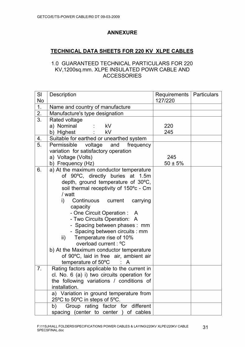
ANNEXURE
TECHNICAL DATA SHEETS FOR 220 KV XLPE CABLES
1.0 GUARANTEED TECHNICAL PARTICULARS FOR 220 KV,1200sq.mm. XLPE INSULATED POWR CABLE AND
ACCESSORIES
Sl No
Description Requirements127/220
Particulars
1. Name and country of manufacture 2. Manufacture's type designation 3. Rated voltage
a) Nominal : kV b) Highest : kV
220
245
4. Suitable for earthed or unearthed system 5. Permissible voltage and frequency
variation for satisfactory operation a) Voltage (Volts) b) Frequency (Hz)
245 50 ± 5%
6. a) At the maximum conductor temperature of 90ºC, directly buries at 1.5m depth, ground temperature of 30ºC, soil thermal receptivity of 150ºc - Cm / watt
i) Continuous current carrying capacity
- One Circuit Operation : A - Two Circuits Operation: A - Spacing between phases : mm
- Spacing between circuits : mm ii) Temperature rise of 10% overload current : ºC b) At the Maximum conductor temperature
of 90ºC, laid in free air, ambient air temperature of 50ºC : A
7. Rating factors applicable to the current in cl. No. 6 (a) i) two circuits operation for the following variations / conditions of installation.
a) Variation in ground temperature from 25ºC to 50ºC in steps of 5ºC.
b) Group rating factor for different spacing (center to center ) of cables

GETCO/E/TS-POWER CABLE/R0 DT 09-03-2009
F:\11SJH\ALL FOLDERS\SPECIFICATIONS POWER CABLES & LAYING\220KV XLPE\220KV CABLE SPECSFINAL.doc
32
installed in flat formation. 8. Short circuit capacity:
a) Short Circuit current kA (rms) b) Duration of short circuit (sec) c) Permissible conductor temperature for the short circuit duty with conductor temperature as 90ºC before inception of short circuit
Min. 40
Min. 1.0 Max. 250
9. Dielectric loss angle at normal frequency and rated voltage
10. Conductor :- a) Material b) Nominal cross sectional area (mm2)c) Number and nominal diameter of stands (No. / mm) d) Nominal diameter (mm) e) Maximum D.C. resistance of conductor for at 20ºC ( /Km) f) Maximum A.C. resistance of conductor for at 90ºC. ( /Km)
11. Impedances at 50 Hz 1.Positive & Negative Sequence = /Km 2. Zero sequence = /Km
12. Electro - static Capacitance at 50 Hz ( F/km)
13. Maximum charging current at the rated voltage (A/Km)
14. Conductor screening: a) Material b) Extruded / wrapped or both c) Nominal Thickness (mm)
15. Insulation: - a) Material of insulation (XLPE) b) Extrusion and curing system (VCV) c) Dry or steam curing (Dry) d) Extruder (Triple common) e) Thickness of insulation 1) Nominal Thickness (mm) 2) Minimum Thickness (mm) f) Variation of thickness as per IEC 60840 clause 10.6.2 g) Insulation resistance at 90ºC ( .m), 20º C ( .m) h) Maximum dielectric stress at the rated voltage (kV/mm) i) At the conductor screen (kV/mm)
23.0
GETCO/E/TS-POWER CABLE/R0 DT 09-03-2009
F:\11SJH\ALL FOLDERS\SPECIFICATIONS POWER CABLES & LAYING\220KV XLPE\220KV CABLE SPECSFINAL.doc
33
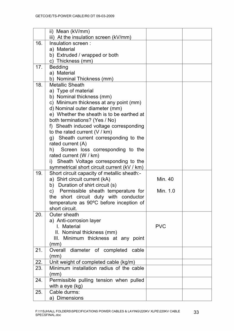
ii) Mean (kV/mm) iii) At the insulation screen (kV/mm)
16. Insulation screen : a) Material b) Extruded / wrapped or both c) Thickness (mm)
17. Bedding a) Material b) Nominal Thickness (mm)
18. Metallic Sheath a) Type of material b) Nominal thickness (mm) c) Minimum thickness at any point (mm) d) Nominal outer diameter (mm) e) Whether the sheath is to be earthed at both terminations? (Yes / No) f) Sheath induced voltage corresponding to the rated current (V / km) g) Sheath current corresponding to the rated current (A) h) Screen loss corresponding to the rated current (W / km) i) Sheath Voltage corresponding to the symmetrical short circuit current (kV / km)
19. Short circuit capacity of metallic sheath:- a) Shirt circuit current (kA) b) Duration of shirt circuit (s) c) Permissible sheath temperature for the short circuit duty with conductor temperature as 90ºC before inception of short circuit.
Min. 40
Min. 1.0
20. Outer sheath a) Anti-corrosion layer I. Material II. Nominal thickness (mm) III. Minimum thickness at any point (mm)
PVC
21. Overall diameter of completed cable (mm)
22. Unit weight of completed cable (kg/m) 23. Minimum installation radius of the cable
(mm)
24. Permissible pulling tension when pulled with a eye (kg)
25. Cable durms: a) Dimensions

GETCO/E/TS-POWER CABLE/R0 DT 09-03-2009
F:\11SJH\ALL FOLDERS\SPECIFICATIONS POWER CABLES & LAYING\220KV XLPE\220KV CABLE SPECSFINAL.doc
34
b) barrel diameter c) Gross weight (kg) d) Standard shipping length (m) c) Maximum shipping length (m)
26. Outdoor type terminations a) Name and country of manufacture b) Type of main insulation c) Material of the insulator d) Creepage distance (mm) e) Color of the insulator f) Weight of completed termination (kg) g) Whether cable termination is complete with all accessories (yes / no)
Brown Yes
27. Straight joint
a) Name and country of manufacture b) Type of main insulation c) Material of insulation flange d) Weight of competed joint i)Without protection box and compound
ii) With protection box and compound
28. a) Maximum dielectric loss of 3-phase cables laid in ground at the rated voltage, frequency and the maximum conductor temperature (kW/km) b) Total losses of 3 phase cables at the condition with the rated current (kw/km)
29. Attention to carrier signal operating over a frequency range of 50-200 kHz.
30. Phase to ground characteristic impedance at 50-200 kHz.
31. Maximum shelf life (a) Cable (Year) (b) Terminations (Year) (c) Straight joints (year)
32. 1 min wet power frequency withstand voltage (kV)
460
33. Lightning impulse withstand voltage (kVp) 1050 34. Maximum partial discharge magnitude at
the specified test voltage (pC)

GETCO/E/TS-POWER CABLE/R0 DT 09-03-2009
F:\11SJH\ALL FOLDERS\SPECIFICATIONS POWER CABLES & LAYING\220KV XLPE\220KV CABLE SPECSFINAL.doc
35
2.0 GUARANTEED TECHNICAL PARTICULARS FOR 220 kV,400sq.mm. XLPE
INSULATED POWER CABLE AND ACCESSORIES Sl No
Description Requirements127/220
Particulars
1. Name and country of manufacture 2. Manufacture's type designation 3. Rated voltage
a) Nominal : kV b) Highest : kV
220
245
4. Suitable for earthed or unearthed system 5. Permissible voltage and frequency
variation for satisfactory operation a) Voltage (Volts) b) Frequency (Hz)
245 50 ± 5%
6. a) At the maximum conductor temperature of 90ºC, directly buries at 1.5m depth, ground temperature of 30ºC, soil thermal receptivity of 150ºc - Cm / watt
i) Continuous current carrying capacity
- One Circuit Operation : A - Two Circuits Operation: A - Spacing between phases : mm
- Spacing between circuits : mm ii) Temperature rise of 10% overload current : ºC b) At the Maximum conductor temperature
of 90ºC, laid in free air, ambient air temperature of 50ºC : A
7. Rating factors applicable to the current in cl. No. 6 (a) i) two circuits operation for the following variations / conditions of installation.
a) Variation in ground temperature from 25ºC to 50ºC in steps of 5ºC.
b) Group rating factor for different spacing (center to center ) of cables installed in flat formation.
8. Short circuit capacity: a) Short Circuit current kA (rms)
Min. 40
GETCO/E/TS-POWER CABLE/R0 DT 09-03-2009
F:\11SJH\ALL FOLDERS\SPECIFICATIONS POWER CABLES & LAYING\220KV XLPE\220KV CABLE SPECSFINAL.doc
36
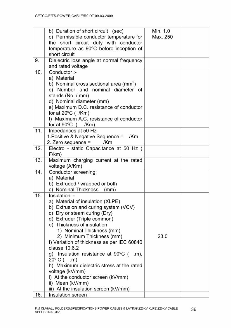
b) Duration of short circuit (sec) c) Permissible conductor temperature for the short circuit duty with conductor temperature as 90ºC before inception of short circuit
Min. 1.0 Max. 250
9. Dielectric loss angle at normal frequency and rated voltage
10. Conductor :- a) Material b) Nominal cross sectional area (mm2)c) Number and nominal diameter of stands (No. / mm) d) Nominal diameter (mm) e) Maximum D.C. resistance of conductor for at 20ºC ( /Km) f) Maximum A.C. resistance of conductor for at 90ºC. ( /Km)
11. Impedances at 50 Hz 1.Positive & Negative Sequence = /Km 2. Zero sequence = /Km
12. Electro - static Capacitance at 50 Hz ( F/km)
13. Maximum charging current at the rated voltage (A/Km)
14. Conductor screening: a) Material b) Extruded / wrapped or both c) Nominal Thickness (mm)
15. Insulation: - a) Material of insulation (XLPE) b) Extrusion and curing system (VCV) c) Dry or steam curing (Dry) d) Extruder (Triple common) e) Thickness of insulation 1) Nominal Thickness (mm) 2) Minimum Thickness (mm) f) Variation of thickness as per IEC 60840 clause 10.6.2 g) Insulation resistance at 90ºC ( .m), 20º C ( .m) h) Maximum dielectric stress at the rated voltage (kV/mm) i) At the conductor screen (kV/mm) ii) Mean (kV/mm) iii) At the insulation screen (kV/mm)
23.0
16. Insulation screen :

GETCO/E/TS-POWER CABLE/R0 DT 09-03-2009
F:\11SJH\ALL FOLDERS\SPECIFICATIONS POWER CABLES & LAYING\220KV XLPE\220KV CABLE SPECSFINAL.doc
37
a) Material b) Extruded / wrapped or both c) Thickness (mm)
17. Bedding a) Material b) Nominal Thickness (mm)
18. Metallic Sheath a) Type of material b) Nominal thickness (mm) c) Minimum thickness at any point (mm) d) Nominal outer diameter (mm) e) Whether the sheath is to be earthed at both terminations? (Yes / No) f) Sheath induced voltage corresponding to the rated current (V / km) g) Sheath current corresponding to the rated current (A) h) Screen loss corresponding to the rated current (W / km) i) Sheath Voltage corresponding to the symmetrical short circuit current (kV / km)
19. Short circuit capacity of metallic sheath:- a) Shirt circuit current (kA) b) Duration of shirt circuit (s) c) Permissible sheath temperature for the short circuit duty with conductor temperature as 90ºC before inception of short circuit.
Min. 40
Min. 1.0
20. Outer sheath a) Anti-corrosion layer I. Material II. Nominal thickness (mm) III. Minimum thickness at any point (mm)
PVC
21. Overall diameter of completed cable (mm)
22. Unit weight of completed cable (kg/m) 23. Minimum installation radius of the cable
(mm)
24. Permissible pulling tension when pulled with a eye (kg)
25. Cable durms: a) Dimensions b) barrel diameter c) Gross weight (kg) d) Standard shipping length (m)
GETCO/E/TS-POWER CABLE/R0 DT 09-03-2009
F:\11SJH\ALL FOLDERS\SPECIFICATIONS POWER CABLES & LAYING\220KV XLPE\220KV CABLE SPECSFINAL.doc
38
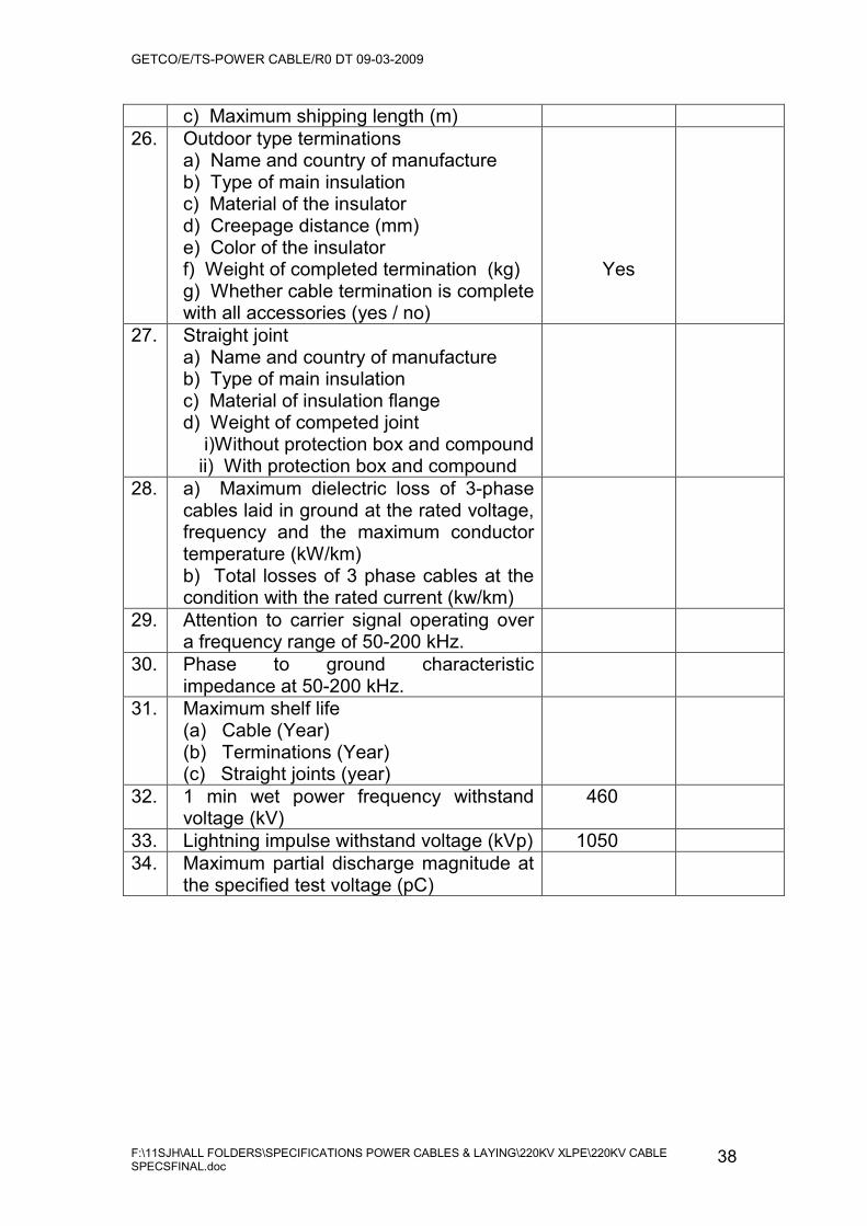
c) Maximum shipping length (m) 26. Outdoor type terminations
a) Name and country of manufacture b) Type of main insulation c) Material of the insulator d) Creepage distance (mm) e) Color of the insulator f) Weight of completed termination (kg) g) Whether cable termination is complete with all accessories (yes / no)
Yes
27. Straight joint a) Name and country of manufacture b) Type of main insulation c) Material of insulation flange d) Weight of competed joint i)Without protection box and compound
ii) With protection box and compound
28. a) Maximum dielectric loss of 3-phase cables laid in ground at the rated voltage, frequency and the maximum conductor temperature (kW/km) b) Total losses of 3 phase cables at the condition with the rated current (kw/km)
29. Attention to carrier signal operating over a frequency range of 50-200 kHz.
30. Phase to ground characteristic impedance at 50-200 kHz.
31. Maximum shelf life (a) Cable (Year) (b) Terminations (Year) (c) Straight joints (year)
32. 1 min wet power frequency withstand voltage (kV)
460
33. Lightning impulse withstand voltage (kVp) 1050 34. Maximum partial discharge magnitude at
the specified test voltage (pC)
GETCO/E/TS-POWER CABLE/R0 DT 09-03-2009
F:\11SJH\ALL FOLDERS\SPECIFICATIONS POWER CABLES & LAYING\220KV XLPE\220KV CABLE SPECSFINAL.doc
39
SEAL OF THE FIRM. SIGNATURE OF THE BIDDER.
NOTE: THE BIDDER MAY USE SEPARATE SHEET FOR FILLING UP ABOVE FORMAT FOR GIVING MORE DETAILS.

GETCO/E/TS-POWER CABLE/R0 DT 09-03-2009
F:\11SJH\ALL FOLDERS\SPECIFICATIONS POWER CABLES & LAYING\220KV XLPE\220KV CABLE SPECSFINAL.doc
40
GUARENTED TECHNICAL PARTICULARS FOR
EARTHING CABLE
SR NO DESCRIPTION
1. Manufacturer's name
2. a.
Voltage grade
3. Reference Standard
4. Conductor
1) Materials
2) Nominal cross sectional area (sq.mm)
3) Flexibility class
4) Form of conductor
5) Max. DC resistance of conductor at 20˚C(ohm/km)
5. Insulation
1) Materials
2) Nominal thickness(mm)
6. Approximate overall diameter of cable (mm)
7. (a) Short circuit current carrying capacity for 1 second duration (KA)
Signature of the Bidder: __________
Name:

GETCO/E/TS-POWER CABLE/R0 DT 09-03-2009
F:\11SJH\ALL FOLDERS\SPECIFICATIONS POWER CABLES & LAYING\220KV XLPE\220KV CABLE SPECSFINAL.doc
41
_______________________
Designation: ___________________
Date: _____________
Authorised common rubber
Stamp / seal of the bidder: _________
NOTE: THE BIDDER MAY USE SEPARATE SHEET FOR FILLING UP
ABOVE FORMAT FOR GIVING MORE DETAILS.