QUALITY ASSURANCE PLAN CHECK FORMATS FOR 220KV & 132KV … · for 220kv & 132kv transmission lines...
89
TRANSMISSION CORPORATION OF ANDHRA PRADESH LIMITED QUALITY ASSURANCE PLAN & CHECK FORMATS FOR 220KV & 132KV TRANSMISSION LINES AND SUBSTATIONS CONSTRUCTION
Transcript of QUALITY ASSURANCE PLAN CHECK FORMATS FOR 220KV & 132KV … · for 220kv & 132kv transmission lines...
TRANSMISSION CORPORATION OF ANDHRA PRADESH LIMITED
QUALITY ASSURANCE PLAN
&
CHECK FORMATS
FOR 220KV & 132KV TRANSMISSION LINES AND
SUBSTATIONS CONSTRUCTION
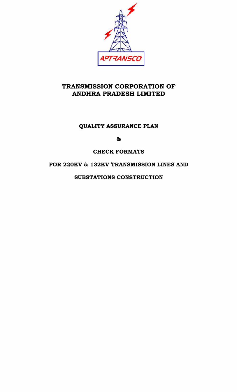
INDEX
______________________________________________________________________________ Sl.No. D E S C R I P T I O N PAGE NO: 1. PREAMBLE 1 2. CLSSIFICATION OF FOUNDATIONS 3 3. STANDARD FIELD QUALITY PLAN 7 4. GENERAL GUIDELINES FOR IMPLEMENTATION 22 5. REGISTERS (A) CEMENT REGISTER 40 (B) COARSE/FINE AGGREGATE REGISTER 42 (C) REINFORCEMENT STEEL REGISTER 50 (D) CONCRETE CUBE TESTS REGISTER 55

1
PREAMBLE
During the Quality Control Review Meeting on 03.08.2007 the
Chairperson and Managing Director/ APTransco has instructed to prepare the
quality assurance plan for erection of 132 KV and 220 KV lines & substations
for implementing in APTransco.
Accordingly, the Quality Assurance Plan is prepared for erection of
132 KV and 220 KV line & substations and approval accorded by technical
committee for implementing in APTransco.
2
The following issues were deliberated to ensure quality during execution of works:
1. Check Survey
i) Verification of line deviation angle and bisection for proper location of towers.
ii) Verification of meeting statutory clearances. iii) Check spans on either side of the tower location. iv) Mark distances and angles from angle point at 3 conspicuous
places to identify the angle point location in case of displacement of angle point peg.
v) At peg marks GPS marking should be done. This ensures correct position of peg even if it is removed, as the longitudes and latitudes are recorded.
2. Soil Investigation
i) Identify 75 locations for performing SPT. ii) SPT to be performed at all angle points, at locations where soil
strata changes, railway and national/state road crossings, power line crossings and special locations limiting to the 75 locations as provided in the contract.
iii) Instead of identify 75 locations, it is better to perform soil investigation for every KM of soil. Investigation is done by way of ERM method, time is saved and soil investigation can be done without disturbing standing crops.
3. Pit Marking
i) Mark position of all the four pits on the ground as per pit marking drawing for standard type of foundation and note levels of the center of each leg pit w.r.t center peg of the tower.
ii) Assess volume of bench cutting or use of hill side extension revetment if required and take approval of the Superintending Engineer /Chief Engineer.
4 . Foundation Classification
i) One of the foundation pit to be used as a trial pit and excavated as per normal soil dry type foundation.
ii) Observe following for classification - Type of cultivation surrounding tower and whether
encasement of stub required due to surface water. - Type of strata and depth of each layer. - Water table/level. - Maximum water table in the near by village well.
iii) Check and record soil classification and foundation classification
as per relevant clauses of the agreement and excavate pit as per approved drawing for the type of foundation classification. (Extract of Technical Specification is enclosed).
3 4.1 CLASSIFICATION OF FOUNDATIONS:
Classification of soil shall be made according to IS : 200 (Part I) 1974 for footing cast in open pits. The foundation designs for various types of Foundations as given below shall be adopted in the construction of all 132 kV & 220 kV Transmission Lines and shall be based on the following instruction. The Foundation Drawings as finalized by the Civil Engineering Wing for various soil conditions suitable for different Types of Towers being deployed in the construction shall be followed by all field officers strictly.
Sl.No. Soil at the Location of Tower Classification of
foundation to be adopted.
1. Where normal dry cohesive or non-cohesive soils are met. Dry 2(a). Where sub-soil water is met at 1.50 meters or more below the ground level
in normal soil (b) Where surface water could stand for long period with water penetration
not exceeding 1.0 m below ground level (e.g. Paddy fields, Sugarcane fields)
Wet
3(a). Where sub-soil water is encountered between 0.75 meter and 1.50 meters depth below ground level.
(b) Where top layer of Black Cotton soil extends up to 50% of the depth with normal soil thereafter
Partially Submerged / Partially Black
Cotton
Note – 1 Where soil is clayey type, not necessarily black in colour, which shrinks when dry, swells when wet.
4(a) Where sub-soil water Table is within 0.75 m depth from ground level. (b) Where top layer of Black Cotton soil exceeds 50% and extends up to full
depth or is followed by normal soil. (c) Where top layer is normal soil up to 50% of the depth but the lower layer
is a Black Cotton soil
Fully Submerged – Black Cotton
Note – 2 In case of items 4(a), (b) & (c) above, the concerned Superintending Engineer (Civil) shall personally inspect and certify on soil classification and shall not delegate this responsibility to any sub-ordinate officers.
5(a) Where decomposed or fissured rock, hard gravel, kanker, limestone, laterite or any other soil of similar nature is met.
(b) Where top layer of normal dry soil extends up to 85% of the depth followed by fissured rock without presence of water.
Fissured / soft rock
6(a) Where Hard rock is encountered at 1.5 m or less below ground level.
Hard Rock
(b) Where Hard rock is encountered form 1.5 m to 2.5 m below Ground Level though Top layer is of normal soil
(c) Where chiseling, drilling and blasting is required for excavation.
Note – 3 While classifying foundation of Wet, Partially Submerged / Partially Black Cotton, Fully Submerged / Black Cotton foundations mentioned above, the worst conditions may be considered and not necessarily the conditions prevailing at the time of inspection. For instance, there are areas where sub-soil water rises when canal water is let-out in the field raising sub-soil water to a considerable degree. Similarly the effect of monsoon or when the nearby reservoirs are full should be considered and not the conditions prevailing in open season or summer when work is carried out normally. In all such cases, the Chief Engineer (Civil) shall personally inspect and certify the requirement of higher classification on case to case basis.
4 Note – 4 For critical locations of cut-point / Angle Towers, the classification of Tower
Foundations may be at next higher type for ensuring safety of the transmission line as likely to be subjected to variable forces from time to time on account of change in season and climatic conditions. This shall be decided by the concerned Superintending Engineer (Civil) on case to case basis on personal inspection.
Note – 5 In case of highly collapsible & loose soils and river crossings, special design for foundations are to be made by Civil Engineering Wing for adoption on case to case basis.
Note –6 At locations subjected to water logging, particularly in paddy fields, ponds, marshy areas, etc., the chimney of all stubs to be raised to 600 mm over the normal chimney being adopted in other cases. This shall be done after complete erection of towers as a separate item for identified locations.
In addition to the above, depending on the site conditions more varieties of foundations may be introduced suitable for intermediate conditions under the above classifications to effect more economy. 5. Form Work Verify form work dimensions, rigidity, adequacy of tightness to prevent loss of cement water from concrete, ensure form surfaces in contact with concrete wetted and sprayed with fine sand/treated with black oil or waste oil/mould releasing agent every time before use. 6. Stub setting and Stub setting template
i) Recheck the depth of the pits w.r.t center peg level and pit dimensions as per approved foundation classification.
ii) Check under cutting as per approved drawing. iii) Position fully assembled and bolt tightened stub setting template
with supporting jacks placed on firm ground and level the template.
iv) Check placing a green concrete block of thickness equal to the clearance between the stub end and concrete to mitigate settling of template.
v) Check height of template above the center peg level.
7. Reinforcement
i) Check reinforcement dimensions as per bar bending schedule. Tie reinforcement at alternative crossing points with suitable binding wire.
ii) Verify using chair and gitties to ensure proper spacing in two layers reinforcement and minimum cover of 50 mm on the bars respectively.
iii) Before commencement of concreting ensure sufficient quantity of chairs and gitties are fabricated and made available at stores for use at locations.
5 8. Concrete Mixing
i) Ensure using coarse aggregate (metal) and fine aggregate (sand) as per IS-383.
ii) Check coarse aggregate for flakiness, soft stone and laminar shape. iii) Check cement for approved brand. iv) Ensure proper mixing of concrete as per the guide lines. v) After mixing and before placing the concrete in the foundation pit,
take samples for checking compressive strength and slump test of concrete.
vi) Engage ready mix where even possible to enable execute fast work. 9. Placing of Concrete
i) Check providing lean concrete (M 10) base 100 mm thick at bottom of the excavated pit before placing reinforcement.
ii) Use pointing/poking rod and vibrator for compaction of concrete ensuring vibrator head does not come in contact with steel, hardened concrete etc.,
10. Stripping of Form Work Ensure stripping formwork after about 24 hrs and check for any damage, honey combing and do necessary rectification. 11. Back Filling
i) Ensure back filling on foundation in layers and ensure proper consolidation.
ii) Ensure all top soils to be placed at the surface in case of towers located on cultivated land.
iii) Excess earth available over and above ground level (after consolidation) should be transported away from the site.
12. Curing Ensure proper curing by keeping adequate quantity of water and storing arrangement available at site.
13. Earthing of Tower
i) Ensure tower footing resistance not to exceed 10 Ohms. ii) Use pipe earthing or counter poise earthing as per approved
drawings to ensure minimum tower footing resistance. 14. Formats & QAP is revised with reference to the discussions and the revised formats & QAP are enclosed herewith. The Superintending Engineers should get the formats printed and bounded as registers and to ensure, they are distributed to Section Officer level. 15. All the foundation drawings, and other instructions shall be distributed upto Section Officer level.

6 16. PENALTIES IMPOSED FOR DEFICIENCEIES IN QUALITY OF WORKS:
During execution of works , if any deficiencies in quality of works is found in deviation to the specification / Agreement, a minimum penalty of Rs 5000 to Rs 30,000/- shall be levied for deficiencies as per each category as mentioned below.
Category I : Not using (i) prescribed shoring, shuttering and dewatering
equipment, (ii) measurement boxes, (iii) Form boxes for different types of foundations and steel measuring boxes, (iv) not providing adequate number of chairs to the steel reinforcements, (v) not carrying out back filling and compaction of the foundation pits in layers and leveling the tower footings properly, (vi) not ensuring that the excavated earth is dumped at least 2 meters away from the pit etc., and (vii) not providing copings to the tower legs / stubs,(viii) not providing water tanker, Earth rammers/Earth vibrators.
Category II : Use of reinforcement steel without ISI marking, not using
vibrators for effective consolidation of the concrete during foundation works, not using proper templates for firmly keeping the stubs in position when templates are supplied by the contractor & improper fixing of stubs, non ensuring of tower verticality, use of rusted stubs and tower parts if supply is by the contractor, non painting of butt joints and rusted stubs with zinc rich paint immediately after erection of the towers & stringing, non fixing of earth flat to the stub, non deployment of technical personnel for supervision of works by the contractor. Also not fixing of vibration dampers firmly, repair sleeves wherever necessary, not properly fixing of arcing horns both tower side and line side and bird guards etc., as per specification.
Category III : Use of improper grade / quality of raw material like H.B.G. metal, water and sand for concreting, using clogged and / or lump / clotted cement for concreting, not ensuring proper curing for foundation concrete, not ensuring that all the members of the tower are placed in position and firmly fixed with bolts and nuts immediately after erection of tower, not ensuring that Half round seam welding of the nuts before stringing of the line.
For the deficiencies in the quality of works noticed by the Engineer , penalties shall be levied as given below:
Type of category
First instance(Rs)
Second instance (Rs)
Third instance (Rs)
Category I 5,000 /- 10,000/- 15,000 /-
Category II 7,500 /- 15,000/- 22,500 /-
Category III 10,000 /- 20,000/- 30,000 /-
In the event of fourth instance of noticing the deficiency of quality of works
in any of the above categories, the bidder shall be debarred from participating in future tenders for a period of one year.
The bidder shall give a specific undertaking accepting this clause.

7 TRANSMISSION CORPORATION OF ANDHRA PRADESH LIMITED
QUALITY CONTROL & INSPECTION DEPARTMENT
STANDARD FIELD QUALITY PLAN FOR 220/132 KV LINES & SUB-STATIONS
Section: SURVEY & SOIL INVESTIGATION Sl. No.
Component Operation & Description of Test
Sampling Plan with Basis
Reference Documents and Acceptance Norms
Testing Agency Remarks Checking Authority
1 DETAILED SURVEY & ALIGNMENT
(a) Field Survey/Walkover Survey
100% Technical specification Geogrphical Map, Route alignment, Route Plan & Measurement Schedules
Contractor Counter check and approval by APTRANSCO
AEE/EE/ SE
(b) Plotting of Route 100% Technical specification Field book, Geogrphical Map, Route alignment, Route Plan
Contractor Counter check and approval by APTRANSCO
AEE/EE/ SE
© Profiling 100% Technical specification Field book, Graph sheets, approved route alignment.
Contractor Counter check and approval by APTRANSCO
AEE/EE/ SE
(d) Tower Spotting 100% Technical specification Approved Tower spotting data & Sag Template, Field Book, approved route alignment
Contractor Counter check and approval by APTRANSCO
AEE/EE/ SE
(e) Tower Schedule (Proforma to be approved by (APTRANSCO)
100% Technical specification Approved Route alignment & route profile tower schedule, sag template, tower spotting data
Contractor Counter check and approval by APTRANSCO
SE/CE
2 Check Survey (a) Bisection of Angle/Accuracy
of Alignment 100% Technical specification
IS:5613, and other relevant standards. Approved Route Map & Route Profiles, Tower/line Schedule and Sag Template etc.
Contractor Counter check and approval by APTRANSCO for approval
AEE/EE/ SE
(b) Check for profile levels and electrical clearances
100% DO Contractor Counter check and approval by APTRANSCO for approval
AEE/EE/ SE
© Check for span marking and lengths
100% Technical specs IS:5613 and other relevant standards Apprd. Profile drgs. Tower schedule, tower spotting data.
Contractor Counter check and approval by APTRANSCO
EE/SE
(d) Check for tower type& position as per site condition
100% DO Contractor Counter check and approval by APTRANSCO
EE/SE
(e) Estimation of benching &Revtment volumes (as per site conditions)
100% Technical specification IS:5613 and other relevant standards Apprd. Tower leg location counters, approved profile
Contractor Counter check and approval by CE/400KV/L&SS/ APTRANSCO
Benching by EE/Field Revetment by SE
(f) Final Profile & tower schedule
100% Modified profile drawing and amended tower schedule
Contractor Counter check and approval by APTRANSCO
EE/SE/CE

8
Sl. No.
Component Operation & Description of Test
Sampling Plan with Basis
Reference Documents and Acceptance Norms
Testing Agency Remarks Checking Authority
3 Soil Investigation
A At Normal Locations
(i) Borelog/Trial Pit for obtaining details/types of soil encountered. Including gradation of samples at specified levels, ground water levels etc. (at center of tower)
At locations as indicated by
APTRANSCO
Technical specification IS:1498, 1892, 2720, 4464, 6935, SP-36 & and other relevant standards
Contractor/ APTRANSCO approved Agency
Counter check and approval by APTRANSCO The locations are to be identified and approved by APTRANSCO before carrying out soil investigation
AEE/EE/ SE
B Soil Resistivity One Location in a stretch of 2 to 3
Km or at locations approved by APTransco
IS:2131, IS 2720 and Technical Specifications
Contractor APTRANSCO approved agency
Counter check and approval by APTRANSCO
EE/SE
C Test on Soil and Rock Samples
Approval by APTRANSCO
C1 Test on soil samples
i Visual and Engineering classifications
DO Technical specification IS:5613, IS:1498 and other relevant specifications
AEE/EE/ SE
C2 Tests on Rock At locations as indicated by APTRANSCO
Technical specification IS:2131, IS:2720, IS:4078, 4474 and other relevant standards
Contractor APTRANSCO approved lab
Approval by APTRANSCO
AEE/EE/ SE
i Visual Classifications Technical specification IS:1498, 5613 and other relevant standards
4 Selection of Site for Material Storage
100% Technical specification, utility/industry storage document Wooden sleepers, wooden planks, tarpaulin, steel sheets, bricks, Barbed wire for fencing etc site shall be free from termites
Contractor Approval by APTRANSCO
EE/SE
5 Checking of Foundation Materials
A Cement Supply source to be approved by AP Transco
(i) Fineness For each source MTC shall be furnished for every lot of 200 MTs and part thereof
APTRANSCO Technical specification IS:269, 456, 1489, 4031, 8112, 12269 and other relevant standards
Manufacturer works/ APTransco approved test lab/ contractor
Review and approval of manufacturers test certificates (MTCS)/laboratory test results by APTRANSCO
AEE/EE/ SE
(ii) Compressive Strength DO DO DO DO DO
(iii) Initial & Final setting tim DO DO DO DO DO
iv) Soundness DD DO DO DO DO
(v) Chemical composition of Cement DO APTRANSCO Technical specification IS:269, 456, 1489, 4031, 8112, 12269 and other relevant standards
Manufacturer Review of manufacturers test certificates (MTCS)/laboratory test results by APTRANSCO
SE/CE

9
Sl. No.
Component Operation & Description of Test
Sampling Plan with Basis
Reference Documents and Acceptance Norms
Testing Agency Remarks Checking Authority
B Coarse Aggregates One sample per lot of 200Cum or part per each source for each size`
Technical specification IS :383, IS:2386 and IS:2430 & other relevant standards
APTRANSCO Approved Lab
Each source will be approved by APTRANSCO review and acceptance of test result by AP Transco
AEE/EE/ SE
(i) Determination of Particle size (sieve analysis)
One sample per lot of 200Cum or part per each source
Technical specification IS :383, IS:2386 and other relevant standards
Contractor/ APTransco approved lab
Each source to be approved by APTransco
AEE/EE/ SE
(ii) Flackiness Index DO Technical specification IS :383, IS:2386 and other relevant standards
Contractor/ APTransco approved lab
DO AEE/EE/ SE
(iii) Crushing Valve DO Technical specification IS :383, IS:2386 and other relevant standards
Contractor/ APTransco approved lab
DO AEE/EE/ SE
(iv) Specific gravity DO DO DO DO DO
v) Bulk Density DO DO DO DO DO
vi) Absorption Value DO DO DO DO DO
vii) Moisture Content DO DO DO DO DO
viii) Presence of deleterious materials
DO DO DO DO DO
C) Fine Aggregates One sample per lot of 200Cum or part per each source
Technical specification IS :236, 383, 456, 2386, 2430 and other relevant standards
Contractor/ APTransco approved lab
Each source will be approved by APTransco
AEE/EE/ SE
(i) Gradation/ Determination of Particle Size (Sieve analysis)
DO Technical specification IS :236, 383, 456, 2386, 2430, 4031 and other relevant standards
Contractor/ APTransco approved lab
Each source tol be by review and acceptance of test result by APTransco
AEE/EE/ SE
(ii) Specific gravity and density DO Technical specification IS :236, 383, 456, 2386, 2430, 4031 and other relevant standards
Contractor/ APTransco approved lab
DO AEE/EE/ SE
iii) Moisture Content DO DO DO DO DO
iv) Absorption Value DO DO DO DO DO
v) Bulk Density DO DO DO DO DO
vi) Presence of deleterious materials
DO DO DO DO DO
D) Water
(i) Suitability (Potable water is considered suitable for concreting)
One sample for source
Technical specification IS 456, IS:3025 and other relevant standards
Contractor Each source to be approved by APTransco
AEE/EE
(ii) Cleanliness (Visual Check) 100% DO DO DO AEE/EE
iii) P.H. Value One sample per source
DO Min-6 and Max-8
Contractor/ APTransco approved test lab
DO AEE/EE
E) Reinforcement Steel
(i) Identification & Size Random Technical specification and approved drawings & IS 432, 1139 & 1786 and other relevant standards
Contractor/ APTransco approved test lab
Review and approval of manufacturers test certificates (MTCS)/laboratory test results by APTRANSCO
AEE/EE/ SE

10
Sl. No.
Component Operation & Description of Test
Sampling Plan with Basis
Reference Documents and Acceptance Norms
Testing Agency Remarks Checking Authority
(ii) Strength (Tensile test, Yield stress/proof stress)
DO Contractor/ APTransco approved lab
DO AEE/EE/ SE
iii) Percentage elongation DO DO DO AEE/EE/ SE
iv) Bend Rebend Test Technical specification IS: 432, 1139, 1786 2502 and other relevant standards
Contractor/ APTransco approved lab
DO AEE/EE/ SE
v) Reverse bend test for HDS Wires
For steel as per IS 1786 under 10mm one sample per each 25 MT or part thereof 10mm-16mm one sample per each 35 MT or part thereof. Over 16 mm 1 sample per each 45 MT or part thereof. IS:432, and other approved
specification Contractor/ APTransco approved test lab
DO EE/SE
vi) Chemical analysis test One sample per source
IS:432, IS:1139, IS:1786 and specification
Contractor/ APTransco approved test lab
DO AE/EE/SE
F Earthing material
(i) Visual identification 100% Technical specification IS: 5613 and other relevant standards
Contractor Approval by APTRANSCO
CE/Const.
(ii) Bill of material & installation 100% Technical specification approved drawings & IS 5613
Contractor DO EE/SE
6 Tower Excavation
A) Before Excavation
(a) Checking of pegs condition as per line alignment
100% Every Location
Approved line alignment/profiles Tech. Specification. IS 4091, 5613, CBI & P Publication No.268 and other relevant standards
Contractor Counter check and approval by APTransco
AE/AEE
(b) Checking of pit marking as per drawing and RI
100% Every Location
Technical specification, IS:4091, 5613 & other relevant standards Approved, profile excavation and foundation drawings
Contractor Counter check and approval by APTransco
AE/AEE
© Trial Pit DO DO DO DO AE/AEE
(d) Classification of soil DO DO Joint inspection by APTRANSCO & contractor
Approval by APTRANSCO
AEE/ EE/ SE
(e) Pit marking DO Contractor Approval by APTRANSCO
AE/AEE
(f) Pit levels with reference to center peg levels
DO DO DO DO AE/AEE
(g) Depth of pits as per center peg level (estimate)
DO DO DO DO AE/AEE
(h) Benching (Where required) Where required Technical specification IS 5613, approved Foundation leg contour Profiles and other relevant standards
Benching implements/ Contractor
Approval by APTRANSCO
AE/AEE
B Excavation
(a) Dimensional conformity Each Location Technical specifications IS:3764, 408, 4091 &5613, SP:16 and other relevant standards Approved excavation Drgs./ Specification
Pit excavation tools/ contractor
Approval by APTRANSCO
AE/AEE

11
Sl. No.
Component Operation & Description of Test
Sampling Plan with Basis
Reference Documents and Acceptance Norms
Testing Agency Remarks Checking Authority
(b) Verticality & squareness of each pit
Each Location Technical specification IS: 3764 Joint inspection by APTRANSCO
Approval by APTRANSCO
AE/AEE
© Verification of classification of soil type and type of foundation
DO DO DO DO AE/AEE/ EE/SE
(d) Shoring and Strutting (Check durability strength & soundness of staging, fonts adequacy and specific livels)
As required Technical specification applicable state/ local body safety regulations
Steel sheets, wooden planks stuts etc/ contractor
Coutner check by AP Transco
AE/AEE/ EE
(e) Dewatering (Where required) As required Tech. Specification. IS:456 and other relevant standards
Diesel engine pumps. Etc. contractor
Coutner check by AP Transco
AE/AEE
C) Stub & Template
(a) Identification & Assembly 100% Every Location
Technical specification IS: 5613. Approved drawings of stub template and foundation drawing
Stub template, water level tapes, sand bags, Jacks etc/ Contractor
Counter check by APTransco
AE/AEE
(b) Stub Setting 100% every location
DO Green concrete pads, adjustable Jacks, Sand bags etc. contractor
DO AE/AEE
© Template levels width & diagonal 100% every location
DO DO DO AE/AEE
(d) Ground Clearance DO DO DO DO AE/AEE
(e) Stub clearance DO DO DO DO AE/AEE
(f) Tightening of bolts and muts for template, stubs & cleats
DO DO DO DO AE/AEE
D) SHUTTERING (Form work) Fixing of form boxes check for identification dimensions parallisation and squareness and equidistance from stubs
100% All collapsible location
Technical specification IS 456 and other relevant standards approved drawings
Joint inspection APTRANSCO & contractctor
Counter check and approval by APTRANSCO
AE/AEE
E) Concreeting 100% Technical specification IS 456 and other relevant standards & approved drawings
Joint inspection APTRANSCO & contractctor
Counter check and approval by APTRANSCO
AE/AEE
(a) Control, Concrete mixed design Technical specification IS 456 and other relevant standards & approved drawings
Joint inspection APTRANSCO & contractctor
Counter check and approval by APTRANSCO
AE/AEE/ EE
(i) Identification of material and water supply sources
100% Technical specification IS 383,456 IS:3025, 3550 and other relevant standards
Contractor Counter check and approval by APTRANSCO
AE/AEE/ EE
(ii) Determination of characteristics of aggregates, cement, water etc.
100% Technical specification IS 269,383,456, 3125, 3550 and other relevant standards
Contractor/ APTRANSCO approved test laboratory
Counter check of test results and approval by APTRANSCO
AE/AEE/ EE

12
Sl. No.
Component Operation & Description of Test
Sampling Plan with Basis
Reference Documents and Acceptance Norms
Testing Agency Remarks Checking Authority
(iii) Preperation of mix and taking of samples for strength (7days, 14 days & 28 days ) and slump report
100% Technical specification IS 456 and other relevant standards
Contractor/ APTRANSCO approved test laboratory
Counter check of test results and approval by APTRANSCO
AE/AEE/ EE
iv) Review of controlled concrete mix report
100% Technical specification IS 456 and other relevant standards
Contractor/ APTRANSCO approved test laboratory
Approval by APTRANSCO
AE/AEE/ EE
a) Mixing of concrete 100% Technical specification IS 456 and other relevant standards
Concrete Mixer, water drum, GI sheets, weigh mixing. Arrangement Approved concrete design mix report/ contractor
AE/AEE
(b) Padding/lean concrete base 100% DO and approved drawing
DO DO AE/AEE
© Reinforcement placing fixing as per bar bending schedule 2. Check for proper cover spacers and chairs. 3. Check whether lapping of bars are tied properly.
100% Technical specification IS:2502 and other relevant standards and approved drawing
DO DO AE/AEE/ EE
(d) Fixing of form boxes check for identification, dimensions parallisation and squareness and equidistance from stubs
100% Technical specification IS 456 and other relevant standards approved drawings
DO DO AE/AEE
(e) Placing of concrete and Ramming
DO Technical specification IS 456, IS:5613 and other relevant standards
Poking rods and concrete vibrator. Approved concrete design mix report/ Contractor
DO AE/AEE
(f) Fixing of chimeny colomn width length check square & parallelism & equidistance from stub
DO DO DO DO AE/AEE
(g) Placing concrete, poking & ramming
DO DO DO Gap between boxes & reinforcement rods should be maintained
AE/AEE
F) Box removal check for dimensional conformity and workmanship
100% Technical specification IS 456, and other relevant standards appoved Drgs.
APTRANSCO & Contractor
Reinforcement rods should not be exposed Boxes should not be opened after 24 hours. Approval by APTransco
AE/AEE

13
Sl. No.
Component Operation & Description of Test
Sampling Plan with Basis
Reference Documents and Acceptance Norms
Testing Agency Remarks Checking Authority
G) Backfilling 100% all Locations
Technical Specification/IS: 5613, and other relevant standards Boulder size 80 mm (Max)
Contractor Boulders of size more than 80mm should not be allowed for backfilling, sufficient water should be poured and rammed for every 200mm layer of earth, 100mm height earthen bund along with the side of excavation for filling water
AE/AEE/ EE
H) Coping and Curing 100% Technical Specification IS:5613, and other relevant standards and approved drawing
Contractor At locations in the paddy fields or in the low lying areas, the chimney is to be extended as per AP Transco Approved drawing. The corner reinforcement rods 200 mm below the final chimney level to be left un concerted and the extensions of chimney for this portion and coping shall be done after tower erection. Curing should be continued for minimum 15 days.
AE/AEE
I) Laying of Earthing (Pie or Counterpoise type). (Based on measurement of soil resistivity/ tower footing resistance)
100% all Locations
Technical specification IS 3403 Joint inspection by APTRANSCO & contractor
Earthing type will be decided by APTRANSCO
AE/AEE
6 A)
Concrete Cubes Testing 100% one sample for each location (One sample consists of min 4 test cubes for 28 days strength
Technical specification. IS 456, 516, 1199 and other relevant standards
contractor/. Approved laboratory by APTransco Standard Cube Moulds
Cubes mut be tested within a week of 20 days curing period and tests results should be approved before tower erection by APTRANSCO
AE/AEE/ EE
(i) Strength under compression DO DO DO Approval by APTRANSCO
EE/SE

14
(ii) Slump test DO DO DOtest Funnel and poking rod
DO AEE/EE
iii) Unit weight of concrete DO DO DO DO AEE/EE
B) Bricks
a) Ansorption Strength After 24 hours immersion in cold water
IS:3495 - 1966 Not more than 20% by weight
Contractor / approved testing LAB by APTRANSCO
AEE/EE/ SE
b) Compresive Strength ……..do…….. Not less than 40
Kg/Cm ……..do…….. AEE/EE/ SE
c) Efflorescence ……..do…….. Not more than "Moderate" ……..do…….. AEE/EE/ SE
C) Earth work and compaction control
a) Degree of compaction 1 test per 2000 Sq.m area
IS: 2720 (Par-28) Contractor / approved testing LAB by APTRANSCO
Review and acceptance of test results by APTRANSCO
SE/EE
D) Roads
Water Bound Macadam
a) Aggregate impact value 1 test per 250 Cum
IS: 2386 (Part-4) Contractor / approved testing LAB by APTRANSCO
Contractor / approved testing LAB by APTRANSCO
SE
b) Grading of aggregate and screening
2 tests per 250 Cum
IS: 2386 (Part-1) ……..do…….. ……..do…….. SE
c) Flakiness index and elongation index
1 test per 250 Cum
IS: 2386 (Part-1) ……..do…….. ……..do…….. SE
d) Atterberg limits of blinding material
1 test per 50 Cum IS: 2720 (Part-5) ……..do…….. ……..do…….. SE
e) Water absorption 1 test per source IS: 2386 (Part-30) ……..do…….. ……..do…….. SE
f) Thickness Regularly ……….. ……..do…….. ……..do…….. AE/AEE
7 Tower Erection
A) Material Checking
i) Checking of tower members for damage cleanliness, galvanizing & stacking
100& Technical Specifications IS:5613 & other relevant standards and approved drawings
Contractor Approval by APTRANSCO
AE/AEE/ EE
(ii) Checking of galvanized bolts & nuts step bolts d'shackle U bolts Spring Washer & accessories
DO DO DO DO DO
iii) Dimensional check Random DO DO DO DO
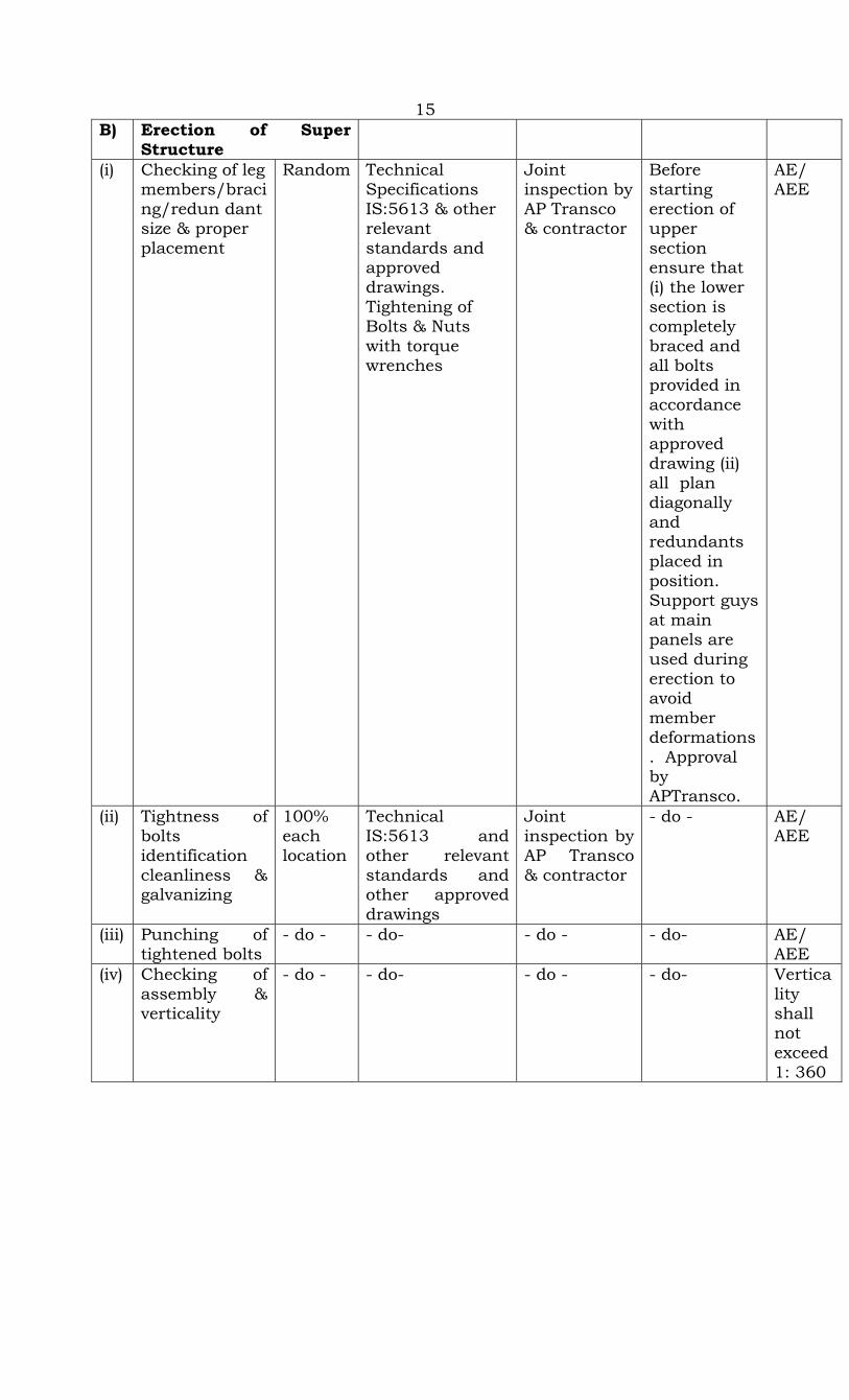
15 B) Erection of Super
Structure
(i) Checking of leg members/bracing/redun dant size & proper placement
Random Technical Specifications IS:5613 & other relevant standards and approved drawings. Tightening of Bolts & Nuts with torque wrenches
Joint inspection by AP Transco & contractor
Before starting erection of upper section ensure that (i) the lower section is completely braced and all bolts provided in accordance with approved drawing (ii) all plan diagonally and redundants placed in position. Support guys at main panels are used during erection to avoid member deformations. Approval by APTransco.
AE/ AEE
(ii) Tightness of bolts identification cleanliness & galvanizing
100% each location
Technical IS:5613 and other relevant standards and other approved drawings
Joint inspection by AP Transco & contractor
- do - AE/ AEE
(iii) Punching of tightened bolts
- do - - do- - do - - do- AE/ AEE
(iv) Checking of assembly & verticality
- do - - do- - do - - do- Verticality shall not exceed 1: 360

16 (v) Tack Welding 100%
each location
Technical IS:5613 and other relevant standards and other approved drawings
Joint inspection by AP Transco & contractor
Approval by APTRANSCO
Tack welding dia metrically opposite, length of each welding at least 10mm, 2 coats of Zinc rich paint on welded portion
vi) Tower footing resistance measurement before & after earthing
- do - - do - Measurement by 4 electrode methods by contractor
Approval by APTransco
AE/ AEE
vii) Fixing of danger plates, number plates & phase plates, circuit plates (i)Visual Check (ii) Dimensional check
- do - - do - By contractor
Approval by APTransco
AE/ AEE
8 Line Stringing A) Stringing (Sag
Tension) chart 100% Technical
Specification IS:5613, Sag Tension calculations and stringing chart approved by APTransco
Contractor Approval by APTransco
AE/ AEE/ EE
B) Checking of insulators identification cleanliness packing glazing
100% Technical Specification IS:731,5613,IEC 383 and other relevant
Joint inspection by APTransco & contractor
Approval not necessary
- do-

cracks & white spots, security clips
standards approved sag tension calculation and approved stringing chart
C) Measurement of IR Value
100% Technical Specification, IS:5613, and other relevant standards approved insulator megger dbe drawing,
APTransco/ contractor
Approval not necessary
IR shall be more than 50 M Ohms
D) Checking of insulators hardware fittings and conductor & ground wire accessories
100% Technical Specification, IS: 2121,2486,5613 and other relevant standards and approved drawings
APTransco/ contractor
Approval not necessary
(i) Identification, Cleanliness & packing
- do - - do- - do - - do-
(ii) Any mechanical damage
- do - - do- - do - - do-
(iii) Measurement of dimensions before and after making joint
- do - - do- - do - Hydraulic Compressor, measuring tape and scale vernier caliper/contractor & APTransco
Approval not necessary
(iv) Checking mechanical strength
Random Technical specification IS: 2121,2486,5613 and other relevant standards and approved drawings
A rigging set up to be fabricated in the field for testing mechanical strength. Contractor
Approval not necessary
Mech. Strength not to be less than 95% of UTS of conductor
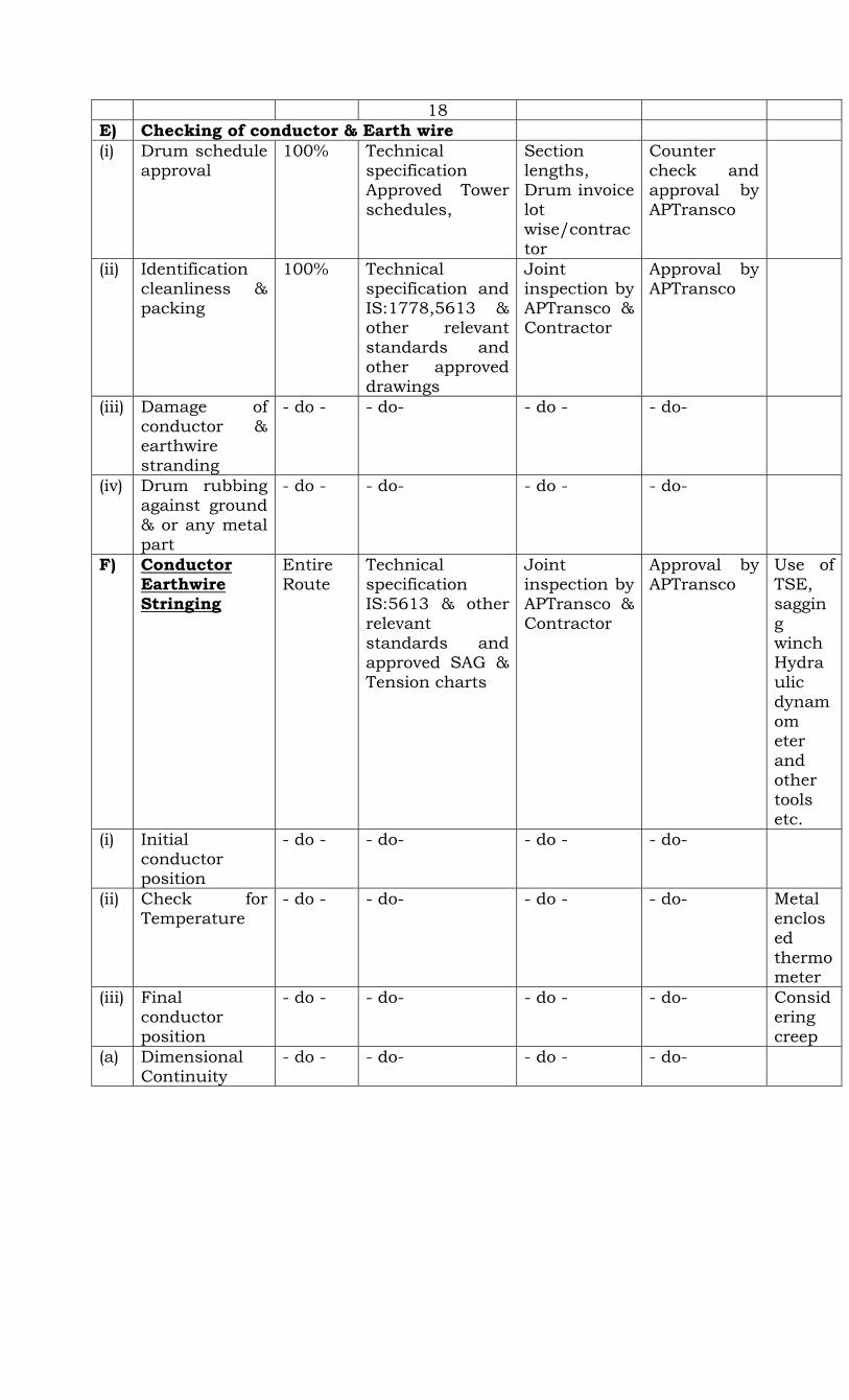
18 E) Checking of conductor & Earth wire (i) Drum schedule
approval 100% Technical
specification Approved Tower schedules,
Section lengths, Drum invoice lot wise/contractor
Counter check and approval by APTransco
(ii) Identification cleanliness & packing
100% Technical specification and IS:1778,5613 & other relevant standards and other approved drawings
Joint inspection by APTransco & Contractor
Approval by APTransco
(iii) Damage of conductor & earthwire stranding
- do - - do- - do - - do-
(iv) Drum rubbing against ground & or any metal part
- do - - do- - do - - do-
F) Conductor Earthwire Stringing
Entire Route
Technical specification IS:5613 & other relevant standards and approved SAG & Tension charts
Joint inspection by APTransco & Contractor
Approval by APTransco
Use of TSE, sagging winch Hydraulic dynamom eter and other tools etc.
(i) Initial conductor position
- do - - do- - do - - do-
(ii) Check for Temperature
- do - - do- - do - - do- Metal enclosed thermo meter
(iii) Final conductor position
- do - - do- - do - - do- Considering creep
(a) Dimensional Continuity
- do - - do- - do - - do-
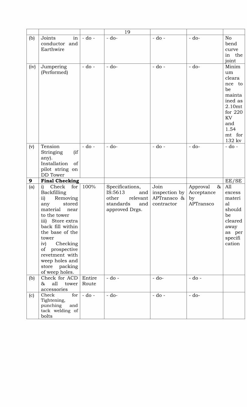
19 (b) Joints in
conductor and Earthwire
- do - - do- - do - - do- No bend curve in the joint
(iv) Jumpering (Performed)
- do - - do- - do - - do- Minimum clearance to be maintained as 2.10mt for 220 KV and 1.54 mt for 132 kv
(v) Tension Stringing (if any). Installation of pilot string on DD Tower
- do - - do- - do - - do- - do -
9 Final Checking EE/SE (a) i) Check for
Backfilling ii) Removing any stored material near to the tower iii) Store extra back fill within the base of the tower iv) Checking of prospective revetment with weep holes and store packing of weep holes.
100% Specifications, IS:5613 and other relevant standards and approved Drgs.
Join inspection by APTransco & contractor
Approval & Acceptance by APTransco
All excess material should be cleared away as per specification
(b) Check for ACD & all tower accessories
Entire Route
- do - - do- - do -
(c) Check for Tightening, punching and tack welding of bolts
- do - - do- - do - - do-
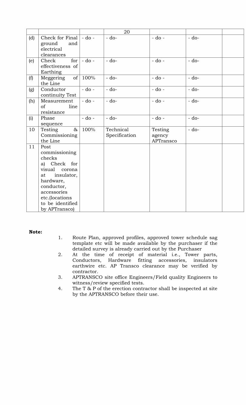
20 (d) Check for Final
ground and electrical clearances
- do - - do- - do - - do-
(e) Check for effectiveness of Earthing
- do - - do- - do - - do-
(f) Meggering of the Line
100% - do- - do - - do-
(g) Conductor continuity Test
- do - - do- - do - - do-
(h) Measurement of line resistance
- do - - do- - do - - do-
(i) Phase sequence
- do - - do- - do - - do-
10 Testing & Commissioning the Line
100% Technical Specification
Testing agency APTransco
- do-
11 Post commissioning checks a) Check for visual corona at insulator, hardware, conductor, accessories etc.(locations to be identified by APTransco)
Note:
1. Route Plan, approved profiles, approved tower schedule sag template etc will be made available by the purchaser if the detailed survey is already carried out by the Purchaser
2. At the time of receipt of material i.e., Tower parts, Conductors, Hardware fitting accessories, insulators earthwire etc. AP Transco clearance may be verified by contractor.
3. APTRANSCO site office Engineers/Field quality Engineers to witness/review specified tests.
4. The T & P of the erection contractor shall be inspected at site by the APTRANSCO before their use.
GENERAL GUIDE LINES FOR IMPLEMENTATION

22
Section: GENERAL GUIDELINES FOR IMPLEMENTATION 11 CEMENT 11.1 In case supply of cement is in the scope of the contractor, the same shall
be procured from sources approved by APTRANSCO site and got tested at site on sample basis for specified acceptance tests as specified in this FQP at a reputed Third Party Lab approved by APTRANSCO site.
11.2 The samples of cement for site testing shall be taken within three weeks
of the delivery and all the tests shall be commenced within one week of sampling.
12. REINFORCEMENT STEEL 12.1 In case supply of reinforcement steel is in the scope of the contractor, the
same shall be procured from the main producers i.e., SAIL, TISCO, HSCO or Rashtriya Ispat Nigam or the recollers approved by main procedures. The reinforcement steel shall be got tested at site on sample basis for specified acceptance tests as specified in this FQP at a reputed Third Party Lab approved by APTRANSCO site.
12.2 The result of the testing of cement and reinforcement steel referred to in
13.1 and 14.1 above shall be got approved from APTRANSCO site before cement and reinforcement steel are put to use. However, in exceptional cases due to exigencies of work. APTRASNCO site may authorize the contractor to use Cement and Reinforcement Steel even before the test results are received. However, in all such cases, if the test results subsequently received are found to be not complying with the specified acceptance criteria, the contractor shall have to dismantle and recase all such foundations cast with such non-conforming materials at his own cost. Confirmation to this effect shall be obtained from the contractor by the Project authorities beforehand in all such cases.
13. All the testing and measuring equipments used by the contractor for
testing are required to be calibrated. A copy of valid calibration report shall be retained by APTRANSCO as records.
14. Calibration certificates to be got verified from APTRANSCO for tools and
plants and testing equipment before their use.
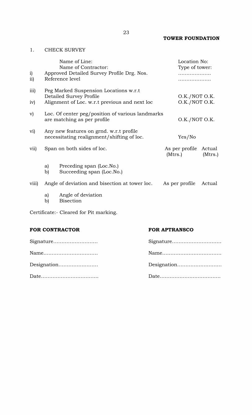
23 TOWER FOUNDATION 1. CHECK SURVEY Name of Line: Location No: Name of Contractor: Type of tower: i) Approved Detailed Survey Profile Drg. Nos. ……………….. ii) Reference level ……………….. iii) Peg Marked Suspension Locations w.r.t Detailed Survey Profile O.K./NOT O.K. iv) Alignment of Loc. w.r.t previous and next loc O.K./NOT O.K. v) Loc. Of center peg/position of various landmarks are matching as per profile O.K./NOT O.K. vi) Any new features on grnd. w.r.t profile necessitating realignment/shifting of loc. Yes/No vii) Span on both sides of loc. As per profile Actual (Mtrs.) (Mtrs.)
a) Preceding span (Loc.No.) b) Succeeding span (Loc.No.)
viii) Angle of deviation and bisection at tower loc. As per profile Actual
a) Angle of deviation b) Bisection
Certificate:- Cleared for Pit marking. FOR CONTRACTOR FOR APTRANSCO Signature……………………… Signature………………………… Name…………………………… Name……………………………… Designation…………………… Designation……………………… Date…………………………….. Date……………………………….
24
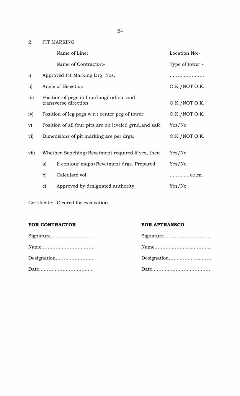
2. PIT MARKING Name of Line: Location No:- Name of Contractor:- Type of tower:- i) Approved Pit Marking Drg. Nos. …………………. ii) Angle of Bisection O.K./NOT O.K. iii) Position of pegs in line/longitudinal and transverse direction O.K./NOT O.K. iv) Position of leg pegs w.r.t center peg of tower O.K./NOT O.K. v) Position of all four pits are on leveled grnd.and safe Yes/No vi) Dimensions of pit marking are per drgs. O.K./NOT O.K. vii) Whether Benching/Revetment required if yes, then Yes/No a) If contour maps/Revetment drgs. Prepared Yes/No b) Calculate vol. ………….cu.m. c) Approved by designated authority Yes/No Certificate:- Cleared for excavation. FOR CONTRACTOR FOR APTRANSCO Signature……………………… Signature………………………… Name…………………………… Name……………………………… Designation…………………… Designation……………………… Date…………………………….. Date……………………………….

25 FOUNDATION CLASSIFICATION Name of Line: Location No:- Name of Contractor:- Type of tower:- i) Strata wise pit details STRATA DEPTH RECEIVING STRATA DEPTH --------------- ----------------- --------------- ----------------- --------------- ----------------- --------------- ----------------- PIT C/3 PIT B/2 STRATA DEPTH STRATA DEPTH --------------- ----------------- --------------- ----------------- --------------- ----------------- --------------- SENDING END ----------------- PIT D/4 PIT A/1 NOTE:CLASSIFICATION MAY ALSO BE GIVEN ON ONE PIT EXCAVATION BASIS FOR NORMAL DRY SOIL FOUNDATION DIMENSION a) Predominant soil ii) Sub soil water table details as on date.
PIT A/1 PIT B/2 PIT C/3 PIT D/4
iii) Water table in near by well as on date …………mtrs. iv) Maxm. Subsoil water table in monsoon season after through local enquiry ………….mtrs. v) Surface water table on grnd. In monsoon season and its duration. ………..mtrs.for……days vi) Type of cultivation Paddy fields/cultivate land/barren land Whether encasement of stubs reqd Due to surface water? Yes/No If yes, ht. of encasement above grad.level. …………mtrs.
26
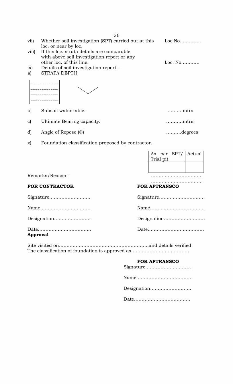
vii) Whether soil investigation (SPT) carried out at this Loc.No………….. loc. or near by loc. viii) If this loc. strata details are comparable with above soil investigation report or any other loc. of this line. Loc. No………… ix) Details of soil investigation report:- a) STRATA DEPTH --------------- --------------- --------------- --------------- b) Subsoil water table. ……….mtrs. c) Ultimate Bearing capacity. ………..mtrs. d) Angle of Repose () ……….degrees x) Foundation classification proposed by contractor.
As per SPT/ Trial pit
Actual
Remarks/Reason:- ……………………………. ……………………………. FOR CONTRACTOR FOR APTRANSCO Signature……………………… Signature………………………… Name…………………………… Name……………………………… Designation…………………… Designation……………………… Date…………………………….. Date………………………………. Approval Site visited on…………………………………………………..and details verified The classification of foundation is approved as………………………………… FOR APTRANSCO Signature………………………… Name……………………………… Designation……………………… Date……………………………….
27
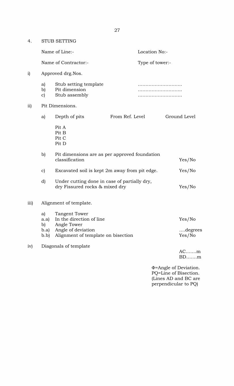
4. STUB SETTING Name of Line:- Location No:- Name of Contractor:- Type of tower:- i) Approved drg.Nos. a) Stub setting template ……………………….. b) Pit dimension ……………………….. c) Stub assembly ……………………….. ii) Pit Dimensions. a) Depth of pits From Ref. Level Ground Level Pit A Pit B Pit C Pit D b) Pit dimensions are as per approved foundation classification Yes/No c) Excavated soil is kept 2m away from pit edge. Yes/No d) Under cutting done in case of partially dry, dry Fissured rocks & mixed dry Yes/No iii) Alignment of template. a) Tangent Tower a.a) In the direction of line Yes/No b) Angle Tower b.a) Angle of deviation ….degrees b.b) Alignment of template on bisection Yes/No iv) Diagonals of template AC…….m BD…….m =Angle of Deviation. PQ=Line of Bisection. (Lines AD and BC are perpendicular to PQ)
28
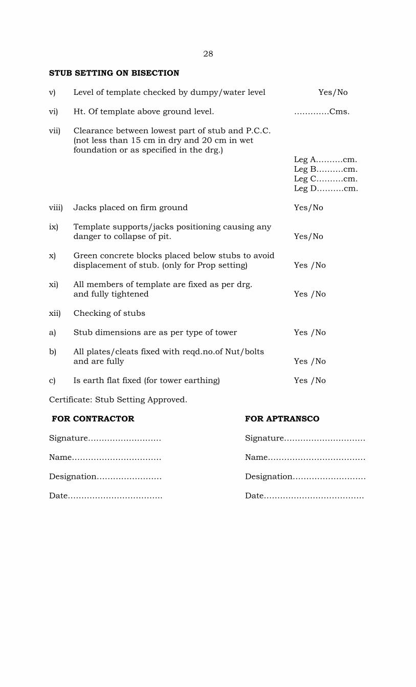
STUB SETTING ON BISECTION v) Level of template checked by dumpy/water level Yes/No vi) Ht. Of template above ground level. ………….Cms. vii) Clearance between lowest part of stub and P.C.C. (not less than 15 cm in dry and 20 cm in wet foundation or as specified in the drg.) Leg A……….cm. Leg B……….cm. Leg C……….cm. Leg D……….cm. viii) Jacks placed on firm ground Yes/No ix) Template supports/jacks positioning causing any danger to collapse of pit. Yes/No x) Green concrete blocks placed below stubs to avoid displacement of stub. (only for Prop setting) Yes /No xi) All members of template are fixed as per drg. and fully tightened Yes /No xii) Checking of stubs a) Stub dimensions are as per type of tower Yes /No b) All plates/cleats fixed with reqd.no.of Nut/bolts and are fully Yes /No c) Is earth flat fixed (for tower earthing) Yes /No Certificate: Stub Setting Approved. FOR CONTRACTOR FOR APTRANSCO Signature……………………… Signature………………………… Name…………………………… Name……………………………… Designation…………………… Designation……………………… Date…………………………….. Date……………………………….
29
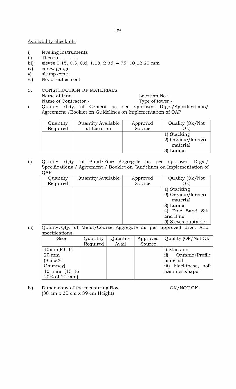
Availability check of : i) leveling instruments ii) Theodo ………… iii) sieves 0.15, 0.3, 0.6, 1.18, 2.36, 4.75, 10,12,20 mm iv) screw gauge v) slump cone vi) No. of cubes cost 5. CONSTRUCTION OF MATERIALS Name of Line:- Location No.:- Name of Contractor:- Type of tower:- i) Quality /Qty. of Cement as per approved Drgs./Specifications/ Agreement /Booklet on Guidelines on Implementation of QAP
Quantity Required
Quantity Available at Location
Approved Source
Quality (Ok/Not Ok)
1) Stacking 2) Organic/foreign material 3) Lumps
ii) Quality /Qty. of Sand/Fine Aggregate as per approved Drgs./ Specifications / Agreement / Booklet on Guidelines on Implementation of QAP
Quantity Required
Quantity Available Approved Source
Quality (Ok/Not Ok)
1) Stacking 2) Organic/foreign material 3) Lumps 4) Fine Sand Silt and if no 5) Sieves quotable.
iii) Quality/Qty. of Metal/Coarse Aggregate as per approved drgs. And specifications.
Size Quantity Required
Quantity Avail
Approved Source
Quality (Ok/Not Ok)
40mm(P.C.C) 20 mm (Slabs& Chimney) 10 mm (15 to 20% of 20 mm)
i) Stacking ii) Organic/Profile material iii) Flackiness, soft hammer shaper
iv) Dimensions of the measuring Box. OK/NOT OK (30 cm x 30 cm x 39 cm Height)
30
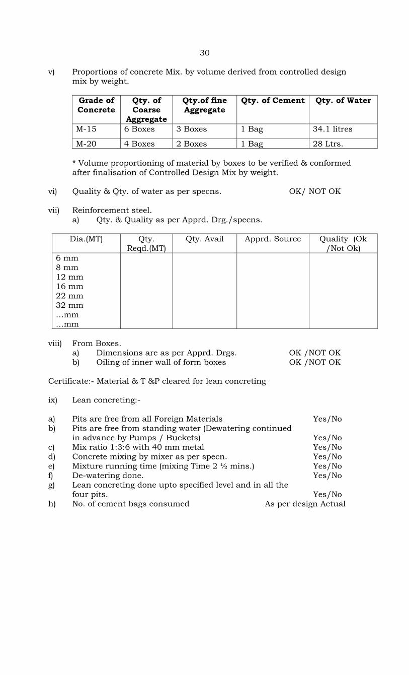
v) Proportions of concrete Mix. by volume derived from controlled design mix by weight.
Grade of Concrete
Qty. of Coarse
Aggregate
Qty.of fine Aggregate
Qty. of Cement Qty. of Water
M-15 6 Boxes 3 Boxes 1 Bag 34.1 litres
M-20 4 Boxes 2 Boxes 1 Bag 28 Ltrs. * Volume proportioning of material by boxes to be verified & conformed after finalisation of Controlled Design Mix by weight. vi) Quality & Qty. of water as per specns. OK/ NOT OK vii) Reinforcement steel. a) Qty. & Quality as per Apprd. Drg./specns.
Dia.(MT) Qty. Reqd.(MT)
Qty. Avail Apprd. Source Quality (Ok /Not Ok)
6 mm 8 mm 12 mm 16 mm 22 mm 32 mm …mm …mm
viii) From Boxes. a) Dimensions are as per Apprd. Drgs. OK /NOT OK b) Oiling of inner wall of form boxes OK /NOT OK Certificate:- Material & T &P cleared for lean concreting ix) Lean concreting:- a) Pits are free from all Foreign Materials Yes/No b) Pits are free from standing water (Dewatering continued in advance by Pumps / Buckets) Yes/No c) Mix ratio 1:3:6 with 40 mm metal Yes/No d) Concrete mixing by mixer as per specn. Yes/No e) Mixture running time (mixing Time 2 ½ mins.) Yes/No f) De-watering done. Yes/No g) Lean concreting done upto specified level and in all the four pits. Yes/No h) No. of cement bags consumed As per design Actual

31
x) In case of excess excavation filling is done by lean concrete & no loose soil is permitted for filling. Vol. of excess lean concrete. Certificate:- Pits are cleared for installation of reinforcement and form boxes. FOR CONTRACTOR FOR APTRANSCO Signature……………………… Signature………………………… Name…………………………… Name……………………………… Designation…………………… Designation……………………… Date…………………………….. Date……………………………….

32
6. INSTALLATION OF REINFORCEMENT STEEL & FORM BOXES Name of Line:- Location No.:- Name of Contractor:- Type of tower:- i) Apprd.Drg.Nos. ---------------------------- ---------------------------- ii) Reinforcement steel a) Quality/Qty. as per specification Yes/No b) Bending /Placing as per approved drg. Yes/No c) Required no. of chairs approved Yes/No (Min Dia-12 mm, Max. spacing-500mm) d) Binding done as per specifications. Yes/No e) Any undue stress or bending of steel bars Yes/No f) Steel is clean and free from loose rust or any other foreign matls Yes/No g) Position of bars w.r.t stub as per drg. OK /NOT OK iii) Form Boxes:- a) Dimensions as per approved drg. OK /NOT OK b) Placing w.r.t stub as per approved drg. OK /NOT OK iv) Clear cover of 50 mm (or as per specification available) Yes/No Certificate:- Cleared for foundation casting. FOR CONTRACTOR FOR APTRANSCO Signature……………………… Signature………………………… Name…………………………… Name……………………………… Designation…………………… Designation……………………… Date…………………………….. Date……………………………….
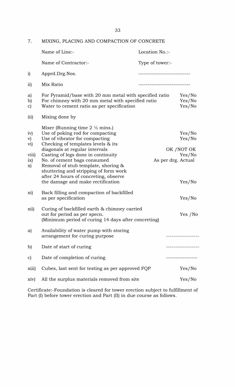
33 7. MIXING, PLACING AND COMPACTION OF CONCRETE Name of Line:- Location No.:- Name of Contractor:- Type of tower:- i) Apprd.Drg.Nos. ---------------------------- ii) Mix Ratio ---------------------------- a) For Pyramid/base with 20 mm metal with specified ratio Yes/No b) For chimney with 20 mm metal with specified ratio Yes/No c) Water to cement ratio as per specification Yes/No iii) Mixing done by Mixer (Running time 2 ½ mins.) iv) Use of poking rod for compacting Yes/No v) Use of vibrator for compacting Yes/No vi) Checking of templates levels & its diagonals at regular intervals OK /NOT OK viii) Casting of legs done in continuity Yes/No ix) No. of cement bags consumed As per drg. Actual x) Removal of stub template, shoring & shuttering and stripping of form work after 24 hours of concreting, observe the damage and make rectification Yes/No xi) Back filling and compaction of backfilled as per specification Yes/No xii) Curing of backfilled earth & chimney carried out for period as per specn. Yes /No (Minimum period of curing 14 days after concreting) a) Availability of water pump with storing arrangement for curing purpose ------------------ b) Date of start of curing ------------------ c) Date of completion of curing ----------------- xiii) Cubes, last sent for testing as per approved FQP Yes/No xiv) All the surplus materials removed from site Yes/No Certificate:-Foundation is cleared for tower erection subject to fulfillment of Part (I) before tower erection and Part (II) in due course as follows.

34 Part-I Setting period (28 days) is allowed as per specification Part-II (i) Revetment benching proposal status……………………………. (ii) Revetment benching likely execution date…………………….. FOR CONTRACTOR FOR APTRANSCO Signature……………………… Signature………………………… Name…………………………… Name……………………………… Designation…………………… Designation……………………… Date…………………………….. Date……………………………….

35 CONCRETE CUBE TEST REPORT Name of work : Agreement No. : Sample No. : Identification Mark : Portion of Work or Qty. represented sample: Date & Time of casting : Proportion of Mix : Duration of Curing at site and Site temperature before Transportation to test Lab and Temperature 7 days 28 days 1. Due date of test ……………….. …………… 2. Actual date of testing ……………….. …………… 3. Delay in testing ……………….. …………… 4. Actual Average compressive strength ……………….. ……………. 5. Is average comp. Strength equal to or Yes/No Yes/No more than specified comp.strength (Signature of Executing Agency) (Signature of APTransco Official) Date…………………………. Date………………………….
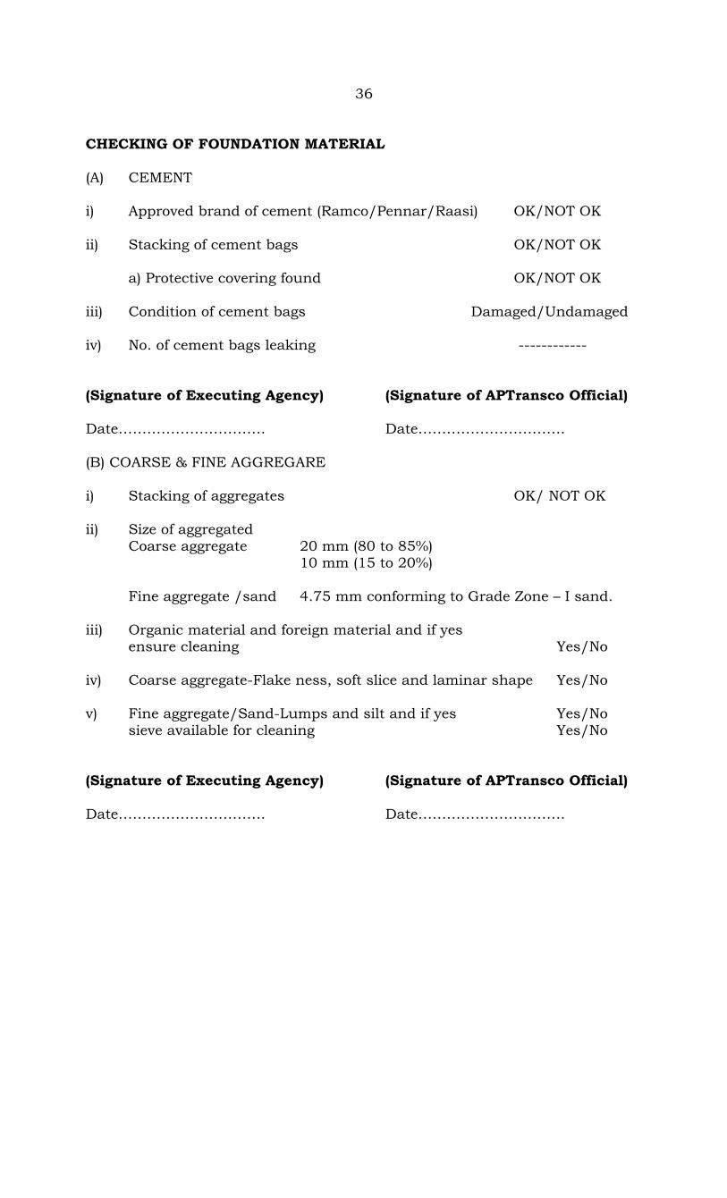
36 CHECKING OF FOUNDATION MATERIAL (A) CEMENT i) Approved brand of cement (Ramco/Pennar/Raasi) OK/NOT OK ii) Stacking of cement bags OK/NOT OK a) Protective covering found OK/NOT OK iii) Condition of cement bags Damaged/Undamaged iv) No. of cement bags leaking ------------ (Signature of Executing Agency) (Signature of APTransco Official) Date…………………………. Date…………………………. (B) COARSE & FINE AGGREGARE i) Stacking of aggregates OK/ NOT OK ii) Size of aggregated Coarse aggregate 20 mm (80 to 85%) 10 mm (15 to 20%) Fine aggregate /sand 4.75 mm conforming to Grade Zone – I sand. iii) Organic material and foreign material and if yes ensure cleaning Yes/No iv) Coarse aggregate-Flake ness, soft slice and laminar shape Yes/No v) Fine aggregate/Sand-Lumps and silt and if yes Yes/No sieve available for cleaning Yes/No (Signature of Executing Agency) (Signature of APTransco Official) Date…………………………. Date………………………….

37 (C) REINFORCEMENT STEEL i) Approved reinforcement bending schedule Drawing No…………………. ii) Dimensions and nos of the reinforcement bars and rigs Yes/No iii) Cleanliness of reinforcement bars from rust, mill deposit etc.,Yes/No iv) Binding wire availability Yes/No v) adequate fabricated chairs and gitties for supporting of reinforce bars availability Yes/No (Signature of Erection Agency) (Signature of APTransco Official) Date…………………………. Date………………………….

38
FORMAT FOR TEST REPORT OF WATER Name of line…………………………….. Source of water supply……………. Sample Indent Mark……………….. Name of Executing Agency…………….. Date……………………. Name & address of Test Lab ………………………………………………
………………………………………………
………………………………………………
………………………………………………
Test Report Ref. No…………………………………………..
Sl.No. Description Requirement/Tested
as per
Permissible limits (Max.)
1 Water Potable ---
Naturalization 100 ml H20
IS: 3025 5ml 0.02 Normal Na oH 2
* Using Phenolphthalein as indicator * Using Mixed indicator
25ml 0.02 Normal Na oH
3 PH Value IS:456 Not less than 6 Solids a) Organic IS:3025 200 mg/l b) In Organic IS:3025 3000 mg/l c) Sulphate (SO3) IS:3025 4000 mg/l d) Chlorides IS:3025 2000 mg/l (for non-
reinforced concrete)
4
e) Suspended Matter IS:3025 500 mg/l (for reinforced concrete)
5 Compressor strength (20 days) for three 150 mm concrete cubes made with proposed water Vis-a Vis similar cubes made with distilled water
IS: 516 90%

39
6 No. Description Requirement/ Tested as per
Permissible limits (Max.)
a) Initial setting time for test cube made with proposed water
IS: 4031 Not less than 30 months 7
b) Variation in initial setting time for test cube made with proposed water and distilled water
30 months
Note: Latest values may be seen by referring the latest IS code as amended as per Relevant standards (IS 3025, 456, 516, 4031) and APTRANSCO Technical Specification. (SIGNATURE OF LOCAL OFFICIAL) SIGNATURE OF ERECTION AGENCY DATE. DATE………………. SAMPLE IS APPROVED FOR CONCRETING (SIGNATURE OF APTRANSCO OFFICIAL) DATE…………………..
CEMENT REGISTER

41 CHECKING OF FOUNDATION MATERIAL (A) CEMENT Records of cement testing as
Per approved SFQP
(a) Details of samples
per 200 MT from each source are
maintained as per SFQP --------------------------
(b) All the tests as per approved SFQP are
carried out and details maintained --------------------------
(c ) Joint reports for collection of samples
in case of site testing are available --------------------------
(Signature of Erection Agency) (Signature of APTransco Official) Date…………………………. Date………………………….

COARSE/FINE AGGREGATE REGISTER

43
CEMENT RECEIPT & TEST FREQUENCY RECORD
Name of Line……………………………….. Location of …………………… Name of Erection Agency………………… Source of supply………………
Sl.N
o
Dat
e of
Rec
eipt
Bat
ch N
o./L
ot N
o.
Qty
. Rec
eive
d B
ags/
MT
Cu
m Q
ty. R
ecei
ved
Bag
s/M
T
Man
ufa
ctu
rer’
s Te
st
Cer
tific
ate
No.
& D
ate
APT
RA
NS
CO
App
rove
d La
b te
st R
epor
t N
o. &
D
ate
Test
Res
ult
s ar
e as
per
A
ppro
ved
SFQ
P
Sig
nat
ure
Note: (1) MTC shall be available for every 200 MT or part thereof (2) Lab Test Report shall be available for every 200 MT or part thereof

44
FORMAT FOR JOINT SAMPLING OF CEMENT
We have collected the sample of Cement as per following details joined: 1. Location of stores it: __________________________ 2. Source of supply : __________________________ 3. Type and Grade of cement: __________________________ (OPC/PPC, grade 33.43.53) 4. Batch No. /Lot No. of cement __________________________ 5. No. & Quantity of sample __________________________ 6. Name & Address of Lab where samples are being sent for testing __________________________ (vide letter No. & date) The samples have been sealed and one identification mark slip duly signed her
been placed inside the bag & another slip duly signed has been placed on the
bag.
(Signature of Erection Agency) Signature of APTransco Official Date………………………………… Date…………………………………

45
FORMAT FOR TEST REPORT OF CEMENT Name of line _________________________Source of Supply_________________ Name of Executing Agency ______________Sample Ident. Mark____________ Test Report Ref. No._____________________ Date:_________________________ Name & Address of Test Lab________________________________
Requirement as per Sl.No Particulars IS 269 33 Grade
OPC IS 8112 43 Grade
OPC IS 12269 53 Grade OPC
IS 1489-I & II, Fly Ash or Clay based
As per 3rd party Approved
Lab. Test Result
A. Chemical Properties -- 1. Cao-0.7 SO3 0.66 to 1.02 0.66 to 1.02 0.8 to 1.02
2. 2.8SiO2+1.2A12O3+0.65Fc2O3
3. 203% Fc203 0.66 MIN 0.66 MIN 0.66 MIN --
4. Insoluble Residue (%by mass)
4.0 MAX 2.0 MAX 2.0 MAX 13.6 to 2.8**
5. Magnesia(%by mass)
6.0 MAX 6.0 MAX 6.0 MAX 6.0 MAX
6. Sulphuric Anhydrite(% by mass)
3.0 MAX 3.0 MAX 3.0 MAX 3.0 MAX
7. Total loss of ignition(%)
5.0 MAX 5.0 MAX 5.0 MAX 5.0 MAX
8. Chloride(%) 0.05 MAX 0.05 MAX 0.05 MAX -- B. Physical Properties 1. Fineness
(SQM/Kg.) 225 MIN 225 MIN 225 MIN 300 MIN
2. Setting time (minutes) i) initial 30 MIN 30 MIN 30 MIN 30 MIN
ii) final 600 MAX 600 MAX 600 MAX 600 MAX
3. Soundness
a) Le-chat Expansion(MM)
i) Unacrated cement
10.0 MAX 10.0 MAX 10.0 MAX 10.0 MAX
ii) After 7 days Acration
5.0 MAX 5.0 MAX 5.0 MAX 5.0 MAX
b) Auto clave expansion (%) i) Uncrated
cement 0.8 MAX 0.8 MAX 0.8 MAX 0.8 MAX
ii) After 7 days Aeration
0.6 MAX 0.6 MAX 0.6 MAX 0.6 MAX
4. Compressive Strength (Mpa)
a) 72+/- 1 hour 16 MIN 22 MIN 27 MIN 16 MIN
b) 168 +/-2 hours
22 MIN 33 MIN 37 MIN 22 MIN
c) 672+ /-4 hours 33 MIN 43 MIN 53 MIN 33 MIN
** X+4.0(100-X)/100 Where X is the declared 1% of pozzolona in the given Portland pozzolona cement. X Ranger from 10 to 25%. Note: Latest values may be seen by referring the latest IS code as amended.

46 COARSE & FINE AGGREGATE Record of Coarse Aggregates testing as per approved SFQP a) Details of samples per 200 cum from Each source for each size (40mm, 20mm) And fine aggregate are maintained as per SFQP ---------------------- b) All tests as per approved SFQP are carried out and details maintenanced ---------------------- c) Joint Report for collection of Samples for testing at APTRANSCO Approved lab is available ---------------------- (Signature of Erection Agency) Signature of APTransco Official Date………………………………… Date…………………………………
47
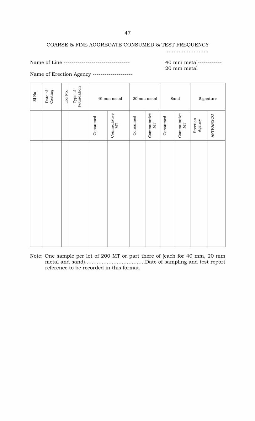
COARSE & FINE AGGREGATE CONSUMED & TEST FREQUENCY ……………………..
Name of Line --------------------------------- 40 mm metal------------ 20 mm metal Name of Erection Agency --------------------
Sl N
o
Dat
e of
C
asti
ng
Loc
No.
Type
of
Fou
nda
tion
40 mm metal
20 mm metal
Sand
Signature
Con
sum
ed
Com
mu
tati
ve
MT
Con
sum
ed
Com
mu
tati
ve
MT
Con
sum
ed
Com
mu
tati
ve
MT
Ere
ctio
n
Age
ncy
APT
RA
NS
CO
Note: One sample per lot of 200 MT or part there of (each for 40 mm, 20 mm metal and sand)………………………………Date of sampling and test report reference to be recorded in this format.

48
FORMAT FOR JOINT SAMPLING OF COARSE & FINE AGGREGATE
The sample of coarse line aggregate as per the following details have been collect ……………………….. (1) Location of sit (2) Source of supply Size of Aggregate Source 40 mm ……………… 20 mm ……………… Fine Aggregate ……………… (3) No. & Quantity of Samples taken (4) Name & address of Lab where samples are Being sent for testing (vide letter No. & date) The samples have been sealed and identification mark slip duly signed has
been placed inside the bag & another slip duly signed has been pasted on the
bags.
(Signature of Erection Agency) Signature of APTransco Official Date………………………………… Date…………………………………
49
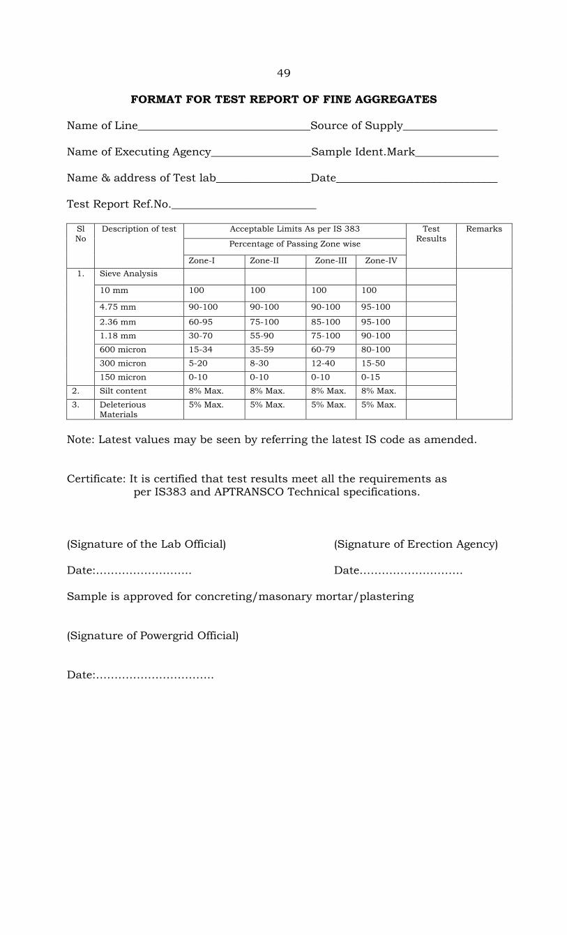
FORMAT FOR TEST REPORT OF FINE AGGREGATES
Name of Line_______________________________Source of Supply_________________ Name of Executing Agency__________________Sample Ident.Mark_______________ Name & address of Test lab_________________Date_____________________________ Test Report Ref.No.__________________________
Acceptable Limits As per IS 383
Percentage of Passing Zone wise
Sl No
Description of test
Zone-I Zone-II Zone-III Zone-IV
Test Results
Remarks
Sieve Analysis
10 mm 100 100 100 100
4.75 mm 90-100 90-100 90-100 95-100
2.36 mm 60-95 75-100 85-100 95-100
1.18 mm 30-70 55-90 75-100 90-100
600 micron 15-34 35-59 60-79 80-100
300 micron 5-20 8-30 12-40 15-50
1.
150 micron 0-10 0-10 0-10 0-15
2. Silt content 8% Max. 8% Max. 8% Max. 8% Max.
3. Deleterious Materials
5% Max. 5% Max. 5% Max. 5% Max.
Note: Latest values may be seen by referring the latest IS code as amended. Certificate: It is certified that test results meet all the requirements as per IS383 and APTRANSCO Technical specifications. (Signature of the Lab Official) (Signature of Erection Agency) Date:…………………….. Date………………………. Sample is approved for concreting/masonary mortar/plastering (Signature of Powergrid Official) Date:…………………………..
REINFORCEMENT STEEL REGISTER
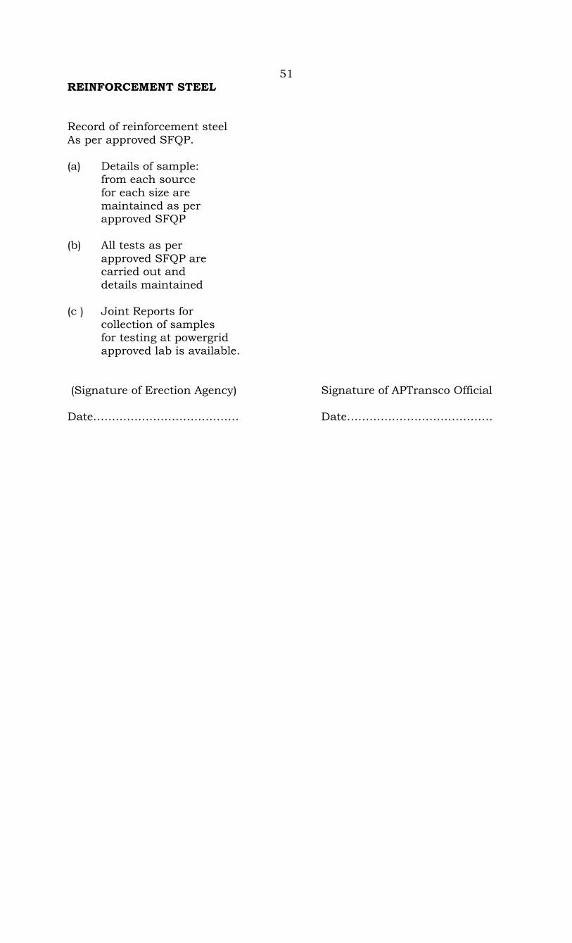
51 REINFORCEMENT STEEL Record of reinforcement steel As per approved SFQP. (a) Details of sample: from each source for each size are maintained as per approved SFQP (b) All tests as per approved SFQP are carried out and details maintained (c ) Joint Reports for collection of samples for testing at powergrid approved lab is available. (Signature of Erection Agency) Signature of APTransco Official Date………………………………… Date…………………………………
52
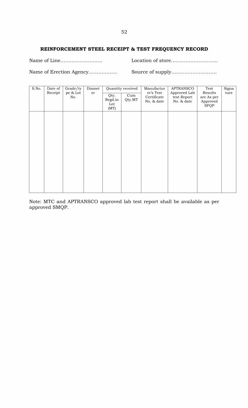
REINFORCEMENT STEEL RECEIPT & TEST FREQUENCY RECORD
Name of Line…………………….. Location of store……………………….. Name of Erection Agency……………… Source of supply……………………….
Quantity received S.No. Date of Receipt
Grade/type & Lot
No.
Diameter
Qty. Regd.in
Lot (MT)
Cum Qty.MT
Manufacturer’s Test
Certificate No. & date
APTRANSCO Approved Lab
test Report No. & date
Test Results
are As per Approved
SFQP
Signature
Note: MTC and APTRANSCO approved lab test report shall be available as per approved SMQP.
53
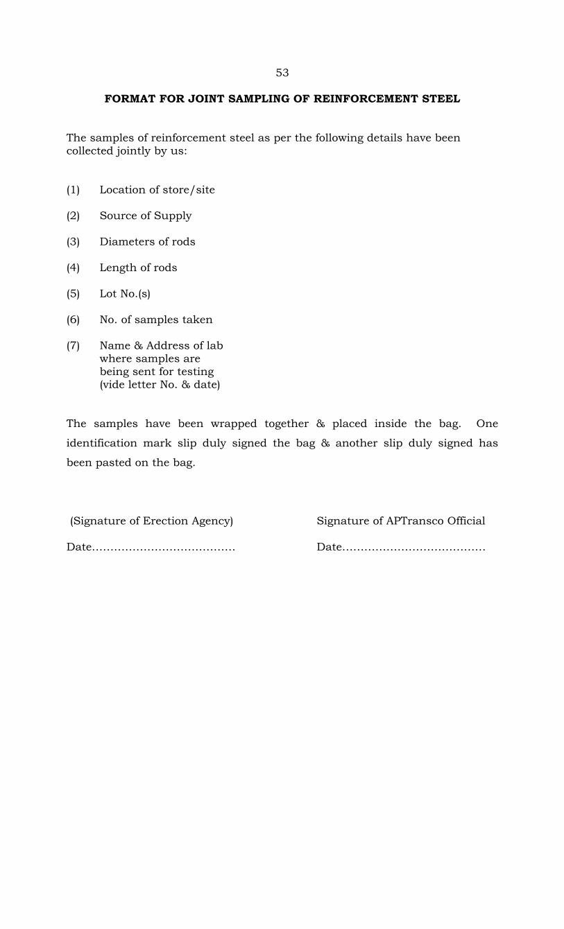
FORMAT FOR JOINT SAMPLING OF REINFORCEMENT STEEL The samples of reinforcement steel as per the following details have been collected jointly by us: (1) Location of store/site (2) Source of Supply (3) Diameters of rods (4) Length of rods (5) Lot No.(s) (6) No. of samples taken (7) Name & Address of lab where samples are being sent for testing (vide letter No. & date) The samples have been wrapped together & placed inside the bag. One
identification mark slip duly signed the bag & another slip duly signed has
been pasted on the bag.
(Signature of Erection Agency) Signature of APTransco Official Date………………………………… Date…………………………………

54
FORMAT FOR TEST REPORT OF REINGORCEMENT STEEL
Name of Line_______________________________Source of Supply_________________ Name of Executing Agency__________________Sample Ident.Mark_______________ Name & address of Test lab_________________Date_____________________________ Test Report Ref.No.__________________________
Acceptable Limits As per Sl No
Description of test
IS 432 MS Grade I Above 20 mm dia
IS 1786 Fc 415
Manufac. Specn. TMT 415
Test Results Remarks
Chemical Analysis 0.23+/-0.02 Max.
0.30+/-0.02 Max
0.25 +/-0.02 Max
a) Carbon (C) % 0.055+/-0.005 Max
0.06 +/-0.005 Max
0.05+/-0.005 Max
b) Sulphur (S) % 0.055+/-0.005 Max
0.06 +/-0.005 Max
0.05+/-0.005 Max
c) Phosphorous(P) %
0.055+/-0.005 Max
0.06+/-0.005 Max
0.05+/- 0.005 Max
1.
d) Sulphur and % Phosphorous
0.11+/-0.01 Max
0.11+/-0.01 Max
0.10 +/- 0.01 Max
Mechanical Properties
a) 0.2% proof stress N/SQ.MM
250 Min 415 Min. 415 Min
b) Ultimate Tensile Stress N/SQ MM
410 Min 485 Min 500 Min
c) Elongation 23 Min 14.5 Min 22 Min
d) Bend Test No crack/Fracture at Bend visible
No crack/Fracture at Bend visible
No crack/Fracture at Bend visible
2.
e) Rebend Test No crack/Fracture at Bend visible
No crack/Fracture at Bend visible
No crack/Fracture at Bend visible
Note: Latest value may be seen by referring the latest IS code as amended. Certificate: It is certified that test results meet all the requirements as per IS and APTRANSCO Technical specifications. (Signature of the Lab Official) (Signature of Erection Agency) Date:…………………….. Date………………………. Sample is approved (Signature of Powergrid Official) Date…………………………………

CONCRETE CUBE TESTS REGISTER
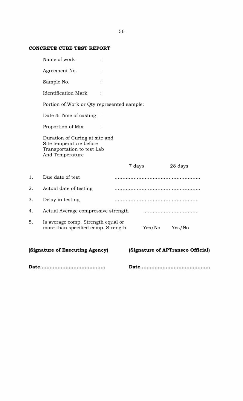
56 CONCRETE CUBE TEST REPORT Name of work : Agreement No. : Sample No. : Identification Mark : Portion of Work or Qty represented sample: Date & Time of casting : Proportion of Mix : Duration of Curing at site and Site temperature before Transportation to test Lab And Temperature 7 days 28 days 1. Due date of test ……………………………………………… 2. Actual date of testing ……………………………………………… 3. Delay in testing …………………………………………….. 4. Actual Average compressive strength …………………………….. 5. Is average comp. Strength equal or more than specified comp. Strength Yes/No Yes/No
(Signature of Executing Agency) (Signature of APTransco Official) Date………………………………….. Date……………………………………..

57
TOWER ERECTION Name of the Line:- Location No:- Name of Contractor:- Type of tower:- Approved Drg.No:- Approved Bill of Material:- Items Checked Results Observations 1. Setting period of foundation is allowed for atleast 14 days (preferably 28 days) as per specification Yes/No 2. All tested tools and plants and safety equipments in working conditions are available at site Yes/No 3. All tower members, Nuts,/bolts are available at site without any damage, bent or rusting and kept on ground serially according to erection sequence Yes/No 4. Benching /revetment, if nay, completed. If not, then program of completion Yes/No 5. Shutdown of power line, if required, is arranged Yes/No 6. Required no.of safety helmets, safety belts & safety shoes are being used. Yes/No 7. First section is completely braced and all plane diagonals are place in proper position Yes/No 8. Guying of tower provided as per approved drawings and norms. Guying to be terminated on firm ground. Yes/No 9. All nuts/bolts, flat/spring washers are provided as per approved drawings Yes/No 10. All bolts to have the nuts facing outside for horizontal or near horizontal bolt connections and downwards for vertical bolt connections (Cl.2.27.5.1.1 of the Technical Specification) Yes/No 11. All the inner contact surfaces at joints painted with zinc rice paint (Cl.2.28.3 of the Technical Specification) Yes/No

58
12. Subsequent section are erected only after complete erection and bracing of previous section Yes/No 13. Any undue stress, bending or damage of member during erection noticed Yes/No 14. Filling of holes or cutting of members during erection observed Yes/No 15. Any heavy hammering of bolt causing damage of threads noticed Yes/No 16. Any substitute of tower member erected, if, yes, member nos. Yes/No 17. Tightening is done progressively from top to bottom Yes/No 18. All bolts at same level on all the four faces tightened simultaneously staring from leg to face on right side by four individuals Yes/No 19. Slipping/running over nuts/bolts are replaced by new ones Yes/No 20. Threaded portion of bolts projected outside of nut is not less than 3 mm and not more Yes/No than 8 mm 21. Punching of threads projected outside is done at three positions on dia Yes/No 22. Half round Tack welding of bolts nuts at two diametrically opposite places upto the bottom Yes/No cross arm and each weld length at least 10mm 22 a) Zinc rich (at least 90% zinc content) on the tack welds on the nuts Yes/No 23. Verticality of tower (1 in 360) is checked with help of Theodolite for both longitudinal & transverse direction. This is within specified Yes/No limits 24. Details of missing member, nut, bolts, etc. Yes/No 25. Mention the tower taking resistance value: Yes/No Certificate: Tower erection is complete in all respects and footing resistance is within permissible limit. FOR CONTRACTOR FOR APTRANSCO Signature……………………… Signature………………………… Name…………………………… Name……………………………… Designation…………………… Designation……………………… Date…………………………….. Date……………………………….

59
TOWER ACCESSORIES Name of the Line:- Location No:- Name of Contractor:- Type of tower:- Approved Drg.No:- Items Checked Results Observations 1. GI bolts and nuts fully tightened and placed as per approved drawing.
a) Number Plate Yes/No b) Phase Plates(set of 3 per circuit) Yes/No c) Danger Plates Yes/No d) Circuit Plate (2 Nos.) Yes/No e) Name plate Yes/No f) Bird guards (Suspension tower only) Yes/No g) Earthing bond (One on suspension
tower and two on tension towers) Yes/No (37/7/0.417 mm Stranded Tinned Copper)
h) Step bolts with spring washers 450 mm spaced on diagonally opposite leg provided 3.5m above the ground Yes/No level to top of the tower
i) Step bolt holes available upto 3.5m Yes/No above ground level.
2. Anti-climbing device including barbed wire, cleats, Barbed wire fixing Galvanized MS member with fully tightened bolts. Yes/No 3. Aviation signals/Paints as per requirement/specification provided where required. Yes/No Certificate: All Tower accessories provided satisfactorily FOR CONTRACTOR FOR APTRANSCO Signature……………………… Signature………………………… Name…………………………… Name……………………………… Designation…………………… Designation……………………… Date…………………………….. Date……………………………….

60
PIPE TYPE EARTHING Name of the Line:- Location No:- Name of Contractor:- Type of tower:- Approved Drg.No:- Items Checked Results Observations 1) Earthing on leg A/1 Yes/No 2) GI Pipe (25mm dia, 3m long) Flat (50x6 mm, 5m Long) with nuts and bolts Yes/No fully tightened and placed as per approved drawing. 3) Placement of Flat along with stub and bending of flat inside the form box as Yes/No per approved drg. 4) Burying of Flat 650mm below ground Yes/No 5) Bore hole (300 mm dia) and depth (3000 mm) Yes/No 6) Gap (150 mm) between the GI pipe bottom end and bottom of the bore hole Yes/No 7) Finely broken coke (grain size not more than 25 mm) and salt (proportion 10:1) Yes/No filled in bore hole around the pipe. 8) Mix of Bentonite powder in 1:6 ratio Yes/No 9) Back filling done Yes/No 10) Earthing resistance measurement (less than 10 Ohm) and if not so, then Yes/No 11) Additional earthing pipe installed. Yes/No 12) Repeat earthing resistance measurement (less than 10 ohm) Yes/No Certificate: Footing resistance within permissible limits. FOR CONTRACTOR FOR APTRANSCO Signature……………………… Signature………………………… Name…………………………… Name……………………………… Designation…………………… Designation……………………… Date………………………….. Date……………………………….

61
COUNTER POISE EARTHING Name of the Line:- Location No:- Name of Contractor:- Type of tower:- Approved Drg.No:- Items Checked Results Observations 1) Earthing provided on all the four legs Yes/No 2) GSS earth wire 7/3.15, 25m long), MS rod (20 mm dia, 6mtrs long) with nuts and bolts fully tightened and Yes/No placed as per approved drg. 3) Burying of GSS earthwire 1000 mm below ground OK/NOT OK 4) MS rod (20mm dia, 600 mm length) at the end of earthwire. Yes/No 5) Back filling done Yes/No 6) Earthing resistance measurement (not less than 10 ohm) Yes/No 7) Additional counter poise installed Yes/No 8) Repeat earthing resistance measurement ( less than 10 ohm) Yes/No Certificate: Footing resistance within permissible limits. FOR CONTRACTOR FOR APTRANSCO Signature……………………… Signature………………………… Name…………………………… Name……………………………… Designation…………………… Designation……………………… Date………………………….. Date……………………………….

62
STRINGING Name of the Line:- section: Loc.No……to Loc. No:- Name of Contractor:- Type of tower:- Approved Tension Stringing Chart:- Approved Drum Schedule:- Items Checked Results Observations 1) Back filling of soil and revetment/ benching wherever required is done. Yes/No 2) Towers are tightened properly and all the members, nut/bolts are provided. Yes/No 3) Tress in the ROW removed to facilitate smooth stringing Yes/No 4) All line materials, tested and calibrated T &P safety equipments and relevant drawings available for stringing. Yes/No 5) Shutdown of Power line/Railway block if required, is arranged. Yes/No 6) Necessary Protection/scaffolding / warning signals provided for Railway/ Yes/No Power line/P&T line/Road crossing. 7) Towers vulnerable for one side load is guyed properly. Yes/No 8) Tower footing resistance is within permissible limit of 10 Ohms. Yes/No

63 B) Paving Out of Earthwire. 1) Work is being carried out with fully safety measures. Yes/No 2) All pulleys fixed on towers for paving out are moving freely. Yes/No 3) Effective communication exists through walkie-talkie and through Yes/No persons with red flags on towers. 4) Earthwire is being constantly checked as it is unwound, Damaged portion, if any, is removed. Yes/No 5) Necessary arrangement have been provided to avoid rubbing of earthwire against hard ground. Yes/No 6) Necessary details of earthwire, M.S.Joints Recorded as per Annex Yes/No CFI & CF II C) Paving Out of Conductor 1) Work is being carried out with full safety measures Yes/No 2) Conductor drums are placed properly to avoid bird caging. Yes/No 3) Sequence of paving out is such that to avoid unbalancing of load on tower Yes/No 4) Details of insulators and fitting are recorded. As per Annex CF III and Yes/No Annex CF IV. 5) Travelers fixed on towers are moving freely Yes/No 6) Effective communication exists through Walkie-Talkie and through persons with red flags on towers. Yes/No 7) Conductors is checked continuously as it is unwound from drum. Damaged portion if any, is removed/repaired. Yes/No 8) Travelers fixed on towers are
moving freely Yes/No 9) Effective communication exists through walkie-talkie and through persons with
red flags on towers. Yes/No 10) Conductors is checked continuously as it is unwound from drum. Damaged portion if any, is removed/repaired. Yes/No

64 11) Proper arrangements made to avoid rubbing of conductor on ground/hard Yes/No surfaces. 12) Details of conductor M.S.J. /repair sleeve are recorded as per Annex CF II Yes/No and Annex CF II. D) Final Sagging & Tensioning of Earthwire & Conductor 1) Sag Board is fixed correctly after taking into account length of suspension Yes/No clamp/fittings in case of Earthwire and Suspension insulator string in case of conductor. 2) Sag/Tension is measured correctly at prevailing temperature. Details recorded Yes/No as per Annex CF V. 3) Minimum Ground Clearance, clearance over Power line/Railway Line/River Yes/No crossing/Telecom/Road are as per specification. E) Dead Ending 1) Subsequent to final sagging, dead end
work is done marking the length of
conductor corresponding to single/double
tension string for conductor and dead end Yes/No
clamp for ground wire.
2) Corresponding to dead end clamp drawing,
the aluminum strands over the steel core
are cut and steel portion and aluminum
portion of dead end clamp is compressed
as applicable to conductor and only steel
clamps for ground wire. Yes/No
3) Clipping offsets marked with felt tip
marker and not with sharp instruments
denting conductor stands. Yes/No

65
4) For power line crossing section precautions taken before clipping. Yes/No
i) The existing power line conductors are grounded.
ii) No person in series with the potential electric circuit.
5) Prior to installation/removing dead
end jumper on structure earthing done
on both sides of the work and Yes/No
connected to structure.
6) Suspension clamps and dampers installed with in
36 hours after final connected to structure Yes/No
7) Center of the body (cushioned) and clamp
body of AGS clamp coincides with the Yes/No
armor rods, marked point on the conductor.
8) No difference in length between the longest Yes/No
and shortest rod when applied not to
exceed 13 mm.
F) Conductor Fittings and Attachments 1) Spacers and dampers fixed immediately but with in 24 hours of conductor clamping as per manufactures recommendations. Yes/No 2)a) Whether spacer cars/cycles are fixed with meter counters for measuring intra-spacing of spacers/ spacer dampers during placement and if no. Yes/No b) How the distance between spacers/spacer damper in measured. Yes/No 3) Vibration dampers for ground wire installed as per manufactures recommendations immediately but within 24 hours of clipping. Yes/No 4) Span marker on ground wire, if required, installed on ground wire after clamping and fixing of vibration dampers on the ground wire. Yes/No
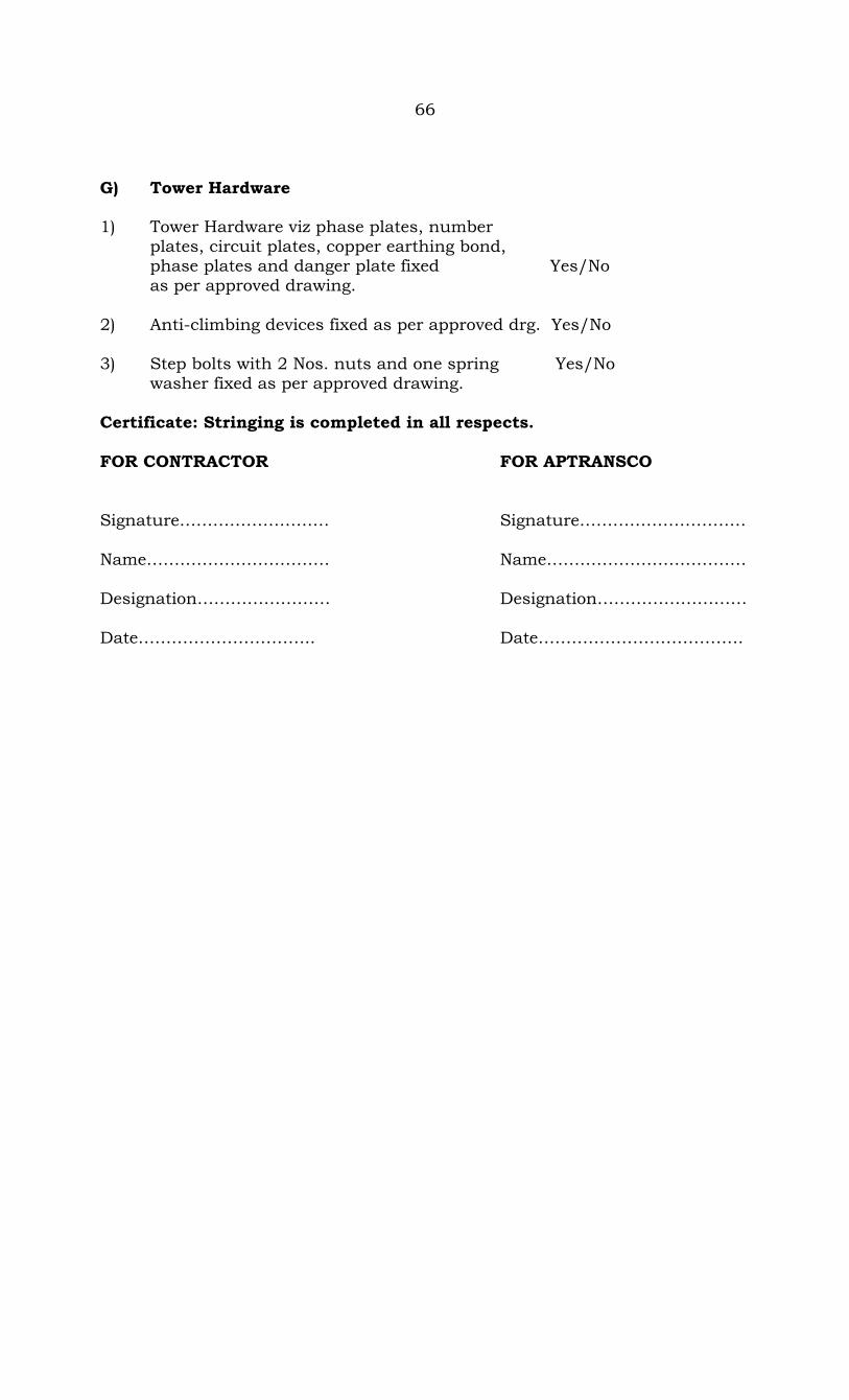
66 G) Tower Hardware 1) Tower Hardware viz phase plates, number plates, circuit plates, copper earthing bond, phase plates and danger plate fixed Yes/No as per approved drawing. 2) Anti-climbing devices fixed as per approved drg. Yes/No 3) Step bolts with 2 Nos. nuts and one spring Yes/No washer fixed as per approved drawing. Certificate: Stringing is completed in all respects. FOR CONTRACTOR FOR APTRANSCO Signature……………………… Signature………………………… Name…………………………… Name……………………………… Designation…………………… Designation……………………… Date………………………….. Date……………………………….
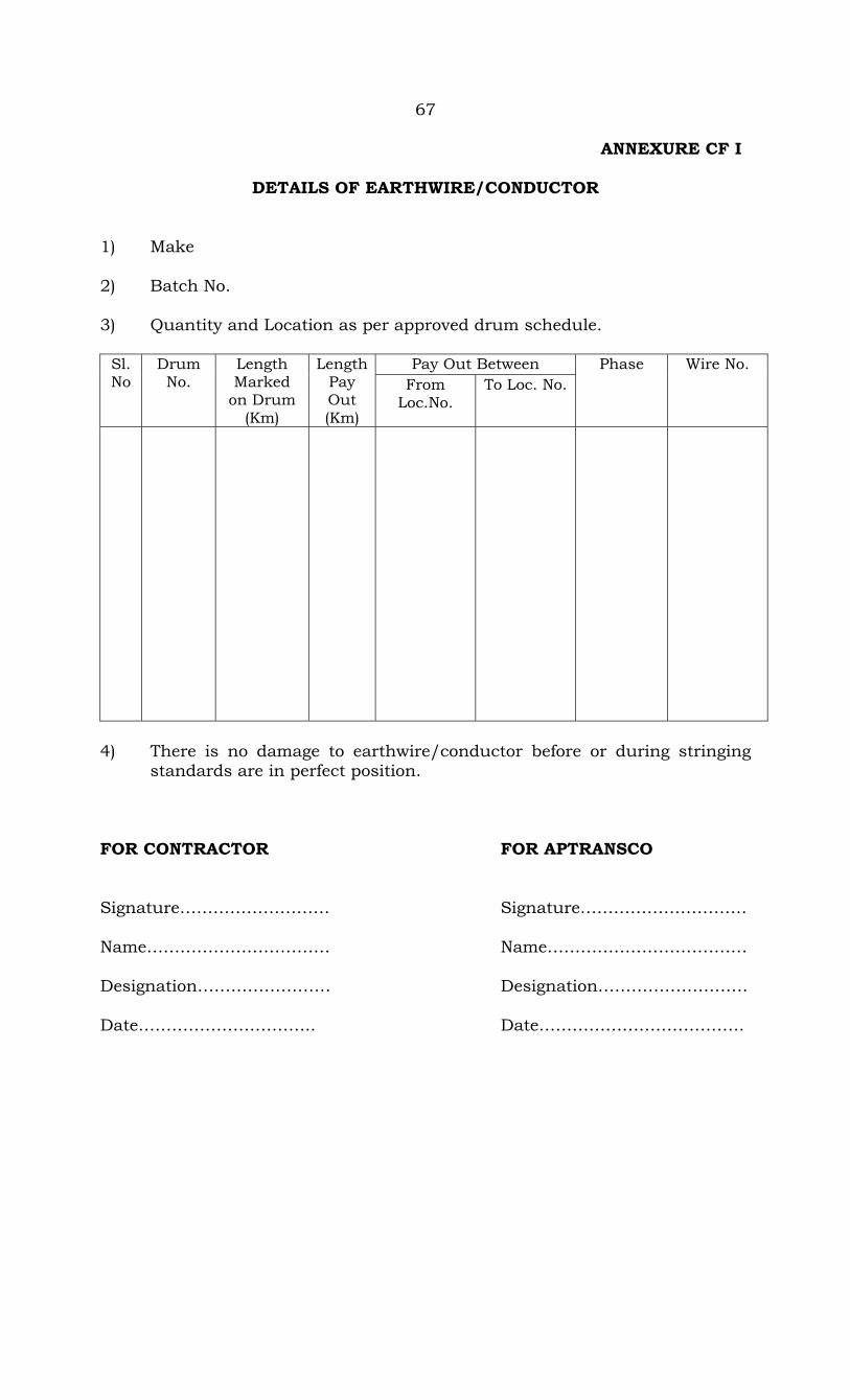
67 ANNEXURE CF I
DETAILS OF EARTHWIRE/CONDUCTOR 1) Make 2) Batch No. 3) Quantity and Location as per approved drum schedule.
Pay Out Between Sl.No
Drum No.
Length Marked
on Drum (Km)
Length Pay Out (Km)
From Loc.No.
To Loc. No. Phase Wire No.
4) There is no damage to earthwire/conductor before or during stringing standards are in perfect position. FOR CONTRACTOR FOR APTRANSCO Signature……………………… Signature………………………… Name…………………………… Name……………………………… Designation…………………… Designation……………………… Date………………………….. Date……………………………….
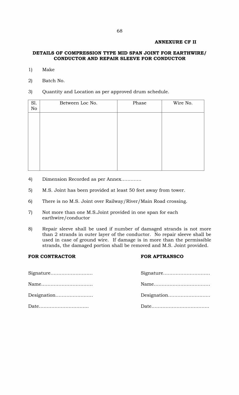
68 ANNEXURE CF II
DETAILS OF COMPRESSION TYPE MID SPAN JOINT FOR EARTHWIRE/ CONDUCTOR AND REPAIR SLEEVE FOR CONDUCTOR
1) Make 2) Batch No. 3) Quantity and Location as per approved drum schedule. Sl.No
Between Loc No. Phase Wire No.
4) Dimension Recorded as per Annex…………. 5) M.S. Joint has been provided at least 50 feet away from tower. 6) There is no M.S. Joint over Railway/River/Main Road crossing. 7) Not more than one M.S.Joint provided in one span for each earthwire/conductor 8) Repair sleeve shall be used if number of damaged strands is not more than 2 strands in outer layer of the conductor. No repair sleeve shall be used in case of ground wire. If damage is in more than the permissible strands, the damaged portion shall be removed and M.S. Joint provided. FOR CONTRACTOR FOR APTRANSCO Signature……………………… Signature………………………… Name…………………………… Name……………………………… Designation…………………… Designation……………………… Date………………………….. Date……………………………….
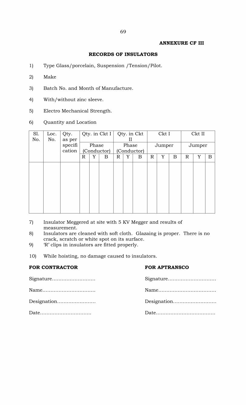
69 ANNEXURE CF III
RECORDS OF INSULATORS 1) Type Glass/porcelain, Suspension /Tension/Pilot. 2) Make 3) Batch No. and Month of Manufacture. 4) With/without zinc sleeve. 5) Electro Mechanical Strength. 6) Quantity and Location
Qty. in Ckt I Qty. in Ckt II
Ckt I Ckt II
Phase (Conductor)
Phase (Conductor)
Jumper Jumper
Sl. No.
Loc. No.
Qty. as per specification
R Y B R Y B R Y B R Y B
7) Insulator Meggered at site with 5 KV Megger and results of measurement. 8) Insulators are cleaned with soft cloth. Glazaing is proper. There is no crack, scratch or white spot on its surface. 9) ‘R’ clips in insulators are fitted properly. 10) While hoisting, no damage caused to insulators. FOR CONTRACTOR FOR APTRANSCO Signature……………………… Signature………………………… Name…………………………… Name……………………………… Designation…………………… Designation……………………… Date………………………….. Date……………………………….
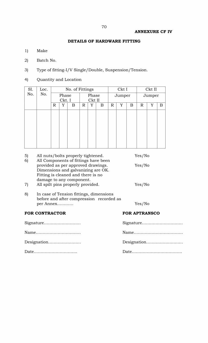
70 ANNEXURE CF IV
DETAILS OF HARDWARE FITTING 1) Make 2) Batch No. 3) Type of fitting-I/V Single/Double, Suspension/Tension. 4) Quantity and Location
No. of Fittings Ckt I Ckt II Phase Ckt. I
Phase Ckt II
Jumper Jumper Sl. No.
Loc. No.
R Y B R Y B R Y B R Y B
5) All nuts/bolts properly tightened. Yes/No 6) All Components of fittings have been provided as per approved drawings. Yes/No Dimensions and galvanizing are OK. Fitting is cleaned and there is no damage to any component. 7) All spilt pins properly provided. Yes/No 8) In case of Tension fittings, dimensions before and after compression recorded as per Annex………… Yes/No FOR CONTRACTOR FOR APTRANSCO Signature……………………… Signature………………………… Name…………………………… Name……………………………… Designation…………………… Designation……………………… Date………………………….. Date……………………………….

71 ANNEXURE CF V
SAG MEASUREMENT FOR CONDUCTOR 1) Sag Board/dynamometer fixed between Loc No. and 2) Temperature ………………..oC 3) Measurement of Sag/Tension.
As per Sag/Tension Chart
Actual Sag /Tension Item Phase/Wire No.
Initial Sagging
Final Sagging
Initial Sagging
Final Sagging
Sag
Tension
4) During paying out/rough sagging, tension in conductor was as per technical specifications (50% of sagging tension). 5) Calibration certification for dynamometer checked. Yes/No 6) Vertical clearance between top conductor and earth wire at minimum clearance point along the span is indicated as--------------------------- FOR CONTRACTOR FOR APTRANSCO Signature……………………… Signature………………………… Name…………………………… Name……………………………… Designation…………………… Designation……………………… Date………………………….. Date……………………………….
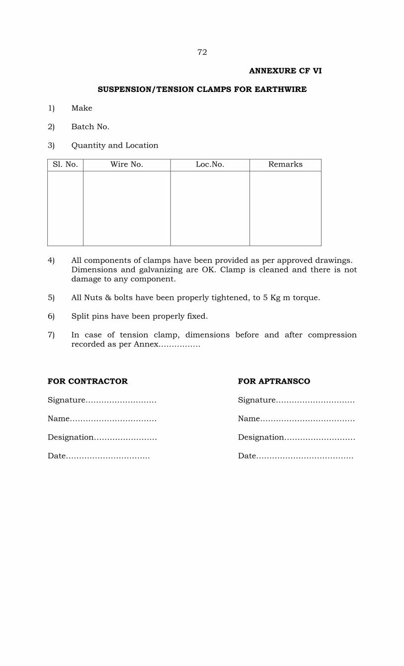
72
ANNEXURE CF VI
SUSPENSION/TENSION CLAMPS FOR EARTHWIRE 1) Make 2) Batch No. 3) Quantity and Location
Sl. No. Wire No. Loc.No. Remarks
4) All components of clamps have been provided as per approved drawings. Dimensions and galvanizing are OK. Clamp is cleaned and there is not damage to any component. 5) All Nuts & bolts have been properly tightened, to 5 Kg m torque. 6) Split pins have been properly fixed. 7) In case of tension clamp, dimensions before and after compression recorded as per Annex……………. FOR CONTRACTOR FOR APTRANSCO Signature……………………… Signature………………………… Name…………………………… Name……………………………… Designation…………………… Designation……………………… Date………………………….. Date……………………………….

73
ANNEXURE CF VII
RECORDS OF V.D. FOR EARTHWIRE AND CONDUCTOR 1) Make 2) Batch No. 3) Quantity and Location Sl. No. Fixed on
Loc.No. (Right side)
Fixed on Loc.No. (Left side)
Phase/Wire No.
No. of V.D.
4) All components of V.D. have been provided as per approved drawings. Dimensions and galvanizing are OK. Clamp is cleaned and there is not damage to any component including messenger wire. 5) All Nuts & bolts have been properly tightened, to 4 Kg m torque. 6) V.D. Fixed as per approved placement chart. FOR CONTRACTOR FOR APTRANSCO Signature……………………… Signature………………………… Name…………………………… Name……………………………… Designation…………………… Designation……………………… Date………………………….. Date……………………………….

74
ANNEXURE CF VIII
RECORDS OF LINE SPACER/SPACER DAMPER/JUMPER SPACER 1) Make 2) Batch No. 3) Quantity and Location Sl. No. Span/Loc.No. Phase No.of spacer
4) All components of V.D. have been provided as per approved drawings. Dimensions and galvanizing are OK. Clamp is cleaned and there is not damage to any component including messenger wire. 5) All Nuts & bolts have been properly tightened, to 4 Kg m torque. 6) Spacer/Spacer damper Fixed as per approved placement chart.
(Copy enclosed.)
FOR CONTRACTOR FOR APTRANSCO Signature……………………… Signature………………………… Name…………………………… Name……………………………… Designation…………………… Designation……………………… Date………………………….. Date……………………………….

75
ANNEXURE CF IX (1)
The Dimensions of Tension Clamp suitable for (Zebra) Moose (AAAC Panther, ACSR Panther, AAAC Moose)
1) Loc.No. 2) Span……………………….Loc Nos…………………..to……………….. 3) Approved Drg.No. EMI/DE/710LT4-31.77 4) Details of Dimensions
Steel Portion Aluminum Portion
As per Drg. Actual As per Drg. Actual
Before Comp. After Comp. After Comp. Before Comp
After Comp. After Comp.
Length
Outer dia
C-C F-F Length
C-C F-F Length
Outer dia
Length
C-C F-F Length
C-C F-F
Dead End
Jumper
Leg
300 mm
21 ± 1
--
20.2± 0.5
17.5 ± 5
610
230
54± 1
54± 0.5
640
--
53± 0.5 53± 0.5
46± 0.5 46± 0.5
C-C : Corner to Corner Distance F-F : Face to Face Distance For Jumper leg the dimensions before and after compression may be obtained from the supplier and checked.

76
5) Bores in the sleeves are perfectly clean. 6) The following may be checked as per approved drawing.
a) Marking and cutting b) Correct sizes of dies c) Centering & fixing of sleeves d) Fixing of all the components i.e., Aluminium end pipes, hole plugs
etc. e) Compression of sleeves at specified pressure.
7) All the sharp edges have been filled after compression. 8) There is no crack, bend or any damage to joint after compression. FOR CONTRACTOR FOR APTRANSCO Signature……………………… Signature………………………… Name…………………………… Name……………………………… Designation…………………… Designation……………………… Date………………………….. Date……………………………….
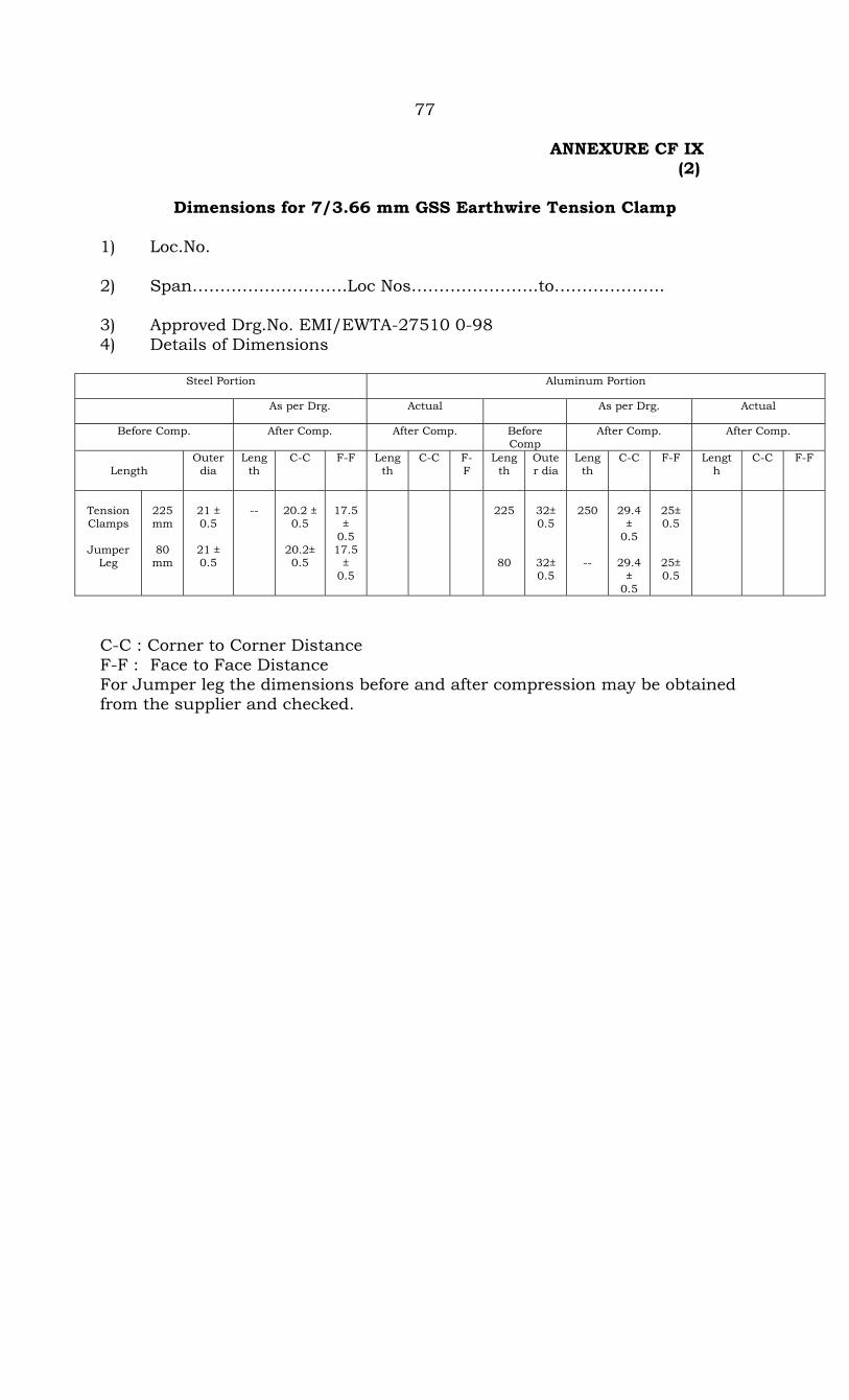
77 ANNEXURE CF IX (2)
Dimensions for 7/3.66 mm GSS Earthwire Tension Clamp
1) Loc.No. 2) Span……………………….Loc Nos…………………..to……………….. 3) Approved Drg.No. EMI/EWTA-27510 0-98 4) Details of Dimensions
Steel Portion Aluminum Portion
As per Drg. Actual As per Drg. Actual
Before Comp. After Comp. After Comp. Before Comp
After Comp. After Comp.
Length
Outer dia
Length
C-C F-F Length
C-C F-F
Length
Outer dia
Length
C-C F-F Length
C-C F-F
Tension Clamps
Jumper
Leg
225 mm
80
mm
21 ± 0.5
21 ± 0.5
--
20.2 ±
0.5
20.2± 0.5
17.5
± 0.5 17.5
± 0.5
225
80
32± 0.5
32± 0.5
250
--
29.4
± 0.5
29.4
± 0.5
25± 0.5
25±0.5
C-C : Corner to Corner Distance F-F : Face to Face Distance For Jumper leg the dimensions before and after compression may be obtained from the supplier and checked.

78 5) Bores in the sleeves are perfectly clean. 6) The following may be checked as per approved drawing.
a) Marking and cutting b) Correct sizes of dies c) Centering & fixing of sleeves d) Fixing of all the components i.e., Aluminium end pipes, hole plugs
etc. e) Compression of sleeves at specified pressure.
7) All the sharp edges have been filled after compression. 8) There is no crack, bend or any damage to joint after compression. FOR CONTRACTOR FOR APTRANSCO Signature……………………… Signature………………………… Name…………………………… Name……………………………… Designation…………………… Designation……………………… Date………………………….. Date……………………………….
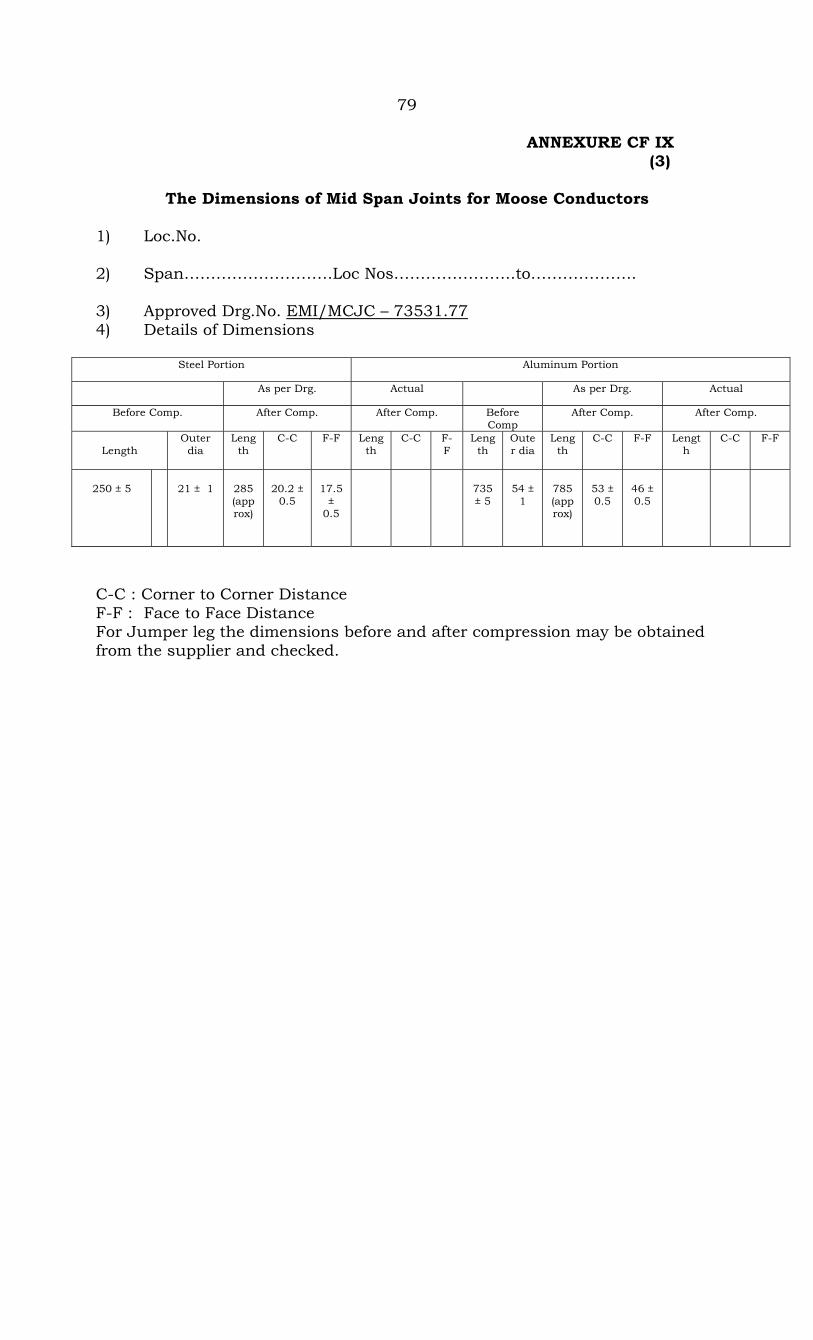
79 ANNEXURE CF IX (3)
The Dimensions of Mid Span Joints for Moose Conductors 1) Loc.No. 2) Span……………………….Loc Nos…………………..to……………….. 3) Approved Drg.No. EMI/MCJC – 73531.77 4) Details of Dimensions
Steel Portion Aluminum Portion
As per Drg. Actual As per Drg. Actual
Before Comp. After Comp. After Comp. Before Comp
After Comp. After Comp.
Length
Outer dia
Length
C-C F-F Length
C-C F-F
Length
Outer dia
Length
C-C F-F Length
C-C F-F
250 ± 5
21 ± 1
285 (approx)
20.2 ±
0.5
17.5
± 0.5
735 ± 5
54 ±
1
785 (approx)
53 ± 0.5
46 ± 0.5
C-C : Corner to Corner Distance F-F : Face to Face Distance For Jumper leg the dimensions before and after compression may be obtained from the supplier and checked.
80
5) Bores in the sleeves are perfectly clean. 6) The following may be checked as per approved drawing.
a) Marking and cutting b) Correct sizes of dies c) Centering & fixing of sleeves d) Fixing of all the components i.e., Aluminium end pipes, hole plugs
etc. e) Compression of sleeves at specified pressure.
7) All the sharp edges have been filled after compression. 8) There is no crack, bend or any damage to joint after compression. FOR CONTRACTOR FOR APTRANSCO Signature……………………… Signature………………………… Name…………………………… Name……………………………… Designation…………………… Designation……………………… Date………………………….. Date……………………………….
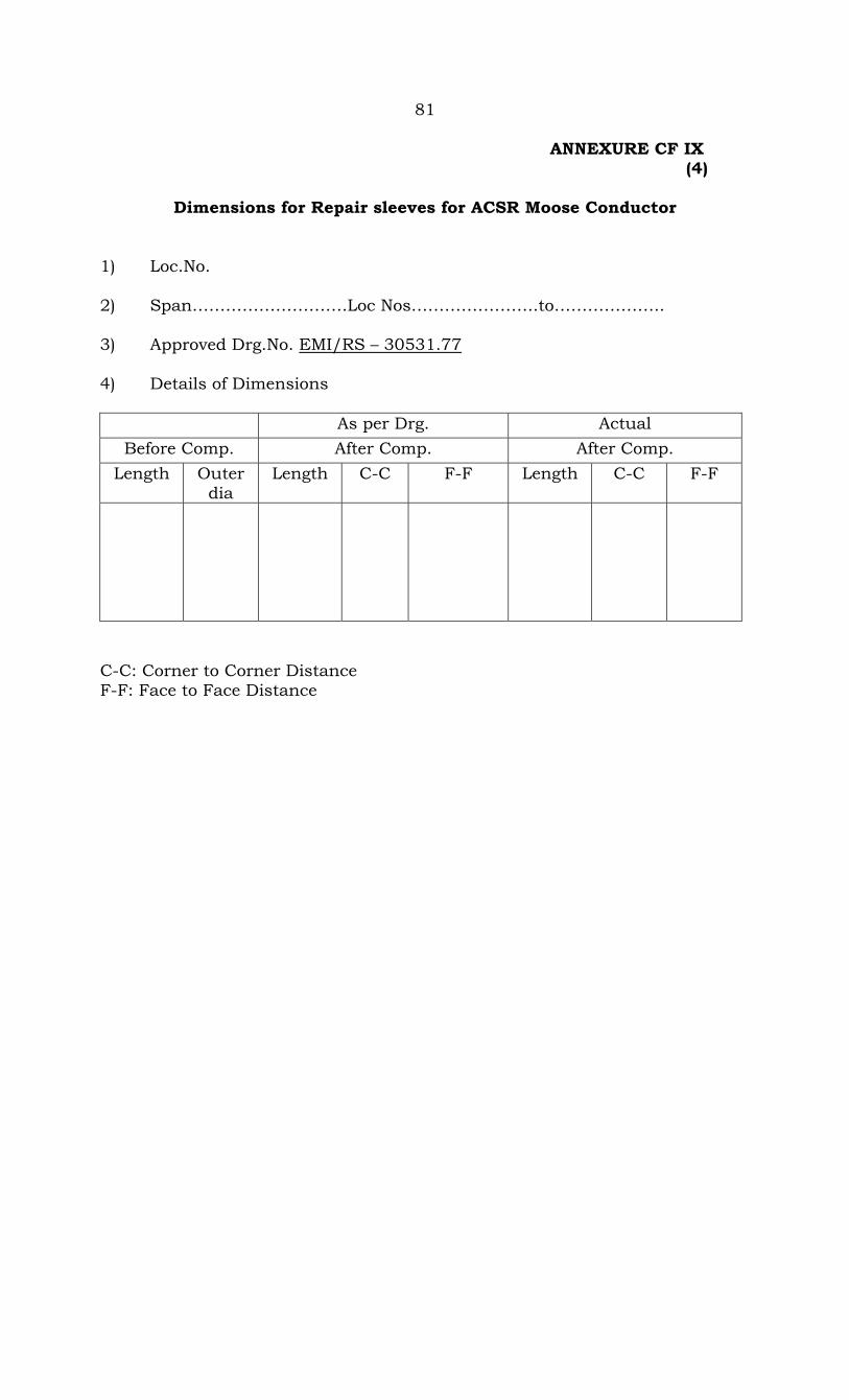
81 ANNEXURE CF IX (4)
Dimensions for Repair sleeves for ACSR Moose Conductor 1) Loc.No. 2) Span……………………….Loc Nos…………………..to……………….. 3) Approved Drg.No. EMI/RS – 30531.77 4) Details of Dimensions
As per Drg. Actual Before Comp. After Comp. After Comp.
Length Outer dia
Length C-C F-F Length C-C F-F
C-C: Corner to Corner Distance F-F: Face to Face Distance
82
5) Bores in the sleeves are perfectly clean. 6) The following may be checked as per approved drawing.
a) Marking and cutting b) Correct sizes of dies c) Centering & fixing of sleeves d) Fixing of all the components i.e., Aluminium end pipes, hole plugs
etc. e) Compression of sleeves at specified pressure.
7) All the sharp edges have been filled after compression. 8) There is no crack, bend or any damage to joint after compression. FOR CONTRACTOR FOR APTRANSCO Signature……………………… Signature………………………… Name…………………………… Name……………………………… Designation…………………… Designation……………………… Date………………………….. Date……………………………….

83 ANNEXURE CF IX (5)
Dimensions for Mid Span Joints for 7/3.15 mm GSS Earthwire 1) Loc.No. 2) Span……………………….Loc Nos…………………..to……………….. 3) Approved Drg.No. 4) Details of Dimensions
Steel Portion Aluminum Portion
As per Drg. Actual As per Drg. Actual
Before Comp. After Comp. After Comp. Before Comp
After Comp. After Comp.
Length
Outer dia
Length
C-C F-F Length
C-C F-F
Length
Outer dia
Length
C-C F-F Length
C-C F-F
C-C : Corner to Corner Distance F-F : Face to Face Distance
84
5) Bores in the sleeves are perfectly clean. 6) The following may be checked as per approved drawing.
a) Marking and cutting b) Correct sizes of dies c) Centering & fixing of sleeves d) Fixing of all the components i.e., Aluminium end pipes, hole plugs
etc. e) Compression of sleeves at specified pressure.
7) All the sharp edges have been filled after compression. 8) There is no crack, bend or any damage to joint after compression. FOR CONTRACTOR FOR APTRANSCO Signature……………………… Signature………………………… Name…………………………… Name……………………………… Designation…………………… Designation………………………
Date………………………….. Date……………………………….
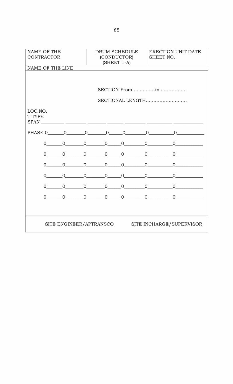
85 NAME OF THE CONTRACTOR
DRUM SCHEDULE (CONDUCTOR) (SHEET 1-A)
ERECTION UNIT DATE SHEET NO.
NAME OF THE LINE
SECTION From……………to……………… SECTIONAL LENGTH……………………… LOC.NO. T.TYPE SPAN __________ _________ ________ _______ _________ ___________ _____________ PHASE 0_______0________0________0______0_________0___________0____________ 0_______0________0________0______0_________0___________0____________ 0_______0________0________0______0_________0___________0____________ 0_______0________0________0______0_________0___________0____________
0_______0________0________0______0_________0___________0____________ 0_______0________0________0______0_________0___________0____________ 0_______0________0________0______0_________0___________0____________
SITE ENGINEER/APTRANSCO SITE INCHARGE/SUPERVISOR

86
NAME OF THE CONTRACTOR
DRUM SCHEDULE (CONDUCTOR) (SHEET 1-A)
ERECTION UNIT DATE SHEET NO.
NAME OF THE LINE
Sl.N
o.
Dru
m N
o.
Mak
e
Len
gth
(M
trs.
)
Phas
e
Payi
ng
out
betw
een
Lo
cs
Qu
anti
ty
Con
sum
ed
Rem
arks
Bal
ance
Bit
Le
ngt
h
Bit
to
be
use
d at

87
NAME OF THE CONTRACTOR
DRUM SCHEDULE (CONDUCTOR) (SHEET 1-A)
ERECTION UNIT DATE SHEET NO.
NAME OF THE LINE SECTION From……………to………………
SECTIONAL LENGTH……………………… LOC.NO. T.TYPE SPAN __________ _________ ________ _______ _________ ___________ _____________ PHASE 0_______0________0________0______0_________0___________0____________
0_______0________0________0______0_________0___________0____________
Sl.N
o.
Dru
m N
o.
Mak
e
Len
gth
(M
trs.
)
Phas
e
Payi
ng
out
betw
een
Lo
cs
Qu
anti
ty
Con
sum
ed
Bal
ance
Bit
Le
ngt
h
Bit
to
be
use
d at
Rem
arks
SITE ENGINEER/APTRANSCO SITE INCHARGE/SUPERVISOR