ARGOLUX AU S3M2 - ReeR SpA · Test input, which allows the ... Operating temperature °C 0 ÷ 55...
15
PHOTOELECTRIC BARRIER ULISSE UPC INSTALLAZIONE, USO E MANUTENZIONE INSTALLATION, USE AND MAINTENANCE INSTALLATION UND WARTUNGSANLEITUNG
Transcript of ARGOLUX AU S3M2 - ReeR SpA · Test input, which allows the ... Operating temperature °C 0 ÷ 55...
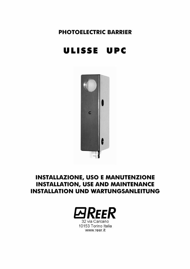
PHOTOELECTRIC BARRIER
ULISSE UPC
IINNSSTTAALLLLAAZZIIOONNEE,, UUSSOO EE MMAANNUUTTEENNZZIIOONNEE IINNSSTTAALLLLAATTIIOONN,, UUSSEE AANNDD MMAAIINNTTEENNAANNCCEE
IINNSSTTAALLLLAATTIIOONN UUNNDD WWAARRTTUUNNGGSSAANNLLEEIITTUUNNGG
8540411 24/03/2016 Rev.7 1
PHOTOELECTRIC
BARRIER
ULISSE UPC
INSTALLATION, USE AND MAINTENANCE
CONTENTS
FEATURES ................................................................................................................................. 2
OPERATION ............................................................................................................................. 3
USE AS A PART OF A SAFETY SYSTEM ....................................................................................... 3
NEW SAFETY PARAMETERS FOR TYPE 2 BARRIERS AND MANDATORY LABELLING ................... 3
TECHNICAL DATA ..................................................................................................................... 4
INDICATORS ............................................................................................................................. 5
INSTALLATION .......................................................................................................................... 6
Preacautions and mechanical installation ................................................................... 6
Distance from reflecting surfaces ............................................................................... 6
Multiple systems. ..................................................................................................... 7
Safety distance and positioning ................................................................................. 7
ELECTRICAL CONNECTIONS ................................................................................................... 8
CHECKS AND MAINTENANCE ................................................................................................. 9
OPERATING FAULTS. ................................................................................................................ 9
MECHANICAL DIMENSIONS ................................................................................................... 10
IDENTIFICATION LABELS ......................................................................................................... 11
S/N field codification: ............................................................................................ 11
ORDERING CODES AND SPARE PARTS................................................................................... 11
Ordering codes ..................................................................................................... 11
Spare parts ........................................................................................................... 11
WARRANTY ............................................................................................................................. 12
2 8540411 24/03/2016 Rev.7
CAUTION
Ulisse UPC photocell meets the requirements of a type 2 safety device only if
connected with a certified safety interface in accordance with the Machine
Directive 2006/42/EC and with the standard IEC 61496-1, 2. ReeR S.p.A. will
not be liable for any consequence arising from the use of Ulisse UPC photocells
under conditions differing from the ones described above.
FEATURES
Through-beam barrier type photocell
Robust and compact metal housing with flat glass lenses. Ulisse is therefore vibration-
resistant, as well as easy to clean and immune to the electrostatic attraction of dust. This
makes it particularly suitable for the use in the textile industry environment.
Power supply lines protected towards reverse polarity connections.
PNP type switching output protected towards short-circuit.
No false triggering on power-up.
Test input, which allows the sensor to be tested by a remote controller
Suitable for risk applications according to IEC 61496 (see par. "Use as a part of a
safety system").
Led indicators on both emitter and receiver.
Complies with 2014/30/EU ("EMC Directive") and 2014/35/EU ("Low voltage
directive").
Miniature M8 connector.
Ulisse is also available in the UNC version which, in connection with
the control units REER AUSX and AUSXM, can form a type two,
through-beam, single or double-beam safety light barrier.
8540411 24/03/2016 Rev.7 3
OPERATION
When the optical path of the infrared beam linking the emitter with the receiver is totally
interrupted the receiver output switches off and remains in the off-state.
When the beam is released again, the output switches to the on-state.
The correct operation of the photocell is checked by means of the test function, which
permits the measurement the response time: if a low level signal is applied to the emitter's
test input the beam emission is interrupted and therefore the receiver goes to the off-state
within a time approximately equal to 8 msec in a normal operating condition.
USE AS A PART OF A SAFETY SYSTEM
Ulisse UPC has been third-party certified as being in compliance with the requirements of
IEC 61496 which are relevant for a photoelectric sensor (see enclosed certificate).
Thanks to the test input on the emitter assembly the Ulisse UPC photocells can be connected
with safety devices (e.g. safety-related parts of control systems) measuring their response
time.
Ulisse UPC can therefore be used as a single beam photoelectric detector within a Type 2
safety system for the protection of human beings exposed to hazardous machines or areas if
the overall safety system has been certified as being in compliance with the safety
requirements of the "Machine" Directive 2006/42/EC or of a relevant IEC or European
Standard (IEC or EN 61496).
No other use of Ulisse UPC as a safety device is admitted. REER will not be liable for any
consequence arising from the use of Ulisse photocells under conditions differing from the
ones described above.
NEW SAFETY PARAMETERS FOR TYPE 2 BARRIERS
AND MANDATORY LABELLING
With the publication of Edition 3 of the harmonized EN 61496-1 standard it is no longer
possible to use a Type 2 safety light barrier for safety functions assessed as SIL 2 / PL d.
If a safety level of SIL 2 / PL d (or higher) is required and it is nevertheless intended to use a
safety light barrier, then it will be necessary to use a Type 4 safety light barrier.
This regulatory requirement derives from the fact that the reduction of risk that can be
obtained via a photoelectric safety barrier is not only a function of the safety level of its
electronic parts, but is also determined by its systematic capabilities (for example:
environmental influences, EMC, optical performance and detection principle).
The systematic capability of a Type 2 photoelectric barrier may in fact not be sufficient to
ensure adequate risk reduction for SIL 2 / PLc applications.
The standard also establishes that the labelling of Type 2 safety barriers must indicate such
limitation to SIL 1 / PLc.
The PFHd values declared for the electronic control part of the device, on the other hand,
are not limited and therefore it is possible to use the PFHd value provided by the
manufacturer of the device in the global assessment of the safety function, even if it exceeds
the SIL 1 / PLd range.

4 8540411 24/03/2016 Rev.7
TECHNICAL DATA
MODEL UPCE-EMITTER UPCR-RECEIVER
Safety level Type 2 - SILCL 1 - PL c - Cat.2
(when used with the AUSX, AUSXM units)
PFH (IEC 62061) 8,04E-09
DCavg (ISO 13849-1) 90%
MTTF (ISO 13849-1) 100
CCF (ISO 13849-1) 80%
Scanning range m 0,8 ÷ 6
Minimum detectable item mm 8
Immunity to ambient light lx > 10.000 (solar)
Emission angle ± 5°
Emission wavelenght nm 880 (modulated infrared)
Response time ms < 8
Power supply Vdc 24 ± 20%
Power comsumption
at 24 Vdc W 0,7 0,4
Output PNP 100 mA max
Light on
Test input PNP active low
Connections M8 Connector
Operating temperature °C 0 ÷ 55 (with no condensate and no frosting)
Protection degree IP 65
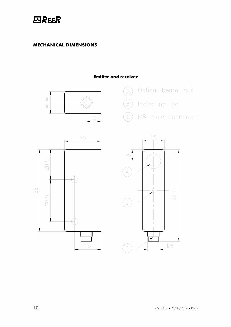
Dimensions
Width 15
Depth mm 25
Height 63
Weight g 40
8540411 24/03/2016 Rev.7 5
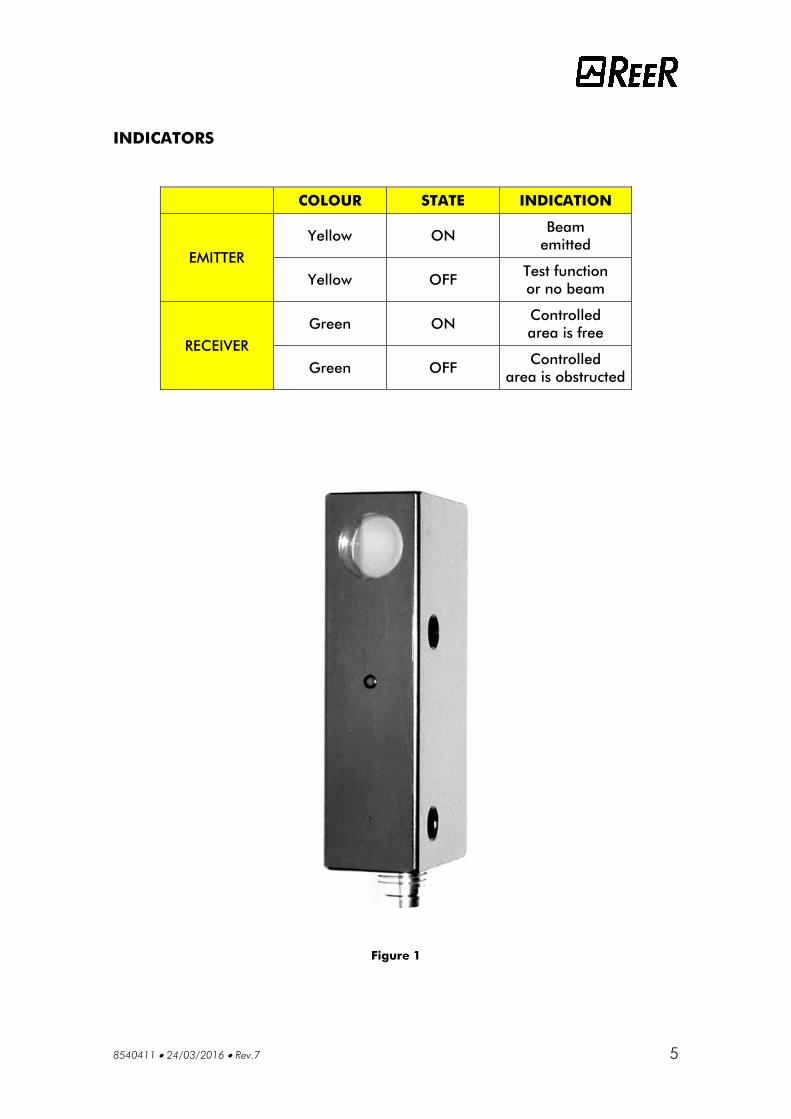
INDICATORS
COLOUR STATE INDICATION
EMITTER
Yellow ON Beam
emitted
Yellow OFF Test function
or no beam
RECEIVER
Green ON Controlled
area is free
Green OFF Controlled
area is obstructed
Figure 1

6 8540411 24/03/2016 Rev.7
INSTALLATION
Preacautions and mechanical installation
Before installation please consider that:
Neither the emitter nor the receiver have to be placed in the proximity of high-intensity
or blinking light sources
If the system is installed in places undergoing sudden temperature variations it is
necessary to adopt the customary measures to prevent the formation of condensate on
the lenses, as this might impair their detection capability.
The emitter and the receiver must be installed one in front of the other at a distance which
must not exceed the operating range.
A good alignment between the emitter and the receiver is necessary for the correct
operation of the photocell. The green led on the receiver, indicating a sufficient
intensity of the received signal, can help for this purpose.
Distance from reflecting surfaces
Reflecting surfaces located next to the photocell(s) may cause spurious reflections that would
close the optical path between the emitter and the receiver and inhibit the system's
detection capability (fig. 2).
Having completed the installation, check for the presence of reflecting surfaces which might
intercept the beam, first in the centre and then in the proximity of the emitter and the
receiver. If any object is intercepted, the green led located on the receiver (fig. 1) must never
light up.
Figure 2
8540411 24/03/2016 Rev.7 7
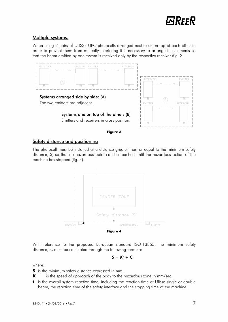
Multiple systems.
When using 2 pairs of ULISSE UPC photocells arranged next to or on top of each other in
order to prevent them from mutually interfering it is necessary to arrange the elements so
that the beam emitted by one system is received only by the respective receiver (fig. 3).
Figure 3
Safety distance and positioning
The photocell must be installed at a distance greater than or equal to the minimum safety
distance, S, so that no hazardous point can be reached until the hazardous action of the
machine has stopped (fig. 4).
Figure 4
With reference to the proposed European standard ISO 13855, the minimum safety
distance, S, must be calculated through the following formula:
S = Kt + C
where:
S is the minimum safety distance expressed in mm.
K is the speed of approach of the body to the hazardous zone in mm/sec.
t is the overall system reaction time, including the reaction time of Ulisse single or double
beam, the reaction time of the safety interface and the stopping time of the machine.
Systems arranged side by side: (A)
The two emitters are adjacent.
Systems one on top of the other: (B)
Emitters and receivers in cross position.

8 8540411 24/03/2016 Rev.7
ELECTRICAL CONNECTIONS
Ulisse UPC is fitted with a 3 pin M8 male connector (fig. 5).
It is possible to use 5 m or 15 m cables equipped with an M8 female connector, either
straight or at 90°, which can be supplied upon request.
Figure 5
Before making the connections, make sure that the mains voltage value corresponds
with the one indicated in the technical data.
Use a PELV type 24 Vdc 20% power supply (e.g. through an insulating transformer
complying with CEI EN 61558).
The connector pin n° 3 is electrically connected with the metal case of the
photocell. If the photocell has to be linked to a metal part of the
machine which is connected with the ground, the return line of the 24
Vdc voltage distribution system has to be connected with the ground too.
If this is not so, the photocell case must be insulated from the metal part
of the machine.
For connections whose length is over 50m use cables having a cross
section =1mm2
.
The line powering Ulisse should be kept separate from the lines powering the other
electrically operated devices (electrical motors, inverters, frequency variators) and the
other possible sources of noise.
Signal lines, i.e. the test input and the output line, must follow a different path with
respect to the power cables.
8540411 24/03/2016 Rev.7 9
CHECKS AND MAINTENANCE
The ULISSE UPC photocell has no specific maintenance requirement; at all events, we
recommend cleaning the lenses of the emitter and the receiver at regular intervals, so as to
prevent an excessive quantity of dust from building up and hampering the optical beam
transmission and reception functions, as this may result in the failure of the equipment and
the machine connected to it.
Do not use abrasive or corrosive products, or solvents or alcohol which might damage the
parts to be cleaned.
OPERATING FAULTS.
If any operating faults persist even if the system is turned off and on, check the conditions of
the electrical connections.
Furthermore, make sure that the emitter and the receiver are correctly aligned, and the
lenses are perfectly clean. If these measures are not sufficient to restore correct system
operation, send the equipment to our laboratories, complete with all its parts, specifying
clearly:
part number;
date of installation;
hours of operation;
type of installation;
fault observed.
10 8540411 24/03/2016 Rev.7
MECHANICAL DIMENSIONS
Emitter and receiver
8540411 24/03/2016 Rev.7 11
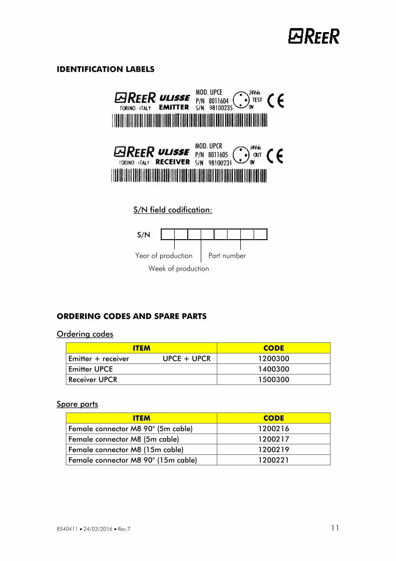
IDENTIFICATION LABELS
ORDERING CODES AND SPARE PARTS
Ordering codes
ITEM CODE
Emitter + receiver UPCE + UPCR 1200300
Emitter UPCE 1400300
Receiver UPCR 1500300
Spare parts
ITEM CODE
Female connector M8 90° (5m cable) 1200216
Female connector M8 (5m cable) 1200217
Female connector M8 (15m cable) 1200219
Female connector M8 90° (15m cable) 1200221
S/N field codification:
S/N
Year of production Part number
Week of production
MOD. UPCE
P/N 8011604
MOD. UPCR
P/N 8011605
12 8540411 24/03/2016 Rev.7
WARRANTY
For each newly produced ULISSE UPC, in regular utilisation conditions, REER S.p.A.
warranties the absence of defects in terms of materials and construction for a period of 12
(twelve) months.
During said period, REER S.p.A. undertakes to eliminate any product law by repairing or
replacing the defective parts, at no cost to the buyer where both the materials and labour
are concerned.
At any rate, REER S.p.A. reserves the right to replace a defective apparatus in its entirety,
with another of identical or similar characteristics, instead of repairing individual defective
parts, at its discretion.
The validity of this warranty is subject to the following conditions:
The fault is notified to REER S.p.A. within twelve months of the date of delivery of the
product.
The parts making up the equipment are undamaged.
The REER part number is clearly legible.
The fault or malfunctioning has not been directly originated by any of the following
causes:
– Utilisation for purposes other than those the equipment is intended for;
– Failure to comply with utilisation instructions;
– Negligence, human errors, inadequate maintenance;
– Repairs, changes, adaptations not performed by REER personnel, tampering, etc.;
– Accidents or impact (even those due to transport or force majeure);
– Other causes independent of REER S.p.A.
Repairs shall be performed at the laboratories of REER S.p.A., where the material must be
delivered or shipped to: transport expenses and the risks of damage or loss of materials
during shipment shall be borne by the user.
Replaced products and components become the property of REER S.p.A.
REER S.p.A. does not recognise any warranties or rights other than those expressly described
above; in no circumstances shall the user be entitled to seek damage for expenses incurred,
down-time or any other events associated with faults of the product or parts thereof.
The data and instructions contained in this manual may change as ULISSE
products are developed. Since a good knowledge of this manual is essential for
correct use and installation, please always refer to the version contained in the
product's packaging case.

Dichiarazione CE di conformità
EC declaration of conformity
Torino, 22/03/2016
REER SpA
via Carcano 32
10153 – Torino
Italy
dichiara che i sensori di sicurezza della serie ULISSE UPC connessi ad una unità di controllo AUS X o
AUS XM oppure ad un controllore di sicurezza MOSAIC (adeguatamente configurato) costituiscono un sistema
Elettrosensibile di Sicurezza (ESPE) con i seguenti livelli di sicurezza: Tipo 2 (secondo la Norma IEC 61496-1:(ed.3); IEC 61496-2:(ed.2))
SILCL 1 (secondo la Norma IEC 62061: (ed.1))
PL c (secondo la Norma ISO 13849-1:2006)
declares that the ULISSE UPC series safety sensors connected to a control unit AUS X or AUS XM or with
a correctly configured MOSAIC safety controller form an Electro-sensitive Protective Equipment (ESPE)
with the following safety levels: Type 2 (according the Standard IEC 61496-1:(ed.3); IEC 61496-2:(ed.2))
SILCL 1 (according the Standard IEC 62061: (ed.1))
PL c (according the Standard ISO 13849-1:2006)
che sono realizzati in conformità alle seguenti Direttive Europee:
and are realized in compliance with the following European Directives:
2006/42/EC "Direttiva Macchine"
"Machine Directive"
2014/30/EU "Direttiva Compatibilità Elettromagnetica"
"Electromagnetic Compatibility Directive"
2014/35/EU "Direttiva Bassa Tensione"
"Low Voltage Directive"
e sono identici all'esemplare esaminato ed approvato con esame di tipo CE da:
and are identical to the specimen examined and approved with a CE - type approval by:
TÜV SÜD Rail GmbH – Ridlerstrasse 65 – D-80339 – Muenchen – Germany
Carlo Pautasso Simone Scaravelli
Direttore Tecnico Amministratore Delegato
Technical Director Managing director
REER S.p.A.
32 via Carcano 10153 Torino Italia
Tel. +39/0112482215 r.a. Fax +39/011859867 Internet: www.reer.it e-mail: [email protected]