The Bouncing Jet: A Newtonian Liquid Rebounding ofi a...
9
Final draft The Bouncing Jet: A Newtonian Liquid Rebounding off a Free Surface Matthew Thrasher, * Sunghwan Jung, † Yee Kwong Pang, ‡ Chih-Piao Chuu, and Harry L. Swinney § Center for Nonlinear Dynamics and Department of Physics, University of Texas at Austin, Austin TX 78712 (Dated: July 11, 2007) We find that a liquid jet can bounce off a bath of the same liquid if the bath is moving horizontally with respect to the jet. Previous observations of jets rebounding off a bath (e.g. Kaye effect) have been reported only for non-Newtonian fluids, while we observe bouncing jets in a variety of Newtonian fluids, including mineral oil poured by hand. A thin layer of air separates the bouncing jet from the bath, and the relative motion replenishes the film of air. Jets with one or two bounces are stable for a range of viscosity, jet flow rate and velocity, and bath velocity. The bouncing phenomenon exhibits hysteresis and multiple steady states. PACS numbers: 47.15.Rq, 47.15.Gf, 47.55.Dz Keywords: I. INTRODUCTION A liquid stream falling onto the free surface of a liquid bath can merge immediately on contact, plunge through the surface and entrain air [1, 2], coil up like a rope [3], float on the surface prior to coalescing [4], float without ever coalescing [5], or break into droplets [6]. We report in this paper observations of a jet of Newtonian liquid bouncing off a horizontally moving surface of a bath of the same liquid. Figure 1 shows a typical bouncing jet viewed from the side. The jet falls to the bath’s surface, is bent upwards, and undergoes a short flight. After re- bounding once more off the surface, the stream merges with the bath. In all figures the liquid bath is moving to the right, and the stream and bath are the same fluid. This paper examines when and how a liquid jet bounces. The issues that arise in studying the bouncing jet (e.g. non-coalescence, lubrication, and entrainment) are ubiq- uitous in fluid processing, such as pouring and mold cast- ing. They also are critical in the design of bearings [7], gas-liquid reactors [8], film coating equipment [9], and metallurgical procedures [6]. Drops of liquid floating and bouncing on the surface of a bath have been studied scientifically for over 125 years [10–13]. On a pond during a light rainfall, splash- ing raindrops throw up smaller drops, and these smaller drops often can be seen to sit on the water surface mo- mentarily. During this time of noncoalescence, a thin layer of air separates each drop from the pond. Nonco- alescence can be prolonged (sometimes indefinitely) by either replenishing the air between the two liquid bod- ies or slowing the loss of the existing air. This can be * Electronic address: [email protected] † Current address: Mathematics Department, MIT ‡ Current address: Hong Kong University of Science and Technol- ogy. § Electronic address: [email protected] achieved with surfactants [14, 15], vibration [4], micro- gravity [16], a velocity difference between the drop and bath [7], evaporation [17], thermo-capillarity [17], or by increasing the viscosity of the surrounding medium [18]. FIG. 1: A liquid jet bounces twice before merging with the bath, which is moving to the right. The jet and bath are silicone oil of the same viscosity. The upper and lower pictures were taken from above and from below the bath surface; the images were not obtained at the same time or the same angle, so small differences exist. The jet’s image can be seen reflected on the surface. Parameters: liquid viscosity μ = 102 mPa s (about 100 times more viscous than water), jet flow rate Q = 0.35 cm 3 /s, falling height H = 5.0 cm, and horizontal velocity of the bath V bath = 15.7 cm/s. The bouncing of a liquid jet has also been observed for a fluid of elongating polymers incident at a glancing angle on a rotating drum [19]. Bouncing also occurs for a jet of shear-thinning liquid falling onto a pool of the same liquid; this is called the Kaye effect [20]. While this effect is visually similar to the bouncing jet phenomenon presented in this paper, the Kaye effect occurs only in non-Newtonian fluids [21] (see discussion in Section VI). Jets of water colliding midair at a glancing angle can also bounce off each other, because during the collision they are separated by a layer of air [5, 22]. However, no systematic study has been conducted of Newtonian jets bouncing off a bath surface. To measure the condi- tions necessary for the bouncing of a Newtonian liquid
Transcript of The Bouncing Jet: A Newtonian Liquid Rebounding ofi a...
Final draft
The Bouncing Jet:A Newtonian Liquid Rebounding off a Free Surface
Matthew Thrasher,∗ Sunghwan Jung,† Yee Kwong Pang,‡ Chih-Piao Chuu, and Harry L. Swinney§Center for Nonlinear Dynamics and Department of Physics,
University of Texas at Austin, Austin TX 78712(Dated: July 11, 2007)
We find that a liquid jet can bounce off a bath of the same liquid if the bath is moving horizontallywith respect to the jet. Previous observations of jets rebounding off a bath (e.g. Kaye effect)have been reported only for non-Newtonian fluids, while we observe bouncing jets in a variety ofNewtonian fluids, including mineral oil poured by hand. A thin layer of air separates the bouncingjet from the bath, and the relative motion replenishes the film of air. Jets with one or two bouncesare stable for a range of viscosity, jet flow rate and velocity, and bath velocity. The bouncingphenomenon exhibits hysteresis and multiple steady states.
PACS numbers: 47.15.Rq, 47.15.Gf, 47.55.DzKeywords:
I. INTRODUCTION
A liquid stream falling onto the free surface of a liquidbath can merge immediately on contact, plunge throughthe surface and entrain air [1, 2], coil up like a rope [3],float on the surface prior to coalescing [4], float withoutever coalescing [5], or break into droplets [6]. We reportin this paper observations of a jet of Newtonian liquidbouncing off a horizontally moving surface of a bath ofthe same liquid. Figure 1 shows a typical bouncing jetviewed from the side. The jet falls to the bath’s surface,is bent upwards, and undergoes a short flight. After re-bounding once more off the surface, the stream mergeswith the bath. In all figures the liquid bath is moving tothe right, and the stream and bath are the same fluid.This paper examines when and how a liquid jet bounces.The issues that arise in studying the bouncing jet (e.g.non-coalescence, lubrication, and entrainment) are ubiq-uitous in fluid processing, such as pouring and mold cast-ing. They also are critical in the design of bearings [7],gas-liquid reactors [8], film coating equipment [9], andmetallurgical procedures [6].
Drops of liquid floating and bouncing on the surfaceof a bath have been studied scientifically for over 125years [10–13]. On a pond during a light rainfall, splash-ing raindrops throw up smaller drops, and these smallerdrops often can be seen to sit on the water surface mo-mentarily. During this time of noncoalescence, a thinlayer of air separates each drop from the pond. Nonco-alescence can be prolonged (sometimes indefinitely) byeither replenishing the air between the two liquid bod-ies or slowing the loss of the existing air. This can be
∗Electronic address: [email protected]†Current address: Mathematics Department, MIT‡Current address: Hong Kong University of Science and Technol-ogy.§Electronic address: [email protected]
achieved with surfactants [14, 15], vibration [4], micro-gravity [16], a velocity difference between the drop andbath [7], evaporation [17], thermo-capillarity [17], or byincreasing the viscosity of the surrounding medium [18].
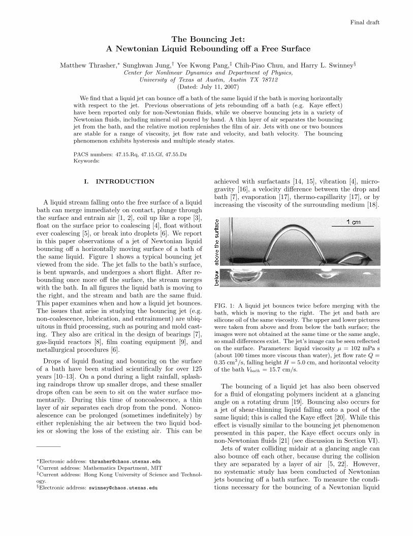
FIG. 1: A liquid jet bounces twice before merging with thebath, which is moving to the right. The jet and bath aresilicone oil of the same viscosity. The upper and lower pictureswere taken from above and from below the bath surface; theimages were not obtained at the same time or the same angle,so small differences exist. The jet’s image can be seen reflectedon the surface. Parameters: liquid viscosity µ = 102 mPa s(about 100 times more viscous than water), jet flow rate Q =0.35 cm3/s, falling height H = 5.0 cm, and horizontal velocityof the bath Vbath = 15.7 cm/s.
The bouncing of a liquid jet has also been observedfor a fluid of elongating polymers incident at a glancingangle on a rotating drum [19]. Bouncing also occurs fora jet of shear-thinning liquid falling onto a pool of thesame liquid; this is called the Kaye effect [20]. While thiseffect is visually similar to the bouncing jet phenomenonpresented in this paper, the Kaye effect occurs only innon-Newtonian fluids [21] (see discussion in Section VI).
Jets of water colliding midair at a glancing angle canalso bounce off each other, because during the collisionthey are separated by a layer of air [5, 22]. However,no systematic study has been conducted of Newtonianjets bouncing off a bath surface. To measure the condi-tions necessary for the bouncing of a Newtonian liquid
2
jet, we built an experimental apparatus (Section II), andwe found that jets bounce for a wide range of parameters(Section III). By comparing the energies associated withthe non-bouncing and bouncing states, we suggest whybouncing is preferred rather than plunging (Section IV).A bouncing jet can easily be reproduced with commonmaterials (Section V). These observations are related toprevious work in Section VI.
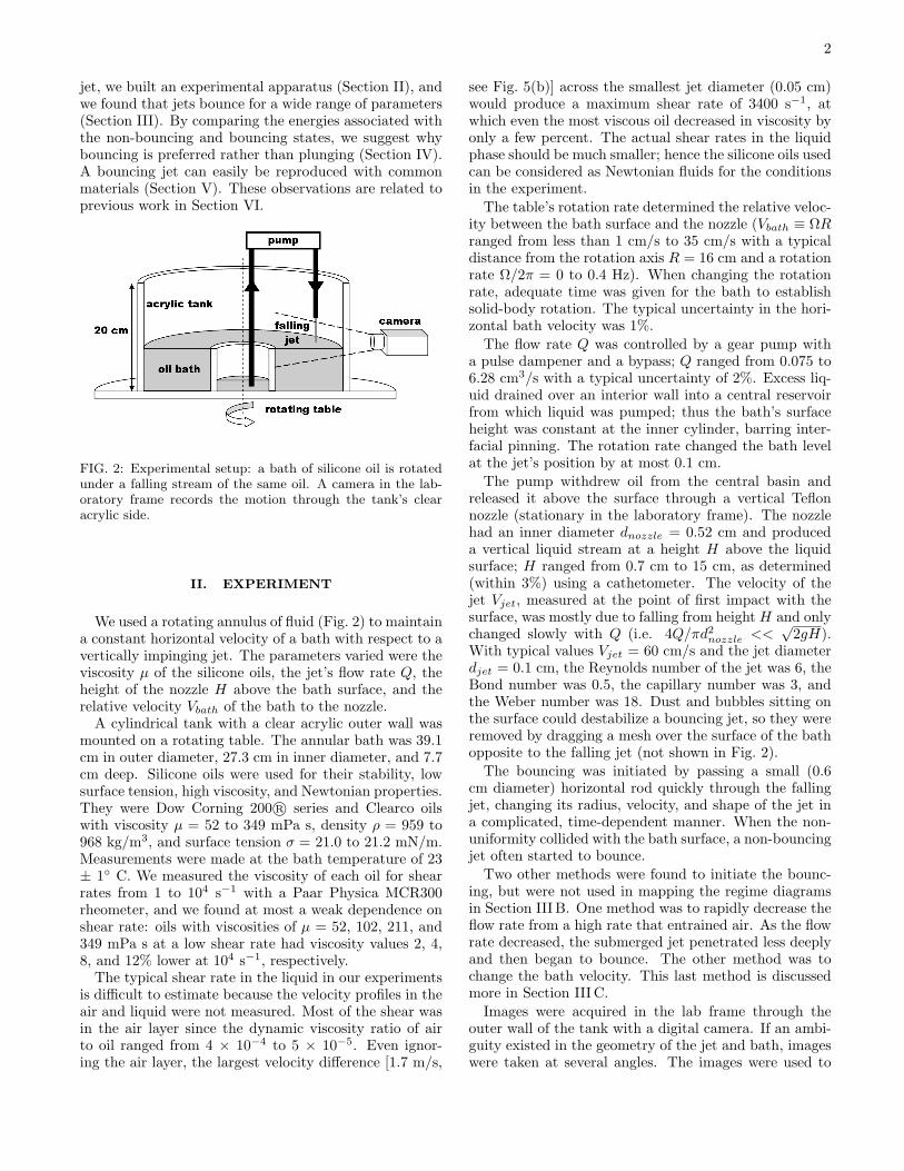
FIG. 2: Experimental setup: a bath of silicone oil is rotatedunder a falling stream of the same oil. A camera in the lab-oratory frame records the motion through the tank’s clearacrylic side.
II. EXPERIMENT
We used a rotating annulus of fluid (Fig. 2) to maintaina constant horizontal velocity of a bath with respect to avertically impinging jet. The parameters varied were theviscosity µ of the silicone oils, the jet’s flow rate Q, theheight of the nozzle H above the bath surface, and therelative velocity Vbath of the bath to the nozzle.
A cylindrical tank with a clear acrylic outer wall wasmounted on a rotating table. The annular bath was 39.1cm in outer diameter, 27.3 cm in inner diameter, and 7.7cm deep. Silicone oils were used for their stability, lowsurface tension, high viscosity, and Newtonian properties.They were Dow Corning 200 R© series and Clearco oilswith viscosity µ = 52 to 349 mPa s, density ρ = 959 to968 kg/m3, and surface tension σ = 21.0 to 21.2 mN/m.Measurements were made at the bath temperature of 23± 1 C. We measured the viscosity of each oil for shearrates from 1 to 104 s−1 with a Paar Physica MCR300rheometer, and we found at most a weak dependence onshear rate: oils with viscosities of µ = 52, 102, 211, and349 mPa s at a low shear rate had viscosity values 2, 4,8, and 12% lower at 104 s−1, respectively.
The typical shear rate in the liquid in our experimentsis difficult to estimate because the velocity profiles in theair and liquid were not measured. Most of the shear wasin the air layer since the dynamic viscosity ratio of airto oil ranged from 4 × 10⁻⁴ to 5 × 10⁻⁵. Even ignor-ing the air layer, the largest velocity difference [1.7 m/s,
see Fig. 5(b)] across the smallest jet diameter (0.05 cm)would produce a maximum shear rate of 3400 s−1, atwhich even the most viscous oil decreased in viscosity byonly a few percent. The actual shear rates in the liquidphase should be much smaller; hence the silicone oils usedcan be considered as Newtonian fluids for the conditionsin the experiment.
The table’s rotation rate determined the relative veloc-ity between the bath surface and the nozzle (Vbath ≡ ΩRranged from less than 1 cm/s to 35 cm/s with a typicaldistance from the rotation axis R = 16 cm and a rotationrate Ω/2π = 0 to 0.4 Hz). When changing the rotationrate, adequate time was given for the bath to establishsolid-body rotation. The typical uncertainty in the hori-zontal bath velocity was 1%.
The flow rate Q was controlled by a gear pump witha pulse dampener and a bypass; Q ranged from 0.075 to6.28 cm3/s with a typical uncertainty of 2%. Excess liq-uid drained over an interior wall into a central reservoirfrom which liquid was pumped; thus the bath’s surfaceheight was constant at the inner cylinder, barring inter-facial pinning. The rotation rate changed the bath levelat the jet’s position by at most 0.1 cm.
The pump withdrew oil from the central basin andreleased it above the surface through a vertical Teflonnozzle (stationary in the laboratory frame). The nozzlehad an inner diameter dnozzle = 0.52 cm and produceda vertical liquid stream at a height H above the liquidsurface; H ranged from 0.7 cm to 15 cm, as determined(within 3%) using a cathetometer. The velocity of thejet Vjet, measured at the point of first impact with thesurface, was mostly due to falling from height H and onlychanged slowly with Q (i.e. 4Q/πd2
nozzle <<√
2gH).With typical values Vjet = 60 cm/s and the jet diameterdjet = 0.1 cm, the Reynolds number of the jet was 6, theBond number was 0.5, the capillary number was 3, andthe Weber number was 18. Dust and bubbles sitting onthe surface could destabilize a bouncing jet, so they wereremoved by dragging a mesh over the surface of the bathopposite to the falling jet (not shown in Fig. 2).
The bouncing was initiated by passing a small (0.6cm diameter) horizontal rod quickly through the fallingjet, changing its radius, velocity, and shape of the jet ina complicated, time-dependent manner. When the non-uniformity collided with the bath surface, a non-bouncingjet often started to bounce.
Two other methods were found to initiate the bounc-ing, but were not used in mapping the regime diagramsin Section III B. One method was to rapidly decrease theflow rate from a high rate that entrained air. As the flowrate decreased, the submerged jet penetrated less deeplyand then began to bounce. The other method was tochange the bath velocity. This last method is discussedmore in Section III C.
Images were acquired in the lab frame through theouter wall of the tank with a digital camera. If an ambi-guity existed in the geometry of the jet and bath, imageswere taken at several angles. The images were used to

3
(a) (b) (c)1 cm
FIG. 3: Photographs (top) and schematic drawings (bottom) of the jet for different horizontal velocities of the bath, Vbath:(a) 0.656 cm/s, a jet bouncing nearly vertically. (b) 3.28 cm/s, a jet bouncing more obliquely. (c) 42.3 cm/s, a trailing(non-bouncing) jet. Increasing Vbath imparts more horizontal momentum to the rebounding jet. The schematics exaggeratethe thickness of the layer of air between the jet and bath. For (a) and (b), the dark horizontal line is the surface’s meniscuson the outer tank wall; in (c), the top and bottom images were taken above and below the surface, so that the surface extendsback in perspective. Parameters in (a) and (b) were µ = 349 mPa s, Q = 0.16 cm3/s, H = 4.2 cm; in (c), µ = 102 mPa s, Q= 0.35 cm3/s, H = 5.0 cm.
measure the diameter of the jet, and the velocity wascomputed by using the flow rate and continuity. Thetypical uncertainty of the vertical velocity measurementwas 8%.
III. RESULTS
A. Dependence on bath velocity and flow rate
Two important parameters that change the qualitativebehavior of the jet are the bath velocity and the flowrate. At low bath velocity, the jet bounced with a nearlyvertical rebound, as in Fig. 3(a). At smaller bath velocity,the jet bounced only intermittently because the bouncingliquid would collide with the falling jet or would distortthe surface and destabilize the bouncing. To get a stablebounce the bath velocity had to be fast enough to carryaway the rebounding fluid so it would not disturb theimpinging jet. The bouncing could stop in another way:the height of the jet’s bounce would quickly decrease untilthe jet merged with the bath.
As the bath velocity increased, the rebound becamemore oblique, as in Fig. 3(b). As a function of the bath’shorizontal velocity, the jet gained more horizontal mo-mentum from the bath and the angle of the jet’s reboundchanged continuously.
During bouncing, the jet and the bath were separatedby a lubricating layer of air, as revealed by a laser beampropagating down the falling jet. The beam was inter-nally reflected within the jet while the jet bounced, andentered the bath only when the jet and bath merged af-terward. We did not measure the thickness of the airlayer, but for a plunging jet the air layer surrounding ajet has been measured by Lorenceau et al. [2] to be sev-eral micrometers thick. For a rebounding water drop,the minimum thickness of the air film was calculated byJayaratne and Mason [23] to be about 0.1 µm. For apendant drop suspended above a moving solid surface,the thickness of the film was measured by Vetrano andDell’Aversana to be a few micrometers on average, andthe shape of the film did not change significantly if theambient pressure of the surrounding air was at least 300to 400 mbar [17].
The velocity of the bath necessary for a stable bouncewas small compared to the jet velocity. Defining the jetincidence angle as θ = tan−1(Vjet/Vbath), we found thatθ only ranged from 83 to 90, while the angle of rebound(in the bath’s frame) ranged from 20 to 80 (for µ = 349mPa s, Q from 0.16 to 0.52 cm3/s, H = 4.2 cm, and Vbath
from 0.7 to 7.9 cm/s). For these conditions, 13 to 29% ofthe jet’s speed was lost while bouncing. Typically, the jetrebounded with higher speed with increasing Vbath untilthe jet rebounded low enough for its increasing contactwith the bath to slow the jet substantially. This trend
4
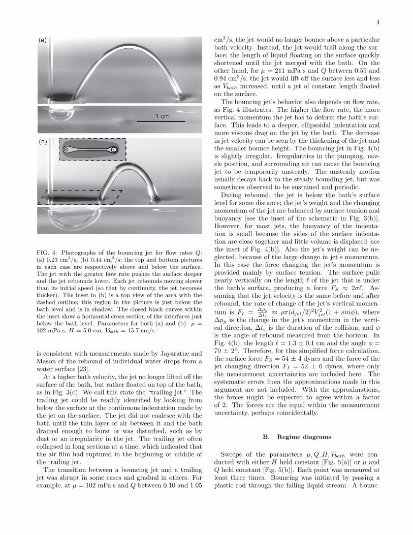
FIG. 4: Photographs of the bouncing jet for flow rates Q:(a) 0.23 cm3/s, (b) 0.44 cm3/s; the top and bottom picturesin each case are respectively above and below the surface.The jet with the greater flow rate pushes the surface deeperand the jet rebounds lower. Each jet rebounds moving slowerthan its initial speed (so that by continuity, the jet becomesthicker). The inset in (b) is a top view of the area with thedashed outline; this region in the picture is just below thebath level and is in shadow. The closed black curves withinthe inset show a horizontal cross section of the interfaces justbelow the bath level. Parameters for both (a) and (b): µ =102 mPa s, H = 5.0 cm, Vbath = 15.7 cm/s.
is consistent with measurements made by Jayaratne andMason of the rebound of individual water drops from awater surface [23].
At a higher bath velocity, the jet no longer lifted off thesurface of the bath, but rather floated on top of the bath,as in Fig. 3(c). We call this state the “trailing jet.” Thetrailing jet could be readily identified by looking frombelow the surface at the continuous indentation made bythe jet on the surface. The jet did not coalesce with thebath until the thin layer of air between it and the bathdrained enough to burst or was disturbed, such as bydust or an irregularity in the jet. The trailing jet oftencollapsed in long sections at a time, which indicated thatthe air film had ruptured in the beginning or middle ofthe trailing jet.
The transition between a bouncing jet and a trailingjet was abrupt in some cases and gradual in others. Forexample, at µ = 102 mPa s and Q between 0.10 and 1.05
cm3/s, the jet would no longer bounce above a particularbath velocity. Instead, the jet would trail along the sur-face; the length of liquid floating on the surface quicklyshortened until the jet merged with the bath. On theother hand, for µ = 211 mPa s and Q between 0.55 and0.94 cm3/s, the jet would lift off the surface less and lessas Vbath increased, until a jet of constant length floatedon the surface.
The bouncing jet’s behavior also depends on flow rate,as Fig. 4 illustrates. The higher the flow rate, the morevertical momentum the jet has to deform the bath’s sur-face. This leads to a deeper, ellipsoidal indentation andmore viscous drag on the jet by the bath. The decreasein jet velocity can be seen by the thickening of the jet andthe smaller bounce height. The bouncing jet in Fig. 4(b)is slightly irregular. Irregularities in the pumping, noz-zle position, and surrounding air can cause the bouncingjet to be temporarily unsteady. The unsteady motionusually decays back to the steady bounding jet, but wassometimes observed to be sustained and periodic.
During rebound, the jet is below the bath’s surfacelevel for some distance; the jet’s weight and the changingmomentum of the jet are balanced by surface tension andbuoyancy [see the inset of the schematic in Fig. 3(b)].However, for most jets, the buoyancy of the indenta-tion is small because the sides of the surface indenta-tion are close together and little volume is displaced [seethe inset of Fig. 4(b)]. Also the jet’s weight can be ne-glected, because of the large change in jet’s momentum.In this case the force changing the jet’s momentum isprovided mainly by surface tension. The surface pullsnearly vertically on the length ` of the jet that is underthe bath’s surface, producing a force FS ≈ 2σ`. As-suming that the jet velocity is the same before and afterrebound, the rate of change of the jet’s vertical momen-tum is FI = ∆py
∆tc≈ ρπ(djet/2)2V 2
jet(1 + sinφ), where∆py is the change in the jet’s momentum in the verti-cal direction, ∆tc is the duration of the collision, and φis the angle of rebound measured from the horizon. InFig. 4(b), the length ` = 1.3 ± 0.1 cm and the angle φ =70 ± 2. Therefore, for this simplified force calculation,the surface force FS = 54 ± 4 dynes and the force of thejet changing direction FI = 52 ± 6 dynes, where onlythe measurement uncertainties are included here. Thesystematic errors from the approximations made in thisargument are not included. With the approximations,the forces might be expected to agree within a factorof 2. The forces are the equal within the measurementuncertainty, perhaps coincidentally.
B. Regime diagrams
Sweeps of the parameters µ,Q,H, Vbath were con-ducted with either H held constant [Fig. 5(a)] or µ andQ held constant [Fig. 5(b)]. Each point was measured atleast three times. Bouncing was initiated by passing aplastic rod through the falling liquid stream. A bounc-
5
ing stream was considered “initiated” after 5 s; most jetsthat were stable for 5 s would persist for much longertimes. The initiation procedure yielded transition pa-rameter values that were reproducible and consistent fordifferent experimenters. The choice of 5 s persistence foridentifying a stable bounce is arbitrary; a criterion of 1 sduration would yield parameter space regions for bounc-ing somewhat larger than those in Fig. 5.
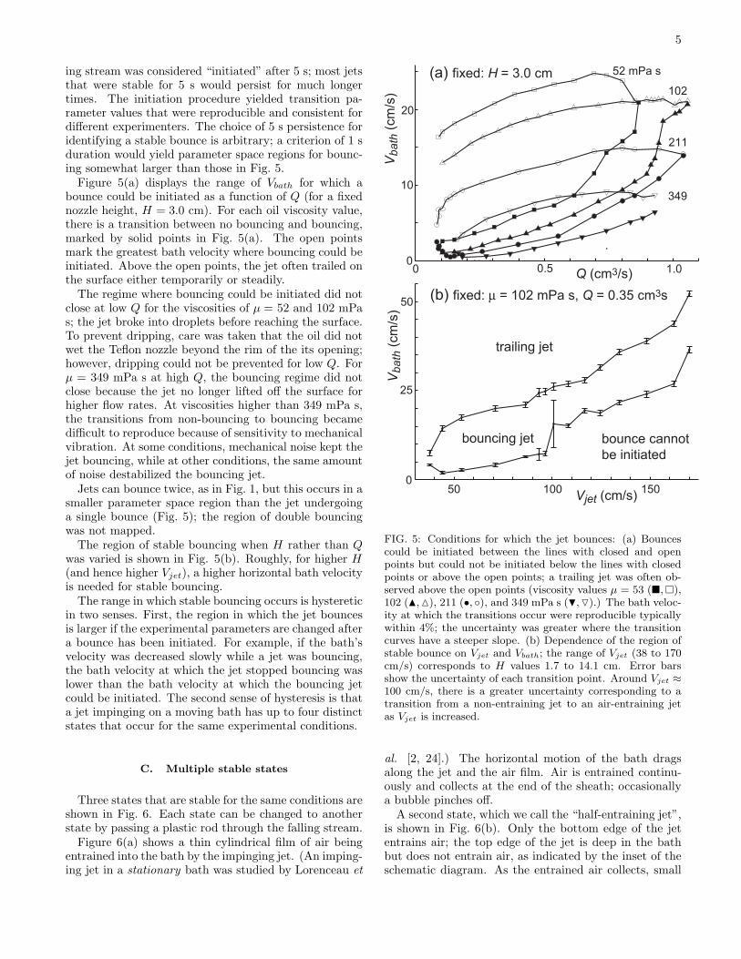
Figure 5(a) displays the range of Vbath for which abounce could be initiated as a function of Q (for a fixednozzle height, H = 3.0 cm). For each oil viscosity value,there is a transition between no bouncing and bouncing,marked by solid points in Fig. 5(a). The open pointsmark the greatest bath velocity where bouncing could beinitiated. Above the open points, the jet often trailed onthe surface either temporarily or steadily.
The regime where bouncing could be initiated did notclose at low Q for the viscosities of µ = 52 and 102 mPas; the jet broke into droplets before reaching the surface.To prevent dripping, care was taken that the oil did notwet the Teflon nozzle beyond the rim of the its opening;however, dripping could not be prevented for low Q. Forµ = 349 mPa s at high Q, the bouncing regime did notclose because the jet no longer lifted off the surface forhigher flow rates. At viscosities higher than 349 mPa s,the transitions from non-bouncing to bouncing becamedifficult to reproduce because of sensitivity to mechanicalvibration. At some conditions, mechanical noise kept thejet bouncing, while at other conditions, the same amountof noise destabilized the bouncing jet.
Jets can bounce twice, as in Fig. 1, but this occurs in asmaller parameter space region than the jet undergoinga single bounce (Fig. 5); the region of double bouncingwas not mapped.
The region of stable bouncing when H rather than Qwas varied is shown in Fig. 5(b). Roughly, for higher H(and hence higher Vjet), a higher horizontal bath velocityis needed for stable bouncing.
The range in which stable bouncing occurs is hystereticin two senses. First, the region in which the jet bouncesis larger if the experimental parameters are changed aftera bounce has been initiated. For example, if the bath’svelocity was decreased slowly while a jet was bouncing,the bath velocity at which the jet stopped bouncing waslower than the bath velocity at which the bouncing jetcould be initiated. The second sense of hysteresis is thata jet impinging on a moving bath has up to four distinctstates that occur for the same experimental conditions.
C. Multiple stable states
Three states that are stable for the same conditions areshown in Fig. 6. Each state can be changed to anotherstate by passing a plastic rod through the falling stream.
Figure 6(a) shows a thin cylindrical film of air beingentrained into the bath by the impinging jet. (An imping-ing jet in a stationary bath was studied by Lorenceau et
0 0.5 1.00
10
20
50 100 1500
25
50
Vb
ath
(cm
/s)
Q (cm3/s)
Vjet (cm/s)
Vb
ath
(cm
/s)
trailing jet
bouncing jet bounce cannot
be initiated
52 mPa s
211
349
102
(a) fixed: H = 3.0 cm
(b) fixed: µ = 102 mPa s, Q = 0.35 cm3s
FIG. 5: Conditions for which the jet bounces: (a) Bouncescould be initiated between the lines with closed and openpoints but could not be initiated below the lines with closedpoints or above the open points; a trailing jet was often ob-served above the open points (viscosity values µ = 53 (¥, ¤),102 (N, M), 211 (•, ), and 349 mPa s (H, O).) The bath veloc-ity at which the transitions occur were reproducible typicallywithin 4%; the uncertainty was greater where the transitioncurves have a steeper slope. (b) Dependence of the region ofstable bounce on Vjet and Vbath; the range of Vjet (38 to 170cm/s) corresponds to H values 1.7 to 14.1 cm. Error barsshow the uncertainty of each transition point. Around Vjet ≈100 cm/s, there is a greater uncertainty corresponding to atransition from a non-entraining jet to an air-entraining jetas Vjet is increased.
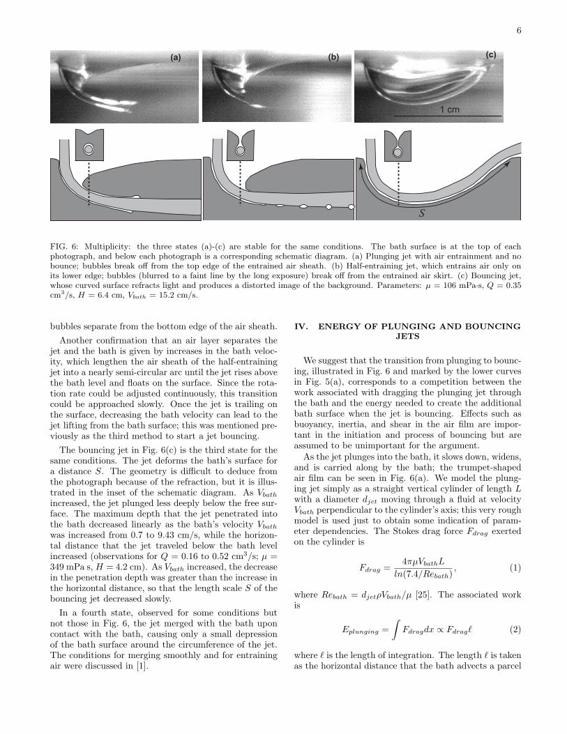
al. [2, 24].) The horizontal motion of the bath dragsalong the jet and the air film. Air is entrained continu-ously and collects at the end of the sheath; occasionallya bubble pinches off.
A second state, which we call the “half-entraining jet”,is shown in Fig. 6(b). Only the bottom edge of the jetentrains air; the top edge of the jet is deep in the bathbut does not entrain air, as indicated by the inset of theschematic diagram. As the entrained air collects, small
6
S
1 cm
(a) (b) (c)
FIG. 6: Multiplicity: the three states (a)-(c) are stable for the same conditions. The bath surface is at the top of eachphotograph, and below each photograph is a corresponding schematic diagram. (a) Plunging jet with air entrainment and nobounce; bubbles break off from the top edge of the entrained air sheath. (b) Half-entraining jet, which entrains air only onits lower edge; bubbles (blurred to a faint line by the long exposure) break off from the entrained air skirt. (c) Bouncing jet,whose curved surface refracts light and produces a distorted image of the background. Parameters: µ = 106 mPa·s, Q = 0.35cm3/s, H = 6.4 cm, Vbath = 15.2 cm/s.
bubbles separate from the bottom edge of the air sheath.Another confirmation that an air layer separates the
jet and the bath is given by increases in the bath veloc-ity, which lengthen the air sheath of the half-entrainingjet into a nearly semi-circular arc until the jet rises abovethe bath level and floats on the surface. Since the rota-tion rate could be adjusted continuously, this transitioncould be approached slowly. Once the jet is trailing onthe surface, decreasing the bath velocity can lead to thejet lifting from the bath surface; this was mentioned pre-viously as the third method to start a jet bouncing.
The bouncing jet in Fig. 6(c) is the third state for thesame conditions. The jet deforms the bath’s surface fora distance S. The geometry is difficult to deduce fromthe photograph because of the refraction, but it is illus-trated in the inset of the schematic diagram. As Vbath
increased, the jet plunged less deeply below the free sur-face. The maximum depth that the jet penetrated intothe bath decreased linearly as the bath’s velocity Vbath
was increased from 0.7 to 9.43 cm/s, while the horizon-tal distance that the jet traveled below the bath levelincreased (observations for Q = 0.16 to 0.52 cm3/s; µ =349 mPa s, H = 4.2 cm). As Vbath increased, the decreasein the penetration depth was greater than the increase inthe horizontal distance, so that the length scale S of thebouncing jet decreased slowly.
In a fourth state, observed for some conditions butnot those in Fig. 6, the jet merged with the bath uponcontact with the bath, causing only a small depressionof the bath surface around the circumference of the jet.The conditions for merging smoothly and for entrainingair were discussed in [1].
IV. ENERGY OF PLUNGING AND BOUNCINGJETS
We suggest that the transition from plunging to bounc-ing, illustrated in Fig. 6 and marked by the lower curvesin Fig. 5(a), corresponds to a competition between thework associated with dragging the plunging jet throughthe bath and the energy needed to create the additionalbath surface when the jet is bouncing. Effects such asbuoyancy, inertia, and shear in the air film are impor-tant in the initiation and process of bouncing but areassumed to be unimportant for the argument.
As the jet plunges into the bath, it slows down, widens,and is carried along by the bath; the trumpet-shapedair film can be seen in Fig. 6(a). We model the plung-ing jet simply as a straight vertical cylinder of length Lwith a diameter djet moving through a fluid at velocityVbath perpendicular to the cylinder’s axis; this very roughmodel is used just to obtain some indication of param-eter dependencies. The Stokes drag force Fdrag exertedon the cylinder is
Fdrag =4πµVbathL
ln(7.4/Rebath), (1)
where Rebath = djetρVbath/µ [25]. The associated workis
Eplunging =∫
Fdragdx ∝ Fdrag` (2)
where ` is the length of integration. The length ` is takenas the horizontal distance that the bath advects a parcel
7
of the jet during the time ∆t that it traverses the cylinderof length L traveling with velocity Vjet,
` = Vbath∆t = VbathL
Vjet. (3)
The length of the cylinder L is expected to increasewith Q and Vjet, and decrease with µ and Vbath. In accordwith the expected functional dependence of the cylinderlength, we take as an ansatz
L ∼ a
√Q
Vbath, (4)
where a = 20 (dimensionless) makes L comparable to es-timates of the effective jet length, which is longer thanthe air sheath (typically 0.5-2 cm) since the jet pene-trates farther than the air sheath. With this factor athe energies Eplunging and Ebouncing are comparable, butgiven the neglected coefficients and many rough approx-imations of our model, the energy magnitudes are veryuncertain.
Substituting ` and L into the expression for the energyof plunging yields
Eplunging ∼ 4πµVbatha2Q
Vjetln(7.4/Rebath). (5)
Because most of the jet’s velocity is due to gravity andthe data are taken at the same height H, we assume Vjet
is constant.Now consider the energy associated with the additional
surface needed to separate the rebounding jet from thebath. The energy of the new interfacial surface scales asan area
Ebouncing =∫
σdA ∼ σS2 , (6)
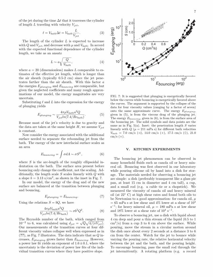
where S is the arc-length of the roughly ellipsoidal in-dentation on the bath. The surface area present beforebouncing only change the coefficient, not the scaling. Ad-ditionally, the length scale S scales linearly with Q witha slope b = 3.13 s/cm2, as shown in the inset in Fig. 7.
In our model, the energy of the drag and of the newsurface are balanced at the transition between plungingand bouncing,
Eplunging = Ebouncing. (7)
Using the relations S = bQ, we have
4πµVbatha2Q
Vjetln(7.4/Rebath)∼ σb2Q2. (8)
The Reynolds number of the bath, which ranged from10−2 to 6, was calculated using djet =
√Q
√4/(πVjet).
Our measurements of the transition curves at four dif-ferent viscosity values collapse well when expressed as in(??), as Fig. 7 illustrates. The data indicate that as Q in-creases, Eplunging grows faster than Ebouncing. However,a power law fit yields an exponent of 1.6±0.1, where theuncertainty is the deviation of power law fits of the indi-vidual transition curves where they have positive slope.
100
101
102
101
102
103
Ebouncing (erg)
Eplu
ngin
g (
erg
)
0 0.2 0.4 0.60
1.0
2.0
Q (cm3/s)
S (
cm
)
FIG. 7: It is suggested that plunging is energetically favoredbelow the curves while bouncing is energetically favored abovethe curves. The argument is supported by the collapse of thedata for four viscosity values (ranging by a factor of seven)onto the same approximate curve. The energy Eplunging,given in (5), is from the viscous drag of the plunging jet.The energy Ebouncing, given in (6), is from the surface area ofthe bouncing jet. The solid symbols and data points are thesame as in Fig. 5(a). Inset: the penetration length S varieslinearly with Q (µ = 211 mPa s) for different bath velocitiesVbath = 7.0 cm/s (C), 14.0 cm/s (+), 17.5 cm/s (♦), 21.0cm/s (×).
V. KITCHEN EXPERIMENTS
The bouncing jet phenomenon can be observed inmany household fluids such as canola oil or heavy min-eral oil. Bouncing was first observed in our laboratorywhile pouring silicone oil by hand into a dish for stor-age. The materials needed for observing a bouncing jetare simple: a dish (preferably transparent like a glass piepan, at least 15 cm in diameter and 4 cm tall), a cup,and a small rod (e.g. a cable tie or a chopstick). Wemeasured the viscosity of canola oil and heavy mineraloil (at 22 C) at high shear rates and found both oils tobe Newtonian to a good approximation: for canola oil, µ= 65 mPa s at low shear and 4% lower at a shear of 104
s−1; for heavy mineral oil, µ = 180 mPa s at low shearand 18% lower at a shear rate of 104 s−1.
To observe a bouncing jet, use a dish with liquid about4 cm deep and pour a thin stream of the liquid (0.5 to 1cm3/s) from a cup 3 to 6 cm above the surface. Whilepouring, move the stream in a circular motion aroundthe dish once about every 2 seconds at a distance 3 to 6cm from the center. Watch for the jet to bounce whilevarying the pouring rate, the relative horizontal velocitybetween the jet and the bath, and the pouring height.To encourage bouncing, pass the small rod through thejet intermittently. A rotating platform (e.g. a record
8
turntable or a Lazy Susan) can be used to rotate the dishinstead of moving the cup. If the surface is dirty, cleanthe surface by stirring the bath or scraping the surface[11, 22]. Blow air on the surface to pop bubbles on thesurface. To achieve a very small pouring height, pour theliquid down the rod.
With practice, a jet poured by hand can bounce sta-bly for tens of seconds at a time. For more detailed in-structions and for more liquids and conditions, see [26].Bouncing is also easy to observe in non-Newtonian fluidssuch shampoo, multigrade motor oil, and concentratedmixtures of liquid soap and water, but the mechanismby which they bounce may not be the same as for New-tonian fluids.
VI. DISCUSSION
We have observed a falling jet of a Newtonian liquidbouncing from a moving bath of the same liquid for awide range of viscosity (52 to 349 mPa s), jet diameter(0.05 to 0.12 cm), jet velocity at impact (38 to 170 cm/s),and the bath’s horizontal velocity (0.5 to 35 cm/s). Byinitiating the jet in different ways, as many as four sta-ble states were observed for the same experimental con-ditions.
The bouncing jet is a new example of steady non-coalescence and a new example of a fluid flow with mul-tiple stable states. Bouncing jets could be used as a newtechnique for controlling a fluid jet and preventing or pro-moting the entrainment of the fluid surrounding the jet.The phenomenon can be observed easily with a varietyof fluids at home.
The bouncing phenomenon we have studied is simi-lar to the Kaye effect: both are thin streams of liquidrebounding from a surface, and both occur for similarfalling heights, jet velocities, and jet diameters. However,
the liquid of the stable Kaye effect is non-Newtonian,while we have studied bouncing for Newtownian liquids.The Newtonian bouncing liquid jet is separated from thebath by an air layer, likely 0.1 to 10 µm thick (see dis-cussion in Section IIIA) [2, 17, 23]. In contrast, thestable Kaye effect is lubricated by a shear-thinned layerof liquid about 100 µm thick [21]. The bouncing jet alsooccurs for less viscous liquids than the Kaye effect.
The behavior of a bouncing jet is determined by aninterplay of viscous, inertial, surface, and gravitationalforces. This causes the relationship between any two fea-tures of the bouncing jet to be very complicated. We havesuggested that the onset of bouncing can be approachedby comparing the energies of drag on the plunging jet andthe energy of the new surface of the bouncing jet. Whilethe argument collapses the transition curves, it cannotexplain the slope of the curves or their closure at small Q.To understand this transition better, future experimentsshould examine the dependence on other parameters, in-cluding surface tension, density difference, radius of thenozzle, angle of incidence of the jet, and the viscosity andpressure of the surrounding fluid (which was air at atmo-spheric pressure in our experiments). Many of these con-ditions have already been studied for the case of dropletnon-coalescence [5]. In addition, we have observed thata falling jet impinging on a moving bath exhibits otherphenomena that warrant future study [26].
Acknowledgments
We thank W.D. McCormick and J.W.M. Bush for help-ful discussions. We also thank Olivier Praud and AbeYarbrough for help with preliminary experiments. Ac-knowledgment is made to the Donors of the AmericanChemical Society Petroleum Research Fund for supportof this research.
[1] J. Eggers, Phys. Rev. Lett. 86, 4290 (2001).[2] E. Lorenceau, D. Quere, and J. Eggers, Phys. Rev. Lett.
93, 254501 (2004).[3] M. Maleki, M. Habibi, R. Golestanian, N. Ribe, and
D. Bonn, Phys. Rev. Lett. 93, 214502 (2004).[4] Y. Couder, E. Fort, C.-H. Gautier, and A. Boudaoud,
Phys. Rev. Lett. 94, 177801 (2005).[5] G. P. Neitzel and P. Dell’Aversana, Annu. Rev. Fluid
Mech. 34, 267 (2002).[6] K.-Y. Lee, H.-G. Lee, and P. C. Hayes, ISIJ Int. 38, 1233
(1998).[7] P. Dell’Aversana, V. Tontodonato, and L. Carotenuto,
Phys. Fluids 9, 2475 (1997).[8] A. K. Bin, Chem. Eng. Sci. 48, 3585 (1993).[9] P. G. Simpkins and V. J. Kuck, J. Colloid Interface Sci.
263, 562 (2003).[10] Lord Rayleigh, Proc. R. Soc. London 28 (1878-1879).[11] O. Reynolds, Proc. Manchester Lit. Philos. Soc. 21
(1881-82).
[12] J. Walker, Sci. Am. 238, 151 (1978).[13] A. L. Yarin, Annu. Rev. Fluid Mech. 38, 159 (2006).[14] Y. Amarouchene, G. Cristobal, and H. Kellay, Phys. Rev.
Lett. 87, 206104 (2001).[15] N. Vandewalle, D. Terwagne, K. Mulleners, T. Gilet, and
S. Dorbolo, Phys. Fluids 18, 091106 (2006).[16] G. P. Neitzel, P. Dell’Aversana, and D. Castagnolo, in
The Fourth Microgravity Fluid Physics and TransportPhenomena Conference (NASA Lewis Research Center,Cleveland, OH, 1999), Document ID: 20010004358.
[17] M. R. Vetrano and P. Dell’Aversana, Experiments on Air-Lubricated Liquids: Role of Vapor, Electrostatic Effects,and Heat Transmission across the Interface, vol. 628 ofLecture Notes in Physics (Springer Berlin, Heidelberg,2003), online-only supplement.
[18] L. Mahajan, Philos. Mag. 10, 383 (1930).[19] J. Ferguson, N. E. Hudson, and B. C. H. Warren, J. Non-
Newtonian Fluid Mech. 23, 49 (1987).[20] A. Kaye, Nature (London) 197, 1001 (1963).
9
[21] M. Versluis, C. B., D. van der Meer, K. van der Weele,and D. Lohse, J. Stat. Mech. 2006, P07007 (2006).
[22] Lord Rayleigh, Philos. Mag. 48, 321 (1899).[23] O. Jayaratne and B. Mason, Proc. R. Soc. A 280, 545
(1964).[24] E. Lorenceau, F. Restagno, and D. Quere, Phys. Rev.
Lett. 90, 184501 (2003).
[25] H. Lamb, Hydrodynamics (Cambridge University Press,1932), 6th ed.
[26] M. Thrasher, Master’s Thesis: A Liquid Stream Bounc-ing off a Moving Liquid Bath (University of Texas atAustin, 2005).