Rubinstein,Eden HeavyLiftingRocket
13
-
Upload
eden-rubinstein -
Category
Documents
-
view
153 -
download
2
Transcript of Rubinstein,Eden HeavyLiftingRocket
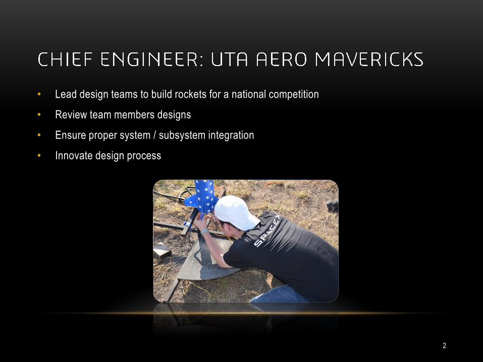
• Lead design teams to build rockets for a national competition
• Review team members designs
• Ensure proper system / subsystem integration
• Innovate design process
2
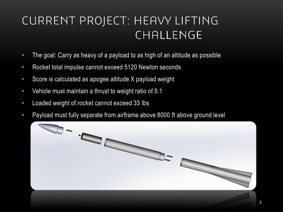
• The goal: Carry as heavy of a payload to as high of an altitude as possible
• Rocket total impulse cannot exceed 5120 Newton seconds
• Score is calculated as apogee altitude X payload weight
• Vehicle must maintain a thrust to weight ratio of 5:1
• Loaded weight of rocket cannot exceed 33 lbs
• Payload must fully separate from airframe above 8000 ft above ground level
3
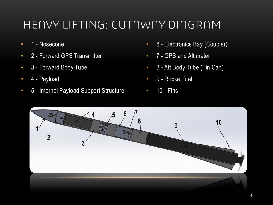
• 1 - Nosecone
• 2 - Forward GPS Transmitter
• 3 - Forward Body Tube
• 4 - Payload
• 5 - Internal Payload Support Structure
• 6 - Electronics Bay (Coupler)
• 7 - GPS and Altimeter
• 8 - Aft Body Tube (Fin Can)
• 9 - Rocket fuel
• 10 - Fins
1
2
9
3
8
4
5
10
6
7
4
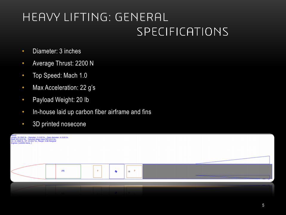
• Diameter: 3 inches
• Average Thrust: 2200 N
• Top Speed: Mach 1.0
• Max Acceleration: 22 g’s
• Payload Weight: 20 lb
• In-house laid up carbon fiber airframe and fins
• 3D printed nosecone
5
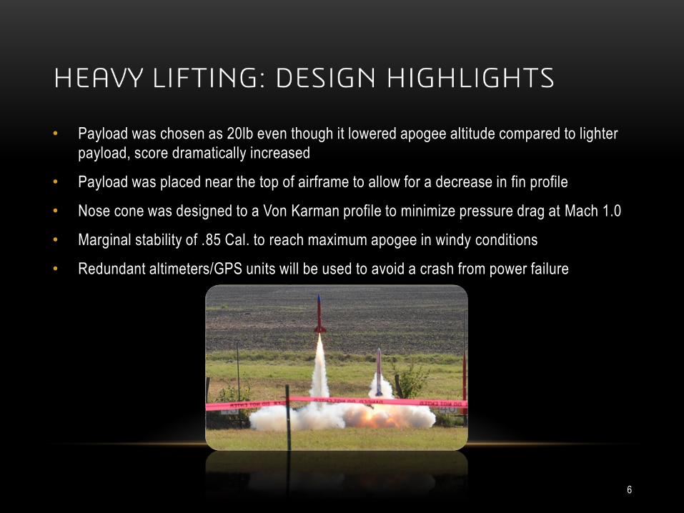
• Payload was chosen as 20lb even though it lowered apogee altitude compared to lighter
payload, score dramatically increased
• Payload was placed near the top of airframe to allow for a decrease in fin profile
• Nose cone was designed to a Von Karman profile to minimize pressure drag at Mach 1.0
• Marginal stability of .85 Cal. to reach maximum apogee in windy conditions
• Redundant altimeters/GPS units will be used to avoid a crash from power failure
6
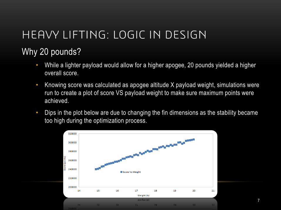
Why 20 pounds?
• While a lighter payload would allow for a higher apogee, 20 pounds yielded a higher
overall score.
• Knowing score was calculated as apogee altitude X payload weight, simulations were
run to create a plot of score VS payload weight to make sure maximum points were
achieved.
• Dips in the plot below are due to changing the fin dimensions as the stability became
too high during the optimization process.
7
Why was the forward end chosen for the payload location?
• By placing the large payload weight in the forward end of the rocket, the stability of
the rocket became very high.
• To compensate for this over-stability, smaller fins could be used. In other words,
since the center of gravity (Cg) was so far forward, the center of pressure (Cp) could
also be moved much closer to the forward end of the vehicle.
• Smaller fins mean a smaller cross sectional area, less skin drag, and consequently a
higher maximum altitude.
8
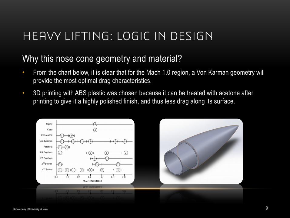
Why this nose cone geometry and material?
• From the chart below, it is clear that for the Mach 1.0 region, a Von Karman geometry will
provide the most optimal drag characteristics.
• 3D printing with ABS plastic was chosen because it can be treated with acetone after
printing to give it a highly polished finish, and thus less drag along its surface.
Plot courtesy of University of Iowa 9
Why a stability of 0.85?
• According to a 100 year weather history of the launch site, average ground level wind
speeds can reach 8-14 mph for launch day.
• It is known that rocket with stability of approximately 1.0 Cal. will face into the wind
during ascent.
• Past rocket design projects show that a stability ratio of 0.8 Cal. will result in a more
vertical flight than a stability ratio of 1.0 Cal.
• Designing the rocket to a stability ratio of 0.85 Cal. will account for added weight to
the fin can during manufacturing due to adhesives and retention hardware, slightly
lowering the stability ratio.
• Stability ratio was calculated by dividing the distance between the Cg and Cp by the
diameter of the rocket.
10
Why 3 flight computers?
• The nose cone and the body tube will each have their own GPS telemetry units. The body tube GPS will not be able to send a signal through the carbon fiber to the ground station until main parachute deployment. During flight, the GPS unit inside the 3D printed nose cone will relay tracking data.
• The GPS unit inside the body tube will be backed up with a separate altimeter system with its own power source, which will be able to activate two ejection charges.
• At apogee, the body tube GPS will fire an ejection charge to separate the fin can. The altimeter will fire another charge one second later as a backup.
• At this point, each GPS will be transmitting data to the ground station
• At 10,000 feet, the body tube GPS and altimeter will fire in the same order as apogee. This will separate the nose cone, payload, and their parachute from the body tube, fin can and their parachute.
11
Rapid gas expansion from large ejection charges to push out a 20 pound payload could cause
damage to airframe.
• Solution: Rocket will have a dual deployment recovery system. The rocket main
parachute will deploy at apogee, forcing the upper section containing the payload to
point down.
• At 10,000 ft above ground level two smaller charges will blow sequentially using a
gravity assist to eject payload with its own parachute and GPS telemetry unit.
12
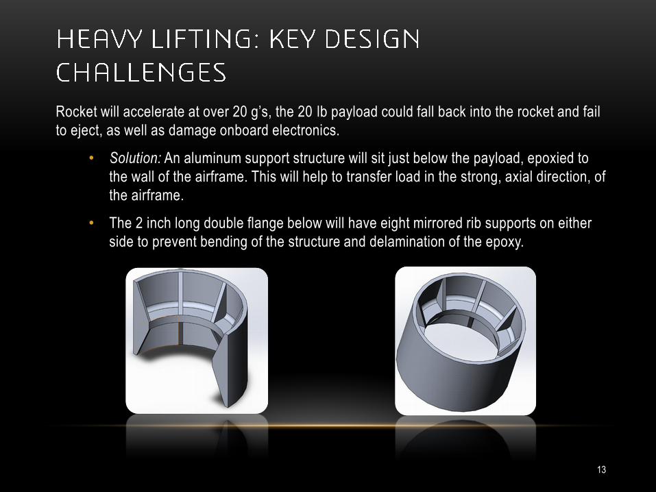
Rocket will accelerate at over 20 g’s, the 20 lb payload could fall back into the rocket and fail
to eject, as well as damage onboard electronics.
• Solution: An aluminum support structure will sit just below the payload, epoxied to
the wall of the airframe. This will help to transfer load in the strong, axial direction, of
the airframe.
• The 2 inch long double flange below will have eight mirrored rib supports on either
side to prevent bending of the structure and delamination of the epoxy.
13