Research Article Design of Wide-Band Bandpass Filter Using ...
6
Research Article Design of Wide-Band Bandpass Filter Using Composite Right/Left-Handed Transmission Line Structure Baoping Ren, 1,2 Haiwen Liu, 1 Xuehui Guan, 1 Pin Wen, 1 Xiang Xiao, 1 and Zhewang Ma 2 1 School of Information Engineering, East China Jiaotong University, Nanchang 330013, China 2 Graduate School of Science and Engineering, Saitama University, Saitama 338-8570, Japan Correspondence should be addressed to Baoping Ren; [email protected] Received 27 November 2015; Revised 19 March 2016; Accepted 29 March 2016 Academic Editor: Jiun-Wei Horng Copyright © 2016 Baoping Ren et al. is is an open access article distributed under the Creative Commons Attribution License, which permits unrestricted use, distribution, and reproduction in any medium, provided the original work is properly cited. A wide-band microstrip bandpass filter (BPF) based on the improved composite right/leſt-handed transmission line (CRLH-TL) structure is presented in this paper. Compared to the traditional CRLH-TL with via hole, the improved one is an all-planar structure, which owns the advantage of fabrication and loss. e equivalent lossless LC circuit model of the proposed structure is established. EM soſtware Sonnet is adopted to design the wide-band filter with bandwidth of 1.4 GHz (from 1.9 GHz to 3.3 GHz). e circuit occupies only 20.6 × 12.8 mm 2 . Finally, the fabrication and measurement are implemented. A good agreement between simulation and measured results verifies the validity of the design methodology. 1. Introduction In recent years, leſt-handed materials (LHMs) have received substantial attention in the scientific and engineering com- munities for their specific electromagnetic (EM) property (simultaneously negative permittivity and permeability ) [1]. Science magazine named LHMs as one of the top ten scientific breakthroughs of 2003 [2]. e first artificial LHM composed of thin copper wires and copper split-ring res- onators (SRRs) was realized by Smith group at the University of California [3]. However, this kind of structure is always difficult to implement for microwave applications because resonant units such as SRRs are lossy and narrow-banded [4]. Several researchers soon realized that transmission lines (TLs) approach towards LHMs was possible [5, 6]. In actual implementation, LHMs are considered to be a more general model of composite right/leſt-handed (CRLH) TLs, which also include right-handed (RH) effects that occur naturally in LH TLs. With CRLH structure, many new kinds of microwave devices are designed for low loss and broadband characteristics, such as divider, phase shiſter, coupler, and leaky-wave antenna [7]. New ultra-wide-band radar and high-rate communica- tion systems require very specialized RF devices capable of operating over wide frequency scope [8]. us, as the key element in RF system, high efficient wide-band bandpass filter (BPF) is no exception in this background. e popular way of designing wide-band filters is employing multiple- mode resonators [9, 10] or signal-interference concepts [11, 12]. However, the circuit sizes of the aforementioned are comparatively large. More recently, CRLH TL unit cells are applied to design compact wide-band filter [13, 14]. Neverthe- less, a via hole or dual-layer structure is indispensable, which complexes the fabrication process. In our previous works, an all-planar CRLH resonator is proposed and fabricated on high-temperature superconducting film [15], which obtains a high performance filtering response with ultralow insertion loss, but the bandwidth is small. In this paper, an improved CRLH TL is proposed to design a wide-band BPF. Patch capacitance replaces tradi- tional via hole connected to shunt inductance in this new structure cell, which reduces the fabrication difficulty and circuit loss. e filter is simulated and optimized by EM soſtware Sonnet and the obtained circuit size is 0.3 × 0.18 ( is the guided wavelength of the 50 Ω line at the center frequency). To observe the LH property, the dispersion diagram is given and researched in the paper. Simulation Hindawi Publishing Corporation Active and Passive Electronic Components Volume 2016, Article ID 6532010, 5 pages http://dx.doi.org/10.1155/2016/6532010
Transcript of Research Article Design of Wide-Band Bandpass Filter Using ...

Research ArticleDesign of Wide-Band Bandpass Filter Using CompositeRight/Left-Handed Transmission Line Structure
Baoping Ren,1,2 Haiwen Liu,1 Xuehui Guan,1 Pin Wen,1 Xiang Xiao,1 and Zhewang Ma2
1School of Information Engineering, East China Jiaotong University, Nanchang 330013, China2Graduate School of Science and Engineering, Saitama University, Saitama 338-8570, Japan
Correspondence should be addressed to Baoping Ren; [email protected]
Received 27 November 2015; Revised 19 March 2016; Accepted 29 March 2016
Academic Editor: Jiun-Wei Horng
Copyright © 2016 Baoping Ren et al. This is an open access article distributed under the Creative Commons Attribution License,which permits unrestricted use, distribution, and reproduction in any medium, provided the original work is properly cited.
A wide-band microstrip bandpass filter (BPF) based on the improved composite right/left-handed transmission line (CRLH-TL)structure is presented in this paper. Compared to the traditional CRLH-TLwith via hole, the improved one is an all-planar structure,which owns the advantage of fabrication and loss.The equivalent lossless LC circuit model of the proposed structure is established.EM software Sonnet is adopted to design the wide-band filter with bandwidth of 1.4 GHz (from 1.9GHz to 3.3 GHz). The circuitoccupies only 20.6 × 12.8mm2. Finally, the fabrication and measurement are implemented. A good agreement between simulationand measured results verifies the validity of the design methodology.
1. Introduction
In recent years, left-handed materials (LHMs) have receivedsubstantial attention in the scientific and engineering com-munities for their specific electromagnetic (EM) property(simultaneously negative permittivity 𝜀 and permeability 𝜇)[1]. Science magazine named LHMs as one of the top tenscientific breakthroughs of 2003 [2]. The first artificial LHMcomposed of thin copper wires and copper split-ring res-onators (SRRs) was realized by Smith group at the Universityof California [3]. However, this kind of structure is alwaysdifficult to implement for microwave applications becauseresonant units such as SRRs are lossy and narrow-banded[4]. Several researchers soon realized that transmission lines(TLs) approach towards LHMs was possible [5, 6]. In actualimplementation, LHMs are considered to be a more generalmodel of composite right/left-handed (CRLH) TLs, whichalso include right-handed (RH) effects that occur naturallyin LH TLs. With CRLH structure, many new kinds ofmicrowave devices are designed for low loss and broadbandcharacteristics, such as divider, phase shifter, coupler, andleaky-wave antenna [7].
New ultra-wide-band radar and high-rate communica-tion systems require very specialized RF devices capable of
operating over wide frequency scope [8]. Thus, as the keyelement in RF system, high efficient wide-band bandpassfilter (BPF) is no exception in this background. The popularway of designing wide-band filters is employing multiple-mode resonators [9, 10] or signal-interference concepts [11,12]. However, the circuit sizes of the aforementioned arecomparatively large. More recently, CRLH TL unit cells areapplied to design compact wide-band filter [13, 14]. Neverthe-less, a via hole or dual-layer structure is indispensable, whichcomplexes the fabrication process. In our previous works,an all-planar CRLH resonator is proposed and fabricated onhigh-temperature superconducting film [15], which obtains ahigh performance filtering response with ultralow insertionloss, but the bandwidth is small.
In this paper, an improved CRLH TL is proposed todesign a wide-band BPF. Patch capacitance replaces tradi-tional via hole connected to shunt inductance in this newstructure cell, which reduces the fabrication difficulty andcircuit loss. The filter is simulated and optimized by EMsoftware Sonnet and the obtained circuit size is 0.3𝜆
𝑔×
0.18𝜆𝑔(𝜆𝑔is the guided wavelength of the 50Ω line at the
center frequency). To observe the LHproperty, the dispersiondiagram is given and researched in the paper. Simulation
Hindawi Publishing CorporationActive and Passive Electronic ComponentsVolume 2016, Article ID 6532010, 5 pageshttp://dx.doi.org/10.1155/2016/6532010
2 Active and Passive Electronic Components
LR
CR
(a)
CL
LL
(b)
CR
LR CL
LL
(c)
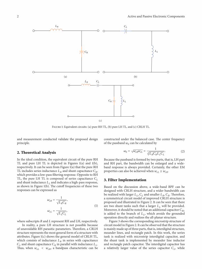
Figure 1: Equivalent circuits: (a) pure RH TL, (b) pure LH TL, and (c) CRLH TL.
and measurement conducted validate the proposed designprinciple.
2. Theoretical Analysis
In the ideal condition, the equivalent circuit of the pure RHTL and pure LH TL is depicted in Figures 1(a) and 1(b),respectively. It can be seen from Figure 1(a) that the pure RHTL includes series inductance 𝐿
𝑅and shunt capacitance 𝐶
𝑅,
which provides a low-pass filtering response. Opposite to RHTL, the pure LH TL is composed of series capacitance 𝐶
𝐿
and shunt inductance 𝐿𝐿and indicates a high-pass response,
as shown in Figure 1(b). The cutoff frequencies of these tworesponses can be expressed as
𝜔𝑐𝑅=
1
√𝐿𝑅𝐶𝑅
,
𝜔𝑐𝐿=
1
√𝐿𝐿𝐶𝐿
,
(1)
where subscripts 𝑅 and 𝐿 represent RH and LH, respectively.In reality, a pure LH structure is not possible because
of unavoidable RH parasitic parameters. Therefore, a CRLHstructure represents themost general form of a structure withattributes. Figure 1(c) shows the general model of CRLH TL,which consists of inductance 𝐿
𝑅in series with capacitance
𝐶𝐿and shunt capacitance 𝐶
𝑅in parallel with inductance 𝐿
𝐿.
Thus, when 𝑤𝑐𝐿< 𝑤𝑐𝑅, a bandpass characteristic can be
constructed under the balanced case. The center frequencyof the passband 𝑤
0can be calculated by
𝜔0= √𝜔𝑐𝑅𝜔𝑐𝐿=
1
4√𝐿𝑅𝐶𝑅𝐿𝐿𝐶𝐿
. (2)
Because the passband is formed by two parts, that is, LH partand RH part, the bandwidth can be enlarged and a wide-band response is always provided. Certainly, the other EMproperties can also be achieved when 𝑤
𝑐𝐿≥ 𝑤𝑐𝑅.
3. Filter Implementation
Based on the discussion above, a wide-band BPF can bedesigned with CRLH structure, and a wider bandwidth canbe realized with larger 𝐿
𝐿, 𝐶𝐿and smaller 𝐿
𝑅, 𝐶𝑅. Therefore,
a symmetrical circuit model of improved CRLH structure isproposed and illustrated in Figure 2. It can be seen that thereare two shunt tanks such that a larger 𝐿
𝐿will be provided.
Moreover, it should be noted that an additional capacitor𝐶𝑅1
is added to the branch of 𝐿𝐿, which avoids the grounded
operation directly and realizes the all-planar structure.Figure 3 shows the corresponding microstrip structure of
circuitmodel in Figure 2. It can be observed that the structureismainlymade up of three parts, that is, interdigital structure,meander lines, and rectangle patch. In this work, the seriestank is realized with microstrip interdigital capacitor, andthe shunt tank is implemented by meander line inductorand rectangle patch capacitor. The interdigital capacitor hasa relatively larger value of the series capacitor 𝐶
𝐿, while

Active and Passive Electronic Components 3
p
CL
LL
LRLR
LL
CR1 CR1
CR2 CR2
Figure 2: Symmetrical equivalent circuit of the improved CRLHstructure.
Interdigitalcapacitor
Meander lineinductor
Patch capacitor
w0
g0
h1
h1
L1
L2
L3
s1
s2 s3
Figure 3: Microstrip implementation of the improved CRLHstructure.
two meander lines provide a large shunt inductor 𝐿𝐿, which
ensure the wide-band BPF condition 𝑤𝑐𝐿< 𝑤𝑐𝑅. The other
parameters are carefully selected to meet the balanced CRLHrequirement, which averts the bandgap in the wide passbandrange.
EM simulated software Sonnet is applied to simulate thedesigned filter and optimize its size parameters. The Taconic-RF-35A2 substrate with a relative dielectric constant of 3.5and a thickness of 0.76mm is used. In this paper, a wide-bandBPF with passband ranges from 1.9GHz to 3.3 GHz (total3 dB bandwidth is 1.4 GHz) will be designed. According tothe parameters extracted and converted method described in[16, 17], the filter size can be obtained and finally optimizedby Sonnet as follows:𝑤
0= 𝑔0= 0.2, 𝑠
1= 2.6, 𝑠
2= 2.8, 𝑠
3= 3,
ℎ1= 0.5, ℎ
2= 3.5, 𝐿
1= 3.8, 𝐿
2= 4.7, and 𝐿
3= 3.5 (unit:
millimeters).
4. Results and Discussion
For demonstration purpose, the well-designed wide-bandfilter is fabricated on Taconic-RF-35A2 substrate. Without
Figure 4: Photograph of the proposed filter.
MeasurementSimulation
−40
−35
−30
−25
−20
−15
−10
−5
0
S-pa
ram
eter
s (dB
)
1.5 2.0 2.5 3.0 3.5 4.01.0Frequency (GHz)
Figure 5:Measured and simulated responses of the wide-band filter.
the via hole, it is easy to process the circuit with ordinarytechnology. Figure 4 depicts the photograph of the fabricatedfilter. The tapped coupling structure is used to design theinput/output structure and wedge shape is introduced forimpedance matching. The fabricated filter is measured bynetwork analyzer of CETC AV3629.
A comparison between simulation and measurement ispresented in Figure 5, where the red solid lines and bluedashed lines indicate the simulated and measured results,respectively. A wide-band bandpass response with the pass-band ranges from 1.91 to 3.32GHz is obtained and thecorresponding 3 dB bandwidth is about 51.9%.Themaximummeasured insertion loss is approximately 1.38 dB and thereturn loss in passband is better than 17 dB. Two transmissionzeros located at lower and upper side of passband enhancethe filter selectivity. A good agreement obtained between themeasured and simulated results indicates the validity of thedesign principle. Some discrepancy between the measuredand simulated data can be attributed to the inevitable inaccu-racy in fabrication and larger dielectric loss at high frequency.
Moreover, the complex propagation constant 𝛾 will bediscussed to interpret behaviors of the proposed CRLH

4 Active and Passive Electronic Components|𝛽
p|(r
ad)
0
1
2
3
4
|𝛼p|(N
P)
0.0
0.5
1.0
1.5
2.0
2.5
3.0
3.5
2.0 2.5 3.0 3.5 4.01.5Frequency (GHz)
Figure 6: Dispersion characteristic diagram of the designed filterwith improved CRLH structure.
device. According to circuit network analysis, 𝛾(𝑤) can beexpressed as
𝛾 (𝜔) = 𝛼 (𝜔) + 𝑗𝛽 (𝜔) =
cos−1 (𝐴)𝑝
, (3)
where 𝛼(𝑤) and 𝛽(𝑤) represent the attenuation factor andpropagation constant, respectively. 𝑝 is the total length ofimproved CRLH filter. Parameter 𝐴 is a matrix element ofABCD-matrix and it can be obtained from
𝐴 =
1 − 𝑆11𝑆22+ 𝑆12𝑆21
2𝑆21
. (4)
Therefore, 𝛾(𝑤) can be easily calculated from the simulatedor measured 𝑆 parameters.
Figure 6 shows 𝛾(𝑤) of the designed wide-band filter withCRLH TL structure. In general, the bigger the attenuationfactor 𝛼 is, the greater the electromagnetic wave is attenuated.If attenuation factor 𝛼 = 0, a passband will be presentedsince 𝛾(𝑤) = 𝑗𝛽(𝑤) is an imaginary. Otherwise, a stopbandoccurs in certain frequency range. So, a passband occurswithin the frequency ranges from 1.9 to 3.3 GHz.On the otherhand, it can be found that the product of group velocity andphase velocity V
𝑔V𝑝< 0 (V
𝑔= 𝜕𝜔/𝜕𝛽, V
𝑝= 𝜔/𝛽) in the
frequency range from 1.91 to 2.12GHz and shows the LHperformance. Similarly, it can be obtained that V
𝑔V𝑝> 0 in
the frequency range from 2.12 to 3.32GHz and indicates theRH performance.
5. Conclusions
In this paper, a wide-band BPF is designed with the improvedCRLH TL. Additional patch capacitance is added to removetraditional via hole, which reduces the fabrication difficultyand circuit loss. The filter is simulated and optimized by EMsoftware Sonnet. Good agreement between simulation andmeasurement validates the validity of the proposed designprinciple. To observe the LHproperty, the dispersion diagramis given and explained in the paper.
Competing Interests
The authors declare that there are no competing interestsregarding the publication of this paper.
Acknowledgments
This work was supported by the National Natural ScienceFoundation of China under Grant 61461020 and Interna-tional Cooperation Funds and Science (nos. 20133BDH80007,20141BDH80002) and Technology Innovation Team ofJiangxi Province (no. 20142BCB24004) and Research Fundsof East China Jiaotong University (no. 15XX03).
References
[1] N. Engheta and R.W. Ziolkowsiki, ElectromagneticMetamateri-als Physics and Engineering Explorations, Wiley and IEEE Press,2006.
[2] “Breakthrough of the year. The runners-up,” Science, vol. 338,no. 6114, pp. 1525–1532, 2012.
[3] R. A. Shelby,D. R. Smith, and S. Schultz, “Experimental verifica-tion of a negative index of refraction,” Science, vol. 292, no. 5514,pp. 77–79, 2001.
[4] A. Lai, C. Caloz, and T. Itoh, “Composite right/left-handedtransmission line metamaterials,” IEEE Microwave Magazine,vol. 5, no. 3, pp. 34–50, 2004.
[5] C. Caloz and T. Itoh, “Application of the transmission linetheory of left-handed (LH) materials to the realization of amicrostrip ‘LH line’,” in Proceedings of the IEEE Antennas andPropagation Society International Symposium, vol. 2, pp. 412–415, IEEE, usa, June 2002.
[6] G. V. Eleftheriades, O. Siddiqui, and A. K. Iyer, “Transmissionline models for negative refractive index media and associatedimplementations without excess resonators,” IEEE Microwaveand Wireless Components Letters, vol. 13, no. 2, pp. 51–53, 2003.
[7] C. Caloz and T. Itoh, Electromagetic Metamaterials: Transmis-sion Line Theory and Microwave Applications, John Wiley &Sons and IEEE Press, 2006.
[8] W. J. Feng, W. Q. Che, and Q. Xue, “Transversal signal interac-tion: overview of high-performance wideband bandpass filters,”IEEE Microwave Magazine, vol. 15, no. 2, pp. 84–96, 2014.
[9] H. Wang, Q.-X. Chu, and J.-Q. Gong, “A compact widebandmicrostrip filter using folded multiple-mode resonator,” IEEEMicrowave and Wireless Components Letters, vol. 19, no. 5, pp.287–289, 2009.
[10] S.-J. Sun, B. Wu, T. Su, K. Deng, and C.-H. Liang, “Wide-band dual-mode microstrip filter using short-ended resonatorwith centrally loaded inductive stub,” IEEE Transactions onMicrowave Theory and Techniques, vol. 60, no. 12, pp. 3667–3673, 2012.
[11] S. Sun, L. Zhu, and H.-H. Tan, “A compact wide-band bandpassfilter using transversal resonator and asymmetrical interdigitalcoupled lines,” IEEE Microwave and Wireless Components Let-ters, vol. 18, no. 3, pp. 173–175, 2008.
[12] R. Gomez-Garcıa, M. Sanchez-Renedo, B. Jarry, J. Lintignat,and B. Barelaud, “A class of microwave transversal signal-interference dual passband planar filters,” IEEE Microwave andWireless Components Letters, vol. 19, no. 3, pp. 158–160, 2009.
[13] B. Li, X. W. Dai, B. Wu, and C. H. Liang, “Ultra wideband filterdesign based on composite right-/left-handed transmission

Active and Passive Electronic Components 5
line,” Microwave and Optical Technology Letters, vol. 49, no. 10,pp. 2379–2381, 2007.
[14] S.-H.Oh,K.-T.Kim, J.-H. Lee, S. Kahng, andH.-S. Kim, “Designof the miniaturized ultra-wide band (UWB) filter using themetamaterial characteristic,” in Proceedings of the 3rd Asia-Pacific Microwave Conference (APMC ’13), pp. 954–956, IEEE,November 2013.
[15] H. W. Liu, P. Wen, S. S. Zhu, B. P. Ren, and Y. S. He, “High-temperature superconducting composite right/left-handed res-onator,” IEEE Trasaction on Applied Superconductivity, vol. 26,no. 3, Article ID 1500204, 2016.
[16] B. Li, J. P. Yang, and W. Wu, “A planar microstrip implementa-tion of dual-composite right/left handed transmission line,” inProceedings of the International Conference on Microwave andMillimeter Wave Technology (ICMMT ’08), pp. 1617–1619, IEEE,Nanjing, China, April 2008.
[17] J. S. Hong andM. J. Lanaster,Microwave Filter for RF/MicrowaveApplication, John Wiley & Sons, New York, NY, USA, 2001.

International Journal of
AerospaceEngineeringHindawi Publishing Corporationhttp://www.hindawi.com Volume 2014
RoboticsJournal of
Hindawi Publishing Corporationhttp://www.hindawi.com Volume 2014
Hindawi Publishing Corporationhttp://www.hindawi.com Volume 2014
Active and Passive Electronic Components
Control Scienceand Engineering
Journal of
Hindawi Publishing Corporationhttp://www.hindawi.com Volume 2014
International Journal of
RotatingMachinery
Hindawi Publishing Corporationhttp://www.hindawi.com Volume 2014
Hindawi Publishing Corporation http://www.hindawi.com
Journal ofEngineeringVolume 2014
Submit your manuscripts athttp://www.hindawi.com
VLSI Design
Hindawi Publishing Corporationhttp://www.hindawi.com Volume 2014
Hindawi Publishing Corporationhttp://www.hindawi.com Volume 2014
Shock and Vibration
Hindawi Publishing Corporationhttp://www.hindawi.com Volume 2014
Civil EngineeringAdvances in
Acoustics and VibrationAdvances in
Hindawi Publishing Corporationhttp://www.hindawi.com Volume 2014
Hindawi Publishing Corporationhttp://www.hindawi.com Volume 2014
Electrical and Computer Engineering
Journal of
Advances inOptoElectronics
Hindawi Publishing Corporation http://www.hindawi.com
Volume 2014
The Scientific World JournalHindawi Publishing Corporation http://www.hindawi.com Volume 2014
SensorsJournal of
Hindawi Publishing Corporationhttp://www.hindawi.com Volume 2014
Modelling & Simulation in EngineeringHindawi Publishing Corporation http://www.hindawi.com Volume 2014
Hindawi Publishing Corporationhttp://www.hindawi.com Volume 2014
Chemical EngineeringInternational Journal of Antennas and
Propagation
International Journal of
Hindawi Publishing Corporationhttp://www.hindawi.com Volume 2014
Hindawi Publishing Corporationhttp://www.hindawi.com Volume 2014
Navigation and Observation
International Journal of
Hindawi Publishing Corporationhttp://www.hindawi.com Volume 2014
DistributedSensor Networks
International Journal of