Dual-Mode Dual-Band Microstrip Bandpass Filter Based on ... · Dual-Mode Dual-Band Microstrip...
7
RADIOENGINEERING, VOL. 21, NO. 2, JUNE 2012 617 Dual-Mode Dual-Band Microstrip Bandpass Filter Based on Fourth Iteration T-Square Fractal and Shorting Pin Emad S. AHMED Dept. of Electrical Engineering, University of Technology, Baghdad, Iraq [email protected] Abstract. A new class of a dual mode microstrip fractal resonator is proposed and developed for miniaturization of the dual band bandpass filter. The perimeter of the pro- posed resonator is increased by employing fourth iteration T-square fractal shape. Consequently the lower resonant frequency of the filter is decreased without increasing the usable space. The self similarity of the usable structure enables it to produce the two degenerate modes which are coupled using the proper perturbation technique. The shorting pin is placed at the null in the surface current distribution at the center of the resonator. This shorting pin is coactively coupled to the resonant circuit of the resonator, effectively coupled to the lower degenerate mode and reduces the lower edge band resonant fre- quency. By adjusting the resonator dimensions and the size of the shorting pin, the resonant frequency and the out-of- band rejection around the transmission bands can be con- trolled to meet the design requirements. The simulated response of the designed filter has two transmission bands; the first band is from 2.34-3.65 GHz with resonant fre- quencies at 2.47 GHz and 3.55 GHz, the second band is from 4.37-5.324 GHz with resonant frequencies at 4.5 GHz and 5.13 GHz. In the pass bands, the group delay is less than 0.65 ns. The proposed filter can be applied to WLAN (2.4 GHz and 5.2 GHz) and WiMAX (3.5 GHz) and Blue- tooth and ZigBee (4.9 GHz). Keywords Microstrip filters, fractals, dual-mode filters, dual- band filters, shorting pin. 1. 0BIntroduction Microwave filters are basic building blocks in various wireless systems. With the rapid development of modern wireless communication, more planar filters with excellent performances and miniaturization are required. In the re- cent years, dual-mode resonators have been increasingly used in wireless communication systems and other RF applications. Most of the known dual-mode resonator structures are built using microstrip technique. The microstrip dual mode filters can be performed either by two degenerate modes or non degenerate modes [1]. In degenerate dual mode case, the bandpass filter response can be obtained through the excitation of the two degenerate modes by asymmetrical feed lines and adjusting the coupling between the two modes by adding suitable form of perturbation within the resonators [2]. The relative size and type of perturbation have a direct effect on bandwidth and/or transmission zero location of a given dual mode response. Variety of micro- strip dual mode bandpass filters has been proposed over the past decade [3-12]. The main advantage of the dual-mode patches and loops is that the degenerate modes can be split by having a small patch attached to the resonator corner or by having a square cut (perturbation element) in one of the resonator corners. Moreover, the strength of the coupling between the degenerate modes depends on the size of the perturba- tion element [13]. The nature of the coupling between the modes depends on the shape of the perturbation element, so by having a cut at one corner of the resonator; an induc- tive coupling between the modes is induced. While attach- ing a small patch at the one corner will induce a capacitive coupling between the modes. Furthermore, the position of the attenuation poles can also be adjusted by coupling the dual-mode resonator with a feed line location not at the center of the arms of the resonator [1], [14]. Some of modern multi functional communication systems work with signals spread at the same time with several frequency bands; therefore, these systems must incorporate dual-band, triple-band or multi-band filters. Dual band filters have become an attractive component for wireless communication products at RF/microwave fre- quencies [15]. For example, wireless local area network (WLAN) products for IEEE 802.11b and IEEE 802.11g standards operate in the unlicensed industrial-scientific- medical (ISM) 2.4 GHz band and products of IEEE 802.11a operate in the ISM 5.7 GHz band [16]. The basic principle for designing multi-band micro- strip filters is the selection and application of all sorts of resonant modes. Certain perturbation element and feed method can change the patch resonator original resonant frequencies of different resonant modes. If several resonant modes are coupled each other simultaneously, the reso- nance of the other resonant modes is shifted to further locations. As a result, a wider filter bandwidth may be implemented compared with a single mode or dual mode
Transcript of Dual-Mode Dual-Band Microstrip Bandpass Filter Based on ... · Dual-Mode Dual-Band Microstrip...
RADIOENGINEERING, VOL. 21, NO. 2, JUNE 2012 617
Dual-Mode Dual-Band Microstrip Bandpass Filter Based on Fourth Iteration T-Square Fractal and Shorting Pin
Emad S. AHMED
Dept. of Electrical Engineering, University of Technology, Baghdad, Iraq
Abstract. A new class of a dual mode microstrip fractal resonator is proposed and developed for miniaturization of the dual band bandpass filter. The perimeter of the pro-posed resonator is increased by employing fourth iteration T-square fractal shape. Consequently the lower resonant frequency of the filter is decreased without increasing the usable space. The self similarity of the usable structure enables it to produce the two degenerate modes which are coupled using the proper perturbation technique. The shorting pin is placed at the null in the surface current distribution at the center of the resonator. This shorting pin is coactively coupled to the resonant circuit of the resonator, effectively coupled to the lower degenerate mode and reduces the lower edge band resonant fre-quency. By adjusting the resonator dimensions and the size of the shorting pin, the resonant frequency and the out-of-band rejection around the transmission bands can be con-trolled to meet the design requirements. The simulated response of the designed filter has two transmission bands; the first band is from 2.34-3.65 GHz with resonant fre-quencies at 2.47 GHz and 3.55 GHz, the second band is from 4.37-5.324 GHz with resonant frequencies at 4.5 GHz and 5.13 GHz. In the pass bands, the group delay is less than 0.65 ns. The proposed filter can be applied to WLAN (2.4 GHz and 5.2 GHz) and WiMAX (3.5 GHz) and Blue-tooth and ZigBee (4.9 GHz).
Keywords Microstrip filters, fractals, dual-mode filters, dual-band filters, shorting pin.
1. 0BIntroduction Microwave filters are basic building blocks in various
wireless systems. With the rapid development of modern wireless communication, more planar filters with excellent performances and miniaturization are required. In the re-cent years, dual-mode resonators have been increasingly used in wireless communication systems and other RF applications.
Most of the known dual-mode resonator structures are built using microstrip technique. The microstrip dual mode filters can be performed either by two degenerate modes or
non degenerate modes [1]. In degenerate dual mode case, the bandpass filter response can be obtained through the excitation of the two degenerate modes by asymmetrical feed lines and adjusting the coupling between the two modes by adding suitable form of perturbation within the resonators [2]. The relative size and type of perturbation have a direct effect on bandwidth and/or transmission zero location of a given dual mode response. Variety of micro-strip dual mode bandpass filters has been proposed over the past decade [3-12].
The main advantage of the dual-mode patches and loops is that the degenerate modes can be split by having a small patch attached to the resonator corner or by having a square cut (perturbation element) in one of the resonator corners. Moreover, the strength of the coupling between the degenerate modes depends on the size of the perturba-tion element [13]. The nature of the coupling between the modes depends on the shape of the perturbation element, so by having a cut at one corner of the resonator; an induc-tive coupling between the modes is induced. While attach-ing a small patch at the one corner will induce a capacitive coupling between the modes. Furthermore, the position of the attenuation poles can also be adjusted by coupling the dual-mode resonator with a feed line location not at the center of the arms of the resonator [1], [14].
Some of modern multi functional communication systems work with signals spread at the same time with several frequency bands; therefore, these systems must incorporate dual-band, triple-band or multi-band filters. Dual band filters have become an attractive component for wireless communication products at RF/microwave fre-quencies [15]. For example, wireless local area network (WLAN) products for IEEE 802.11b and IEEE 802.11g standards operate in the unlicensed industrial-scientific-medical (ISM) 2.4 GHz band and products of IEEE 802.11a operate in the ISM 5.7 GHz band [16].
The basic principle for designing multi-band micro-strip filters is the selection and application of all sorts of resonant modes. Certain perturbation element and feed method can change the patch resonator original resonant frequencies of different resonant modes. If several resonant modes are coupled each other simultaneously, the reso-nance of the other resonant modes is shifted to further locations. As a result, a wider filter bandwidth may be implemented compared with a single mode or dual mode
618 E. S. AHMED, DUAL-MODE DUAL-BAND MICROSTRIP BANDPASS FILTER BASED ON 4TH ITERATION T-SQUARE FRACTAL…
operation when using the same permittivity substrate [17]. Yang and et al. [18] uses shorting pins to enhance the filter bandwidth. By adjusting the patch dimensions and posi-tions of the shorting pins, the center frequency and equivalent inductance and capacitance can meet design requirements. Based on the proposed structure and its equivalent circuit, a wideband 3-pole notch filter is de-signed.
In many applications, it is desirable for the dimen-sions of the microstrip patch to be a small fraction of the space wavelength. The resonant length of the microstrip patch is approximately /2, where is a wavelength in dielectric substrate. It follows that the size of the patch can be reduced by using substrate material with high dielectric constant. However, the resulting patch will have a narrow impedance bandwidth. This motivated the search for other size reduction methods. [19]. To reduce the size of the patch antenna without disturbing the substrate material permittivity value, Kumar and et al. [20] use some special techniques like shorting pin, shorting plate, shorting wall and some other slot models. They present two models, shorting pin and shorting plate at a fixed resonant fre-quency.
Miniaturization of microwave filters is one of funda-mental requirements in communication systems. To meet these demands, intensive research efforts have been fo-cused on achieving compact low loss bandpass filters for wireless system applications. Many research works based on the circular ring, square loop, meandered loop resona-tor, circular disk, and square patches were reported [21].
Fractal geometry has found extensive applications in almost all the fields of science, technology and art since the pioneering work of Mandelbrot about three decades ago [22]. Fractals represent a class of geometries with unique properties that can be attractive for microwave, semicon-ductor and MEMS designers [23], [24]. Fractal geometry has been applied widely in the field of antenna and passive microwave circuit design for miniaturization and multi-mode operations. However, when it is applied to RF de-vices for miniaturization, there is some limitation in the fractal order because the variation of the electrical length is relatively smaller compared to that of the operating fre-quency [25], [26].
In this paper, a novel microstrip resonator with fractal geometry defined by T-square fractal with a shorting pin is investigated for a multimode operation microstrip bandpass filter. The filter is analyzed and solved in terms of the cav-ity model using finite element method (FEM) and results are refined by full-wave simulator CST Microwave Studio 2010.
2. T-Square Fractal Generation Process Fractals are characterized by two properties: the
iteration factor and the iteration order. The iteration factor
represents the construction law of the fractal geometry generation, and the iteration order depicts how many itera-tion processes are carried out. An L-system (Lindenmayer system) has been found very useful for generating the ge-ometry of various fractal structures [27]. There’s an ana-logue of L-systems for things more complicated than curves. One simple example, called a geometric L-system, which is useful for generating a certain kind of iterated function fractal. It can be demonstrated in the context of an interesting fractal figure, called the T-square fractal.
The procedure to create a T-square starts off with a square canvas on which one is going to draw. Calling the generate function, it is needed to pass to it the coordinates of the first square, which, to get the best fit into the canvas, the lengths of the sides of the square denoted by L, to be half the canvas sides, and then center the square, essen-tially making the top left corner a quarter of the way to the right and down of the origin. The first thing to do is draw a solid square using selected coordinates. Now, until reach-ing the desired recursion depth, four new squares have to be generated, which have half the width and height of the original square, and make the centers of each of these squares to be centered on each of the four corners of the original square. This process is then repeated until we have recurred far enough. These procedures are shown in Fig. 1.
Fig. 1. T-square fractals for iteration factor from k = 0 to 4.
The enclosed area of the T-square shape fractal after k-th iterations are derived and given by:
,....3,2,1,04/3 2
0
kLAnk
nk
(1)
The perimeter of the T-square shape fractal after k-th iterations is derived and given by:
,....3,2,1,02
33
1
1
kPPk
k
kk (2)
where L is the width of the initiator and P0 = 4L is the perimeter of the initiator.
3. Characteristics of Dual-Mode Microstrip Resonator A microstrip dual mode resonator in any shape, hav-
ing symmetry in two dimensions, can be described by Wheeler’s cavity model [28]. In this model, the top and bottom of the cavity are complete electric walls and the outer sides are perfect magnetic walls. Electromagnetic field patterns of the TM mode in microstrip resonator hav-ing no variation along the dielectric thickness direction, and the wave equation can be written as [29]:

RADIOENGINEERING, VOL. 21, NO. 2, JUNE 2012 619
0)(2
2
2
2
zmn Ekyx
(3)
where Ez is the electric field component of z direction (along dielectric thickness direction), kmn is wave-number, and the integers m and n determine the resonant modes. kmn can be expressed as [28]
22 )()(a
n
a
mkmn
(4)
where a is the effective width of the cavity. Different modes introduce limitless number of resonant frequencies, which can be expressed by:
eff
mnr
ckf
2 (5)
where c is the velocity of light in free space, εeff is the ef-fective dielectric coefficient of the used substrate and given by [30]:
)/101
1(
2
1
2
1
ahrr
eff
(6)
where εr is the relative dielectric constant and h is the sub-strate thickness. In particular, for a square geometry, every mode is degenerate since modes (m, n) and (n, m) have the same resonant frequency. Thus when the cavity is excited at a given resonant frequency, both modes may exist to produce an interesting complex field distribution. How-ever, if there is a slight imperfection in the construction, the degenerate resonant frequency may split into two close ones so that their corresponding modes are excited simul-taneously as the frequency sweeps through their neighbor-hood [31].
4. New Fractal Based Bandpass Filter with Dual-Band Operation
The proposed bandpass filter based on fourth iteration T-square fractal is depicted in Fig. 2. The filter has been conducted for ISM, WiMax and WLAN operating fre-quency of 2.4 GHz, 3.5 GHz, and 5.2 GHz. The filter is designed on a substrate of 20 mm13 mm with 1.27 mm thickness and a relative dielectric constant of 10.8. The resonator is excited by using a gap-coupling method, where port 1 is the input port and port 2 is the output port.
The basic principle for designing a microstrip filter by using a patch resonator is the selection and application of all sorts of resonant modes. The fractal shape of the reso-nator and port feed method can change the patch resonator original resonant frequencies of different resonant modes. Based on the above principle and with the help of EM simulator, the optimized dimensions of the proposed filter are: L = 4.5 mm, W1 = 5 mm, W2 = 0.6 mm, S = 0.2 mm, L1 = 8.75 mm.
Using (2), the k-th iteration perimeter P4 of the fractal shape resonator is 36.5L. The effective width of the cavity a = (36.5L)/4, then a = 41.0625 mm when L = 4.5 mm.
By substituting the proper values for m and n, equal frequencies can be obtained. For instance, f10 = f01 = 1.142 GHz, f20 = f02 = 2.285 GHz, f03 = f30 = 3.428 GHz, f04 = f40 = 4.57 GHz, f05 = f50 = 5.713 GHz, and that of the higher order modes such as f12 = f21 = 2.555 GHz, f13 = f31 = 3.613 GHz, f14 = f41 = 4.711 GHz, f15 = f51 = 5.826 GHz. These modes are degenerate modes that have the same resonant frequency with orthogonal field distributions.
Fig. 2. Multimode BPF based on T-square fractal configura-
tion.
5. Performance Evaluation Filter structure depicted in Fig. 2 has been analyzed
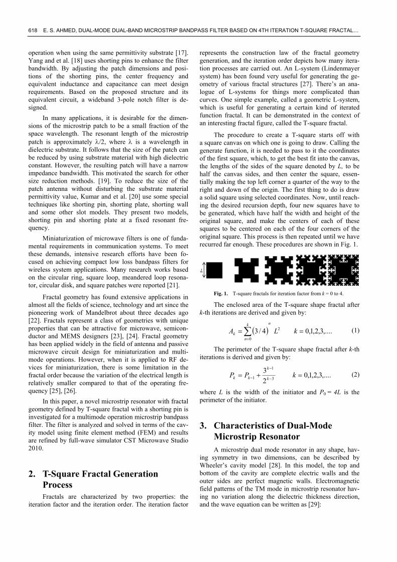
using the CST Microwave Studio 2010 electromagnetic simulator. The fractal shape of the proposed patch resona-tor adds some perturbations to the symmetry of the struc-ture, so that the field distributions of the degenerate mode will be no longer orthogonal, and they are coupled each other. The corresponding simulation results of return loss and transmission response are shown in Fig. 3. In this fig-ure, two bands with -10 dB return loss can be observed clearly. The first is from 3.438-3.641 GHz centered at 3.539 GHz with -32.43 dB return loss and -0.46 dB inser-tion loss. The second one is from 4.3-5.273 GHz with two resonance frequencies at 4.503 GHz and 5.162 GHz with a return loss of -32.49 dB and -24.29 dB, respectively and insertion loss of -0.84 dB.
The transmission zeros are symmetrically located around the upper band on 3.95 GHz and 6.105 GHz with -32.33 dB and -49.31 dB insertion loss, respectively. On the other hand, the lower band transmission zeros are asymmetrically located at 2 GHz and 3.95 GHz with insertion loss of -7.17 dB and -32.33 dB, respectively. The out-of-lower band rejection level is needed to be decreased to an acceptable level.
However, the responses in Fig. 3 and their consequent poles and zeroes could be controlled through the variation of the coupling between the degenerated modes.
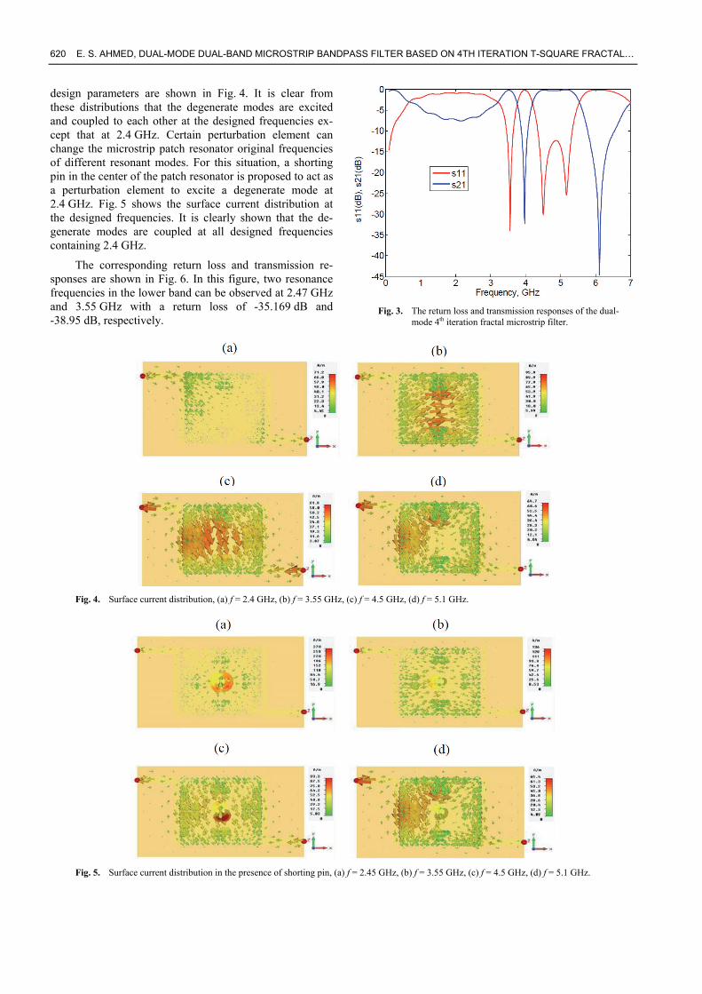
The surface current distributions using the EM simu-lator for 4th iteration T-square fractal bandpass filter at the
620 E. S. AHMED, DUAL-MODE DUAL-BAND MICROSTRIP BANDPASS FILTER BASED ON 4TH ITERATION T-SQUARE FRACTAL…
design parameters are shown in Fig. 4. It is clear from these distributions that the degenerate modes are excited and coupled to each other at the designed frequencies ex-cept that at 2.4 GHz. Certain perturbation element can change the microstrip patch resonator original frequencies of different resonant modes. For this situation, a shorting pin in the center of the patch resonator is proposed to act as a perturbation element to excite a degenerate mode at 2.4 GHz. Fig. 5 shows the surface current distribution at the designed frequencies. It is clearly shown that the de-generate modes are coupled at all designed frequencies containing 2.4 GHz.
The corresponding return loss and transmission re-sponses are shown in Fig. 6. In this figure, two resonance frequencies in the lower band can be observed at 2.47 GHz and 3.55 GHz with a return loss of -35.169 dB and -38.95 dB, respectively.
Fig. 3. The return loss and transmission responses of the dual-
mode 4th iteration fractal microstrip filter.
Fig. 4. Surface current distribution, (a) f = 2.4 GHz, (b) f = 3.55 GHz, (c) f = 4.5 GHz, (d) f = 5.1 GHz.
Fig. 5. Surface current distribution in the presence of shorting pin, (a) f = 2.45 GHz, (b) f = 3.55 GHz, (c) f = 4.5 GHz, (d) f = 5.1 GHz.
RADIOENGINEERING, VOL. 21, NO. 2, JUNE 2012 621
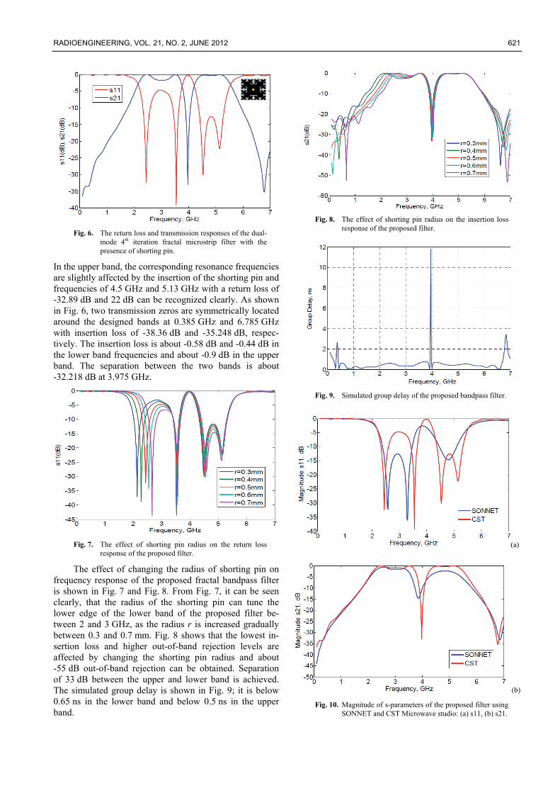
Fig. 6. The return loss and transmission responses of the dual-
mode 4th iteration fractal microstrip filter with the presence of shorting pin.
In the upper band, the corresponding resonance frequencies are slightly affected by the insertion of the shorting pin and frequencies of 4.5 GHz and 5.13 GHz with a return loss of -32.89 dB and 22 dB can be recognized clearly. As shown in Fig. 6, two transmission zeros are symmetrically located around the designed bands at 0.385 GHz and 6.785 GHz with insertion loss of -38.36 dB and -35.248 dB, respec-tively. The insertion loss is about -0.58 dB and -0.44 dB in the lower band frequencies and about -0.9 dB in the upper band. The separation between the two bands is about -32.218 dB at 3.975 GHz.
Fig. 7. The effect of shorting pin radius on the return loss
response of the proposed filter.
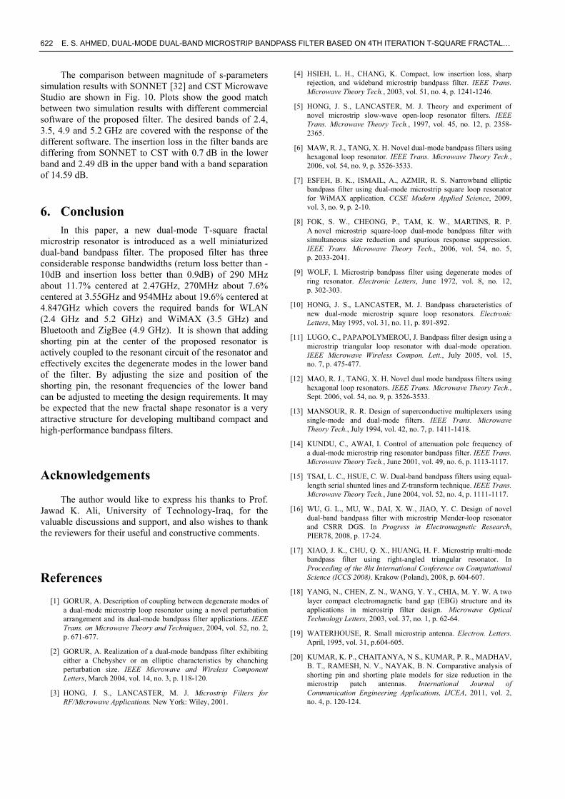
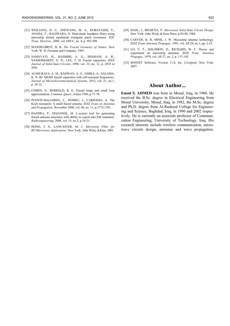
The effect of changing the radius of shorting pin on frequency response of the proposed fractal bandpass filter is shown in Fig. 7 and Fig. 8. From Fig. 7, it can be seen clearly, that the radius of the shorting pin can tune the lower edge of the lower band of the proposed filter be-tween 2 and 3 GHz, as the radius r is increased gradually between 0.3 and 0.7 mm. Fig. 8 shows that the lowest in-sertion loss and higher out-of-band rejection levels are affected by changing the shorting pin radius and about -55 dB out-of-band rejection can be obtained. Separation of 33 dB between the upper and lower band is achieved. The simulated group delay is shown in Fig. 9; it is below 0.65 ns in the lower band and below 0.5 ns in the upper band.
Fig. 8. The effect of shorting pin radius on the insertion loss
response of the proposed filter.
Fig. 9. Simulated group delay of the proposed bandpass filter.
(a)
(b)
Fig. 10. Magnitude of s-parameters of the proposed filter using SONNET and CST Microwave studio: (a) s11, (b) s21.
622 E. S. AHMED, DUAL-MODE DUAL-BAND MICROSTRIP BANDPASS FILTER BASED ON 4TH ITERATION T-SQUARE FRACTAL…
The comparison between magnitude of s-parameters simulation results with SONNET [32] and CST Microwave Studio are shown in Fig. 10. Plots show the good match between two simulation results with different commercial software of the proposed filter. The desired bands of 2.4, 3.5, 4.9 and 5.2 GHz are covered with the response of the different software. The insertion loss in the filter bands are differing from SONNET to CST with 0.7 dB in the lower band and 2.49 dB in the upper band with a band separation of 14.59 dB.
6. Conclusion In this paper, a new dual-mode T-square fractal
microstrip resonator is introduced as a well miniaturized dual-band bandpass filter. The proposed filter has three considerable response bandwidths (return loss better than -10dB and insertion loss better than 0.9dB) of 290 MHz about 11.7% centered at 2.47GHz, 270MHz about 7.6% centered at 3.55GHz and 954MHz about 19.6% centered at 4.847GHz which covers the required bands for WLAN (2.4 GHz and 5.2 GHz) and WiMAX (3.5 GHz) and Bluetooth and ZigBee (4.9 GHz). It is shown that adding shorting pin at the center of the proposed resonator is actively coupled to the resonant circuit of the resonator and effectively excites the degenerate modes in the lower band of the filter. By adjusting the size and position of the shorting pin, the resonant frequencies of the lower band can be adjusted to meeting the design requirements. It may be expected that the new fractal shape resonator is a very attractive structure for developing multiband compact and high-performance bandpass filters.
Acknowledgements
The author would like to express his thanks to Prof. Jawad K. Ali, University of Technology-Iraq, for the valuable discussions and support, and also wishes to thank the reviewers for their useful and constructive comments.
References
[1] GORUR, A. Description of coupling between degenerate modes of a dual-mode microstrip loop resonator using a novel perturbation arrangement and its dual-mode bandpass filter applications. IEEE Trans. on Microwave Theory and Techniques, 2004, vol. 52, no. 2, p. 671-677.
[2] GORUR, A. Realization of a dual-mode bandpass filter exhibiting either a Chebyshev or an elliptic characteristics by chanching perturbation size. IEEE Microwave and Wireless Component Letters, March 2004, vol. 14, no. 3, p. 118-120.
[3] HONG, J. S., LANCASTER, M. J. Microstrip Filters for RF/Microwave Applications. New York: Wiley, 2001.
[4] HSIEH, L. H., CHANG, K. Compact, low insertion loss, sharp rejection, and wideband microstrip bandpass filter. IEEE Trans. Microwave Theory Tech., 2003, vol. 51, no. 4, p. 1241-1246.
[5] HONG, J. S., LANCASTER, M. J. Theory and experiment of novel microstrip slow-wave open-loop resonator filters. IEEE Trans. Microwave Theory Tech., 1997, vol. 45, no. 12, p. 2358-2365.
[6] MAW, R. J., TANG, X. H. Novel dual-mode bandpass filters using hexagonal loop resonator. IEEE Trans. Microwave Theory Tech., 2006, vol. 54, no. 9, p. 3526-3533.
[7] ESFEH, B. K., ISMAIL, A., AZMIR, R. S. Narrowband elliptic bandpass filter using dual-mode microstrip square loop resonator for WiMAX application. CCSE Modern Applied Science, 2009, vol. 3, no. 9, p. 2-10.
[8] FOK, S. W., CHEONG, P., TAM, K. W., MARTINS, R. P. A novel microstrip square-loop dual-mode bandpass filter with simultaneous size reduction and spurious response suppression. IEEE Trans. Microwave Theory Tech., 2006, vol. 54, no. 5, p. 2033-2041.
[9] WOLF, I. Microstrip bandpass filter using degenerate modes of ring resonator. Electronic Letters, June 1972, vol. 8, no. 12, p. 302-303.
[10] HONG, J. S., LANCASTER, M. J. Bandpass characteristics of new dual-mode microstrip square loop resonators. Electronic Letters, May 1995, vol. 31, no. 11, p. 891-892.
[11] LUGO, C., PAPAPOLYMEROU, J. Bandpass filter design using a microstrip triangular loop resonator with dual-mode operation. IEEE Microwave Wireless Compon. Lett., July 2005, vol. 15, no. 7, p. 475-477.
[12] MAO, R. J., TANG, X. H. Novel dual mode bandpass filters using hexagonal loop resonators. IEEE Trans. Microwave Theory Tech., Sept. 2006, vol. 54, no. 9, p. 3526-3533.
[13] MANSOUR, R. R. Design of superconductive multiplexers using single-mode and dual-mode filters. IEEE Trans. Microwave Theory Tech., July 1994, vol. 42, no. 7, p. 1411-1418.
[14] KUNDU, C., AWAI, I. Control of attenuation pole frequency of a dual-mode microstrip ring resonator bandpass filter. IEEE Trans. Microwave Theory Tech., June 2001, vol. 49, no. 6, p. 1113-1117.
[15] TSAI, L. C., HSUE, C. W. Dual-band bandpass filters using equal-length serial shunted lines and Z-transform technique. IEEE Trans. Microwave Theory Tech., June 2004, vol. 52, no. 4, p. 1111-1117.
[16] WU, G. L., MU, W., DAI, X. W., JIAO, Y. C. Design of novel dual-band bandpass filter with microstrip Mender-loop resonator and CSRR DGS. In Progress in Electromagnetic Research, PIER78, 2008, p. 17-24.
[17] XIAO, J. K., CHU, Q. X., HUANG, H. F. Microstrip multi-mode bandpass filter using right-angled triangular resonator. In Proceeding of the 8ht International Conference on Computational Science (ICCS 2008). Krakow (Poland), 2008, p. 604-607.
[18] YANG, N., CHEN, Z. N., WANG, Y. Y., CHIA, M. Y. W. A two layer compact electromagnetic band gap (EBG) structure and its applications in microstrip filter design. Microwave Optical Technology Letters, 2003, vol. 37, no. 1, p. 62-64.
[19] WATERHOUSE, R. Small microstrip antenna. Electron. Letters. April, 1995, vol. 31, p.604-605.
[20] KUMAR, K. P., CHAITANYA, N S., KUMAR, P. R., MADHAV, B. T., RAMESH, N. V., NAYAK, B. N. Comparative analysis of shorting pin and shorting plate models for size reduction in the microstrip patch antennas. International Journal of Communication Engineering Applications, IJCEA, 2011, vol. 2, no. 4, p. 120-124.
RADIOENGINEERING, VOL. 21, NO. 2, JUNE 2012 623
[21] WEILIANG, H. U., ZHEWANG, M. A., KOBAYASHI, Y., ANADA, T., HAGIWARA, G. Dual-mode bandpass filters using microstrip slotted equilateral triangular patch resonators. IEIC Trans. Electron., 2006, vol. E89-C, no. 4, p. 503-508.
[22] MANDELBROT, B. B. The Fractal Geometry of Nature. New York: W. H. Freeman and Company, 1983.
[23] SAMAVATI, H., HAJIMIRI, A. G., SHAHANI, A. R., NASSERBAKHT, G. N., LEE, T. H. Fractal capacitors. IEEE Journal of Solid State Circuits, 1998, vol. 33, no. 12, p. 2035 to 2041.
[24] ALSHURAFA, A. M., RADWAN, A. G., EMIRA, A., SALAMA, K. N. RF MEMS fractal capacitors with self-resonant frequencies. Journal of Microelectromechanical Systems, 2012, vol. 21, no.1, p. 10-12.
[25] COHEN, N., HOHFELD, R. G. Fractal loops and small loop approximation. Commun. Quart., winter 1996, p 77-78.
[26] PUENTE-BALIARDA, C., ROMEU, J., CARDAMA, A. The Koch monopole: A small fractal antenna. IEEE Trans on Antennas and Propagation, November 2000, vol. 48, no. 11, p.1773-1781.
[27] HAZDRA, P., MAZANEK, M. L-system tool for generating fractal antenna structures with ability to export into EM simulator. Radioengineering, 2008, vol. 15, no.2, p.18-21.
[28] HONG, J. S., LANCASTER, M. J. Microstrip Filter for RF/Microwave Applications. New York: John Wiley &Sons, 2001.
[29] BAHL, I., BHARTIA, P. Microwave Solid State Circuit Design. New York: John Wiely & Sons Press, p.84-88, 1988.
[30] CARVER, K. R, MINK, J. W. Microstrip antenna technology. IEEE Trans Antennas Propagat., 1981, vol. AP.29, no.1, pp. 2-23.
[31] LO, Y. T., SOLOMON, D., RICHARD, W. F. Theory and experiment on microstrip antennas. IEEE Trans. Antennas Propagat., 1979, vol. AP.27, no. 2, p. 137-145.
[32] SONNET Software, Version 11.0, Inc. Liverpool, New York, 2007.
About Author... Emad S. AHMED was born in Mosul, Iraq, in 1960. He received the B.Sc. degree in Electrical Engineering from Mosul University, Mosul, Iraq, in 1982, the M.Sc. degree and Ph.D. degree from Al-Rasheed College for Engineer-ing and Science, Baghdad, Iraq, in 1990 and 2002 respec-tively. He is currently an associate professor of Communi-cation Engineering, University of Technology, Iraq. His research interests include wireless communication, micro-wave circuits design, antennas and wave propagation.