An Analysis of Dual Band bandpass Filters using with Arbitrary Band Ratios
DESIGN OF MICROSTRIP S-BAND BANDPASS FILTER FOR S-BAND
APPLICATION
ARIEF BIN MOSTAPAH
This Report Is Submitted In Partial Fulfillment of Requirements For The
Bachelor of Electronic Engineering (Telecommunication Electronics) With
Honours
Fakulti Kejuruteraan Elektronik dan Kejuruteraan Komputer
Universiti Teknikal Malaysia Melaka
June 2013
UNIVERSTI TEKNIKAL MALAYSIA MELAKA FAKULTI KEJURUTERAAN ELEKTRONIK DAN KEJURUTERAAN KOMPUTER
BORANG PENGESAHAN STATUS LAPORAN
PROJEK SARJANA MUDA II
Tajuk Projek : Design of S-Band Microstrip Bandpass Filter for S-Band
Application Sesi
Pengajian : 1 2 / 1 3
Saya ARIEF BIN MOSTAPAH
mengaku membenarkan Laporan Projek Sarjana Muda ini disimpan di Perpustakaan dengan syarat-
syarat kegunaan seperti berikut:
1. Laporan adalah hakmilik Universiti Teknikal Malaysia Melaka.
2. Perpustakaan dibenarkan membuat salinan untuk tujuan pengajian sahaja.
3. Perpustakaan dibenarkan membuat salinan laporan ini sebagai bahan pertukaran antara institusi
pengajian tinggi.
4. Sila tandakan ( √ ) :
SULIT*
*(Mengandungi maklumat yang berdarjah keselamatan atau
kepentingan Malaysia seperti yang termaktub di dalam AKTA
RAHSIA RASMI 1972)
TERHAD**
**(Mengandungi maklumat terhad yang telah ditentukan oleh
organisasi/badan di mana penyelidikan dijalankan)
TIDAK TERHAD
Disahkan oleh:
__________________________ ___________________________________ (TANDATANGAN PENULIS) (COP DAN TANDATANGAN PENYELIA)
Tarikh: ……………………….. Tarikh: ………………………..

iii
“I hereby declare that this report is result of my own effort except for quotes as
cited in the references.”
Signature : ………………………
Name : Arief Bin Mostapah
Date :
iv
“I hereby declare that I have read this report and in my opinion this report is
sufficient in terms of the scope and quality for the award of Bachelor of
Electronic Engineering (Telecommunication Electronics) With Honours”
Signature : ……………………
Supervisor’s Name : Azahari Bin Salleh
Date :

v
Specially dedicated to
My beloved father, mother and aunt,
To my family and friends,
Thanks for all the encouragement and support

vi
ACKNOWLEDGEMENT
Alhamdulillah, Praise to Allah S.W.T for His blessing and guidance have helped
me in completing my thesis. I would like to thanks to all who have involved either
directly or indirectly in giving me idea and share their opinion. Especially, I would like
to gratitude to my supervisor, Mr. Azahari Bin Salleh for his continous support,
guidance, advice and willingness to help me in completing the final year project.
I want to thank to my family especially my parents Mostapah Bin Abdullah and
Rahmah Binti Harun for their love, morale support and prayer along my study. Their
fully support has given me enough strength and inspiration in pursuing my ambition in
life as well as to complete this project. Apart from that, I would like to thanks to other
lecturers and all my friend who involved throughout the completing of this project.
I am very thankful that finally, I have managed to complete the final year project
and gained valuable knowledge and experience during the time. May Allah S.W.T repay
all their kindness and bless all of us. Amin.
vii
ABSTRACT
S-Band is range of frequency from 2GHz to 4GHz which is a part of microwave
system and a partly combination between Ultra High Frequency (UHF) and Super High
Frequency (SHF). There are many applications uses part of S-Band frequencies as their
frequency spectrum for a specified application like the most extensive use in wireless
telecommunication nowadays, Wireless Local Area network Access (WLAN) which
operates at 2.4GHz, HSDPA, HSUPA, Bluetooth, WiMAX, LTE and other applications
which uses part of the S-Band frequency. To satisfy the needs for many applications to
be used at once, S-band microstrip bandpass filter is proposed as it functions to filter out
other frequencies from the passband region using planar microstip transmission
topologies. The objective of this project is to design, simulate, fabricate and analyze the
bandpass filter at S-Band application. To design the prototype, certain constraints had to
be identified, like lumped element works well in low frequencies but at high frequencies,
problem arises. Such, the inductor and capacitors are only available for a limited range
of values, and the distance between the filter components at microwave frequency is not
negligible. Hence, microstrip transmission line is used to the design as it capabilities of
handling wideband of fabricated. The BPF will be designed using parallel coupled line
method and hairpin line method which will be simulated using ADS Simulation,
fabricated using FR-4 substrate, and analyzed using network analyzer. The design is
compared between the ideal case design, parallel-coupled line design, and hairpin line
design for its S11 and S21 values. The result gives out a good agreement between the
simulation and measured values. The best technique for the BPF design in this project is
by using parallel coupled line method which gives out -14.591dB, -4.8903dB for S11 and
S21 respectively. In terms of size and compact structures, hairpin design is preferable.
viii
ABSTRAK
Jalur-S, merupakan sebuah rangkaian frekuensi dari 2GHz hingga 4GHz, yang di
mana menggunakan sedikit frekuensi daripada gelombang mikro dan adalah gabungan
antara UHF dan SHF. Pelbagai aplikasi pada masa kini yang menggunakan Jalur-S
sebagai spektrum pilihan. Antaranya, WLAN yang beroperasi di frekuensi 2.4 GHz,
HSDPA, HSUPA. Bluetooth, WiMAX, LTE dan aplikasi yang lain yang menggunakan
rangkaian jalur-S. Untuk memenuhi kehendak dan permintaan bagi meliputi segala
aplikasi ini. Penapis jalurlulus bagi jalur-S menggunakan teknologi lapisan mikro telah
dicadangkan bagi menapis keluar segala frekuensi yang tidak berada di dalam laluan
jalurlulus. Objektif bagi projek ini adalah untuk mereka bentuk, simulasi, fabrikasi dan
menganalisis penapis laluan jalur-S. Bagi mencipta proto-taip tersebut, beberapa
kekangan telah perlu dikenal pasti, antaranya elemen tergumpal berfungsi dengan baik
pada kadar frekuensi yang rendah, dan masalah datang apabila frekuensi menjadi tinggi.
Antaranya, kapasitor dan pengaruh hanya mempunyai nilai yang terhad dan jarak antara
komponen pada frequensi gelombang mikro adalah sangat tidak boleh diabaikan.
Justeru, transmisi lapisan mikro digunakan untuk mereka bentuk kerana ianya berupaya
mengendalikan frekuensi yang tinggi dan luas juga mudah untuk fabrikasi. Penapis
laluan jalurlulus ini akan direka menggunakan kaedah pasangan sejajar dan pasangan
penyalun rambut, kemudian kedua-dua reka bentuk akan disimulasikan menggunakan
simulasi ADS, fabrikasi menggunakan FR-4 dan dianalisis menggunakan mesin
penganalisis rangkaian. Reka bentuk akan dibandingkan antara pasangan sejajar,
penyalun rambut dan elemen tergumpal, pada S11 dan S21. Pasangan sejajar mendapat
keputusan yang terbaik iaitu -14.591dB, -4.8903dB for S11 and S21, dan reka bentuk
penyalun rambut adalah lebih baik dari segi saiz dan struktur kompak.
ix
TABLE OF CONTENT
CHAPTER TITLE PAGES
PROJECT TITLE i
CONFESSION iii
DEDICATION v
ACKNOWLEGMENT vi
ABSTRACT vii
ABSTRAK viii
TABLE OF CONTENT ix
LIST OF TABLE xiii
LIST OF FIGURE xiv
LIST OF ABBREVIATION xvi
LIST OF SYMBOLS xviii
I INTRODUCTION
1.1 Project Background 1
1.2 Problem Statements 3
1.3 Project Objective 4
1.4 Scope of Work 5
1.5 Thesis Outline 5
x
CHAPTER TITLE PAGES
II LITERATURE REVIEW
2.1 S-band Definition 6
2.2 Bandpass Filter 11
2.2.1 Filter Background 11
2.2.2 Definition of Bandpass Filter 13
2.3 Planar Transmission Lines 15
2.3.1 Skin Depth of Planar Conductor 17
2.3.2 Microstrip Design 18
2.3.3 Microstrip Limitation 20
2.3.3.1 RadiationLoss 22
2.3.3.2 Conductor Loss 23
2.3.4 Microstrip Discontuinuities 24
2.3.4.1 Bends 25
2.3.4.2 Open-Ends 27
2.3.4.3 Coupling 28
2.3.4.4 Step Width Junction 29
2.3.4.5 T-Junction 28
2.3.4.6 Cross-Junction 30
2.4 Lumped Microstrip Components 31
2.5 Quasi-Lumped Microstrip Elements 31
2.6 Microstrip Resonators 33
2.7 Distributed-Line Resonators 34
2.7.1 Half-Wavelength Resonator 35
2.7.2 Parallel Coupled Half-Wavelength 35
Resonator Filters
2.7.3 Hairpin Bandpass Filter 37
2.8 Scattering Parameters 38
2.8.1 S-Parameter for n-port network 38
xi
2.9 FR-4 39
CHAPTER TITLE PAGES
III METHODOLOGY
3.1 Flowchart of the Project Implementation 43
3.1.1 Flowchart of Designing the Bandpass Filter 44
3.2 Identification of the Bandpass Filter 45
3.3 Ideal Case Design 45
3.3.1.1 Image Parameter Method 45
3.3.1.2 Filter Design by Insertion Loss 46
Method
3.3.2 Chebyshev polynomial Response 47
3.3.3 Transformation to Bandpass Filter 48
3.4 Transformation To Microstrip Lines 49
3.4.1 Parallel Coupled Microstrip Lines 49
3.4.2 Hairpin Microstrip Line 49
3.5 Design implementation 50
3.5.1 Fabrication 50
3.5.2 Testing 50
IV RESULT AND ANALYSIS
4.1 Lumped Element Bandpass Filter Design 51
4.2.1 Parallel Coupled Bandpass Filter Design 53
4.2.2 Hairpin Line Bandpass Filter Design 58
4.3 Fabrication 63
4.4 Measurement Results 64
xii
4.5 Analysis 67
CHAPTER TITLE PAGES
V CONCLUSION AND RECOMMENDATION
5.1 Conclusion 68
5.2 Recommendations 70
REFERENCES 71
APPENDIX A: 0.5dB Chebyshev Equal Ripple Prototype Graph 74
APPENDIX B: 0.5dB Chebyshev Equal Ripple Prototype Table 75
xiii
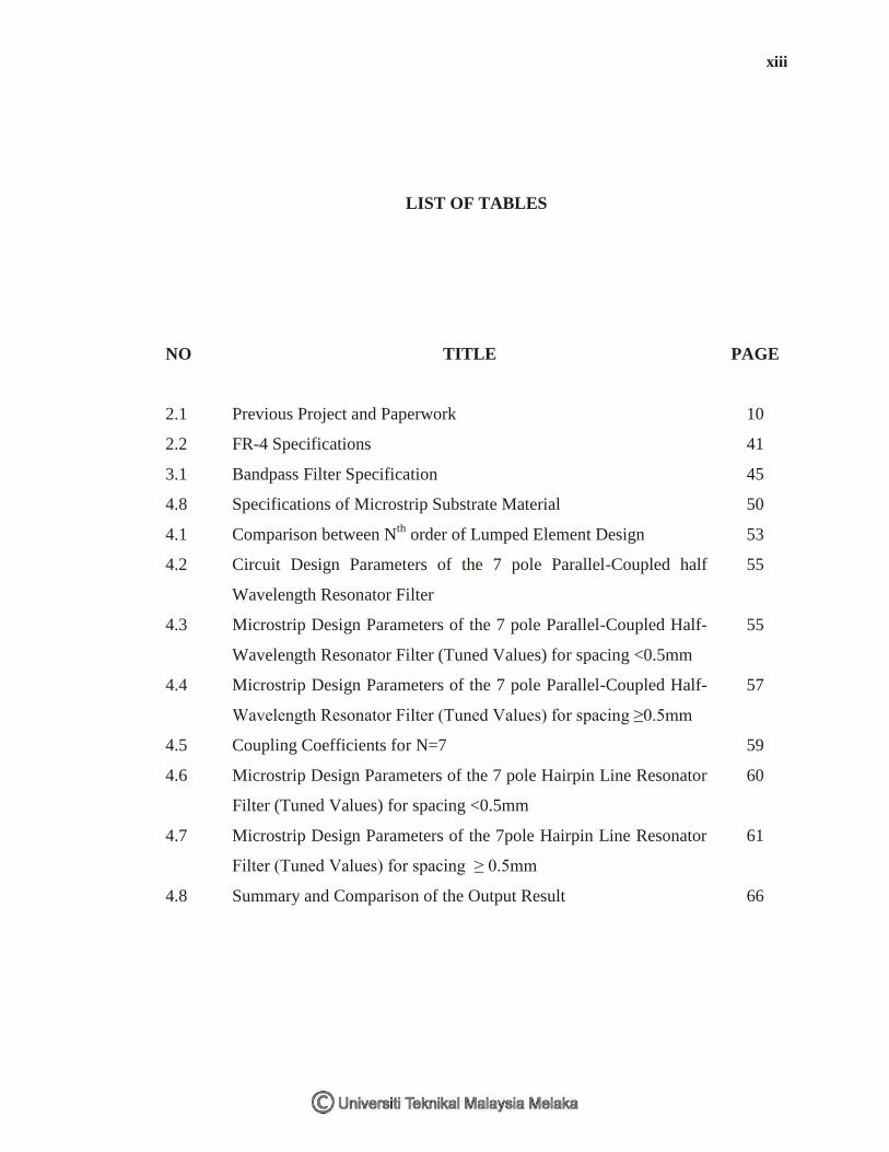
LIST OF TABLES
NO TITLE PAGE
2.1 Previous Project and Paperwork 10
2.2 FR-4 Specifications 41
3.1 Bandpass Filter Specification 45
4.8 Specifications of Microstrip Substrate Material 50
4.1 Comparison between Nth
order of Lumped Element Design 53
4.2 Circuit Design Parameters of the 7 pole Parallel-Coupled half
Wavelength Resonator Filter
55
4.3 Microstrip Design Parameters of the 7 pole Parallel-Coupled Half-
Wavelength Resonator Filter (Tuned Values) for spacing <0.5mm
55
4.4 Microstrip Design Parameters of the 7 pole Parallel-Coupled Half-
Wavelength Resonator Filter (Tuned Values) for spacing ≥0.5mm
57
4.5 Coupling Coefficients for N=7 59
4.6 Microstrip Design Parameters of the 7 pole Hairpin Line Resonator
Filter (Tuned Values) for spacing <0.5mm
60
4.7 Microstrip Design Parameters of the 7pole Hairpin Line Resonator
Filter (Tuned Values) for spacing ≥ 0.5mm
61
4.8 Summary and Comparison of the Output Result 66
xiv
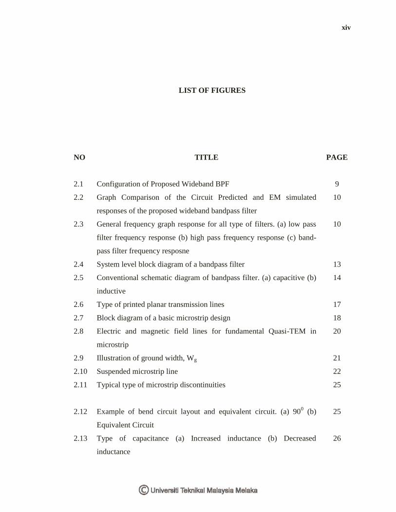
LIST OF FIGURES
NO TITLE PAGE
2.1 Configuration of Proposed Wideband BPF 9
2.2 Graph Comparison of the Circuit Predicted and EM simulated
responses of the proposed wideband bandpass filter
10
2.3 General frequency graph response for all type of filters. (a) low pass
filter frequency response (b) high pass frequency response (c) band-
pass filter frequency resposne
10
2.4 System level block diagram of a bandpass filter 13
2.5 Conventional schematic diagram of bandpass filter. (a) capacitive (b)
inductive
14
2.6 Type of printed planar transmission lines 17
2.7 Block diagram of a basic microstrip design 18
2.8 Electric and magnetic field lines for fundamental Quasi-TEM in
microstrip
20
2.9 Illustration of ground width, Wg 21
2.10 Suspended microstrip line 22
2.11 Typical type of microstrip discontinuities 25
2.12 Example of bend circuit layout and equivalent circuit. (a) 900 (b)
Equivalent Circuit
25
2.13 Type of capacitance (a) Increased inductance (b) Decreased
inductance
26
xv
2.14 Six different configurations for compensated right angled bends 26
2.15 Shows a block diagram of a curving line 27
2.16 Type of open ends (a) Microstrip low pass filter (b) Equivalent circuit 27
2.17 Gap coupling. (a) Microstrip Filter (b) Equivalent Circuit 28
2.18 Step width junction (a) Step in width discontinuity (b) Equivalent
lumped circuit (c) fringing electric field
29
2.19 Tapering technique 29
2.20 Types of T-junction (a) Discontinuity and equivalent circuit (b)
Discontinuity compensation and minimization of the effect
30
2.21 Illustration of cross unction (a) Microstrip notch filter (b)
Discontinuity
30
2.22 High and low impedance short line sections 32
2.23 Type of stubs (a) Open circuited stub (b) Short circuited stub 32
2.24 Type of λg/4 stub 32
2.25 Frequency response of two different impedance stubs 33
2.26 Output of improved DC injection 33
2.27 Lumped resonators (a) lumped element resonator (b) Quasi lumped
element resonator
34
2.28 Distributed Line Resonators (a) Shunt series resonance (b) shunt
parallel resonance
34
2.29 Half wavelength resonator 35
2.30 General structure of parallel coupled microstrip bandpass filter 36
2.31 General layout of tapered hairpin microstrip line bandpass filter 37
3.1 Flowchart of the Project Implementation 43
3.2 Flowchart of Designing The Bandpass Filter 44
3.3 Maximally flat and equal-ripple low-pass filter responses (N = 3). 47
4.1 Lumped Element Design for N=5 52
4.2 S11 and S21 values for N=5 52
4.3 Lumped Element Design for N=9 52
4.4 S11 and S21 values for N=9 53
4.5 The layout for the Parallel Coupled lines Bandpass Filter prototype 55
xvi
4.6 Simulated Graph for Insertion Loss, S21 56
4.7 Simulated Graph for Return Loss, S11 56
4.8 The layout for the Parallel Coupled lines Bandpass Filter prototype 57
4.9 Simulated Graph for Insertion Loss, S21 57
4.10 Simulated Graph for Return Loss, S11 58
4.11 The layout for the Hairpin lines Bandpass Filter prototype 60
4.12 Simulated Graph for Insertion Loss, S21 60
4.13 Simulated Graph for Return Loss, S11 61
4.14 Simulated Graph for Return Loss, S11 62
4.15 Simulated Graph for Insertion Loss, S21 62
4.16 The Fabricated Parallel Coupled Microstrip Line Bandpass Filter 64
4.17 The Fabricated Hairpin Microstrip Line Bandpass Filter 64
4.18 Graph Measured for Insertion Loss, S21 65
4.19 Graph Measured for Return Loss, S11 65
4.20 Graph Measured for Insertion Loss, S21 66
4.21 Graph Measured for Return Loss, S11 66
xvii
LIST OF ABBREVIATION
BPF - Bandpass Filter
CDMA - Code Division Multiple Access
EM - Electro Magnetic
HSDPA - High Speed Downlink Packet Access
HSUPA - High Speed Uplink Packet Access
HD - High Definition
LTE - Long Term Evolution
Q-TEM - Quasi Transverse Electro Magnetic
S-BAND - Frequency range from 2GHz - 4GHz
TEM - Transverse Electro Magnetic
UMTS - Universal Mobile Telecommunication Systems
UWB - Ultra Wideband
VSWR - Voltage Standing Wave Ratio
WiMAX - Wireless interporable Microwave Access
WLAN - Wireless Local Area Network
WMAN - Wireless Metropolitan Area Network
WCDMA - Wideband Code Division Multiple Access
UHF - Ultra High Frequency
SHF - Super High Frequency
DC - Direct Current

xviii
LIST OF SYMBOLS
C - Capacitor
dB - Decibel
f - Frequency
g - Element Values
G - Giga
h - Height
Hz - Hertz
I - Current
L - Inductance
M - Mega
m - Meter
mA - Miliampere
mm - Milimeter
mW - Miliwatt
nm - Nanometer
π - Pi
P - Power
R - Resistance
S - Scattering
V - Voltage
xix
ω - Angular Frequency
Y - Admittance
Z - Impedance
Γ - Reflection Coefficient
δ - Fractional Bandwidth
εr - Relative Dielectric Constant
η - Efficiency
λ - Wavelength
Ω - Ohm
CHAPTER I
INTRODUCTION
This chapter will explain on the project background, objective of project,
problem statement, scope of project, methodology and report structure.
1.1 Project Background
Bandpass filter is an electronic device that are used in both transmitted and
received signals which have to be filtered first at certain center frequency between
two specific frequency (bandwidth) [1]. Bandpass filter is an important component
which must be found in transmitter and receiver. A transmitter or receiver without a
filter will not be able to filter in or out specified wanted frequencies. In the rapid
advancement and developments in wireless telecommunications technology
nowadays, with a major increase in the market demand which intended the
government sector to seek for invention and developments of new applications in
wireless communications.
As what we have discovered in communication these days in, the
development of Worldwide interoperability Microwave Access (WiMAX) and Long
Term Evolution (LTE) in telecommunication services in many countries. They offer
certain features such as the coverage in which customer are supported with minimal
signal of EM waves, high capacity for faster data rate transfer, and the quality of
2
services (QoS) with no error [2]. These are the new applications or systems which
had to be opened to a certain frequency regions in order to provide additional
transmission capacity. But this is not all; there are many more applications like
mobile television which are now widely used in High Definition Television (HDTV)
nowadays, Wireless Local Area Network (WLANs), Bluetooth, and also home based
consumer electronics like cordless phone and microwave oven. With a brief research,
most of this applications uses certain part of frequency region which is located S-
Band frequency region which is frequency ranging from 2GHz to 4GHz to operate.
In realization to this system, a new transmitter and receiver are indeed to be
completed. To design the system, the choice of transmission line technology is
important to provide a good parameters measure for the efficiency of the design.
Microstrip is preferable since the technology of microstrip transmission line is most
extensive used planar transmission line in Radio Frequency (RF) application [1].
Compared to conventional circuit and coaxial lines, printed planar transmission lines
are widely used, having a broadband in frequency, provide compact circuit and light
in weight, and generally economical to produce since they are readily adaptable to
hybrid and monolithic integrated-circuit(IC) fabrication technologies at RF and
microwave frequencies [3].
Apart from that, the primary objective of this project is to design, simulate,
fabricate and analyze the microstrip bandpass filter at S-Band application. The scope
criteria of this project are to study and designing the Microstrip Bandpass Filter at S-
Band application. The filter characterization will be identified and the design will be
test first by simulating it with ADS Simulation Software, then it will be fabricated
using FR-4 as the microstripline substrate material on the printed circuit board (PCB)
and the network design will be tested using network analyser. Lastly the design must
be analyzed and the result must obtained and presented for the insertion loss and
return loss using S-Parameter [2].
The methodology of this project is convenient to be conducted as following
the path to achieve the objective of the project. Literature reviews from journals are
the core method of this project. Later on is the identification of the specification for
the filter as well as to design the filter. After the filter has been designed, it has to be
3
simulated using ADS simulation software and the result will be analyzed using S-
Parameter. Lastly, we will go to the fabrication of the filter and the product would be
tested. The result is expected that the design should be able to obtain insertion loss
and return loss at the most minimum value guided with S-Parameter.
1.2 Problem Statements
The choice of transmission technology is the most prior in this project in
order to provide a perfect parameters result and efficiency towards the bandpass filter
design for a minimal insertion and return loss. In choosing the transmission systems,
one should achieve the following properties which are single mode operation for S-
Band frequency (2-4GHz), and providing low insertion loss and low return loss.
There are many type of transmission line like waveguide which has the advantages of
high power-handling capability and low loss but is bulky and expensive. The other
one is coaxial line which has very high bandwidth and is convenient for test
applications, but is a difficult medium in which to fabricate complex microwave
components [4].
Next one, conventional circuit or lumped circuit which is conceptually helpful
starting point to see how various designs can be realized. But in synthesizing the
circuit in this manner, the implicit symmetries of a lumped circuit element only has a
single mode of propagation and length scales characterizing the element are small
compared to a wavelength which must be respected over the required design band.
Also, the circuit can only be characterized by a single parameter.
In this case, transmission line is realized since it is characterized by two or
more parameters. Such differences in dimensionality between idealized and
physically achievable components in lumped circuit can lead to a breakdown in
applicability of simple circuit based synthesis approaches [5]. In this limit, planar
transmission line models are realized and full wave analysis approaches are required
to simulate the response. Planar transmission lines are divided into four topologies;
Co-Planar Waveguide, Stripline, Slotted line and Microstripline. With a brief study,
4
microstripline is chosen as it fulfills the requirements of the wideband bandpass filter
design which is operating at S-Band (2-4GHz) frequency.
Microstrip is well confined for large line width over substrate height ratios
and is well suited for realizing elements with low characteristic impedance and
radiation loss. Slotline on the other hand has poor field confinement and can be
susceptible to radiative loss. Microstrip filter is preferable since the technology of
microstrip transmission line is most used planar transmission line in Radio
Frequency (RF) application [1]. It is based on printed circuit board (PCB) and offers
easy and cheap in production compared to conventional circuit and coaxial lines [3].
In designing and obtaining the specification of the bandpass filter, a very few
first step have to be carried out to obtain the approximate calculation based on basic
conventional components such as inductors and capacitors. Some problems need to
be identified during the design like what is the maximal loss inside the pass region
and how the filter characteristics should be in transition region. Some strategies are
indeed to be applied in such the choice of waveguide technology which is preferable
in order to obtain the minimal insertion loss [3].
Bandpass filter plays a major significant role in these wireless communication
systems, since the transmitted and received signals need to be filtered as center
frequency with a specific bandwidth. In the realization of widely application uses
part of the frequency at S-Band which brings so much benefit to the mankind. Hence,
this has brought me to design a bandpass filter operating S-Band application using
microstrip.
1.3 Project Objectives
The objective of this project is to design, simulate, fabricate and analyze the
microstrip bandpass filter at S-Band (2GHz-4GHz) application.
5
1.4 Scope of Work
The working scope for this project will cover entirely on bandpass filter
operating at S-Band frequency with the bandwidth of 2 to 4 GHz.
i) Study and designing the Microstrip Bandpass Filter at S-Band application
ii) Identification of the type of microstrip bandpass filter.
iii) Comparing between ideal case design, parallel-coupled line design and
hairpin line design.
iv) Simulating the design using ADS Simulation software .
v) Fabricating the microstripline design using FR-4 as substrate on printed
circuit board (PCB) and test the network of the design using network analyser.
vi) Analyzing comparing the design result for the insertion and return loss with
S-Parameter towards S11 and S21.
1.5 Thesis Outline
Generally, this report consists of 5 chapters which non included with
references and appendices. In chapter 1, the introduction about the project is
presented. The chapter includes brief explanation about the background of the
project, problem statement, objective of the project and the scope of work that is
conducted through out the project.
For the second chapter which is chapter 2, is basically more about literature
review of the paperworks, books and journals that are related to the project. Apart
from that, an explanation about the S-band frequency is stated into this chapter. Also,
a deeper look and review about the theory of microstrip technology is presented in
this chapter.
As in the third chapter, chapter 3 describes about the methodologies that are
applied in this project which are the key step in designing the microstrip bandpass