Release notes for: NCG CAM v13.0 · Release notes for: NCG CAM v13.0.00 Date: 31/01/2014 529 : New...
22
Release notes for: NCG CAM v13.0.00 Date: 31/01/2014 NCG CAM Solutions Ltd are pleased to release NCG CAM v13.0.00 Below are details of the new features and enhancements we have made for v13.0, there are also other little fixes that have been made. Where possible there is a little 'quick guide' to explain the new features. As this is major release, you must use the 'full installer' for v13.0.00 28 : User interface: The maximise icon has been changed to make it more in keeping with normal windows maximise icons. 366 : New feature: It is now possible to cap holes created by a Detect Holes plan. Quick guide: Do a detect hole features (there is no need to create drilling data folders), ensure the Triangulated Surfaces folder and Detect Holes folder are selected / highlighted, pick: Geometry > Cap holes or there is a new button on the toolbar. It is not in the mouse right menu. This will give you a dialog (see right). The 'Cap Method', offers 'Planar' which will work well if the surrounding surfaces are planar, and 'Hole edge' which will work better if the surrounding surfaces are curved, it will work for planar surfaces too. The 'Cap Location' is only available when the Cap Method is Planar, but the holde can be capped at the Top of the hole, Bottom of the hole, or Both.
Transcript of Release notes for: NCG CAM v13.0 · Release notes for: NCG CAM v13.0.00 Date: 31/01/2014 529 : New...

Release notes for:
NCG CAM v13.0.00 Date: 31/01/2014
NCG CAM Solutions Ltd are pleased to release NCG CAM v13.0.00 Below are details of the new features and enhancements we have made for v13.0, there are also other little fixes that have been made. Where possible there is a little 'quick guide' to explain the new features. As this is major release, you must use the 'full installer' for v13.0.00 28 : User interface: The maximise icon has been changed to make it more in keeping with normal windows maximise icons. 366 : New feature: It is now possible to cap holes created by a Detect Holes plan. Quick guide: Do a detect hole features (there is no need to create drilling data folders), ensure the Triangulated Surfaces folder and Detect Holes folder are selected / highlighted, pick: Geometry > Cap holes or there is a new button on the toolbar. It is not in the mouse right menu.
This will give you a dialog (see right). The 'Cap Method', offers 'Planar' which will work well if the surrounding surfaces are planar, and 'Hole edge' which will work better if the surrounding surfaces are curved, it will work for planar surfaces too. The 'Cap Location' is only available when the Cap Method is Planar, but the holde can be capped at the Top of the hole, Bottom of the hole, or Both.

Release notes for:
NCG CAM v13.0.00 Date: 31/01/2014
529 : New feature: It is now possible to edit plans from within the process manager dialog. To use this feature when running a macro or re-running dependent plans, pause the process manager dialog first then run the operation. The plans are paused in the process manager. Select any plan you wish to modify and show its properties, make the modification and choose OK. The plan and its dependents are now updated in the process manager dialog, and originals removed (this is controlled by new option "Cancel orphaned processes" enabled by default). If the re-running of dependent plans also adds unwanted items in the root tree view, removing them there before setting the plans to run will now also remove them from the process manager. This ability to edit plans from within the process manager dialog is disabled in the demonstration version.
530 : New feature: Automation: Added button to the file menu to allow the option to pause macros when running a macro. Quick guide: (covers 529 also)
This is a switch that can be toggled, when enabled there will be a little tick to the left of the option in the menu. If you want to run a macro, but also alter a number of parameters, this will pause the macro so any number of parameters / inputs can be modified, before the macro actually runs.
Now when the macro is actually run (File > Macros > Run), all the boundary, passes, linking operations will appear in the Process manager, they will also be listed in the contents tree. But they will all be 'blocked' or 'queued'.

Release notes for:
NCG CAM v13.0.00 Date: 31/01/2014
It is now possible to expand the contents tree and modify different parameters, cutter diameter, linking order, tool number... This is be done by doing a 'Ctrl + Properties' on an item so the dependant plans may also be run. When the passes, linking or something else has been modified it will be highlighted with the "Modified colour" (user definable in: Tools > Options > System colours). At this moment, although the parameters have been modified, nothing has actually been calculated.
Once all the required changes are made, clicking on the 'Play' button in the Process manager, or clicking mouse right and clicking the 'Pause all' which will be ticked, and will start the recalculation. Once the item has been recalculated it will not be highlighted with the 'Modified colour'.
Documentation updated for new automation feature. 1002 : The Tapping cycle now supports chip break cycle, in the user interface the 'Chip break' option needs to be ticked, then a suitable peck depth defined.
Your machine's control must also support this type of tapping cycle. Documentation updated.

Release notes for:
NCG CAM v13.0.00 Date: 31/01/2014
1312 : New feature: Automation: Boundary independent macros. Added check box to "Save Macro" dialog. If boundary independent is selected, then surface independent is turned on and the check box greyed. If boundary independent is then turned off, the surface independent box becomes live again, but will remain on, so the user will need to check this is what they want. When the user selects a surface and a boundary to run the macro, both items should be in the root of the tree and the surface plan above the boundary plan. Need to update documentation page "Dialog for Saving a Macro" Quick guide: When saving the macro to be boundary independent, the 'Display' needs to be 'No dialogs', then the 'Boundary independent' option can be ticked (this also forces the surface independent to be ticked and greyed out.
To run the macro, the relevant Triangulated surfaces and Boundary must be selected in the contents tree.
File > Macro > Run will now use the Triangulated surfaces and boundary for the creation of the passes / toolpaths in the macro. 1324 : User interface: Added surface comparison to the mouse right context menus. 1339 : Post Processor: The restriction on length of comment lines when using the GPOST post processor has been removed.

Release notes for:
NCG CAM v13.0.00 Date: 31/01/2014
1359 : Rest Finishing: The smoothness of Rest Finishing passes has been improved.
In V11 and v12 (above) it was possible for the Rest finishing passes in the shallow areas to be a little "wobbley", this could cause the machine to slow down.
With the same passes calculated in v13, it is much smoother, resulting on a better tooltpath that is less likely to cause the machine to keep accelerating and decelerating.

Release notes for:
NCG CAM v13.0.00 Date: 31/01/2014
1391 : User interface: Analysis icons (curvature, draft, surface comparison) and new analysis toolbar added. The toggling on and off of curvature analysis has been made consistent with draft and surface comparison functions.
It just makes them more accessible and a little quicker to use. 1679 : Import: Output message improved when reading a Granite file fails, throwing an exception. 1709 : New feature: User interface: Added the ability to pick a surface and remember its colour attribute, then select other surfaces and apply the remembered colour to them. Documentation also updated. Quick guide: With this quick guide the colour attributes for the green surface will be remembered, then applied to the surface for the bottom of all the pockets. Select the triangulated surfaces folder.
Select the surface whose colour attributes are to be remembered. Notice how if you have an item (or multiple items) selected, the folder on the contents tree is highlighted with the select colour.

Release notes for:
NCG CAM v13.0.00 Date: 31/01/2014
From the mouse right menu, pick: Remember Selected Colour
Select the surfaces whose colour is to be modified (the select same colour feature can also be used). Then from the mouse right menu, pick: Set As Remembered Colour
1775 : The Surface Comparison will now allow two 3D stock models to be compared (Note: the performance may be slow). 2015 : Linking: Once we discard a toolpath using the "Minimum Profile Diameter" check we will also discard all lower toolpaths in the same pocket.

Release notes for:
NCG CAM v13.0.00 Date: 31/01/2014
2173 : User interface: A remaining passes folder can now be output for "edit to surfaces", like "edit to toolholder". In both cases creation of the folder is controlled by holding the Ctrl key to show the modifier dialogue, and defaults to true. The 'edited out passes' could then be used with a cutter of the size, but longer body / different tool holder. 2234 : Linking: Performance improvements have been made to improve case of linking passes edited to high resolution stock models. 2248 : Along Curve Passes: XY thickness is now called XY Offset. XY and Z Offsets default to cutter thickness. Cutter thickness is not added on in the background. Documentation updated to match.
2421 : When linking Axially offset pencil passes, there is a new option "prefer order by offset". Selecting this option causes the toolpath to link between adjacent offsets of a given pencil pass, rather than machining all the pencil passes of a given offset before moving onto the next.
2439 : Adaptive Clearance: Change validation of 'Z Max' to prevent a parameterisations which fail in the adaptive clearance. The first step cannot be lower than the surface top minus the safe cut depth if there is a holder defined. 2493 : User interface: A button has been added to the toolbar for the Tool Guide User interface.
This option are still in the menus: View > Tool guide. Documentation updated also,

Release notes for:
NCG CAM v13.0.00 Date: 31/01/2014
2508 : New feature: Five Axis: If the advanced ModuleWorks parameters are displayed, they are now saved and will be retrieved when the plan is run again. The Advanced ModuleWorks parameters are saved whenever the ModuleWorks dialog is invoked, whether or not any changes to any parameters have been made using it. Whenever advanced ModuleWorks parameters are retrieved a plan will be converted to a General five axis plan, eg a Five-axis conversion plan will become a General Five axis conversion plan. 2509 : Boundaries: Converting a curve with arc segments to a boundary with a rotation no longer creates an invalid boundary. 2519 : User interface: A Switch has been added to the Graphics toolbar to enable the swapping of Cutter Tip/Centre without going to the options dialogue, this works in the same way as the Rendering button options.
This saves picking Tools > Options > Graphics and making the change there. 2526 : User interface: The Tool Guide now allows the scroll wheel to increment/decrement the diameter, with a normal, coarse and fine setting using the Ctrl and Shift keys. Scroll wheel = 0.50 increment Ctrl + Scroll wheel = 1.0 increment Shift + Scroll wheel = 0.10 increment Updated the documentation. 2533 : New feature: User interface: The Workplane and Transform Workplane dialogues have been modified by the addition of a toolbar allowing reordering and deletion of selected transformations. This also covers tickets: 1317, 2654 Quick guide:
After defining the required transformations, they can be saved for future use. This is saved in the registry so could be overwritten or cleared (the Clear all button). There is also the option to export the sequence of transformations as a macro (this can obviously be saved with the job). To use a saved transformation, select it from the list, then pick: Load you will see the transformations listed. To use any transformations that were Exported to a macro, click the Load button, then browse and pick the required macro. That will recreate the transformations and the relevant one can be selected.
The stored or saved transformations can be used on the same part or a different part. This will be useful if an original part has been moved around, then you get a new part file with some minor modifications, you want to load the new part then transform it to the same position as you had the original. 2543 : Shaft Profile Analysis: Fixed the Required Body length so it now decreases correctly with decreasing holder clearances. 2556 : Curves: Improved curve extraction and modification, to reduce small steps in closed curves which can then cause loops in the Along Curve Passes
Release notes for:
NCG CAM v13.0.00 Date: 31/01/2014
2576 : User interface: Added the option to display a curves Direction arrows to curves mouse right context menu
2612 : A popup warning message will now be displayed when opening an old (2006 or older) dca file which contains entities that are no longer supported. The message was displayed in the database window previously, and so often got overlooked.
2613 : New feature: Implement a new Helical machining strategy, documentation updated also. As with waterline passes it is aimed more at steep areas than shallow areas, but has the advantage of less linking moves compared to the waterline passes individual Z slices. Quick guide: The basic use is similar to waterline passes, you need to have the Triangulated surfaces and a suitable boundary selected, then "Helical Passes ..." can be selected from the Machining menu, Mouse right menu or the toolbar button:

Release notes for:
NCG CAM v13.0.00 Date: 31/01/2014
The helical passes considers the passes, if the stepover is too wide, it will revert to waterline passes in that area. This can be seen in the image left, the helical passes have been created in the shallow areas. Because of that, and the stepdown defined some passes (shown in red here) have actually been calculated as waterline passes. The cyan passes are helical.
Really the helical passes are another option (to waterline passes) for machiinng the steep areas, but being a helical move there will be minimal linking moves. When defining helical passes, you do need to consider the cutting directions in the passes, the direction of the helix will deteermin climb or conventual milling.
2627 : Tool Database: The interface on the Build Holder page has been improved, to be consistent with other dialogues.
Release notes for:
NCG CAM v13.0.00 Date: 31/01/2014
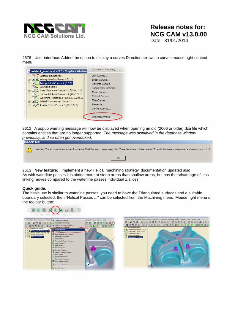
2637 : New feature: The Shaft profile results can now be exported in excel file (CSV) format. The documentation has also been updated for this feature. Quick guide: When creating the passes, define a short cutter and no tool holder. The reason for using the shaft profile, is to create the passes, then find the best cutter body and holder to 'fit'. This allows all the passes to be machined with the most rigid cutter and holder combination. Or even for a special holder to be made.
When defining the passes, the shaft profile also need to be enabled.
Once the pass have been calculated, pick: Toolpath > Shaft profile This can be done after the passes have been linked also.
With the passes (or toolpath) folder selected, pick: File > Export to Excel.
This pops up a simple save as style dialog By default it will use the 'Folder' path from the project settings.

Release notes for:
NCG CAM v13.0.00 Date: 31/01/2014
The filename.csv file which is created can then be read into a spreadsheet program, Microsoft Excel or the open source alternatives, OpenOffice Calc or Libre Calc. It can be opened in a text editor too. The 'listing' is: Diameter , Z Diameter , Z ..... This could then be used to help turn a green-stock arbour or modify a commercial tool holder.
2643 : Linking: Waterline passes when linked using the 'Simplified leads' option, it is now possible to have an overlap to looped passes. Documentation changed to suit. This also fixes ticket 2669.
2645 : Post processor: We now fail the post processing if one or more of the toolpaths is empty. Also fixes ticket 1399. 2646 : Updated the tool sheets to use the current xml namespace. This enables them to be loaded into IE9 and IE10 without problems. You many however need to change some of the default settings for IE9 and IE10 Start IE9 or IE10 (see ticket 2844 for IE11) Pick: Tools (you may need to press Alt to see the menus) > Compatibility View Settings Tick: Display all websites in Compatibility mode 2650 : Five Axis: The Five Axis machining strategies now allow the selection of a points folder to define an origin to be used in the post processor's. 2654 : User interface: Fixed a problem causing English (UK) to display date in American format. 2658 : When loading certain files with the Granite interface, it would sometimes create surfaces which were not visible due to their translucency being set, this has now been fixed. This also fixes ticket 2820 2667 : User interface: When using the 'Export hole data to excel' the dialogs 'browse' option has been made consistent with other dialogs. 2668 : User interface: The Cancel button has now been enabled on the Export detected holes to excel dialogue.

Release notes for:
NCG CAM v13.0.00 Date: 31/01/2014
2670 : Added "Dialogs from boundaries only" option to dialog for saving macros. Macros saved with this option will display dialogs for plans which have a 2D boundary as an input.
2671 : Automation: Provided mechanism to mark modified plans. The colour used to display modified plans is in: Tools > Options > System colours. Plans are marked as modified if they are created after the program has been paused (using global pause). Un-pausing the program then clears all marks. If a macro is started paused, then the plans in the macro are not marked as modified. All plans modified while the macro is paused will be marked.
2689 : Five Axis: It is now possible to use Lollipop cutters in Five Axis machining plans.

Release notes for:
NCG CAM v13.0.00 Date: 31/01/2014
2690 : Tool Database: It is now possible to define Lollipop cutters. The cutter type, Dovetail or Lollipop has to be selected from the drop down list.
These cutter types are only definable within the 5 axis routines.
Documentation updated. 2692 : Five Axis: It is now possible to use Dovetail cutters in Five Axis machining plans. 2694 : Tool Database: It is now possible to define Dovetail cutters. 2697 : Tool Database: The Cutter Design dialogues now have consistent layouts for Advanced parameters.
Release notes for:
NCG CAM v13.0.00 Date: 31/01/2014
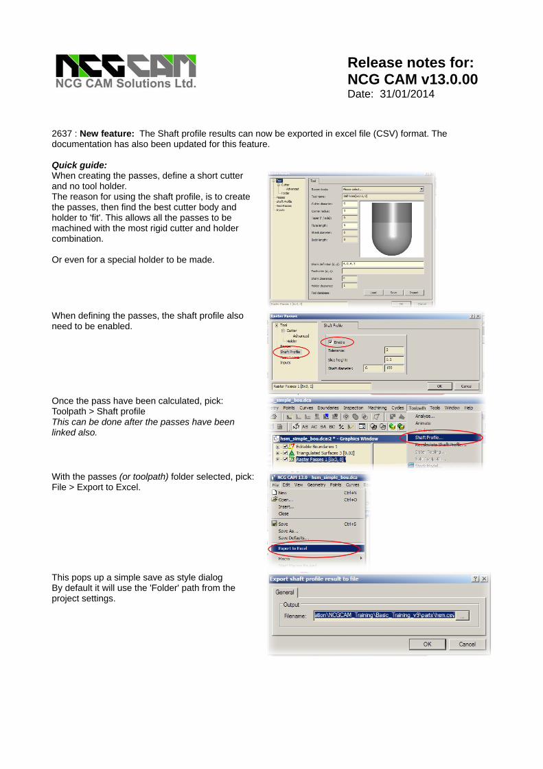
2707 : The 'Extract Slice Curves' now permits extracting multiple Z slices. Upper and lower limits can be set, and how many slices to create. The documentation is also updated.
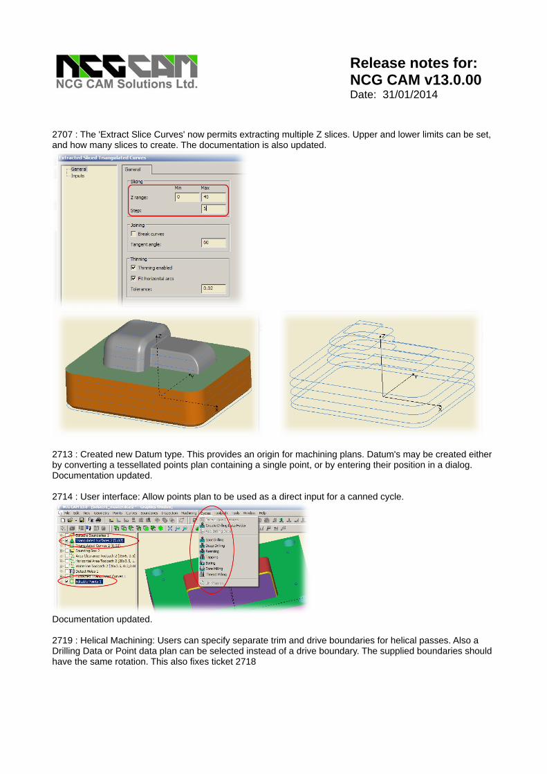
2713 : Created new Datum type. This provides an origin for machining plans. Datum's may be created either by converting a tessellated points plan containing a single point, or by entering their position in a dialog. Documentation updated. 2714 : User interface: Allow points plan to be used as a direct input for a canned cycle.
Documentation updated. 2719 : Helical Machining: Users can specify separate trim and drive boundaries for helical passes. Also a Drilling Data or Point data plan can be selected instead of a drive boundary. The supplied boundaries should have the same rotation. This also fixes ticket 2718

Release notes for:
NCG CAM v13.0.00 Date: 31/01/2014
2734 : Linking axially offset pencil passes, the ramping options are now accessible, this provides the option of disabling profile ramping and 'plunging' onto the pass (the ramp extension allows the cutter to feed onto the part). Documentation updated.
2736 : Geometry: The 'Extract Converted Curves' will now take a Detect Holes folder and create curves for the hole features. This may be useful for milling counter bores for pin heads. Documentation updated. 2744 : Geometry : It is now possible to create a ruled surface between a curve and a point. This could give a solution for capping a none circular hole. Documentation updated. Quick guide: This part has a square hole, the 'top' surfaces is also different surfaces, but you want to machine over the hole.
Select the surfaces for the hole (top surface or sides of the hole), and use the "Extract converted curves" to create a set of curves. Delete the any curves other than those for the top of the hole. Join the remaining curves so it is a single curve. A point will be required at the centre of the hole in XY, and the centre of the curves for the top of the hole in Z. The easiest way to get that position is to select the curves and pick bounding box, then note the Centre positions. There is no need to make the bounding box, it was use as a measuring tool.

Release notes for:
NCG CAM v13.0.00 Date: 31/01/2014
Select the triangulated surfaces, and pick: Points > Create New points folder With the new Points folder selected, pick: Points > Point editor Then enter the XYZ centre points as noted from the bounding box.
Select the curve and point folders, then you can create the rule surface. Although the rule surface is not curved to follow original surfaces, the edges all match up so it can be machined over smoothly.
2745 : The location of the most 'recently used tools' file is now reset when the location of the temporary files folder is changed. If you wish to retain the 'recently used tools' file, close all databases after changing the temp folder and then open a new database. This creates a new MRU*.tdb file in the new location. You can then copy your existing MRU-*.tdb file into that location and use it from then on. Your MRU*.tdb will be: MRU-'login_name'.tdb 2746 : Added option to remove user standard settings. Updated the documentation.
2748 : The 'Export to Excel' options now export as a CSV text format rather than a redundant (Microsoft Workbook) format.

Release notes for:
NCG CAM v13.0.00 Date: 31/01/2014
2749 : Boundaries: Circular boundaries may now be created from drilling data and points folders. Select data and Boundaries > Convert To Boundary. Also fixes #2618
2769 : Geometry : Transforming multiple folders with selected entities no longer gives empty folders. 2771 : Adaptive clearance: Parameterisation changed to allow larger stepovers with ball-nosed cutter. Max stepover removed from the interface. 2772 : Linking: New parameter added to allow users to control angle of linear, cutter compensation approach move. Documentation updated.
2774 : User interface : The text spacing on the Tools > Options > System colour page has been fixed. 2778 : Documentation: Remove dialog image from general page for most linking strategies. 2781 : Adaptive Clearance: Fixed a problem that could cause an error to be thrown if the terrace stepdown was too large, changed step down validations. 2782 : User interface problem fixed, when selecting User Advanced Pages for the 5 axis toolpaths the dialogue tree could get updated incorrectly, this no longer happens. 2785 : The history of a Stock Model now shows the input toolpaths in the order that they were selected when the stock model was created.

Release notes for:
NCG CAM v13.0.00 Date: 31/01/2014
2788 : If a Core Horizontal toolpath is Transformed with Reverse Linking, the new Core Horizontal passes now obey the reverse linking option. 2790 : Improved the performance of the File > Open dialog for Windows 7 and Windows 8 considerably. 2791 : User interface: The contents tree view will now show any folders which have selected entities in them in the select colour.
2792 : Drilling: It is now possible to select a Surface, Point & Datum to create a canned cycle. 2793 : User interface: When drawing a point if a new datum point has been used for machining it no longer fails with an exception. 2795 : User interface: Capitalisation on tool bar tool tips is now consistent. 2798 : User interface : The correct (toolbar options) context menu is now displayed when right mouse is clicked over one of the toolbars.
2800 : Five Axis: There were occasions that allow a five axis toolpath was failing with re-triangulation errors, this has been improved so will happen far less often. 2804 : Drilling: When setting the diameter of the hole for drilling we use the part of the hole we have selected for drilling, not just the highest part. So for a stepped hole, 2.3 dia, with a 5 dia counter bore, the default drill would be 4 dia, but if on the cycle page, if From start of part 2 (the 2.3 dia hole) is set, the default drill diameter is changed to 2.3 automatically. If you define a drill diameter (larger or smaller) then that is not modified. 2805 : Updated the documentation for the Cutting Parameters page to include Core Horizontal Area Passes as input for feedrate optimisation. 2806 : Documentation : Updated the Stock Model page to include Zigzag toolpaths as an input to a 2D stock models. 2809 : User interface: The Label Geometry feature no longer selects the newly created folder. the original folder and entities are left selected. Making: mouse right > invert selection possible.

Release notes for:
NCG CAM v13.0.00 Date: 31/01/2014
2810 : User interface: Improve display for curve extension. A direction arrow is shown so extend start / end is clearer. 2817 : Post Processing: When Post processing the Toolpaths page will allow sorting by thickness.
2818 : Curves: Fixed a potential problem with extending closed curves. 2822 : Machining : It is now possible to use Planar Patch entities in Five Axis & True Surface Machining. This also covers ticket: 2840 2824 : User interface : 2D Stock Model now allows input from split toolpaths and sister tooling 2827 : User interface: It is now possible to use the Control key when invoking a Five Axis machining operation to enable the MW advanced dialogue to be displayed. Documentation undated. 2843 : User interface: When resetting the parameters to their defaults in the bore milling cycle dialogue, the cutter type was not being set correctly, this has been fixed. 2844 : Restored the Mark of the Web (MOTW) comments to specify Local Intranet Zone in the tool sheet files. This will also fix ticket 2816. Please note that in order for tool sheets to be viewed in IE11 it is necessary to change some of the default settings. From within IE11, pick: Tools > Internet Options Go to the "Security" tab, and then pick: Local Intranet Then click on the "Sites" button. "Automatically detect intranet network" needs to be unticked "Include all local (intranet) sites not listed in other zones" needs to be ticked. 2846 : Fixed a problem when rerunning edit to toolholder and resetting system parameters to default. 2849 : User interface: The tool tip for the Shaft Profile plan has been corrected. 2851 : Updated to Parasolid v26.1
2582 : Stock Models: Don't output 'unlinked toolpath' warning message when building stock models from transformed toolpaths.

Release notes for:
NCG CAM v13.0.00 Date: 31/01/2014
2853 : Linking: Pencil passes linking now tries to prevent very small lead out arcs. This behaviour is now the same as waterline and helical machining. 2866 : Import: The construction datum's created for Arc's are now omitted from the Datum Folder when imported. 2870 : User interface: The spelling of "Analyse" in the toolpath pull-down menu has been corrected. 2871 : Documentation: Updated the Geometry Introduction page to include Ruled Surface and Cap Holes. 2872 : Documentation: Moved the Ctrl options help page to more appropriate position in the table of contents. 2875 : Updated the Granite libraries to version 8.0 M090
2863 : Update the "What's New for 13.0.00" Help > Reference topics --> Getting started --> What's New --> What's now in Version 13.0 2874 : Shaft Profile: Fixed problems with required body length / required cylindrical length calculations (With an old dca file, the shaft profile data should be regenerated for full correction). 2888 : Extra checks added to cope with small cutters with negative thicknesses. 2893 : An edit has been made to the Hermel post to support long comments from the Project settings Comments field or toolpaths Cutting parameters comments field. Updated the translations. SolidWorks is a trademark of Dassault Systems. Catia is a trademark of Dassault Systems. Parasolid is a trademark of Siemens GPost is a trademark of Austin NC. Granite, Pro/E, Creo are trademarks of Parametric Technologies Corporation. Windows XP, Vista & Windows 7 are trademarks of Microsoft.