Ansa v13.0.x Release Notes
271
May, 2010 Release Notes v13.0.5
-
Upload
harsh14363 -
Category
Documents
-
view
206 -
download
36
description
Re Note
Transcript of Ansa v13.0.x Release Notes

May, 2010
Release Notes
v13.0.5

BETA CAE Systems S.A.
Kato Scholari, Thessaloniki
GR-575 00 EpanomiGreece
Tel. : +30-2392021420Fax. : +30-2392021417
http://www.beta-cae.gr
Queries & Services : [email protected]
ANSA v13.0.5 Release Notes May, 2010
1. Introduction
This document contains all information about features improvement and problems fixed during development of ANSA from version 13.0.4 to version 13.0.5
ANSA v13.0.5 will ask to load the settings that exist in the “settings folder” of the previous version, i.e. /home/.BETA/ANSA/version_13.0.4 or older v13.0.x) when will start for the first time.
In the /config/ folder of the ANSA installation, there are the following files with user (*.xml) and run-time settings (*.defaults):
ANSA.xml This is the suggested default GUI settings. Load it from the $ANSA_HOME/ANSA.xml
cfd.xml cfd.defaults use the -gui cfd to load the settings and customization for CFD applications
analyst.xml use the -gui analyst to load the customization for pre-processing applications (model set-up), including a User Menu for Safety
TOSCA.xml TOSCA.defaults use the -gui TOSCA to launch the special environment for ANSA-TOSCA applications
radtherm.xml radtherm.defaults Suggested settings for Radtherm users
solid.xml Suggested GUI settings when working (topology/meshing) with Volumes and solid modeling
NOTES:
• ANSA files saved by ANSA v13.0.5 CAN be opened by v13.0.4 and v13.0.3 but cannot be opened by older ANSA versions.
Release History:
v13.0.5 2010.05.12
v13.0.4 2010.03.29
v13.0.3 2009.12.18
v13.0.2 2009.10.01
v13.0.1 2009.05.25
v13.0.0 2008.12.21 ( introductory version )
v12.1.6 2008.12.21
Copyright notes: All other company and product names mentioned in the software and its documentation are property, trademarks or registered trademarks of their respective owners.
BETA CAE Systems S.A. What’s New in v13.0.5 1

ANSA v13.0.5 Release Notes May, 2010
2. What’s new in v13.0.5Enhancements – New Options – New Features
TASK Manager
Barrier Allow the addition of more than one "Barrier contact" items. 19045
SCRIPTING
Impactors definition fields are now editable by scripting.
BETA CAE Systems S.A. What’s New in v13.0.5 2

ANSA v13.0.5 Release Notes May, 2010
3. Known Problems resolved in v13.0.5
GENERAL
Open In v13.0.4 a “fixing operation” was introduced regarding CONS and 3D curves, during OPENing ansa files or CAD data files (step, iges, catia, etc). This operation caused unaccepted delay in opening some ansa files.
A new approach is now introduced which significantly reduces the “opening” time.
19412
Quality criteria Improper writing of quality criteria in files (*.ansa_qual) and ANSA.defaults by v13.0.4 on Windows platforms.
19570
GUI Settings Starting ANSA v13.0.4 for the first time (there was no .BETA or version_13.0.4 folders) on some Windows platforms was failed (only the first time) due to the “Copy settings of the previous version”.
If the folder version_13.0.4 with the ANSA.xml and ANSA.defaults (copied form v13.0.3 for example) was manually created, ANSA v13.0.4 was normally started.
19605
Selection tool When the option “select nodes from elements” (e.g for the function MESH>GRIDs>ALIGN) had been enabled and later a function that need to select “Edges” (MESH>SHELL MESH>RECONS) were activated an abnormal exit occurred.
19553
Output Wave-Front : fixed error that created corrupted ansa files due to renumbering of nodes.
TRANSF. Rotate: starting the operation with '-' gave wrong the results for “Total Rotational Angle”.
19582
CHECK The Pause/Break key stops now the 'checking' operation. 18772
DataBase Browser
Modify Fixed error that caused abnormal exit when using the “command” subif ($,'\:','++')
on Windows 64 bit platforms
19896
The 'if' expression did not work in some cases for defining a variable value in a field, e.g. magnitude for Pressure.
19946
Fixed error regarding calculation of a value given by an 'expression' within a field. e.g. The magn field in DLOAD card of ABAQUS.
15412
15320
BETA CAE Systems S.A. Known problems resolved in v13.0.5 3

ANSA v13.0.5 Release Notes May, 2010
CAD data Translators
Unified Translator
CATIA
Fixed error that caused abnormal exit when ANSA_TRANSL was used that called COMPRESS during a translation session that had no hidden or converted entities.
JTOpen
Fixed error on Windows platforms that caused illegal termination due to memory corruption.
TASK Manager
Include files It was not able to export a read-only include contained in a Task include (e.g. to point to the path where the barrier is located) if it was empty. This is now allowed.
19434
Assembly & Connection Manager
Seam Lines Shells creation failed in rare cases where connection line should be realized by reconstructing the shell mesh with 'single' target edge number.
'Loose Ends' enabled: Adjusting feature line edges to connection curve's limits would not work when feature line was only 1 edge.
18168
TOPO
FACEs DELETE : removing faces that were related to volumes could cause abnormal exit in particular cases.
19909
BETA CAE Systems S.A. Known problems resolved in v13.0.5 4

ANSA v13.0.5 Release Notes May, 2010
BATCH Mesh Manager
The “Triangles percentage” criterion was wrongly caused “Error” quality report although there was not error.
19477
Holes Treatment: in some cases when there was “Target Diameter” value the Zone creation failed.
MESH
ELEMENTs WRAP: Could not rename the part that was created after wrapping. 19408
PENETR. : Freezing the SOLID property of a volume mesh during depenetration would not work; nodes of the solid elements moved.
Volumes LIST : Fixed error that caused abnormal exit when Volumes>Map property list was pressed.
BETA CAE Systems S.A. Known problems resolved in v13.0.5 5

ANSA v13.0.5 Release Notes May, 2010
DECKs
KINEMATICS Automech : fixed error that caused abnormal exit on particular cases. 19562
SETs Fixed error related to CONS that are loaded into a SET. If the selected chain of CONS had segments of different Faces that were “joined” into one Macro area, the nodes of some segments were ignored.
NASTRAN
Input Fixed error that blocked ANSA while reading particular nastran files having DMIG definitions.
19470
D.INFO Corrected mass calculation when the property field "NSM" had a valid value AND a BC set was defined also. The calculation of the total mass took into account twice the NSM (in NET MASS and in NSM mass).
19576
ABAQUS
Fix in reading Abaqus *xxx_TEST_DATA under *MATERIAL contents. The imported *HYPERFOAM was converted to *HYPERELASTIC (if defining BIAXIAL, PLANAR, UNIAXIAL and VOLUMETRIC test data).
(v13.0.4)
19660
LS-DYNA
Property *SECTION_BEAM: Fixed error that caused abnormal exit when editing an SECTION BEAM card with valid IRID definition and changing the ELFORM into 2.
Material Material type 187 (MAT187 MAT_SAMP-1):
Fixed edit card regarding the position of field "LCID_LC" that is moved to correct position.
Now the "LCID_TRI" is visible in the edit card and is not overlapped by "LCID_LC" field.
Output *INCLUDE_TRANSFORM did not offset correctly *ELEMENT_SEATBELT_RETRACTOR and *ELEMENT_SEATBELT_SLIPRING
19721
Input Fixed error that caused unexpected exit when reading Dummy model in combination with *INCLUDE_TRANSFORM
(v13.0.4)
19911
Fixed reading of *DATABASE_CROSS_SECTION_SET regarding the "xSID" sets, which must contain proper type of entities; e.g. between 2 sets with the same ID for "BSID" set, the one that contain beams will be used.
BETA CAE Systems S.A. Known problems resolved in v13.0.5 6
ANSA v13.0.5 Release Notes May, 2010
PAM-CRASH
INPUT CNTAC_/ TYPE 43: XDMP1 field was wrongly read; its value was overwritten by the FSVNL value.
19362
CHECK CONTACTS : when 1D elements (e.g. BEAM) existed in master surface caused abnormal exit.
19797
Dummy When rotating a dummy with pam JOIN elements the information about the angles of the joints were not updated.
19846
CFD decks
STAR CCM
CFX
OpenFOAM
The interior faces lost their orientation. 19697
BETA CAE Systems S.A. Known problems resolved in v13.0.5 7

ANSA v13.0.5 Release Notes May, 2010
MORPH
MODIFICATION FIT > SURF.: The projection of the selected morphing edge was failed on 2nd order Solids.
19609
SCRIPTING
Script function "PickEntities" works now properly when search type is a connection entity. 12042
AssignConnectionSettings : improvements for the the connection attribute strings
The first part (connection type), i.e. AdhesiveLine_ SpotweldPoint_ has to end in “Underscore”. However the rest line with the FE-Repr accepts now lower or upper dash
i.e. SpotweldLine_RBE3_HEXA_RBE3_PSOLID_ID and SpotweldLine_RBE3-HEXA-RBE3_PSOLID_ID are both valid.
Mind that blanks are not allowed.
19548
GetPartDepth script function: Wrong result of Parent and Depth ; it did not return 0 (zero) if no depth was found.
19387
Problem with the foreach session command. The following session did not work:
foreach file ( /home/*.igs ) {OPEN:$fileMESH>SHELL MESH>FREE :}
20043
BETA CAE Systems S.A. Known problems resolved in v13.0.5 8

March, 2010
Release Notes
v13.0.4

BETA CAE Systems S.A.
Kato Scholari, Thessaloniki
GR-575 00 EpanomiGreece
Tel. : +30-2392021420Fax. : +30-2392021417
http://www.beta-cae.gr
Queries & Services : [email protected]

ANSA v13.0.4 Release Notes March, 2010
1. Introduction
This document contains all information about features improvement, new features added and problems fixed during development of ANSA from version 13.0.3 to version 13.0.4.
ANSA v13.0.4 will ask to load the settings that exist in the “settings folder” of the previous version, i.e. /home/.BETA/ANSA/version_13.0.3 or older v13.0.x) when will start for the first time.
In the /config/ folder of the ANSA installation, there are the following files with user (*.xml) and run-time settings (*.defaults):
ANSA.xml This is the suggested default GUI settings. Load it from the $ANSA_HOME/ANSA.xml
cfd.xml cfd.defaults use the -gui cfd to load the settings and customization for CFD applications
analyst.xml use the -gui analyst to load the customization for pre-processing applications (model set-up), including a User Menu for Safety
TOSCA.xml TOSCA.defaults use the -gui TOSCA to launch the special environment for ANSA-TOSCA applications
radtherm.xml radtherm.defaults Suggested settings for Radtherm users
solid.xml Suggested GUI settings when working (topology/meshing) with Volumes and solid modeling
NOTES:
• ANSA files saved by ANSA v13.0.4 CAN be opened by v13.0.3 but cannot be opened by older ANSA versions.
Release History:
v13.0.4 2010.03.29
v13.0.3 2009.12.18
v13.0.2 2009.10.01
v13.0.1 2009.05.25
v13.0.0 2008.12.21 ( introductory version )
v12.1.6 2008.12.21
Copyright notes: All other company and product names mentioned in the software and its documentation are property, trademarks or registered trademarks of their respective owners.
BETA CAE Systems S.A. What’s New in v13.0.4 1

ANSA v13.0.4 Release Notes March, 2010
2. What’s new in v13.0.4Enhancements – New Options – New Features
GENERAL
When launching a new version of ANSA for the first time (starting v1304 and there isn't the .BETA/ANSA/version_13.0.4) user can load the GUI settings from the previous version (if click Yes) or get the suggested from the ANSA installation (by click No).
If there is no older version's “settings folder” and .xml file ANSA automatically starts with the suggested default settings.
Similarly using the -gui option (e.g. ansa1304 -gui cfd) is able to read in the respective settings from the previous version's folder, if exist.
File > Open Read CAD data: IGES, STEP, VDA-FS
The creation of SETs, based on named entities, is now controlled by the new option that is added in Windows>Options>Settings>CAD input topology.
This option affects also the CAD-to-ANSA translation, e.g. CATIA to ANSA
18982
Selections Nodes Selection:
When selecting nodes for a function, a new tool button is available that enables the selection of nodes from entities. This provides the Area selection options.
BETA CAE Systems S.A. What’s New in v13.0.4 2

ANSA v13.0.4 Release Notes March, 2010
Windows > Options
GUI Settings
A new button is added to enable, when it is active, Auto-saving of GUI settings in ANSA.xml file when Quit ANSA.
Shortcuts Modifier key 'Shift' cannot be used for shortcuts any more., e.g. Shift+A. However can be used together with other modifier key, e.g. Alt+Shift+A
Modules > User Menu
It is now allowed to change the Button's custom name of the User menus independently of the custom names you use for their original buttons.
CAD data Translation
JT-Open The extraction of geometry of type "XTB-rep” is now supported. 10872
Data Management
Change Representation : the respective dialog box pops up, even if no DM_Root has been defined, allowing the selection of the default representations: Dont Use/Use/Spc/Lumped Mass/Trim.
BETA CAE Systems S.A. What’s New in v13.0.4 3

ANSA v13.0.4 Release Notes March, 2010
Connection Manager - Assembly
Connectors New search option for Connectors under "Holes": zones = Out
in order to 'grab' only the outer nodes of a zone.
17886
CHECK CONNECTIONS: "Spider positioning" checks the projections of connections and flags an error if they are too close to perimeters or features.
In order to perform the check, the user may specify
- a Diameter of the spider ( if blank, it'll use the connection's Diam - or calculate it using the thickness-to-diameter mapping )
- a Zone width ( blank means zero )
- a Distance from perimeter (blank means zero )
The check will report an error if the distance between a perimeter & the projection is less than (diam + zone + perim_dist)
! Note : this check works only on shells ( meshed macro area and/or FE-mesh).
BETA CAE Systems S.A. What’s New in v13.0.4 4

ANSA v13.0.4 Release Notes March, 2010
MESH – Batch Mesh
SHELL MESH > RECONS: reconstruct on TRIA mesh refines mesh in order to improve quality.
MESH>SHELL MESH> PARAM. > Defeaturing
BatchMesh> Mesh Parameters>Defeaturing>
New parameter “Maintain sharp edge ribs" to handle the sharp edges on ribs, as depicted below:
BETA CAE Systems S.A. What’s New in v13.0.4 5

ANSA v13.0.4 Release Notes March, 2010
SAFETY
Pedestrian - The New 'EU Phase 2' (GTR) regulation is now supported.
- The EuroNCAP v5.0 has been added.
- the 'EC.Reg' renamed to 'EU Phase 1'
BETA CAE Systems S.A. What’s New in v13.0.4 6
ANSA v13.0.4 Release Notes March, 2010
LS-DYNA
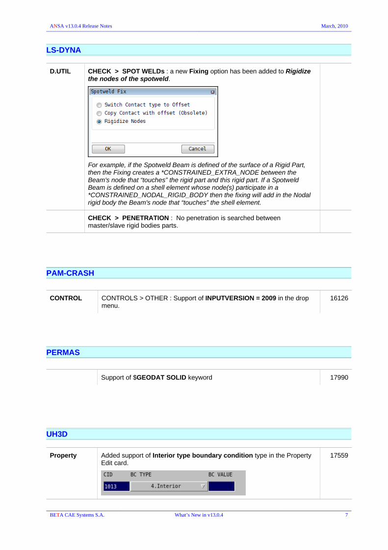
D.UTIL CHECK > SPOT WELDs : a new Fixing option has been added to Rigidize the nodes of the spotweld.
For example, if the Spotweld Beam is defined of the surface of a Rigid Part, then the Fixing creates a *CONSTRAINED_EXTRA_NODE between the Beam's node that “touches” the rigid part and this rigid part. If a Spotweld Beam is defined on a shell element whose node(s) participate in a *CONSTRAINED_NODAL_RIGID_BODY then the fixing will add in the Nodal rigid body the Beam's node that “touches” the shell element.
CHECK > PENETRATION : No penetration is searched between master/slave rigid bodies parts.
PAM-CRASH
CONTROL CONTROLS > OTHER : Support of INPUTVERSION = 2009 in the drop menu.
16126
PERMAS
Support of $GEODAT SOLID keyword 17990
UH3D
Property Added support of Interior type boundary condition type in the Property Edit card.
17559
BETA CAE Systems S.A. What’s New in v13.0.4 7

ANSA v13.0.4 Release Notes March, 2010
MORPH
When moving a Frozen Control point having the MORPHING flag ON a warning message appears informing the user and asking for guidelines.
15001
18886
CONTROLS PARAMS : picking from the screen the control points and highlights the parameter in the list.
19153
BETA CAE Systems S.A. What’s New in v13.0.4 8

ANSA v13.0.4 Release Notes March, 2010
SCRIPTING
New built-in session function:
MESH_SHELL_MESH_RESHAPE_VIOLATING
Added script function "GetSpwDiamFromThickness".
Calculates a diameter value, for a connection point with zero diameter, by Spot Weld Thickness to Diameter Map.
SaveRepresentation() script function. The functions last argument has been enhanced, Accepted values are:
0 : In case current representation is found in DM, the save procedure for the particular part should be skiped.
1 : In case current representation is found in DM, it should be overwriten.
2 : In case current representation is found in DM, a new study version should be created(applies only to parts).
Rigidize new built-in script function
matrix multiplication and DotProduct were changed:
multiplication accepts matrices other than square, and DotProduct vectors with length other than 3
Script collection
ReportConnectionsOfParts :
Reports in csv format the number of connections in which every part/group participates, according to the number of flanges that they connect.
CheckDynaContactsFromSolver :
Reads an LS-DYNA message file that is specified by the user. The following warnings are reported in the Checks List: -Penetrating nodes of sliding contacts -Untied nodes of tied contacts -Nodes of tied contact that will be moved by initialization -Nodes of tied contct that belong to both master and slave sets.
The functions MeasureAngleNodes, MeasureAngleShells, MeasureDistance are removed.
The new built in function CreateMeasurement supports now all kinds of measurements.
BETA CAE Systems S.A. What’s New in v13.0.4 9

ANSA v13.0.4 Release Notes March, 2010
3. Known Problems resolved in v13.0.4
GENERAL
-help works now even if is not the first argument.
Communication with License server
Fixed Retry button in window when communication with License Server is lost.
Fixed error that caused abnormal exit in particular cases. 18314
Fixed error related to improper saving when Volume entities, defined by EXTRUDE>SWEEP, was visible.
Open Property, Material or Set names got lost when the ansa file was opened by ANSA 32bit executable on Windows platforms.
This happened with big ANSA files with size greater than 2Gb.
18608
Input Fixed error that caused illegal termination when importing files with "invalid" parts hierarchy, ie multiple defined hierarchies or invalid link combinations.
Output Wave Front : elements on Macro Area were not exported. Only non-geometry-related elements were exported.
19107
Save Visible as An additional check is now performed to make sure a volume is actually valid for save, in order to avoid saving the entire part instead of only the visible faces.
18214
CAD Output Fixed error that caused abnormal exit in IGES export in particular cases.
v13.0.3
18326
18645
XML reading The reading of XML files (Read Spots, Product information) was not possible on Windows 32bit platforms due to a missing library [libxml2.dll] from the installation.
This particular error has been corrected and the appropriate packages update was done for v13.0.3 on February 3, 2010.
Print to File If "window" was selected or "Grab Ansa" is clicked, transparency got disabled even for png images.
HIDDEN
Q.GRAPH
In Q.GRAPH drawing mode, when ranges were used to display the color bar, if a range was blank, it should not be included in the color bar.
QUALITY CRITERIA
Violation color for quality criteria is now written in ANSA.defaults or ansa_qual files as RGB colors in hexadecimal numbers.
18281
BETA CAE Systems S.A. Known problems resolved in v13.0.4 10

ANSA v13.0.4 Release Notes March, 2010
Wrong calculation of Shells angle criterion for PAM-CRASH 18129
When changing the calculation method for crash time step in F11 in the Shells tab, the Solids tab was not updated.
EL.TEMP
Graph parameters
Fixed error of the contour plot display that did not take all the values into account for UNIQUE COLORS mode.
18868
F11
Presentation parameters
Detail on Demand did not applied on macro areas mesh of ansa files saved by v12.x
17110
TRANSF. Fixed error that caused abnormal exit when Copying>Symmetry a GEB_xx or Connector entity that had a SET as connectivity, and using Set=>None in the Copying parameters window.
Edit cards browsing
Focus problem fixed when opening a referenced entity card by F2 inside edit cards field, e.g. open Material card with F2 in MID field within the Property card.
GUI Settings Menus and Windows > Disable Docking now prevents windows to be “tabbed” as well.
19061
Help window The documentation index could not be accessed, if ANSA was launched typing a relative path.
17962
BETA CAE Systems S.A. Known problems resolved in v13.0.4 11

ANSA v13.0.4 Release Notes March, 2010
Database Browser
Filtering Improper Expression for Names were defined in Filtering ["Filter Rules" that were defined via "Open Card"] in lists where Names contained character(s) (" {}[]:?/()*,\'\"#$!@%%^&+=|<>\t").which were invalid to be saved in the xml.
17988
Modify Correction for the Modification time on ANSA_GROUPs while the Parts Manager was open. The needed time has been now significantly improved.
13173
Fixed error that did not allow color modification (e.g. of properties) using the “modify edit card” by accessing the color pallet with ? in only one of the color fields.
18504
Columns in Lists Fixed errors concerning the values shown in lists for Shells (mainly 2nd order TRIAs).
e.g. the G4 node was not listed (blank was shown) for CTRIA6, wrong ID was shown if the G5 or G6 were added as column.
Save List Header row is now properly "delimiter-separated" on "Save List". When more columns than the default ("Id" and "Name") existed in the list, the default delimiter was added only between "Id" and "Name" in the header row of the exported csv file.
17496
BETA CAE Systems S.A. Known problems resolved in v13.0.4 12

ANSA v13.0.4 Release Notes March, 2010
CAD data Translators
odir <out_dir_name> : the directory in which the (translated) ANSA files will be saved.
Fixed error, for Windows platforms, that caused wrong interpretation of the given 'pathname' and did not allow saving of the ansa files.
UNIFIED Translator
-matvec translation option
Fixed missing information on material vectors when -matvec was used (thickness value and direction) in conjunction with the proper ANSA_TRANSL script function.
This particular error has been corrected and the appropriate executables update was done for v13.0.3 on February 3, 2010.
18039
Catia v4 model file: [ -read_noshow translation option]
Hollow cylinder block was translated as a filled cylinder block.
18012
Fixed error with instantiated parts that contained some types of geometry that was not checked before being added to instances.
Reading of Attributes/Parameters:
The attributes are now always read for parts/PIDs (Bodies), regardless the -read_attr option.
Attributes reading has been fixed for Entities (e.g. curve, points, etc) when the -read_attr translation option was used.
Fixed error that caused abnormal exit when -layer_thic was used together with -notcreate_volumes.
Fix transformation problem in CGR (tessellated data) translation. 18133
JT translator The existing ANSA_TRANSL was not called during the translation. 18342
DATA Management
Check DM updates
Fixed error that reported successful update although the ansa files could not be opened.
17426
BETA CAE Systems S.A. Known problems resolved in v13.0.4 13

ANSA v13.0.4 Release Notes March, 2010
Assembly & Connection Manager
Property referenced by connection elements was removed after applying ERASE FE although was set to "FROZEN DELETE=YES".
17910
Right click is now enabled in ID column of Connection Manager.
Parts viewer Hide/Show/Show Only Parts:
when 'Show Parts' was selected on a multi-instance part, only one instance was shown.
Now, all instances of such a part will show/hide.
Note, that if a part is mentioned by its part id then only this particular instance will be isolated.
Read Spot> VIP
Importing vip spotweld files in databases that contained part instances resulted in setting the connection to just one instance and not the whole module id.
18863
Output > vip2 Fixed error that caused abnormal exit when exporting connections in vip2 (the 2nd or 3rd time) and the 'POINTs' were visible.
18399
Fixed error in the nodes positions of holes opened by FE-Repr. application.
Seamweld Ansa linux 32-bit blocked when applying "Set Weld position" 19050
Hemming The Width field "W" was missing from the hemming edit card. 18659
CHECK CONNECTIONS : blank value fields were wrongly interpreted.
BETA CAE Systems S.A. Known problems resolved in v13.0.4 14
ANSA v13.0.4 Release Notes March, 2010
BATCH Mesh Manager
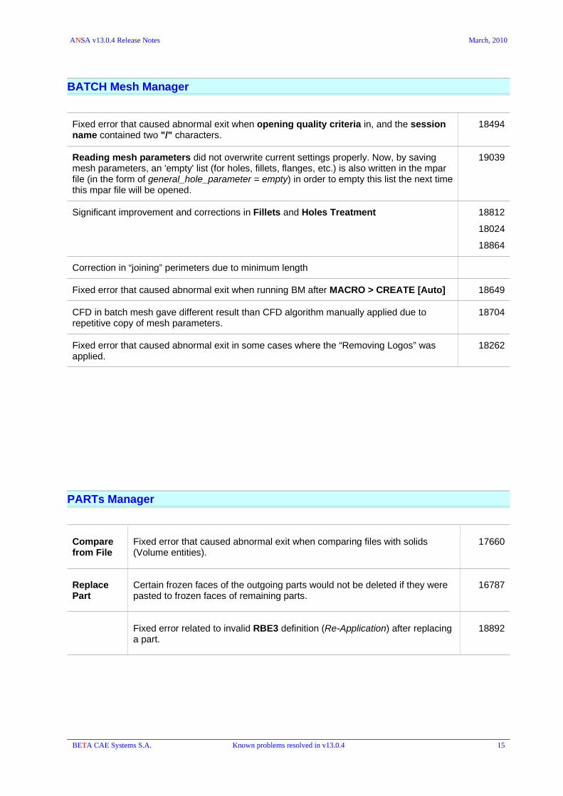
Fixed error that caused abnormal exit when opening quality criteria in, and the session name contained two "/" characters.
18494
Reading mesh parameters did not overwrite current settings properly. Now, by saving mesh parameters, an 'empty' list (for holes, fillets, flanges, etc.) is also written in the mpar file (in the form of general_hole_parameter = empty) in order to empty this list the next time this mpar file will be opened.
19039
Significant improvement and corrections in Fillets and Holes Treatment 18812
18024
18864
Correction in “joining” perimeters due to minimum length
Fixed error that caused abnormal exit when running BM after MACRO > CREATE [Auto] 18649
CFD in batch mesh gave different result than CFD algorithm manually applied due to repetitive copy of mesh parameters.
18704
Fixed error that caused abnormal exit in some cases where the “Removing Logos” was applied.
18262
PARTs Manager
Compare from File
Fixed error that caused abnormal exit when comparing files with solids (Volume entities).
17660
Replace Part
Certain frozen faces of the outgoing parts would not be deleted if they were pasted to frozen faces of remaining parts.
16787
Fixed error related to invalid RBE3 definition (Re-Application) after replacing a part.
18892
BETA CAE Systems S.A. Known problems resolved in v13.0.4 15

ANSA v13.0.4 Release Notes March, 2010
TOPO
CONS PASTE: Correction of the “multi” paste of CONS.
Now the selected CONS are recognized as two chains and the pasting is done without problems. Generally, the selected CONS are split to independent chains if the angle between consecutive CONS is less than 30 degrees, instead of 60 degrees that was used.
17958
WORK PLANEs
INFO : reported wrong coordinates for origin for the non-default working planes.
17935
FACEs RM.DBL >Geometry : editing results.
Corrections in Faces picking after editing the results (remove/add) while in function or later by other function, e.g. Focus group..
18152
SKIN : fixed wrong thickness calculation and wrong offset direction. 19047
BETA CAE Systems S.A. Known problems resolved in v13.0.4 16

ANSA v13.0.4 Release Notes March, 2010
MESH
Quality criteria Improve mesh distortion criterion result. Correct problem detect and color elements in areas with joined macro area's perimeters.
17888
Q.GRAPH When using ranges to display the color bar, if a range was blank, it should not be included in the color bar.
MACROs SET PID : fixed instability errors (and abnormal exit) when the “Multi Property” option was used (with multiple properties selected in the list to be applied onto selected Macro areas).
18335
PERIMETERs
MACROs
LENGTH : both functions use now minimum and maximum values of length of the selected items and not the first one.
16706
PERIMETERs
MACROs
SHELL MESH
JOIN [Keeping Mesh] : fixed error that caused instability.After applying this function and then using one the following caused abnormal exit.
MACROs>RELEASESHELL MESH>SMOOTHSHELL MESH>RECONS
18799
18800
SHELL MESH RECONS : failed to identify holes when a triple bound is included in the selection.
18174
RECONS : fixed error that caused unexpected exit when function was applied on 2nd order mesh and a hole's zone edge was attached to a “joined” macro area perimeter.
18236
RESHAPE: fixed error that caused abnormal exit when applied on 2nd order shells that were selected from a macro area Without selecting all the macro area shells.Therefore the Violating option on 2nd order shell mesh (on Macro Areas) led to illegal termination.
SUPPRESS: Feature line angle limit specified within the function should not overwrite the Mesh parameters given in SHELL MESH>PARAM.
18267
SMOOTH : fixed error that caused abnormal exit when applying to FE 2nd order shell sharing the 1st order nodes with shells of Macro Area.
FILL > Gap (Coons) : assigns now the created shells to the “Current” PID if it is defined.
FILL > Hole : failed to performed in case of Visible Triple bounds, even if the hole's boundary was selected. If the Triple bounds were not displayed the function worked well.
18077
COLLAPSE : fixed error that caused unexpected exit. 19108
FEMTOPO : fixed error for cases where fem-topo is performed for very small boundary edges.
17150
BETA CAE Systems S.A. Known problems resolved in v13.0.4 17

ANSA v13.0.4 Release Notes March, 2010
ELEMENTs WRAP>Variable Length: correction of the result regarding “gaps' to wrap and minimum element length achieved.
18030
INFO : Correction of the report for the "crash time step" calculation deck for solid elements.(1st/2nd order). The calculation for the shell elements was reported instead).
PENETR. > ELEMENT LENGTH : Growth rate improvement in rare cases would lead to unexpected exit.
(32-bit executable, v13.0.3).
PENETR. > USER THICKNESS: Fix wrong edge-2-edge de-penetration that did not allow auto-fix of penetrations.
OFFSET > Move : correct error that caused unaccepted result if the function was repeated on the same selection.
18858
VOLUMEs MAP : major corrections and results improvement. Several errors have been fixed.
18401
18199
17128
MAP: If the map volume mesh is created with straight transition between the two faces, since the upper is a linked face, Ansa always reported, that the master and the slave macro areaswere not compatible.
If the linked macro was selected at first, map worked.
16815
MAP : fixed error that caused abnormal exit when Map was applied to 2nd order mesh.
18596
LAYERS : the “Layer Area” window has been changed (improved) in order to avoid bad performance in case of big number of listed Properties.
BETA CAE Systems S.A. Known problems resolved in v13.0.4 18

ANSA v13.0.4 Release Notes March, 2010
DECKs
Database Browser
Clicking on a SET content (through SETs window), clicking "Go back" and then "Go forward" resulted in wrong columns being showed.
Material Database
READ DB : Fixed error that caused abnormal exit when reading Material Databases that contained ANSA comment keywords of ANSA geometric entities, e.g. SpotweldConnection
NODEs / GRIDs
EXPLODE : On Windows OS platforms in case of more than 1000 nodes to be ”exploded” causing abnormal exit.
18822
ALIGN : when selecting “Nodes of elements” solid elements (and Thick shells) were selected instead of their Facets.
ELEMENTs INFO : Correction of the report for the "crash time step" calculation deck for solid elements.(1st/2nd order). The calculation for the shell elements was reported instead).
BOLT Body type = 'SOLID' , the combobox 'Number of Hexas' had two times the value 4, instead of : 4-8-16
SET Fixed error that caused unexpected exit when defining a SET with SOLIDFACETs via Database Browser (drag'n'drop).
18455
D.UTIL D.INFO : Fixed error that caused abnormal exit on Windows XP 32 bit. 19097
CHECK > Penetration: Fixed error, causing wrong de-penetration, when de-penetrating 3D-elements vs non-3D-elements in LS_DYNA, ABAQUS, ANSYS.
RENUMBER> [Offset]: fixed errors in interface (OK or Enter were interpreted as Cancel) and errors that might cause “Corrupted ansa files” when “FROZEN IDs FOUND...” and Cancel was clicked.
S A F E T Y
Coordinate systems defined with vectors did not move through kinematics tool or dummy articulation.
Seatbelt: Fixed error that blocked ANSA when generating Seatbelt Elements that were about to be placed into a new Part but were not (The Part Manager was closed instead).
19098
BETA CAE Systems S.A. Known problems resolved in v13.0.4 19
ANSA v13.0.4 Release Notes March, 2010
NASTRAN
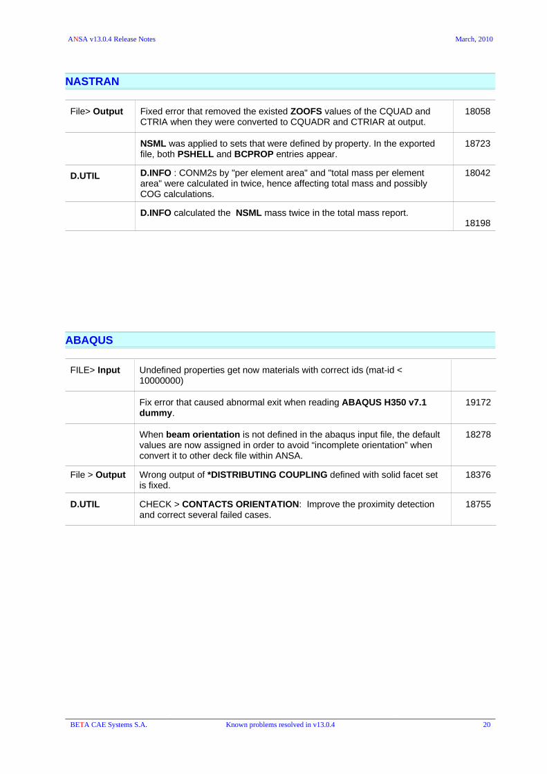
File> Output Fixed error that removed the existed ZOOFS values of the CQUAD and CTRIA when they were converted to CQUADR and CTRIAR at output.
18058
NSML was applied to sets that were defined by property. In the exported file, both PSHELL and BCPROP entries appear.
18723
D.UTIL D.INFO : CONM2s by "per element area" and "total mass per element area" were calculated in twice, hence affecting total mass and possibly COG calculations.
18042
D.INFO calculated the NSML mass twice in the total mass report.18198
ABAQUS
FILE> Input Undefined properties get now materials with correct ids (mat-id < 10000000)
Fix error that caused abnormal exit when reading ABAQUS H350 v7.1 dummy.
19172
When beam orientation is not defined in the abaqus input file, the default values are now assigned in order to avoid “incomplete orientation” when convert it to other deck file within ANSA.
18278
File > Output Wrong output of *DISTRIBUTING COUPLING defined with solid facet set is fixed.
18376
D.UTIL CHECK > CONTACTS ORIENTATION: Improve the proximity detection and correct several failed cases.
18755
BETA CAE Systems S.A. Known problems resolved in v13.0.4 20

ANSA v13.0.4 Release Notes March, 2010
LS-DYNA
Input Correction on reading the initial angle of the joints in latest FTSS dummies (v7.1) that has a new definition.
18589
Fixed error when reading twice an Ls-Dyna input file that contained *INITIAL_AXIAL_FORCE_BEAM with "sets"= "keep-old". The second keyword did not read in.
When importing a file with *DATABASE_CROSS_SECTION_PLANE the "PSID" should be a set that contains only parts. In case 2 sets with the same ID are imported the Set that contains parts will be used as PSID, following exactly the LS-DYNA rules.
Fixed error that caused abnormal exit when importing *INCLUDE TRANSFORM with OFFSET ID and *MAT_ADD_EROSION has to be offset.
19180
Output *DATABASE EXTENT BINARY : the values given in fields NINTSLD, NEIPH of the respective card, were wrongly interpreted in the exported dyna file on IBM-AIX operating system.
On HP-UX platforms an error caused abnormal exit at opening/closing the DATABASE EXTENT BINARY card.
18156
CONTACT : in case the MSTYP and/or SSTYP was type=Part_Set and is defined by Elements and/or Faces then it was exported “empty”. This is fixed and now the PART of the included Elements/Faces is written in the *SET_PART_LIST that is exported.
Moreover, the drawing of the Contact complies to the “Part_Set” type and the entire PART is highlighted (as it is about to be exported).
19044
The SHRF value for BEAM in ANSA.defaults was not taken into account; the TSHELL value was taken instead.
18216
Elements
Transformations
*Element_Mass - *Element_Inertia: the Inertia values were not get transformed (updated) due to transformations (e.g. by the Geometry>TRANSF. function) if they where defined in the global coordinate system.
BOUNDARY Fixed errors related to *BOUNDARY_PRESCIBED_MOTION handling:
– The Reference on a node that was used as “orientation node” for relative displacement of a *BOUNDARY PRESCIBED MOTION, did not report the boundary entity.
– it was not allowed to PASTE a 'free' node that was used as “orientation node” for relative displacement to another node. This should update the *Boundary card with the new node id..
– it was not allowed to define a *BOUNDARY PRESCIBED MOTION with VAD=4, relative displacement, without the “optional orientation nodes” (NODE1 – NODE2).
18268
MATDB Unnecessary ANSA Comments written out when saving a MATDB caused ANSA to exit when the Material Database was read back into ANSA.
18064
Materials It was NOT allowed to assign MAT 77 to a *SECTION_SHELL within ANSA.
18664
BETA CAE Systems S.A. Known problems resolved in v13.0.4 21
ANSA v13.0.4 Release Notes March, 2010
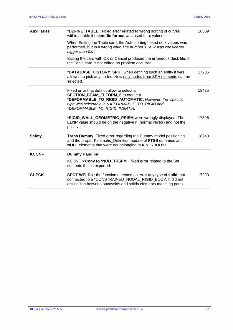
Auxiliaries *DEFINE_TABLE : Fixed error related to wrong sorting of curves within a table if scientific format was used for x values.
When Editing the Table card, the Auto sorting based on x values was performed, but in a wrong way: The number 1.6E-7 was considered bigger than 0.04.
Exiting the card with OK or Cancel produced the erroneous deck file. If the Table card is not edited no problem occurred.
18309
*DATABASE_HISTORY_SPH : when defining such an entity it was allowed to pick any nodes. Now only nodes from SPH elements can be selected.
17285
Fixed error that did not allow to select a SECTION_BEAM_ELFORM_6 to create a *DEFORMABLE_TO_RIGID_AUTOMATIC. However, the specific type was selectable in *DEFORMABLE_TO_RIGID and *DEFORMABLE_TO_RIGID_INERTIA.
18475
*RIGID_WALL_GEOMETRIC_PRISM were wrongly displayed. The LENP value should be on the negative n (normal vector) and not the positive.
17896
Safety Trans Dummy: Fixed error regarding the Dummy model positioning and the proper Kinematic_Definition update of FTSS dummies and NULL elements that were not belonging to KIN_RBODYs.
18240
KCONF Dummy Handling
KCONF >'Conv to *NOD_TRSFM' : fixed error related to the Set contents that is exported.
CHECK SPOT WELDs : the function detected as error any type of solid that connected to a *CONSTRAINED_NODAL_RIGID_BODY. It did not distinguish between spotwelds and solids elements modeling parts.
17290
BETA CAE Systems S.A. Known problems resolved in v13.0.4 22

ANSA v13.0.4 Release Notes March, 2010
PAM-CRASH
Mesh Quality Wrong calculation of angle criterion for PAM-CRASH is fixed. 18129
TRANSF. Copy: :Error while copying FRAME IAXIS 0; the new Frame had IAXIS =1. 18157
Output If an RBODY was put in the Set then in the exported GROUP_/_ its ID was referenced as ELE. This is fixed and now the nodes of the Rbody are written withi the GROUP.
18397
RADIOSS
File > Input Fixed error related to Radioss files having /SUBSET keywords on IBM AIX 5.2 RELEASE version.
File > Output
Fixed error regarding the material card update according to CONTROL>ACTIVE VERSION.
When switching from CONTROL the ACTIVE VERSION (e.g. from v4.1 to v5.1 and vice versa), the Material Card was not updated. Specifically, in LAW36 Material Card, the 2 fields (Ipfun and Fscale) were always displayed although they shouldn't.
17099
D.UTIL CHECK > CONTACTS : When shells and solids had common nodes , the 'facet thickness' of the solids was not calculated correctly.
17676
BETA CAE Systems S.A. Known problems resolved in v13.0.4 23

ANSA v13.0.4 Release Notes March, 2010
PERMAS
Output Fixed Beam Element orientation.
Fluid Element type should be exported as FLPENTxx and not FLPNT
Shell element type SOLID_SHELL should not take NSM.
Fixed error in the area calculation for beam integrated sections.
D.UTIL D.INFO: Corrections in Mass calculation
MEDINA
Input Correction of the CBUSH element orientation system.
Output Correct the Contact's Master and Slave Set Ids.
PBEAM Cross Section information complies now to Medina definition.
Correction of the interpretation of CBUSH definition.
Input / Output
The pids of non-realized spotwelds were ignored during import/Export of medina files
15437
BETA CAE Systems S.A. Known problems resolved in v13.0.4 24

ANSA v13.0.4 Release Notes March, 2010
STAR CD / STAR CCM
File > Output Fixed STAR CCM output baffles.
STAR-CD output: fixed warning message that was printed in case material ids were equal to or grater than 1000.
17247
CFX
File > Output Output in CFX format caused random orientation of elements on baffle surfaces.
18807
BETA CAE Systems S.A. Known problems resolved in v13.0.4 25

ANSA v13.0.4 Release Notes March, 2010
MORPH
BOXES Correction of LOAD > VISIBLE in 2D Boxes. 18014
2DMORPH > Curves : improved performance on the creation of 2D-Morph Boxes based on CONS (macro area perimeters)
18604
CONTROLS PARAMS : fixed error that caused abnormal exit at definition of Scale parameter.
18463
NESTED > New: there was no auto-creation of the REFGRID (at the cog of the nested element).
18474
MODIFICATION EXTEND : fixed error that caused unaccepted results. 18076
CROSS SECTION
TOPO>CROSS SECTION> Cut: in case a Cross Section was defined by “cutting” on FE - Model and Geometry the Cross Section was generated only on the FE.
17926
BETA CAE Systems S.A. Known problems resolved in v13.0.4 26

ANSA v13.0.4 Release Notes March, 2010
SCRIPTING
CreateEntity, CreateEntityVa: When called for NASTRAN Bc's (force, spc, etc,) for a deck other than NASTRAN (e.g. PERMAS $CONLOAD) caused abnormal exit.
PositionPedestrian : In case the XZ plane of the headform did not coincide with the global XZ, although the headform was correctly positioned, the rotational components of the transformation calculated were wrong.
11204
PickNodes : fixed the wrong return of PickNodes function after picking nodes on perimeters/Faces.
18611
AddPartToMeshingScenario : The first item sent to script function failed to be added if it was a property.
Also, the function returns now 0 if the item is not added to the scenario.
18628
ChangeElemType : fixed error that caused abnormal exit when used to convert CONSTRAINED_NODAL_RIGID_BODY to CONSTRAINED_INTERPOLATION.
18687
PrintToFileVa : when executing the function for the first time, it worked OK. However, If executing the function for a second time, ANSA saved the image of whatever the monitor displays at that moment (and not of the ANSA graphics window).
18750
VolumesDetect : the function now returns 0 if no volumes are detected and N for the N number of volumes detected.
17781
D.INFO: correction of the image generation that was not the visible model. 18049
BETA CAE Systems S.A. Known problems resolved in v13.0.4 27

December, 2009
Release Notes
v13.0.3

BETA CAE Systems S.A.
Kato Scholari, Thessaloniki
GR-575 00 EpanomiGreece
Tel. : +30-2392021420Fax. : +30-2392021417
http://www.beta-cae.gr
Queries & Services : [email protected]

ANSA v13.0.3 Release Notes December, 2009
1. Introduction
This document contains all information about features improvement, new features added and problems fixed during development of ANSA from version 13.0.2 to version 13.0.3.
In the /config folder there are the following files with user (*.xml) and run-time settings (*.defaults):
ANSA.xml the first time you launch ansa_v13.0.3 this ANSA.xml will be loaded
cfd.xml cfd.defaults use the -gui cfd to load the settings and customization for CFD applications
analyst.xml use the -gui analyst to load the customization for pre-processing applications (model set-up), including a User Menu for Safety
TOSCA.xml TOSCA.defaults use the -gui TOSCA to launch the special environment for ANSA-TOSCA applications
radtherm.xml radtherm.defaults Suggested settings for Radtherm users
solid.xml Suggested GUI settings when working (topology/meshing) with Volumes and solid modeling
NOTES:
• ANSA files saved by ANSA v13.0.3 cannot be opened by older ANSA versions.
• A new directory is created “tutorials_and_examples” with data that have been extracted from the “docs” directory. The “optimization_examples” folder is now placed in the examples sub-directory. Mind to download the extra file ansa_v13.0.3_tutorials_and_examples** that contains now the tutorials and examples.
• Updated / New documents
•Updated CFD Practices documentation
•Enhanced Script Collection
•New Tutorials:
Batch Mesh (./tutorials_and_examples/tutorials/TOPO_MESH/batch_mesh/)
Release History:
v13.0.3 2009.12.17v13.0.2 2009.10.01
v13.0.1 2009.05.25
v13.0.0 2008.12.21 ( introductory version )
v12.1.6 2008.12.21
Copyright notes: All other company and product names mentioned in the software and its documentation are property, trademarks or registered trademarks of their respective owners.
BETA CAE Systems S.A. What’s New in v13.0.3 1
ANSA v13.0.3 Release Notes December, 2009
2. What’s new in v13.0.3Enhancements – New Options – New Features
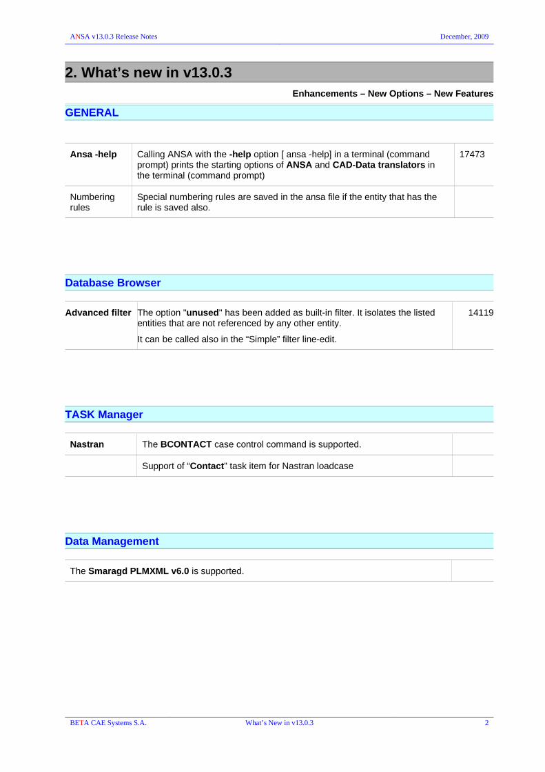
GENERAL
Ansa -help Calling ANSA with the -help option [ ansa -help] in a terminal (command prompt) prints the starting options of ANSA and CAD-Data translators in the terminal (command prompt)
17473
Numbering rules
Special numbering rules are saved in the ansa file if the entity that has the rule is saved also.
Database Browser
Advanced filter The option "unused" has been added as built-in filter. It isolates the listed entities that are not referenced by any other entity.
It can be called also in the “Simple” filter line-edit.
14119
TASK Manager
Nastran The BCONTACT case control command is supported.
Support of “Contact” task item for Nastran loadcase
Data Management
The Smaragd PLMXML v6.0 is supported.
BETA CAE Systems S.A. What’s New in v13.0.3 2

ANSA v13.0.3 Release Notes December, 2009
Connection Manager
File>Output
ANSA_Comments
The “Comment” and “Name” attributes of the Connections, as they appear in the respective columns of the Connection manger, are exported as ANSA_COMMENT.
14995
Seamweld For the FE-Representations:
RBE2, RBE2-CBEAM, RBAR-SHELL, NASTRAN CWELD, Y-JOINT-SHELL, OVERLAP-SHELL, EDGE-WELD-SHELL, Y-JOINT-FEMFAT, OVERLAP-FEMFAT, EDGE-WELD-FEMFAT
the check box “Loose Ends” has been added.
When it is "ON" , there will be no split in the mesh to make it match the connection line.
FE-Representations: RBE2 , RBE2-CBEAM , RBE3
When a cut is performed ( or elements split , when the new 'Loose Ends' flag is off ) , it is followed by a local mesh reconstruction.
BETA CAE Systems S.A. What’s New in v13.0.3 3

ANSA v13.0.3 Release Notes December, 2009
MESH
VOLUMEs MESHV > DELAUNAY: The function takes into account the Size boxes.
MESHV > DELAUNAY: Improvements to avoid swaps on boundary for better quality.
The Delaunay volume mesh takes into account the Size boxes.
Batch Mesh
All Mesh Parameters are now converted according to the current UNITS (Windows>Options>Settings>Units)
– When changing the units all parameters that are distances will be converted according to the new units ( global mesh, volume and layer parameters).
– Read parameters (ansa defaults, *.mpar, *.lpar): reading distance values are supposed to be in [mm], so conversion is done if the current units in ANSA are not [mm].
– Saving parameters : all distance values are saved in [mm], regardless the current selected units in ANSA.
!!! Mind to check the “Scale Model dimensions” in order to comply the changes between 'mesh parameters / criteria values' with the 'model's size'.
BETA CAE Systems S.A. What’s New in v13.0.3 4

ANSA v13.0.3 Release Notes December, 2009
ABAQUS
ELEMENTs Support of C3D10I element type of Abaqus v6.9 16245
LS-DYNA
D.UTIL CHECK > CONTACTS
When nodes take thickness from the minimum element length rule, they are shown in a sub-item of the check>contact header.
17653
FLUENT
File > Input Changing of Input option labels of options :
Skip Inner Faces → Skip Interior Type Faces
Skip Cells → Skip Volume Mesh
MORPH
BOXES 2DMOPRH > CONV2BOX
The converted Boxes are split in the middle.
17339
2DMOPRH > CONV2BOX
User is asked to Keep or Delete the original 2D Boxes.
17340
MODIFICATION MOVE & DIRECT: middle-mouse functionality of confirmation window is changed in order to be the same with the other modification functions. Now the middle mouse click Cancels the movement.
BETA CAE Systems S.A. What’s New in v13.0.3 5

ANSA v13.0.3 Release Notes December, 2009
SCRIPTING
CurvesConnectMulti: New built-in script function. Connect multiple curves. It takes a matrix of CURVES with the total of matrix and tolerance (nodes matching distance) and the angle between the curves.
GetPartCogAndPrincipalInertiaVectors : New built-in script function. It calculates the part's center of gravity, based on the part's faces, shells, solids and volumes. It also calculates the principal inertia vectors.
Session Command:
OUTPUT_PAMCRASH: added an extra argument : output_rmat = "on", "off"
KinematicsSetParameters : Support move by actuator joint in scripting 17415
BrachEntity : supports now the creation and modification of PASTED_NODES.
CreateMeasurement : new built-in script function
BETA CAE Systems S.A. What’s New in v13.0.3 6

ANSA v13.0.3 Release Notes December, 2009
Script collection
ShellSet2FacetS
Select from a list, sets with faces or shells. In the case that there are solids elements connected to these faces/shells, ANSA will add or create a new set (depending on flag) with the facets of these elements.
TriasWithCommonEdge
Finds trias with common edge
ParseDirectoryTree
Searches recursively in directory for finding files of specific type
SelectionAssistantConnectorsGEBs
Generates the button "SelAssistantCntrGeb"in the User Script Buttons menu, under the custom category "AUXILIARIES".This function popsup a custom user interface. The user is prompted to selected the entity types whose visibility he/she needs to control. Available entity types are: Connectors, GEB_BC, GEB_OR and GEB_MT. The visibility of the entities is controlled based on the entities that are currently visible on the screen. These entities can either be generated by the Connectors/GEBs or be the entities the Connectors/GEBs attach to (i.e. connectivity). The options available in the dropdown are :
Visible Ents: This will control the visibility of all those Connectors/GEBs whose generated entities are currently visible.
Visible Parts Visible Props: These two options will control the visibility of all those Connectors/GEBs that reference even one of the visible parts or properties in their connectivity fields. This does not work with ANSAGROUPs.
Visible Parts Only Visible Props Only: These two options will control the visibility of all those Connectors/GEBs for whom all the connectivity parts or props are currently visible.
Visible Parts/Props Visible Parts/Props Only: These options allow the visibility control of all those Connectors/GEBs that have "mixed" connectivity, consisting of both parts and props.The visibility control performed by the buttons located at the bottom of the window: Show, Hide, Show Only.
BringConnectivityToVisible
Generates the button "AND_Connectivity" in the User Script Buttons menu, under the custom category "AUXILIARIES". This function gets the user in selection mode, in order to select any number of Connectors/GEB_xx or Connection Entities. On middle click it brings to visible their connectivity parts/props/includes.
The function "FourBars.bs" is removed.
BETA CAE Systems S.A. What’s New in v13.0.3 7

ANSA v13.0.3 Release Notes December, 2009
3. Known Problems resolved in v13.0.3
GENERAL
ANSA -h The -h option is used only for : -h port@server,
Use license server "server" on port "port"
The Help with the available options is printed now only with the “-help” option.
File>Compress Fixed error that caused major instability when “compressing” CROSS SECTION Curves.
Window configuration, e.g. Active buttons, options, etc, are now saved in the ANSA.xml as soon as the “Compress” window is closed (Enter/OK).
16897
The Compress function was not able to remove unused Nodes related to Geometry. Only after deleting the related Faces the nodes could be removed. Now the Compress can handle these nodes.
17043
File> Print to File
- It was not allowed to change the 'text and axes' option when 'tiff' format was active.
- The 'tiff' format didn't respect the background color. It printed the current one and not the one specified in the print to file window.
15065
The function (Print to File) is now able to be called by a shortcut (if defined) preserving another function that was already active.
3323
The “Print-to-File” holds its own history in the File Manager. 15228
Geometry TRANSF.
The distance field was, wrongly, set to one (1) although it was set to zero (0) by the user in order to create duplicate elements (at the same position).
17354
ISOLATE > FLANGES PROXIMITY : when it had to work onto 1D gaskets would lead to abnormal exit.
MEASURE Measurement Names did not appear next to the measured entity but at the [0, 0, 0] instead.
16834
Fixed error that caused abnormal exit (or corrupted ansa file) and it was related to Measurements that were wrongly preserved although the entities they were based on were previously deleted.
Now these measurement will be also deleted.
17106
HIDDEN
Q.GRAPH
Fixed redraw problem in HIDDEN and Q.GRAPH mode for Pam-Crash “crash time step“ criterion.
The calculation of the crash time step in PAM-CRASH is affected by the value of CONTROL>TCTRL>SHELL_TIMESTEP> THICKNESS[BEND/BENDLARGE/NOBEND]. However, when this option was changed the values and the displayed elements were not directly updated for the aforementioned drawing modes.
16988
BETA CAE Systems S.A. Known problems resolved in v13.0.3 8

ANSA v13.0.3 Release Notes December, 2009
F11> Presentation Parameters
Feature Selection
The "Feature lines angle" in the F11>Presentation Parameters was updated by the value given in the Feature selection angle value (feature Area). However, if the value was changed in the F11 window did not update the value in the Feature selection ...although the selection worked with the new value ...that was not displayed in the field.
(v13.0.1)
16683
Selection tools Correctly update of the feature line selection angle when first showing the toolbar.
Feature Line: pressing the [Alt] key, in order to use the shortcut to activate/deactivate the selection tool, exited the function instead. This happened to Rigid body line elements (i.e. Nastran RBE2, Dyna Nodal rigid body, PamCrash Rbody, etc.), in TOPO>CURVEs>CONS2CV.
17575
List windows Properties/Materials: Filter line-edit
a long filter (e.g. ids separated with commas) made the list window to open with increased width. This is fixed. The selection lists in Database Browser did not have this problem.
17004
Database Browser
Modify
Save
Fixed error related to a particular actions using the Modify application on “Shells”. The selected Shell elements were not saved in the ansa file.
17669
BETA CAE Systems S.A. Known problems resolved in v13.0.3 9

ANSA v13.0.3 Release Notes December, 2009
TASK Manager
Fixed error that caused instability and abnormal exit when the Output task item was executed and the Esc key was pressed while the File Manager opened.
LS-DYNA Model Checks
Fixed error that caused malfunction and different results between the Check>Contact within the Task Manager and the respective function of the D.UTIL group when applied on Contact with exempted set type
17234
CAD data Translators
Fixed error that caused deletion of empty parts which contained attributes though.
DATA Management
Check DM Updates
Now the function excludes hidden parts from Check DM Updates, i.e. files not related to the DM-updates function are not listed
16769
Wrong set contents after parts replacement.
(v13.0.2)
17039
Wrong update of Sets containing Properties when changing Part's version.
(v13.0.2)
17304
D.INFO BatchMesh
D.INFO and BatchMesh statistics/report: could not be saved (neither in html or text format) in DM_ROOT or any other existing subdirectory of the DM_ROOT.
17672
BETA CAE Systems S.A. Known problems resolved in v13.0.3 10

ANSA v13.0.3 Release Notes December, 2009
Assembly & Connection Manager
Bolt Fixed error that caused corrupted ansa files or/and abnormal exit when the same property id was wrongly assigned to both Body and Head elements although they were of different type.
Adhesive Lines
It was not allowed to realize the connection between flanges that belong to the same ANSA_PART (same module id in P1 and P2 columns)
12521
16778
Seam Lines Fixed error that wouldn't allow the realization of OVERLAP-SHELL and OVERLAP-FEMFAT seam welds.
Y-JOINT-SHELL ( Offset row , Double row , Height ) , OVERLAP-SHELL ( Offset row , Double row ),CRIMP-WELD-SHELL ( Double Row ) :
Error caused abnormal exit in some extreme cases, such as a small step length relatively to width , height , local element length , parts distance.
Read Spots If setting the spotw_mode = XXXX then the File>Read Spots menu missed the XML option
(v13.0.2)
16713
XML: the weld direction of the Crimp Weld type was imported. 17282
CREATE DEF CNCT.->MANUAL Fixed malfunction that 'blocked' ANSA when switching from "Multiple parts per Pi" to "Single part per Pi" after selection.
Convert Fe To Adhesive (RBE3-HEXA-RBE3): Correct the connected Parts information in the resulted Connection Line.
16712
FE to Cnctn Pts (NASTRAN CWELDs) : correct the Parts assignment to connections produced by CWELDs. Two cwelds connections are merged now to one connection if corresponding cwelds share common nodes only to one side, else one connection is created for each cweld.
16824
Output The Connection's "Comment" & "Name" can be now exported as ANSA COMMENTS
14995
XML: Fixed error that occurred during XML-output of connections with seam welds containing base sheet index information:
When grouping the connections (in <connected_to> tag), some connections' connectivity was swapped (P1 and P2).
When this swap occurred, the base sheet index did not change accordingly, so when reading back, another part would appear to be the base sheet, therefore not allowing to realize again.
17274
XML: the weld direction of the Crimp Weld type was not saved in the exported file.
17282
CONNECTORs
The connector search was not able to capture the mid-side nodes of 2nd order elements.
(v13.0.2)
16882
Fixed error in case that rigid elements, as interface, were realized in areas (e.g. A hole) where rigid elements already existed.
The connector was marked as 'Ok' without having connected the representation to the rigid body on the hole.
16158
BETA CAE Systems S.A. Known problems resolved in v13.0.3 11

ANSA v13.0.3 Release Notes December, 2009
BATCH Mesh Manager
Significant improvements in Batch Mesh results by means of Quality and efficiency.
Major enhancements in Fillets treatment
Fixed error that caused abnormal exit in particular case with Box Session. 17240
Mesh Parameters > Holes Treatment
The “Node Number” definition was incorrectly read (it was disabled) if it was set "Initial" in ansa files saved by v13.0.1 and in *.ansa_mpar files created by v13.0 and older.
16825
Mesh Parameters
Fixed problem in reading of mesh parameters (ansa_mpar file). Problem existed only for the "Holes>Node Number" field and only if the option L0, L1, ... , L15 was selected.
(v13.0.2)
16784
Corrections in Chamfer detection and treatment
(v13.0.2)
16817
Fixed error in Chamfer treatment (the problem appeared on the Linux 32 bit version, while the Linux 64bit worked well).
17244
Fixed error Copy Mesh Parameters from batch mesh to SHELL MESH>PARAMS:
if CFD is selected, then the target element length is now turned always to "1*initial local length" and not to CONS Resolution.
17377
Mesh parameter: "Freeze Triple bounds" was not saved in ANSA.defaults 17636
PARTs Manager
When the “Target Mass” was erased and the field remained <blank> a very small value (instead of blank or zero) was displayed in “Tree list” view for the “Target Mass” column.
Replace Wrong set contents after parts replacement. 17039
BETA CAE Systems S.A. Known problems resolved in v13.0.3 12

ANSA v13.0.3 Release Notes December, 2009
TOPO
CONS CONS > PASTE : selecting with “corner angle” tool the two sides did not result to correct application.
17200
FACEs MIDDLE> MULTI : In Auto mode the "Next" button now brings the closest found pair in order to eliminate the random order of pair selection, also reported as "traveling".
15629
RM.LOGOS>PER FACE : did not work when selecting the entire model 17060
WORK. PLANE
Working Plane could not be deleted after the creation of 2D points on it. 17743
BETA CAE Systems S.A. Known problems resolved in v13.0.3 13

ANSA v13.0.3 Release Notes December, 2009
MESH
Quality criteria Fixed error in reading “angle quality criteria” in -gui mode.16957
FOCUS EXTREME : Zoom in to worst element did not work for Mesh distortion, distance from origin, distance from geometry quality criteria
(v13.0.2)
17407
SHELL MESH RECONS / SMOOTH : fixed malfunction due to big Distortion value (Perimeters>Distortion)
(v13.0.1)
15517
ELEMENTs PENETRATION > USER THICKNESS : Fix did not work
(v13.0.2)
16765
PENETRATION > Element Length: Improved “Fix” operation in order to give better result with smoother growth rate.
(v13.0.2)
17792
PENETR. : when it had to work onto 1D gaskets would lead to abnormal exit.
TO-SURF > PER AREA: fixed error that produced corrupted ANSA files.
(v13.0.2)
16785
OFFSET > COPY : when Geometry-related shells were selected (upon Macro Area) the created shells were “connected” to the Macro Area (tho the shells that initially selected).
(v13.0.2)
16841
VOLUMEs EXTRUDE > SWEEP: Fixed error that caused unaccepted mesh result. 16910
EXTRUDE > SWEEP - HEXABLOCK
Fixed error that caused abnormal exit, related to unsaved curves or line elements referred by 'sweep volume' and morphing boxes refereed by 'hexablock volume'.
16861
MESHV > DELAUNAY: Improvements to avoid swaps on boundary for better quality.
The Delaunay volume mesh takes into account the Size boxes.
Layers connection caused abnormal exit when the mesh had some highly skewed trias as well as some collapsed Cons areas. When these were fixed layers could be grown without any problem. Now the function works without exiting unexpectedly.
16739
LAYERS : correction of the messages that are printed during layers generation in the “Ansa Info” window.
16969
BETA CAE Systems S.A. Known problems resolved in v13.0.3 14

ANSA v13.0.3 Release Notes December, 2009
BETA CAE Systems S.A. Known problems resolved in v13.0.3 15

ANSA v13.0.3 Release Notes December, 2009
DECKs
File > Output I-DEAS M-SERIES: missing information about Sets, Elements and Nodes in the exported file.
16648
STL : fix facet normal vector. It should point OUTWARDS from the solid.
File > Input IDEAS M-SERIES: fix writing of set names. 17828
Units
Beam Cross section
Windows>Options>Settings>Units
Changing the Units e.g. from Millimeters to Centimeters, without activating "Scale Model dimensions" it was wrongly affected the drawing of the cross section of the beam that was scaled.
16100
NODEs PASTE: the window options are now preserved for the next application of the function.
16625
ELEMENTs Fixed error caused abnormal exit when creating line elements with the "Curve (seq.)" option.
(v.13.0.2)
16796
AUXILIARIES TRANSFORM: when applying a transformation on a set containing Properties the Connectivity of geometry nodes to FE elements gets lost. Similarly when applying the script functions CreateTransformTranslate() and GeoTranslate()
An extra argument has been added in the related script functions "Connectivity" and can be set to 1 or 0, to keep or release connectivity respectively.
No problem occurred when the set contained directly elements or nodes.
17095
MODEL CUT : Fix of model cut when plane passes through a face that belongs on volume skin.
FORCE /LOAD distribution
Distr : Fixed error that caused abnormal exit when distributing force "On Mass" and selecting SOLIDs.
D.UTIL CHECK > PENETRATION > USER THICKNESS : Fix did not work
(v13.0.2)
16765
S A F E T Y
Dummy - Seat Depenetration : allow and highlights now the picked positions for the Vector definition.
8561
Pedestrian: In some cases for large raster boxes, the raster didn't follow strictly the Front Reference Line.
Pedestrian : Fixed the calculation of the Bumper Reference Lines so to be measured as should be, with a flexible tape.
v13.0.2
17286
Pedestrian : in case the used Coordinate System (CID) was defined by nodes that were not included in the Headform set, the Positioning was failed. Now this is fixed and there is no demand to put these nodes in the Headform set.
Interior > FMVSS 201U : Fixed error that led to abnormal exit in particular example when the “Get Target Points” is requested.
17775
Seatbelt: when 2D seat-belt elements (surface) were created just after the creation of 1D seat-belt elements, without exiting the function, the “Seat Belt Parameters 2D Elements” window did not open and therefore the “Width” of the surface element was taken by the previously given [Element Length].
BETA CAE Systems S.A. Known problems resolved in v13.0.3 16

ANSA v13.0.3 Release Notes December, 2009
NASTRAN
File> Input Fixed error that caused abnormal exit in some cases when importing nastran files with 'PCOMP' or 'PCOMPG'
COORDs CORD2 : correct instruction message is added during the generation of CORD2xx entities.
17494
ELEMENTs CWELD, CFAST : elements are preserved after mesh modification (i.e. Reconstruction, etc) that might change the referenced shell elements.
!!! Mind to Check the integrity of the CWELD/CFAST and apply “Fix” when needed.
9571
LAMINATE by PCOMP : fixed malfunction of converting PCOMPS to Laminate entities. 17249
D.UTIL CHECK > FREE : CFAST nodes GS - GA - GB were, wrongly, considered as free always.
D.INFO : The NSM on Set entities were ignored in mass calculation. 10876
BETA CAE Systems S.A. Known problems resolved in v13.0.3 17

ANSA v13.0.3 Release Notes December, 2009
ABAQUS
File > Input The *PHYSICAL CONSTANT is now well read as *PHYSICAL CONSTANTS
*BEAM SECTION, SECTION=I was wrongly converted to *BEAM GENERAL SECTION, SECTION=I
16864
*SECTION CONTROLS: if the referenced SECTION CONTROL does not exist, an undefined one with the same name will be created.
16913
File > Output TRASFORMATION (*NMAP) defined on Includes, during output is exported as defined on Set. This new-created set from Include is written before the transformation keyword as it is demanded by Abaqus.
Fixed wrong output when splitting 2nd order pyramids and Output was set to “All”. No problem if the Output was set to “Model”.
17265
STEP *MODAL DAMPING : removed message "missing required mutually exclusive parameters MODAL, RAYLEIGH, STRUCTURAL" as the above parameters are optional.
9816
Fixed error regarding the Abaqus multi-loadcurves, related with the position of temperature column, for the following cases:
*BRITTLE FAILURE*BRITTLE SHEAR*CAST IRON COMPRESSION HARDENING*CAST IRON PLASTICITY*CAST IRON TENSION HARDENING*DAMAGE INITIATION, CRITERION = [HASHIN | JOHNSON COOK | MK | FLD | FLSD]*PLANAR TEST DATA (for *HYPERFOAM and *MULLINS EFFECT)*PLASTIC, HARDENING = COMBINED (for DATA TYPE = [STABILIZED | PARAMETERS])*UNIAXIAL TEST DATA (for *HYPERFOAM)*VOLUMETRIC TEST DATA*BIAXIAL TEST DATA*SIMPLE SHEAR TEST DATA*AXIAL*COHESIVE BEHAVIOR*CONNECTOR DERIVED COMPONENT*DAMAGE EVOLUTION (for SURFACE INTERACTION)*DASHPOT*FILM PROPERTY*FLUID EXCHANGE PROPERTY*GAP CONDUCTANCE*HEATCAP*M1*M2*SPRING*THERMAL EXPANSION*TORQUE*GAP RADIATION
BOLT Fixed error that caused illegal termination when creating bolts with Panels and the representation was *RIGID BODY.
CONTACT FLANGES : did not work for 2D elements different than shells ( ELSURFACE, RIGID etc ).
FLANGES : Inspect All > Edit Contact : changing set would lead to abnormal exit.
CHECK > PENETR. & ISOLATE > FLANGES PROXIMITY : when in the detection area there were 1D gaskets [GK3D2] would lead to unexpected termination.
D.UTIL D.INFO: Reports now the non-structural mass used by each property 10849
BETA CAE Systems S.A. Known problems resolved in v13.0.3 18

ANSA v13.0.3 Release Notes December, 2009
LS-DYNA
File > Save
File > Open
Files with SECTION_BEAM_ELFORM_6 that were saved by big-endian platforms, e.g. HP-UX, were read by little-endian platforms, e.g. Linux, with wrong value in the VOL field of the SECTION_BEAM_ELFORM_6, and vice versa. The saving and reading is corrected for files saved by v1303 and later.
17817
File > Input Fixed error that caused abnormal exit when importing LS-Dyna file with *DEFINE_TABLE keyword which was having all its data lines commented.
17584
No warnings are given now if empty lines exist after the *END. 17750
File > Output Fix writing of *KEYWORD optional card values : spaces between values were missing
15705
SPH SPH element edit card requires a valid value (not blank, negative or zero) for "MASS" field.
INITIAL STRESS > SOLID: fixed error that caused abnormal exit when pressing “Esc” while the "NHISV Definition" window was open to input values.
CONTROL CONTROLs > SPH > FORM -: supports now all accepted values. The FORM fields support "0 to 6" numbers as values.
16833
DATABASE OPTION : the default BINARY value in the DATABASE_OPTION card is now blank, instead of 1 as it used to be.
17271
CURVE When selecting curves to edit in, the order that they are displayed is not the expected but, the last selected is first.
13231
MATERIALs *MAT_081 MAT_PLASTICITY_WITH_DAMAGE is now compatible with solid properties.
17028
Output : the MAT_ADD_EROSION card was not exported for Materials MAT 124, *MAT_076, *MAT_129, *MAT_HYPERELASTIC_RUBBER and *MAT_OGDEN_RUBBER.
17120
MAT_026 & MAT_126: De-collapse fields "MACF" and "AOPT" in the material's edit card for the correct definition of the related options.
BETA CAE Systems S.A. Known problems resolved in v13.0.3 19

ANSA v13.0.3 Release Notes December, 2009
PAM-CRASH
Input Fixed error that caused abnormal exit when importing a PamCrash file with Time-History entities (THELE, THNOD) and the current deck was LS-DYNA.
16764
Imported BAGIN / keyword: When there was LEAKAGE option then the following INFLATOR keyword was ignored.
File> Open File> Input
CONTROL : SUBRUN > L_FRAME and RUNEND> SENSROR parameters were not displayed in the relevant fields within the dialog box of the PamCrash Controls, although they were defined in the imported (opened) file.
ELEMENT ENT SAFE > BAGIN: correct the selection and assignment of Curve Ids within the EDIT CHAMBER dialog box.
17542 i
MATERIALs Material types 107 and 117: The field "STRAT3" was not available (visible) in the edit card.
CONTROL CONTROLS > METRIC : when a new metric is inserted in list it is now placed at the bottom of the list. Also sequence of metric files during input is preserved while listed in Controls card.
CONTROLS > COUPLING : when SDS was selected the file_name data line was missing.
D.UTIL CHECK > CONTACTS
When shells and solids had common nodes , the 'facet thickness' of the solids was not calculated correctly.
17676
CHECK > CONTACT : Edge-to-Edge penetration is detected only between Contact types: 37, 43, 46 (it is ignored for 33,34,36,44,54)
Mind that the contact types 37, 47 take the contact thickness from the hcont field within the CNTAC card, while hcont cannot be <0 or =0
11065
BETA CAE Systems S.A. Known problems resolved in v13.0.3 20

ANSA v13.0.3 Release Notes December, 2009
RADIOSS
File > Input Fixed error related to Radioss files having /SUBSET keywords on IBM AIX 5.2 RELEASE version.
File > Output
Fixed error regarding the material card update according to CONTROL>ACTIVE VERSION.
When switching from CONTROL the ACTIVE VERSION (e.g. from v4.1 to v5.1 and vice versa), the Material Card is not updated. Specifically, in LAW36 Material Card, the 2 fields (Ipfun and Fscale) are always displayed although they shouldn't.
17099
D.UTIL CHECK > CONTACTS : When shells and solids had common nodes , the 'facet thickness' of the solids was not calculated correctly.
17676
BETA CAE Systems S.A. Known problems resolved in v13.0.3 21

ANSA v13.0.3 Release Notes December, 2009
PERMAS
$PRESCRIBE direct assignment to a single CONSTRAINT VARIANT.
Fluid Structure Interaction Module fixes : output properties for FSINTA is now supported.
CONTACT > FLANGES:
Improvement is proximity detection to locate flanges on solids facets.
11709
Input Property Id assignment according to GEODAT Name.
Material Id assignment according to Material Name.
Set Id assignment according to Set Name.
Set Name assignment according to Set DESCRIPTION field.
PERMAS Spring6 check for stable plane of element system.
PERMAS System Variant Name support.
MEDINA
Input MEDINA - PAMCRASH
The created PLINKs get now the Part/Property connectivity information.
Output MEDINA - PAMCRASH
Connection Manager Option "One PLINK Per Flange Pair" was not taken into account in MEDINA output.
BETA CAE Systems S.A. Known problems resolved in v13.0.3 22

ANSA v13.0.3 Release Notes December, 2009
STAR CD / STAR CCM
File > Output Fixed STAR CCM output baffles.
STAR-CD output: fixed warning message that was printed in case material ids were equal to or grater than 1000.
17247
FLUENT
File > Output Fixed error that caused double writing of elements. 17463
File > Input Fixed error that caused abnormal exit when importing particular fluent files having active the “Skip Cells”.
17518
“Skip Inner Faces” was taken into account faces that belonged to zones with name default-interior and interior-"id". From now on if “Skip Inner Faces” is active then all faces that belong to zones with type interior will be ignored.
17146
BETA CAE Systems S.A. Known problems resolved in v13.0.3 23

ANSA v13.0.3 Release Notes December, 2009
MORPH
if Current deck was LS-DYNA the cylindrical movements were not correct.
More information (Id numbders) is now given in the related message in case of "Overlapping Morphing Boxes"
17056
Fixed error in the creation of Linked 2D Morphing Boxes 17260
Linked Boxes The Morph Hatch color (yellow) and the frozen Control Points color (red) should not be affected of the current Linked Boxes color.
17335
BOXES SPLIT: Fixed error in splitting Linked Boxes. 17259
CONTROLS NESTED > RBE2TONESTED : In case the initial RBE2 was defined with its central node located on the COG, the nested element that was created by the function, adapted this (COG) node as REFGRID. This caused bad Load>Visib of the nested element in case that RBE2 visibility was off.
16874
PARAMS: Morphing a parameter with zero value led to a slight Morphing. 17245
EDGES TANGENCY > USER > New : when applied on many edges, which did not have the same vector, and the OK button or Enter key was pressed without selecting any vector, the vector displayed in the “User Tangent” window was applied to all selected tangents. This did not happen when the middle mouse was used for confirmation instead.
17794
MODIFICATION FIT > EDGE : ANSA blocks using Edge Fit with “Box-in-Box morphing” option active (Windows>Options>Settings>Morph).
17117
FIT > PRJ USER : the orientation vector was not correct when a local coordinate system was used. The projection was applied according to the global coordinates and not according to the local. This happened for element or edge coordinate systems and in systems that were defined in DECKS.
12601
FIT > SURF NORMAL || SURF USER
Surface fit can also be applied to surfaces of Volume entities.
17363
Optimization
Optimization Task : Hidden Morphing Boxes did not restore their position during simulation. 15013
Optimization Task : a Deformation Parameter can be now connected to a Design Variable. 17230
Optimization Task >: Simulate : fixed error that led to unexpected increase of the file size after using a large number of steps (i.e. 40)
17493
CROSS SECTION
Correct wrong Warping results. 1962
Fixes related to DB Browser selections and CROSS SECTION Tool
BETA CAE Systems S.A. Known problems resolved in v13.0.3 24

ANSA v13.0.3 Release Notes December, 2009
SCRIPTING
Fixed error in operation of the view mode button "SHADOW" by the the SetViewButton function.
Wrong interpretation of relative paths through load script
In case of include statements, expressed as relative paths to the location of the script itself, path was interpreted relatively to the "current" directory instead of the location of the loaded script.
17008
Fix in reading session files to ignore comments
v1302, Oct 1st
CheckIntersections' did not consider unmeshed faces when "check_visible" flag was 0. 16836
Transformations functions:
GeoTranslate()
GeoRotate()
GeoTransform()
GeoScale()
GeoMirrorPoint()
GeoMirrorPlane()
GeoMirrorAxis()
GeoSymmetry()
did not keep the connectivity between FE and GEOM entities during transformations. The argument "Connectivity" has been added in the above functions and can be set to 1 or 0, to keep or release connectivity respectively.
17095
CreateSectionForce script command led to abnormal exit when executed twice. 17237
ReadConnections("XML", file): function assumed that it was run only in "-nogui" mode and never displayed the window that selects the variants.
16750
BETA CAE Systems S.A. Known problems resolved in v13.0.3 25

October, 2009
Release Notes
v13.0.2

BETA CAE Systems S.A.
Kato Scholari, Thessaloniki
GR-575 00 EpanomiGreece
Tel. : +30-2392021420Fax. : +30-2392021417
http://www.beta-cae.gr
Queries & Services : [email protected]

ANSA v13.0.2 Release Notes October 2009
1. Introduction
This document contains all information about features improvement, new features added and problems fixed during development of ANSA from version 13.0.1 to version 13.0.2.
In the /config folder there are the following files with user (*.xml) and run-time settings (*.defaults):
ANSA.xml the first time you launch ansa_v13.0.2 this ANSA.xml will be loaded
cfd.xml cfd.defaults use the -gui cfd to load the settings and customization for CFD applications
analyst.xml use the -gui analyst to load the customization for pre-processing applications (model set-up), including a User Menu for Safety
TOSCA.xml TOSCA.defaults use the -gui TOSCA to launch the special environment for ANSA-TOSCA applications
NOTES:
•ANSA databases saved by ANSA v13.0.2 cannot be opened by older ANSA versions
•Updated / New documents:
•ANSA v13.0.2 User's Guide
•New Reference manual for “How to define PERMAS Keywords in ANSA”
•Updated CFD practices
•Updated ANSA scripting manual
•Enhanced Script Collection
•New Tutorials
Abaqus/Standard model set-up
CFD: PIPE BEND; case setup and morphing for openfoam
Creating the middle surface using recently implemented tools
Release History:
v13.0.2 2009.10.01
v13.0.1 2009.05.25
v13.0.0 2008.12.21 ( introductory version )
v12.1.6 2008.12.21v12.1.5 2008.08.06v12.1.4 2008.04.21v12.1.3 2007.12.21v12.1.2 2007.06.12v12.1.1 2007.01.24v12.1.0 2006.08.04
Copyright notes: All other company and product names mentioned in the software and its documentation are property, trademarks or registered trademarks of their respective owners.
BETA CAE Systems S.A. What’s New in v13.0.2 1

ANSA v13.0.2 Release Notes October 2009
2. What’s new in v13.0.2Enhancements – New Options – New Features
GENERAL
Launching Command line Help is accessed by -h or --help running options:
ansa -h
ansa --help.
File Manager The “Look in” combo-box is able to host more than 20 items now (history, drives).
15667
Mouse Wheel Mouse rolling regulated as the F7 and F8 keys for zoom in/out. 13268
Windows The “expand window” feature, by 'Shift+MiddleMouseButton' is enabled for the Database Browser tree list as well.
15156
ShortCuts When a shortcut, with no "Shift" as a modifier key, is applied to rolling buttons (e.g. Draw mode: Alt+v ) a reverse shortcut is created automatically with Shift+the normal shortcut i.e. Shift+Alt+v .
The Feature selection tool buttons can be enabled/disabled by shortcuts, e.g. Feature Area by Alt+4
Moreover, two more shortcut options are available:
Ctrl+1 : enable/disable the last used option
Ctrl+2 : change option, e.g. from angle to PID-regions to MacroArea, etc
FACEs The "Name" field has been enabled in the FACE edit card. 16274
BETA CAE Systems S.A. What’s New in v13.0.2 2
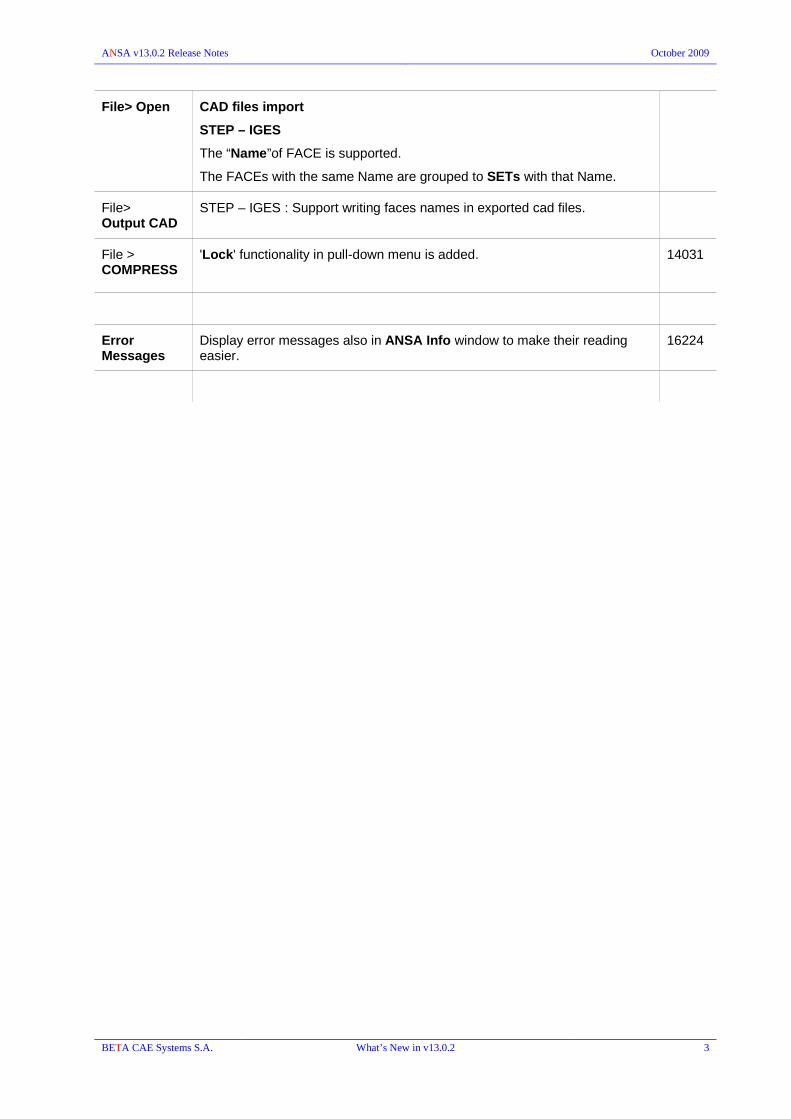
ANSA v13.0.2 Release Notes October 2009
File> Open CAD files import
STEP – IGES
The “Name”of FACE is supported.
The FACEs with the same Name are grouped to SETs with that Name.
File> Output CAD
STEP – IGES : Support writing faces names in exported cad files.
File > COMPRESS
'Lock' functionality in pull-down menu is added. 14031
Error Messages
Display error messages also in ANSA Info window to make their reading easier.
16224
BETA CAE Systems S.A. What’s New in v13.0.2 3

ANSA v13.0.2 Release Notes October 2009
General Buttons:
D.UTIL The RENUMBER button is now located in the D.UTIL group of buttons in the Common General buttons. It has been removed form the Auxiliaries Group of the Deck Modules.
GEOMETRY TRANSF.
The "Finish" button does not exit the function, allowing for a new selection of entities like the MiddleMouseButton and Enter key do.
15186
MEASURE:
The measurement type is shown in the edit card of the “Measure Entity”. Therefore the type could be changed in order to transform the stored measurement in a different one. The pulldown in the edit card includes only the possible measurement transformations (the same that are included in the pulldown during the MEASURE>NEW).
FOCUS ISOLATE> LOGOS: indicates the logos shown like small ribs, from faces
ISOLATE> BOUNDS :
works on 'Macro Areas' for 'SINGLE' and 'TRIPLE' bounds. The whole 'Macros' are isolated.
14774
Database Browser
Filters Tab Evaluate option is available in the right-click menu on a list name, in order to evaluate all filters of the selected list.
BETA CAE Systems S.A. What’s New in v13.0.2 4

ANSA v13.0.2 Release Notes October 2009
TASK Manager
ABAQUS Checks/Fixes: Fastener Eccentricity check is added. 15040
Mass Balance Script Reader item is now available
Data Management
Save Representation:
"Skip" option has been added in Save Representation dialog box. User is prompt regarding saving groups or inner parts representations and overwriting or creating new study versions for a given representation.
Read model definition:
Until now it was not allowed to delete a group of empty linked parts, that are auto-created, without deleting the parent parts. Now you can choose whether you want just the linked or the parent parts deleted as well.
16003
BETA CAE Systems S.A. What’s New in v13.0.2 5

ANSA v13.0.2 Release Notes October 2009
CAD Data Translators
The distance between the thickness lines (-layer_thic) is now returned. It is stored in the MatVecThickness variable, available through ANSA_TRANSL functions.
Changes in PID assignment. Now the colors of distinct bodies are the same with those in the CAD models, regardless of the -col2pid option.
However, if the -lay2pid or -singlepid are specified, colors will not be the same with the original cad model, since PID creation depends not on bodies or colors.
NX6 data can be translated
JT translators now work with version 5.0 of the Toolkit API
CAD Data Translator gui
NX : Added a directory list button that can be used to create the searchdirs.txt file which is necessary for the NX translator.
15052
BETA CAE Systems S.A. What’s New in v13.0.2 6

ANSA v13.0.2 Release Notes October 2009
Connections & Assembly
Settings Windows>Options>Settings>Connections
A new setting for the configuration of the mesh reconstruction that is performed by the FE-Repr. application, e.g. SPIDER2. If the checkbox is enabled the mesh parameters, i.e. mesh size, feature line detection, etc, through the “Mesh Parameters” window (MESH>SHELL MESH>PARAM.) will be used, otherwise internal default values will be taken into account. Thus, if configuration of mesh parameters is required, activate the option and proceed to the configuration via the PARAM. Function.
Currently the new setting is used only by the SPIDER2 FE-Representation.
Create Connections
TOPO & MESH>WELD SPOTs> DEF. CNCTN>MANUAL
The “Edges” selection option is supported for : Multiple Connection Points: and :Connection Curves” creation.
Moreover, for “Edges” and “Perimeters” selection, the 'curve' can be formed either on the selected line or in the “middle” in case of curve pair selection. supports edges.
When middle curve preview can not be produced a temporary warning message is shown. Middle curve preview is not produced when only one perimeter or line edges are selected or when the selected edges or perimeters have too different lengths.
!!! Even though for the selection of edges, box selection is available, it should be preferred for easier deselection rather than selection. The angle of "feature line window" is suggested to be used to define the preview curves.
13633
The CONVERT function is now available also in MESH>WELD SPOTs 5011
TOPO/MESH >WELD SPOTs>CONVERT> FE to Seamline
CWELDs,only ALIGN type, can be converted to seamline connections.
BETA CAE Systems S.A. What’s New in v13.0.2 7
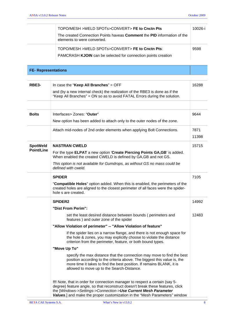
ANSA v13.0.2 Release Notes October 2009
TOPO/MESH >WELD SPOTs>CONVERT> FE to Cnctn Pts
The created Connection Points haveas Comment the PID information of the elements to were converted.
10026-i
TOPO/MESH >WELD SPOTs>CONVERT> FE to Cnctn Pts:
PAMCRASH KJOIN can be selected for connection points creation
9598
FE- Representations
RBE3- In case the “Keep All Branches” = OFF
and (by a new internal check) the realization of the RBE3 is done as if the “Keep All Branches” = ON so as to avoid FATAL Errors during the solution.
16288
Bolts Interfaces> Zones: “Outer”
New option has been added to attach only to the outer nodes of the zone.
9644
Attach mid-nodes of 2nd order elements when applying Bolt Connections. 7871
11398
SpotWeld Point/Line
NASTRAN CWELD
For the type ELPAT a new option 'Create Piercing Points GA,GB' is added. When enabled the created CWELD is defined by GA,GB and not GS.
This option is not available for Gumdrops, as without GS no mass could be defined with cweld.
15715
SPIDER
"Compatible Holes" option added. When this is enabled, the perimeters of the created holes are aligned to the closest perimeter of all faces were the spider-hole s are created.
7105
SPIDER2
"Dist From Perim":
set the least desired distance between bounds ( perimeters and features ) and outer zone of the spider
"Allow Violation of perimeter" -- "Allow Violation of feature"
if the spider lies on a narrow flange, and there is not enough space for the hole & zones, you may explicitly choose to violate the distance criterion from the perimeter, feature, or both bound types.
"Move Up To"
specify the max distance that the connection may move to find the best position according to the criteria above. The biggest this value is, the more time it takes to find the best position. If remains BLANK, it is allowed to move up to the Search-Distance.
!!! Note, that in order for connection manager to respect a certain (say 5-degree) feature angle, so that reconstruct doesn't break these features, click the [Windows->Settings->Connection->Use Current Mesh Parameter Values.] and make the proper customization in the “Mesh Parameters” window
14992
12483
BETA CAE Systems S.A. What’s New in v13.0.2 8

ANSA v13.0.2 Release Notes October 2009
before the connection Apply.
Otherwise, connection manager will use internal default mesh parameter values.
Adhesive Lines
CONTACT
A Tie Contact is created.
The slave set contains nodes collected from P1 part according to a detection distance and the master set contains properties from elements from P2 part found in a search distance.
The Width [W] of the connection is used as the detection distance. If width is 0.0, the slave set will contain all nodes of all elements from P1 found in a search distance.
Contact ID:
-If "Contact ID" is given and corresponds to a valid contact, the given contact is used as a template and one new contact will be created by copying the template.
-If "Contact ID" is not given, Connection Manager will look for a contact whose master set contains the shell properties needed.
If no matching contact can be found, a new will be created.
In case "Contact ID" is not given, the search distance is used as POS_TOLER in the TIE card.
14369
Adhesive Faces
RBE3 : new representation.
The REFGRID Nodes of RBE3s are searched from connection face to part P1 within search distance. For every REFGRID Node the other nodes are searched to part P2 within search distance.
If RBE3 diameter is BLANK or ZERO, only the nodes of nearest, to the REFGRID node, shell are assigned to RBE3. Else, all nodes from projection point ( of Ref Node to nearest shell ) within Rbe3 diameter are assigned to Rbe3 too.
15687
HEXA-CONTACT , COHESIVE-CONTACT
"Create Single Contact" option is added.
15330
Seam Lines
NASTRAN CWELD: new representation.
Creates CWELD type "ALIGN" for Seamlines
15572
SHELL-CONTACT : Seam lines new representation realization using shell plus tied contact
W is considered as the thickness of the the seam-weld shells.The shells are not pasted with the connected parts.No reconstruction on underlying surfaces.Interfacing achieved using tied contact (shell edge2surface + offset option).The projection method will always be normal projection from the connection curve to the 2 parts, regardless of feature lines around. This means that when realizing e.g. a T-weld, the weld-shells will not be necessarily vertically projected to the flange, neither necessarily attached to the feature line. It will all depend on the connection curve positioning.
8887
BETA CAE Systems S.A. What’s New in v13.0.2 9

ANSA v13.0.2 Release Notes October 2009
Y-JOINT-SHELL:
“Keep Adjusted Shells” new option. If it is enabled the shells that correspond to the "height" adjustment on Y-JOINT-SHELL are not erased. Therefore a blue bound between the weld shells and the secondary sheet shells is defined.
15187
CONNECTORs
Search methods PassThrough option has been added.
ResultsFromSet option has been removed; it can be achieved with Connectivity = SET and Search Method = PassThrough
BETA CAE Systems S.A. What’s New in v13.0.2 10

ANSA v13.0.2 Release Notes October 2009
BATCH Mesh Manager
Mesh Parameters
Fillets:
Chamfer treatment
"Do not join perimeters created from split treatment" is used for both, fillets and chamfers.
Holes Treatment
The tab of Tubes is removed : the tubes treatment is now controlled within the holes tab.
BETA CAE Systems S.A. What’s New in v13.0.2 11

ANSA v13.0.2 Release Notes October 2009
Some parameters of holes and tubes made common:
- "Create perimeters on zones"
- "Attach zones"
Holes Treatment
Specify the hole's Node Number also by giving :
• the hole's perimeter element length (L0), or
• a zone's perimeter element length (maximal 15 zones, L1-L15),
In addition the node number can be defined as :
• a product of the target element length (*L), or
• the minimum element length (*Lmin).
The ansa_mpar file is also changed in order to support the new features (N=, L0=, L1=, L2=, etc.).
Fix Quality : elements suffering by Maximum Element Length criterion can be now corrected.
Volume Scenario
Layers Scenario
Volume / Layer sessions
The “Copy to F11” is added in the sessions Quality Criteria window
The “Isolate And Copy Params" is added in the Right Click menu onto the Layers and Volume sessions.
16130
PART Manager
GEB_xx The functions Replace, Delete and Save are now able to handle GEB_SB (set builder) and GEB_GN (general builder)
BETA CAE Systems S.A. What’s New in v13.0.2 12

ANSA v13.0.2 Release Notes October 2009
TOPO
FACEs RM.LOGOS
PER FACE : removing “logos” by selecting the faces upon which the “logos” stand
AUTO: automatic detection of the “logos” faces to be removed
DACH
chamfer fillets can be detected and treated by the function (for sharpen or split)
CHECK GEOMETRY: Break surfaces is supported in fix application.
GEOMETRY > Needle Faces.
Added fix for needle faces due to resolution.
14178
BETA CAE Systems S.A. What’s New in v13.0.2 13

ANSA v13.0.2 Release Notes October 2009
MESH
PERIMETERs A.SPACING>CFD
the spacing accepts angles lower than 1 (one) degrees.
Improved speed of A.SPACING >CFD 15728
LENGTH : Feature selection>Feature Line is available 10128
MACROs CREATE function is restored
SHELL MESH FILL>Gap>Edges : can select 3D-curves 12513
Fill>Gap>Coons : is able to select edges/perimeters/curves without the need of selection mode (radio buttons) window. A new preview is also available.
12513
FIX QUAL : function is now able to correct elements suffering by Maximum Element Length criterion.
UTIL
The projections are now performed on each different part or pid instead of finding the closest one
UTIL
A pull down menu gives access to the function list.
Each function is applied onto selected entities. The application on the “Visible” entities has been removed.
Once a function has been selected there is still a chance to use a different one as this can be defined in the “Utilities Parameters” window by the Mode option:
BETA CAE Systems S.A. What’s New in v13.0.2 14

ANSA v13.0.2 Release Notes October 2009
RESHAPE: Preview is available when the function applied onto FE-mesh 15925
ELEMENTs WRAP > [Variable length] : now it takes into account the Size Boxes 14840
PENETRATION
Solid Elements have thickness only for current Deck modules LS-DYNA and ABAQUS. In all other decks, property thickness penetration between shells and solids is detected only if the solid gets “inside” the shell's thickness.
16559
VOLUMEs Volume Mesh Generators are now able to mesh Volumes with more than 1000 sub-volumes.
13272
MAP > Thin Parts :
New function to be applied onto curved thin parts. The created map mesh orientation will follow the shape of the master shells and will be perpendicular on them.
MAP : the selection order for the straight transition has been changed. Thus, the path of transition is given just after the selection of the master and slave surfaces and not at the end.
14333
EXTRUDE>OFFSET
The offset distance value can be specified from the screen, i.e by picking two positions.
15242
EXTRUDE : the created solids have now the same number of pids (instead of only one pid) as the root shells. Thus, if the selection of the root shells contain two properties, then two solid properties will be created.
16516
Mesh Parameters
Holes Treatment
Specify the hole's Node Number also by giving :
• the hole's perimeter element length (L0), or
• a zone's perimeter element length (maximal 15 zones, L1-L15),
In addition the node number can be defined as :
• a product of the target element length (*L), or
• the minimum element length (*Lmin).
The ansa_mpar file is also changed in order to support the new features (N=, L0=, L1=, L2=, etc.).
BETA CAE Systems S.A. What’s New in v13.0.2 15
ANSA v13.0.2 Release Notes October 2009
Mesh Parameters
All parameters that define the target length are now written in the ansa_mpar file (from SHELL MESH>PARAM.).
The new entries are written under the "element-length" and are:
a) target_element_length_radio (accepts: Specified, Average, Free)
b) target_element_length_factor (accepts: a float number > 0)
c) target_element_length_param (accepts: init_average_len, init_local_len)
14702
Quality Criteria Color for min and max length in F11 for the HIDDEN drawing mode are now separated from each other.
15540
BETA CAE Systems S.A. What’s New in v13.0.2 16

ANSA v13.0.2 Release Notes October 2009
DECKs
Input / Output Update of the IDEAS-M format in order to include Universal Dataset Number 151.
15195
GRIDs/ NODEs PASTE>AUTO>SELECTED NODES: selects by node's feature angle.
ELEMENT UTIL>Change Type>1-D Entities:
Changing from line elements with no orientation (e.g. TRUSS) to elements that require orientation (e.g. BEAM) does not create non-accepted elements (i.e. collinear orientation axis) but elements with default orientation. Mind, however, to verify the result.
16092
AUXILIARIES BOLT: Added option to attach only to the outer nodes of the zone.
BOLT : The bolt axis is corrected to pass through the center of the smallest hole.
DB Browser – Lists
Properties/ Materials
Materials' Mapping List is now available also from "MATs SYNC" window of property list.
15216
Curves / Tables
Improved performance when reading huge files with tabular data (e.g. with more than 120000 lines)
Respecting of blank spaces when used as separator of columns. However, if other separator is used (e.g. colon) no blank spaces should exist before or after the separator.
15083 (ii-iii)
BETA CAE Systems S.A. What’s New in v13.0.2 17

ANSA v13.0.2 Release Notes October 2009
SAFETY FMVSS 201U
Target points detection - generation for all the vehicle's interior components.
The FMVSS Tool is used for the calculation of the target points and the positioning of the FMH (Free Motion Headform) for the simulation of the occupant protection in interior impact laboratory test according to the FMVSS 201U standard
FMVSS 201U Interface separated in three tabs :
Target Points - Positioning - Manual Operations.
Target Points: The user has to feed the tool with a number of sets (Vehicle Components Set) and a number of points (Seating Reference Points), in order to calculate the target points. With the Get Target Points ANSA calculates the needed planes and derives the characteristic curves and the target points. At the same time that approach angles for each point is automatically calculated and are set in the appropriate fields in the Positioning tab. The created planes, curves and points are stored in sets with the prefix FMVSS201U. With the Undo All the user deletes all the above.
Positioning: This tab is used to position the FMH to the target points according the FMVSS 201U regulation.
Manual Operations: This tab is used to manually position the FMH.
BETA CAE Systems S.A. What’s New in v13.0.2 18
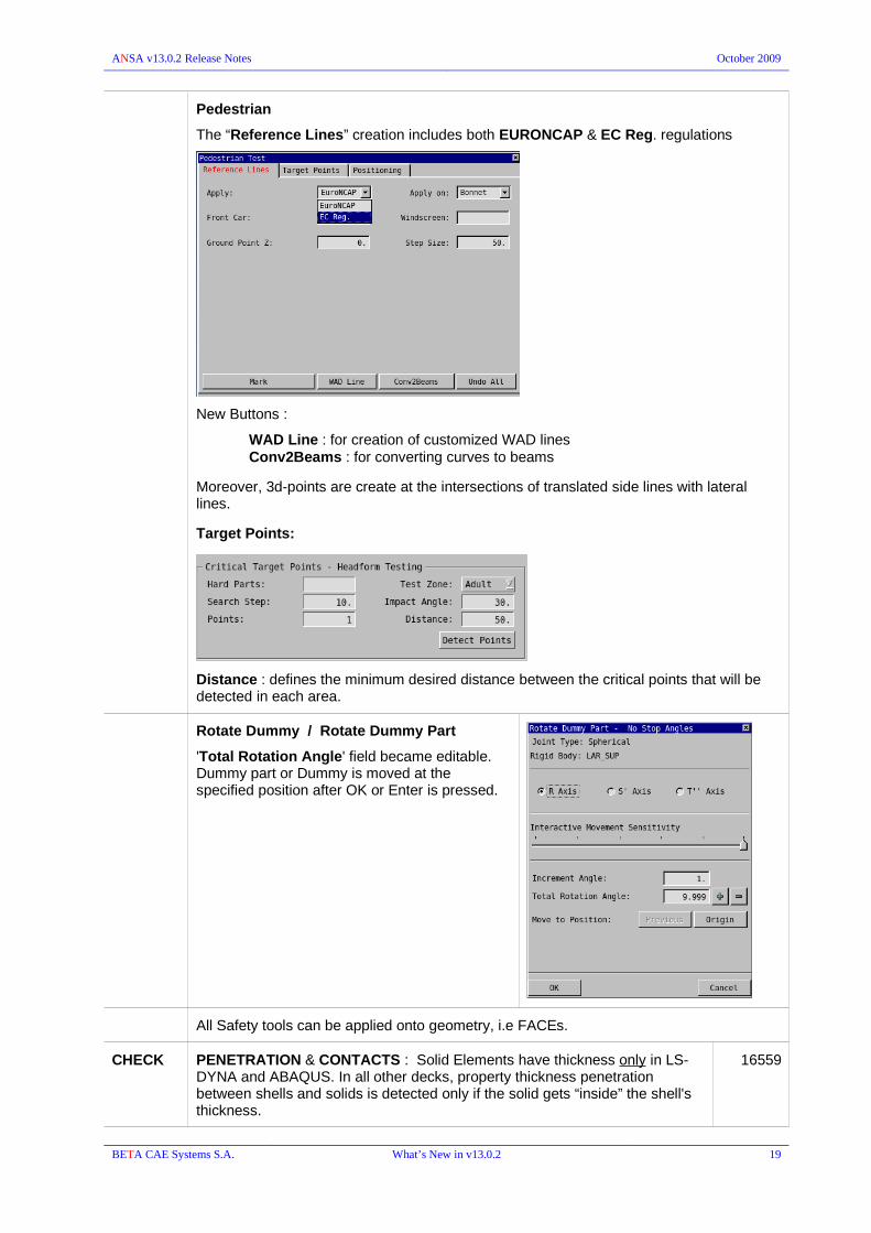
ANSA v13.0.2 Release Notes October 2009
Pedestrian
The “Reference Lines” creation includes both EURONCAP & EC Reg. regulations
New Buttons :
WAD Line : for creation of customized WAD linesConv2Beams : for converting curves to beams
Moreover, 3d-points are create at the intersections of translated side lines with lateral lines.
Target Points:
Distance : defines the minimum desired distance between the critical points that will be detected in each area.
Rotate Dummy / Rotate Dummy Part
'Total Rotation Angle' field became editable. Dummy part or Dummy is moved at the specified position after OK or Enter is pressed.
All Safety tools can be applied onto geometry, i.e FACEs.
CHECK PENETRATION & CONTACTS : Solid Elements have thickness only in LS-DYNA and ABAQUS. In all other decks, property thickness penetration between shells and solids is detected only if the solid gets “inside” the shell's thickness.
16559
BETA CAE Systems S.A. What’s New in v13.0.2 19

ANSA v13.0.2 Release Notes October 2009
NASTRAN
D.UTIL D.INFO : mass report takes into account CONM1 elements and report them accordingly in the MASS INFORMATION Table.
15967
ELEMENTs CWELDs > ELPAT / PARTPAT.
The Piercing Points GA and GB, can be created onto the connected patches by activating the option of the dialog box that pops up.
PARTPAT: Allow multiple CWELD definitions by selecting multiple GS nodes.
ELPAT: when the “Create Piercing Points GA, GB” is enabled and NOT GS is picked (middlemouse is used to skip GS selection) the CWELD is created without GS but only with the GA and GB piercing points.
15715
SOL200 Topology (TOPVAR), Topography (BEADVAR), Topometry (TOMVAR) are supported.
CHECK CWELD
A new errors detection function is added to identify :
“invalid projections”,
“invalid agnle between patches”,
“not shell nodes used as GA,GB in type ALIGN”,
“missing patches” etc .
in the CWELDs according to NASTRAN welding realization.
Fix option is available (where possible) to automatic correct the detected problems, i.e move the GS to a proper location for a successful projection.
58
6735
7115
CFAST
Detect projection errors for the CFAST realization
BETA CAE Systems S.A. What’s New in v13.0.2 20

ANSA v13.0.2 Release Notes October 2009
ABAQUS
ABAQUS version 6.9 is supported
Output Angle values throughout of (90, -90) range specified within Shell Element cards are now preserved in the exported abaqus deck file since it is now supported by Abaqus (> v6.8) as well.
15533
Abaqus keywords *INTERACTION PRINT and *INTERACTION OUTPUT are valid only for Abaqus versions < 6.8
Keywords:
*CONTACT
*CONTACT INCLUSIONS
*CONTACT EXCLUSIONS
*SURFACE PROPERTY ASSIGNMENT
are also supported in ABAQUS/Standard for versions > 6.8
Materials CONNECTOR BEHAVIOR
Support option DEPENDENCIES in *CONNECTOR ELASTICITY
10815
Materials *ACOUSTIC MEDIUM is supported.
9715
BETA CAE Systems S.A. What’s New in v13.0.2 21

ANSA v13.0.2 Release Notes October 2009
INIT.CONDIT. INITIAL : Support of *INITIAL CONDITION, TYPE=NODE REF COORDINATES (ABAQUS v6.9)
STEP Support of *MODAL DAMPING, *GLOBAL DAMPING 9816
12628
13909
Support of *SELECT EIGENMODES (for Abaqus 6.9) and *RETAINED EIGENMODES (for Abaqus v6.8 and earlier)
12893
15882
CONTACT Support MINIMUM DISTANCE option for *CONTACT PAIR ( for Abaqus versions >= 6.9 )
CHECK CLOSED TIE LOOPS: Detects tie contact loops 14334
BETA CAE Systems S.A. What’s New in v13.0.2 22

ANSA v13.0.2 Release Notes October 2009
LS-DYNA
LOAD BLAST: Support of *LOAD_BLAST_ENHANCED. 15089
INITIAL Support of *INITIAL_AXIAL_FORCE_BEAM card 16345
Materials Extend acceptable values of "HR" field of Ls-Dyna MAT_036 to 7.0 and MAT_190 to 6.0
Support *MAT_ADD_EROSION per LS-DYNA 971 R4 requirements:
Added "EFFEPS", "VOLEPS", "NUMFIP", "NCS" fields at MAT_ADD_ERROSION first card.
16010
CONTACT Additional option on CPARAM8 (=2) field of the *CONTACT_MPP card 16542
CONTROL Support of "BMSID" and "ID_OFF" fields of CONTROL_SPOTWELD_BEAM.
16383
AUXILIARIES DFRMBLE : *DEFORMABLE_TO_RIGID_AUTOMATIC
Several improvements for easier and error proof selections.
During new creation, only deformable properties can be selected for D2R and R2D PIDs. Also only rigid property can be selected for MRB.
In edit card PID fields are mandatory (zero or blank are not acceptable) and a check is performed if they are deformable. If MRB parts are defined, a check is performed if they are rigid (check >model data).
By pressing F1 in a PID field, only deformable properties remain visible for selection and only rigid for F1 in MRB fields. Also pressing "?" in property fields provide a selection list with compatible properties (deformable/rigid depending on the case)
15352
BETA CAE Systems S.A. What’s New in v13.0.2 23

ANSA v13.0.2 Release Notes October 2009
PAM-CRASH
SAFETY Rot Dummy > Rotate Dummy Part : Joint's info is got by the kinematic joint. This gives user the choice to set up manually the stop angles by editing the kinematic joint's card, where the angle values fields became editable.
CHECK PENETRATION & CONTACTS :
Penetration between shells and solids is detected only if the solid gets “inside” the shell's thickness.
16559
BETA CAE Systems S.A. What’s New in v13.0.2 24

ANSA v13.0.2 Release Notes October 2009
ANSYS
Input Extension in reading ANSYS keywords EN and R.
Also support ANSYS keywords TYPE, RMORE, REAL, MAT.
9808
The ID for the Property (PID) that the element has in ANSA is now taken by the REAL sets (if exist).
14144
Every mass that has the same data (mass values) with another one, points to the same REAL.
9326
ANSA Info Echo ANSYS keywords SPC, CERIG, RBE3, CE, CP and materials in ANSA Info window, during info-pick and edit from list.
10372
NODE UTIL
The options "Change CSYS" and "Change NODAL COORD" have been added.
7219
ELEMENTs SOLSH [NODE || ELEM]
Support of element type SOLSH190; type specified within the “Property card”.
It can be created by picking nodes, upon shell elements or by converting solid elements.
SFE loads can also be applied on facets of SOLSH190 elements.
SOLSH190 facets can be added in ANSA sets in order to apply SFE on them or to be used properly by contacts.
8492
13395
BETA CAE Systems S.A. What’s New in v13.0.2 25

ANSA v13.0.2 Release Notes October 2009
JOINT > [TWO NODES || ONE NODE]
Support ANSYS joints : element type MPC184.
The following MPC184 elements has been supported:
LINKBEAMREVOLUTEUNIVERSALSLOTSLIDEPLANETRANSLATIONALCYLINDRICALPLANARWELDSPHERICAL
Supported keywords:
SECJOINTSECSTOPSECLOCK
3626
10400
Support ANSYS 2nd order shell element ET 281. 14531
Support ANSYS element type COMBIN40. 14532
Support ANSYS element type PLANE183. 14530
Support element types :
FLUID29, FLUID130 (shell)
FLUID30 (solid)
FLUID129 (beam)
CONTACT Assign default values in real constants of Contact card.
Every new created contact in ANSA, get the default values for ANSYS reals, according to table 3.1 of Contact technology Guide, section 3.8.1 of ANSYS 11.0 manual. Thus all created contacts have always real values.
14687
PRTENS Support of PRETS179 : Pre-Tension Section
Pretension Section Assistant is available for quick and easy definition of ANSYS pretension.
8493
CHECK MODEL DATA
Detects Shell or Solid elements that are 2nd order and are wrongly assigned an ET that corresponds to 1st order Element and vice versa.
With this new option the abaqus models that are switched to ANSYS can be verified regarding the correct Element Type assigned to 2nd order elements.
14539
BETA CAE Systems S.A. What’s New in v13.0.2 26

ANSA v13.0.2 Release Notes October 2009
CFD Decks
Size Boxes are also used by WRAP [Variable Length]
CFX OUTPUT: avoid writing shell_properties not matched to solid-facets as boundary conditions
STAR AUXILIARIES> SOLVER INFO :
specifies the solver :STAR_CD or STAR_CCM.
The property field type can take now BC types only of the specified solver.
StarCCM output baffles are output oriented uniformly.
PERMAS
New supported keywords
$TRANSLOAD
$FUNCTION TABLE
$MODDAMP
$PARAMETER
15073
LOADING PRETENSION : define Pretension Load for Bolt modeling.
AUXILIARIES PRETENSION > [PLANE || THREAD] : Pretension definition for bolt modeling.
The CONNECTOR button has been added.
BETA CAE Systems S.A. What’s New in v13.0.2 27

ANSA v13.0.2 Release Notes October 2009
MORPH
Hatches The cross-hatches onto Morphing Box faces are drawn as dashed lines (like the Geometry Faces)
Link boxes
Frozen Control Points
Color of Frozen Control Points of linked Morphing Boxes becomes orange (the same as for the original Morphing Boxes) when the “Freeze” toggle button is enabled.
16194
CONTROLS PARAMS : the LENGTH parameter renamed to EXTEND 15340
BOXES LOAD > [NOTLOADED]
This function highlights entities that are not loaded to any Morphing Boxes.
11054
MODIFICATION MOVE : Specifying local coordinate system in morphing actions is done by right mouse click without the need of special button. The elements do not get transparent so their local coordinate can be picked. Moreover, the selected Coordinate System is preserved as long as the function is active for modifications.
15374
MOVE : Selection of Morphing Box local coordinate system is enabled. 15350
MODIFICATIONS / DIRECT MORPHING
MOVE > TRANSLATE / ROTATE & DIRECT>NODES :
the movement is applied as soon as the Middle-Mouse-button, Enter or Apply is hit and not automatically.
DIRECT MORPHING
DEPRESS
Function creates triangular mesh if the meshing type (MESH TYPE) is switched to TRIA (MESH>MESH GEN.>TRIA)
8415
BETA CAE Systems S.A. What’s New in v13.0.2 28

ANSA v13.0.2 Release Notes October 2009
Optimization
TOSCA Structure Pre-Processing: “Convert From Model” option is added.
TOSCA error log can be saved as html.
"Monitoring Process" is available during optimization run.
TOSCA Smooth : Allow multiple Smoothing Instances per Task.
START OPTIMIZATION: New Task Items Convergence Plot and View Tosca Out.
Optimization Task In Run_mode=Execution : edit in Design Variable is allowed for Min / Max and Current values fields.
NASTRAN SOL-200 Simulate:
The Simulation functionality has been added for the SOL 200 to animate and simulate the shape changes that occur from the DESVARs that are connected to DVGRIDs.
A Fringe plot with contour colors of the virtual displacements as an effect of the corresponding Design Variables is displayed. Mind to have the F11>Graph Parameters> Color_Bar_colors=Pallet
Topology (TOPVAR), Topography (BEADVAR), Topometry (TOMVAR) are supported.
These are also available within the NASTRAN Loadcase Design Optimization in the TASK Manager.
12901
BETA CAE Systems S.A. What’s New in v13.0.2 29

ANSA v13.0.2 Release Notes October 2009
DRESPi : New Response types Compliance (COMP) and Mass Fraction (FRMASS)for topology optimization
DOTPRM : Parameters added: TCHECK , TDMIN
BETA CAE Systems S.A. What’s New in v13.0.2 30

ANSA v13.0.2 Release Notes October 2009
SCRIPTING
GetNormalVectorOfShell : New built in function(the script GetNormalOfShell.bs is removed from the script collection packagesince it becomes obsolete).
CollectEntites accepts a Connection Point as a container argument. 11578
VolumesMeshV : New built in function
NearElements script function now accepts multiple 3d points as input to speed up calculation.
ReleaseElements : accepts a matrix argument 14485
IsolateAndCopyParameters function for script. 9814
HideWindow : new function in script library
AutoSetConnectivityInConnections : “Auto” function of connection manager 15334
CenterConnections : "Center" function in Connection Manager
AddToSet : can now add entities as EXCLUDED.
EraseConnectionFeRep : "Erase FE" function of Connection Manager
ConvertFeRepToConnection : New built in function
15607
Script functions RunSession, RunMeshingScenario, RunSessionGroup, RunAllMeshingScenarios return 0 if check button is closed, 1 if everything is OK, and 2 if something hasn't run.
Script functions RunSession, RunMeshingScenario, RunAllMeshingScenarios have one extra argument. That argument is a time limit in minutes. If that limit is exceeded then batch mesh process is halted. Old calls of these functions will work normally using 0 time limit.
15445
SetEntitiesPart : New script function that assigns to a parent part a matrix of elements.
CollectBoundaryNodes : New built in function 155143749
CheckGeometry: New built in function
GetConnectionSettings: gets any parameter from a connection with a keyword. 15806
In script function PickEntities when:1. User sets "SHELL" as keyword, shells from macros, fe can be selected with angle selection.2. If sets "SOLID"/"SOLIDFACET", then solids/facets from volume or fe can be selected with angle selection.3. If sets "FACE", can select faces with angle selection. If is in TOPO menu then the angle selection is based on faces neighborhood. In other case selection is
3265
BETA CAE Systems S.A. What’s New in v13.0.2 31

ANSA v13.0.2 Release Notes October 2009
based on angles between shells.
In script function PickNodes when:1. User sets "VOLUME" as keyword, nodes of solid elements of a volume can be selected with angle selection.2. If sets "FACE", then nodes of shell elements of a macro can be selected with angle selection.3. If sets "SHELL"/"SOLID", nodes of shell/solid elements can be selected from macros/volumes with angle selection and there is and option to select nodes of elements (user selects element, but only nodes are returned).
SetEntityPart now works with matrices of elements as well.
New built in script functions: RotateDummyPart, RotateDummyAroundHPoint and TranslateDummy
New built in function : AssignConnectionSettings : assigns the desired settings to the connection without creating FE representation.
New built in function: MoveGridsToOrigin. 9582
New script function : CalcQCHECK : It calculates the QCHECK value of all components included in the matrix.
5068
New script function : KinematicsConvertToNMap
New script function : IsolateBaffles
New script function: AparameterTaskItemLinkToAparameter
Added an argument mode at 'RotateDummyPart' and 'RotateDummyAroundHPoint' script functions. If mode = 0 then the angle argument is the increment angle, else if mode = 1 the angle argument is the total rotation angle for the selected rigid body.
BETA CAE Systems S.A. What’s New in v13.0.2 32

ANSA v13.0.2 Release Notes October 2009
Script collection
Folder: ANSA_TRANSL
ANSA_TRANSL_material_vector ANSA_TRANSL_read_attr_files ANSA_TRANSL_Read_CAD_header (new file) ANSA_TRANSL_Read_extra_options_field (new file)
Folder: PostRealization
PostRealize_PrintArgs.bs (new file) PostRealize_SpiderCbarToCbeam.bs (new file) PostRealize_ChangePbeam.bs PostRealize_PIDsInComment.c (new file)
SplitBeams New script that Splits each beam in two, while is keeping the original properties
DesignVariablesParametrizeThickness For each selected shell property, the function creates an A_PARAMETER for the thickness and a Design Variable that controls it. An Optimization Task must have been created in advance. The Design Variable is named PSHELL_<PID>_T and is of type REAL.The current thickness is set as Current Value. The Min/Max values are calculated based on user specified factors.
RedConsGridsInSet ( binary) Script is removed. The built in function CollectBoundaryNodes can do the job.
RedConsShellsTriasInSets (binary ) Script is removed. A new function BoundaryTriasInSet is added instead. This works in FE also.
AlphabetSorting and AlphabetSortingAllProps
are unified to AlphabetSorting
AlphabetSorting now works with any starting id
PropShellToSet Now the user doesn't have to type the property name
TriasToSet is removed from distribution This function is used to find trias that violate the min height. It seems to be obsolete since this criterion is now supported from ANSA.
FindNodesShells The function FindNodesShells was renamed to ShellsPerNode which describes better the functionality
PartName2Pid PartName2Pid was renamed to PartName2PropName to describe better the functionality. Also, now only PSHELLs are renamed and also it is not required the parts and properties to have the same pid.
IsolateSolids is removed since there are predefined filters in filters tab
ReportSets The function is removed since the set list displays the content of sets
GroupPropsReport Obsolete
UpdateAbqProperties.bs Function is removed. It is obsolete
CompressRbe2 The function CompressRbe2.bs is substituted by the
BETA CAE Systems S.A. What’s New in v13.0.2 33

ANSA v13.0.2 Release Notes October 2009
CompressRbe2Rbe3.bs
OpenCatiaInAnsa The function works in Windows too and now saves the ANSA file in the directory where the CAD file is located
OpenNXInAnsa The function was added in distribution. it works as the 'OpenCatiaInAnsa'
PedestrianWithIncludePam,PedestrianWithIncludeDyna,PedestrianWithIncludeRadioss,PedestrianWithIncludeAbaqus
Functions have been updated in order to take into account more separators when reading the file with points.
BETA CAE Systems S.A. What’s New in v13.0.2 34
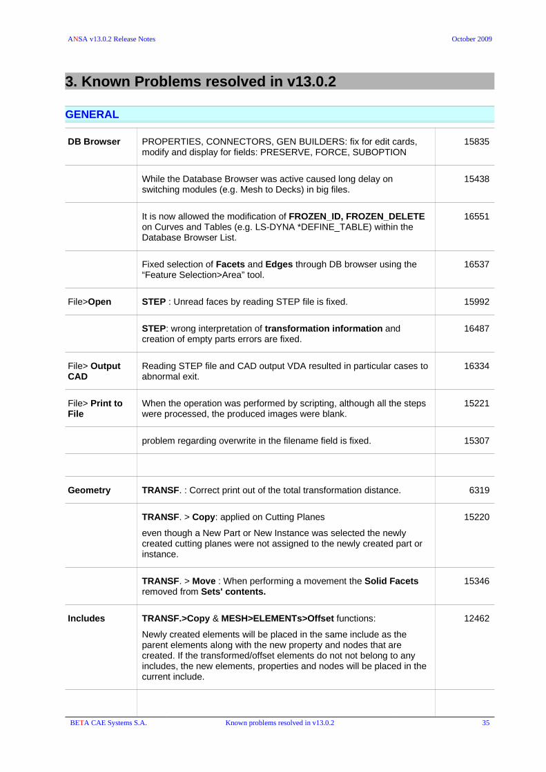
ANSA v13.0.2 Release Notes October 2009
3. Known Problems resolved in v13.0.2
GENERAL
DB Browser PROPERTIES, CONNECTORS, GEN BUILDERS: fix for edit cards, modify and display for fields: PRESERVE, FORCE, SUBOPTION
15835
While the Database Browser was active caused long delay on switching modules (e.g. Mesh to Decks) in big files.
15438
It is now allowed the modification of FROZEN_ID, FROZEN_DELETE on Curves and Tables (e.g. LS-DYNA *DEFINE_TABLE) within the Database Browser List.
16551
Fixed selection of Facets and Edges through DB browser using the “Feature Selection>Area” tool.
16537
File>Open STEP : Unread faces by reading STEP file is fixed. 15992
STEP: wrong interpretation of transformation information and creation of empty parts errors are fixed.
16487
File> Output CAD
Reading STEP file and CAD output VDA resulted in particular cases to abnormal exit.
16334
File> Print to File
When the operation was performed by scripting, although all the steps were processed, the produced images were blank.
15221
problem regarding overwrite in the filename field is fixed. 15307
Geometry TRANSF. : Correct print out of the total transformation distance. 6319
TRANSF. > Copy: applied on Cutting Planes
even though a New Part or New Instance was selected the newly created cutting planes were not assigned to the newly created part or instance.
15220
TRANSF. > Move : When performing a movement the Solid Facets removed from Sets' contents.
15346
Includes TRANSF.>Copy & MESH>ELEMENTs>Offset functions:
Newly created elements will be placed in the same include as the parent elements along with the new property and nodes that are created. If the transformed/offset elements do not not belong to any includes, the new elements, properties and nodes will be placed in the current include.
12462
BETA CAE Systems S.A. Known problems resolved in v13.0.2 35

ANSA v13.0.2 Release Notes October 2009
FOCUS ISOLATE>Single : used to keep also 1-D elements, i.e Bars, Rbodies, etc.
14132
ISOLATE>BAFFLES : Fixed error caused unexpected exit on WindowsXP platform.
GUI
Settings
When starting ANSA with the "-i" option and giving a CAD file (i.e vdafs, step, iges) the menu buttons on top of the GUI are "messed-up" and some lost their labels.
15012
Unnecessary warning messages were printed during buttons relocation.
15011
SHADOW In particular cases the Pause/Break does not halt the shading process. 16102
Pull down menus of buttons
On Windows platforms (XP an Vista) the mouse-release event for pull-downs of buttons did not activated the button's default option and the pull down menu remained visible with no option selected.
16174
BETA CAE Systems S.A. Known problems resolved in v13.0.2 36

ANSA v13.0.2 Release Notes October 2009
TASK Manager
Surf.Wrap Adding the "Surf.Wrap" item, Editing it and pressing Cancel/Esc in the window caused abnormal exit.
15022
Optimization task Could not export ABAQUS explicit in -nogui mode in an optimization task
15259
Connections Wrong message at 1st run of TM regarding Connection Status:
Spider & Bolts which support the 'Allow Single Part' feature, failed to pass the task-manager check.
15303
TOSCA Hitting Cancel/Esc did not discard the creation of a TOSCA task item.
15929
Several fixes in TOSCA Task creation and editing.
Model Checks / Fixes
ABAQUS : Check>Fastener
Now the check is performed for fasteners that belong to the task.
Convert from Model
Contacts of spotwelds are not merged into the Task. 12318
BETA CAE Systems S.A. Known problems resolved in v13.0.2 37

ANSA v13.0.2 Release Notes October 2009
Assembly & Connection Manager
Modifications of connections' values from connection manager, database browser or script became faster.
15037
15038
“Erase FE” removed not only the FE-Repr. Properties but also all the ones that were created as “Copy” (manually) of them.
16272
Realized Connections in old ansa files (older or equal to v12.0.2) appear as having status 'blank' instead of 'Ok' when open these files in v13.0.1
16277
Having the Connection manager docked, option "Edit Connection" did not work.
15965
ANSA.defaults with more than 100 entries in the mapping table thick__spw_diam caused abnormal exit in launching ANSA.
The maximum length of the array changed from 80 to 202.
16137
External Assembler
When the connection with External Assembler is made, the “Status” became <blank> and the “Error Class” became "CUSTOM FE".
15448
Connections Selection Assistant
Select spots of “Visible Props.” did not work on solid properties. 16593
Gumdrops RBE3-HEXA-RBE3 : misleading message "Internal error Validating Gumdrop" was printed although the connection was realized.
15560
Adhesive Lines
RBE3 diameter did not work for adhesive lines with regular distribution 15861
Hemming FOLDING : In many cases even though elements were successfully folded, the RBE3-HEXAs were failed. Algorithm that creates HEXAs on hemming is now much less error prone.
15683
Seam Lines Y-JOINT SHELL: Fix Y-Joint height adjustment so not to shrink the heat affected zones (HAZ). The HAZ width defined is now respected.
15309
SpotWeld Points/Lines
RADIOSS WELD: 'Use thickness to PID Map' option did not work when called a script function. This error first appeared in v12.1.5
15621
SPIDER2: Fixed error that caused abnormal exit on realization. 15756
NASTRAN CWELD: Fixed error that made unable the realization of CWELDS type ELPAT (no space for the spotweld area).
During the Cweld realization the elements to be created are checked if they satisfy the Nastran projection criteria. The Diameter within the PWELD is taken into account for this check. Therefore, for ELPAT & PARTPAT welds that are applied with a non existing PWELD-ID, this PWELD that will be auto-created, will have D (Diam) = 0, even though the connections may have D>0. If the PWELD diameter is modified later, the CHECK>CWELDs has to be performed manually.
Applying CWELDs with an existing PWELD ID (or with the PWELD field blank) the CWELDs to be created will be checked with the current diameter, thus they will fail if there is no space for the spotweld's area.
16190
BETA CAE Systems S.A. Known problems resolved in v13.0.2 38
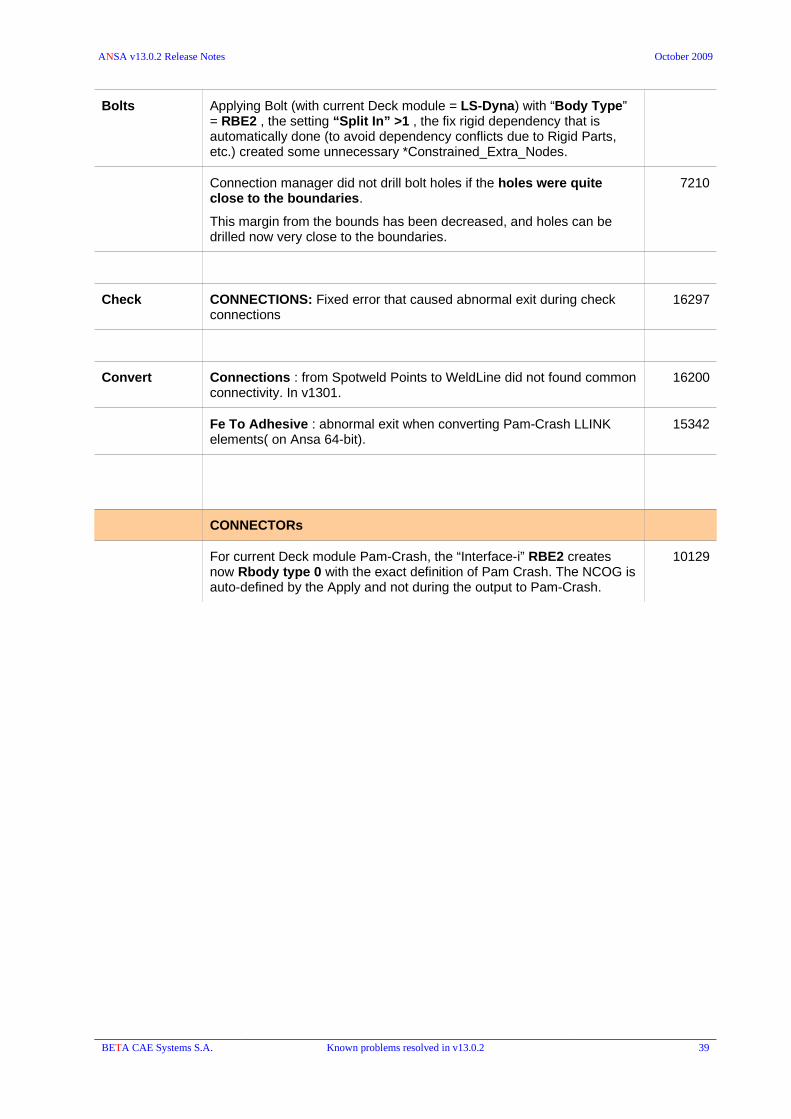
ANSA v13.0.2 Release Notes October 2009
Bolts Applying Bolt (with current Deck module = LS-Dyna) with “Body Type” = RBE2 , the setting “Split In” >1 , the fix rigid dependency that is automatically done (to avoid dependency conflicts due to Rigid Parts, etc.) created some unnecessary *Constrained_Extra_Nodes.
Connection manager did not drill bolt holes if the holes were quite close to the boundaries.
This margin from the bounds has been decreased, and holes can be drilled now very close to the boundaries.
7210
Check CONNECTIONS: Fixed error that caused abnormal exit during check connections
16297
Convert Connections : from Spotweld Points to WeldLine did not found common connectivity. In v1301.
16200
Fe To Adhesive : abnormal exit when converting Pam-Crash LLINK elements( on Ansa 64-bit).
15342
CONNECTORs
For current Deck module Pam-Crash, the “Interface-i” RBE2 creates now Rbody type 0 with the exact definition of Pam Crash. The NCOG is auto-defined by the Apply and not during the output to Pam-Crash.
10129
BETA CAE Systems S.A. Known problems resolved in v13.0.2 39

ANSA v13.0.2 Release Notes October 2009
BATCH Mesh Manager
Problem when changing the 'Fill' option to 'Spot' in Holes treatment; the change was not applied.
15075
When saving the layer parameters the file manager did not automatically fill the *.ansa_lpar in the filename.
15276
Save Session did not save parts correctly in the case where the scenario was PID based. 15071
Save Scenario: The File Manager did not open and the saving failed, in case of non-existent DM path.
15271
Fixed abnormal exit in batch meshing of particular case. 15158
Some FE shells were not highlighted from the batch mesh Parts window. 16425
Draw Sessions did not colored the parts of the session if
• FE elements (not geometry) was loaded in a session and
• were selected as PARTS/GROUPS
16428
PARTs Manager
Save Part Boundaries or Fasteners which belonged to a part were not saved correctly in the new ANSA file.
BETA CAE Systems S.A. Known problems resolved in v13.0.2 40

ANSA v13.0.2 Release Notes October 2009
TOPO
CONS PROJECT : double projection of faces. Fixed the problem , caused ONLY when the Feature are selection tool is activated and the selection is done by simple click on the CONS - not by box selection, and created unaccepted projection.
16055
PASTE: Problem with the selection of joined CONS which didn't have hot points on its boundaries; the selection continued to the adjacent double (yellow) CONS.
15324
FILL HOLE: if the "Convert point to connection point" was activated without activating the "Make point at center hole" flag no connections were created.
Now both options work independently to each other.
15250
FACEs MIDDLE>MULTI: Property assignment of new middle faces was wrong in a specific case, when exiting and re-entering the function to continue.
15629-vi
MIDDLE>MULTI: Fixed error that caused abnormal exit when using Auto & Trim manual on Unix HP UX11
16026
SURFs COONS and SURFs>SWEEP/GLIDE:
when selecting an element edge of FE-model mesh ANSA terminated unexpectedly.
15411
BETA CAE Systems S.A. Known problems resolved in v13.0.2 41

ANSA v13.0.2 Release Notes October 2009
MESH
SHELL MESH FILL>Hole: Unaccepted result was given if the selecting the hole was comprised between geometry and fe model.
16037
SUPPRESS : produced unaccepted results when it was applied on 2nd order elements.
15809
MACROs RELEASE>Keeping Mesh : results improved significantly 15794
PERIMETERs EDG2PER : fixed errors that caused unaccepted results. 14013
8556
EDG2PER : New perimeter segments that are created have, instead of last applied length, average length of the macro area the 'cut' shells belong.
6873
A.SPACING > [CFD] : Fixed error that caused abnormal exit on a particular case.
16191
GRIDs A.PASTE
When using "Selected Nodes" and activating "Project on Geometry", there was no projection. The projection performed only with "Selected Elements".
Having selected "geometry Pos", the nodes were moved to the “average position” and vice versa..
Malfunction of the "preserve ids" option has been also fixed.
15081
ELEMENTS EXTRUDE > SWEEP / GLIDE: fixed error that caused abnormal exit. 15123
SPLIT>[SOLIDS] did not allow the splitting of solids when the whole database was visible. Function worked only if remained visible an isolated small area around the solids to split.
15987
WRAP > [Variable length] if implying no contact among any PID (Contact Groups = 0), produced elements smaller than minimum length. Regardless of the specified length range ANSA refined down to 1. It checks now the “Min length” of each PID instead.
16169
VOLUMEs MAP : failed to remesh after cutting one macro but leave the same number of elements.
16278
MAP : correct misleading warning message (“Incompatible Master slave combination”) that was printed although the problem of the mesh generation was related to an existing volume definition.
16341
MAP: fixed error that caused heavily distorted solid elements. 15209
MAP : a message is printed if surfaces belongs to already defined 16225
BETA CAE Systems S.A. Known problems resolved in v13.0.2 42

ANSA v13.0.2 Release Notes October 2009
volumes.
MAP : fixed error that produced wrong and unaccepted mesh result when the function was applied onto 2nd order mesh.
16240
MAP: fixed error that led to abnormal exit on particular cases. Appeared only for 32bit ANSA v1301.
15318
MAP - Volume Remeshing :didn't work on copied volume definition, e.g. created by Geometry>TRANSF.>Copy. All the surfaces of the copied map-volume were marked as master.
15777
EXTRUDE > TRANSLATE : fixed error that caused abnormal exit related to Faces' and solid's facets selection using the Feature area.
15439
EXTRUDE>OFFSET : fixed error that caused unexpected termination. 16238
IMPROVE> FIX QUAL for 2nd order Shells and Solids( in order to improve Jacobian, Mid.Point Alignment, Mid.Point Deviation) did not work on Macro Area and Volume Definition.
15200
Quality criteria Increased precision for the values given in the cells of the quality criteria. Values are rounded on the 10th decimal position. Change of values is now avoided.
15456
QGRAPH drawing mode
Fixed problems of recalculation/refresh of Quality Graph display for Mesh Distortion, Distance From Geometry, Distance From Origin criteria.efresh problems appeared also after applying TRANSF>MOVE or ELEMENTs>OFFSET.
14929
16038
Fixed error regarding “Mesh Distortion” calculation and display on Cylindrical Faces.
4542
QGRAPH
S.GRAPH
QGraph>Mesh Distortion & S.Graph: Fix in drawing of elements on perimeters which are between no-tangent faces, if the faces are Offset Linked faces.
10306
BETA CAE Systems S.A. Known problems resolved in v13.0.2 43

ANSA v13.0.2 Release Notes October 2009
DECKs
Output Output Parameters window > General > Ansa Comments
Although the "Above keyword" option was selected, the comments were written “At the End of File” and vice versa.
15104
Output Parameters window > Miscellaneous > Thickness
When exporting element thickness (Output elements' thickness) enabling the “using properties grouped by element's thickness” an invalid property with 0 thickness was created.
15940
ABAQUS / PAM-CRASH : fixed error that caused export of multiple elements with same ids when MULTIPLE PROPERTIES were assigned on Macro Areas.
16281
Splitting line elements by the TOPO/MESH>HOT-POINTs>PARAM.and INSERT function was not possible
15752
15868
GRIDs/NODEs PASTE>Auto
When using "Selected Nodes" and activating "Project on Geometry", there was no projection. The projection performed only with "Selected Elements".
Having selected "geometry Pos", the nodes were moved to the “average position” and vice versa..
Malfunction of the "preserve ids" option has been also fixed.
15081
ELEMENTs UTIL> Change order : from 1st to 2nd order elements conversion left unconnected nodes
15451
UTIL > Renumber : having enabled the “Macro Area” option in the “Feature Selection” and using 'box selection' was selecting twice the elements and led to invalid renumbering. The error might cause corrupted files after saving.
16564
SET Modify Contents: fixed error related to selections of property sub-categories and unwanted removal of all properties that were contained in the set.
15426
Fixed error regarding highlighting of sets after filtering. Sets that did not match the filtering and did not selected in the list were (wrongly) highlighted as well.
15325
MODEL CUT When rotating a cutting plane from its Z-Axis using MV.FREE, pressing Esc didn't return it to its original location (appeared in v12.1.6)
15915
Impactor Impactor Positioner caused abnormal exit when a second vehicle model is imported as an impactor
16020
D.UTIL CHECK > CONTACTS
Entities specified as excluded in sets were not interpreted properly from the check>contacts function. E.g. if the set is used in a tied contact the excluded nodes (DELETED) of the slave set were still considered for the projection validity although they should not.
15605
BETA CAE Systems S.A. Known problems resolved in v13.0.2 44

ANSA v13.0.2 Release Notes October 2009
AUXILIARIES CONTACT>FLANGES : significant improvement of the function's results especially for contact detection onto solids' facets.
11709
SAFETY K JOINT - Rotate Dummy part
Although the K_JOINT type was changed, e.g. from spherical to revolute, the Rotate Dummy Part recognized the K_JOINT still as the previous type.
16107
Fixed error that caused wrong interpretation of the K_RBODY information, stored as comments, in the imported deck file. The case was related to definition of K_RBODY with ANSA_PARTs.
Pedestrian > Reference Lines:
- Fixed error at bumper reference lines creation.
- Smooth translated rear bonnet reference line's corners
16152
BETA CAE Systems S.A. Known problems resolved in v13.0.2 45

ANSA v13.0.2 Release Notes October 2009
NASTRAN
Output Output Parameters window > Miscellaneous > Thickness
When exporting element thickness (Output elements' thickness) enabling the “using properties grouped by element's thickness” an invalid property with 0 thickness was created.
15940
Input Support the importing of CWELDS type ELPAT, with GA, GB (piercing points) and NOT the GS node definition.
Such elements can be now created in ANSA as well.
15715
BCs Fixed error related to the evaluation of an expression in the field, when load applied on Set, e.g. BCs>TEMP>Set, In the field T(GI) type ="zg(@G@)".
15646
D. UTIL D.INFO:
Fixed errors that caused improper calculation for NSM
- In order to calculate the NSM mass in the Deck Info, the user had to activate the NSM visibility, although the option "Apply on Whole DB" was selected.
- If the NSM Set was defined as a combination of two or more NSM Sets (NSMADD) then the NSM mass value was ignored at all.
10876
D.INFO :
When NSM or NSML was defined on a property set, the NS mass was always computed in D.INFO for all included types (e.g. PBAR, PSHEL ) that might contained in the used set, although only one particular type was chosen in the NSM card e.g. TYPE=PBAR.
10986
D.INFO:
Fixed problem in calculation of the COG of CONM2 elements with offset values.
If a mass element (CONM2) was applied on “Set of nodes” is transformed through the X,Y,Z offset distance values, the D.Info did not respect the offset for the calculation of COG.
16208
ANSYS to NASTRAN
PELAS
GE field in NASTRAN PELAS property was not updated when you switch from ANSYS to NASTRAN (appeared in v12.1.1)
Now the GE of PELAS is updated by the corresponding values of the CV1 field of the COMBIN_PROP in ANSYS
9199
AUXILIARIES GEB_xx : Creating BC SETs through scripting [ CreateEntityVa (NASTRAN, "LOAD_SET"); ] didn't succeed if color values were not specified. Related BC SETS:
LOAD_SETTEMP_SETDMIG_SETSUPORTSETNONLINEAR_SET
16376
BETA CAE Systems S.A. Known problems resolved in v13.0.2 46

ANSA v13.0.2 Release Notes October 2009
TICSET
ABAQUS
Output Fixed error that prevented the output of abaqus file having Numbering Rules which had to apply to GROUPS that were auto-created during the exporting process.
16096
Fixed Output of *SURFACES (based on ANSA Set containing ANSA Parts, FACETs, Solid-C.SHELL-COHESIVE Properties) that were exported blank.
15178
Input When importing a file without the “property” cards (SECTION) the Element type was not preserved. E.g. Element type was set to S*RS and it was switched to (the default) type which is S*.
15357
Materials MATDB > Copy (from Material Database to Material List): Fixed error that caused unexpected termination when copying Abaqus material containing TABLE.
MAT-SYNC : Fixed error in conversion of the Mat8 Nastran material into Abaqus material.
MAT-SYNC: Empty SFA/SFO in LSDYNA CURVE caused wrong Material Synchronization when the target DECK was ABAQUS.
If the *DEFINE_CURVE of LSDYNA had SFA and SFO are left blank (which by default means that they are equal to 1), then the created D.TABLE in ABAQUS had all its values equal to 0.
16082
Drawing mode EL.TEMP > : fixed error that caused abnormal exit when trying to draw the TEMPERATURE field as contour plot in a file with
*TEMPERATURE, FILE=
15502
LOADS INFO>RESULTANT>[All Pressures] : fixed error that led to unexpected exit if DLOAD was defined on SET.
16090
AUXILIARIES STEP: DSLOAD reset flag was not saved in the ansa file. 16441
CONTACT > FLANGES: improved detection of flanges as candidate contact pairs to avoid small areas (one element).
14563
D.TABLE: fixed problems regarding handling of data tables
- select and copy a column and then paste it in another column, then the values were be pasted in rows.- select more than one columns and apply delete,then only one of them was deleted. In case you select many rows then the delete function will delete them all as expected.
15084
D.UTIL CHECK > AMPLITUDES> End Time : malfunction is fixed. 15954
CHECK > FASTENERS : improved connectivity detection to cover more cases where the connectivity projection was not calculated properly.
15808
CHECK > CONTACT ORIENTATION : the function changed the orientation of elements although there was no such a need and no fix was required.
16154
CHECK > CONTACTS ORIENTATION: improved proximity detection and 8466
BETA CAE Systems S.A. Known problems resolved in v13.0.2 47

ANSA v13.0.2 Release Notes October 2009
the function is now able to find problems that were not detected (v12.1.2)
BETA CAE Systems S.A. Known problems resolved in v13.0.2 48
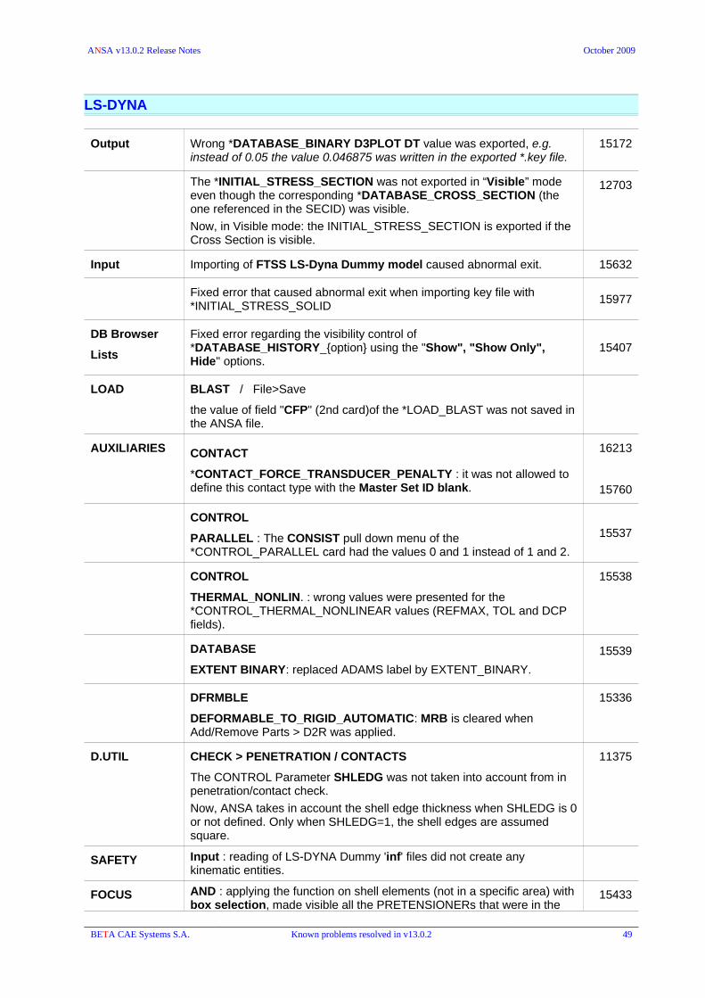
ANSA v13.0.2 Release Notes October 2009
LS-DYNA
Output Wrong *DATABASE_BINARY D3PLOT DT value was exported, e.g. instead of 0.05 the value 0.046875 was written in the exported *.key file.
15172
The *INITIAL_STRESS_SECTION was not exported in “Visible” mode even though the corresponding *DATABASE_CROSS_SECTION (the one referenced in the SECID) was visible.
Now, in Visible mode: the INITIAL_STRESS_SECTION is exported if the Cross Section is visible.
12703
Input Importing of FTSS LS-Dyna Dummy model caused abnormal exit. 15632
Fixed error that caused abnormal exit when importing key file with *INITIAL_STRESS_SOLID
15977
DB Browser
Lists
Fixed error regarding the visibility control of *DATABASE_HISTORY_{option} using the "Show", "Show Only", Hide" options.
15407
LOAD BLAST / File>Save
the value of field "CFP" (2nd card)of the *LOAD_BLAST was not saved in the ANSA file.
AUXILIARIES CONTACT
*CONTACT_FORCE_TRANSDUCER_PENALTY : it was not allowed to define this contact type with the Master Set ID blank.
16213
15760
CONTROL
PARALLEL : The CONSIST pull down menu of the *CONTROL_PARALLEL card had the values 0 and 1 instead of 1 and 2.
15537
CONTROL
THERMAL_NONLIN. : wrong values were presented for the *CONTROL_THERMAL_NONLINEAR values (REFMAX, TOL and DCP fields).
15538
DATABASE
EXTENT BINARY: replaced ADAMS label by EXTENT_BINARY.
15539
DFRMBLE
DEFORMABLE_TO_RIGID_AUTOMATIC: MRB is cleared when Add/Remove Parts > D2R was applied.
15336
D.UTIL CHECK > PENETRATION / CONTACTS
The CONTROL Parameter SHLEDG was not taken into account from in penetration/contact check.
Now, ANSA takes in account the shell edge thickness when SHLEDG is 0 or not defined. Only when SHLEDG=1, the shell edges are assumed square.
11375
SAFETY Input : reading of LS-DYNA Dummy 'inf' files did not create any kinematic entities.
FOCUS AND : applying the function on shell elements (not in a specific area) with box selection, made visible all the PRETENSIONERs that were in the
15433
BETA CAE Systems S.A. Known problems resolved in v13.0.2 49

ANSA v13.0.2 Release Notes October 2009
current model.
PAM-CRASH
Input / Output CNTAC: Contact type 36 > "IEDGE" field was ignored.
Moreover, the following changes now, for :INPUTVERSION <=2003 : IEDGE parameter format is I5INPUTVERSION >=2004 : IEDGE parameter format is I10INPUTVERSION >=2006 : NACC, NUMBKT and THKEXT are not exported.
15288
Input fix reading of values:
ECTRL: RATESCALE & RATEFILTER and
OCTRL: RSTOUTPUT
15085
Input Fixed error regarding interpretation of Materials : could not create the five blanks after CURVE keyword.
15194
Output SUBSTRUCTURE
RBODYs were written wrongly in the Substructure Group as elements.
13433
CONSTRAINTs RWALL> Set : the selection of empty set is not allowed now. 15253
D.UTIL D.INFO
Wrong mass calculation of shells assigned materials 130, 131 and 132. The information (mass density, thickness) defined in the PLY data was ignored.
15702
CHECK>PENETRATION / CONTACTS : did not take into account the PLY thickness (sum of PLY thickness) when hcont<0.
(For elements assigned materials 130, 131 or 132 )
15699
SET "Modify Contents" did not display the category CONSTRAINTs 16069
Materials Material 200 (bar/beam null material): E=0 for is now allowed. 16308
Materials / PLY Materials 130, 131 and 132 are considered invalid if they don't have at least one PLY definition.
PLY : The fields "E11","E22"", "E33", "G12", "G23" and "G13" can not be blank, zero or negative. Must be > 0.
The aforementioned cases are detected by CHECK>MODEL DATA.
15704
CONNECTORs For current Deck module Pam-Crash, the “Interface-i” RBE2 creates now Rbody type 0 with the exact definition of Pam Crash. The NCOG is auto-defined by the Apply and not during the output to Pam-Crash.
10129
BETA CAE Systems S.A. Known problems resolved in v13.0.2 50

ANSA v13.0.2 Release Notes October 2009
BETA CAE Systems S.A. Known problems resolved in v13.0.2 51

ANSA v13.0.2 Release Notes October 2009
RADIOSS
Input In imported files with TH/PART , thePART was interpreted only as PROP/SHELL. Therefore references to PROP/SPRING or PROP/BEAM was not read correctly.
16043
TIME HISTORY
It was, wrongly, not allowed to create TH/PART by using /PROP/SPRING/
16050
ANSYS
Output Fixed problem with beam-pipe elements
the field 9 of EBLOCK command should be the number of nodes defining this element. ANSA exported these elements with field 9 equal to zero.
15116
Output Unused (needless) node sets were exported when having solid facets sets used by contacts.
15302
Database Browser / Lists
Could not filter by “Advanced Filter” for "TETRAHEDRAL" element type in ANSYS deck.
16065
Properties Property BEAM188
When switching to BEAM188 type in corresponding property card the MID field was not available and so it was not possible to define material for this type.
15299
MEDINA
Input Fixed ANSA - MEDINA Transformation Matrix relation (A - A transpose).
Nastran input file with CWELDS of type ALIGN, GRIDID and ELEMID did not properly converted into MEDINA
Note that 'CWELD, GRIDID' cannot be converted since MEDINA does not support this CWELD type.
15558
Fixed creation of two ANSA_Parts with the same name after importing two medina files one after the other.
16482
BETA CAE Systems S.A. Known problems resolved in v13.0.2 52

ANSA v13.0.2 Release Notes October 2009
CFD++
Output CFD++ output problems related to the type of entities within the ansa file i.e. FE-model mesh or Macros mesh and ANSA Volumes mesh
(in v13.0.0)
13588
OpenFOAM
Output boundary file did not specify number of patches 16196
Input Fixed wrong interpretation of ':' character in BC name 15175
SOLVER INFO Informative message is now printed in case of invalid combinations in General Tab.
15086
UH3D
Input Fixed error caused abnormal exit when importing UH3D file with invalid property reference.
16431
STAR CD / STAR CCM
StarCCM : surface mesh of baffles did not have uniform orientation in output. This error is fixed.
16221
FLUENT
Input Fixed double precision syntax input problem of Fluent .cas binary file format.
BETA CAE Systems S.A. Known problems resolved in v13.0.2 53
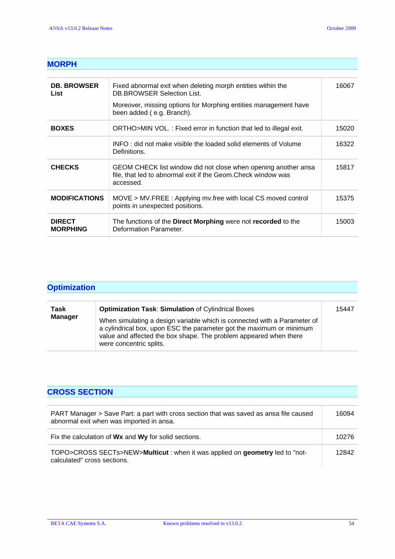
ANSA v13.0.2 Release Notes October 2009
MORPH
DB. BROWSER List
Fixed abnormal exit when deleting morph entities within the DB.BROWSER Selection List.
Moreover, missing options for Morphing entities management have been added ( e.g. Branch).
16067
BOXES ORTHO>MIN VOL. : Fixed error in function that led to illegal exit. 15020
INFO : did not make visible the loaded solid elements of Volume Definitions.
16322
CHECKS GEOM CHECK list window did not close when opening another ansa file, that led to abnormal exit if the Geom.Check window was accessed.
15817
MODIFICATIONS MOVE > MV.FREE : Applying mv.free with local CS moved control points in unexpected positions.
15375
DIRECT MORPHING
The functions of the Direct Morphing were not recorded to the Deformation Parameter.
15003
Optimization
Task Manager
Optimization Task: Simulation of Cylindrical Boxes
When simulating a design variable which is connected with a Parameter of a cylindrical box, upon ESC the parameter got the maximum or minimum value and affected the box shape. The problem appeared when there were concentric splits.
15447
CROSS SECTION
PART Manager > Save Part: a part with cross section that was saved as ansa file caused abnormal exit when was imported in ansa.
16094
Fix the calculation of Wx and Wy for solid sections. 10276
TOPO>CROSS SECTs>NEW>Multicut : when it was applied on geometry led to "not-calculated" cross sections.
12842
BETA CAE Systems S.A. Known problems resolved in v13.0.2 54

ANSA v13.0.2 Release Notes October 2009
SCRIPTING
SystemOutput command didn't work on Windows platforms 15163
Misleading help file lead to crash when the TOPO_GEOMETRY_TRANSFORM() was used in scripts.
16357
Fixed MERGE from script when filename contains blanks
ANSA crashed when after the batchmesh scenario the WriteStatistics() was called via script
15693
PrintToFile functions didn't work as expected when opening a file with the
'-i' and '-exec' flags.
15198
15221
Fixed problem with the PrintToFile script function 15152-ii
fix script function OutputOpenFoamPoints when mode == visible or mode == model.
Added an extra argument in OutputOpenFoamPoints "Scale" as regular output does.
CollectEntities fixed and enhanced behavior 15304
Fixed script function MESH_PERIMETERs_FL2CURV.
The entered value didn't affect the result.
The current feature line angle value was used instead.
14393
NodesToElements : fixed the wrong result with 2nd order elements
The function used to returned the element twice when the 3rd node of a 2nd order tria was given as input.
12073
WriteStatistics returned 1 although the meshing scenario was completed
Return value problem is fixed. Status of scenario wasn't informed after run.
15974
Fixed error that caused abnormal exit when importing script, if not having any script already loaded.
15975
'Use Thickness to Diameter map' didn't work when a script function was given in ANSA.defaults (v13.0.1)
15615
Fixes for :
GetNewSession/GetNewLayersSession/GetNewVolumeSession:
AddSessionToMeshingScenario:
DeleteEntity:
CreateEntityVa : Could not create HOURGLASS or DEFINE_SD_ORIENTATION, or DEFINE_VECTOR, SENSOR undefined through scripting at once.
16385
BETA CAE Systems S.A. Known problems resolved in v13.0.2 55

May, 2009
Release Notes
v13.0.1

BETA CAE Systems S.A.
Kato Scholari, Thessaloniki
GR-575 00 EpanomiGreece
Tel. : +30-2392021420Fax. : +30-2392021417
http://www.beta-cae.gr
Queries & Services : [email protected]
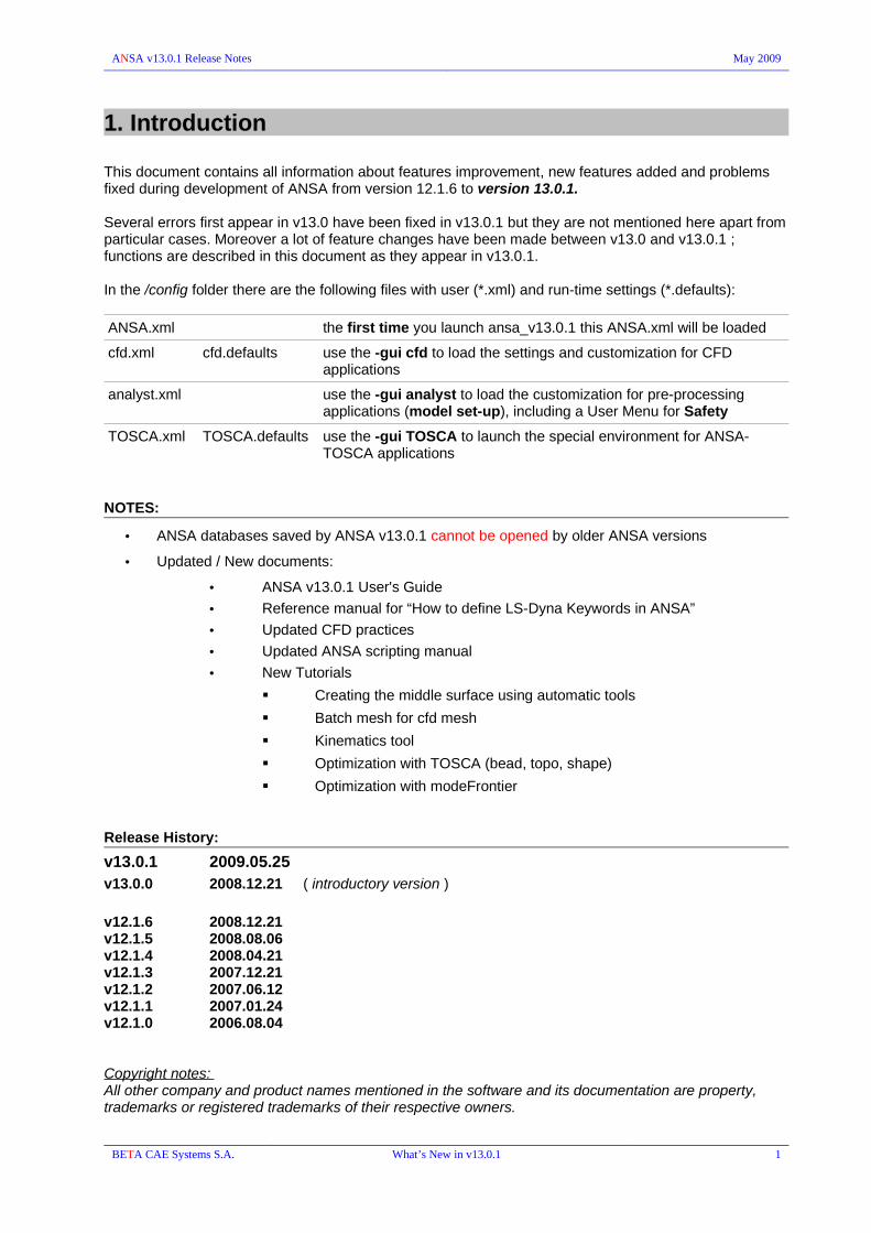
ANSA v13.0.1 Release Notes May 2009
1. Introduction
This document contains all information about features improvement, new features added and problems fixed during development of ANSA from version 12.1.6 to version 13.0.1.
Several errors first appear in v13.0 have been fixed in v13.0.1 but they are not mentioned here apart from particular cases. Moreover a lot of feature changes have been made between v13.0 and v13.0.1 ; functions are described in this document as they appear in v13.0.1.
In the /config folder there are the following files with user (*.xml) and run-time settings (*.defaults):
ANSA.xml the first time you launch ansa_v13.0.1 this ANSA.xml will be loaded
cfd.xml cfd.defaults use the -gui cfd to load the settings and customization for CFD applications
analyst.xml use the -gui analyst to load the customization for pre-processing applications (model set-up), including a User Menu for Safety
TOSCA.xml TOSCA.defaults use the -gui TOSCA to launch the special environment for ANSA-TOSCA applications
NOTES:
• ANSA databases saved by ANSA v13.0.1 cannot be opened by older ANSA versions
• Updated / New documents:
• ANSA v13.0.1 User's Guide
• Reference manual for “How to define LS-Dyna Keywords in ANSA”
• Updated CFD practices
• Updated ANSA scripting manual
• New Tutorials
Creating the middle surface using automatic tools
Batch mesh for cfd mesh
Kinematics tool
Optimization with TOSCA (bead, topo, shape)
Optimization with modeFrontier
Release History:
v13.0.1 2009.05.25v13.0.0 2008.12.21 ( introductory version )
v12.1.6 2008.12.21v12.1.5 2008.08.06v12.1.4 2008.04.21v12.1.3 2007.12.21v12.1.2 2007.06.12v12.1.1 2007.01.24v12.1.0 2006.08.04
Copyright notes: All other company and product names mentioned in the software and its documentation are property, trademarks or registered trademarks of their respective owners.
BETA CAE Systems S.A. What’s New in v13.0.1 1

ANSA v13.0.1 Release Notes May 2009
2. What’s new in v13.0.1Enhancements – New Options – New Features
GENERAL
A new Graphic User Interface with many new menu and layout customization options:
a short description of the new layout:
1.Main pull down menus
9.Database Browser
10.Status Bar
6.General Buttons
2.Toolbars
3.Module Buttons
4.Module Buttons Group
5.Hidden Buttons pop-up
7.Ansa Info8.Command Line
Hidden Window
BETA CAE Systems S.A. What’s New in v13.0.1 2

ANSA v13.0.1 Release Notes May 2009
Launching When ANSA v13.0.1 is launched searches (to read) the ANSA.defaults , ANSA.xml and ANSA_TRANSL within the folder:
for unix
/home/user/.BETA/ANSA/version_13.0.1/
instead of the user's home directory
for windows
C:\Documents and Settings\user\.BETA\ANSA\version_13.0.1\
that will be automatically created the first time ANSA will be launched.
Apart from the .BETA folder ANSA.defaults and ANSA_TRANSL are read in also from the ANSA_HOME and the current directory.
All settings that used to be saved within the ANSA.defaults that were related to user layout (buttons, colors, fonts, etc) are obsolete since all these settings are now stored within the ANSA.xml
The ANSA.xml file has all the user settings regarding the buttons location, menus configuration, colors, fonts, window style, windows size and location, filters, list windows configuration. The ANSA.defaults file hosts all the functions' configuration like mesh parameters, morphing, topology settings, etc.
ANSA.xml can imported in an open ANSA or can be auto-read by any location using the -xml starting option.
Moreover, you can start ANSA with the -gui option and as a second option give a <name> that corresponds to name.defaults and name.xml, e.g.
ansa.sh -gui cfd
will start ANSA that will read the cfd.defaults and cfd.xml which are placed into the /home/user/.BETA/ANSA/version_13.0.1/
or the ANSA_HOME directory.
Windows All List windows and Module Buttons windows can be docked, e.g. on left/right or bottom side of the main ANSA window in order to have more clear graphic area.
The windows can be tabbed in other docked windows.
A preview is given when a window is docked or placed as tab – using drag and drop.
Expand the size of a window by moving the mouse towards the side to be expanded holding down the “middle mouse button” and the “Shift” key. This is not available for tree-form list windows, i.e SETs
Click with middle mouse on the title bar of a floating window in order to “roll it up” . (the window is minimized to its title bar)
Columns in List windows can be added by using the new tool List Fields that provides all the edit card's fields of the listed items.
Menus The bottom menu called General Buttons is available in any Module Menu in order to reduce menu changes. All General buttons can be used despite the currently active Module. For instance the REALIZE button that launches the Connection Manager is available also when a Deck menu is active.
All Module Menus (TOPO, MESH, MORPH, DECKs, etc.) as well as the General Buttons can be docked or tabbed.
Buttons of each Group of Module buttons can be easily placed in a position or in the Hidden window by drag and drop. The Hidden buttons pop-up window easily accessed by the arrow next to the Group's name.
BETA CAE Systems S.A. What’s New in v13.0.1 3

ANSA v13.0.1 Release Notes May 2009
The Hidden window opens by right-click onto Module Buttons group label. Functions of an open Hidden window can be used in any Module menu, e.g. The Hidden window of MESH>SHELL MESH can be used while the Deck>NASTRAN Module is active.
A Group of buttons in each menu (Module/General) may be removed or added group
User Menu A custom made menu can be created by “drag and drop” Module buttons, Group of buttons from any module, including the buttons that are created by script. User Menu and Groups of buttons within it, can be given any custom name.
To create such a menu go to Modules>Create Menu. The edit mode is activated ; during this mode only custom user menu definition is allowed.
In the field next to the Add Group button enter an appropriate name for the first group of functions that is going to be created, and press Add Group.
The Deck Mode specifies the deck module that can be used as source of deck buttons.
The Draw mode specifies the style of the displayed Faces/Macro Areas.
Using drag and drop with the middle mouse button, pick buttons from any module buttons group, to place them in the group of the User Menu. A whole module buttons group can be placed in the User Menu, by picking it with the middle mouse button from the label of the group.
Tooltip balloons indicate the origin path of the button that is placed in the User Menu.
Delete a button from a group by pressing the Ctrl key and the right click on the button. Once a group is empty from buttons the user can delete it, by clicking with the right mouse button onto its label while pressing the Ctrl key.
Press Finished to confirm the custom menu definition. The new menu is available as a Module Buttons menu.
To edit an already created user defined menu, one have to activate it and then by right clicking on its title bar select 'Edit Mode'. To delete a user defined menu, right clicking on its title bar and select 'Delete Menu'.
BETA CAE Systems S.A. What’s New in v13.0.1 4

ANSA v13.0.1 Release Notes May 2009
Shortcuts Any button can be assigned to a keyboard shortcut combination with Shift, Ctrl or Alt keys
Buttons defined by scripts can be also called by a shortcut key.
The toggle buttons (switch) of the Selection and Drawing modes (ENT, PID, MID, ..) can be changed (switch between options) using a shortcut.
Shortcuts are defined by the Windows>Options>GUI Settings>Buttons Manager
140
Windows > Options
The Windows>Options enable the Options - Buttons Manager window that gives access to “Functional preferences” and “Menu/Layout configuration”.
The options that are related to Functions preferences are listed under the Settings section (mainly hosts the former SETTINGS>SETTINGS menu). They are saved in ANSA.defaults
The options that are related to menu, layout and user interface customization are listed under the GUI Settings. They are saved in ANSA.xml.
BETA CAE Systems S.A. What’s New in v13.0.1 5

ANSA v13.0.1 Release Notes May 2009
GUI Settings
Menus and Windows:
- specify the Window style
- customize the number of Rows and Columns for buttons for the Module Buttons , General Buttons and User Script buttons menus.
- configure the drawing (size and position) of the Axes for the Global Coordinate system
- Enable/disable Tooltips for Module buttons and Docking for windows.
Colors:
- customize colors and enable Gradient style for the main drawing area
- choose colors for the Layout (buttons, windows, menus, etc)
- handle Front and Back color for Faces, elements, etc (ENT drawing mode)
- enable the different color between lines in List windows.
Fonts:
- choose font type and size for OpenGL , Windows and Menus
Toolbar Manager:
- handle visibility, icons, labels, etc of buttons in toolbar
Buttons Manager:
- control visibility for main toolbar functions
- customize the default action of the drop menu (the first option of the menu which is also enabled with single click on the button)
- define Shortcut keys for functions
BETA CAE Systems S.A. What’s New in v13.0.1 6

ANSA v13.0.1 Release Notes May 2009
- assign icons for buttons
- modify button's tooltip and label
!!! with Ctrl+middle_click onto a button opens the Buttons Manager directly for this button configuration.
Due to the fact that all user preferences regarding layout, menus, function pull down menus options, etc are stored in ANSA.xml, these particular settings are obsolete from older ANSA.defaults (where they used to be stored).
SELECTIONS Area selection : new window with icon-buttons that can be docked on the toolbar menu.
new selection types:
Macro Area : the entire Macro Area is selected with single click. Box selection selects Macro Areas as well.
PID Region : single click selects elements that define a region of the currently visible and connected shells of the same property. The selection stops at blue bounds (common edge for more than two elements).
Feature Line : new window with icon-buttons that can be docked on the toolbar menu.
PID Neighbs : new selection type that with single click selects line elements (e.g. beams) that are currently visible and connected.
The Feature Area selection has been added in several functions like the TOPO>FACEs>[SET PID] , the Geometry>DELETE or the DECK>ELEMENTs>DELETE.
784
Exiting Codes
ANSA returns the following exiting codes:
0 : normal exit
-1 : licensing related error (no available credits, communication error, etc)
other than 0 or -1 : abnormal exit
BETA CAE Systems S.A. What’s New in v13.0.1 7

ANSA v13.0.1 Release Notes May 2009
Database Browser
Database Browser
Windows>Database
A new database browser window that can be docked and remain active along with any function.
The browser provides a tree formed list and list management windows for all entities of the loaded database controlling also their visibility as it used by the F12 window.
The Include Manager and the applied Advanced Filters (of any list) can be accessed via the Database function.
As soon as the user selects one group of entities, the respective Selection window appears, which can also be docked. In order to open the Selection list for the first time double click on the entity in the tree-form list.
Moreover, the list of Reference entities appear as Tab in the Database browser.
Right click on a group of entities provides a drop menu with on-screen control functions (Show, Hide, Show Only) as well as to Open or Open in New Tab in order to launch a list with these entities.
Entities visibility control
The visibility of all entities by means of their drawing is now controlled by the Database browser. The “Deck Parameters” window that was launched by the F12 is removed. The F12 key now launches the Browser if this is not already open.
The display control is achieved by the check boxes under the Visible column.
Right click on the header label [Visible] activates the menu with the options All, None, Invert, Lock
The check box of the Group of entities (e.g. ELEMENTs) controls all “child” items. It also “remembers” the status of the 'child' items since the last time.
If there is at least one 'child' item not enabled the Group's check box is faded.
13223
13183
BETA CAE Systems S.A. What’s New in v13.0.1 8

ANSA v13.0.1 Release Notes May 2009
Filter window
In the Filters window all the applied filters that have been produced from the advanced filtering in the lists, are saved and remain available for future use and editing.
The filters are categorized according to the type of entity that had been applied to. In this window a right click menu is available either for a group of filters or for each filter separately. In this menu, visibility commands are available, edit and delete actions, plus evaluation actions.
By selecting 'Evaluate', 'Re-Evaluate' and 'Evaluate All', you can apply the filters and see how many entities satisfy its rules.
All the filters in the Filters window are saved when ANSA quits in the ANSA.xml file, and are available for future use.
Clicking on a filter opens the respective list (displayed in the Selection window).
By clicking on a filter and dragging it, for example on an include, all entities that satisfy this filter are dragged and dropped into the include.
The right click drop menu for Filters:
Multiple selections are also allowed.
The Filters of a group can be edited with right click onto the group name.
BETA CAE Systems S.A. What’s New in v13.0.1 9
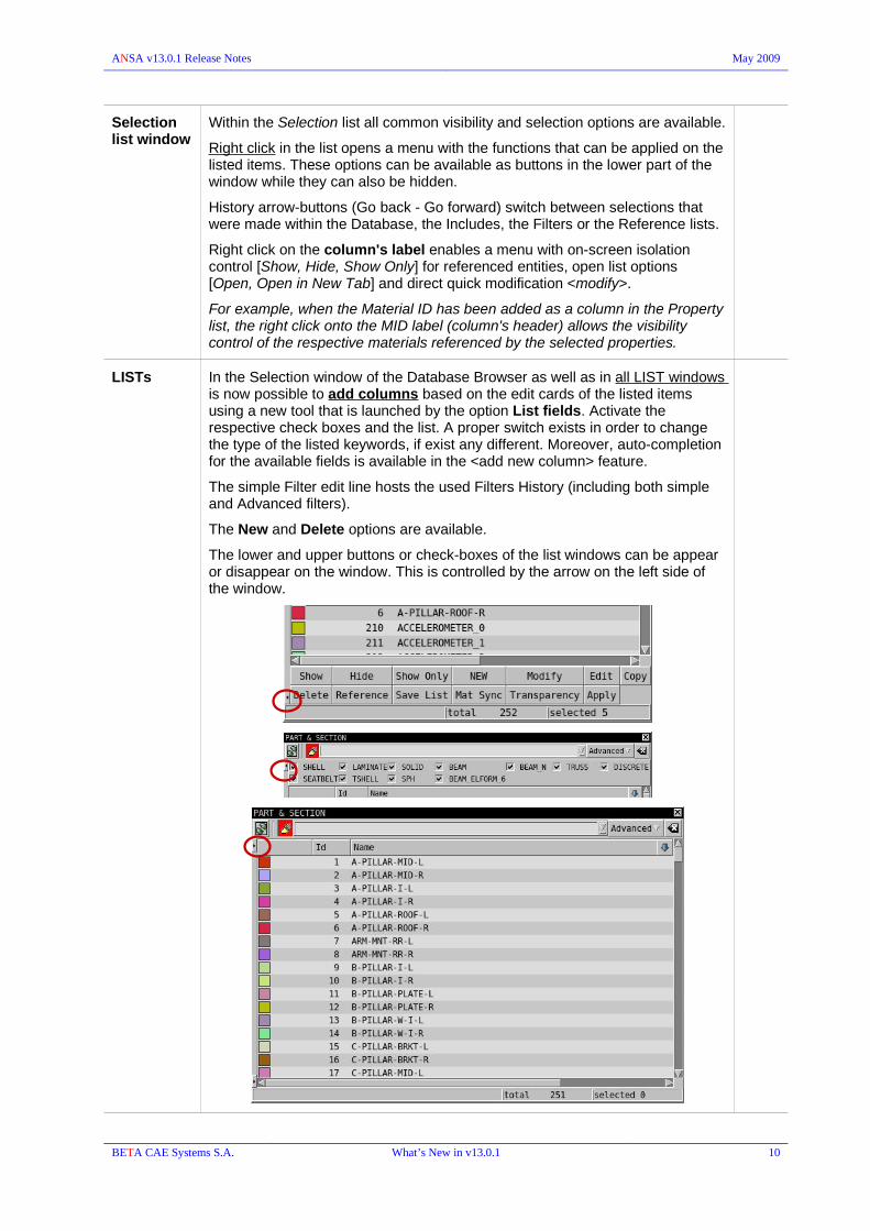
ANSA v13.0.1 Release Notes May 2009
Selection list window
Within the Selection list all common visibility and selection options are available.
Right click in the list opens a menu with the functions that can be applied on the listed items. These options can be available as buttons in the lower part of the window while they can also be hidden.
History arrow-buttons (Go back - Go forward) switch between selections that were made within the Database, the Includes, the Filters or the Reference lists.
Right click on the column's label enables a menu with on-screen isolation control [Show, Hide, Show Only] for referenced entities, open list options [Open, Open in New Tab] and direct quick modification <modify>.
For example, when the Material ID has been added as a column in the Property list, the right click onto the MID label (column's header) allows the visibility control of the respective materials referenced by the selected properties.
LISTs In the Selection window of the Database Browser as well as in all LIST windows is now possible to add columns based on the edit cards of the listed items using a new tool that is launched by the option List fields. Activate the respective check boxes and the list. A proper switch exists in order to change the type of the listed keywords, if exist any different. Moreover, auto-completion for the available fields is available in the <add new column> feature.
The simple Filter edit line hosts the used Filters History (including both simple and Advanced filters).
The New and Delete options are available.
The lower and upper buttons or check-boxes of the list windows can be appear or disappear on the window. This is controlled by the arrow on the left side of the window.
BETA CAE Systems S.A. What’s New in v13.0.1 10

ANSA v13.0.1 Release Notes May 2009
Filter in Lists
For the Database Browser's Selection list and all LIST windows:
- The filter field hosts the history of the used simple filters and advanced filters.
- user is able to filter based on the field of the listed items' edit cards. Auto-completion/suggestion of the field label is provided.
- filter type "Expression" is now available also for the simple filter. Type "Expression:" in the simple filter line followed by an expression (for example in a property card check if the MID1 is greater than 2: @MID1@>2, or reference a field from another card: @MID1@->@NU@==0.3 etc.).
- The user may omit to type "Expression:" and type right away an expression. The filter will be interpreted as an expression as long as it starts with a @ and the first field (the value between the first two @) is one of the columns in the list.
BETA CAE Systems S.A. What’s New in v13.0.1 11

ANSA v13.0.1 Release Notes May 2009
Modify massive modifications can be performed:
• quick <modify> directly on a field that appears as a column; right click on the field's label header and type the new value that will be applied to the field of the selected items
• Advanced Modify: right click in the list and choose the Modify option (former EFM>Modify tool) to enable the dialog box for the modification of more that one fields in one shot.
The expressions and language of the EFM tool (Edit-Filtering-Modify) , like $, COUNTER are still valid.
Modify can handle Name and Comment fields (strings) with no need to close the string in double quotes " " in case of simple cases, e.g. substitute all the name with a new name or add a comment in a blank field. In complicated cases where special characters are used the double quotes are needed.
If any entity failed the modification process, an option is given to have a list shown with these entities.
The box that hosts the fields “to be modified” can store the input fields. Moreover, is able to auto-complete the name or suggest possible options of the field, for easier input.
The last used “Modify Rules” for each entity type are preserved during the ANSA session and are saved in the ANSA.xml for future use.
BETA CAE Systems S.A. What’s New in v13.0.1 12

ANSA v13.0.1 Release Notes May 2009
Filtering Advance filters:
New interface:
The box that hosts the field that is used for the filtering stores previously used fields and auto-completes the name of the input field (providing also potential field labels)
While the Apply button isolates in the List only the items that fulfill the given filtering criteria the Select button selects only these items without removing the other items from the List.
New filtering types:
- "Expression": type an expression using the EFM language, for example in a property card check if the MID1 is greater than 2: @MID1@>2, or reference a field from another card: @MID1@->@NU@==0.3 etc.
- "use filter". A filter is able to use another filter. Select two or more existing filters and create a new filter that uses the selected filters, either matching All or Any of them. Mind that when a filter references a filter that is absent, the check always returns true (pass) for the absent filter.
The name of an Advanced filter is automatically added in the history of the used filters accessed by the simple filter of List.
BETA CAE Systems S.A. What’s New in v13.0.1 13

ANSA v13.0.1 Release Notes May 2009
Besides the method through the Filter Rules and Modify Rules windows there is the option to choose the fields to be filtered or modified through the edit card of the listed entities that accessed by the “Open Card” button.
The “edit” card is available only for the type but not for the group, i.e for Shell Properties or Beam Properties but Not for All Properties.
The card of the respective (selected) entities opens. Enable the label of the field and type the filtering or modification expression and thus perform the filtering/modification directly in this card, without creating filtering or modification rules by adding fields.
BETA CAE Systems S.A. What’s New in v13.0.1 14

ANSA v13.0.1 Release Notes May 2009
File> Open
STEP
Transformation matrices, Hierarchy, Property Name & Thickness, Part's module-id and Product version are well interpreted and imported into ANSA.
Properties are created based on Layer, Color or Body
IGES
Property Thickness is imported form IGES files that have been exported by ANSA.
13855
The Windows>Options>Settings>CAD Input topology
gives access to the preferences for the reading of CAD data such as *.iges, *.step, *.vda-fs
The check box 'GEOMETRY CLEAN UP' is disabled by default.
After the reading of the CAD data a message in the Ansa Info window reporting the preferences used for the interpretation.
13415
IGES & STEP input: in case of imported problematic face definition on periodic surfaces, these faces are detected and are replaced by untrimmed faces. Curves that describe the actual bounds of these problematic faces are created. In order to be easily isolated (face with its curve bounds) they are grouped into sets (DECKs menu) with the prefix "untrimmed_periodical_face_with_bound_curves".
3814
9876
9944
File> Output CAD
STEP : Improved interpretation to STEP format. Parts Hierarchy, Property Name and Property Thickness are supported. Properties (PID) are translated into Layers.
IGES : Property Thickness can be exported.
BETA CAE Systems S.A. What’s New in v13.0.1 15

ANSA v13.0.1 Release Notes May 2009
File> Compress
The function includes the former FILE>COMPRESS and the DECK>CLEAR capabilities.
Provides a preview of detected unused entities in a tree list for ALL entities: F.E. , Geometry, ANSA Parts/Groups.
The activated check boxes for each entity enable their deletion. The check box for the “parent” level entity eg. F.E. Affects all the “child” items.
The [ Details ] button enables the preview of the detected unused entities and allows control and further selection/deselection of the “entities that will be removed”.
The “In List” column shows the number of the detected items that could be removed. The “To Compress” column shows the number of entities that will be finally removed.
974
BETA CAE Systems S.A. What’s New in v13.0.1 16
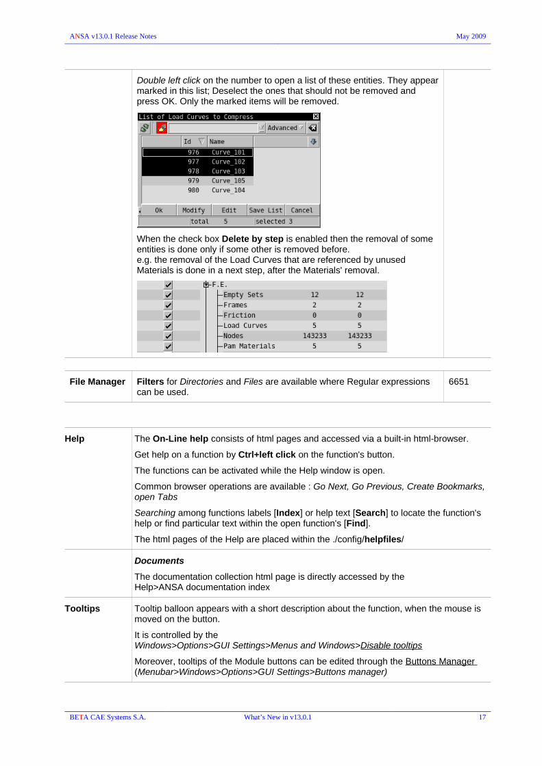
ANSA v13.0.1 Release Notes May 2009
Double left click on the number to open a list of these entities. They appear marked in this list; Deselect the ones that should not be removed and press OK. Only the marked items will be removed.
When the check box Delete by step is enabled then the removal of some entities is done only if some other is removed before.e.g. the removal of the Load Curves that are referenced by unused Materials is done in a next step, after the Materials' removal.
File Manager Filters for Directories and Files are available where Regular expressions can be used.
6651
Help The On-Line help consists of html pages and accessed via a built-in html-browser.
Get help on a function by Ctrl+left click on the function's button.
The functions can be activated while the Help window is open.
Common browser operations are available : Go Next, Go Previous, Create Bookmarks, open Tabs
Searching among functions labels [Index] or help text [Search] to locate the function's help or find particular text within the open function's [Find].
The html pages of the Help are placed within the ./config/helpfiles/
Documents
The documentation collection html page is directly accessed by the Help>ANSA documentation index
Tooltips Tooltip balloon appears with a short description about the function, when the mouse is moved on the button.
It is controlled by the Windows>Options>GUI Settings>Menus and Windows>Disable tooltips
Moreover, tooltips of the Module buttons can be edited through the Buttons Manager (Menubar>Windows>Options>GUI Settings>Buttons manager)
BETA CAE Systems S.A. What’s New in v13.0.1 17
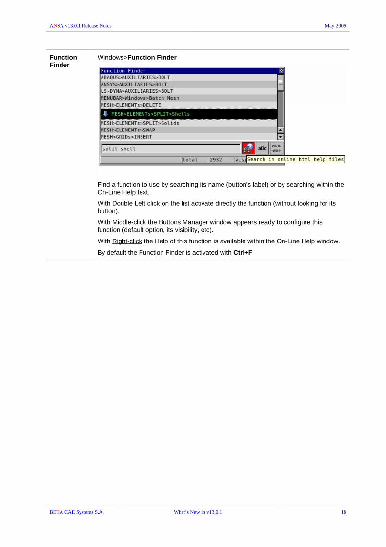
ANSA v13.0.1 Release Notes May 2009
Function Finder
Windows>Function Finder
Find a function to use by searching its name (button's label) or by searching within the On-Line Help text.
With Double Left click on the list activate directly the function (without looking for its button).
With Middle-click the Buttons Manager window appears ready to configure this function (default option, its visibility, etc).
With Right-click the Help of this function is available within the On-Line Help window.
By default the Function Finder is activated with Ctrl+F
BETA CAE Systems S.A. What’s New in v13.0.1 18

ANSA v13.0.1 Release Notes May 2009
Display F11 : Quality Criteria – Presentation parameters window
Detail on Demand : This display control feature has been added in the Presentation Parameters tab of the F11 window.
Provides a gradual increase of detail for the model, which will depend on the current view. Such a “detail on demand” effect can be obtained by adjusting the respective regulator.
The more the user zooms in, the more details of the model come to visible, leading in a more detailed view of the model.
The detail on demand effect affects, first of all the visibility of the mesh in a model. By zooming out, the wire is lost equivalently to the view with the WIRE flag off. In this case in order to indicate the existence of mesh on Macro Areas, small dot are displayed in the middle of the shells.
The righter the regulator is, the more intense is the effect, which means that less zoom out is needed for the details disappear.
BETA CAE Systems S.A. What’s New in v13.0.1 19

ANSA v13.0.1 Release Notes May 2009
Graph Parameters
The settings in this tab control the color view modes:
EL.THICK , EL.NSM, EL.PRESS , EL.TEMP , C.THICK , M.SCALE, QGRAPH , SGRAPH
Besides the Q.Graph and S.Graph sections that refer to the respective color view modes, generally:
Color Bar Limits
select the limits of the color bar, by choosing one of the following three options:
Whole DB: Auto adjust range from all shell elements of the Database
Visible: Auto adjust range from Visible shell elements only
User min-max: Specify user defined min and max values in the two activated fields
Ranges defined min-max: used only for the Q.GRAPH color view mode
Color Bar Colors
select the way the color bar will be configured, by choosing one of the following two options:
Palette: Specify the number of classes (colors). Each color can be configured by pressing on the sample square.
Unique color: Assign a unique color for each class of thickness.
Use unique color for each range : used only for the Q.GRAPH color mode
The “Color Bar Limits” and the “Color Bar Colors” options can be combined according the user's needs.
BETA CAE Systems S.A. What’s New in v13.0.1 20
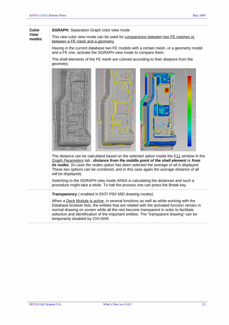
ANSA v13.0.1 Release Notes May 2009
Color View modes
SGRAPH: Separation Graph color view mode
This new color view mode can be used for comparisons between two FE meshes or between a FE mesh and a geometry.
Having in the current database two FE models with a certain mesh, or a geometry model and a FE one, activate the SGRAPH view mode to compare them.
The shell elements of the FE mesh are colored according to their distance from the geometry.
The distance can be calculated based on the selected option inside the F11 window in the Graph Parameters tab : distance from the middle point of the shell element or from its nodes. (In case the nodes option has been selected the average of all is displayed. These two options can be combined, and in this case again the average distance of all will be displayed).
Switching to the SGRAPH view mode ANSA is calculating the distances and such a procedure might take a while. To halt the process one can press the Break key.
Transparency ( enabled in ENT/ PID/ MID drawing modes)
When a Deck Module is active, in several functions as well as while working with the Database browser lists, the entities that are related with the activated function remain in normal drawing on screen while all the rest become transparent in order to facilitate selection and identification of the important entities. The “transparent drawing” can be temporarily disabled by Ctrl+Shift.
BETA CAE Systems S.A. What’s New in v13.0.1 21

ANSA v13.0.1 Release Notes May 2009
General Buttons: The bottom menu contains group of buttons which are available along with any activated Module. They can also be added in a User Menu.
FOCUS ISOLATE : the pull down menu is reorganized and new functions added.
FLANGES
• PROXIMITY : locates potential flanges based on the following recognition parameters
• LINK : locates group of parent and child Linked Faces
• SHAPE : detects candidate flange areas on each part
• CONNECTIONS : new option to locate flanges based on a search distance detection and the existence of connections on them.
RADIUS
HOLE ZONES: new function to locate element zones around holes
SKIN: this is the former OUTER/INNER function that isolates the outer or inner faces of a solid description or a complex assembly
TUBES: the function is now able to detect tubes taking into account Solid elements' Facets and FEM shell elements. A new option has been added to create a center line of the tube.
BAFFLES: new function to locate the “thin-wall” structures
SHORT PATH: indicates the shortest path between two elements (this function used to be the ELEMENTs> WRAP [Short Path] )
BOUNDS > SINGLE || TRIPLE || SPURS :isolates all neighboring elements to single and triple boundaries as well as those with irregular connection to their neighbors. (The function applies on FE-model elements only)
9776
BEST : After the selection of 3 points, the model is transformed so that the vector defined by the first two selected points turns parallel to the x-axis of the screen.
6498
OR – NOT : the functions affect FEM entities with no property also in PID selection mode
BETA CAE Systems S.A. What’s New in v13.0.1 22

ANSA v13.0.1 Release Notes May 2009
OR with PID selection mode : using box selection in empty space clears the screen
12780
OR – NOT – AND - !NOT in ENT selection mode : with double click (left or right) the selection is performed as if it was in PID mode.
D.UTIL The group hosts the Deck Utility functions :
D.INFO : deck report
CHECK : detect errors and verify model's integrity
VISIB BOUNDS : The Boundary drawing style is enabled for FE entities not related to Geometry also when in TOPO Module menu.
9921
W.SPOTS This group contains the following functions that used to be in the TOPO>WELD SPOTs group:
REALIZE: activates the Connections Manager
ERASE: removes connections via the Connections Selection Assistant
RM.DBL. : detects double defined connections within a given distance with the option to combine their information to the remaining ones.
GEOMETRY : The group contains the TRANSF. , DELETE , FINE , and MEASURE functions
MEASURE
Enhanced functionality that enable numerous measurement options:
Node position, Distance, Length, C.O.G. , Angle, Polyline, Curvature, Area, Volume, Middle Point, Inscribed Circle, Circumscribed Circle, Equivalent Circle.
2917
2396
10512
11883
BETA CAE Systems S.A. What’s New in v13.0.1 23

ANSA v13.0.1 Release Notes May 2009
User is able to, simultaneously, measure multiple quantities between groups of different kinds of entities. For example, the user can consecutively select nodes, edges, shells or solids and watch the real-time alteration of the potential measuring results. The latter are displayed via a pull-down menu in the main Measure window and, therefore, the user has a full overview, in order to conclude to the final combined measurement result.
Note the ability to switch between different selection modes using the "1" key in the alphanumeric section of the keyboard and, additionally, the ability to switch between different potential results using the “2” and “3” keys, for “Up” and “Down” arrow-keys, accordingly.
Middle-mouse confirmation is demanded after the aforementioned procedure.
The results of the measurement are reported in the Ansa Info window and on screen.
The MEASURE function offers the opportunity for saving the applied measurements with the Store button on the initial Measure window. The latter are saved in a List and can be previewed, edited, deleted, or generally altered at a later stage. Note that all items in the List are Measurement Entities, which can be previewed in the Database Browser. The MEAS. toggle button of the VISIB group controls the stored measurements visibility as well.
The Clear button on the initial Measure window deletes real-time measurements. As real-time measurements are considered all measurements that take place while consecutively selecting entities, either before, or immediately after middle-mouse confirmation.
The measurement calculations are generally based on the Global coordinate system. An extra check box in the main Measure window offers the opportunity for calculation based on a Local coordinate system.
The results of the measurement are reported in the Ansa Info window, signifying the use of a Local coordinate system.
In order to return to the (default) Global coordinate system calculation, just de-activate the corresponding check box.
Measurement limits : The user can specify minimum and maximum limits of the measurement. The defined limits appear on screen, accompanying the measurement result and the whole edit-group becomes red, when exceeded.
LIST
INFO: prints the result of every selected measurement in Ansa Info window
REFORM: Opens the initial Measure window for direct access to the desired measurement modifications. With the specific option the user can radically change the whole measurement from the very beginning: change the measurement result type between potential measurements, alter the entities' measurement combination, set or remove limits and/or local coordinate system. Mind that using the Reform option the limits and local coordinate system can be massively changed.
Windows > Options > Measurements:
this section of the functions preferences handle the presentation of the measurements, such as :
color, printing format, number of digits, etc
BETA CAE Systems S.A. What’s New in v13.0.1 24

ANSA v13.0.1 Release Notes May 2009
TRANSF.
The Feature Area selection is available
New interface for the Geometric Transformations:
Once the entities to be transformed have been selected, specify the transformation type (Translate, Rotate, Scale, Symmetry, Transform) and input the necessary values.
The COPY or MOVE can be selected/redefined within the application window. The Move is auto-enabled after a Copy to better relocation if needed. A new Copy transformation can be applied after a series of Move transformations as well.
Use the [+] button (plus) to apply the specified transformation towards the given vector or
use the [-] button (minus) to apply towards the opposite vector. Use the [-] button to go steps back (undo). In some options instead of plus/minus there is the Apply button.
Use Middle-mouse-button , instead of the [+] or the Apply to proceed. Mind that repeating the same transformation is done with the Apply or the [+] button. A second middle-click exits the function!With the Finish button accept which ever transformations performed and exit, while with the Cancel button reject all transformations performed and exit.The Esc key works like the Cancel button while the Enter key works like the OK button.
BETA CAE Systems S.A. What’s New in v13.0.1 25

ANSA v13.0.1 Release Notes May 2009
Undo / Redo is provided: The respective arrow buttons host their History list which allows to scroll down the history of transformations and move back and forth between them
BETA CAE Systems S.A. What’s New in v13.0.1 26

ANSA v13.0.1 Release Notes May 2009
TASK Manager
Highlight Selected Entities related to Task items are now highlighted on screen once the respective button is enabled.
Output Specify the File name of the exported file or leave the suggested one. By having disabled the check box “Overwrite” and the file name specified already exists, you will be asked for overwriting but if the check box is enabled no warning appears.
9175
Contacts The Contact task items can be organized in Groups.
Checks/Fixes The checks “Part Thickness Penetrations” , “User Thickness Penetrations” and “Mesh Quality” can be defined up to two times.
Undefined Properties (DEFINED=NO) can be now detected within a Task.
10602
Geometry: Check for geometry errors is available within Task manager's “Common Model”.
BETA CAE Systems S.A. What’s New in v13.0.1 27
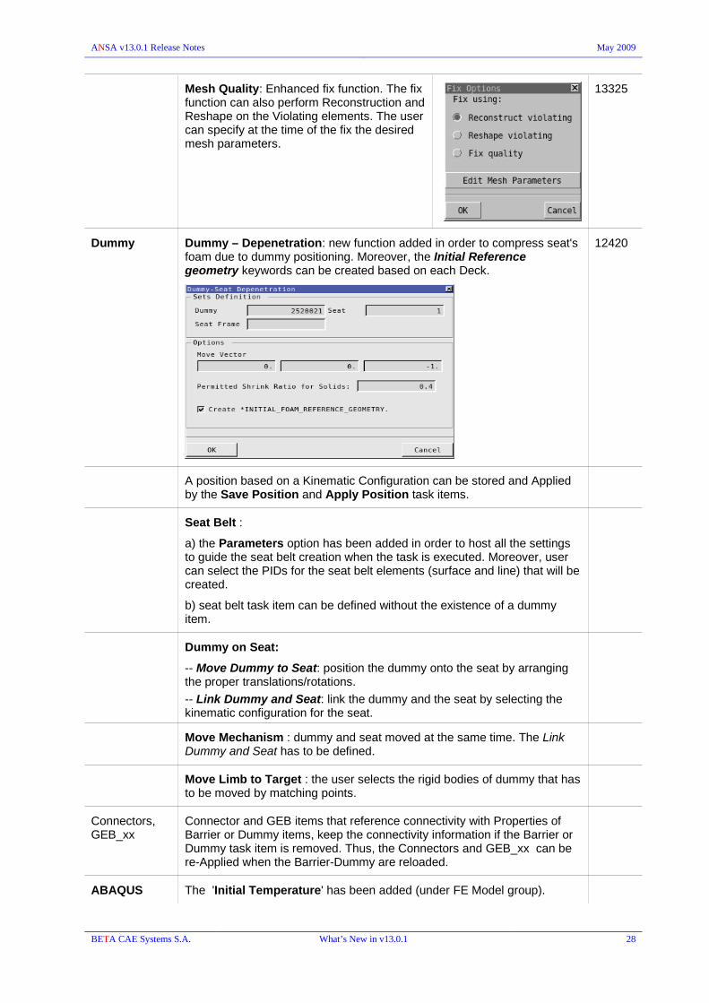
ANSA v13.0.1 Release Notes May 2009
Mesh Quality: Enhanced fix function. The fix function can also perform Reconstruction and Reshape on the Violating elements. The user can specify at the time of the fix the desired mesh parameters.
13325
Dummy Dummy – Depenetration: new function added in order to compress seat's foam due to dummy positioning. Moreover, the Initial Reference geometry keywords can be created based on each Deck.
12420
A position based on a Kinematic Configuration can be stored and Applied by the Save Position and Apply Position task items.
Seat Belt :
a) the Parameters option has been added in order to host all the settings to guide the seat belt creation when the task is executed. Moreover, user can select the PIDs for the seat belt elements (surface and line) that will be created.
b) seat belt task item can be defined without the existence of a dummy item.
Dummy on Seat:
-- Move Dummy to Seat: position the dummy onto the seat by arranging the proper translations/rotations.
-- Link Dummy and Seat: link the dummy and the seat by selecting the kinematic configuration for the seat.
Move Mechanism : dummy and seat moved at the same time. The Link Dummy and Seat has to be defined.
Move Limb to Target : the user selects the rigid bodies of dummy that has to be moved by matching points.
Connectors, GEB_xx
Connector and GEB items that reference connectivity with Properties of Barrier or Dummy items, keep the connectivity information if the Barrier or Dummy task item is removed. Thus, the Connectors and GEB_xx can be re-Applied when the Barrier-Dummy are reloaded.
ABAQUS The 'Initial Temperature' has been added (under FE Model group).
BETA CAE Systems S.A. What’s New in v13.0.1 28

ANSA v13.0.1 Release Notes May 2009
Data Management
Ansa DM toolbar button:
INCLUDE files
Data Management (ANSA DM) is able to handle Include Files (input deck files) as it does for ANSA Parts (ansa databases).
Include Files can have Version, Study Version, Representation thus they can be handled by the ANSA DM functions (Check DM Updates, Reload, Save Representation, Change Representation) through the Includes Manager.
File>Read model definition & ANSA.defaults
Add the variable :
part_id_convert = y
in ANSA.defaults under "Assembler Parameters" section to control whether to strip leading zeros from PART Module Ids and move trailing characters into PART Version when reading a product tree (e.g. VPM tree).
Compare DMs
Choose two different DMs and compare them in several categories (Parts, Boundary Conditions etc).
It is also available to copy or synchronize the contents between the two DMs.
BETA CAE Systems S.A. What’s New in v13.0.1 29

ANSA v13.0.1 Release Notes May 2009
Additionally, advanced filters can be used for the compared items. The User and Last Edit information is also listed.
Check DM Updates:
New options added:
- search for newer study version, based on the current version.
- search for common representation based on the newer version if one has been actually found. Common representations will only be reported, there will be no option to import them in the database.
8095 10939
BETA CAE Systems S.A. What’s New in v13.0.1 30

ANSA v13.0.1 Release Notes May 2009
Compare Versions
– Allow multiple selection: New option that allows switching between single and multiple selection of items in the results lists:
single selection, clicking on items is equivalent to choosing to keep the respective items.multiple selection only changes the status of selected items through the right mouse click options.
- Property thickness field is visible in compare lists even if there is no difference in the thickness value of the compared parts/files.
- New option to save the comparison Report as html or text(csv) file.
- Explode View/Reset can be applied from both lists.
- 'Show Differences Only' button has been removed from the Compare Versions window. Instead a 'Differences Only' option has been added in the Advanced Filtering tool.
In case of transformation matrices differences the user can select which matrix will be kept. Upon confirmation all selected changes are performed, 3 groups are created:
The first contains links of the new incoming parts/groups.The second contains links of parts/groups whose transformation matrix was affected.The third contains links of parts/groups whose version/st version/representation has been changed.
Save Representation : the whole procedure can be discarded, without saving in DM, by pressing Cancel on any of the pop up windows. Moreover, the new dialog boxes enable better communication.
An appropriate Report is given in the Ansa Info window (text) after Change representation, Sync representation or Save representation application.
Save Representation / Change Representation : multiple parts/groups can be selected. 7399
BETA CAE Systems S.A. What’s New in v13.0.1 31

ANSA v13.0.1 Release Notes May 2009
CAD Data Translators
CATIA translation: Important improvements / changes have been done regarding
• The recursively defined Catia V4 *.model files are now translated as single parts: the information of the respective parts and instances is taken. The part is named like the filename (without the path).
• The PIDs are created per BODY but if the BODY names are the same (for different bodies) the same PID is used. This is to avoid creating multiple different PID's for multi instanced .model files for each body instance.
• Significant improvements in “Color to PID” and “Layer to PID” options.
7340
NX translation : each part's attributes is given in the respective ANSA Part comments. The format is :
<Attribute title> : <Attribute value>
The attributes are written in lines (separated by '\n' in the comment)
Names of Curves and Points and the attributes of Curves and points are read in and given to the “Comment” fields of the respective entity card.
Moreover, the attributes of BODY are given in the “Comment” field of the respective Property card.
BETA CAE Systems S.A. What’s New in v13.0.1 32

ANSA v13.0.1 Release Notes May 2009
ANSA – TOSCA environment
A special ANSA environment dedicated to TOSCA Structure can be launched with the option
-gui TOSCA
this is an environment with limited functionality and requires a special license.
BETA CAE Systems S.A. What’s New in v13.0.1 33

ANSA v13.0.1 Release Notes May 2009
Connections & Assembly
Connection Manager
The REALIZE buttons that launches the Connection Manager is now placed in the W.SPOTs Group of buttons in the General buttons menu (bottom menu).
Connections List > Right click menu
Editing : the edit mode is now enabled for a single connection with double click in a field or with Edit option from the right click menu for massive modification of selected connections.
Show Only : keeps visible in the graphic area only the selected connections. Mind that any other already listed connections appear in green in the graphic area although they are are not visible.
Show Parts: makes visible the referenced components that are connected by the selected connections.
Show Parts Only: makes visible only the referenced components that are connected by the selected connections. Any other items are not shown.
Connectivity to Props || Connectivity to Parts : change the referenced connectivity information from Module-ID (Parts) to PID (Props) and vice versa while preserving the realized FE-Representations. It takes also into account the referenced includes and switch the IN-id to PID or Module-id respectively.
Auto detection of connectivity information:
- the settings of the window are now saved in the ANSA.xml for future use.
- “Clear Connectivity”: activate this check box in order to remove all connectivity information and update it with the detected by the function.
9163
Parts/Properties/Includes list
- left click on a component in the list does not affect the visibility of this component.- when a component is selected the connections are not selected in the Connections list.
- Right click menu
Remove from Connections : all selected items are removed from the connectivity information from all selected connections.Select Connections || Deselect Connections : select or deselect the listed connections that are related to the selected components.Show || Hide || Show Only : control the visibility of the selected component affecting also the referenced connections if only the “Apply to Connections” check box is enabled.Select All || Select None : select or deselect all listed components.
Read spots VIP2 : the connection's PID and material's data are interpreted as Comment. This is controlled by the variable vip2_info_to_comments = y which has been added to ANSA.defaults.
7067
BETA CAE Systems S.A. What’s New in v13.0.1 34
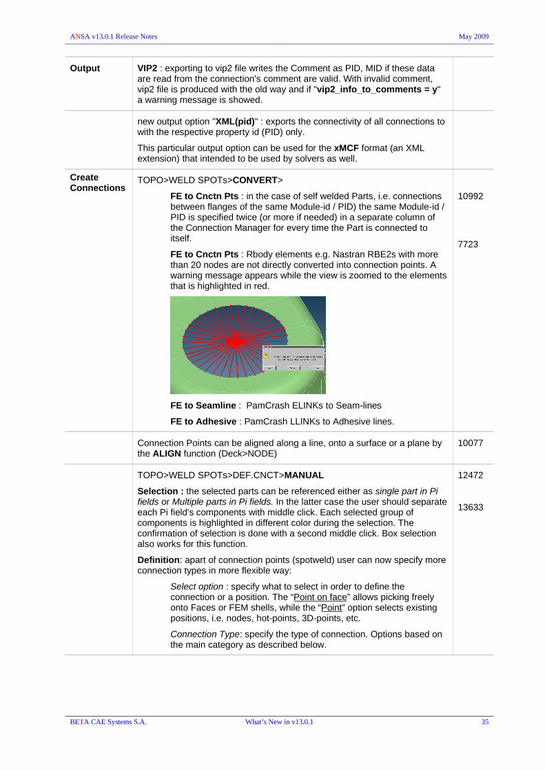
ANSA v13.0.1 Release Notes May 2009
Output VIP2 : exporting to vip2 file writes the Comment as PID, MID if these data are read from the connection's comment are valid. With invalid comment, vip2 file is produced with the old way and if "vip2_info_to_comments = y" a warning message is showed.
new output option "XML(pid)" : exports the connectivity of all connections to with the respective property id (PID) only.
This particular output option can be used for the xMCF format (an XML extension) that intended to be used by solvers as well.
Create Connections
TOPO>WELD SPOTs>CONVERT>
FE to Cnctn Pts : in the case of self welded Parts, i.e. connections between flanges of the same Module-id / PID) the same Module-id / PID is specified twice (or more if needed) in a separate column of the Connection Manager for every time the Part is connected to itself.
FE to Cnctn Pts : Rbody elements e.g. Nastran RBE2s with more than 20 nodes are not directly converted into connection points. A warning message appears while the view is zoomed to the elements that is highlighted in red.
FE to Seamline : PamCrash ELINKs to Seam-lines
FE to Adhesive : PamCrash LLINKs to Adhesive lines.
10992
7723
Connection Points can be aligned along a line, onto a surface or a plane by the ALIGN function (Deck>NODE)
10077
TOPO>WELD SPOTs>DEF.CNCT>MANUAL
Selection : the selected parts can be referenced either as single part in Pi fields or Multiple parts in Pi fields. In the latter case the user should separate each Pi field's components with middle click. Each selected group of components is highlighted in different color during the selection. The confirmation of selection is done with a second middle click. Box selection also works for this function.
Definition: apart of connection points (spotweld) user can now specify more connection types in more flexible way:
Select option : specify what to select in order to define the connection or a position. The “Point on face” allows picking freely onto Faces or FEM shells, while the “Point” option selects existing positions, i.e. nodes, hot-points, 3D-points, etc.
Connection Type: specify the type of connection. Options based on the main category as described below.
12472
13633
BETA CAE Systems S.A. What’s New in v13.0.1 35

ANSA v13.0.1 Release Notes May 2009
Single connection point
at the picked positions the Point Connection Type that is activated will be defined.
Multiple connection points
Point connections are defined but along a described line; either polyline (straight segments) or curve.
The connection points are created along the line based on the 'spacing' and 'margin' parameters.
Connection curve
a connection curve can be directly defined based on a line (polyline or curve) that is created according to the selected positions. Additionally to the other categories a Macro Area's Perimeter can be also selected.
BETA CAE Systems S.A. What’s New in v13.0.1 36

ANSA v13.0.1 Release Notes May 2009
TOPO>WELD SPOTs>DEF.CNCT> HOLES : new function that creates Bolt connections at detected holes either on Geometry or on FEM-mesh.
13471
CHECK CONNECTIONS : new function to check Total Thickness
the sum of the thickness of the connected part is compared to the given value. Connection fails the check if the total thickness of the parts is bigger than the threshold value.
11630
CONNECTIONS > Check intersecting parts
the "SHOW ONLY" button from the Checks list isolates also the relative flanges of the problematic connection. In case of FEM-mesh, 1 zone of neighbors is added.
10971
CONNECTIONS : Fix option besides the renaming of the selected connections, opens the connection manager with the specific connections already loaded.
Scripting CheckConnections( matrix InputConnectionsArray, matrix InputCheckDataArray, matrix OutputCheckReportArray );
12597
BETA CAE Systems S.A. What’s New in v13.0.1 37

ANSA v13.0.1 Release Notes May 2009
FE- Representations
Hemming FOLDING
The FOLDING FE-representation is used to fold a shell element flange on top of another, creating a hem. The hem, consists of an RBE3-HEXA-RBE3 element combination between the bottom and the top flange.
Note that the order with which connectivity strings Pi are specified is significant for the successful realization of the hemming. The last of the connectivity strings must be the component around which the hem flange will be folded and the first must be the component that will be folded as shown in the example below.
Variable folding angle in the same connection can be achieved if the connection is defined on more than 1 curves and the name of a curve includes "folding angle = XXXXX". If such a name is found , the XXXXX value will override the connection manager's value.
All 'folded' nodes (that belong to Macro Area perimeters) return to their original position after Erase-Fe.
BETA CAE Systems S.A. What’s New in v13.0.1 38

ANSA v13.0.1 Release Notes May 2009
Seam Lines
New representations related to durability and fatigue analysis: Heat affected zones can be created assigned a different Property. Zones width and projection's method are controlled in Connection Manager.
Y-JOINT-SHELL
OVERLAP-SHELL
CRIMP-WELD-SHELL
LASER-WELD-SHELL
EDGE-WELD-SHELL
To define the direction of the weld (in the seamweld types that support direction, i.e. Y-JOINT-SHELL, CRIMP-WELD-SHELL), the user can specify a vector by right-clicking on the connection entry in Connection Manager and selecting the option Set Weld Position. The weld position vector is defined by picking two points: The tail should lie on the Connection Line (left click on the seam-line and press middle click to confirm) and the tip should be a node of the model (left click on a node and hit the OK button). The weld position is read in by the xml connection file and is stored in the exported deck file as ANSA Comments.
If the user does not check the zone PID fields, then no heat zone props are created.
The ERASE FE removes any shells generated and the shells of the heat zones are assigned their original PID.
"Base sheet" for seamweld connections:
- "Base Sheet = P1 || P2 :specify the base sheet, without having to swap P1 and P2
- if you set "Base Sheet = Auto", then the parts P1 & P2 are scanned, and the thickest is assumed to be the base-sheet.
Mind that if you try to weld the seams the wrong way round, you will get NO F.E. Representation message.
Moreover, the "BaseSheet" is an attribute that is stored (and required) by the xMCF format.
BETA CAE Systems S.A. What’s New in v13.0.1 39

ANSA v13.0.1 Release Notes May 2009
The realization of the Y-JOINT-SHELL is illustrated in the following images. The heat zones in different properties and the way the weld shells can be created are shown.
All the above can be specified in the Connection Manager. Similarly (with less options in most of them) are realized the rest of these new seam weld types.
The seam weld settings, including the weld position, are read in by the xMCF file in xml format. Mind also that Connection Manager can output this new xml format : XML (pid).
BETA CAE Systems S.A. What’s New in v13.0.1 40

ANSA v13.0.1 Release Notes May 2009
Additionally 5 new representations for Seam Lines, dedicated to FEMFAT solver, are also available :
Y-JOINT-FEMFAT
OVERLAP-FEMFAT
LASER-WELD-FEMFAT
CRIMP-WELD-FEMFAT
EDGE-WELD-FEMFAT.
"Weld type" pull down selection specifies the materials that will be assigned to the heat zones, according to FEMFAT modeling guidelines.
coordinate systems are assigned to the welding nodes:
C100 : Welding seam.
C102: End of welding seam not welded around.
For the Y-JOINT-FEMFAT : no "weld shells" , only heat zones are created.
All the FEMFAT-seamwelds create heat zones that are surrounding the welding cut ( end of welding seam is welded around ).
SEAMLINES (Y-JOINT-SHELL, OVERLAP-SHELL, LASER-WELD-SHELL, CRIMP-WELD-SHELL, EDGE-WELD-SHELL )
Realization of HeatZones With the option 'Weld Around' enabled.
BETA CAE Systems S.A. What’s New in v13.0.1 41

ANSA v13.0.1 Release Notes May 2009
Spot Weld Lines
The spacing value S, for the distribution of the spot welds along the spot line, can either be a positive or negative real number.
A positive spacing value "s" with a margin value "m" implies that upon realization, priority will be given to the preservation of the margin value "m". Thus, the resulting spacing value may vary between "s" and "2s".
A negative spacing value "-s" with a margin value "m" implies that upon realization, priority will be given to the preservation of the spacing value "s". Thus, the resulting spacing value will be as specified, while the actual margin value may vary. In this case, during the output of connection information in xml or vip2 format, a positive spacing value will be exported.
Contact Realizations
DYNA SPOT WELD [Spot Weld Points/Lines]
RADIOSS WELD [Spot Weld Points/Lines]
HEXA CONTACT & COHESIVE CONTACT [Adhesive Lines/Faces]
CONTACT : [Seam Lines]
The field “Contact ID” has been added in the following FE-Representation settings where contact(s) is (are) defined automatically by the realization.
- Contacts that take 'single surface' are not accepted as an input to 'Contact Id' field.
- The new elements (e.g. hexas/beams/cohesives/springs) that are created are placed in the sets referenced by the specified contact, if “Contacts” and “Create Single Contact” check boxes are enabled (where both these check boxes exist; or where only the “Single Contact” check box exists).
- if "Create Single Contact" is disabled (or where there is no this check box), then the given contact is used as a TEMPLATE. Connection Manager will look for a contact that matches the template (i.e. named 'SPOTWELD CONTACT ...', whose master set contains the shell properties needed AND for which the values of fields in the edit-cards all match) and will update its sets. If no matching contact can be found, one will be created by copying the template.
- The 'given' contact must exist and it must support both master & slave sets.
- Merging of contacts does not take place when Contact Id is given.
Point-to-Point Connections:
In case of FE-Repr. elements that are connected to the mesh the projections, and therefore mesh reconstruction, is not performed if a node already exists at the projection position.
The properties, materials, rupture models and coordinate systems, that are automatically created by the connection manager, are erased when the Representation of the connection is changed or the connection is deleted, unless they are referenced elsewhere in the database.
10857
RBE3 pinflags : the representation that contains RBE3 will have as default the following settings:
'Use Separate REFC pinflags' = ON'REFC pinflags' = 123456 , 'RBE3 pinflags' = 123
ERASE FE : Hot-Points on the mesh nodes (Macro Area) where the connection elements were attached are now removed after the FE-Repr. deletion
BETA CAE Systems S.A. What’s New in v13.0.1 42

ANSA v13.0.1 Release Notes May 2009
SpotWeld Point/Line
PAM-PLINK
'Connect To Mesh' option is removed.
'Do Not Move' and 'Dist From Perimeter' options have been added.
The value used in the SPOTRA is compared to the available distance taking into account the new options status.
The 'Dist From Perimeter', works even if SPOTRA = 0mm.
The 'Dist From Perimeter', is useful for cases where it makes no sense to have the spotwelds too close (or outside) the bounds of a flange.
When an existing property is given in the IPART field the values specified in 'Search' , NGESP, SPOTRA and 'Create rupture model' are checked if they match with the existing Plink Property and the used Link Material. The PLINKs are realized but the existing PLINK Property is not changed. The input values are ignored and respective messages appear in the Ansa Info window.
9890
9986
9086
SpotWeld Point/Line
TIE CONN3D for abaqus.
It creates a TIE contact between the nodes and shell properties of the connection's connectivity. CONN3D is always directed from P1 to P2.
There is an option not to create the CONN3D if there is no physical gap between the flanges.
14307
SpotWeld Point/Line
ABAQUS FASTENER : In order to directly reference the Connector Section within the Fastener's card, keep the 'Use connector' check box inactive and specify the CONNECTOR PID. This will create a Connector Section whose ID is referenced in the Fastener's card [CONN.SECTION].
10433
Seam Lines RBE2 , RBE2-CBEAM
"Force Node To Node" : When activated ( default = off ) it will attempt to force 1 to 1 node connections between connection parts. It works only when seamline "snaps" a feature line in both assembly parts ( in the other cases "node to node" was already achieved by projections ). Also , the feature line must be single and continuous on each part ( otherwise seamweld creation will continue as if option was off ). In that case , the 2 perimeters and nearby shells are reconstructed to achieve the desired result, as possible.
4915
Seam Lines CONTACT
Width [W] column is taken into account when adding the flange's nodes to the contact. Nodes within distance 'W' from the edge of the seamweld will be added to the contact.
12551
Adhesive lines
Seam lines
RBE3-HEXA-RBE3, HEXA-CONTACT, RBE3-COHESIVE-RBE3
COHESIVE-CONTACT
Step Length : can be defined as a factor of the Width value [W].
7012
SpotWeld Point/Line
CWELD
- The criterion for the angle between the connected flanges has to be fulfilled. User can specify the angle value threshold.
- GS node is defined for ELPAT type.
- "Distance From Perimeter" : element won't be realized if a value is given and the projection of the connection lies within this distance from the perimeter.
9998
11227
BETA CAE Systems S.A. What’s New in v13.0.1 43

ANSA v13.0.1 Release Notes May 2009
Gum Drops CWELD: mass element is defined on the GS node.
Every GS node of a cweld has a mass and if there are no GS nodes, the mass is applied to the connected cweld nodes which belong also to the mesh ( type = ALIGN). The mass input in the "m" field, is divided according to the number of GS nodes or cweld nodes.
9562
Adhesive lines
SpotWeld Point/Line
RBE3-CELAS1-RBE3
'Create Coords' option has been added
7600
SpotWeld Point/Line
SPIDER2
- “Dist From Perim” option is added. It is measured from the last zone ring of the spider to the perimeter. If no zones exist then it is the distance of hole's free edge to the perimeter.
- “Do Not Move”: option has been improved and in conjunction with “Dist From Perim” safeguard the result of the FE-Representation. Thus, no holes are drilled on bounds.
Feature Lines are detected based on the Shell Parameters.
3395
4782
5901
SpotWeld Points/Line
DYNA SPOT WELD: Option not to create the contact at all
13858
DYNA SPOT WELD: SECTION_BEAM with ELFORM=1 or ELFORM=2 can be selected (these cannot have MAT 100 material) for the PBEAM_ID field.
13851
SPIDER
Create Hexas: this new check box, which can be enabled only if the “Create RBE2” is disabled, provides the PSOLID ID field for the Property ID of the hexa elements which are created. The Hexas are directly connected to the perimeter and inner nodes of the “Center Circles”.
BETA CAE Systems S.A. What’s New in v13.0.1 44

ANSA v13.0.1 Release Notes May 2009
Bolts Body
- the Length can be specified as an absolute value
- Minimum Element Length can be specified
13750
13477
Bolts
SpotWeld
Num of points around hole:
if left blank, or if the node number specified is less than 4, the node number will be calculated automatically, based on the average element length of the neighbor elements. If the average element length dictates less than 4 nodes, 4 will be used.
8055
13786
MESH > WELD SPOTs > ADHESIVE
The option to Search in Visible has been added.
6801
CONNECTORs
Search methods PassThrough option has been added.
ResultsFromSet option has been removed; it can be achieved with Connectivity = SET and Search Method = PassThrough
BETA CAE Systems S.A. What’s New in v13.0.1 45

ANSA v13.0.1 Release Notes May 2009
BATCH Mesh Manager
Main management window
New interface that enables the creation [Add] of Meshing Scenarios and Meshing Sessions as well as Volumes and Layers scenarios.
Refinement Boxes with special meshing parameters for local mesh size treatment can be set up within Meshing Sessions.
New interface for the Scenarios/Sessions contents selection with enhanced filtering options. Selection of Properties to be meshed is also enabled.
FE mesh (no geometry related) can be treated.
BETA CAE Systems S.A. What’s New in v13.0.1 46
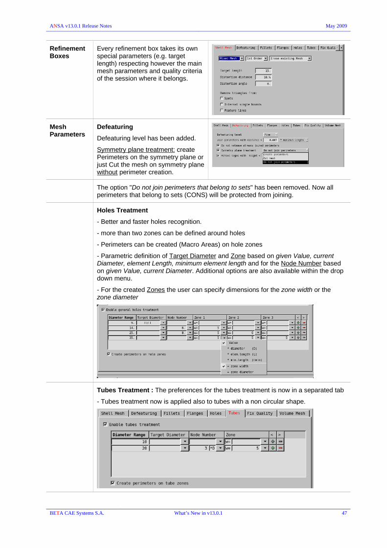
ANSA v13.0.1 Release Notes May 2009
Refinement Boxes
Every refinement box takes its own special parameters (e.g. target length) respecting however the main mesh parameters and quality criteria of the session where it belongs.
Mesh Parameters
Defeaturing
Defeaturing level has been added.
S ymmetry plane treatment: create Perimeters on the symmetry plane or just Cut the mesh on symmetry plane without perimeter creation.
The option "Do not join perimeters that belong to sets" has been removed. Now all perimeters that belong to sets (CONS) will be protected from joining.
Holes Treatment
- Better and faster holes recognition.
- more than two zones can be defined around holes
- Perimeters can be created (Macro Areas) on hole zones
- Parametric definition of Target Diameter and Zone based on given Value, current Diameter, element Length, minimum element length and for the Node Number based on given Value, current Diameter. Additional options are also available within the drop down menu.
- For the created Zones the user can specify dimensions for the zone width or the zone diameter
Tubes Treatment : The preferences for the tubes treatment is now in a separated tab
- Tubes treatment now is applied also to tubes with a non circular shape.
BETA CAE Systems S.A. What’s New in v13.0.1 47

ANSA v13.0.1 Release Notes May 2009
Fix Quality
- Parametrical specification of maximum allowed movement based on target and/or minimum length size.
Layers Scenario
Layers session parameters
The layer scenario and layer session parameters are now specified within its own window.
Volume Scenario
Volume session parameters
The volume mesh mode is specified between:
Tetras structural algorithm , Tetras CFD algorithm or Hexa Interior.
The Size Boxes affect the volume mesh generation defined by Tetras CFD algorithm or Hexa Interior only if they are visible during the meshing.
BETA CAE Systems S.A. What’s New in v13.0.1 48

ANSA v13.0.1 Release Notes May 2009
Session Save Session (right click menu)
The option to save Only the Parts that failed (do not have OK status) has been added. This option allows further handling of mesh improvement.
A Single ansa file can be saved consisting of all parts of the session or each Part can be saved separately.
Import Meshing Files (right click menu)
Use this new option in order to update parts that had been “given” for further mesh improvement after the Batch Mesh.
Once a Batch Mesh session has been completed particular Parts that had failed the desired mesh quality could be saved in a separate ansa file. These files could belong in different sub-assemblies (hierarchy) and they could have multi-instantiated parts as well. When they have been improved and the ansa file is saved, there is a need to Update these parts inside the initial model in the proper position in the hierarchy structure. The “Import Meshing files” finds the respective parts in the initial file (i.e. same Module ID, same Name, same Representation) and automatically updates them with the “incoming” (mesh corrected) parts of the picked ansa file (that is selected via the File Manager). Moreover, it performs Synchronization of Multi-instantiated parts.
The function provides capabilities of the Data Management even though there is no DM_ROOT established.
Scripting new function RunAllMeshingScenarios that runs all active scenarios of DB.
BETA CAE Systems S.A. What’s New in v13.0.1 49

ANSA v13.0.1 Release Notes May 2009
PART Manager
PART manager is activated by the Windows>Parts. A respective button is placed on the top toolbar (by default).
Main window
Replace New dialog boxes with additional options for the part replacement operation.
Ability to save the Replace Report in a html or txt file. 8207
Delete When a Link part is picked the option “Follow Links” becomes available in the dialog box and if it is disabled only the picked Part will be deleted. If the check box is enabled the source Part is deleted as well.
Right mouse button menu
ANSA defaults
New option in ANSA.defaults called 'ShowOnlyHideRelated'.
It can be assigned 2 values: 'Connections' and 'ConnectionsConnectors'.
Controls whether related connectors will be shown through Show Only along with related connections. Set the value to 'ConnectionsConnectors' so that related connectors will be made visible.
10642
The “study version” information is saved within ANSA_Comments for the ANSA Parts.
14209
Save Save Part function now offers separate options for connections and connectors. User can select to save only connections or connectors( internal/affected) or both.
8642
BETA CAE Systems S.A. What’s New in v13.0.1 50

ANSA v13.0.1 Release Notes May 2009
Compare from file
– Allow multiple selection: New option in that allows switching between single and multiple selection of items in the results lists:
single selection, clicking on items is equivalent to choosing to keep the respective items.
multiple selection only changes the status of selected items through the right mouse click options.
- Property thickness field is visible in compare lists even if there is no difference in the thickness value of the compared parts/files.
- New option to save the comparison Report as html or text(csv) file.
- Explode View/Reset can be applied from both lists.
- 'Show Differences Only' button has been removed from the Compare Versions window. Instead a 'Differences Only' option has been added in the Advanced Filtering tool.
Identification and handling of Groups that have entities referenced directly to them
Group icons will contain a (!) mark in case they have entities of their own(which do not) belong to any child-parts. When right clicking on them you get another option regarding Show/Hide/Show only of this groups. You can either handle all selected entities (groups and the included parts) or just the entities that are referenced directly by the selected groups.
9652
BETA CAE Systems S.A. What’s New in v13.0.1 51

ANSA v13.0.1 Release Notes May 2009
TOPO
HOT-POINTs INTERS. : The Extend option has been added in all cases of intersection. 613
CONS PASTE :
- it is now allowed to paste non-frozen CONS to frozen CONS. In case of different node distribution the nodes of the frozen cons are preserved.
- chain of CONS (e.g. two opposite strips) can be selected to be pasted
- in case of non-uniform selected CONS the Alt. option can be activated for an alternative paste solution.
1178
2440
RELEASE: selection of a chain CONS is enabled. The Corner angle selection tool is available. The hot points that take part are also released, but only the necessary ones.
FACEs MIDDLE>MULTI
This new function creates the middle faces between two sets of faces, selected either manually, assisted by selection tools, or by automatic identification. The new faces will lie on a new surface that is created between the surfaces of the two selected sets of faces. The shape of the resulting middle faces is a combination of the perimeter shapes of the two selected sets of faces.
BETA CAE Systems S.A. What’s New in v13.0.1 52
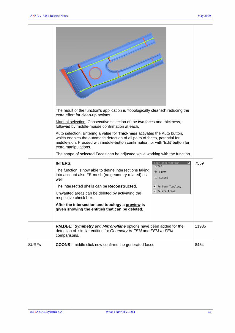
ANSA v13.0.1 Release Notes May 2009
The result of the function's application is “topologically cleaned” reducing the extra effort for clean-up actions.
Manual selection: Consecutive selection of the two faces and thickness, followed by middle-mouse confirmation at each.
Auto selection: Entering a value for Thickness activates the Auto button, which enables the automatic detection of all pairs of faces, potential for middle-skin. Proceed with middle-button confirmation, or with 'Edit' button for extra manipulations.
The shape of selected Faces can be adjusted while working with the function.
INTERS.
The function is now able to define intersections taking into account also FE-mesh (no geometry related) as well.
The intersected shells can be Reconstructed.
Unwanted areas can be deleted by activating the respective check box.
After the intersection and topology a preview is given showing the entities that can be deleted.
7559
RM.DBL: Symmetry and Mirror-Plane options have been added for the detection of similar entities for Geometry-to-FEM and FEM-to-FEM comparisons.
11935
SURFs COONS : middle click now confirms the generated faces 8454
BETA CAE Systems S.A. What’s New in v13.0.1 53

ANSA v13.0.1 Release Notes May 2009
CURVEs NEW>PICK: a dynamic preview is available during selection.
'Tangent at Start' : pick a curve where it's tangent will be the start of the new curve. The direction of the new curve can be changed by pressing the 'Reverse' button.
'Tangent at End' : pick a curve where it's tangent will be the end of the new curve. If needed, pick also any points from which the new curve will pass through them and the option 'Detach curves' will become available. By enabling it, the start and end curves become detached from the rest of the new curve.
If the 'Merge curves' is enabled, can merge the chain of curves that were selected.
NEW>BOX : creates curve based on positions collected by box selection.
Exact : generates curve that passes through the given points (for input data a line (or lines) of points).
Through cloud : generates a mid-curve (for input data a line (or lines) of points with noise data of "cloud width" thickness).
Single : generates one curve.
Multi : generates multiple curves with minimum distance from each other "distance".
10557
CONNECT>SINGLE:
If the “Merge curves” is enabled, can merge the chain of curves that were selected.
11308
EXTEND : the button has been removed. The extend curve can be achieved through the NEW>PICK (tangent only at start) or with the CONNECT>SINGLE
NORMAL : a 3D curve can be created as a normal line onto a shell element. With the right click snap to an existing position.
8687
POINTs NEW>IN_LINE : create 3D points along a straight line formed by two picked positions (any type of points) counting also the picked positions.
7151
ONCOG : Added automatic-hole selection has been added for EDGES
BETA CAE Systems S.A. What’s New in v13.0.1 54
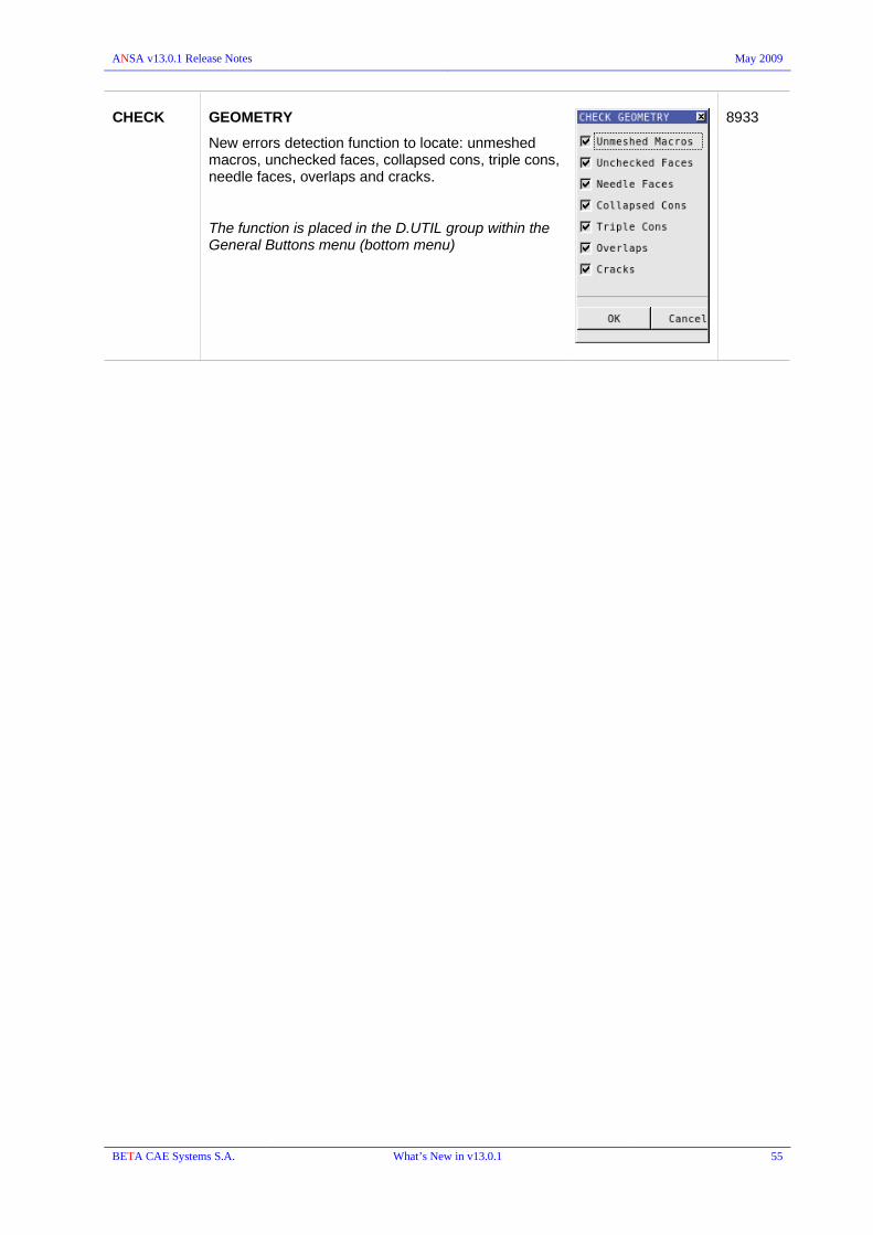
ANSA v13.0.1 Release Notes May 2009
CHECK GEOMETRY
New errors detection function to locate: unmeshed macros, unchecked faces, collapsed cons, triple cons, needle faces, overlaps and cracks.
The function is placed in the D.UTIL group within the General Buttons menu (bottom menu)
8933
BETA CAE Systems S.A. What’s New in v13.0.1 55

ANSA v13.0.1 Release Notes May 2009
MESH
The buttons of the MESH Module has been re-arranged.
A Buttons Group MESH GEN. hosts now functions related to Mesh Generation, the SHELL MESH hosts the Mesh Parameters and functions related to mesh manipulation and improvement.
When a new Macro Area Perimeter is generated, e.g. by MACROs>CUT>Cut the length of the new perimeter is defined based on the neighboring segments or the macro area's other perimeters.
13286
If the Target Element Length that is given in the Reconstruct/Reshape Parameters (SHELL MESH>PARAM.) is smaller than the Minimum Element Length (F11>Quality criteria) a warning message appears at the application of RECONS. or RESHAPE functions.
PERIMETERS INFO: Multiple selection is enabled.
NUMBER: multiple selection of perimeters is now possible. The given number will be assigned to all selected perimeters.
7731
9777
MACROs The CREATE function ( and the respective session command ) has been removed.
GRIDs MV.FREE:
Num. input : enables the typing in the X,Y,Z fields. The input values correspond to the new coordinates of the node.
Keep view mode : by activating this check box the affected elements are drawn according to the current drawing mode(s).
Move Links : enables the movement on the node of the corresponding 'link' mesh (e.g. mesh on the Symmetric link macro area).
ORIGIN : returns the node(s) to the initial position.
use the keyboard numeric buttons1-7 to enable/disable the check boxes of the MV FREE window.
Snapping can be achieved by pressing the right mouse button over an existing point.
5782
11051
MESH GEN. BEST
Options : user can specify within the Best Options window:
- the mesh generators that will run
- the order of the mesh generators
- if the best quality mesh or the firstly created mesh result will be kept.
As soon as the BEST function completes its operation reports the number of meshed Macro Areas that were meshed by each of the specified Mesh Generation algorithms.
BETA CAE Systems S.A. What’s New in v13.0.1 56

ANSA v13.0.1 Release Notes May 2009
SHELL MESH
PARAM. : Mesh Parameters window
General
Target element length : can be defined based on the average length or by respecting different local element length.
Freeze > Volume skin : preserves intact the shells comprising the outer skin of a volume definition.
Fem : the FEM perimeter recognition settings are placed in a special tab
These settings are used by the RECONS, SMOOTH and FIX QUAL functions
Defeaturing
This tab hosts the defeaturing settings that are used by the RESHAPE function.
Defeaturing level: draft || middle || fine : controls the level of details (features) that will be kept, i.e. more details (feature line perimeters) are preserved with fine.
Symmetry plane treatment: create Perimeters or just cut the mesh along the symmetry plane.
The option "Do not freeze perimeters that belong to sets" has been removed. Now all perimeters that belong to a set will be protected from joining.
8373
BETA CAE Systems S.A. What’s New in v13.0.1 57

ANSA v13.0.1 Release Notes May 2009
Holes
Use all or any of the criteria for the bolt holes detection
the Target Diameter can be specified by: an absolute Value, as a parameter of the Diameter, the element Length or the minimum element length.
Node Number can be defined by a Value as a parameter of the Diameter or to preserve the initial value based on the element length and distortion.
Zones : more than 2 zones can be specified (max. = 15). The size can be referenced either as a width or as diameter. Both can be given as Value or as parameter of diameter, element length or minimum element length.
RECONS: reconstruct between FEM mesh and MACROS mesh is supported
RECONS – RESHAPE > Violating
auto-selects only the elements that violate the quality criteria with a number of zones around them. The number of zones is determined by the respective field in PARAM>Fix Quality.
RESHAPE : the function can be applied also on FEM-mesh and defeature in the same manner as it does for the macro area perimeters.
FILL: the function, placed in the SHELL MESH buttons group, has the options: Hole || Gap (Free) || Gap (Coons)
The function is now able to handle openings formed between Macro Area and FEM-mesh.
13340
Preview of mesh reconstruction
yellow nodes : connected with non selected FEM elements
white nodes : corner nodes (can be deselected) or more than 2 perimeters junctionorange perimeters : perimeters contained in a SET
magenta perimeters : boundaries between different properties or between macro areas and FEM mesh.
dark green perimeters ... perimeters on CONS
BETA CAE Systems S.A. What’s New in v13.0.1 58

ANSA v13.0.1 Release Notes May 2009
COLLAPSE
Use this new function to “repair” FE-model mesh by means of needle element collapsing. The repair is applied on visible elements. In the parameters window enter the collapse tolerance that will be used and activate, if required, the option to smooth the curvature of the STL surface. The repairing tool will locate and remove collapsing elements while maintaining the important feature lines.
REFINE
New function apply local mesh refinement. A preview of the refinement result is displayed. The refinement takes place by means of edge splitting.
You can apply more refinement steps, adjust the refinement area, select either mixed or quad mesh type, control the transition zone, freeze the free edges. An external transition zone is added at selected shells
The refinement parameters can be set in the respective tab of the Refinement preview window. The mesh style can be also specified: Mixed Mesh, Radial Quad Mesh, Quad Mesh, Smoothed Quad Mesh.
5663
In the Steps tab modify manually the Refinement Area by adding (+) or subtracting (-) zones of elements. Moreover the refinements are performed by means of steps using the forward and backward arrows.
If at once step the mesh style or other options need to be changed, use the Apply button to repeat the refinement using the new settings.
On the other hand, in the Parameters tab specify the refinement settings, including minimum length and maximum refinement steps as well as number of transition zones. Pressing the Apply button the refinement is performed.
BETA CAE Systems S.A. What’s New in v13.0.1 59

ANSA v13.0.1 Release Notes May 2009
Refinement mesh styles
Radial Quad Mesh Quad Mesh
Mixed Mesh Smoothed Quad Mesh
BETA CAE Systems S.A. What’s New in v13.0.1 60

ANSA v13.0.1 Release Notes May 2009
UTIL
All mesh manipulation functions, be means of feature creations, are available through th Utilities Parameters window:
Project Points | Project Edges | Project Perimeters | Open Holes | Created Zones | Plane Cut
The functions can be applied on selected shells based on the “Area Selection” tool.
Click on the label of the function in the Utilities Parameters in order to activate the function's settings.
More than one functions can be executed simultaneously.
The Number of shell zones affected for these functions is controlled by each function's settings.
Projection mode : Normal || Screen || User is available for Project line/point and Open hole.
Projection Tolerance : if the check box is activated the projection is applied if the distance of the picked item is within the input tolerance value.
If the function is applied onto Macro Area there are options to Cut faces on result edges or zones.
The functions manipulate the mesh based on the Mesh Parameters specified by PARAM. function and the Quality criteria defined in F11 window.
2849
9549
6347
11059
6671
Project Points
Move projection to nearest perimeter : in case of projection onto macro area, the projected position is moved to the closest perimeter.
Move to projected point (0-1) : define parametrically the new position of the node that is produced by the projection. Zero (0) position is the projection's origin (picked position) and one (1) is the projection onto the mesh (red point).
Paste projected and result grids : the picked nodes pasted to the projected positions.
The new nodes generated by the projection can be added in a Set.
When projection is done onto a Macro Area the projected nodes can be Marked as WeldSpots.
5327
1771
BETA CAE Systems S.A. What’s New in v13.0.1 61

ANSA v13.0.1 Release Notes May 2009
Open Holes
Holes per projection enables the opening of holes on the same selected area if needed due to its shape.
The elements of the zones can be added to a Set
2413
Project Edges
Use this function to select edges of shell/solid elements as projection source.
Zones around the projection result can be defined.
The elements can be disconnected (released) along the resulted line.
11713
BETA CAE Systems S.A. What’s New in v13.0.1 62

ANSA v13.0.1 Release Notes May 2009
Project Perimeters
Use this function to select 3D curves , shell/solid element edges and morphing box edges can be used as projection source.
Define the target length or target edges number of the selected perimeter.
Create Zones
define zones of quadrilateral elements around edges.
Set the number of zones and offsets (zone size), target edge number (length of the elements along the selected edges).
Plane Cut
The plane that cuts the mesh can be defined either by 3 picked positions, by 2 positions as normal to the screen or by an existing working plane.
5837,
11713
SUPPRESS
New function that can be used to Flatten or smoothen beads, embosses and other features. Specify the maximum feature angle of the resulting shells in the "Edge angle limit" field. The smaller the angle limit the smoother the result.
8498
BETA CAE Systems S.A. What’s New in v13.0.1 63

ANSA v13.0.1 Release Notes May 2009
ELEMENTs INFO: information of the selected element is displayed on screen based also on the current drawing view mode:
QGRAPH : the value for the currently criterion (of the QGRAPH mode) is shown on the screen.
HIDDEN : all violating criteria are shown on the screen.
Moreover, only the active criteria will be calculated and printed in the Ansa Info window.
TO-SURF > PER AREA
Create FACEs based on FEM mesh. The Area Selection tool assists the mesh selection. The boundaries of the generated FACEs are automatically defined and can by customized by the user.
SWAP
The function automatically detect cases were swapping would lead to unaccepted mesh and thus is not applied.
Left mouse clicking on the new edge recycles through the acceptable cases.
Right mouse clicking on the common edge of 2 trias joins the trias.
3692
5167
SPLIT
Direct preview of the split elements.
TSHELL (thick shells) can be split as Solid.
SPLITQ
New function to perform diagonal split on quadrilateral elements, to create triangular elements, based on:
Quality of the resulted trias, Orientation of the produced trias, Violation of quality criteria of the selected quads.
With the Violating option the function splits quads only if they violate one of the related criteria: warping, skewness, tapper min /max angle.
A preview of the split result is shown.
BETA CAE Systems S.A. What’s New in v13.0.1 64

ANSA v13.0.1 Release Notes May 2009
TO-SURF > PER ELEMENT
Options to Join CONS that are produced, according to an angle limit between the initial Shells or Facets, and Delete the FEM shells that was selected. After the deletion the neighboring elements are topologically connected to the created FACEs.
7563
EXTRUDE
Create Shell elements by extruding edges based on GLIDE or SWEEP method.
11138
WRAP > Variable Length
Creates finer mesh around locations of high curvature.
Specify different mesh length parameters for each involved property, in order to control element length locally.
PENETRATION > ELEMENT LENGTH
“Check positive orientation only” check box enables the detection of penetration based on the element's orientation. This options replaces the previous “Based on volume".
10565
13734
BETA CAE Systems S.A. What’s New in v13.0.1 65

ANSA v13.0.1 Release Notes May 2009
VOLUMEs VOLUME Entity card for each volume mesh type and the respective parameters.
Note that the MESHV specifies (might change) the Type option
5305
LIST : volume definitions management window
FREEZE / UNFREEZE volume entities
MODIFY : change the surface that define the volume
REMESH: takes into account the Type specified in the Volume Entity card.
REMESH, FREEZE, UNFREEZE
exists both as options within the LIST of Volumes and as buttons in the VOLUME group of buttons.
DETECT : improved detection of volume definition. Several cases are now covered by the available detection options.
9062
9874
PARAM : Tetrahedral meshing parameters
A coordinate system can be chosen to guide the tetra elements creation
MESHV : DELAUNAY volume meshing algorithm is available.
BETA CAE Systems S.A. What’s New in v13.0.1 66

ANSA v13.0.1 Release Notes May 2009
MAP:
- Definition of Map Areas: Master = blue, Slave=green, Round=red (click OK to create the mapped volume mesh).
- redefinition/modification of the Map areas : click on the respective button in the Map window
- Remesh a Map Volume entity (via the Volumes List) is now possible. The definition of the Map areas is stored.
A map volume cannot be created if the selected map-areas specify an already existed volume definition. A warning message is given in this case.
If Linked Faces (parent or child) have been selected to define the Mapped-Volume, the related Link faces are auto-detected and the respective volumes that are comprised by them, can be automatically map-meshed as well without selecting them.
13365
LAYERS
New Layers generation function that provides advanced options.
The projection of layers is automatically operated and the added options allow greater control over the layers generation resulting in higher quality.
Vector separation at sharp edges: Separate the layers growing from edges that exceed a predefined angle.
Excluded areas: not grow layers from an area based on specific criteria.
Allow Squeeze: Squeezing of layers that exceed specific criteria.
Layers from zero thickness walls: A new enhancement that identifies zero thickness walls and grows layers from both sides.
Layer sides auto-connect: The layers tool has automated the procedure of layers sides connection.
Generation of quad-tria interface: New option creating a non conformal quad-tria interface.
Layers growing from selected areas with different settings: The selection of the areas where layers will grow from is controlled by a separate list that allows the user to select different areas based on properties or parts and with different parameters. Selection can be done either by Property or ANSA_Part
BETA CAE Systems S.A. What’s New in v13.0.1 67

ANSA v13.0.1 Release Notes May 2009
Note that layers will always grow on the positive (gray) side, therefore the model must be correctly oriented. Also the layers parameters can be saved in a file (.ansa_lpar) and used on different models several times.
LAYERS>PROJECT_LAYERS has been removed.
COMP.SKIN
This function detects incompatibilities between visible unstructured volume mesh and visible skin shells and is able to locally remesh the volume mesh to fix the problem.
Detection results are given in preview allowing selection/deselection.
Moreover, the check box [Auto remesh tetrahedral volume on skin changes] has been in Windows->Options->Settings->Mesh: enables direct remesh of unstructured volumes on skin modifications made by the Element modifications and not Mesh Generation or Reconstruction.
HEXBLOCK : hexahedral mesh creation based on selected wireframe. Volume definition is created and is able to be edited and remeshed.
3D curves or MORPH Boxes can be selected.
1473
For Curves selection, minimum 4 (maximum 12) sets of curves are required. A given curve-group can be Modified.
For Morph selection there is an option to auto-load the generated hexas into the Morphing box.
BETA CAE Systems S.A. What’s New in v13.0.1 68

ANSA v13.0.1 Release Notes May 2009
A preview or the nodal distribution together with the Volume Hexa Block parameters and a System-definition (S,T,W) is given. The Number of Nodes along each direction and biasing method (No biasing || Linear || Exponential || Bell Curve) can be defined.
IMPROVE
Automatic improvement of volume elements
RECONS : reconstructs selected tetras and pyramids. RECONS option is controlled by the quality criterion value specified in VOLUMEs>PARAM, say NASTRAN aspect=3 or Fluent Skewness=0.8, and not the F11 Quality Criteria window.
SMOOTH : smooths tetras, pyramids, pentas and hexas. It can also affect the volume and surface mesh simultaneously provided that the flag Freeze Volume Skin is off in the SHELL MESH>PARAM [General Tab]
FIX QUAL : fixes hexa warping and for second order elements mid-point deviation and alignment and Jacobian of tetras only. This is achieved by the automatic movement of nodes only by the distance required so as the elements will have acceptable criterion value. Fix Qual is controlled by SHELL MESH>PARAM and F11 Quality Criteria window values.
Scripting :
Function to find a volume by the coordinates of a point :
xyzIsInsideVolume (float, float, float);
functions for tetra mesh volumes by their ID
HexaInteriorbyID (int,int,float)
TetraCFDbyID (int)
TetraFEMbyID (int)
BETA CAE Systems S.A. What’s New in v13.0.1 69
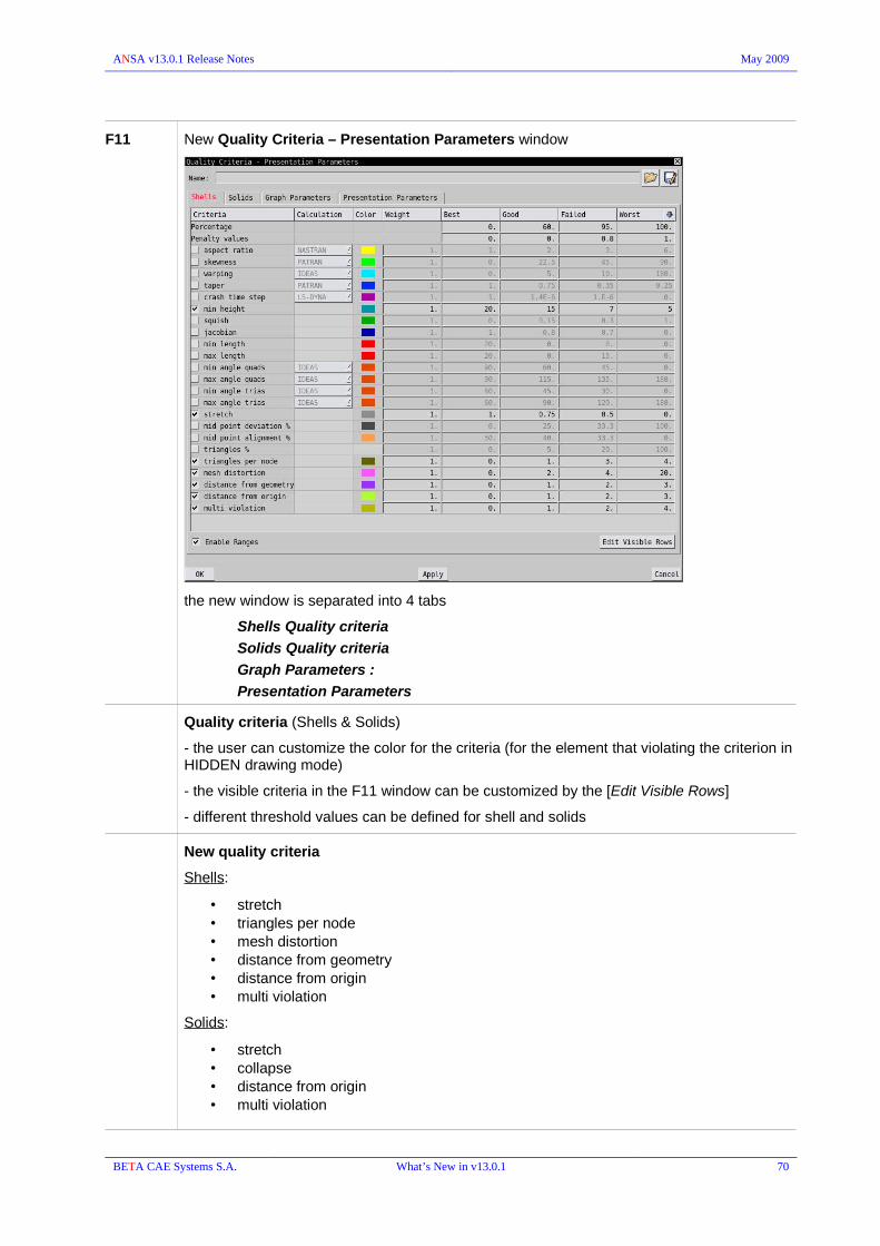
ANSA v13.0.1 Release Notes May 2009
F11 New Quality Criteria – Presentation Parameters window
the new window is separated into 4 tabs
Shells Quality criteria
Solids Quality criteria
Graph Parameters :
Presentation Parameters
Quality criteria (Shells & Solids)
- the user can customize the color for the criteria (for the element that violating the criterion in HIDDEN drawing mode)
- the visible criteria in the F11 window can be customized by the [Edit Visible Rows]
- different threshold values can be defined for shell and solids
New quality criteria
Shells:
• stretch• triangles per node• mesh distortion• distance from geometry• distance from origin• multi violation
Solids:
• stretch• collapse• distance from origin• multi violation
BETA CAE Systems S.A. What’s New in v13.0.1 70
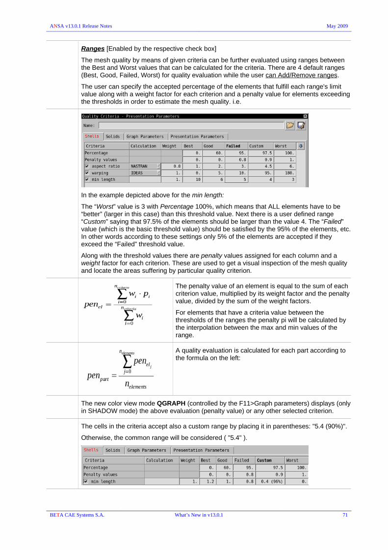
ANSA v13.0.1 Release Notes May 2009
Ranges [Enabled by the respective check box]
The mesh quality by means of given criteria can be further evaluated using ranges between the Best and Worst values that can be calculated for the criteria. There are 4 default ranges (Best, Good, Failed, Worst) for quality evaluation while the user can Add/Remove ranges.
The user can specify the accepted percentage of the elements that fulfill each range's limit value along with a weight factor for each criterion and a penalty value for elements exceeding the thresholds in order to estimate the mesh quality. i.e.
In the example depicted above for the min length:
The “Worst” value is 3 with Percentage 100%, which means that ALL elements have to be “better” (larger in this case) than this threshold value. Next there is a user defined range “Custom” saying that 97.5% of the elements should be larger than the value 4. The “Failed” value (which is the basic threshold value) should be satisfied by the 95% of the elements, etc. In other words according to these settings only 5% of the elements are accepted if they exceed the “Failed” threshold value.
Along with the threshold values there are penalty values assigned for each column and a weight factor for each criterion. These are used to get a visual inspection of the mesh quality and locate the areas suffering by particular quality criterion.
The penalty value of an element is equal to the sum of each criterion value, multiplied by its weight factor and the penalty value, divided by the sum of the weight factors.
For elements that have a criteria value between the thresholds of the ranges the penalty pi will be calculated by the interpolation between the max and min values of the range.
A quality evaluation is calculated for each part according to the formula on the left:
The new color view mode QGRAPH (controlled by the F11>Graph parameters) displays (only in SHADOW mode) the above evaluation (penalty value) or any other selected criterion.
The cells in the criteria accept also a custom range by placing it in parentheses: "5.4 (90%)".
Otherwise, the common range will be considered ( "5.4" ).
BETA CAE Systems S.A. What’s New in v13.0.1 71

ANSA v13.0.1 Release Notes May 2009
QGRAPH color view mode / F11>Graph Parameters
Shell elements can be colored according to their quality, based on a certain criterion.
Once the ranges have been defined, select “criterion” as the option to plot for the “Quality Graph by: “
Choose the Color Bar Limits [Visible || Whole DB || User min-max || Ranges defined min-max]
Choose the Coloring rules in the Color Bar ColorsPalette (add/remove and edit colors if needed), Unique Color , unique color for each range
Switch to SHADOW and QGRAPH modes to display the mesh quality
CHECK BOUNDARY TRIAS
Identify triangles attached to inner or outer boundaries. The Fix option removes them or move them away from the boundaries by locally reconstructing the mesh.
2028
13480
13654
BETA CAE Systems S.A. What’s New in v13.0.1 72

ANSA v13.0.1 Release Notes May 2009
DECKs
New Deck pre-processing Module menus :
- CFD++
- FLUENT
- FLUENT-2D
- OPENFOAM
- STAR ( Star-CD & Star-CCM )
- UH3D
- PERMAS
The respective formats are, therefore, supported by INPUT and OUTPUT.
FEM entities visibility
The DECK PARAMETERS window accessed by the F12 key has been removed.
The visibility of the FEM entities (as well as for all entities) is controlled by the Database Browser. However, if this is not open the F12 key opens it.
Filtering
Modification
The FILT.MOD. function has been removed by the drop menus of the INFO buttons (e.g. ELEMENT>INFO> ).
All filtering and modification capabilities are integrated as list features.
Quick filtering of the list entries can be achieved by typing filtering keywords or regular expressions in the field at the top. As soon as the user starts typing, ANSA suggests alternative filtering possibilities with auto-completion. The alternatives are listed in the drop-down menu and the user can navigate through them with the up/down arrow keys. Pressing ENTER applies the specified filter.
Typing an integer number automatically detected as id filtering while typing alphanumeric characters in the filter field, it is automatically considered as name filtering.
Quick Modify : The attributes of the listed entities that were added as columns in the list can be quickly modified without the need of editing their cards. Quick-modification for an attribute of selected items can be achieved by typing the modification expression in the field that appears with right-click on the column header.
Besides the simple and quick filtering and modification, advanced tools are provided for more complicated applications:
BETA CAE Systems S.A. What’s New in v13.0.1 73

ANSA v13.0.1 Release Notes May 2009
Advanced Filtering Procedures are performed by the Advanced Filter window which is invoked by the Advanced button in any List.
On the Filter Name section, all advanced filters already defined for the entities of this particular list are listed. The user can add a filter by picking the New option of the right-click menu. A defined filter can be renamed, copied or deleted with the respective options.
In the Filter Rules section, the actual filtering rules are defined: The attribute affected by a filter rule is defined in the left field. Typing the attributes name enables the auto-complete feature, which suggests in a pull-down menu all valid options. Additionally, this list contains any attributes that already exist as columns in the list.
Combinations of existing filters can be defined as well.
All the advanced filters that have been defined in an ANSA session or have been invoked through the ANSA.xml customization file can be found in the Filters window, under the Database toolbar button or through the Windows>Database menu option. The Filters window appears by default as a tab in the Database Browser window.
Advanced Modification Procedures can be applied through the Modify window which is invoked by the Modify option of the right-click menu in any List. The entities to be modified are the ones that are selected when the Modify window is invoked.
The attribute affected by a modify rule is defined in the left field. Start typing the attribute's name enables the auto-complete feature, which suggests in a pull-down menu all valid options. Additionally, this list contains any attributes that already exist as columns in the list or have been used for modification before.
The modification pattern is defined in the field on the right. A modification pattern can either be the literal new value the attribute should get, or a Modify Syntax expression. Expressions allow the modification of attributes based on their current values or based on the current values of other attributes within the same card.
! Note that when the Modify window is invoked for a list where a modification had taken place before, the last modification rules applied are displayed.
BETA CAE Systems S.A. What’s New in v13.0.1 74

ANSA v13.0.1 Release Notes May 2009
Additionally to the method through the Filter Rules and Modify Rules windows there is the option to choose the fields to be filtered or modified through the edit card of the listed entities accessed by the “Open Card” button.
The “edit” card is available only for the type but not for the group, i.e for Shell Properties or Beam Properties but Not for All Properties.
The card of the respective (selected) entities opens. Enable the label of the field and type the filtering or modification expression and thus perform the filtering/modification directly in this card, without creating filtering or modification rules by adding fields.
BETA CAE Systems S.A. What’s New in v13.0.1 75

ANSA v13.0.1 Release Notes May 2009
Load Curves
Data Table
Within the Database Browser List the fields of “curve” definitions can be treated (Filtering/Modify) , e.g. :
Pam-Crash>FUNCT : SCALEX, SCALEY, SHIFTX, SHIFTY.
LS-Dyna>DEFINE CURVE : OFFA, OFFO, SFA, SFO
ABAQUS>AMPLITUDEs : SCALEX, SCALEY, SHIFTX, SHIFTY
8137
11399
INCLUDEs The Includes Manager has been moved from the Deck>Auxiliaries Group and is now accessed by the MENUBAR>Windows>Database. Therefore can be active along with other functions.
When selected entities (from a List) are dragged and are about to be dropped into the Includes list, a New Include can be defined directly if the entities are dropped onto the [New Include] box.
BETA CAE Systems S.A. What’s New in v13.0.1 76
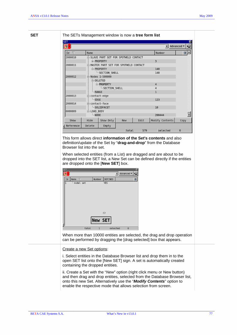
ANSA v13.0.1 Release Notes May 2009
SET The SETs Management window is now a tree form list
This form allows direct information of the Set's contents and also definition/update of the Set by “drag-and-drop” from the Database Browser list into the set.
When selected entities (from a List) are dragged and are about to be dropped into the SET list, a New Set can be defined directly if the entities are dropped onto the [New SET] box.
When more than 10000 entities are selected, the drag and drop operation can be performed by dragging the [drag selected] box that appears.
Create a new Set options:
i. Select entities in the Database Browser list and drop them in to the open SET list onto the [New SET] sign. A set is automatically created containing the dropped entities.
ii. Create a Set with the “New” option (right click menu or New button) and then drag and drop entities, selected from the Database Browser list, onto this new Set. Alternatively use the “Modify Contents” option to enable the respective mode that allows selection from screen.
BETA CAE Systems S.A. What’s New in v13.0.1 77

ANSA v13.0.1 Release Notes May 2009
The “Modify Contents” opens the 'Modyfing SET ...' selection mode window where the type of entity that should be selected is chosen. Along with this a List window opens with the entities of a particular type (the one chosen in the 'Modyfing SET ...' selection mode window).
The entities already contained in the set (if any) are marked in the List whereas the 'In SET' column displays in red the number of the contained items of each type.
Use Ctrl+left_click to deselect or select entities from the List or use left / right mouse button to select/deselect from the screen. Related selection tools appear to facilitate the selection from the screen.
middle click to confirm the set's contents modification.
Double click onto a Type label within a SET to open the Database Browser List with the entities of this type. If the Browser List is already open, the List switches to the proper type (the one picked in the SET).
The Add option [right click menu]
Using this option you can add Edges, Solid element Facets, Ranges or Exclude definition.
BETA CAE Systems S.A. What’s New in v13.0.1 78

ANSA v13.0.1 Release Notes May 2009
The Edges and Facets options enable screen selection. Mind that Edges and SolidFacets can be also added in a Set using drag-and-drop from the Database Browser list.
The Set Range option opens the RANGE card where can be specified the Type [NODE || ELEMENT || PROPERTY] and the START/END Ids.
The Excluded option allows the exclusion of entities which otherwise would be included in the SET. Once you have enabled (Add) an Excluded section within the set (appears as DELETED), you can drag and drop entities into this Excluded section.
Remove option [right click menu]
With right click onto a Set's type of entities (e.g. Property) all the items of this type can be removed from the Set.
Right Click on RANGE > “Convert to Entities“ :
converts the range to its entities. The contained items in a range (currently existing in the model) are placed in the same set (according to the Type they were defined in the Range) ; the Range definition is removed.
11548
A SET is now able to contain SETs, ANSA Parts and ANSA Groups.
Numbering Rules > [ General || Per Type || From File ]
can be defined for Sets.
Line Elements Line elements such as Beams have the field "Element Length" in their entity card. This new field is not editable.
General COMMENT
ANSA General Comments length can be defined in ANSA.defaults through option :
GeneralComments.MaxLength
Valid values are: "undefined" or the number of characters.
13338
BETA CAE Systems S.A. What’s New in v13.0.1 79

ANSA v13.0.1 Release Notes May 2009
PROPERTY LIST
The Property List is now open by the MENUBAR>Windows>Property (appears also as a toolbar button by default) and the Database Browser as well.
The PROPs> INFO, PROPs> APPLY are now integrated in the Property list as “Modify” and “Apply” options (available also in the right click menu).
Apply: firstly select the property, press Apply and then select the elements to change their property.
MATERIAL LIST
The Material List is now open by the MENUBAR>Windows>Property (appears also as a toolbar button by default) and the Database Browser as well.
The MATs> INFO, MATs> MATDB are now integrated in the Material list as “Modify” and “Material DB” options (available also in the right click menu).
Moreover new options added:
BETA CAE Systems S.A. What’s New in v13.0.1 80

ANSA v13.0.1 Release Notes May 2009
Change Type : switches the selected material to a compatible type that can be picked from the “Compatible material types” window that pops up. Mind that the Material card has changed and does not have the “Type” switch menu, thus the “Change Type” has to be used.
Map Materials : opens the “Materials Mapping List” in order to specify the mapping rules of material types between different pre-processing Decks. The material mapping takes place during File>Input and when the Mat-Sync is performed (by the Property List).
New:
when a Material Database is already loaded a pull down appears with options:
Form Library : opens the Material Definition list with the Supported materials to choose the proper type.
From Material Database : opens a list with the materials that are loaded in the Material Database to choose the proper type.
When the Material Database is empty (for this particular Deck) the New button opens the Material Definition list, as it does for the From Library option.
Material DB : drop menu that opens the Material Database window with the List option and hosts the Copy to DB, Update from DB , Compare to DB which are moved in the drop menu and do not exist as options in the Material List or the Material card.
Material Database
The Material Database is now invoked by the Material DB >List within the Materials List.
The Auxiliaries button drops a menu with options (based on current Deck) to open the Curve DB, Table DB, Rupture Models DB etc., i.e. the entities that are referenced by the Materials loaded in the Mat DB.
Updating Materials from the Material Database
When a material from the MatDB updates an existing material in the model or just copied to the model, the referenced entities, i.e. Curves, Tables, etc. are compared to already existing ones in the model (taking into account ID and Name) and in case identical entities found, they are used in the material's card instead of creating new
BETA CAE Systems S.A. What’s New in v13.0.1 81

ANSA v13.0.1 Release Notes May 2009
entities. No duplicate entities (e.g. Load Curves) are created by copying the same material from Mat DB to the Model.
Moreover, ID and Name of the incoming material (the one in the Material Database) have higher priority and replace any existing ids and overwrite names. The achieved result is having the same material with the respective one in the Mat DB.
Comparing materials
During the comparison between materials in the model (Material List) and materials in the Material Database the activated check boxes [ compare by Ids, compare by names, most similar ] are taken into account also for the auxiliary entities referenced by the Materials, i.e Curves, Tables, etc. and any differences between these auxiliary entities are reported, e.g. Curves with different ID.
Control Cards management
AUXILIARIES>CONTROL>DELETE
new function has been added to delete Control Keywords
(PAM-CRASH, RADIOSS, LS-DYNA)
8509
Generic Entity Builder
AUXILIARIES>GEB
New button that hosts in drop menu the GEB types:GEB_SB, GEB_BC, GEB_OR, GEB_MT, GEB_GN
GEB_GN : new type of Generic Entity Builder : General
The representation can be defined only by library item (FromFile)
Search Method : ResultsFromSet option has been removed. A SET in connectivity can be used instead.
Search : new search methods
-EntitiesIdRange
At the Entity pulldown define the entity that it will search for (Node, Element, Property) and in the Id Range the ids of that entity. (e.g. 1,4,6,10-100-30)
10955
BETA CAE Systems S.A. What’s New in v13.0.1 82

ANSA v13.0.1 Release Notes May 2009
-Box
At the Entity pulldown define the entity that it will search for (Node, Element). The element is in the box if at least one node of the element is in the box. In the box you put the id of the box (created by Auxiliaries>BOX).
GEB_MT
new Representations
PropertyMass : input the final mass that the given property should have.
PerElement: : input the mass value to be distributed to the nodes with respect to the original element mass, i.e. proportionally to it.
10931
BETA CAE Systems S.A. What’s New in v13.0.1 83
ANSA v13.0.1 Release Notes May 2009
RENUMBER It is now checked if the renumbering affects contents of Sets defined of ranges. Renumber can be canceled. Moreover, in case the renumber continues, although the warning message, a new list becomes available in Renumber Report that displays entities that won't be referenced by the Set ranges any more.
11547
Numbering Rule definition for SETs
Numbering Rules > [ General || Per Type || From File ]
can be defined for Sets.
Offset: offset the RANGE values definition of SETs, when there are set of nodes/elements/properties RANGES and the [Offset set range] check box is active in Offset tool window.
9706
BETA CAE Systems S.A. What’s New in v13.0.1 84

ANSA v13.0.1 Release Notes May 2009
LAMINATE Auxiliaries > LAMINATE
The tool is now available for ABAQUS and RADIOSS
LAMINATE REPORT TOOL
Layer Info : creates a report in html format containing information about the layers of the laminate property and the plies [PCOMPs] that will be exported.
VRML and/or PNG images for each layer can also be created, enabling the respective options in the Laminate Report window.
BETA CAE Systems S.A. What’s New in v13.0.1 85

ANSA v13.0.1 Release Notes May 2009
KINEMATICS
A multi body dynamics solver integrated within ANSA has been introduced in order to allow the user to efficiently position complex kinematic mechanisms such as convertible roof, hood, occupant seat, dummy models, suspensions and many more that might need an accurate positioning.
A rigid body dynamics solver requires rigid bodies and joints in order to provide a solution. For this purpose special ANSA entities have been introduced in order to create kinematic rigid bodies out of FE models and kinematic joints out of FE joints. These kinematic entities are used by ANSA for the internal solver and they are not related to the corresponding FE solver entities.
KIN_RBODY ANSA kinematic rigid body. It consists of a combination of elements, properties or nodes.
KIN_JOINT ANSA kinematic joint element. It is used to connect two rigid bodies and allows relative motion between them according to its type (revolute, spherical etc.)
KIN_CONFIG ANSA kinematic configuration. It is used to set-up a specific rigid body motion by allowing certain joints to move.
KIN_POSITION Saved positions of a KIN_CONFIG
AUXILIARIES > K JOINT & AUXILIARIES > K RBODY
K JOINT and K RODY are functions that allow the editing of the results given by AutoMech and Mech From Sets (both placed in the SAFETY group of buttons)and the creation of Kinematic Rigid Bodies and Kinematic Joints.
AUXILIARIES > K CONFIG
This function allows the creation of kinematic configurations. With the locking and unlocking of kinematic joints configurations such as backrest tilting, seat sliding, seat height adjustment etc. can be created.
BETA CAE Systems S.A. What’s New in v13.0.1 86

ANSA v13.0.1 Release Notes May 2009
Kinematic Rigid Body
For every rigid body, all of their entities are listed. Entities can be added in a rigid body by “Drag and Drop” operations from the Database Browser.
Kinematic Joint
RIGID BODY 1,2: the two rigid bodies that are connected by the joint. If any of the joints is 0, ground is assumed.
ANCHOR: Location of the joint.
AXIS: Orientation axis of the joint
Joint limitations: Joint limitations and current position of the joint.
An additional use of KIN_JOINT is the creation of a boundary condition. A very common boundary condition is the “Ground”, where, for instance, the seat is “Fixed” in space.
BETA CAE Systems S.A. What’s New in v13.0.1 87

ANSA v13.0.1 Release Notes May 2009
Kinematic Configuration
Kinematic Joint: the available mechanism are listed. In a tree view the available joints of each mechanism are also shown.
Kinematic Configurations: With “Drag and Drop” create the different types of Kinematic Configurations.
A joint needs to be set up as an actuator that is going to drive the mechanism. This is done by the Set as Actuator option.
The Move Joint option allows for the movement of mechanism. The user drives the actuator joint and in turn a kinematic rigid motion of the mechanism is performed
Each position of the model can be stored by the Save Position. At the moment a new position is saved, it is stored in a form of a KIN_POSITION entry. These positions can be easily retrieved and used by the Move To option, where all the previously saved positions are listed.
The kinematics tool allows the user to output transformation information of the mechanism in order to avoid re-writing a model output. This is done with the Conv to _ NMAP in Abaqus, NODE_TRANSFORM in Ls-Dyna, TRSFM in Pam-Crash) option in the right mouse pull down menu. The options are to select either a saved KIN_POSITION or the current position by selecting Reference Position.
BETA CAE Systems S.A. What’s New in v13.0.1 88

ANSA v13.0.1 Release Notes May 2009
SAFETY A new Group of buttons labeled SAFETY has been created for ABAQUS, LS-DYNA, PAM-CRASH and RADIOSS Modules.
It hosts the Dummy/Safety options used to be in Auxiliaries Group.
When importing a dummy model (ABAQUS, LS-DYNA, PAM-CRASH) the hierarchy structure that exists is interpreted to the respective Kinematic Configuration.
AutoMech In cases where a dummy model may be missing its hierarchy-tree definition this function creates the appropriate dummy hierarchical structure, that is a kinematic rigid body configuration.
This function replaces the previous Auto-Create.
Mech from Sets This function creates a mechanism configuration in a stepwise fashion. Since the parts of a model that consist the rigid bodies of the kinematic mechanism are usually predefined node sets, these sets (for the rigid bodies or the connectors) are used to create the kinematic mechanism.
The user just selects the node sets from a list, and then is guided through the creation process: to accept or not every kinematic rigid body. The user may also give a set of joints and ANSA will create the K_JOINT and the K_RBODY.
BETA CAE Systems S.A. What’s New in v13.0.1 89

ANSA v13.0.1 Release Notes May 2009
! Note that only one side of joints is needed due to symmetry. Thus for simplicity and to avoid mechanism locking, the joints of the one side need to be accepted and the other to be rejected.
Pedestrian Use this function to set up a pedestrian test based on the EuroNcap protocol (also for other protocols and regulations as well after manipulation). The function has the following capabilities:
- Creation of the “Wrap Around” lines for the bumper and the bonnet.
- Creation of Raster of Target Points on the Bonnet.
- Detection of critical Target Points based on hard surfaces.
- Headform and Legform positioning.
BETA CAE Systems S.A. What’s New in v13.0.1 90

ANSA v13.0.1 Release Notes May 2009
EuroNCAP lines
Front Car: This field requires the set id of the front of the vehicle.
Ground Point Z: In this field the Z direction of the xy plane that defines the ground is needed.
Apply on: Gives the option to apply the lines on the Bonnet, Bumper or both.
Stepsize: The stepsize value determines the resolution of the curve relative to the underlined Front Car set.
Target Points:
Creation of target points and critical point detection The critical target points are detected by providing the SET that contains the hard parts (such as the engine block, the battery etc.). ANSA will detect the points based on the minimum distance between the raster points and the hard parts SET at the given impact angle.
BETA CAE Systems S.A. What’s New in v13.0.1 91

ANSA v13.0.1 Release Notes May 2009
Raster Length: Is the length of every square of the raster.
Raster Side Tol: The raster is generated from the middle of the bonnet and outwards. This tolerance dictates the length of the last step of the raster closing on the reference lines. If the length of the last step is less than the side tol, this length will be added to the last step of the raster. If the length of the last step is greater than the side tol then a raster step of that length will be created.
Windscreen: The windscreen set is used to better detect the points on the A-pillars. If a windscreen set is given target points will be created on the side reference lines.
Hard Parts: A SET of the hard parts of the under hood.
Search Step: Step in x and y directions per EuroNCAP lines area.
Points: Specifies up to how many points should be detected per EuroNCAP lines area.
Test Zone: Specifies the test zone per EuroNCAP protocol Adult or Child
Impact Angle: The impact angle of the Headform
The raster is created based on the Test Zone selection. The raster is made of null beam elements and any point can be chosen to position the impacting device.
The critical points detection function creates 3D points and a measure entity that show the critical distance. 3D points can be picked as
BETA CAE Systems S.A. What’s New in v13.0.1 92

ANSA v13.0.1 Release Notes May 2009
position for the impacting device also.
Additionally all the points of the raster and the critical points can be exported as a text file by pressing on the Write File button.
Headform – Legform positioning
parameters for positioning the impacting device are defined
Besides the Headform positioning, now the tool is able to position Legform model that has to be defined as a SET. Its ID has to be input in the “Legform” field.
Trans Dummy The Translate function performs a translation of the whole Dummy model by moving it based on the global coordinate system. In order to have this function working properly, the dummy model has to be properly defined in advance.
BETA CAE Systems S.A. What’s New in v13.0.1 93

ANSA v13.0.1 Release Notes May 2009
Rot Dummy Rotate Dummy option is used to rotate the whole dummy around its H-Point. The Interactive Movement Sensitivity slider regulates the sensitivity of the mouse movement relative to the model movement during interactive mouse rotations. Far Right is maximum sensitivity where far left is the minimum sensitivity.
Rotate Dummy Part option is used to rotate dummy parts (limbs). The rotations can be performed through the window or interactively from the screen (hold down the left mouse button while moving the dummy part).
BETA CAE Systems S.A. What’s New in v13.0.1 94

ANSA v13.0.1 Release Notes May 2009
Move Limb :
A new useful function for performing minor translations of limbs such as moving the upper limbs onto the steering wheels, or moving the lower limbs onto the pedals.
With successive left mouse button pressings the user selects the length of the limb (sequence of rigid bodies) that will participate in the motion. After the selection of the limb two points are needed for the translation, one point on the limb and one target point.
Interior : hosts the functions :
Interior [ FMVSS 201 / ECE R-21 ] : positioning of the headform pendulum for the simulation of the occupant protection in interior impact laboratory test according to the FMVSS 201 standard.
Interior [ FMVSS 201U ] : positioning of the headform pendulum for the simulation of the occupant protection in interior impact laboratory test according to the FMVSS 201 standard.
Seat Depenetrate :
A new option to create the initial geometry has been added:
in LS-DYNA : *INITIAL_FOAM_REFERENCE_GEOMETRY
in ABAQUS : INITIAL CONDITIONS, TYPE = REF COORDINATE
in PAM-CRASH : METRIC
BETA CAE Systems S.A. What’s New in v13.0.1 95
ANSA v13.0.1 Release Notes May 2009
SeatBelt :
The option to specify the PID for the seatbelt elements (shells, bars, etc.)
Model Cut Cut Model
Handling of Unconnected parts :
Delete None : No unconnected part is deleted
Delete All : All unconnected parts are deleted
Delete All/Exclude cutting box interior : Delete all unconnected parts, except those that lie inside cutting box(es). Use this option in combination with one or more cutting boxes to selectively delete unconnected parts.
BETA CAE Systems S.A. What’s New in v13.0.1 96

ANSA v13.0.1 Release Notes May 2009
Model Cut Check Cut
Applied on selected 'cut planes' and reports any elements that belong to both 'substructure' and 'user area'. Also provides functionality for moving selected planes by a specified step ('+' and '-' buttons) and for expanding or shrinking moved planes so that a closed box is formed. 'Expand/Shrink' only works for planes that are mutually orthogonal.
Edit cards the switch option “by” (node || set) has been added in several entities edit cards, that allows changing the definition method of the entity. This option enables the creation of several entities by script.
for instance:
NASTRAN : SPC , SPCD , CONM2 , NOLIN, ...
ABAQUS : BOUNDARY, TYPE=DISPLACEMENT () , MASS, CLOAD
ANSYS : D , F, …
LS-DYNA : MASS, BOUNDARY_CONSTRAINED_MOTION_[NODE/RIGID/RIGID_LOCAL], LOAD_NODE_POINT/*LOAD_NODE_SET/*LOAD_RIGID_BODY, ...
PAM-CRASH : MASS, DIS3D / VEL3D / ACC3D / RAN3D / RVE3D / RAC3D, CONLO
RADIOSS : MASS, IMPDISP - IMPVEL - IMPACC, CLOAD, GRAV, ...
5385
CHECK Duplicate : detects duplicate elements that all are assigned Null Material
CLEAR The DECK > CLEAR has been removed. It is now incorporated in the File>Compress.
BETA CAE Systems S.A. What’s New in v13.0.1 97

ANSA v13.0.1 Release Notes May 2009
NASTRAN
AUXILIARIES
Implicit Nonlinear (SOL 600) entities are supported:
BCBODY : Management and Definition of flexible or rigid contact body
BCPARA : Management and Definition of Contact Parameters
CONTACT : Defines a contact pair or self contact
5745
ELEMENTs GRIDID & ELEMID > [Multiple] : Edges or Nodes can be selected for the definition of the GS node of the generated CWELDS.
9569
RBE3
Create RBE3s between 2 facets of solid elements or between shell elements ( area selection tool is available).
8965
BCs TEMPP1 and TEMPRB are supported (I/O) and can be defined by the respective buttons.
6991
6992
CHECKs Dependency: in case of dependency conflict between 2-node rbe2s (one slave node has two or more masters) there is now a Fix option available
BETA CAE Systems S.A. What’s New in v13.0.1 98

ANSA v13.0.1 Release Notes May 2009
Property PSHELL : TS/T field default value can be specified in ANSA.defaults:
# User Defined Default Transverse Shear Thickness ratio (TS/T)
# Default Transverse Shear Thickness ratio = 0.833333
13138
Element type is specified by a pull down menu in their property.
PSHELL, PCOMP > CQUADR / CTRIAR
PLPLANE > CQUADX / CTRIAX
Materials MAT-SYNC (Property List & Input)
Material synchronization from Nastran MAT8 to Abaqus *MATERIAL and vice versa.
14114
BETA CAE Systems S.A. What’s New in v13.0.1 99
ANSA v13.0.1 Release Notes May 2009
ABAQUS
Output Write FILM as *SFILM when defined on a set that is marked to be output as surface. Similarly for *RADIATE/*SRADIATE and *DFLUX/*DSFLUX.
CONTACT : *CONTACT INCLUSIONS, *CONTACT EXCLUSIONS are supported for Standard analysis if Abaqus Version is set to 6.8 in the “Output Parameters” window.
14681
Generate output with *ORIENTATION coupled to *DISTRIBUTION keywords for the support of material angle per element, in ABAQUS composites.
ELEMENT *ELEMENT,TYPE=C3D20E.
Now the *ELEMENT,TYPE=C3D20E is preserved and not converted to C3D20RE during input.
New *SOLID SECTION window that provides the necessary switch buttons to specify the element type.
5020
*BEAM GENERAL DEFINITION
The *M1,*M2 *AXIAL, *TORQUE, options are now supported.
9576
GASKET > ELEM new generation option
create Gasket elements by selecting shells or solids.
13453
Support HEATCAP element type and the corresponding element property definition *HEATCAP
5987
The following element types for COUPLED TEMPERATURE-DISPLACEMENT analysis:
Shells:
S3T, S3RT, S4T, S4RT, S8RT (structural/conventional)
SC6RT, SC8RT (continuum)
CPE3T, CPE4T, CPE4HT, CPE4RT, CPE4RHT, CPE6MT, CPE6MHT, CPE8T, CPE8HT, CPE8RT, CPE8RHT (continuum plain strain)
CPS3T, XPS4T, CPS4RT, CPS6MT, CPS8T, CPS8RT (continuum plain stress)
Solids:
C3D4T (1st order tetra)
C3D6T (1st order penta)
C3D8T, C3D8HT, C3D8RT, C3D8RHT (1st order hexa)
C3D10MT, C3D10MHT (2nd order tetra)
C3D20T, C3D20HT, C3D20RT, C3D20RHT (2nd order hexa)
The aforementioned types are specified by the respective switch menus within the related Property card: [ T ] parameter wherever applicable.
5986
Support [ T ] (Thermal) option for complete 'family' of axisymmetric elements CAX**
CAX3T, CAX4T, CAX4HT, CAX4RT, CAX4RHT, CAX6MT, CAX6MHT, CAX8T, CAX8HT, CAX8RT, CAX8RHT.
10051
BETA CAE Systems S.A. What’s New in v13.0.1 100

ANSA v13.0.1 Release Notes May 2009
CONSTRAINTs SETS in *EQUATION card supported only for Input. 9064
*MPC: LINEAR type is supported. Created by the MPC> MESH.REF function.
MESH.REF >NODES: Explicitly select nodes to create a mesh refinement MPC.
MESH.REF>SETS : Explicitly select node sets to create a mesh refinement MPC.
MESH.REF>AUTO : Automatically create mesh refinement MPCs on selected nodes.
7971
*FASTENER:
The new options “standalone” & “connector” control the method that a Fastener references connector behavior attributes. Indirect creation of CONNECTOR elements is done by providing a Ref.Node or Ref.Node Set AND a CONNECTOR SECTION: standalone = yes & connector = no enables the [CONN.SECTION] field to reference a Connector Section ID.
The "ATTACHMENT METHOD" option has been added (ABAQUS v6.8).
Increased number of SURFACEs in FASTENER definition from 6 to 12. 11415
New FASTENER display symbol indicating the connected parts.
The “Radius” value of the *FASTENER PROPERTY is displayed as diameter of the fastener, if the “Bar/Beam CrossSection” is enabled within the Presentation Parameters (F11). Moreover, the symbol indicate the Fastener nodes according to the Search Radius / Influence radius.
8407
12422
BETA CAE Systems S.A. What’s New in v13.0.1 101

ANSA v13.0.1 Release Notes May 2009
BOUNDARY BOUNDARY : DOFs 1 through 16 inclusive are supported
Old method of assigning DOFs in *BOUNDARY (e.g. "123456") is also valid e.g. when applied to DOFs 1,2,3,4,5,6,10,11.
In order to assign one or more DOFs greater than 11, a comma delimiter must be used. For example, setting "14," will constrain DOF:14, but setting "14" (no comma) will only constrain DOF:1 and DOF:4.
7943
11202
LOADs DSLOAD : new VP option for Viscous Pressure definitions 11990
*DLOAD and *DSLOAD Support of load distributed type HP (hydrostatic pressure).
When Magnitude->Loads check box is active in Presentation Parameters Window, HP DLOADs are drawn with their actual magnitude, i.e. as a linear distribution with respect to the hydrostatic head.
When Magnitude->Loads check box is disabled, their "nominal magnitude", as defined in edit card, is shown.
10831
DLOAD
Added LOAD TYPES : EDLD , EDLDNU with associated Vx, Vy, Vz fields in DLOAD edit card to handle case of edge loads on structural shells.
Added checks in DLOAD edit card to check the validity of "LOAD TYPE" in conjunction with the element/set on which it is defined. For example, defining a DLOAD with LOAD TYPE=P on the edge of a structural element will result in error.
6820
AUXILIARIES CONTACT DEFINITION: Support of TABULAR and INPUT parameters in *CLEARANCE.
7155
BETA CAE Systems S.A. What’s New in v13.0.1 102

ANSA v13.0.1 Release Notes May 2009
*CONTACT PAIR, *CLEARENCE and *CONTACT CONTROLS options are output with the CPSET parameter (required in ABAQUS/Explicit) instead of the MASTER, SLAVE parameters (used in ABAQUS/Standard). The name of the CPSET is defined by the name of the corresponding *CONTACT PAIR (so that *CLEARENCE and *CONTACT CONTROLS with a particular CPSET refer to the *CONTACT PAIR with that particular CPSET)
4934
CONTACT>FLANGES: “Update Clearance”
During the calculation of the clearance, takes into account the thickness of the parts.
12031
SET
- The default type of surfaces that use facets to is now "ELEMENT"
- The option 'Element sets as surfaces' in Output parameters window ignores sets that contain 1-D elements.
13672
SET > Orientation of Set's Entities
All “orientable” elements (e.g. Shell, Gasket, Continuum Shell, etc) and the respective Properties contained in SETs, can be given a particular Orientation (SPOS / SNEG). This is a characteristic of the Set and can be assigned per contained entity, i.e a Shell property defined as Oriented= SPOS in one Set can be Oriented=SNEG in a different Set. Also two Properties in a Set can have different Orientation.
The orientation of the exported surface, based on the Set (Output as surface), is specified either by the “ORIENTATION” type or by the Entity's Orientation that is now available.
In order to define the orientation on a set's contained entity:
- Open the SET management window and click on Set's contents that need to specify Orientation.
- The Database Browser List with these entities (e.g. Properties) appear with the Column “Oriented”. This appears as an option within the Entity's card as well. However, the field/column becomes available only through the Set management.
- Using Quick Modify you can change the field directly in the list.
BETA CAE Systems S.A. What’s New in v13.0.1 103

ANSA v13.0.1 Release Notes May 2009
- The Entities assigned orientation are listed under the ORIENTED section
*TIE
Support *CYCLIC SYMMETRY MODEL keyword and CYCLIC SYMMETRY option
3881
GEB GEB_OR : the CONTACT_OUTPUT option has been added.
11677
NMAP : Capability to setup a default option for the type of the NMAP keyword.
Windows>Options>Settings>DECKS>'Default Abaqus NMAP type'
12151
BOLT: Bolts with Hinge as the body, can be created between a Hole and a single node.
AIRBAG > Enclose Cavity : select two group of shells, so that the function connects the outer boundary of two groups of shells.
12321
BETA CAE Systems S.A. What’s New in v13.0.1 104

ANSA v13.0.1 Release Notes May 2009
STEP : New ACTIVE TASK main window
lists also BOUNDARY, CLEARANCE, CONNECTOR MOTION, CONTACT, CONTROLS FIELD, SURFACE PROPERTY ASSIGNMENT, TEMPERATURE that are defined as model data
- RESTART/PREPRINT/CONSTR.CONTROLS/PHYSICAL CONSTANTS/FILE FORMAT button's label are colored in red if values have been defined.
- lists also names of groups that refer each step in tree format. Each group's contents can be moved or copied to another step by drag-and-drop the group-item.
.... ....
BETA CAE Systems S.A. What’s New in v13.0.1 105

ANSA v13.0.1 Release Notes May 2009
- Sequence of ONE step can be changed by dragging the selected STEP below or above of another STEP. Sequence of multi steps can be changed by selecting STEPs from list and using up/down arrows.
- Show / Show active loads functions are now available in the right mouse drop menu( right click on a STEP).
- *LOAD CASE is created through STEP manager. (The Auxiliaries> [LOAD CASE] button has been removed)
- Name of *STEP and *LOAD CASE can be changed directly in the Step list (without opening relevant edit card)
Delete: while deleting a step the user can select either to delete all entities referenced by the step or to move, if possible, referenced entities to model data and delete all the other
Support of keyword *FILE FORMAT. It is handled by the STEP manager. 8869
CHECK FASTENERS:
CONNECTIVITY: reports an error if the number of layers specified in the NLAYER field of the FASTENER's card or the Surfaces specified in the SURFi fields cannot be found within the search radius SEARCH R from the reference node.
ECCENTRICITY: identifies FASTENERs whose eccentricity is bigger than a user specified value. The distance from the fastening point to the center of the cloud nodes, taking into account their weight factors, is considered as the FASTENER's eccentricity.
12422
Properties The SHELL SECTION, COMPOSITE property is supported. Use the LAMINATE tool, which is now available in Abaqus Module, for creation and handling of composite modeling.
Materials MAT-SYNC (Property List & Input)
Material synchronization from Abaqus material to PamCrash materials 102,103,105 and 106 and vice versa. Data about stress-strain/strain rate behavior are synchronized.
11867
MAT-SYNC (Property List & Input) : Material synchronization from Nastran MAT8 to Abaqus *MATERIAL and vice versa.
14114
*COHESIVE BEHAVIOR is supported (ABAQUS v6.8).
Additionally the associated keywords: *DAMAGE INITIATION,
*DAMAGE EVOLUTION and *DAMAGE STABILIZATION are supported.
11918
Support of *NO TENSION and *NO COMPRESSION keywords when 10830
BETA CAE Systems S.A. What’s New in v13.0.1 106

ANSA v13.0.1 Release Notes May 2009
*ELASTIC=YES
Support heat transfer link element types
1-Dimensional : DC1D2, DC1D2E, DCC1D2, DCC1D2D
2-Dimensional : DC2D3, DC2D4, DC2D6, DC2D8, DC2D3E, DC2D4E, DC2D6E, DC2D8E, DCC2D4, DCC2D4D
Use Property Card's 'TYPE' pull-down to switch among 'T3D2', 'DC1D_' and 'DCC1D_'.
5986
Color Draw mode
EL.PRESS MENU, EL.TEMP MENU modes provide list (as a second level pull-down options) with all available Abaqus steps. The user can select a particular step and view pressures (DLOAD) or temperatures (TEMPERATURE) that either belong to the step selected or have been defined in a previous step and are still active.
For the case of TEMPERATURE, selecting IN.TEMP only depicts TEMPERATURE's that have been defined as *INITIAL CONDITION, TYPE=TEMPERATURE, i.e. as initial conditions
BETA CAE Systems S.A. What’s New in v13.0.1 107

ANSA v13.0.1 Release Notes May 2009
LS-DYNA
Input Safety / Dummy Models
The PRIMER keywords for the dummy tree and mechanisms are supported and interpreted to ANSA Kinematic entities (Kinematic Configuration).
CONSTRAINED LINEAR > [Many Nodes || Two Nodes || Branch || Modify || List ]
New function for creation and management of *CONSTRAINED_LINEAR_GLOBAL.
LOAD BLAST : definition of the keyword *LOAD_BLAST. 13601
INITIAL VELOCIT> Rigid Body
*INITIAL_VELOCITY_RIGID_BODY is supported.
9396
AUXILIARIES *DEFINE_CURVE : 9 digits for LCID is supported 3341
*INTEGRATION_BEAM : Support all ICST values (1 to 22) for v9.71
*INTEGRATION_SHELL : the FAILOPT option is added (v9.71)
11587
*NODE_TRANSFORM (v9.71) is supported and exported if the related option is selected in the *DEFINE_TRANSFORMATION window [Auxiliaries>TRANSFRM] and a valid node set is used.
CONTROL > CONTROLs new window 11868
BETA CAE Systems S.A. What’s New in v13.0.1 108

ANSA v13.0.1 Release Notes May 2009
CONTROL>*KEYWORD
Support of *KEYWORD_ID.
13747
SET
The *SET_PART_ADD keyword (v9.71) is supported and can be defined if Part-Sets are placed in a SET.
The DELEM, DNODE, DPART, DBOX are supported by the “DELETED” option in a SET (Add>Excluded).
6915
DFRMBLE
Drawing colors for *DEFORMABLE_TO_RIGID entities detection:
properties that will be switched to rigid : red
master properties : white
properties that will be switched to deformable : green
Add/Remove Parts option has been added : Select D2R and R2D parts (box selection also allowed). For isolating and manage the proper parts for selection.
*DEFORMABLE_TO_RIGID_AUTOMATIC : box selection is enabled
12304
12201
CHECK Rigid Dependency :
Constrained Extra Nodes must be associated with a part having a rigid material (MAT20). A fix function is also provided: user can delete the offending nodes or select a new rigid material.
Boundary Prescribed Rigid Motion must be associated with a part having a rigid material (MAT20). A fix function is also provided: user can delete the false entity, select a new rigid material or choose another rigid part.
Load Rigid Body must reference a component having a rigid material. Fix is provided either by delete it or associate rigid material with the component being referenced.
Constrained Rigid Bodies must reference a component with a rigid material. Fix is provided either by delete it or change material to rigid type.
A fix function made for Seatbelt Accelerometers that are connected to non rigid elements. The user has the option to "rigidize" the local element to which the accelerometer node is connected, by selecting a new rigid part or by selecting a new rigid material.
Curves are checked for the following criteria:
for LS-DYNA material types (MAT24, MAT103, MAT123):
i) First data point must be (0.0 , yield stress).
ii) Plastic strain values should be less than 3.
iii) Yield stress values should be less than 2.5.
iv) Slope of curve should not exceed Young's modulus.
BETA CAE Systems S.A. What’s New in v13.0.1 109
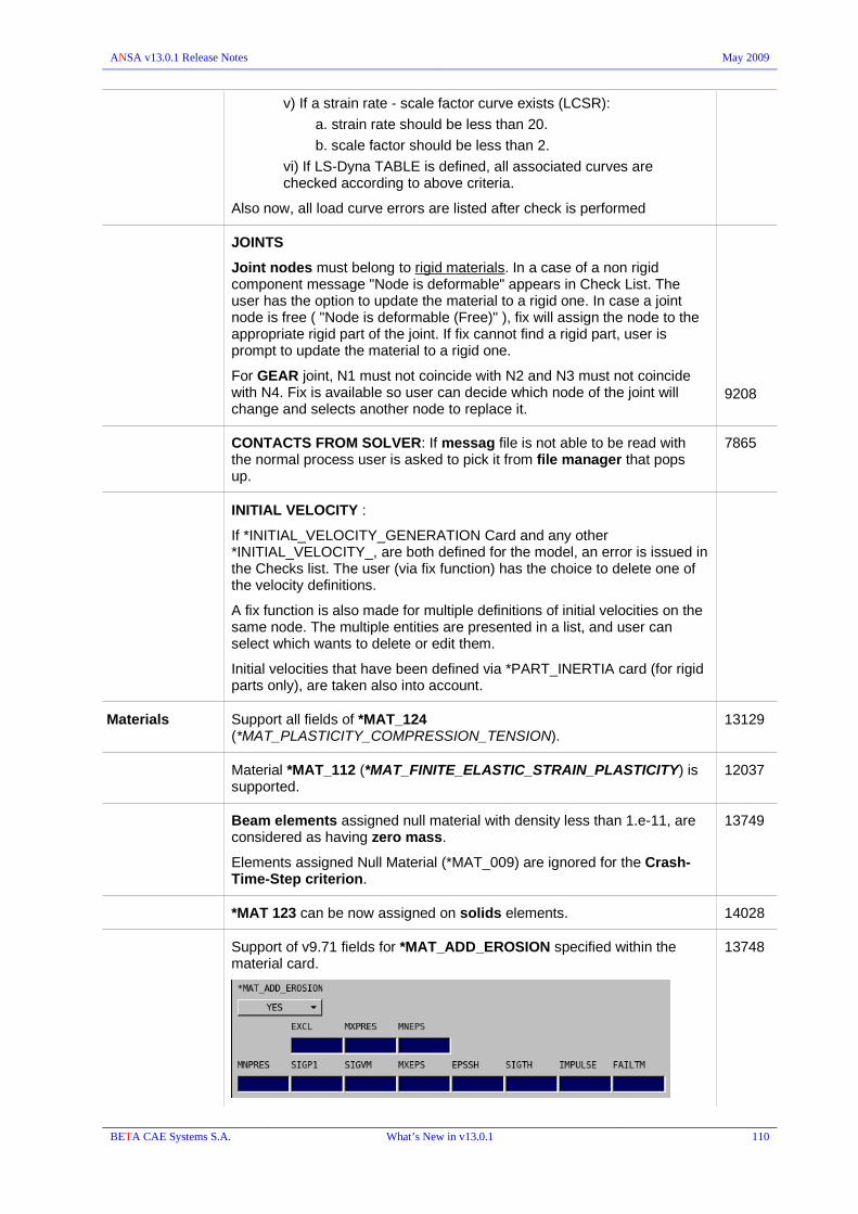
ANSA v13.0.1 Release Notes May 2009
v) If a strain rate - scale factor curve exists (LCSR):
a. strain rate should be less than 20.
b. scale factor should be less than 2.
vi) If LS-Dyna TABLE is defined, all associated curves are checked according to above criteria.
Also now, all load curve errors are listed after check is performed
JOINTS
Joint nodes must belong to rigid materials. In a case of a non rigid component message "Node is deformable" appears in Check List. The user has the option to update the material to a rigid one. In case a joint node is free ( "Node is deformable (Free)" ), fix will assign the node to the appropriate rigid part of the joint. If fix cannot find a rigid part, user is prompt to update the material to a rigid one.
For GEAR joint, N1 must not coincide with N2 and N3 must not coincide with N4. Fix is available so user can decide which node of the joint will change and selects another node to replace it.
9208
CONTACTS FROM SOLVER: If messag file is not able to be read with the normal process user is asked to pick it from file manager that pops up.
7865
INITIAL VELOCITY :
If *INITIAL_VELOCITY_GENERATION Card and any other *INITIAL_VELOCITY_, are both defined for the model, an error is issued in the Checks list. The user (via fix function) has the choice to delete one of the velocity definitions.
A fix function is also made for multiple definitions of initial velocities on the same node. The multiple entities are presented in a list, and user can select which wants to delete or edit them.
Initial velocities that have been defined via *PART_INERTIA card (for rigid parts only), are taken also into account.
Materials Support all fields of *MAT_124 (*MAT_PLASTICITY_COMPRESSION_TENSION).
13129
Material *MAT_112 (*MAT_FINITE_ELASTIC_STRAIN_PLASTICITY) is supported.
12037
Beam elements assigned null material with density less than 1.e-11, are considered as having zero mass.
Elements assigned Null Material (*MAT_009) are ignored for the Crash-Time-Step criterion.
13749
*MAT 123 can be now assigned on solids elements. 14028
Support of v9.71 fields for *MAT_ADD_EROSION specified within the material card.
13748
BETA CAE Systems S.A. What’s New in v13.0.1 110

ANSA v13.0.1 Release Notes May 2009
Support of *MAT_099 (*MAT_SIMPLIFIED_JOHNSON_COOK_ORTHOTROPIC_DAMAGE)
13364
Support of *MAT_163 (*MAT_MODIFIED_CRUSHABLE_FOAM) 13890
DFRESULTANTS
Manual and automatic creation of *DEFINE_SPOTWELD_FAILURE_RESULTANTS
Right click on the top section to Add the default failure card
then right click in the lower section to specify the Pairs.
Selection can be done either form the list or from screen. Moreover, there is an automatic detection “Auto-add from model”.
The *DEFINE_SPOTWELD_FAILURE_RESULTANTS keyword can be created (manually or automatically) only if the Pairs of parts are connected with Solid spotweld elements with MAT100_MAT_SPOTWELD_DAMAGE-FAILURE and OPT 7.0 and *CONTACT_TIED_SURFACE_TO_SURFACE.
10630
BETA CAE Systems S.A. What’s New in v13.0.1 111

ANSA v13.0.1 Release Notes May 2009
DFRICTION
New interface for the creation and management of *DEFINE_FRICTION
Right click on the top section to define the default friction values and then right click to the lower section to Add the Part Pairs either from the list or from the screen.
BETA CAE Systems S.A. What’s New in v13.0.1 112

ANSA v13.0.1 Release Notes May 2009
PAM-CRASH
INPUTVERSION: 2007 & 2008 are supported
Various keywords and options have been added for v2007 and v2008
CONTROL CONTROLS: new window with tabs
11868
Support new options in SUBDF_/ and in SUBRUN (v2007). 10202
Support new option of METRIC_/ (v2007)
Contain the information for the airbag initial metric file in the main file.
10204
Support new options in ECTRL_/
THICKNESS_INTEGRATION options.
METRIC_3D_LOAD (v2007)
10203
Support SENSOR optional keyword in RUNEND/ (v2007) 10200
Support AUTOSLEEP keyword (v2007)
BETA CAE Systems S.A. What’s New in v13.0.1 113

ANSA v13.0.1 Release Notes May 2009
CCTRL : Support new option LEAKFILTER (v2007) 10201
supported control keywords
ANALYSIS : IMPLICIT (v2008)
ECTRL : XROTSHELL, SHELL_FORMULATION, SOLID_FORMULATION
ICTRL : implicit general control cards (v2008)
14229
NODAL ENT CONLO : Added "ISENS" field.
Support new options in DAMP : fields TIDAMP and TFDAMP (v2007)
ISELECT as well as, DRAGCO and ODENS (v2006)
10207
ELEMENTs MEMBR : Support of fiber angles (b1, b2) in MEMBRANE element card. 8194
PLINK :
ON EXISTING NODES : If the picked node is used by an element, i.e. by a shell of the connected Parts, a new node is created at the picked location and used as N1 node of the PLINK.
CENTER PLINKS : If the N1 node of the selected PLINK is shared with other elements, e.g. by a shell of the connected Parts, a warning message appears. These PLINKs are highlighted in orange and won't be moved by hitting the Cancel button while any other selected PLINKs that do not have “shared” nodes will be moved. With OK all PLINKs will be moved.
CONSTRAINTs RBODY type 3: Zero, blank and negative values of mass and principal moments of inertia, are not allowed.
1764
PLOT OUTPUT SECFO : The infinite cross section plane is drawn in the appropriate size so to cut the elements that it refers (via the respective Set). The plane's boundaries are stipple lines and they are colored red if no elements are cut.
11376
THxxx > THNODE | THELE : both options can be defined directly on entities (NODE or ELEMENT respectively) without the need of a set.
AUXILIARIES GEB > GEB_OR - SECFO>Assistant
The GEB_OR that is created by the SECTION>Assistant by picking “properties” and has:
connectivity : #PID
search : PassThrough
11517
BETA CAE Systems S.A. What’s New in v13.0.1 114

ANSA v13.0.1 Release Notes May 2009
Representation : SectionForces
sec_type : PLANE
The set that is created consists of Properties; the ones that were picked and successfully cut.
SENSOR : Support IREVFLG (v2007) 10211
SET
General Entity Selection // GROUP
ANSA SET now supports the DELNOD, DELPART, DELELE, DELGRP via the “DELETED” option created by the Add>Excluded.
RUPMO: Support new cards 5 and 6 in the case of IRUPT=2. 10212
PLY : Support PLY__/_ keyword in all INPUTVERIONs up to 2008.
Edit card of this entity is depended of the INPUTVERSION value in control cards.
10767
Materials Material synchronization from Abaqus material to PamCrash materials 102,103,105 and 106 and vice versa. Data about stress-strain/strain rate behavior are synchronized.
11867
Material type 301 : support new options : IDEABEN=2, SDMPR, IDOFN, IDOFS1, IDOFS2, DSTART, DRELEA, RFAC (v2007)
10196
Material type 223 : option INDOF has been added (v2007) 10198
Support new options of Material type 224 (v2007) including the IFLGP and the user defined constant stiffness fields.
10199
14835
Materials type 212 and 213 : added flag for element elimination strain limit choice in card 6.
10206
Update Material types 107, 117 (v2007). 11237
Rupture model 5 is allowed for Material type 223 (Nonlinear 6-DOF Spring-Beam Element).
13812
Support RMAT definition.
Activate the “Output RMAT” check box in the “Output Parameters” window in order to reference the Material Names within all the PART definitions instead of their Ids.
9046
BETA CAE Systems S.A. What’s New in v13.0.1 115

ANSA v13.0.1 Release Notes May 2009
Visibility of Material Orientation based on the IORT definition in the PART.
12166
CHECK FUNCT : detects errors also in LOOK UP TABLES (LOOKU) 10788
DEPENDENCY
An error is reported if NOT ALL slave nodes of RBODY_0 are selected in ACFLD or DAMP.
A check for the NCOG node of RBODY type 0, is also added. A warning is issued when an acceleration field or a damping group is applied on it. The corresponding fix function gives the ability to delete the nodal entity or to apply the same on the slave nodes of rigid body.
4463
The new check THNOD-THLOC , detects :
i) whether THNOD and THLOC keywords are defined on the same node
ii) CONSISTENCY OF ACFLD SUBTRACTION FOR THLOC OUTPUT (whether two or more different ACLFD keywords are defined on the same THLOC) : fix option allows to add an ACFLD ID in the THLOC card
4462
BETA CAE Systems S.A. What’s New in v13.0.1 116

ANSA v13.0.1 Release Notes May 2009
SUBSTR
New function to create new and manage Substructure definitions
Create a new definition through the SUBSTRUCTURE ANALYSIS CREATOR window. Cutting Planes (already defined by MODEL CUT function or via the New button) should be Added so to define the “User Area volume”.
Visualize the entities of the substructure with the Preview button.
The substructure is created the moment the output is made. ANSA writes the model and following 'cuts' it and writes also the substructure file.
During output all necessary in CONTROLs cards (i.e. SUBRUN) are updated in the substructure file and the SUBDF_/_ definition is automatically created (and written) in the main file.
13433
BETA CAE Systems S.A. What’s New in v13.0.1 117
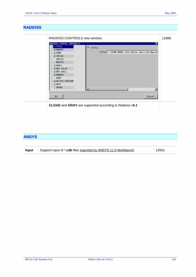
ANSA v13.0.1 Release Notes May 2009
RADIOSS
RADIOSS CONTROLS new window. 11868
CLOAD and GRAV are supported according to Radioss v5.1
ANSYS
Input Support input of *.cdb files exported by ANSYS 11.0 Workbench. 12651
BETA CAE Systems S.A. What’s New in v13.0.1 118

ANSA v13.0.1 Release Notes May 2009
CFD Decks
ANSA provides now DECK module menus for the setup of cases for CFD++, FLUENT (2D and 3D), OpenFOAM, StarCD and UH-3D.
Select in advance the required solver DECK as this will allow the proper display of Property cards for the specification of Boundary Conditions.
It is recommended that ANSA is started with the option -gui cfd
This will allow the better setup of the software interface for CFD pre-processing.
Size Box
The user can control the size of the surface and the volume mesh in selected areas of the model using ANSA Size Boxes.
Size Boxes are flexible entities and can have any orientation or form, thus making mesh size control very precise.
They influence the functions:
- PERIMETERs>A.SPACING [CFD]
- MESH GEN.>CFD
- VOLUMEs>MESHV [Tetra CFD] and [Hexa Interior]
Size Boxes can be created in the SIZE BOX Group of buttons in every CFD Deck.
BETA CAE Systems S.A. What’s New in v13.0.1 119

ANSA v13.0.1 Release Notes May 2009
CFD++ For CFD++ the user can specify in the Shell Property card whether it is of type Boundary for 3D Simulations or Cell for 2D simulations.
OpenFOAM ANSA supports input and output of OpenFOAM v1.4.1 and v1.5 file structures.
The user can specify the solver settings, boundary and initial conditions for a full simulation.
STAR In the STAR deck the user can specify boundary conditions for Star-CD and Star-CCM
e.g. specify the TYPE to e.g. Wall type in Shell Property card
The volume properties can also be specified as fluid or solid.
UH-3D For UH-3D Deck the user can specify in the Shell Property card the boundary condition type and magnitude for:
Surface Temperature
Surface Heat Flux
Mass Flux
Grill Resistance
During output the user can renumber the model.
FLUENT 3D The assigned PIDs of shell (Fluent Faces) and volume (Fluent Cells) elements will be translated into Fluent 3D Zones during the output, maintaining the same ID and name. If there are any spaces in the PID names these will be converted automatically into underscores “_” during output, for Fluent compatibility.
If ANSA detects Properties with identical names, it will rename them (adding a “:1”) during output to avoid conflicts in Fluent.
The type of boundary condition can also be prescribed in the EDIT card or shell and volume Properties.
ANSA supports the input and output of both *.msh and *.cas ascii and binary files.
FLUENT 2D For Fluent 2D meshes the geometry and mesh should be constructed in the z=0 plane.
The PIDs of ANSA shells will be output as fluid 2D cell Zones in Fluent.
Boundary Condition (BCs) names and types along edges (2D Face zones in Fluent) must be specified on ANSA SETs.
If no SETs are created then by default all free boundaries are written in a default-exterior Zone of Wall type, and all interior Faces in a default-interior Zone. If needed they can also be separated later in the solver.
BETA CAE Systems S.A. What’s New in v13.0.1 120

ANSA v13.0.1 Release Notes May 2009
PERMAS
A new Deck module has been added for set-up simulation models for the PERMAS solver.
Directly Input and Output of permas deck files is supported.
Substructure analysis (Multiple Components) can be handled in ANSA via the Includes Manager. Mind that identical Ids are not allowed for similar entities in different components.
Preserve the user specified names of Sets (nodes and elements) 13984
Unique name for Contacts
MEDINA
I/O Support read/write in bif-file of the LS-Dyna keyword *DATABASE_CROSS_SECTION.
13474
Input Import of TRIAV and QUADV elements as MEMBRANES for MEDINA - PAMCRASH.
BETA CAE Systems S.A. What’s New in v13.0.1 121

ANSA v13.0.1 Release Notes May 2009
MORPH
Module's Buttons group modifications.
Synonymous buttons (like SLIDE, OFFSET etc), previously located in different menus, have been unified under the new MODIFICATION group. This group has replaced the former BOX MORPHING menu.
CHECKS: A new group of buttons that hosts the flag buttons (MORPHING, Hi.Li, TRANS, FREEZE , TANG), which are also available during modifications, in the respective window.
There are two modes:
Non-morphing mode: Boxes are simply reshaped in order to better fit to the model's geometry.Morphing mode: Boxes are reshaped and their loaded entities are morphed accordingly.
The MORPHING flag button (CHECKS group), enables the user to toggle between the two aforementioned modes.
A new visibility flag button (MORPHVIEW) has been added in the CHECKS group. Using this button the user can toggle between TOPO and MESH view, while being in MORPH menu.
Morph Settings
Special settings that are used during the Morphing process can be defined through the Windows> Options>Settings>[MORPH] function
''2D morph thickness'' : Defines the virtual thickness of the 2D-Morph Boxes.''Apply extra-fine tolerance'' : Applies extra-fine tolerance to the morphing functions, irrespectively to the current value of tolerance that is used through the OPTIONS>Tolerances function.''Box in Box morphing'' : Activates the Box in Box morphing functionality (see section 22.5.3).''Include morph points in load'' : Enables User to automatically load Morph Control Points, using the LOAD>VISIBLE function.''Ask for morph movement confirmation'' : Activates a Confirmation window after each Morphing action.''Color for linked'' : Activates the Color Editor for the Linked Boxes.
BETA CAE Systems S.A. What’s New in v13.0.1 122

ANSA v13.0.1 Release Notes May 2009
Geometry Morphing
Geometrical entities can now be loaded in Morphing Boxes and morphed accordingly.
The notification : ''GEOMETRY MORPHING INACTIVE'' appears in red color, at the right bottom of the graphic area. Activate the CHECKS>GEO_CHECK function in order to prepare the model (containing FACEs) for Morphing.
During the GEO_CHECK ANSA examines all the loaded Geometrical Faces and performs cuts in areas where they intersect Morphing Boxes. Thus, new faces are produced. These Faces are properly distributed to the appropriate Morphing Boxes. The Geometry Morph window appears listing the loaded Faces and reports any Conflict status due to “cutting” problems. These Faces should be placed into the proper Box by choosing the related Status option [IN || OUT]
All connection entities, 3D curves can be also morphed.
BETA CAE Systems S.A. What’s New in v13.0.1 123

ANSA v13.0.1 Release Notes May 2009
BOXES CYLIND>CONV2BOX
Using this function, it is possible to create hexahedral Boxes in place of cylindrical ones.
Case1. Select a Cylindrical Box without any concentric splits. One hexaedral Box like the one shown below is going to be created:
Case2. Select a Cylindrical Box with concentric splits. ANSA creates five hexahedral Boxes. One Central Box and four more located all around it.
Simultaneously, Morphing Parameters are automatically created in order to control the Length and Radius dimensions of the initial Cylindrical Boxes.
11307
2DMORPH>CONV2BOX: this new function creates 2 Hexahedral Morphing Boxes based on the selected 2D morph entity.
MULTIBOX
The user can create multiple Morphing Boxes in a single step.There are two main options. The Hexa-Block and the O-ring. Using the first, 27 boxes are created in a block-type shape while in the second option, six hexahedral boxes are created around the central box.
An existing Box can be selected as well
8091
BETA CAE Systems S.A. What’s New in v13.0.1 124

ANSA v13.0.1 Release Notes May 2009
OFFSET BOX
A new function to create Morphing Boxes.In this function the user selects an outer (single) Morphing Hatch and defines an offset value. The new Box is connected to the old one by the selected Hatch.
11305
CONTROLS HISTORY
The History during Morphing modifications can be recorded. Morph History States can be recorded through the Confirmation window, after each modification [Rec.Hist]. Additionally, History States can be recorded at any time using the HISTORY function. Using Morph History States, the user can jump at any time to any, previously defined State. Thus, it is quite easy to delete the mistaken Morphing actions.
Using the options under the Create drop menu the user can create a Deformation or a Curved Deformation Morphing Parameters, etc between the selected History States.
User Defined Tangency [EDGES>TANGENCY>USER]
The user is now able to define or modify the orientation of tangency on Morphing Edges, by specifying the desired vector or plane. There is also the option to set an already user-defined tangency orientation, as a Morphing parameter.
11310
BETA CAE Systems S.A. What’s New in v13.0.1 125

ANSA v13.0.1 Release Notes May 2009
CONTROLS NESTED>RB2TONESTED
Nested elements can be created from RBE2s.
The original RBE2 still exist after the creation of the nested element.
PARAM
New Morphing Parameters have been added:
SPIN :
The already known, SPIN modification function can now be performed through a Morphing Parameter.
CURVED_DEFORM :
Using such a parameter the user can perform Morphing, moving along a curve, defined by selected Morph History States. The user defines a factor between 0 and 1 morphs the model parametrically along the defined curve.
USER_TANGENT :
Morphing actions performed by modifying a User Defined Tangency, can also be saved and performed through the relative parameter.
MODIFICATION MOVE
New options and interface for Control Points movement. Transform and Scale options have been added.
11902
11903
BETA CAE Systems S.A. What’s New in v13.0.1 126

ANSA v13.0.1 Release Notes May 2009
DIRECT
The DIRECT function is now available also in the MODIFICATION menu. It is performed on Control Points in order to move them directly.
Select Control Points to be moved. Then define the Control Points that are going to retain position. Finally select the Control Points to move following strictly cursors movements. Press left mouse button in order to lock on the desired position.
FIT>EDGES
A new, friendly and convenient interface helps the user to modify edges and curves selections or to save them, as an EdgeFit Morph Parameter.
As soon as the function is activated the EDGE FIT window appears which is auto updated by the selections.
In case you need to modify a group of curves or edges, select it and press the ''modify'' button. Add more entities using the left button or deselect the already selected using the right one.
Press the ''Save as parameter'' button, to create an EdgeFit parameter based on the defined groups.
Press the ''Apply'' button in order to proceed with Morphing.
The Master/Slave Fit function of older versions, has also been incorporated here. There is also the possibility to add a slave Edge group by right clicking on the relative Master.
ALIGN : control points can be aligned on a plane along a user specified direction.
11909
BETA CAE Systems S.A. What’s New in v13.0.1 127

ANSA v13.0.1 Release Notes May 2009
DIRECT MORPHING
4S.FIT: A selection list appears and automatically updated by the selections made and allows the user to highlight and modify the groups of the selection.
The ABAQUS REFERENCE COORDINATES , the PAM-CRASH METRIC_NODES and LS-DYNA INITIAL FOAM REFERENCE GEOMETRY can be loaded and morphed.
12176
BETA CAE Systems S.A. What’s New in v13.0.1 128

ANSA v13.0.1 Release Notes May 2009
Optimization
Optimization Task
New capabilities in the Simulate Window
Through the simulation window, it is now possible to view an animation of the various steps defined by the design variables.
All the defined design variables are displayed in the upper section. Specify the number of the simulate steps to view in the animation session. Press ''calculate'' button in order the internal states to be calculated. After that, all the animation buttons are enabled and the user can proceed with the animation.
Except viewing the animation, it is also possible to save it in avi format using the ''Rec'' button.
BETA CAE Systems S.A. What’s New in v13.0.1 129
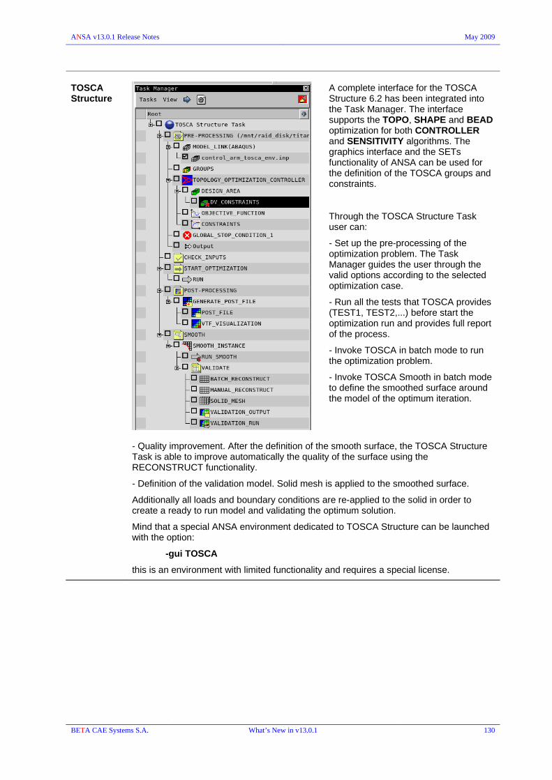
ANSA v13.0.1 Release Notes May 2009
TOSCA Structure
A complete interface for the TOSCA Structure 6.2 has been integrated into the Task Manager. The interface supports the TOPO, SHAPE and BEAD optimization for both CONTROLLER and SENSITIVITY algorithms. The graphics interface and the SETs functionality of ANSA can be used for the definition of the TOSCA groups and constraints.
Through the TOSCA Structure Task user can:
- Set up the pre-processing of the optimization problem. The Task Manager guides the user through the valid options according to the selected optimization case.
- Run all the tests that TOSCA provides (TEST1, TEST2,...) before start the optimization run and provides full report of the process.
- Invoke TOSCA in batch mode to run the optimization problem.
- Invoke TOSCA Smooth in batch mode to define the smoothed surface around the model of the optimum iteration.
- Quality improvement. After the definition of the smooth surface, the TOSCA Structure Task is able to improve automatically the quality of the surface using the RECONSTRUCT functionality.
- Definition of the validation model. Solid mesh is applied to the smoothed surface.
Additionally all loads and boundary conditions are re-applied to the solid in order to create a ready to run model and validating the optimum solution.
Mind that a special ANSA environment dedicated to TOSCA Structure can be launched with the option:
-gui TOSCA
this is an environment with limited functionality and requires a special license.
BETA CAE Systems S.A. What’s New in v13.0.1 130

ANSA v13.0.1 Release Notes May 2009
NASTRAN SOL-200
SOL200 has now been incorporated in the NASTRAN Loadcase under the integrated Design Optimization task item.
BETA CAE Systems S.A. What’s New in v13.0.1 131

ANSA v13.0.1 Release Notes May 2009
SCRIPTING
ANSA_TRANSL
Language &
main features
The ANSA_TRANSL file is now read from the '/home/user/.BETA/ANSA/version_13.0.1/' directory, instead the user home directory (i.e. : /home/user/).
Furthermore, there are some changes in its functionality.
Global code:
the global code is written inside the function CAD_Translate. E.g.
def CAD_Translate()
{
your code
}
Rest code: All the other commands are still written inside the function
def autoexec(), except the buttons creation.
To create user buttons use the command defbutton which creates the button and defines the function simultaneously. The name of the function is the same with the name shown on the button.
Moreover, you can define in which group the button will be created into, by writing the name of the group beside the defbutton command.
Example of creating buttons:
Old ANSA_TRANSL:
def autoexec()
{
AddUserButton("Do Something","DoSomething",1);
}
def DoSomething()
{
your code
}
New ANSA_TRANSL:
defbutton DoSomething()GROUP_NAME
{
your code
}
Thus, with the new way of creating buttons, every time you change the default script the buttons are updated automatically, and only active buttons remain visible.
!!! All ANSA_TRANSL files written in the old manner can be read by ANSA_v13.x, provided that they are in binary format.
BETA CAE Systems S.A. What’s New in v13.0.1 132

ANSA v13.0.1 Release Notes May 2009
The keyword 'const' has been added in scripting language
External files The use of external files in ANSA_v13.x has become more similar to the one in C language.
'#include' statement. The '#include' statement incorporates the contents of a specified file at the same point where the statement appears. Common static functions that exist in different include files can not be treated independently, and therefore only the last one is kept.
'#projectfile' statement. The '#projectfile' statement is another way to use external files within a source file. Its major advantage is that every specified file is treated independently, and thus, any common static functions are allowed.
!!! The '#projectfile' statement in ANSA_v13.x works similarly to the '#include' statement in ANSA_v12.1.x.
File>Script The File > Script button menu has the options to enable script editor and perform other operations related to scripting
Script Editor
Project Window. In this window you can create, control and execute a project. A project is a file that has references to many scripts, incorporated as external files.
View>Editor colors. In the new script editor you can select the colors you will use for each type of text, as well as for the background.
Windows. All the windows of the script editor are handled in the same manner as all ANSA_v13.x windows. Thus they can be visible or not, docked or undocked etc. You can control the script editor windows from the Windows drop down menu.
BETA CAE Systems S.A. What’s New in v13.0.1 133

ANSA v13.0.1 Release Notes May 2009
The File>Script>Default option opens a window where all loaded and added scripts are displayed. The index in front of each path indicates which is the default sequence. Always, the script with zero index is the default.
File>Script>Reload reloads ALL loaded scripts
Command line Command line execution. Execute a script function when starting ANSA with the -exec using brackets in the function's call
-exec function_name()
type any arguments for the function within these brackets.
Script Functions
Function CollectAffectedConnectionEntities has been enhanced.
An additional value 'AllEntities' is supported by the CONNECTION TYPE argument, so that all connecting entities can be collected at once.
An additional value 'AllAffected' is supported by the SEARCH OPTION argument, so that both internal and external connections entities can be collected at once.
New function 'FillGapFreeShells' for 'MESH>FILL>Gap (free)>Shells'. 12321
New function ReferenceEntities. 10606
Extra category "__CONNECTIONS__" added in "TypesInCategory" script function.
11578
New parameter added in script functions: TranslatePart, RotatePart, ScalePart, TransformPart, SymmetryPart, MirrorPartPoint, MirrorPartAxis, MirrorPartPlane.
You can specify the module id offset in the case of Copy-transformations, when creating a new part.
9888
New function FacesConvert converts link faces to normal faces 11742
New function OutputOpenFoamPoints, that outputs only points of the mesh.
BETA CAE Systems S.A. What’s New in v13.0.1 134

ANSA v13.0.1 Release Notes May 2009
New function CopyMatToMdb(). 12145
New functions KinematicsSavePosition and KinematicsMoveToPosition
new session functions added:
SESSION>MESH>SHELL MESH> PARAMETERS>DISTANCE_FROM_SURFACE
SESSION>MESH>SHELL MESH> PARAMETERS>DISTANCE_FROM_SURFACE_PARAM
SESSION>MESH>SHELL MESH> PARAMETERS>DISTANCE_FROM_PERIMETER
SESSION>MESH>SHELL MESH> PARAMETERS>DISTANCE_FROM_PERIMETER_PARAM
to set the respective fix quality parameters through script.
New function RunAllMeshingScenarios, that runs all active scenarios.
New Function RefineElements
New function MorphParamCreate to create parameters from script. 12652
12655
New functions : InputFluentVa, InputStarCDVa, OutputFluent, OutputFluent2D, OutputStarCD
New functions MorphFreezeFlag and MorphMorphingFlag to enable or disable flags
12388
Script function ReconstructShells added : accepts an array of shells and performs reconstruction.
'tanfromnear' flag added in Dach script function. 7450
Enhanced capabilities of the CreateEntityVa script function :
Switching between definition methods 'by node' (or 'by element') and 'by set' using script, is now possible for entities such as the following:
*CONNECTOR MOTION (ABAQUS), SPC (NASTRAN), SPCD (NASTRAN), *BOUNDARY, TYPE=DISPLACEMENT (ABAQUS), D (ANSYS),TIC (NASTRAN),*TEMPERATURE, *INITIAL CONDITIONS, TYPE=TEMPERATURE (ABAQUS),*CONNECTOR LOAD (ABAQUS),SHELL PRESSURE (LSDYNA KWD: *LOAD_SHELL_, PAMCRASH KWD: PREFA, RADIOSS KWD: PLOAD),INITIAL CONDITION, TYPE=STRESS (ABAQUS),PLOAD2 (NASTRAN),DAREA (NASTRAN),INITIAL CONDITION TYPE+ PLASTIC STRAIN (ABAQUS),
5385
BETA CAE Systems S.A. What’s New in v13.0.1 135

ANSA v13.0.1 Release Notes May 2009
LOAD_BEAM (LS_DYNA), PREBM (PAMCRASH),ASET, BSET, CSET, (NASTRAN) VISCOUSFORCE (ABAQUS),TEMP (NASTRAN),*INITIAL CONDITIONS, TYPE=HARDENING, CROSS SECTIONS (ABAQUS),*INITIAL CONDITIONS, TYPE=FIELD (ABAQUS), *FIELD (ABAQUS)*FASTENER (ABAQUS),SPH (LS-DYNA), SPHEL (PAM-CRASH),*CFLUX (ABAQUS),*DFLUX (ABAQUS),*FILM (ABAQUS),CONM2 (NASTRAN), MASS (DYNA , RADIOSS, PAMCRASH, ABAQUS),ACFLD (PAMCRASH),BOUNDARY_CONSTRAINED_MOTION_[NODE/RIGID/RIGID_LOCAL] (LSDYNA),DIS3D / VEL3D / ACC3D / RAN3D / RVE3D / RAC3D (PAMCRASH),IMPDISP / IMPVEL / IMPACC (RADIOSS),*BOUNDARY (ABAQUS),NOLIN (NASTRAN)
Updated LAMINATE scripting functions to handle ABAQUS LAMINATEs.
Added functionality to set the NIP (Number of Integration Points) field (specific to ABAQUS and ANSYS) from script.
Enhanced function GetTaskItemStatus, in order to identify if a script item is disabled.
11858
New Script Functions
- EditCommentsTaskItem (set a comment on a task item)
- GetCommentsTaskItem (get the comment from a task item)
- SetBreakTaskItem ( set break on a task item)
- ClearBreakTaskItem ( remove break from a task item)
11857
In ReplacePart script function the default behavior is the same for connections and connectors.
Function AirbagCreator(int DECK, matrix GROUP_1, matrix GROUP_2, int RECON, element PART or int PART_ID)
Now, the script functions 'AirbagCreator' and 'FillGapFreeShells' can take 'pointer' or 'id' for appropriate 'part' and 'property'.
If the input data are not valid, they will create new 'part' or 'property'.
12321
New script functions RmdblGeomFemSymmetric and RmdblFemFemSymmetric.
11935
Added new script variable argument function "PrintToFileVa".
Pedestrian script function returns six more numbers (total 16). These are the coordinates of target and contact point
New function MorphMultBoxAbsDis for the creation of multiple morph boxes.
BETA CAE Systems S.A. What’s New in v13.0.1 136

ANSA v13.0.1 Release Notes May 2009
New function Compress. Allows also to specify if empty parts/groups will be deleted during geometry compression.
13377
SetViewButton() script function controls also the "LOCK" flag position via SetViewButton("LOCK", "on"); or SetViewButton("LOCK", "off");
Added also script functions:
LoadStoredLockView(char name) - restores model views.
StoreLockView(char name) - stores model views.
13557
New function CheckConnections( matrix InputConnectionsArray, matrix InputCheckDataArray, matrix OutputCheckReportArray );
12597
New function CheckInteriorIntersections( matrix InputEntsMatrix, int fast_run_flag, matrix IntersectedEntsMatrix )
12492
New function xyzIsInsideVolume to find a volume by the coordinates of a point
New functions for tetra mesh volumes by their ID
HexaInteriorbyID(int,int,float)
TetraCFDbyID(int)
TetraFEMbyID(int)
New function CutModelByPlanes(int deck, args...).
Script function: CollectEntities.
An additional argument "prop_from_entities" has been added. In case SEARCH_TYPE is a property, this flag controls if the property must be acquired from the entities referenced by the entities in CONTAINER or not.
12638
CollectEntities works also for Lock Views
New function GetFaceArea( face ) returns the area of the given face .
This area depends on the resolution of the face (the number of the boundary nodes). In order to get more accurate result set a very small CONS Resolution value.
10291
New script functions : ReconstructTetras : runs IMPROVE>RECONS to the tetras
ReconstructViolatingTetras: runs reconstruct on the violating ones plus some zones of tetras specified by the user.
SmoothTetra : runs IMPROVE>SMOOTH on visible tetras and pyramids.
12170
BETA CAE Systems S.A. What’s New in v13.0.1 137
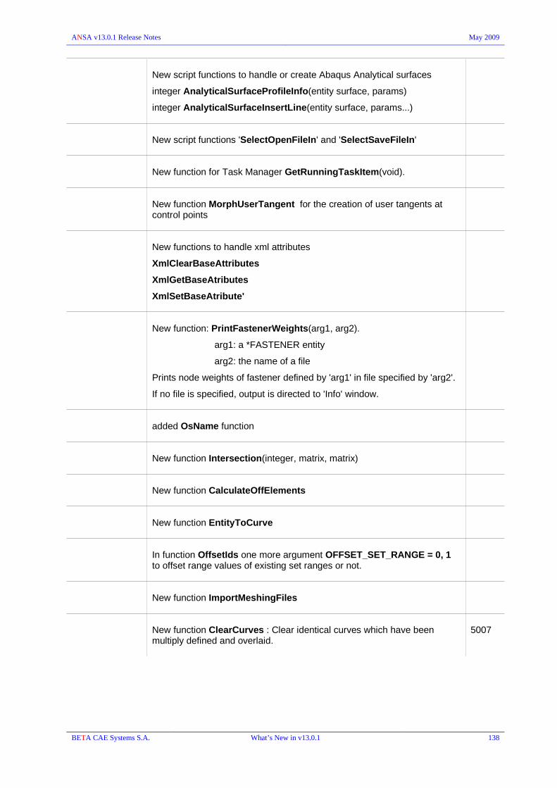
ANSA v13.0.1 Release Notes May 2009
New script functions to handle or create Abaqus Analytical surfaces
integer AnalyticalSurfaceProfileInfo(entity surface, params)
integer AnalyticalSurfaceInsertLine(entity surface, params...)
New script functions 'SelectOpenFileIn' and 'SelectSaveFileIn'
New function for Task Manager GetRunningTaskItem(void).
New function MorphUserTangent for the creation of user tangents at control points
New functions to handle xml attributes
XmlClearBaseAttributes
XmlGetBaseAtributes
XmlSetBaseAtribute'
New function: PrintFastenerWeights(arg1, arg2).
arg1: a *FASTENER entity
arg2: the name of a file
Prints node weights of fastener defined by 'arg1' in file specified by 'arg2'.
If no file is specified, output is directed to 'Info' window.
added OsName function
New function Intersection(integer, matrix, matrix)
New function CalculateOffElements
New function EntityToCurve
In function OffsetIds one more argument OFFSET_SET_RANGE = 0, 1 to offset range values of existing set ranges or not.
New function ImportMeshingFiles
New function ClearCurves : Clear identical curves which have been multiply defined and overlaid.
5007
BETA CAE Systems S.A. What’s New in v13.0.1 138

ANSA v13.0.1 Release Notes May 2009
3. Known Problems resolved in v13.0.1
GENERAL
ANSA terminated when trying to open a previously saved file with "save visible as" option containing an adhesive face. (Error appeared in v12.1.5)
11214
Tolerances window issue fixed. From now on, the pull-down option (draft, middle, fine, extra_fine) is saved in the ANSA defaults file.
9823
Corrected error of Saving mesh parameters. 10903
Corrected AREA and VOLUME calculation. 10291
Comma “,” can not be used instead of dot “.” for decimal point in card fields. Warning message is prompt so to avoid improper input.
9746
Geometry TRANSF.[MOVE] was not able to move Nodes on Macro Areas PERIMETER
13256
MEASURE: Wrong calculation of dx,dy,dz when measuring EDGE-NODE, EDGE-EDGE
13519
FOCUS LOCK: Fix improper selection of Lock view from a “long” pull down menu.
13903
File>Compress All : removed entities that were referenced only in sets, thus these sets remained empty.
14201
File>Open IGES reading problem related to mispositioned parts. 14653
STEP : Problematic CONS error fixed 7927
9912
File> Output CAD
Problem with VDA output : centers of circle curves were confused with the 3d-points and results in a wrong vda output. Now the Circle CENTERs are exported as “PC” instead of “PN”.
8419
STEP : Fixed problems in particular cases 1492
BETA CAE Systems S.A. Known problems resolved in v13.0.1 139

ANSA v13.0.1 Release Notes May 2009
TASK Manager
Abnormal exit caused by selecting “Change” option on a particular script that merged ansa files into Task manager
9959
Fix Method option for Checks>Mesh Quality 13325
Assembly & Connection Manager
PAM PLINK : duplicate and unused mat_302 was created 10019
PAM PLINK : when IDPART field points to an existing property and the “Create Rupture” is enabled; the related material is not changed (i.e. no rupture model is created since this would change the given Property).
10020
TOPO>WELD SPOTs>CONVERT> FE to Adhesive
When Converting RBE3-RBE2-HEXA-RBE2-RBE3 to Adhesive lines the created adhesive lines get now the right connectivity.
11912
Fixed abnormal exit when applying node connections 7746
Thickness-to-Diameter mapping for Spotwelds was not correct for Connections which need projection.
10923
Connections (Lines or Faces) that had their 3D-Curves or Faces deleted are now not shown in CM, nor can they be selected.
4403
Wrong realized representations:
Seamlines > RBE3-HEXA-RBE3
Adhesive lines> RBE3-HEXA-RBE3 & HEXA-Contacts , with options 'Force Ortho Solids' and 'Preserve Width' active.
the rbe3 (or Hexa nodes in contact) are attaching upside down
13891
RBE3-HEXA-RBE3 : Zero Height HEXA
When the connection is between 3 parts or more, and one of HEXAs is of zero height, ANSA still creates the RBE3-HEXA-RBE3. It does not FAIL the connection as it should according to the FAIL ASPECT > option.
7864
Adhesive Lines: Bad Hexa quality in circular adhesive lines. Now a circular curve will produce all its hexas completely symmetrical.
14065
Read Reading an adhesive line from vip2 with H=0 is interpreted in ANSA as H=1.0 13776
BETA CAE Systems S.A. Known problems resolved in v13.0.1 140

ANSA v13.0.1 Release Notes May 2009
BATCH Mesh Manager
Didn't accept holes with diameter smaller than ANSA node matching distance tolerance at reconstruct hole treatment
13772
Left unjoined perimeters on windows xp prof 64. Different results on different machines although the same file and parameters were used.
10313
Abnormal exit on particular case. 10761
More nodes were created along Holes' perimeters. The number of nodes on the holes which were near perimeter was not the same with the node number specified by the Holes treatment tab.
11213
TOPO
FACEs>OFFSET>[FACES] gave bad results 8495
FACEs> SHRINK : fixed error that caused unaccepted result in particular cases. 13456
CROSS SECTs>NEW>MULTICUT: unexpected termination when cutting elements (solids) giving small step length.
13638
CROSS SECTs>NEW>CUT did not perform a proper cut on faces 12211
CROSS SECTs>NEW>MULTICUT: did not calculate sections although this could be achieved by the Cross Section tool.
12259
BETA CAE Systems S.A. Known problems resolved in v13.0.1 141

ANSA v13.0.1 Release Notes May 2009
MESH
PERIMETERs>SLIDE : Error caused distorted hole and abnormal exit.. 12331
13862
PERIMETERs>SLIDE | Batch-Mesh
if the SLIDE function performed onto holes after Batch Mesh the Faces were distorted and re-run of Batch Mesh caused abnormal exit.
3190
GRIDs > ALIGN : abnormal exit on Windows 32bit (in v13.0.0) 13808
14007
GRIDs>MV HOLE> [Slide] : generation of unaccepted elements 7261
SHELL MESH>MAP : in 2nd order MAP mesh the Middle nodes did not always follow the curvature of the face.
11841
(1114)
SHELL MESH>UTIL>[Open Hole] : if a big number was given for the nodes on the hole's perimeter the shape of the hole got deformed.
13706
SHELL MESH> RECONS | WELD SPOTs>MARK
After marking a Hot-Point the mesh Reconstruction caused collapsed shape.
12160
SHELL MESH> RECONS : cased unexpected termination if used on Frozen Macro Areas.
(in v13.0.0)
14422
SHELL MESH>RECONS : When applying reconstruction on some 2nd order shells (part meshed by Batch Mesh) the middle-nodes of not selected elements were moved to the Origin position.
9614
ELEMENTs>SPLIT>Shells : Abnormal exit in particular cases with EDGES selection. 13735
ELEMENTs>TO-SURF>[PER AREA]: fixed error caused abnormal exit (in v13.0.0) 14934
VOLUMEs>IMPROVE> RECONS : caused abnormal exit if applied on tetra mesh having more than 255 tetras per node. (in v13.0.0)
13335
VOLUMEs>EXTRUDE>TRANSLATE : the Distance was not updated by the two picked positions. (in v13.0.0)
14330
VOLUMEs>EXTRUDE>ROTATE : unaccepted results if function applied on 2nd order shell elements. (in v13.0.0)
13822
VOLUMEs>EXTRUDE> SWEEP : abnormal exit and corrupted file creation if saved. (in v13.0.0)
14083
BETA CAE Systems S.A. Known problems resolved in v13.0.1 142

ANSA v13.0.1 Release Notes May 2009
DECKs
SETs Problem with the visibility of set contents: When having a set that contains shells from macros and do Show Only to these shells nothing is visible on screen.
13532
Renumber Unaccepted delay of renumbering during assignment of big number of elements into Include with General numbering rules.
13616
Incorrect renumbering result regarding special rules; the function should be applied twice in order to satisfy the rules.
13667
ABAQUS / ANSYS
Fixed Problem with CONTACT>FLANGES and CHECK>CONTACT ORIENTATION
10550
12614
GEB Fixed problem with the GEB_SB when it is applied in two different (mutually exclusive) parts with the same PID. The two parts had the same PID but only one at a time was active. The set builder got deactivated when one of the sub-group that contained one of the parts got disabled.
11170
CHECK Missing information in check window of "Check Model Data". Now description info is reported in check list.
10224
Checks List : Fix problems related to Highlighting selected items that are reported in the list
12370
14599
Negative volume > Fix/Orient in 2nd order elements, error is fixed 10105
Duplicate : should check 2nd order elements according to their 1st order nodes
8675
Free : 'visible' or 'whole model' blocked ansa 8904
Connectivity : did not work using PERMAS Spotwelds realization
Check Connectivity should also work when the SPRING element is not accompanied by a welding surface (MEDINA case).
8396
BETA CAE Systems S.A. Known problems resolved in v13.0.1 143

ANSA v13.0.1 Release Notes May 2009
ABAQUS
Problem with Edge option of DLOAD : The P,P1,P2,P3,P4 labels of DLOAD for edge-based surfaces (E1,E2,...) were not valid.
DLOADs defined on Shell Edges were written with TYPE='EDLD'/'EDLDNU' instead of 'P'/'PNU'.
6820
*DSLOAD applied on *SURFACE consisting of shells is read in, but exported as *DLOAD. Also, in certain cases, the sign of DLOAD's magnitude was wrongly reversed. This is also fixed.
11991
INPUT Ranges with step different than one were not supported. Now all kind of generate options will be read in properly, without keeping the information of the generation step itself but only the true entities according the the range specification.
10118
CONTACT>FLANGES: Did not recognize contacts between CSHELLS 12614
CONTACT>INFO>NEW : Definition of CONTACT PAIR without "SURFACE INTERACTION specified was accepted. Now it is not accepted.
13215
CHECK Connectivity check reported unconnected parts, although abaqus recognized them connected
13929
If a contact set was defined as SURFACE:
CHECK>CONTACTS would report error "No master/slave set defined".
CHECK>CONTACTS ORIENTATION would report warning "No proximity...".
Those wrong error/warnings are not reported anymore.
7875
LS-DYNA
Input HISTORY : fixed problem regarding DATABASE_HISTORY_BEAM and CONTACT_CABLE_ID
12495
Output Error in output of MAT_ARUP_ADHESIVE (*MAT_169): Card 5 for this material should only be written/available when the EDOT2 field is non-zero.
13457
I/O Material angles definition for membrane shell sections:
Problem in input:In an ELFORM 9 (FI membrane) shell section due to NIP=0, ansa ignored the ICOMP and assigned ICOMP=0. Therefore the layer information was lost. Furthermore, if the user defines NIP=1, the angle B2 was ignored.
Problem in output:Although for NIP=1 ansa allowed to define both B1 and B2, in output the B2 value was not exported.
Now added "0.0" at "NIP" pulldown menu as a value.
input :" " blank field is read as zero.
output :if "NIP" is set to "0.0", B1 and b2 values are written out.
13629
BETA CAE Systems S.A. Known problems resolved in v13.0.1 144

ANSA v13.0.1 Release Notes May 2009
if "NIP" is set to "1.0", only B1 a value is written out.if "NIP" is set to "x.0", B1, B2 ... Bx values are written out. (x!=0,1, x<=30)
D.INFO Different mass report compared with the d3hsp of ls-dyna 13884
*INITIAL_STRESS_SECTION: now allows blank VID (vector id) if the SECTION is of PLANE type / used for solids (v12.1.5)
12702
*CONTROL_SHELL : "PSSTUPD" and "PSNFAIL" changed to set types from plain integers in order to avoid their removal by the File>Compress
13768
PAM-CRASH
File>Compress Now the "Encrypted" MATERIALS and FUNCT are not removed. 13950
Input FTSS H305 v5.1s3 female dummy model:
the input of the female dummy HYBRID III 5th v5.1-s3 did not set the proper hierarchy although the *.pos (positioning) file was read!
11915
MEMBR elements were switched to SHELL if no PART definition existed in the imported file.
8289
Check Model Data: is now able to detect “Invalid Set” used for NSMAS; defined by nodes instead of elements (or Parts)
5367
Model Data: Shell materials with option curve: e.1=<blank> is now allowed
13925
Model Data: PART BEAM with MAT213 and valid "IDSEC", <blank> or zero value for "A" is acceptable.
11089
Rigid Dependency : Node related to Macro Area (geometry node) was ignored by the check regarding the usage of the RBODY NCOG as a connectivity node (used by other element)
14817
D.INFO Different mass report compared with the solver report is fixed 13884
RADIOSS
Input RADIOSS v5.1 : improper interpretation of the /UNIT keyword is fixed. 11464
Check Rigid Dependency: when a Master Node has to be "moved" out of the BOX, ANSA did not check if the candidate position fails inside another neighboring BOX
BETA CAE Systems S.A. Known problems resolved in v13.0.1 145

ANSA v13.0.1 Release Notes May 2009
CFD++
Output CFD++ output problems related to the type of entities within the ansa file i.e. FE-model mesh or Macros mesh and ANSA Volumes mesh
(in v13.0.0)
13588
MEDINA
Wrong output of PERMAS Spotwelds with diameter=0 as Medina bif file: the diameter changed from zero to 20. In this case the diameter of the spotwelds is used as an indicator of a adhesive line.
13860
CROSS SECTION
Wrong result in Cross Section Calculation : CONN_SPOT with was not properly projected to the cross section curves. SpotLines were not properly projected to the cross curves.
9804
ANSA didn't calculate defined cross section.
Solid cross section, though was well defined (CHECK was successful), the section's values were not calculated.
10107
Boundary element distribution: The highest possible number of boundary elements sometimes was not enough to give accurate results. In addition, the distribution in complex areas was not proper enough. Now the upper limit on boundary elements is removed.
13067
SCRIPTING
LaminateLayerNew script function problem (v12.1.4) : It did not take into account the variable "NAME".
10627
GetEntityCardValues was very slow when was applied on curves 8805
CollectEntities: If CONTAINER included Macros and SEARCH_TYPE was Property (eg. PSHELL) the function did not return any property, when 'prop_from_entities' flag was on.
Fix regarding DeleteEntity script function. When deleting shells through script with the use of DeleteEntity() connection entities that referenced the shells' pid lost their representation.
14338
BETA CAE Systems S.A. Known problems resolved in v13.0.1 146