Radically Reducing the Cost and Size of Cellphone RF...
21
Radically Reducing the Cost and Size of Cellphone RF Filters to Fuel the Mobile Revolution How Resonant Developed a Low-Cost, High-Performance Acoustic Wave RF Filter Using Infinite Synthesized Networks (ISN ™ ) Design Techniques WHITEPAPER June 30, 2015
Transcript of Radically Reducing the Cost and Size of Cellphone RF...
Radically Reducing the Cost and Size of Cellphone RF Filters to Fuel the Mobile RevolutionHow Resonant Developed a Low-Cost, High-Performance Acoustic Wave RF Filter Using Infinite Synthesized Networks (ISN™) Design Techniques
WHITEPAPER
June 30, 2015
2
Safe Harbor Statement
This document contains forward-looking statements. The words “believe,” “may,” “will,” “potentially,” “estimate,” “continue,” “anticipate,” “intend,” “could,” “would,” “project,” “plan,” “expect” and similar expressions that convey uncertainty of future events or outcomes are intended to identify forward-looking statements. Forward-looking statements may address the following subjects among others: the status of filter designs under development, the prospects for licensing filter designs upon completion of development, plans for other filter designs not currently in development, potential customers for our designs, the timing and amount of future royalty streams, the expected duration of our capital resources, our hiring plans, the impact of our designs on the mobile device market, and our business strategy. Forward-looking are made as of the date of this document and are inherently subject to risks and uncertainties which could cause actual results to differ materially from those in the forward-looking statements, including, without limitation, the following: our limited operating history (particularly as a new public company); our ability to complete designs that meet customer specifications; the ability of our customers (or their manufacturers)
to fabricate our designs in commercial quantities; our dependence on a small number of customers; the ability of our designs to significantly lower costs as compared to other designs and solutions; the risk that the intense competition and rapid techno-logical change in our industry renders our designs less useful or obsolete; our ability to find, recruit and retain the highly skilled personnel required for our design process in sufficient numbers to support our growth; our ability to manage growth; and general market, economic and business conditions. Additional factors that could cause actual results to differ materially from those anticipated by our forward-looking statements are under the captions “Risk Factors” and “Management’s Discussion and Analysis of Financial Condition and Results of Operations” in our most recent Annual Report (Form 10-K) or Quarterly Report (Form 10-Q) filed with the Securities and Exchange Commission. Forward-looking statements are made as of the date of this document, and we expressly disclaim any obligation or undertaking to update forward-looking statements.
110 Castilian Drive, Suite 100Santa Barbara, CA 93117(805) 308-9803
www.resonant.com
Resonant Inc.

3
TABLE OF CONTENTS
1 Executive Summary . . . . . . . . . . . . . . . . . . . . . . . . . . . . . . . . . . . . . . . . . . . . . . 4
2 Industry Overview. . . . . . . . . . . . . . . . . . . . . . . . . . . . . . . . . . . . . . . . . . . . . . . . 5
3 Resonant® Design Advantage: ISN™ . . . . . . . . . . . . . . . . . . . . . . . . . . . . . . . . 8
4 Key Duplexer Performance Parameters . . . . . . . . . . . . . . . . . . . . . . . . . . . . . . 9
5 Resonant Duplexer Performance Data. . . . . . . . . . . . . . . . . . . . . . . . . . . . . . 12
6 Next Step: Using Resonant’s ISN to Develop a Tunable Filter . . . . . . . . . . 17
Appendix A: Model of a Wireless System . . . . . . . . . . . . . . . . . . . . . . . . . . . 18
Appendix B: Mobile RF Front-End Performance . . . . . . . . . . . . . . . . . . . . . 19
Appendix C: Mobile Filter Technology . . . . . . . . . . . . . . . . . . . . . . . . . . . . . . 20
4
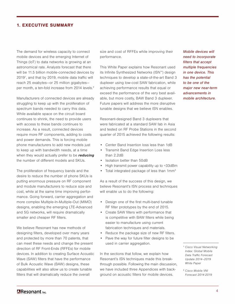
The demand for wireless capacity to connect mobile devices and the emerging Internet of Things (IoT) to data networks is growing at an astronomical rate. Analysts forecast that there will be 11.5 billion mobile-connected devices by 20191, and that by 2019, mobile data traffic will reach 25 exabytes—or 25 million gigabytes— per month, a ten-fold increase from 2014 levels.2
Manufacturers of connected devices are already struggling to keep up with the proliferation of spectrum bands needed to carry this data. While available space on the circuit board continues to shrink, the need to provide users with access to these bands continues to increase. As a result, connected devices require more RF components, adding to costs and power demands. This is forcing mobile phone manufacturers to add new models just to keep up with bandwidth needs, at a time when they would actually prefer to be reducing the number of different models and SKUs.
The proliferation of frequency bands and the desire to reduce the number of phone SKUs is putting enormous pressure on RF component and module manufacturers to reduce size and cost, while at the same time improving perfor-mance. Going forward, carrier aggregation and more complex Multiple-In-Multiple-Out (MIMO) designs, enabling the emerging LTE-Advanced and 5G networks, will require dramatically smaller and cheaper RF filters.
We believe Resonant has new methods of designing filters, developed over many years and protected by more than 70 patents, that can meet these needs and change the present direction of RF Front-Ends (RFFEs) for mobile devices. In addition to creating Surface Acoustic Wave (SAW) filters that have the performance of Bulk Acoustic Wave (BAW) designs, these capabilities will also allow us to create tunable filters that will dramatically reduce the overall
Mobile devices will need to incorporate filters that accept multiple frequencies in one device. This has the potential to be one of the major new near-term advancements in mobile architecture.
1 Cisco Visual Networking Index: Global Mobile Data Traffic Forecast Update 2014–2019 White Paper
2 Cisco Mobile VNI Forecast 2014-2019
size and cost of RFFEs while improving their performance.
This White Paper explains how Resonant used its Infinite Synthesized Networks (ISN™) design techniques to develop a state-of-the-art Band 3 duplexer using low-cost SAW fabrication, while achieving performance results that equal or exceed the performance of the very best avail-able, but more costly, BAW Band 3 duplexer. Future papers will address the more disruptive tunable designs that we believe ISN enables.
Resonant-designed Band 3 duplexers that were fabricated at a standard SAW fab in Asia and tested on RF Probe Stations in the second quarter of 2015 achieved the following results:
• Center Band Insertion loss less than 1dB• Transmit Band Edge Insertion Loss less
than 2.2dB• Isolation better than 50dB• High transmit power capability up to +33dBm• Total integrated package of less than 1mm3
As a result of the success of this design, we believe Resonant’s ISN process and techniques will enable us to do the following:
• Design one of the first multi-band tunable RF filter prototypes by the end of 2015.
• Create SAW filters with performance that is competitive with BAW filters while being easier to manufacture using current fabrication techniques and materials.
• Reduce the package size of new RF filters.• Pave the way for future filter designs to be
used in carrier aggregation.
In the sections that follow, we explain how Resonant’s ISN techniques made this break- through possible. Following the main discussion, we have included three Appendices with back-ground on acoustic filters for mobile devices.
1. EXECUTIVE SUMMARY
5
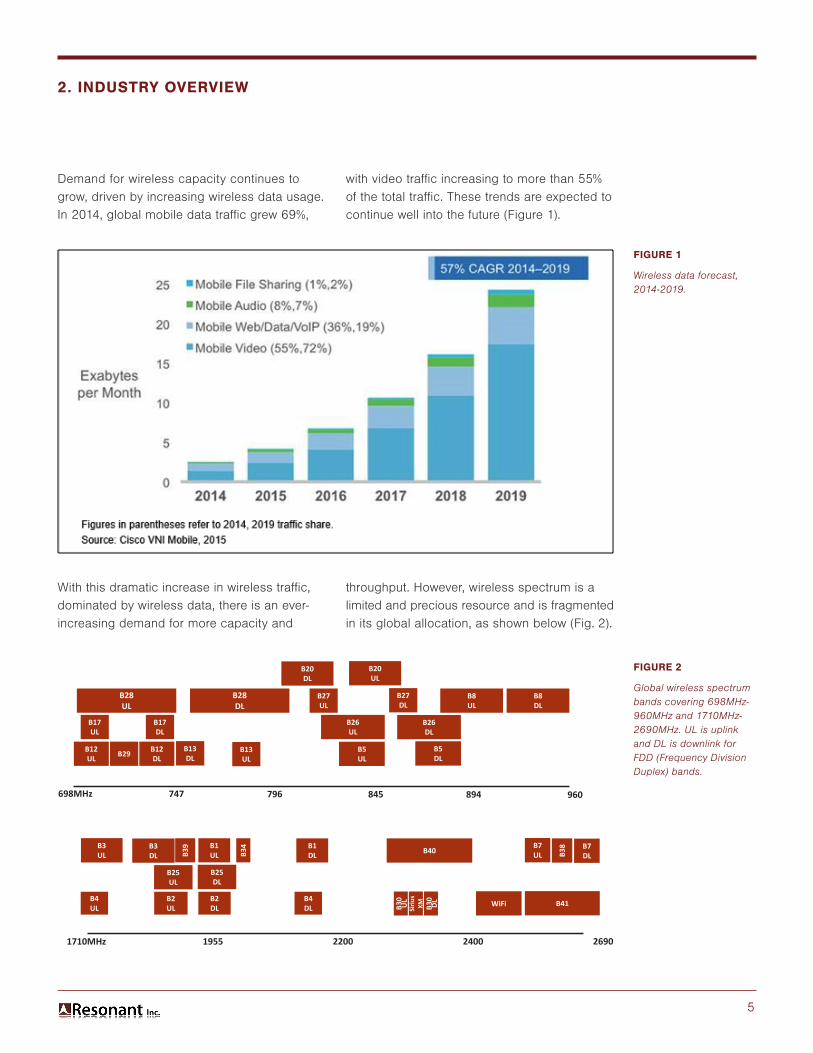
Demand for wireless capacity continues to grow, driven by increasing wireless data usage. In 2014, global mobile data traffic grew 69%,
With this dramatic increase in wireless traffic, dominated by wireless data, there is an ever- increasing demand for more capacity and
FIGURE 1
Wireless data forecast, 2014-2019.
FIGURE 2
Global wireless spectrum bands covering 698MHz-960MHz and 1710MHz-2690MHz. UL is uplink and DL is downlink for FDD (Frequency Division Duplex) bands.
with video traffic increasing to more than 55% of the total traffic. These trends are expected to continue well into the future (Figure 1).
throughput. However, wireless spectrum is a limited and precious resource and is fragmented in its global allocation, as shown below (Fig. 2).
2. INDUSTRY OVERVIEW
B28UL
B17UL
B17DL
B12UL
B12DLB29
B13DL
B13UL
B28DL
B27UL
B27DL
B20DL
B20UL
B26UL
B26DL
B8UL
B8DL
B5UL
B5DL
960894845796747698MHz
B3UL
B3DL
B25UL
B25DL
B4UL
B4DL
B2UL
B2DL
B1UL
B1DLB3
9
B34 B40
B30
UL
B30
DLSiriu
sXM B41WiFi
B7UL
B7DLB3
8
1710MHz 1955 2200 2400 2690
6
LTE (Long Term Evolution), the current wireless data transmission standard, is the first wireless technology to be deployed globally, led by deployments in the U.S. This global deployment has led to cost savings due to increased integration, reduced inventory and optimized supply chain management. However, LTE was developed based upon a priority for wireless data transport, and as such is optimized for high power transmission, which places increased demands on the filters within the RF front-end on mobile devices.
Increasing integration and LTE adoption require:
• More filters in the mobile device (which, in turn, drives the demand for smaller and lower-cost filters).
• High filter performance requirements, particularly with regards to rejection and insertion loss.
• Increasing integration of filters, switches and amplifiers.
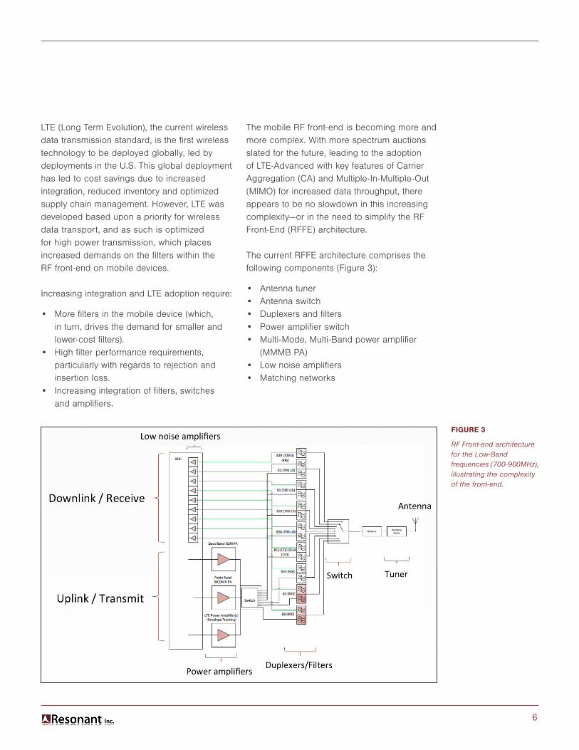
The mobile RF front-end is becoming more and more complex. With more spectrum auctions slated for the future, leading to the adoption of LTE-Advanced with key features of Carrier Aggregation (CA) and Multiple-In-Multiple-Out (MIMO) for increased data throughput, there appears to be no slowdown in this increasing complexity—or in the need to simplify the RF Front-End (RFFE) architecture.
The current RFFE architecture comprises the following components (Figure 3):
• Antenna tuner• Antenna switch• Duplexers and filters• Power amplifier switch• Multi-Mode, Multi-Band power amplifier
(MMMB PA)• Low noise amplifiers• Matching networks
FIGURE 3
RF Front-end architecture for the Low-Band frequencies (700-900MHz), illustrating the complexity of the front-end.
7
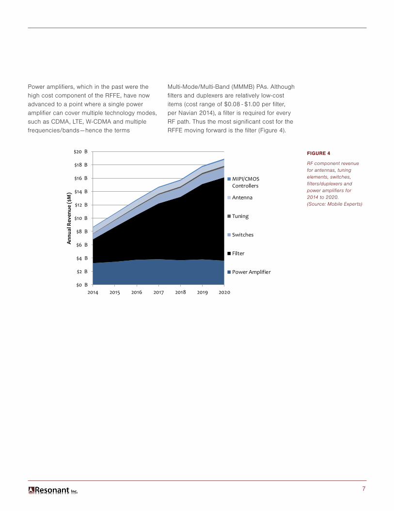
Power amplifiers, which in the past were the high cost component of the RFFE, have now advanced to a point where a single power amplifier can cover multiple technology modes, such as CDMA, LTE, W-CDMA and multiple frequencies/bands—hence the terms
Multi-Mode/Multi-Band (MMMB) PAs. Although filters and duplexers are relatively low-cost items (cost range of $0.08 - $1.00 per filter, per Navian 2014), a filter is required for every RF path. Thus the most significant cost for the RFFE moving forward is the filter (Figure 4).
FIGURE 4
RF component revenue for antennas, tuning elements, switches, filters/duplexers and power amplifiers for 2014 to 2020. (Source: Mobile Experts)
$0 B
$2 B
$4 B
$6 B
$8 B
$10 B
$12 B
$14 B
$16 B
$18 B
$20 B
2014 2015 2016 2017 2018 2019 2020
Ann
ual R
even
ue ($
M)
MIPI/CMOSControllers
Antenna
Tuning
Switches
Filter
Power Amplifier
8
Traditional acoustic wave filter design uses a ladder structure and empirical models (linked to a particular fab manufacturer). Resonant has developed design tools that bring together for the first time the following elements:
• Modern filter theory • Finite element modeling
(both Electro-Magnetic and Acoustic)• Novel optimization algorithms
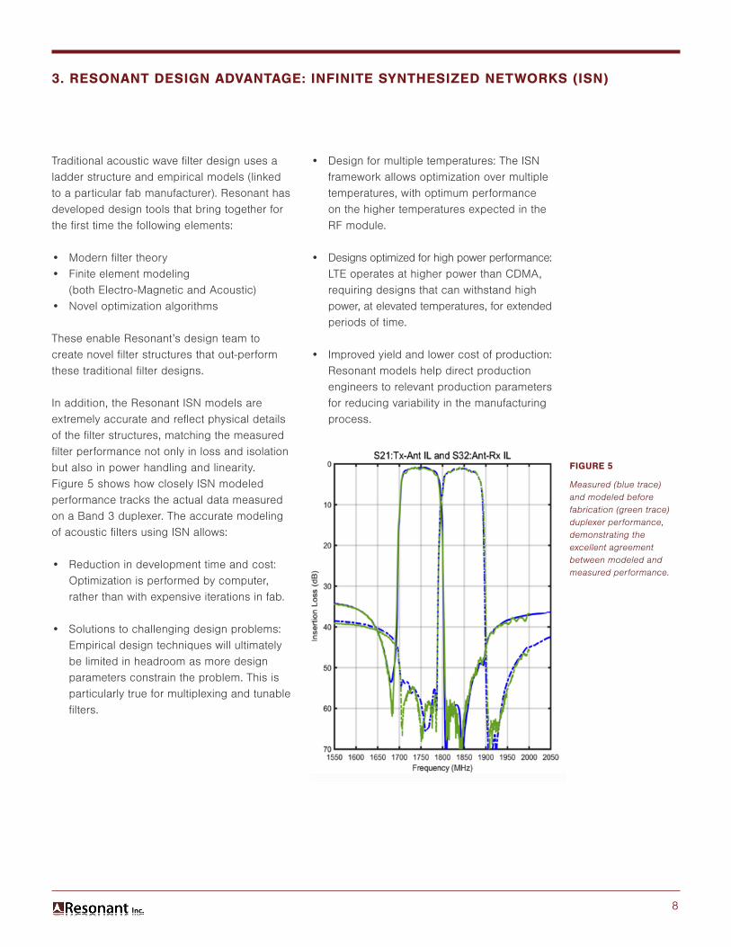
These enable Resonant’s design team to create novel filter structures that out-perform these traditional filter designs. In addition, the Resonant ISN models are extremely accurate and reflect physical details of the filter structures, matching the measured filter performance not only in loss and isolation but also in power handling and linearity. Figure 5 shows how closely ISN modeled performance tracks the actual data measured on a Band 3 duplexer. The accurate modeling of acoustic filters using ISN allows: • Reduction in development time and cost:
Optimization is performed by computer, rather than with expensive iterations in fab.
• Solutions to challenging design problems: Empirical design techniques will ultimately be limited in headroom as more design parameters constrain the problem. This is particularly true for multiplexing and tunable filters.
FIGURE 5
Measured (blue trace) and modeled before fabrication (green trace) duplexer performance, demonstrating the excellent agreement between modeled and measured performance.
• Design for multiple temperatures: The ISN framework allows optimization over multiple temperatures, with optimum performance on the higher temperatures expected in the RF module.
• Designs optimized for high power performance: LTE operates at higher power than CDMA, requiring designs that can withstand high power, at elevated temperatures, for extended periods of time.
• Improved yield and lower cost of production: Resonant models help direct production engineers to relevant production parameters for reducing variability in the manufacturing process.
3. RESONANT DESIGN ADVANTAGE: INFINITE SYNTHESIZED NETWORKS (ISN)
9
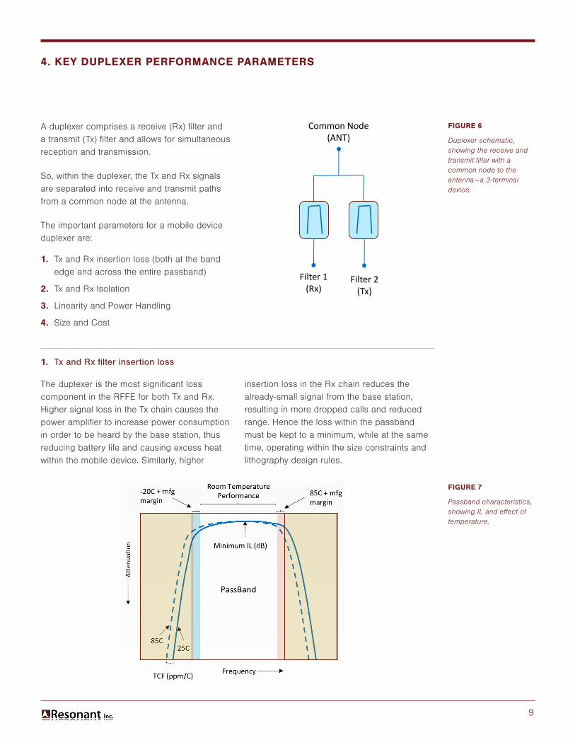
A duplexer comprises a receive (Rx) filter and a transmit (Tx) filter and allows for simultaneous reception and transmission.
So, within the duplexer, the Tx and Rx signals are separated into receive and transmit paths from a common node at the antenna.
The important parameters for a mobile device duplexer are:
1. Tx and Rx insertion loss (both at the band edge and across the entire passband)
2. Tx and Rx Isolation
3. Linearity and Power Handling
4. Size and Cost
FIGURE 6
Duplexer schematic, showing the receive and transmit filter with a common node to the antenna—a 3-terminal device.
FIGURE 7
Passband characteristics, showing IL and effect of temperature.
1. Tx and Rx filter insertion loss
The duplexer is the most significant loss component in the RFFE for both Tx and Rx. Higher signal loss in the Tx chain causes the power amplifier to increase power consumption in order to be heard by the base station, thus reducing battery life and causing excess heat within the mobile device. Similarly, higher
4. KEY DUPLEXER PERFORMANCE PARAMETERS
Common Node(ANT)
Filter 1(Rx)
Filter 2(Tx)
insertion loss in the Rx chain reduces the already-small signal from the base station, resulting in more dropped calls and reduced range. Hence the loss within the passband must be kept to a minimum, while at the same time, operating within the size constraints and lithography design rules.
10
The losses vary across the passband, but are highest at the band edges, so the band edge insertion loss represents one of the most critical characteristics of any filter.
In addition to the performance characteristics at room temperature, the filter must allow for operation over a large temperature range (a spread of more than 100°C). The piezoelectric materials used for these applications are susceptible to changes in temperature, producing frequency shifts for devices. The Temperature Coefficient in Frequency (TCF) is comprised of two components:
TCF = TCE + TCV Equation
where, TCE is the Temperature Coefficient of Expansion, ppm/C, and TCV is the Temperature Coefficient of Velocity, ppm/C.
For those bands with high rejection close to the passband, operation over the large spread in temperature can only be achieved by using temperature compensation (TC) techniques to reduce TCF. These techniques add to the cost of the process. Typical ratio for these costs are:
BAW ~ 2 x TC-SAW and TC-SAW ~ 2 x SAW
2. Tx and Rx Isolation
In the case of a duplexer, the most significant source of noise is leakage of Tx into Rx or Rx signals into the Tx path. The parameter that characterizes this leakage is isolation, defined as the amount of signal passing between the Tx and Rx ports of a duplexer. In the case of LTE (4G), this specification has become more important and the isolation requirement has been increased. In order to maximize data rates, LTE operates at higher power levels than previous generations of wireless technology. (This is different from CDMA, which operated
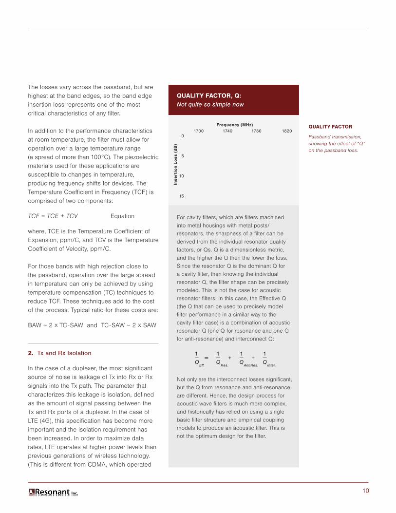
QUALITY FACTOR
Passband transmission, showing the effect of “Q” on the passband loss.
QUALITY FACTOR, Q: Not quite so simple now
For cavity filters, which are filters machined
into metal housings with metal posts/
resonators, the sharpness of a filter can be
derived from the individual resonator quality
factors, or Qs. Q is a dimensionless metric,
and the higher the Q then the lower the loss.
Since the resonator Q is the dominant Q for
a cavity filter, then knowing the individual
resonator Q, the filter shape can be precisely
modeled. This is not the case for acoustic
resonator filters. In this case, the Effective Q
(the Q that can be used to precisely model
filter performance in a similar way to the
cavity filter case) is a combination of acoustic
resonator Q (one Q for resonance and one Q
for anti-resonance) and interconnect Q:
Not only are the interconnect losses significant,
but the Q from resonance and anti-resonance
are different. Hence, the design process for
acoustic wave filters is much more complex,
and historically has relied on using a single
basic filter structure and empirical coupling
models to produce an acoustic filter. This is
not the optimum design for the filter.
Frequency (MHz)
Inser1on
Loss (dB
) Increasing Q
1 1 1 1— = — + — + —Q Q Q Q Eff. Res. AntiRes. Inter.
0
5
10
15
1700 1740 1780 1820Frequency (MHz)
Inse
rtio
n Lo
ss (
dB
)
11
close to the noise floor). Hence, higher isolation is required in order to maintain the same noise levels as 3G, for the now much more substantial 4G signals.
3. Linearity and Power Handling
Linearity and power handling are related. However, non-linear behavior generates noise (circuits generally become more non-linear at higher power levels), which degrades SINR. “Power handling” is the ability to survive high power signals over an extended time period and is a reliability issue.
Linearity and power handling issues are complicated by the fact that more and more of the bands used for LTE are at higher
frequency. Higher frequency requires smaller dimensions for acoustic resonators, and as a consequence, the effective power density in the metal is higher. These higher power densities increase the likelihood of failures due to thermal or fatigue issues.
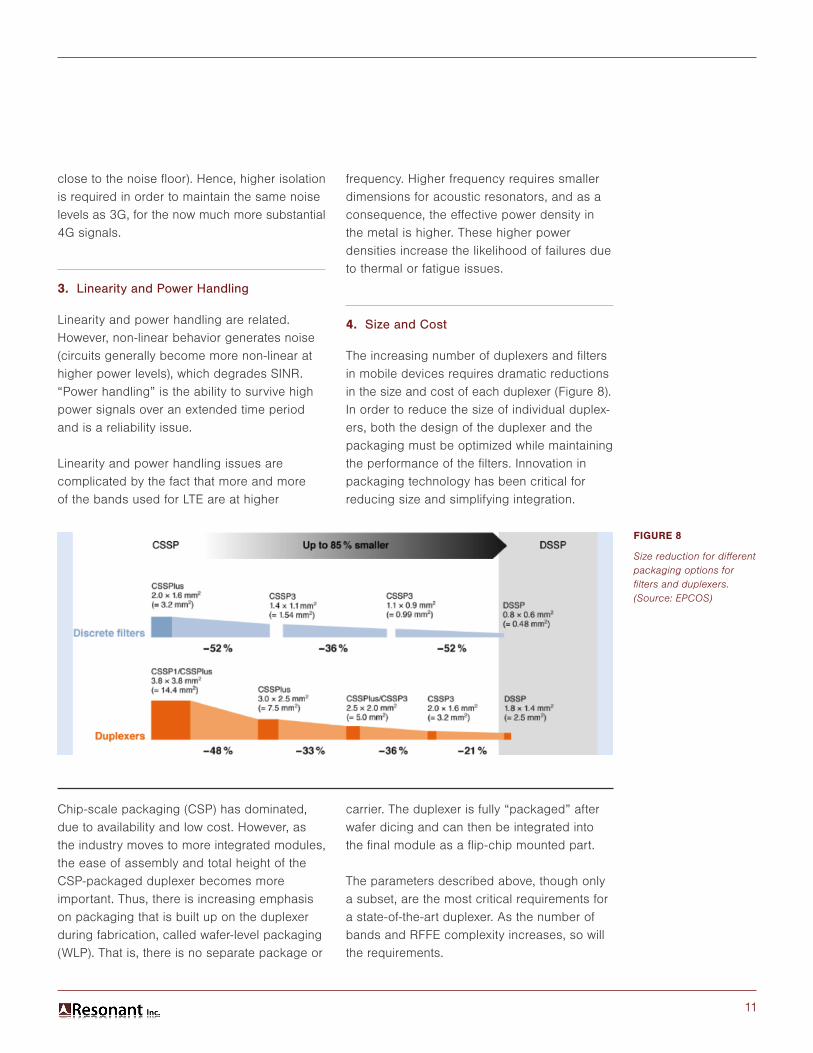
4. Size and Cost
The increasing number of duplexers and filters in mobile devices requires dramatic reductions in the size and cost of each duplexer (Figure 8). In order to reduce the size of individual duplex-ers, both the design of the duplexer and the packaging must be optimized while maintaining the performance of the filters. Innovation in packaging technology has been critical for reducing size and simplifying integration.
FIGURE 8
Size reduction for different packaging options for filters and duplexers. (Source: EPCOS)
Chip-scale packaging (CSP) has dominated, due to availability and low cost. However, as the industry moves to more integrated modules, the ease of assembly and total height of the CSP-packaged duplexer becomes more important. Thus, there is increasing emphasis on packaging that is built up on the duplexer during fabrication, called wafer-level packaging (WLP). That is, there is no separate package or
carrier. The duplexer is fully “packaged” after wafer dicing and can then be integrated into the final module as a flip-chip mounted part.
The parameters described above, though only a subset, are the most critical requirements for a state-of-the-art duplexer. As the number of bands and RFFE complexity increases, so will the requirements.

12
The key performance metrics discussed in the previous section become critical for those bands where the separation between receive and transmit frequencies (duplexer gap) is small, and the frequency itself is high (>1.7GHz). These are often referred to as the “hard” bands. Table 1 below shows the FDD bands ordered based upon a Figure of Merit (FOM) that reflects the difficulty of producing a duplexer for the band.
The smaller the FOM, the more difficult and complex the duplexer. In Table 1, Bands (22 thru 7) shown in orange traditionally use BAW filters, while bands 28 thru 20 (in blue) predominantly use TC-SAW and the remainder (11 thru 29, in green) use SAW. The one exception to the overall trend is Band 13 (in grey), which has unique requirements due to the narrow bandwidth and adjacent public safety band, requiring steep rejection unrelated to duplexer gap.
5. RESONANT DUPLEXER PERFORMANCE DATA
LTE Band Uplink DownlinkNumber (MHz) (MHz) FOM
22 3410 - 3500 3510 - 3600 90 10 0.03225 1850 - 1915 1930 - 1995 65 15 0.1203 1710 - 1785 1805 -1880 75 20 0.1492 1850 - 1910 1930 - 1990 60 20 0.1747 2500 - 2570 2620 - 2690 70 50 0.275
28 703 - 748 758 - 803 45 10 0.2958 880 - 915 925 - 960 35 10 0.311
26 814 - 849 859 - 894 35 10 0.33520 832 - 862 791 - 821 30 11 0.44411 1427.9 - 1452.9 1475.9 - 1500.9 25 23 0.62812 698 - 716 728 - 746 18 12 0.9235 824 - 849 869 - 894 25 20 0.9319 1749.9 - 1784.9 1844.9 - 1879.9 35 60 0.9451 1920 - 1980 2110 - 2170 60 130 1.059
24 1625.5 - 1660.5 1525 - 1559 35 66.5 1.22821 1447.9 - 1462.9 1495.5 - 1510.9 15 32.6 1.43130 2305 - 2315 2350 - 2360 10 35 1.50127 807 - 824 852 - 869 17 28 1.96517 704 - 716 734 - 746 12 18 2.06931 452.5 - 457.5 462.5 - 467.5 5 5 2.17419 830 - 845 875 - 890 15 30 2.32618 815 - 830 860 - 875 15 30 2.36714 788 - 798 758 - 768 10 20 2.57113 777 - 787 746 - 756 10 21 2.74010 1710 - 1770 2110 - 2170 60 340 2.92123 2000 - 2020 2180 - 2200 20 160 3.8106 830 - 840 875 - 885 10 35 4.0824 1710 - 1755 2110 - 2155 45 355 4.082
15 1900 - 1920 2600 - 2620 20 680 15.04416 2010 - 2025 2585 - 2600 15 560 16.19729 n/a 717 - 728 11 n/a n/a
Passband Width (MHz)
Duplexer Gap (MHz)
TABLE 1
FDD Bands ordered by degree of difficulty (FOM).
Duplexer Gap 1FOM = x Passband Width Frequency
13
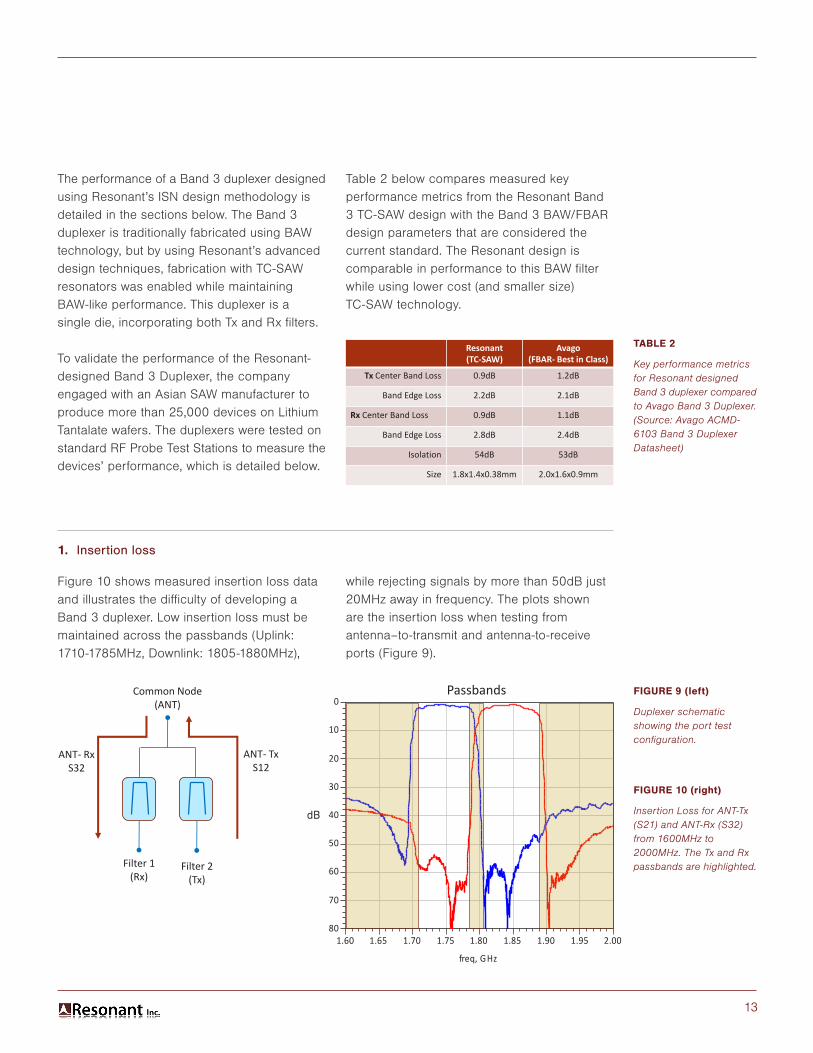
The performance of a Band 3 duplexer designed using Resonant’s ISN design methodology is detailed in the sections below. The Band 3 duplexer is traditionally fabricated using BAW technology, but by using Resonant’s advanced design techniques, fabrication with TC-SAW resonators was enabled while maintaining BAW-like performance. This duplexer is a single die, incorporating both Tx and Rx filters.
To validate the performance of the Resonant- designed Band 3 Duplexer, the company engaged with an Asian SAW manufacturer to produce more than 25,000 devices on Lithium Tantalate wafers. The duplexers were tested on standard RF Probe Test Stations to measure the devices’ performance, which is detailed below.
Table 2 below compares measured key performance metrics from the Resonant Band 3 TC-SAW design with the Band 3 BAW/FBAR design parameters that are considered the current standard. The Resonant design is comparable in performance to this BAW filter while using lower cost (and smaller size) TC-SAW technology.
Resonant(TC-SAW)
Avago(FBAR- Best in Class)
Tx Center Band Loss 0.9dB 1.2dB
Band Edge Loss 2.2dB 2.1dB
Rx Center Band Loss 0.9dB 1.1dB
Band Edge Loss 2.8dB 2.4dB
Isolation 54dB 53dB
Size 1.8x1.4x0.38mm 2.0x1.6x0.9mm
TABLE 2
Key performance metrics for Resonant designed Band 3 duplexer compared to Avago Band 3 Duplexer. (Source: Avago ACMD-6103 Band 3 Duplexer Datasheet)
FIGURE 9 (left)
Duplexer schematic showing the port test configuration.
FIGURE 10 (right)
Insertion Loss for ANT-Tx (S21) and ANT-Rx (S32) from 1600MHz to 2000MHz. The Tx and Rx passbands are highlighted.
1. Insertion loss
Figure 10 shows measured insertion loss data and illustrates the difficulty of developing a Band 3 duplexer. Low insertion loss must be maintained across the passbands (Uplink: 1710-1785MHz, Downlink: 1805-1880MHz),
while rejecting signals by more than 50dB just 20MHz away in frequency. The plots shown are the insertion loss when testing from antenna–to-transmit and antenna-to-receive ports (Figure 9).
1.65 1.70 1.75 1.80 1.85 1.90 1.951.60 2.00
-70
-60
-50
-40
-30
-20
-10
-80
0
freq, GHz
dB(S
(2,1
))dB
(S(3
,2))dB
Passbands
dB
Common Node(ANT)
Filter 1(Rx)
Filter 2(Tx)
ANT- RxS32
ANT- TxS12

14
The low loss performance is best shown by the insertion loss detail within the passband (Figure 11).
The transmit insertion loss is less than 2.1dB across the entire band with a minimum insertion loss of less than 1dB. In addition, the temperature shift over a 125°C temperature spread from -25°C to +100°C is small, such that there is very little change in performance over the entire temperature range (Figure 12). In fact, by using the Resonant ISN design tools, the design can be optimized over multiple temperatures, with a priority placed on the higher temperatures, as this is more realistic for real-world applications.
The shift in frequency of 3.4MHz represents a change of 17ppm/C. The duplexer is designed to take this variation into account.
dB
Rx PassbandTx Passband
-20C
-100C
25C
FIGURE 11
Insertion Loss for ANT-Tx (S21) from 1690MHz to 1810MHz and ANT-Rx (S32) from 1790MHz to 1900MHz.
FIGURE 12
Insertion Loss for Low frequency edge of Band 3 Tx passband, measured at -20C, 25C and 100C.
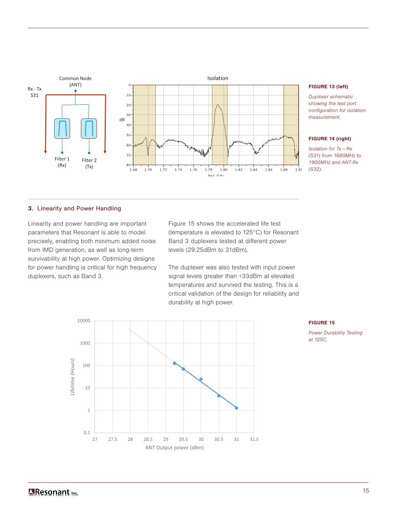
2. Isolation
Figure 14 shows the isolation of Tx to Rx and Rx to Tx. The most important metric is that transmit signals from the PA must be attenuated. High-power transmit signals incident on the receiver will generate IMD noise and degrade performance on the Rx path.
The Band 3 duplexer designed by Resonant has isolation better than 53dB across the transmit band.
Tx Passband
dB
1.70 1.71 1.72 1.73 1.74 1.75 1.76 1.77 1.78 1.79 1.801.69 1.81
-7
-6
-5
-4
-3
-2
-1
-8
0
freq, G Hz
dB(S
(2,1
))
1.80 1.81 1.82 1.83 1.84 1.85 1.86 1.87 1.88 1.891.79 1.90
-7
-6
-5
-4
-3
-2
-1
-8
0
freq, G Hz
dB(S
(3,2
))dB
Rx PassbandTx Passband
dB
1.70 1.71 1.72 1.73 1.74 1.75 1.76 1.77 1.78 1.79 1.801.69 1.81
-7
-6
-5
-4
-3
-2
-1
-8
0
freq, G Hz
dB(S
(2,1
))
1.80 1.81 1.82 1.83 1.84 1.85 1.86 1.87 1.88 1.891.79 1.90
-7
-6
-5
-4
-3
-2
-1
-8
0
freq, G Hz
dB(S
(3,2
))dB
Rx Passband
-‐20C
100C
25C
15
Common Node(ANT)
Filter 1(Rx)
Filter 2(Tx)
Rx - TxS31
1.70 1.72 1.74 1.76 1.78 1.80 1.82 1.84 1.86 1.881.68 1.90
-70
-60
-50
-40
-30
-20
-10
-80
0
freq, G Hz
dB(S
(3,1
))dB
Isolation
dB
FIGURE 13 (left)
Duplexer schematic showing the test port configuration for isolation measurement.
FIGURE 15
Power Durability Testing at 125C.
FIGURE 14 (right)
Isolation for Tx – Rx (S31) from 1680MHz to 1900MHz and ANT-Rx (S32).
3. Linearity and Power Handling
Linearity and power handling are important parameters that Resonant is able to model precisely, enabling both minimum added noise from IMD generation, as well as long-term survivability at high power. Optimizing designs for power handling is critical for high frequency duplexers, such as Band 3.
Figure 15 shows the accelerated life test (temperature is elevated to 125°C) for Resonant Band 3 duplexers tested at different power levels (29.25dBm to 31dBm).
The duplexer was also tested with input power signal levels greater than +33dBm at elevated temperatures and survived the testing. This is a critical validation of the design for reliability and durability at high power.
0.1
1
10
100
1000
10000
27 27.5 28 28.5 29 29.5 30 30.5 31 31.5
Life
time
(Hou
rs)
ANT Output power (dBm)
16
4. Size and Cost
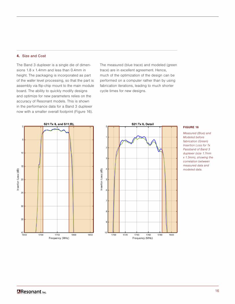
The Band 3 duplexer is a single die of dimen-sions 1.8 x 1.4mm and less than 0.4mm in height. The packaging is incorporated as part of the wafer level processing, so that the part is assembly via flip-chip mount to the main module board. The ability to quickly modify designs and optimize for new parameters relies on the accuracy of Resonant models. This is shown in the performance data for a Band 3 duplexer now with a smaller overall footprint (Figure 16).
The measured (blue trace) and modeled (green trace) are in excellent agreement. Hence, much of the optimization of the design can be performed on a computer rather than by using fabrication iterations, leading to much shorter cycle times for new designs.
FIGURE 16
Measured (Blue) and Modeled before fabrication (Green) Insertion Loss for Tx Passband of Band 3 duplexer (size 1.7mm x 1.3mm), showing the correlation between measured data and modeled data.

17
Using Resonant’s ISN design tools, we have developed a state-of-the-art Band 3 duplexer that utilizes low-cost Surface Acoustic Wave (SAW) fabrication, rather than the more costly and larger Bulk Acoustic Wave (BAW) process traditionally used for Band 3.
Carrier Aggregation and more complex MIMO (for LTE-Advanced and 5G) demand dramatically reduced size and cost for the filters in the RF Front-End (more than 5x size reduction). In parallel with designing smaller size, lower-cost fixed filters (such as the Band 3 duplexer described in this White Paper) Resonant is in the process of developing a multi-state, reconfigurable tunable filter which shares acoustic resonators to generate multiple passbands.
Our ISN technology has enabled us to produce a prototype tunable design that operates in multiple bands. The goal of a tunable filter is to replace multiple filters with a single tunable filter, saving both cost and valuable space. Now that we have demonstrated the commercial viability of ISN design techniques, we expect to complete the development of a prototype tunable RF filter by the end of 2015.
6. NEXT STEP: USING ISN TO DEVELOP A TUNABLE FILTER
18
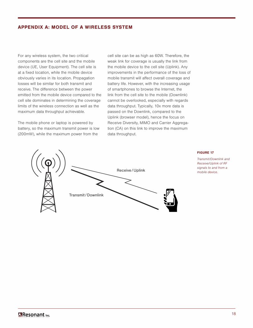
For any wireless system, the two critical components are the cell site and the mobile device (UE, User Equipment). The cell site is at a fixed location, while the mobile device obviously varies in its location. Propagation losses will be similar for both transmit and receive. The difference between the power emitted from the mobile device compared to the cell site dominates in determining the coverage limits of the wireless connection as well as the maximum data throughput achievable.
The mobile phone or laptop is powered by battery, so the maximum transmit power is low (200mW), while the maximum power from the
cell site can be as high as 60W. Therefore, the weak link for coverage is usually the link from the mobile device to the cell site (Uplink). Any improvements in the performance of the loss of mobile transmit will affect overall coverage and battery life. However, with the increasing usage of smartphones to browse the Internet, the link from the cell site to the mobile (Downlink) cannot be overlooked, especially with regards data throughput. Typically, 10x more data is passed on the Downlink, compared to the Uplink (browser model), hence the focus on Receive Diversity, MIMO and Carrier Aggrega-tion (CA) on this link to improve the maximum data throughput.
APPENDIX A: MODEL OF A WIRELESS SYSTEM
FIGURE 17
Transmit/Downlink and Receive/Uplink of RF signals to and from a mobile device.Receive/Uplink
Transmit /Downlink
19
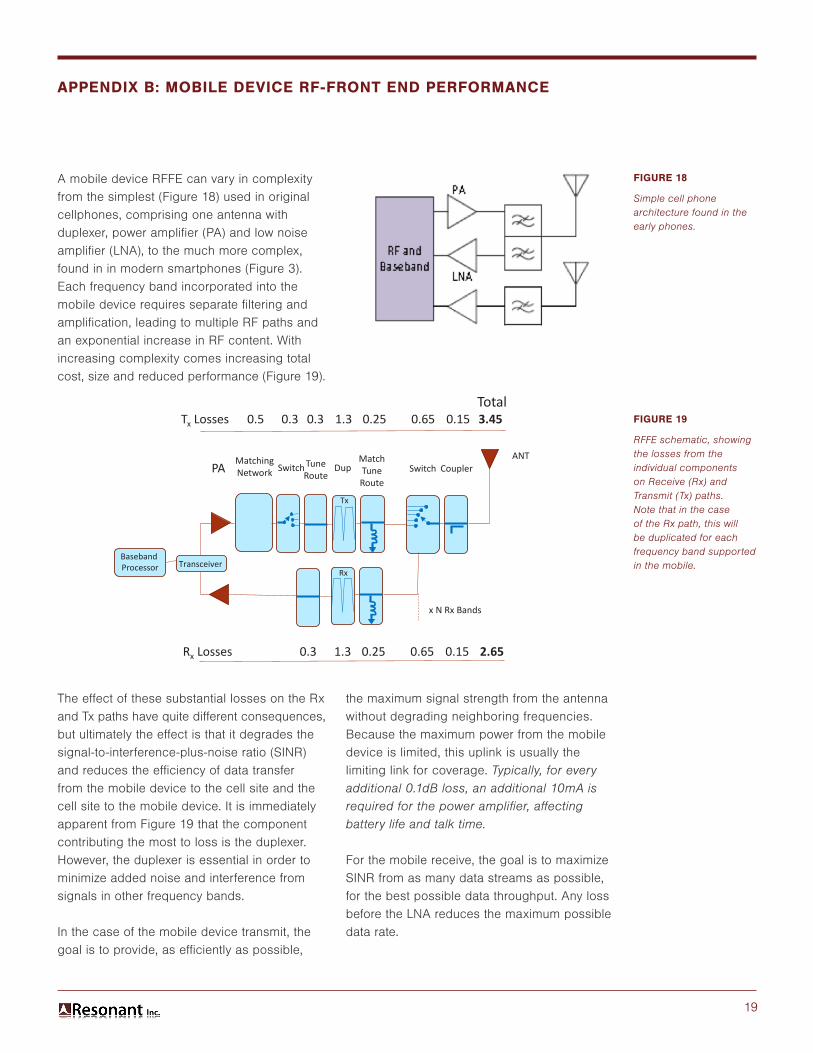
A mobile device RFFE can vary in complexity from the simplest (Figure 18) used in original cellphones, comprising one antenna with duplexer, power amplifier (PA) and low noise amplifier (LNA), to the much more complex, found in in modern smartphones (Figure 3). Each frequency band incorporated into the mobile device requires separate filtering and amplification, leading to multiple RF paths and an exponential increase in RF content. With increasing complexity comes increasing total cost, size and reduced performance (Figure 19).
The effect of these substantial losses on the Rx and Tx paths have quite different consequences, but ultimately the effect is that it degrades the signal-to-interference-plus-noise ratio (SINR) and reduces the efficiency of data transfer from the mobile device to the cell site and the cell site to the mobile device. It is immediately apparent from Figure 19 that the component contributing the most to loss is the duplexer. However, the duplexer is essential in order to minimize added noise and interference from signals in other frequency bands.
In the case of the mobile device transmit, the goal is to provide, as efficiently as possible,
the maximum signal strength from the antenna without degrading neighboring frequencies. Because the maximum power from the mobile device is limited, this uplink is usually the limiting link for coverage. Typically, for every additional 0.1dB loss, an additional 10mA is required for the power amplifier, affecting battery life and talk time.
For the mobile receive, the goal is to maximize SINR from as many data streams as possible, for the best possible data throughput. Any loss before the LNA reduces the maximum possible data rate.
APPENDIX B: MOBILE DEVICE RF-FRONT END PERFORMANCE
FIGURE 18
Simple cell phone architecture found in the early phones.
FIGURE 19
RFFE schematic, showing the losses from the individual components on Receive (Rx) and Transmit (Tx) paths. Note that in the case of the Rx path, this will be duplicated for each frequency band supported in the mobile.Transceiver
PAMatchingNetwork Switch Dup
MatchTuneRoute
Switch CouplerANT
Tx Losses 0.3
TuneRoute
0.3 1.3 0.25 0.65 0.15
BasebandProcessor
x N Rx Bands
Rx Losses 0.3 1.3 0.25 0.65 0.15
Tx
Rx
3.45
2.65
Total
Total
0.5
20
The challenge for mobile filter technology is to provide high performance filtering (low loss and high interference protection) in a very small footprint, at low cost. The first mobile phones used dielectric-based filters, which were expensive and bulky. Only through the development of acoustic wave filters could the size and cost allow realization of the compact filters necessary for modern mobile phones.
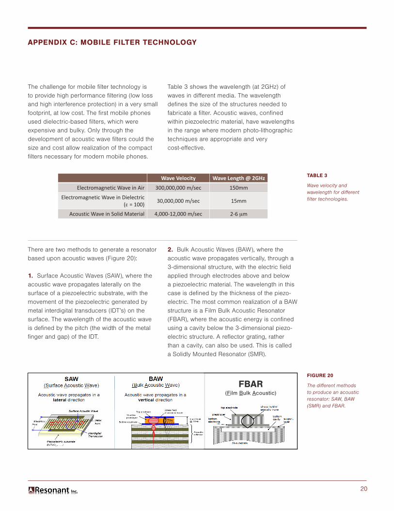
There are two methods to generate a resonator based upon acoustic waves (Figure 20):
1. Surface Acoustic Waves (SAW), where the acoustic wave propagates laterally on the surface of a piezoelectric substrate, with the movement of the piezoelectric generated by metal interdigital transducers (IDT’s) on the surface. The wavelength of the acoustic wave is defined by the pitch (the width of the metal finger and gap) of the IDT.
Table 3 shows the wavelength (at 2GHz) of waves in different media. The wavelength defines the size of the structures needed to fabricate a filter. Acoustic waves, confined within piezoelectric material, have wavelengths in the range where modern photo-lithographic techniques are appropriate and very cost-effective.
2. Bulk Acoustic Waves (BAW), where the acoustic wave propagates vertically, through a 3-dimensional structure, with the electric field applied through electrodes above and below a piezoelectric material. The wavelength in this case is defined by the thickness of the piezo-electric. The most common realization of a BAW structure is a Film Bulk Acoustic Resonator (FBAR), where the acoustic energy is confined using a cavity below the 3-dimensional piezo-electric structure. A reflector grating, rather than a cavity, can also be used. This is called a Solidly Mounted Resonator (SMR).
APPENDIX C: MOBILE FILTER TECHNOLOGY
Wave Velocity Wave Length @ 2GHz
Electromagnetic Wave in Air 300,000,000 m/sec 150mm
Electromagnetic Wave in Dielectric( = 100) 30,000,000 m/sec 15mm
Acoustic Wave in Solid Material 4,000-12,000 m/sec 2-6 m
TABLE 3
Wave velocity and wavelength for different filter technologies.
FIGURE 20
The different methods to produce an acoustic resonator: SAW, BAW (SMR) and FBAR.
FBAR(Film Bulk Acoustic)
21
Each method has advantages and disadvan-tages:
• SAW filters are low cost because of the simple lithography, but at high frequency the metal fingers are narrow and lithography becomes more difficult. Advances in manufacturing processes have enabled a greater use of SAW filers in higher frequency bands.
• BAW filters are more costly, but have higher performance at high frequency.
In the case of SAW resonators, the substrate itself is piezoelectric, and hence determines many of the characteristics. Consequently, the single crystal substrate material (LiTaO3 (Lithium Tantalate), LiNbO3 (Lithium Niobate,
Quartz) and the orientation of the substrate surface are important in determining the filter parameters (frequency, coupling coefficient, losses, and spurious modes).
For BAW resonators, the substrate is single crystal silicon, and so is available in large diameter and has the potential for further integration with other front-end components. The filter parameters are determined by the piezoelectric, which is a deposition layer, in the 3D structure.
For both SAW and BAW resonators, two resonances are produced, a resonance and an anti-resonance, and the separation of these resonances both limit and determine the bandwidth of filter that is achievable.