
Practical Hints for the Installation of Strain Gages
63
HBM Publication English Practical Hints for the Installation of Strain Gages by Karl Hoffmann L1421-2.0 en
Transcript of Practical Hints for the Installation of Strain Gages

HBM PublicationEnglish
Practical Hints for the Installation of Strain Gages
by Karl Hoffmann
L142
1-2.
0 en

Practical Hints for the Installation of Strain Gages
L1421-2.0 en
Important noticeWe know from experience that the processes and materials mentioned or recommended in this brochure are reliable and suitable for the purpose described and also conform to the state of the art. They are to be understood as guidance and advice for the use of strain gages. However, as applications are so diverse and conditions so complex, it is not possible for either Hottinger Baldwin Messtechnik GmbH or the author to offer any guarantees, nor can they be held liable in any way whatsoever for any claims derived therefrom. For critical cases, we recommend an initial test that takes into account the special conditions applicable to you. Please note in particular the safety and working regulations, applicable safety data sheets can be obtained from the manufacturers for many of the products mentioned here.Neither the publisher not the author are aware of any industrial property rights that would be affected by these implementations, although this cannot be excluded with certainty.Note: The numbers in square brackets (e.g. [1]) relate to additional literature, see Section 6, Bibliography, Page 60.
We would be happy to provide you with more information about our program. You can obtain detailed information documentation on the techniques and processes used, as well as on the corresponding equipment. Our expert engineers in the field service are always at your service for detailed consultations. They will also be happy to provide you with non-binding proposals for the solution of your measurement technology problems.
© 1979 4., completely revised and updated version 2011
Printed in the Federal Republic of Germany
All rights reserved. No part of this document may be reproduced in whole or in part in any form or by any means, or translated, without the express written permission of the publishers. Extracts may be photocopied for personal use.

Contents
Contents Page
1 Introduction . . . . . . . . . . . . . . . . . . . . . . . . . . . . . . . . . . . . . . . . . . . . . . . 5
2 The installation of SG . . . . . . . . . . . . . . . . . . . . . . . . . . . . . . . . . . . . . . . 82.1 Task and function of the bonding material . . . . . . . . . . . . . . . . . . . . . 82.2 Type of bonding materials . . . . . . . . . . . . . . . . . . . . . . . . . . . . . . . . . 92.3 Characteristics of the various HBM SG adhesives . . . . . . . . . . . . . 142.4 Application of adhesives . . . . . . . . . . . . . . . . . . . . . . . . . . . . . . . . . 15
2.4.1 Bonding surface preparation for metals . . . . . . . . . . . . . . . . . 162.4.2 Bonding surface preparation for non-metals . . . . . . . . . . . . . 222.4.3 Use of SG in medical technology. . . . . . . . . . . . . . . . . . . . . . 252.4.4 SG preparation. . . . . . . . . . . . . . . . . . . . . . . . . . . . . . . . . . . . 262.4.5 Bonding process . . . . . . . . . . . . . . . . . . . . . . . . . . . . . . . . . . 322.4.6 Precautionary measures . . . . . . . . . . . . . . . . . . . . . . . . . . . . 38
3 Connecting the cables . . . . . . . . . . . . . . . . . . . . . . . . . . . . . . . . . . . . . 393.1 Soldering tools, soldering materials, connection materials . . . . . . . 39
3.1.1 Soldering irons . . . . . . . . . . . . . . . . . . . . . . . . . . . . . . . . . . . . 393.1.2 Soldering tips . . . . . . . . . . . . . . . . . . . . . . . . . . . . . . . . . . . . . 393.1.3 Solders (soft solders) . . . . . . . . . . . . . . . . . . . . . . . . . . . . . . . 403.1.4 Fluxes . . . . . . . . . . . . . . . . . . . . . . . . . . . . . . . . . . . . . . . . . . 413.1.5 Solder terminals . . . . . . . . . . . . . . . . . . . . . . . . . . . . . . . . . . . 423.1.6 Lead material . . . . . . . . . . . . . . . . . . . . . . . . . . . . . . . . . . . . . 42
3.2 Practical tips. . . . . . . . . . . . . . . . . . . . . . . . . . . . . . . . . . . . . . . . . . . 463.2.1 Soldering tips . . . . . . . . . . . . . . . . . . . . . . . . . . . . . . . . . . . . . 463.2.2 Hints for cable connection . . . . . . . . . . . . . . . . . . . . . . . . . . . 49
4 Intermediate tests . . . . . . . . . . . . . . . . . . . . . . . . . . . . . . . . . . . . . . . . . 514.1 Visual inspection . . . . . . . . . . . . . . . . . . . . . . . . . . . . . . . . . . . . . . . 514.2 SG contact resistance . . . . . . . . . . . . . . . . . . . . . . . . . . . . . . . . . . . 514.3 Connection cable resistance . . . . . . . . . . . . . . . . . . . . . . . . . . . . . . 514.4 SG insulation resistance . . . . . . . . . . . . . . . . . . . . . . . . . . . . . . . . . 514.5 Connection cable insulation resistance . . . . . . . . . . . . . . . . . . . . . . 52
L1540-2.0 de 3

Hinweise zur Installation von DMS, Contents
5 Measuring point protection . . . . . . . . . . . . . . . . . . . . . . . . . . . . . . . . . 535.1 Hints for the use and structure of protective covers for SG
measuring points . . . . . . . . . . . . . . . . . . . . . . . . . . . . . . . . . . . . . . . 545.2 Common covering agents . . . . . . . . . . . . . . . . . . . . . . . . . . . . . . . . 55
6 Bibliography . . . . . . . . . . . . . . . . . . . . . . . . . . . . . . . . . . . . . . . . . . . . . 60
4 L1540-2.0 de

Introduction
1 Introduction
Strain gages (SG) are designed to measure strains. The results of such measurements can be used to make statements about the material stresses of the measurement object, about the nature and amount of forces acting on the measurement object, etc. An SG can however only perform the required task if the strain to be measured is transferred faultlessly and without loss. This requires an intimate connection between the SG and the measurement object. The required intimate, full contact connection between the measurement object and SG can only be achieved with special adhesives and methods. Some bonding materials and methods are limited to special applications, e.g. ceramic bonding materials in high temperature installations and spot welding on steel work applications; both areas however also require special SG.The quality of the installation has a long-term influence on the achievable measurement errors and uncertainty. It can be said that an SG in the delivery condition is not yet a complete measurement device and must be installed by the user in order to be ready for use.SG and their installation form a unit. Which part of this combination contributes to errors and to which extent can only be determined through comprehensive comparison measurements with other combinations. You should therefore always use the recommended installation materials and methods, unless you have the test equipment described in [1] and can implement the extremely comprehensive and expensive tests yourself. All the components that form the “measuring point”, such as SG, bonding material, covering agents and other accessories have been tested in comprehensive test series for their effectiveness, compatibility with each other and reliability before being accepted into the delivery range of a manufacturer; their properties are constantly monitored on the basis of quality assurance. Their reliability is therefore not open to question if used properly. No guarantee can therefore understandably be given if they are combined with other, foreign products or if processed using different methods.It is not just the bonding material itself, but also the careful and expert application which contributes to success or failure. The instructions for use supplied with the adhesives contain all necessary information and instructions, and must be followed with the utmost accuracy.Careful preparation is required, especially for larger projects, so that a measurement can be implemented optimally. This requires, in addition to objective test planning, personnel disposition. Only skilled personnel can ensure success. HBM has for many years endeavored to pass on the necessary specialist knowledge, including in cooperation with institutes of engineering and technician training. The specialist information that the installation technician must be provided with includes all data regarding type,
L1421-2.0 en 5

Installation of strain gages, Introduction
scope and application of the required measuring equipment. The test leader must provide clear information here based on his knowledge of the task and the test conditions. Table 1-1 provide various key points for this purpose.The installation technician requires the following principal data:• Installation location and measuring grid direction on the object (installation
drawing, measuring points diagram)
• Circuit diagram, cable plan
• SG type being used
• The bonding method and material (e.g. a special adhesive type)
• Lead material (cable type, cross-section, insulation, etc.)
• Protective measures against mechanical, chemical, electrical, thermal or other influences on the measuring point or leads
Decision aids can be found in the technical information, e.g. in [17] and [18], or in the technical literature. The question regarding suitable safety measures is sometimes difficult to answer when complex disturbing and influencing factors apply, or can be answered only after comprehensive trials under actual conditions. The highest level of reliability is required of the installation technician, together with specialist knowledge, skill and experience, as the quality of the installation is a prerequisite for reliable measurement results.
6 L1421-2.0 en
Introduction
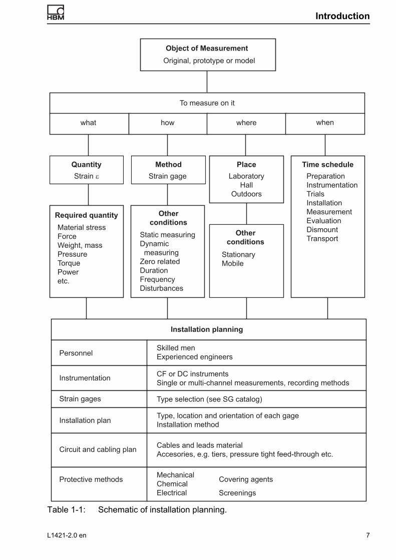
Table 1-1: Schematic of installation planning.
QuantityStrain gage
Object of MeasurementOriginal, prototype or model
To measure on it
what how where when
Method Place Time scheduleStrain ε Laboratory
HallOutdoors
PreparationInstrumentationTrialsInstallation MeasurementEvaluationDismountTransport
Required quantity Otherconditions
Otherconditions
Material stressForceWeight, massPressureTorquePoweretc.
Static measuringDynamic measuringZero relatedDurationFrequencyDisturbances
StationaryMobile
Installation planning
Skilled menExperienced engineers
CF or DC instrumentsSingle or multi-channel measurements, recording methods
Type selection (see SG catalog)
Personnel
Instrumentation
Strain gages
Type, location and orientation of each gageInstallation method
Cables and leads materialAccesories, e.g. tiers, pressure tight feed-through etc.
Installation plan
Circuit and cabling plan
Protective methods MechanicalChemicalElectrical
Covering agents
Screenings
L1421-2.0 en 7
Installation of strain gages, The installation of SG
2 The installation of SG
2.1 Task and function of the bonding material
The bonding materials have the task of firmly attaching the SG to the surface of the measurement object and transfer the deformation of the object without loss to the SG. Various conditions and influences, and the application options, require different bonding materials and application methods. Bonding is the most important factor. The particular advantages of this connection methods, with regards to SG installation applications, are: • The possibility of connecting different materials, even dissimilar ones.
Depending on the type of adhesive, connection is implemented at room temperature or higher temperatures.
• No influence on the materials to be connected (some restrictions may apply for plastics).
• Chemically-hardening adhesives (only these are still used in SG technology) are characterized by low moisture absorption.
• Control of working speed through selection of different adhesive types or curing conditions (hot or cold curing).
• Higher specific electrical resistance contributes to higher insulation resistance between SG and component.
The adhesion of bonded parts is based on the adhesion between the adhesive and the surfaces wetted by the adhesive. Adhesion is mainly based on the attractive forces between neighboring molecules. The contribution from mechanical bonding of the adhesive in the pores of the roughened surfaces or from capillary action is very small. The increase in bonding stability observed in moderately rough surfaces is due to the increase in effective contact surface caused by roughening and not “mechanical adhesion”.
Note 2.1-1:The reasons for adhesion are very complicated and only partially explained [2], [3]. A significant contribution to bonding forces comes from adsorption (also called “secondary valency bonds”), some from chemical bonding (primary valency bonds) and other energy sources. Various types of bonding mechanisms in the adsorption sector are summarized under the term “van der Waal's forces” and are basically distinguished by three types of reciprocal orientation effects: • The dipole moment (Keesom forces). If positive and negative charges in a molecule are
distributed asymmetrically, the molecule is neutral but will have a dipole moment, i.e. it will be polar. Neighboring molecules will try to align their dipole moment so that the
8 L1421-2.0 en

The installation of SG
positively charged side of a molecule will face towards the negatively charged side of a molecule and vice versa. The average range of the Keesom forces is 0.4 to 0.5 nm (4-5 Å).
• The induction effect (Debye forces). Interactions also result if the charge centre of gravity in the electrical field of a molecule is shifted by the inductive effect of an outer field (e.g. another molecule). Unlike Keesom forces, one particle has a permanent dipole and the other an induced dipole moment in the case of Debye forces. The average range of the Debye forces is 0.35 to 0.45 nm (3.5-4.5 Å).
• The dispersion effect (London forces). This effect may be explained by wave mechanic considerations whereby the continuously changing probability density for the positions of the electric charges in a system of two particles oscillating “in phase” induces a constant dipole moment. The average range of the London forces is 0.35 to 0.45 nm (3.5-4.5 Å).
The so-called “hydrogen bridge bond” holds a special position in the van der Waal's forces. It is also based on the interaction of oriented dipoles, but has the peculiarity that the positive pole of at least one dipole is formed by a hydrogen atom. The average range of the hydrogen bridge is 0.26 to 0.3 nm (2.6-3 Å). The percentage of chemical bond forces (primary valency bonds) has not yet been fully explained. It appears however that these force contribute less to the adhesive forces.
2.2 Type of bonding materials
Both the working conditions at the installation site and the various requirements for the bonding material performance, particularly with regards to operating temperature, have led to various types of bonding materials being available. The same applies to the SG itself. This gives rise to matches between various SG series and adhesive types with optimal properties within a limited application range. The application limits are defined by the component with the narrowest performance range in other combinations with different performances. In addition, there are SG and bonding materials whose combination is not possible for technological reasons. Please refer to the recommendations in the brochures and technical data sheets.
Note 2.2-1:It is essential not to use any adhesives other than the recommended adhesive. SG adhesives must fulfill different requirements than general adhesives. This is why they are generally based on special developments or modifications of commercial adhesives. That an SG simply adheres to an object is not a sufficient criterion to evaluate the suitability of the adhesive for measurement purposes, it must also ensure a faultless transmission of the object strain. This requires more in-depth investigations (SG tests according to [1] automatically include the adhesives).
Bonding materials can be differentiated as follows regarding the application technology:
L1421-2.0 en 9

Installation of strain gages, The installation of SG
• Cold-curing adhesivesThese can be easily applied and do not require much effort. There are single-component adhesives that start curing when e.g. air is excluded (“anaerobic”) and two-component adhesives that must be mixed before application. Adhesive with very short reaction times are also called “superglues”. Their preferred field of application is in experimental stress analysis.
• Hot-curing adhesivesThese adhesives can only be used where the test object can be brought up to the required curing temperature. This is generally possible in the manufacture of transducers, but also where SG can be installed before machine assembly or where machines can be dismounted for SG installation. In contrast to cold-curing adhesive, the hot-curing adhesive offer a wider application range at higher temperatures and are suitable, in combination with precision SG, for meeting the generally higher accuracy requirements in transducer production.
• Spot welding This is one of the simpler installation methods. It requires very little equipment (a small spot welder), little preparation and training. However, it is not often used for the following reasons:
• Special SG are needed, and there are not many types available.
• Weldable SG can only be manufactured down to certain sizes, further limiting their application range.
• The measurement object must consist of a weldable material. On certain objects, this type of application is not permitted despite welding suitability as there is a danger of micro-corrosion, e.g. on highly stressed components of steam boilers, austenitic steels, etc.
• The measurement object must be so strong (thick) that the stress distribution is not modified by the relatively large restoring force of the SG, i.e. no noticeable strain impedance should occur.
Table 2-2 on page 12f. provides an overview of the SG bonding materials offered by HBM and their main technical and processing-related data, Table 2-1 contains an explanation of the letters and symbols.
10 L1421-2.0 en

The installation of SG
Letter code SG properties
Y, C, V Polyimide carrier
G, K Phenolic fiberglass carrier
A, U PEEKF carrier
E PEEK carrier
S Metallic carrier (weldable SG)
Symbol Significance
Optimal combination of SG and bonding material
Suitable, but sacrificing a part of the SG or bonding material temperature range
– Unsuitable combination
Table 2-1: Explanation of letters and symbols in Table 2-2.
L1421-2.0 en 11
Installation of strain gages, The installation of SG
+400°C
ox.)
on SG
ducers
ducers
-55°C
ucers
-200°C 0°C +200°C
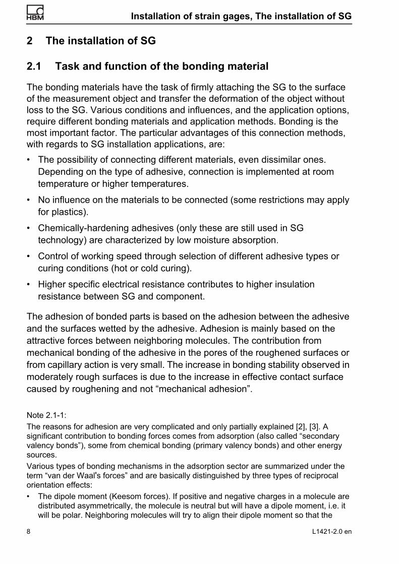
Bonding material
Main application areas
Base material
Useful temperature range (apprfor zero-point related 1 for non zero-point related 2 measurements
1) With zero-point related measurement, the measured values are referenced to the zero point (usually static measurements).
2) With non non zero-point related measurement, the zero point can fluctuate, only the dynamic part is important (dynamic measurements).
X60 superglueExperimental stress analysis, simple transducer
Methacrylate mixture
Z70 superglue Experimental stress analysis, transducer Cyanacrylate
X280 cold-curing adhesive
Experimental stress analysis Epoxy resin
EP150 adhesive
Experimental stress analysis at elevated temperature range, transducer
Epoxy resin
EP250 adhesive
Experimental stress analysis at elevated temperature range, transducer
Epoxy resin
EP310S adhesive
Experimental stress analysis at elevated temperature range, transducer
Epoxy resin
Stick-on SG Transducer construction Phenolic resin
Spot welding method
Experimental stress analysis – Temperature limits only dependent
Table 2-2: Overview of SG bonding materials in the HBM product range and their combination options with various SG series.
For trans
For trans
With continuous oper.: Lowest temp.
For transd
12 L1421-2.0 en
The installation of SGN
umbe
r of
2
1
2
1
2
2
–
–
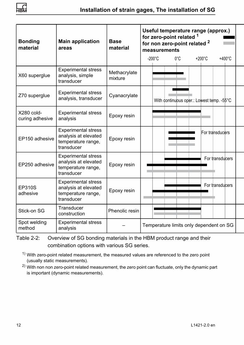
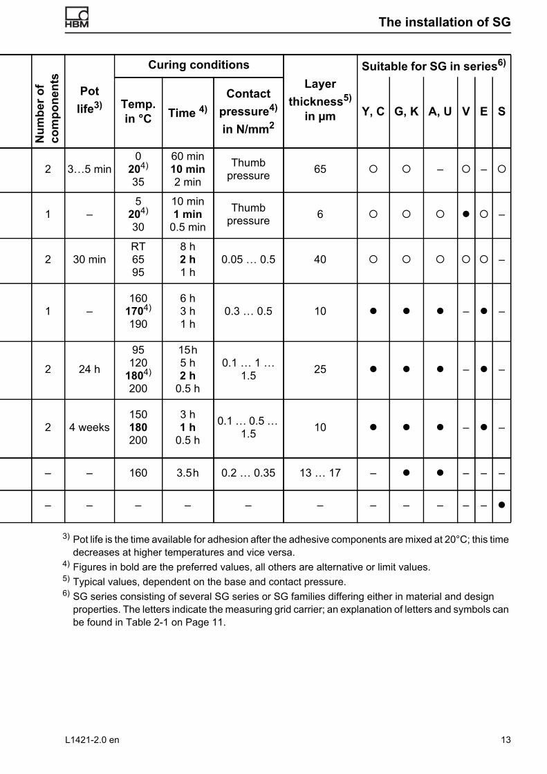
3) Pot life is the time available for adhesion after the adhesive components are mixed at 20°C; this time decreases at higher temperatures and vice versa.
4) Figures in bold are the preferred values, all others are alternative or limit values.5) Typical values, dependent on the base and contact pressure.6) SG series consisting of several SG series or SG families differing either in material and design
properties. The letters indicate the measuring grid carrier; an explanation of letters and symbols can be found in Table 2-1 on Page 11.
com
pone
nts
Pot life3)
Curing conditionsLayer
thickness5) in μm
Suitable for SG in series6)
Temp.in °C Time 4)
Contact pressure4)
in N/mm2Y, C G, K A, U V E S
3…5 min0
204)
35
60 min10 min2 min
Thumb pressure 65 – –
–5
204) 30
10 min1 min
0.5 min
Thumb pressure 6 –
30 minRT6595
8 h2 h1 h
0.05 … 0.5 40 –
–160
1704)
190
6 h3 h1 h
0.3 … 0.5 10 – –
24 h
95120
1804) 200
15 h5 h2 h
0.5 h
0.1 … 1 … 1.5 25 – –
4 weeks150180200
3 h1 h
0.5 h
0.1 … 0.5 … 1.5 10 – –
– 160 3.5 h 0.2 … 0.35 13 … 17 – – – –
– – – – – – – – – –
L1421-2.0 en 13

Installation of strain gages, The installation of SG
2.3 Characteristics of the various HBM SG adhesives
• X60 superglue This pasty adhesive is preferentially used for stress analysis investigations within the natural temperature range (approx. -20 ... +50 °C). It can however also be used for measurements down to -200°C. The pasty consistency makes it suitable for installing SG on porous, absorbent materials. It is popular with installation engineers thanks to the relatively easy processing. The necessity of mixing two components before each gluing process compares positively to the working time available (at room temperature) of approx. 3 minutes; this is long enough to permit complex installations (e.g. where access to the adhesive point is difficult), but short enough to avoid expensive waiting times. The use of X60 for the manufacture of transducers is only restrictedly recommended and should be limited to simple designs with permissible error limits in the percentage range.
• Z70 superglue This low-viscosity cyano-acrylate adhesive, which dries in seconds, permits - and requires! - a rapid working speed that requires good access to the adhesive point. Due to the extremely thin adhesive layer and the higher temperature limits, a lower measurement uncertainty can be achieved than with the X60, especially in the temperature range above 50 °C up to the temperature limit. Z70 is very easy to handle. Due to the low viscosity, Z70 is not suitable for applications on non-absorbent materials. Z70 is suitable for medium accuracy class transducer manufacturing.
• X280 cold-curing adhesive This adhesive is intended for applications where the measurement point is subject to high temperatures but where installation with a hot-curing adhesive is not possible. X280 enables static examinations up to 200 °C and dynamic examinations up to 280 °C. Nevertheless, the adhesive hardens at room temperature within 8 hours. X280 is also suitable for applications on porous materials. It is not recommended for use in transducer construction.
• EP150 adhesiveEP150 adhesive is a hot-curing, one-component, epoxy resin adhesive. It is very viscous, resulting in a thin adhesive layer, economic in use and has a long pot life. The adhesive adheres extremely well to all commercial metals
14 L1421-2.0 en

The installation of SG
and can be used for both static and dynamic measurements in the temperature range between -70 and +150°C. These temperature limits are however fluid and depend on the SG being used, on the expected measurement accuracy and on the curing process. Please note the temperature ranges stated in the SG specifications.EP150 is very suitable for the construction of transducers.
• EP250 adhesive This hot-curing two-component adhesive is suitable for both stress analysis examinations in a wide temperature range and for transducer construction.
• EP310S adhesiveThis hot-curing two-component adhesive is free of fillers, resulting in thin adhesive layers similar to Z70. In comparison to EP250, this results in a lower reaction force of the installation, improved strain transfer from the measurement object to the SG and therefore lower measurement uncertainties. In the stress analysis field, the particular advantages of this adhesive lie in the higher or extremely low temperature ranges that cannot be covered with the above-mentioned adhesives.EP310S is very suitable for the construction of transducers.
• Self-adhesive SG (“Stick-on” SG)The phenol resin based adhesive is hot-curing and already applied to the bottom of the SG. No additional adhesives or activators are required to glue these SG. The adhesive is dry to the touch and therefore facilitates the handling and positioning of SG. Hardening is implemented under pressure at 160°C. These SG are very suitable for the construction of transducers.
2.4 Application of adhesives
Strain gages can be applied to almost all kinds of solid materials. The prerequisite is a suitable and careful preparation of the installation spot. Further details about suitable methods can be found in the operating instructions of the SG adhesives and in the following subsections.
Note 2.4-1:The information below is more detailed than is possible in the instructions for use of the adhesives. However, it is not possible to cover all properties of the various adhesives. If there are any contradictions between the information here and the special data in any instructions for use, then the latter instructions will apply.
L1421-2.0 en 15
Installation of strain gages, The installation of SG
2.4.1 Bonding surface preparation for metals The type and extent of measures for bonding surface preparation depend on the condition of the measurement object, extent and type of contamination and the material being bonded. The following schematic lists the various stages of pre-treating metallic objects. The aim is to create a surface without pores, notches and oxides, not too rough and easily wetted. The individual measurement object preparation stages:• Coarse cleaning
• Smoothing
• Cleaning
• Roughening
• Cleaning
• Marking
• Fine cleaning and degreasing
• Pickling, rinsing and drying if necessary
Which of the steps are necessary and which materials should be used depends mainly on the condition, size and sensitivity (against damage) of the object. The installation technician must decide accordingly from case to case. The respective measures are explained in the following descriptions.
The terms “cleanliness” and “contamination” must be explained first as it is essential that they are clearly understood by the installation technician. Every open surface must be seen in principle as contaminated even if it appears smooth and clean to the eye. Deposits of dust, oxidation, adsorption of moisture, vapors and gases occurs continuously, constantly re-contaminating the surface and reducing bonding capability with adhesives. This is why bonding should be implemented as rapidly as possible after the bonding surface has been cleaned. Pauses between the individual stages of measurement point preparation are not permitted. Even under laboratory conditions and favorable air conditions, an interval of 3 hours between cleaning and installation must be seen as the upper time limit. Bonding must be implemented immediately after cleaning on rapidly oxidizing materials or in industrial atmospheres.
• Coarse cleaningRemove all rust, scale, paint coatings, thick lubricant and dirt layers, and other impurities or surface coatings from a generous area around the
16 L1421-2.0 en
The installation of SG
measuring point. Use scrapers, spatulas, grinding equipment or similar tools; household detergents can also be used for coarse cleaning of lubricant and grease layers. Caustic soda solution is also a good fat solvent for coarse cleaning, but must be used with great care. It has a corrosive effect on the skin, rubber globes and protective glasses must therefore be worn while using it. Caution! Do not use caustic acid on aluminum! Rinse thoroughly with deionized or distilled water afterwards. Sufficient degreasing is evidenced by an unbroken water film running off the surface. Dry the measuring point with a clean cellulose pad.
• Smoothing Rust, scars and deep scratches produce notch strains on the surface of the object and lead to incorrect measurement results. Humps and other uneven features prevent the SG from bonding. You must therefore smooth the bonding point by grinding, filing or other suitable methods. Grinding tools with rubber plates and replaceable emery wheels are most suitable. The rubber plate follows the contours of the object and the emery wheel grain can be selected to match the purpose; start with a coarse grade followed by finer and fine grades. To avoid misunderstandings: The bonding area must not be flat (an SG can also be bonded to curved surfaces), it must simply not be “bumpy”. Coatings with lead, cadmium, tin, indium, bismuth and similar metals bind poorly or not at all with adhesives and must therefore be removed. Nickel coatings may peel and should also be removed.
• Cleaning Dirt, grinding dust and grease should be removed in this step. Cleaning must be thorough but not extreme as further steps will follow. Organic solvents are recommended as cleaning agents. Further details can be found under the keyword “Fine cleaning” below. Mineral oils such as those used during rolling of sheet metals, boring emulsions, cutting oil, etc. are insufficiently removed with general organic solvents. Alkaline agents are more suitable in this case.
• Roughening Section 2.1 and Note 2.1-1 have explained that the bonding forces between the fitting piece and adhesive are mainly chemical in nature. An increase in bonding force is only possible by increasing the contact surfaces. This can only be achieved by roughening. This is usually done mechanically, or in rare cases chemically by pickling.
L1421-2.0 en 17

Installation of strain gages, The installation of SG
Fig. 2-1: Influence of surface roughness on effective contact surface size left: Contact line with ideal-smooth object surface right: Extended contact line through light roughening (optimal condition)
• Roughening with sandblastingAn ideal bonding base is achieved with sandblasting. The requirement for perfect surfaces are oil and water-free compressed air, clean (unused) abrasive medium and totally grease-free surfaces as grease particles that are embedded by the sandblaster are extremely difficult to remove, at the most with an ultrasonic cleaning device. Corundum is recommended as the abrasive agent. It is sharp-edged, hard and clean, does not cause corrosion and is physiologically harmless (no silicosis). For extremely hard materials, (e.g. hard metals), boron carbide is a proven medium, a material with a hardness between diamond and corundum. The appropriate grain depends on the hardness of the material being sandblasted, the air pressure, the distance between the nozzle and object and the system used. Table 2-1 shows empirical values (recommended values).
Component material
Roughening by sandblastingGrinding (Paper or
cloth)Grain size
Air pressure
in bar
Distancein cm
Corundum
Grain No.Average
grain size in μm
Hardened steel 4 20 80 … 100 160 … 115 80 … 220
Mild steel 4 20 100 … 150 115 … 75 100 … 220
Aluminum, Al-cast parts 3 25 F240 … F320 45 … 29 220 … 360
Table 2-1: Recommended values for the grain size of corundum or emery paper/cloth for roughening workpieces before SG installation.
Adhesive
Fitting piece (measurement object)
18 L1421-2.0 en

The installation of SG
When using cyano-acrylate adhesives (e.g. Z70), less roughening (finer grain) is recommended, while stronger roughening with coarser grains is better for pasty bonding media. Table 2-2 provides recommended values for optimal roughening depths (rms).
• Roughening with grinding Despite the obvious advantages of sandblasting, applications are limited either due to lack of appropriate systems or because the measurement object does not permit such treatment, e.g. being located near machine bearings. In such cases, use emery paper. Used correctly, it also delivers satisfactory results. The emery paper should be rubbed in circles across the surface to prevent strength-reducing preferential directions. Always use new emery paper (or emery cloth) and a grain size suitable for the material hardness. Table 2-1 shows the recommended values for grain sizes, while roughness depth values are recommended in Table 2-2.
• Roughening with other mechanical methodsEven grinding may be too coarse a method for roughening the contact surfaces on some objects and is therefore not permitted. This applies mainly to notch-sensitive materials where the surface treatment must be retained. The mildest form of mechanical pretreatment for roughening and removing oxide layers is abrasion with a glass eraser (glass fibre eraser pen). Please note that the abraded material must not be removed using the hand or by blowing it away. Then there are also chemical methods that are described in the section “Pickling”.
• Marking Indicate the exact position of the SG by marking the measurement object. Foil SG have marks to identify the centre axes of the measuring grid. Marking using a scribing iron is not recommended as the damage to the
SG bonding material Average roughening depth in μm
X60 superglue 3 … 10
Z70 superglue 2 … 4
X280 adhesive 2 … 10
EP150, EP250 and EP310S adhesive 2 … 4
Table 2-2: Recommended roughening depth of bonding surfaces on the measurement object for various SG adhesives.
L1421-2.0 en 19

Installation of strain gages, The installation of SG
surface can lead to damage or breakage of the object itself. An (empty) ballpoint pen is far more suitable as the ball leaves a clearly visible line without making any notches. If the pen still contains ink, the ink must be removed after marking with a solvent (e.g. RMS1 or RMS1-Spray). A sharp pencil can be used to mark soft materials, e.g. aluminum. The necessary hardness (between 4H and 6H) should be checked first on a material sample (the lines should still be visible after fine cleaning, but leave no grooves).
• Fine cleaning The efficiency of the bonding forces described in Section 2.1, Page 8 decreases with the third to sixth power of the distance. It is therefore limited to molecular layers. Very careful fine cleaning is therefore essential. Even the thinnest layers of grease will affect or neutralize the effectiveness of the boundary forces in particular. Silicone greases and oils are the most difficult to remove and these are present in numerous cosmetic products (skin cream, etc.). Such products should not be present during SG installation. If equipment is available and the object permits, vapor degreasing is recommended. In normal cases, degreasing is implemented by washing with chemically pure grease solvents (e.g. RMS1 or RMS1-Spray). Note the relevant health and safety regulations! Good ventilation is essential so that formation of ignitable gas-air mixtures is prevented and so that collection of solvent vapors heavier than air does not occur in pits, etc. (danger of suffocation).
Cleaning agentThe organic solvents that are preferentially used for cleaning are usually available in two different purity grades: • “Technically pure” means: free from solid contaminants;
• “Chemically pure”, also indicated by the supplement “pro analysi” or “p. a.” or “very pure”, means: also free of soluble contaminants within technically feasible limits.
SG installation points should always be cleaned with chemically pure solvents. With RMS1 and RMS1-Spray, HBM offers you chemically high purity, environmentally-friendly solvent combinations that remove all general contaminants.
20 L1421-2.0 en
The installation of SG
Other commercial solvents are e.g. acetone, methyl-ethyl-ketone, isopropyl alcohol, ethyl alcohol and ethyl acetate.
Please note the following points when fine cleaning: • Wash hands beforehand and between each step if necessary.
• Do not use skin creams; if necessary, then grease-free skin ointments (see Section 2.4.6, Page 38).
• Never use solvents directly from the supply container. Pour a small amount into a clean vessel (Petri dish) and then use that. Never pour left-over liquid back into the container, discard any excess.
• Use clean, grease and lint-free cleaning pads. Cellulose pads are well-proven. Only use each pad once! Paper tissues can only be used if they do not contain any soluble components (perfumes)!
• Do not immerse fingers in the solvent as this dissolves skin grease which will then contaminate the solvent. Use rubber gloves, rubber fingers or tweezers.
• First, clean a larger area, then clean ever smaller areas, so that dirt and impurities are not rubbed into the bonding point from the edges.
• Continue cleaning until no sign of contamination can be seen on a pad. Then use a new pad each time to wipe once from the centre to the outer areas in at least 2 opposing directions. Use tweezers or clean tissue paper to remove any lint that may still be present, do not blow off!
• If moisture condenses on the bonding area (following cooling due to solvent evaporation), use a hot air gun to dry the area.
• Once surfaces are clean, do not touch them again with your hands.
Note 2.4-2:With light metals (aluminum and titanium alloys), it is possible that oily substances bleed out onto the surface, even after thorough cleaning and degreasing. This “bleeding” is probably due to lubricants rolled into the metal surface. Countermeasure: Clean, heat, clean again, etc. until the bonding area remains clean. However, subsequent loosening of the installation cannot be wholly excluded.
• Pickling Chemical pretreatment of bonding areas by pickling is rarely implemented in SG technology due to the workload. It is nonetheless mentioned here for the sake of completeness.
L1421-2.0 en 21
Installation of strain gages, The installation of SG
Pickling can be used in addition to or instead of mechanical pretreatment. In addition to activating boundary forces, it also produces a very fine roughening. This microscopically fine roughness has the advantage that the stability of the measurement object remains unaffected. A particular advantage is that very thin objects are not bent or buckled. Pickling results in a very good and uniform adhesion bonding strength. Pickling must be implemented directly before adhesion. Special care must be taken in neutralization, rinsing and drying of the bonding areas. Various methods are listed in [4] for different metal materials. While pickling of aluminum alloys leads to a noticeable improvement in bonding strength, compared to other pretreatment methods, this influence cannot be seen for steel [5].
2.4.2 Bonding surface preparation for non-metals• Concrete
Bonding surface preparation of concrete is aimed at the use of X60 superglue and is generally simpler than metal installations. It must be determined whether the concrete was cast with oiled or dry molds. In the former case, the oil-soaked layer must be removed with a grindstone. Degreasing with solvents is not recommended as the solvent and the dissolved oil will only penetrate deeper into the concrete. If dry molds were used, simple remove the concrete laitance until solid concrete is reached. Grinding is also recommended here to obtain as flat a surface as possible. Blow off the grinding dust carefully with an air pump or with oil and water-free compressed air. Seal pores with X60 thoroughly, filling them completely, not just on the surface. Smooth the bonding areas, do not apply a layer. After approx. 30 minutes, a thin aluminum foil can be applied as a barrier layer or, under certain circumstances, the SG can be attached (see Note 2.4-3).
Note 2.4-3:Concrete requires a strong pore-filling adhesive that bonds reliably even if residual moisture is still present. The superglue X60 has proven itself here. The inhomogeneous structure of concrete requires SG with long measuring grids for mean value calculation. For more information refer to [18].Direct bonding of SG to concrete is only recommended for dry parts: if residual moisture is present, it is recommended that a thin aluminum foil is applied first as a barrier layer and the SG on top of the foil. Zero-point related measurements are only possible on concrete if the sample is completely dry or if the moisture content remains constant during the measurement. Concrete shrinks
22 L1421-2.0 en

The installation of SG
or swells if the moisture content changes. This is why zero-point related measurements are usually only possible over relatively short periods of time, unless an equivalent, unloaded object is available for compensation. The rules for metal installation apply to installations on reinforced concrete.
Note 2.4-4:When measuring concrete, you should consider the use of mounted strain transducers, e.g. the SLB700A.
• Glass (silicate glass), glazed porcelain, enamel The degreased glass surfaces can be bonded directly with the adhesives X60, Z70 and EP250. Roughening or other preparations are not necessary. X60 can be removed by dissolving it with methyl-ethyl-ketone or acetone, Z70 can be removed by soaking in slightly alkaline (detergent) warm water. EP250 can be scratched off polished glass. SG can be installed in the same way on glazed or enameled materials, and on ground surfaces of stoneware articles, etc. [6].
• Plastics Plastics can be divided roughly into two groups for which different pretreatment methods must be used: a) Soluble plastics that are easy to bondb) Difficult or insoluble (usually non-polar) plastics that cannot be bonded or
only with great difficulty without pretreatment.
Group a) mainly comprises the amorphous structure plastics (e.g. polystyrene [PS] and PS modifications, polyvinyl-chloride [PVC], polycarbonate [PC], cellulose-acetobutyrate [CAB], polymethyl-methacrylate [PMMA]).
Group b) includes the partially-crystalline plastics (e.g. high density polyethylene [HDPE], low density polyethylene [LDPE], polypropylene [PP], polyoxymethylene [POM] (polyacetal), polyamide [PA]).
The physical or chemical pre-treatments used on plastics are intended to activate the molecular structure of the surface. Pre-treatment of soluble plastics involves the removal of processing additives, particularly release agents (silicone, talcum), lubricants (stearates), surface contamination and “mold skins” (on molded or injection molded parts). Organic solvents, organic sulfonates or alkaline phosphates can be used for degreasing. Roughening with fine emery paper (grain 220 to 360) is also a suitable measure. The above-mentioned methods may sometimes provide
L1421-2.0 en 23

Installation of strain gages, The installation of SG
sufficient bonding capability in difficult or insoluble plastics, but in most cases more rigorous treatment is required to modify the plastic structure surface and achieve bonding capability. More detailed information about the pre-treatment of plastics can be found in [7], [8]. Care must be taken when handling plastics with solvents as they can cause swelling and/or stress corrosion. Pure benzene (not on polystyrene) and isopropyl-alcohol are considered to be safe, particularly with regards to the short contact time. In critical cases, a test should always be carried out first as it is not possible to predict results due to the large number of modified plastics in use. In this regard, the work in [9] must be referred to as it reports comprehensively on the installation of SG on plastics and the related problems. Modern processes, particularly for pre-treatment, also include corona or plasma treatment with significantly improves bonding force.
Note 2.4-5:List of successful installations of various types of plastics after simple methods of pre-treatments. 1) HD polyethylene (HDPE) structural foam: Bonding with Z70 superglue.
Preparation: Bonding area roughened with dry, clean emery paper grain 320 worked in circles, dust carefully removed. Bonding strength sufficient for < 20,000 μm/m.
2) Polypropylene(PP): Bonding with X60 superglue and Z70 superglue. Preparation: as for 1). Strain level achieved: = 50,000 – 60,000 μm/m.
3) Polyoxmethylene (POM), polyacetal. Bonding with Z70 superglue. Preparation: Dry roughening with emery paper grain 220. Very good bonding strength.
4) Phenolic resins, cresolic resins, melamine resins and laminates thereof. Bonding with X60 superglue. Preparation: Dry roughening with emery paper grain 220.
5) Polymethyl-methacrylate (PMMA), acrylic glass. Bonding with X60 or Z70 superglue. Preparation: Degrease only. Very good bonding strength.
6) Polyvinyl-chloride (PVC), without softeners. Bonding with X60 or Z70 superglue. Preparation: Degrease only. Very good bonding strength.
7) Polycarbonate (PS). Bonding with X60 or Z70 superglue. Preparation: Dry roughening with emery paper grain 220 to 320. Good bonding strength.
8) Polyester resins (fully cured, also fiberglass or carbon fiber reinforced). Bonding with X60 or Z70 superglue. Preparation: as for 7). Good bonding strength.
9) Epoxy resins (EP). Bonding with X60 or Z70 superglue. Preparation: as for 7). Very good bonding strength.
10) Polystyrene (PS). Bonding with Z70 superglue. Preparation: as for 7). Very good bonding strength.
Note 2.4-6:Some methods for pre-treatment of polyolefines, see also [2], [4], [7], [8].
24 L1421-2.0 en

The installation of SG
1) Low density polyethylenes (LDPE) - alternative methods. a) “Iron-on” phenolic resin SG with heated tool. b) Melt a fine surface layer on PE with a gas flame. Makes the PE bondable. c) Corona or plasma treatment possible.
2) Polyamides (and other plastics) become bondable if treated with hydrogen peroxide [2].
• WoodWood can be bonded with the X60 superglue after being dry grinded with glass or flint paper.
Note 2.4-7:Wood is an inhomogeneous, anisotropic and porous material. These properties, which dominate in conifer wood used for building, make SG measurements problematic. In addition to the extreme differences in the elasticity characteristics due to the structure of wood, changes in these values due to penetration of the adhesive into surface layers must be taken into account. Promising measurement results can be obtained where measuring points can be calibrated and a sufficiently long SG measuring grid is used to average the partial strains (as with concrete).
• Rubber After degreasing with a solvent named in Section Cleaning agent, Page 20, rubber can be bonded with Z70 or X60 superglues. Light roughening with emery paper may be necessary in some cases.
Note 2.4-8:Strain measurements on rubber may be problematic because the strain suppression resulting from the reaction force (resistance to expansion) increases the softer the rubber is. In addition, it cannot be assumed, due to the high elongation properties of certain SG types, that they are suitable for measuring great strains on rubber because this high elongation is only available once (or at the most, a couple of times). Low reaction strain transducers are more suitable for such applications. See also [10].
2.4.3 Use of SG in medical technology SG technology has mainly found use in medical research in the sectors of surgery, orthopedics and dentistry. If SG are to be used in conjunction with metallic or non-metallic instrument, e.g. for measurements on osteosynthesis plates, prostheses, etc ., the same installation techniques can be used as in the technical sector. Toxic or allergic reactions caused by contact with the installation media must be excluded if SG are used on or in living organisms. Tissue-compatible materials must be selected for implants, materials that must be resistant against digestive enzymes if in place for longer periods of time.
L1421-2.0 en 25

Installation of strain gages, The installation of SG
Information available to the author indicates that the following materials have been used successfully in in-vivo installations: • For degreasing: Ether
• For bonding: Histoacryl® blue (manufacturer: B. Braun Melsungen AG)
• SG: Series “Y” (polyimide measuring grid carrier)
• For wiring: Leads insulated with polytetrafluorethylene (PTFE, Teflon®) or low density polyethylene (LDPE)
• For protective covering: ABM75 covering tape or the viscous mass itself used in ABM75, covered with PTFE foil
Detailed description of installation techniques for bones can be found in [11]. For further SG applications in the medical sector, refer to [12] to [15].
The Z70 superglue can be used for installations on dead organisms with silicone rubber SG 250 as the protective cover. As the physiological properties of these two materials are not known, their application in vivo is not recommended.
Installations on soft tissues are not promising due to the reaction force (resistance to expansion), unless investigations are limited to the purely qualitative display of processes, e.g. muscle reflexes.
2.4.4 SG preparation • Cleaning
HBM strain gages are delivered ready for use and do not require any special treatment. However, if the adhesive side of the SG is touched with fingers or contaminated in any other way, clean it with a cotton bud soaked in solvent (RMS1).
• Adaptation to the workpiece contours The flexibility of SG mainly depends on the properties of the measuring grid carrier and, to a small extent, also on other components, e.g. integral solder terminals. Table 2-3 lists the smallest curvature radii with which the SG can be installed without requiring special treatment for the various SG series. The polyimide carriers in the Y series strain gages are so flexible that they can be bonded onto sharp edges without being damaged. Other carriers are more brittle and will break if they are bent too sharply. However, they can be easily prepared for installation on smaller radii by “pre-forming” them. This is most easily done using a soldering station with controlled temperature,
26 L1421-2.0 en
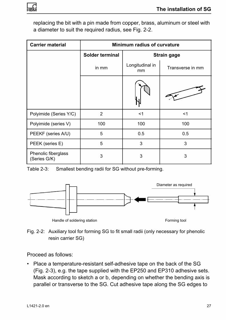
The installation of SG
replacing the bit with a pin made from copper, brass, aluminum or steel with a diameter to suit the required radius, see Fig. 2-2.
Fig. 2-2: Auxiliary tool for forming SG to fit small radii (only necessary for phenolic resin carrier SG)
Proceed as follows:
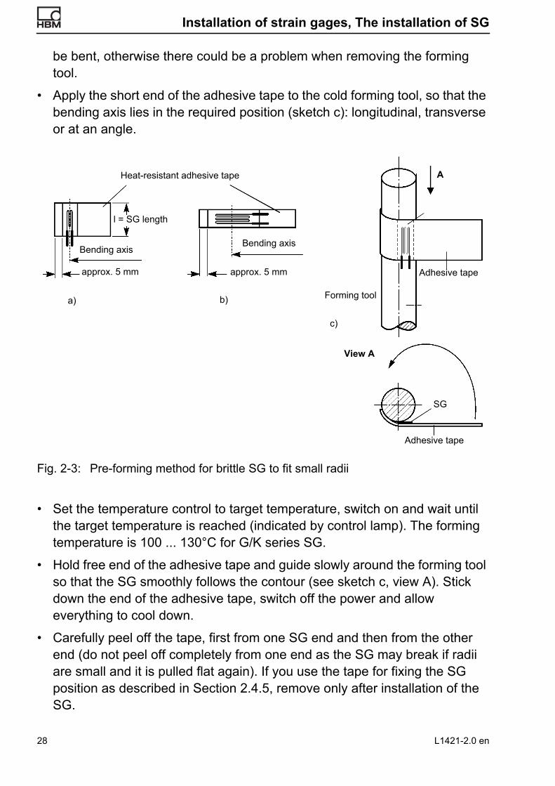
• Place a temperature-resistant self-adhesive tape on the back of the SG (Fig. 2-3), e.g. the tape supplied with the EP250 and EP310 adhesive sets. Mask according to sketch a or b, depending on whether the bending axis is parallel or transverse to the SG. Cut adhesive tape along the SG edges to
Carrier material Minimum radius of curvature
Solder terminal Strain gage
in mm Longitudinal in mm Transverse in mm
Polyimide (Series Y/C) 2 <1 <1
Polyimide (series V) 100 100 100
PEEKF (series A/U) 5 0.5 0.5
PEEK (series E) 5 3 3
Phenolic fiberglass (Series G/K) 3 3 3
Table 2-3: Smallest bending radii for SG without pre-forming.
Diameter as required
Handle of soldering station Forming tool
L1421-2.0 en 27
Installation of strain gages, The installation of SG
be bent, otherwise there could be a problem when removing the forming tool.
• Apply the short end of the adhesive tape to the cold forming tool, so that the bending axis lies in the required position (sketch c): longitudinal, transverse or at an angle.
Fig. 2-3: Pre-forming method for brittle SG to fit small radii
• Set the temperature control to target temperature, switch on and wait until the target temperature is reached (indicated by control lamp). The forming temperature is 100 ... 130°C for G/K series SG.
• Hold free end of the adhesive tape and guide slowly around the forming tool so that the SG smoothly follows the contour (see sketch c, view A). Stick down the end of the adhesive tape, switch off the power and allow everything to cool down.
• Carefully peel off the tape, first from one SG end and then from the other end (do not peel off completely from one end as the SG may break if radii are small and it is pulled flat again). If you use the tape for fixing the SG position as described in Section 2.4.5, remove only after installation of the SG.
Heat-resistant adhesive tape
Bending axisBending axis
l = SG length
approx. 5 mm approx. 5 mm
SG
View A
A
Forming tool
Adhesive tape
Adhesive tape
a) b)
c)
28 L1421-2.0 en
The installation of SG
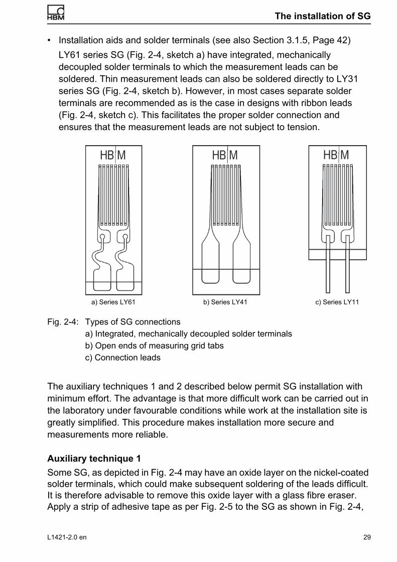
• Installation aids and solder terminals (see also Section 3.1.5, Page 42) LY61 series SG (Fig. 2-4, sketch a) have integrated, mechanically decoupled solder terminals to which the measurement leads can be soldered. Thin measurement leads can also be soldered directly to LY31 series SG (Fig. 2-4, sketch b). However, in most cases separate solder terminals are recommended as is the case in designs with ribbon leads (Fig. 2-4, sketch c). This facilitates the proper solder connection and ensures that the measurement leads are not subject to tension.
Fig. 2-4: Types of SG connections a) Integrated, mechanically decoupled solder terminals b) Open ends of measuring grid tabs c) Connection leads
The auxiliary techniques 1 and 2 described below permit SG installation with minimum effort. The advantage is that more difficult work can be carried out in the laboratory under favourable conditions while work at the installation site is greatly simplified. This procedure makes installation more secure and measurements more reliable.
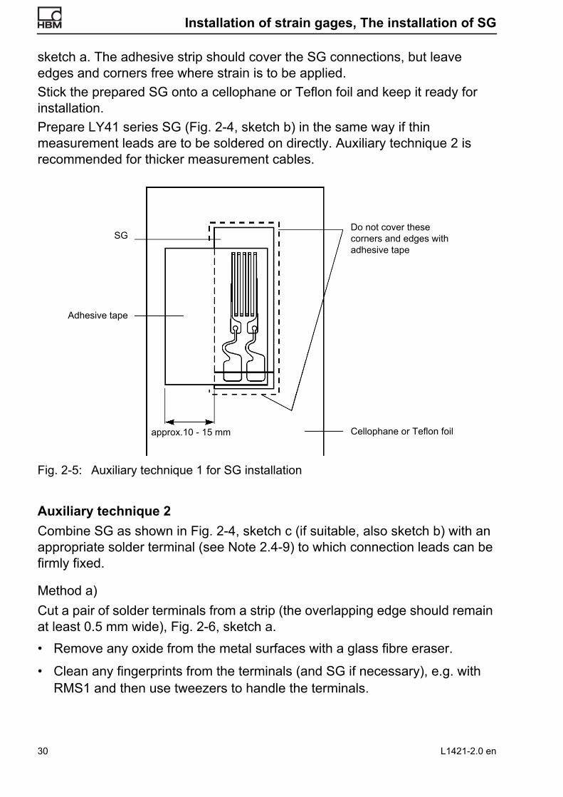
Auxiliary technique 1 Some SG, as depicted in Fig. 2-4 may have an oxide layer on the nickel-coated solder terminals, which could make subsequent soldering of the leads difficult. It is therefore advisable to remove this oxide layer with a glass fibre eraser. Apply a strip of adhesive tape as per Fig. 2-5 to the SG as shown in Fig. 2-4,
a) Series LY61 b) Series LY41 c) Series LY11
L1421-2.0 en 29
Installation of strain gages, The installation of SG
sketch a. The adhesive strip should cover the SG connections, but leave edges and corners free where strain is to be applied. Stick the prepared SG onto a cellophane or Teflon foil and keep it ready for installation. Prepare LY41 series SG (Fig. 2-4, sketch b) in the same way if thin measurement leads are to be soldered on directly. Auxiliary technique 2 is recommended for thicker measurement cables.
Fig. 2-5: Auxiliary technique 1 for SG installation
Auxiliary technique 2 Combine SG as shown in Fig. 2-4, sketch c (if suitable, also sketch b) with an appropriate solder terminal (see Note 2.4-9) to which connection leads can be firmly fixed.
Method a)Cut a pair of solder terminals from a strip (the overlapping edge should remain at least 0.5 mm wide), Fig. 2-6, sketch a. • Remove any oxide from the metal surfaces with a glass fibre eraser.
• Clean any fingerprints from the terminals (and SG if necessary), e.g. with RMS1 and then use tweezers to handle the terminals.
SG
Adhesive tape
Do not cover these corners and edges with adhesive tape
Cellophane or Teflon foilapprox.10 - 15 mm
30 L1421-2.0 en

The installation of SG
Fig. 2-6: Auxiliary technique 2 for SG installation a) Cut off a pair of solder terminals b) Prepare an auxiliary plate and fix the SG with adhesive tape c) Position the solder terminals and cut leads to size d) Fix the solder terminals with adhesive tape
Note 2.4-9:Solder terminals are available in various sizes and designs: Technical details can be found in the brochures. The criteria for selection are:1) Spacing of SG connections2) Space available on the measurement object3) Thermal stability and mounting method
The temperature range of stick-on solder terminals is usually determined or limited by the adhesive used.
Thickness scale, magnified
Leave approx. 1 mm wide edges free from adhesive tape
Separating foil
Adhesive strip
Auxiliary plate
Adhesive strip
Adhesive strip
Lead
Solder terminal
Basis foil of the measuring grid carrierCovering foil of the measuring grid carrier
Adhesive tape for fixing the solder terminal (should not overlap sides)
0.5 … 1 mm
0.5 mm
a) b)
c)
d)
L1421-2.0 en 31
Installation of strain gages, The installation of SG
Method b)
• To facilitate the next step, use a clean support plate made of sheet metal or plastic (approx. 10 cm x 10 cm), cover with cellophane or Teflon separating foil (approx. 3 cm x 6 cm) and tape the edge to prevent slipping. Carry out the next steps on this support.
• Stick tape onto the top of the SG, overlapping the SG by approx. 10 -15 mm over one side. The other three sides of the SG must remain free! See Fig. 2-6, sketch. Stick the SG onto the separating foil with the overlapping section of the tape.
Method c)
• Insert the solder terminals between the basis foil of the measuring grid carrier and connections, see Fig. 2-6, sketch c, and then shorten the connection leads.
Method d)
• Join the SG and solder terminal with tape; cover the entire metal surface with tape, see Fig. 2-6, sketch d. Remove the prepared SG and separating foil from the auxiliary support and keep ready for installation.
Note 2.4-10:If hot curing adhesive is used, the adhesive tape must also be heat-resistant. Such tape is supplied with the appropriate HBM adhesive sets.
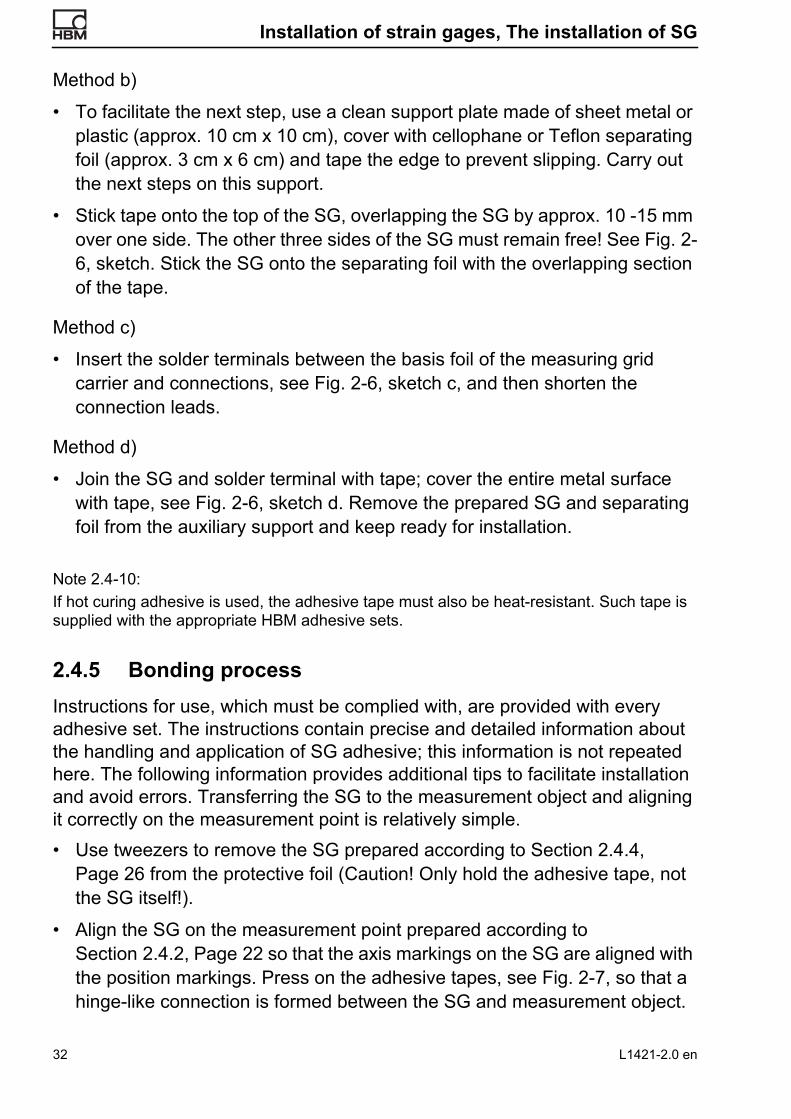
2.4.5 Bonding process Instructions for use, which must be complied with, are provided with every adhesive set. The instructions contain precise and detailed information about the handling and application of SG adhesive; this information is not repeated here. The following information provides additional tips to facilitate installation and avoid errors. Transferring the SG to the measurement object and aligning it correctly on the measurement point is relatively simple.• Use tweezers to remove the SG prepared according to Section 2.4.4,
Page 26 from the protective foil (Caution! Only hold the adhesive tape, not the SG itself!).
• Align the SG on the measurement point prepared according to Section 2.4.2, Page 22 so that the axis markings on the SG are aligned with the position markings. Press on the adhesive tapes, see Fig. 2-7, so that a hinge-like connection is formed between the SG and measurement object.
32 L1421-2.0 en
The installation of SG
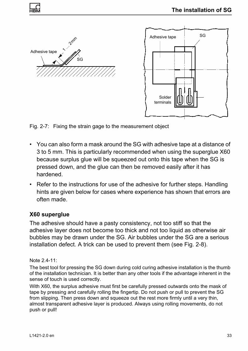
Fig. 2-7: Fixing the strain gage to the measurement object
• You can also form a mask around the SG with adhesive tape at a distance of 3 to 5 mm. This is particularly recommended when using the superglue X60 because surplus glue will be squeezed out onto this tape when the SG is pressed down, and the glue can then be removed easily after it has hardened.
• Refer to the instructions for use of the adhesive for further steps. Handling hints are given below for cases where experience has shown that errors are often made.
X60 superglueThe adhesive should have a pasty consistency, not too stiff so that the adhesive layer does not become too thick and not too liquid as otherwise air bubbles may be drawn under the SG. Air bubbles under the SG are a serious installation defect. A trick can be used to prevent them (see Fig. 2-8).
Note 2.4-11:The best tool for pressing the SG down during cold curing adhesive installation is the thumb of the installation technician. It is better than any other tools if the advantage inherent in the sense of touch is used correctly. With X60, the surplus adhesive must first be carefully pressed outwards onto the mask of tape by pressing and carefully rolling the fingertip. Do not push or pull to prevent the SG from slipping. Then press down and squeeze out the rest more firmly until a very thin, almost transparent adhesive layer is produced. Always using rolling movements, do not push or pull!
Adhesive tape SG
1 … 2
mm
Adhesive tape
Solder terminals
SG
L1421-2.0 en 33

Installation of strain gages, The installation of SG
The adhesive below the SG ensures that the separating foil clings firmly preventing air bubbles from entering. There is then no need to keep pressing the SG down while the adhesive hardens. If air bubbles do form, then the adhesive was too liquid. The separating foil can be removed after several minutes (depending on the temperature). Remove the mask with the surplus adhesive immediately as it is easier to do before the adhesive is fully hardened. Also remove the auxiliary adhesive tape from the SG by carefully and slowly peeling it off with tweezers.
Fig. 2-8: Installing strain gages with X60 superglue a) Fold up the SG, apply adhesive liberally with spatula b) Fold down the SG and press down lightly c) Paste adhesive onto the SG and cover with separating foil d) Press out the surplus adhesive. See Note 2.4-11.
Z70 superglueThis adhesive hardens with seconds if applied very thinly, isolated from the air with a separating Teflon foil, and pressed down with moderate pressure. Application is quite simple and quick:1. Lift up SG 2. Place 1 drop of adhesive on the component and immediately spread out
thinly and evenly with the Teflon strip provided in the set (do not press down)
3. Fold down the SG, immediately apply the separating Teflon foil and press down evenly for approx. 1 minute. See Note 2.4-12. If working upside down, the drop of adhesive can be placed on the Teflon strip and spread onto the installation point.
4. Carefully peel off the auxiliary adhesive tape with tweezers.
SG
X60
Mask made of adhesive
Separating foil
a)
b)
c) d)X60 surplus
34 L1421-2.0 en

The installation of SG
Note 2.4-12:Any interruption in the curing process of Z70 adhesive is damaging. It is absolutely essential that the SG is immediately and evenly pressed down across the entire area. Pressure must remain uninterrupted until the adhesive is fully cured. A frequently observed error is when the SG is only pressed down at points with a finger, i.e. the finger tip is wandering over the SG. This makes it likely that the adhesive only partially cures when pressed so briefly and no longer bonds correctly when pressed again. A pressure pad covered with soft rubber is useful for larger SG where the thumb cannot provide complete pressure. The pad must be adapted to the workpiece contours where necessary. Another error is working too slowly as the adhesive will be completely or partly cured before the SG is pressed down and will no longer bond. This must be taken into account in hot weather in particular. The chemical state of the surface to be bonded can also influence the hardening of the adhesive: Materials with basic reaction speed up hardening, materials with acid reaction slow down or even prevent hardening. The latter case is a rare exception; in most cases, insufficient hardening is due to the adhesive layer being too thick. If an acid reaction is the cause, curing can be forced by using the catalyzer BCY01. In this case, coat the “acid” side thinly with the neutralizer and allow to dry; apply the adhesive to the SG and then press down. Shock curing will then take place within several seconds. This results in residual stresses in the adhesive layer which could affect the extensibility or stability of the bond over a long period of time. The use of this catalyst should therefore be limited to special cases; it is not recommended for routine applications.
X280 adhesiveThe two components of the adhesive are packed in a bag and kept separate from each other with a plastic clip. This ensures the optimal mixing ratio of the components, weighing before use is not required.After the plastic clip has been removed, both components can be mixed together. The adhesive should not be warmed too much by the warmth of the hands as this will reduce the pot life. The adhesive can be mixed by pulling the bag, once the plastic clip is removed, several times over the edge of a table. The pot life is approx. 30 minutes at room temperature. The adhesive is thoroughly mixed when it has a uniform color without any streaks, etc. Please note however that the layer thickness of the adhesive should not exceed 12 mm in depth if being mixed in a pot as otherwise an exothermic reaction will occur, i.e. the adhesive will heat up and cure.The adhesive can also be mixed with the assistance of a very precise scale to obtain smaller amounts than the prepared quantity. 100 parts of component A must be mixed with 52 parts of component B in a container for this purpose.The adhesive must be liberally applied to the SG and workpiece. Use one of the provided wooden sticks or a spatula. The SG can then be pressed on lightly.Cover the installation point with a piece of the provided Teflon tape and then place a piece of the neoprene rubber that has also been provided on top of the
L1421-2.0 en 35

Installation of strain gages, The installation of SG
tape. The Teflon tape should be slightly larger than the rubber to prevent the rubber from sticking to the workpiece.Place a metal plate on the installation point and apply a pressure of at least 0.05 N/mm2. Weights, spring pressure, magnets or similar can be used to apply this pressure.The X280 curing time is eight hours at room temperature. Heating can reduce the curing time, see Table 2-2 on Page 12f.The adhesive does not cure at temperatures below 10°C, curing time is 36 hours at 10°C. If unsure, apply a small spot of the adhesive next to the installation point so that you can check the curing process.
EP150, EP250 and EP310S adhesivesThese adhesives require high temperatures and pressure must be applied during curing. The contact pressure should be 0.1 to 0.5 N/mm2 for stress analysis measurements, higher contact pressures can be used for precision measurements and transducer construction, or when the measurement point is subject to high hydrostatic pressure. Spring-loaded clamps are suitable for generating the contact pressure as they can be adapted to the object and are easy to produce with simple equipment: Fig. 2-9a shows various examples.To protect the SG against pointlike loading, insert a cushion between the thrust piece and SG. The cheapest and best material has been proven to be a cushion, approx. 2 mm thick, made of soft blotting paper. The advantage compared to rubber is that the cushion is flexible in the pressure direction and compensates differences in thickness without protruding sideways and distorting the SG.
Fig. 2-9a: Examples of spring-loaded clamps for SG installation with hot curing adhesives
36 L1421-2.0 en

The installation of SG
Fig. 2-9b: Examples of spring-loaded clamps for SG installation with hot curing adhesives
The springs are necessary both to generate a defined contact pressure and to maintain this pressure when the cushioning material covering the SG gives way under the influence of the heat.
Note 2.4-13:Example for determining the contact pressure.The spring has a spring constant of c = 100 N/mm.The spring constant c, also known as spring stiffness or spring rate, is the force F required to compress the spring with a spring displacement s = 1 mm.
c Fs---=
It can be determined by applying weights to light springs, or in a testing machine for heavier springs. A weight with mass of 1 kg generates a weight force of approx. 10 N (Newton). In this example, the spring used is compressed by 1 mm by a weight of 10 kg exerting a weight force of 100 N. The area to be compressed is 3 cm x 5 cm = 15 cm2. This is the total area of the cushion being compressed, not just the SG itself! The required contact pressure is 5 bar = 50 N/cm2. The clamping screw has a pitch of s = 1.5 mm/revolution. The required force F is then
F 15cm2 5bar 15cm2 50 Ncm2---------- 750N= = =
With a screw pitch s = 1.5 mm and a spring constant c = 100 N/mm, the force increase F per screw revolution is:
F srev .----------- c 1.5 mm
rev .----------- 100 N
mm---------- 150N rev . = = =
The required force F = 750 N is achieved with:FF------- 750N
150N rev . ---------------------------------- 5 spindle revolutions= =
L1421-2.0 en 37

Installation of strain gages, The installation of SG
2.4.6 Precautionary measures The following hints are not intended to cause unnecessary fear; there is no justifiable reason for this based on numerous years of experience. However, they are intended to warn against excessive carelessness and the consequences. A filter mask must be used when roughening beryllium and its alloys. Beryllium, in particular beryllium dust, is carcinogenic (can cause cancer).When bonding SG, ensure that everything is extremely clean. This applies not only to bonding points and SGs, it also applies to the same extent for hands. Sensitive persons can have an allergic reaction when handling solvents and chemically cured adhesives, which generally include most SG adhesives. Avoid direct contact with skin where possible. Always wash hands thoroughly with tepid water and neutral soap when bonding is complete or at intervals when installations take longer. A further hint is required in the case of Z70. Z70, a cyanoacrylate adhesive, is supplied in small plastic phials with sealed plastic nozzles. During transport the nozzle tip usually fills with adhesive. This adhesive may squirt out when the tip of the nozzle is cut off. When opening the phial, hold it so that the adhesive cannot squirt onto the face or clothes of anyone in the vicinity. If a drop of Z70 gets into the eye, it will cure immediately due to the tear liquid. This polymerization reaction will produce heat that will slightly irritate the cornea of the eye. A brief, but sharp pain will be felt during the first few minutes. Rinse the eye immediately with tepid water! An optician should be consulted as a precaution. Previous experience has shown that the cornea regenerates within a few days, there is no permanent sight damage. Z70 cannot be removed from clothing. The use of skin creams must be mentioned here. Many creams contain silicone grease. This spreads over any items (tools) that it comes into contact with and is then transported further, even onto measurement points. It is hardly visible and very difficult to remove. Even molecular layers can cause reduced adhesive adhesion. The use of such creams is therefore not recommended.Ensure good ventilation is available when installing SG as the vapors of the solvents and adhesive should not be inhaled. Comply with the safety data sheets and applicable rules for the prevention of accidents.
38 L1421-2.0 en

Connecting the cables
3 Connecting the cables
The best and most common method of electrical connection between the SG and the measuring lead (cable) is soldering. The following chapters look at this method in detail. Excellent connections can also be obtained with crimping (squeezed connections). Clamp connections can cause zero point shifts due to contact resistance fluctuations. Plug connections are even more critical; only top quality plugs with gold-plated contact elements have been proven to be sufficient, and only then when perfect function is not hindered by contamination. In principle, it can be said that normal high current connections are insufficient because of the low measurement voltages and currents concerned.
3.1 Soldering tools, soldering materials, connection materials
3.1.1 Soldering irons Temperature-controlled low voltage soldering irons are recommended. Use models with sensitive, continuous electronic control and high heating power (approx. 50 W or approx. 80 W for lead-free solders), as the heat lost at the soldering tip is immediately replaced during soldering. The temperature control range of commercial soldering stations lies between 120 and 400°C, sufficient for all soft solders used in SG technology.
3.1.2 Soldering tips The selection of the right soldering tip for the application case is decisive for the production of reliable solder joints. The designation “soldering tip” should not be taken too literally as a pencil-shaped soldering tip is unsuitable (Fig. 3-1a) because the heat flow from the tip to the solder joint is insufficient and because the solder is pulled up away from the tip and is therefore missing at the solder joint. A small area, suitable in size for the solder joint, is recommended, Fig. 3-1 b, c and d. The accessibility of the solder joint determines the use of a straight or curved solder tip. Coated solder tips only take up solder at specific points so that the solder is concentrated at the actual soldering joint. This coating also protects the tip against oxidation.
L1421-2.0 en 39

Installation of strain gages, Connecting the cables
Fig. 3-1: Various soldering tip shapes
3.1.3 Solders (soft solders) Numerous types of soft solder are available. They optimally meet various requirements dependent on the alloy components and compositions. Good wetting and flow properties, as well as melt temperatures suitable to application conditions, are essential for SG installations.The maximum operating temperature, taking into account the mechanical strength of the solder connection, should lie at least 30 K below the solder melting point.
Note 3.1-1:It is occasionally noted that tin solders undergo a phase transformation at low temperatures, decomposing from normal white tin (-phase) into grey, powdery tin (-phase). This phenomenon, called “tin pest”, only occurs in high purity tin and then only under unfavorable conditions. Normal tin solders with alloy components or residual contamination with lead, antimony, bismuth, copper, arsenic, iron, etc. do not evidence deterioration, even after storage for 10 years at -40°C. This is reported in detail in [16].
Small amounts of copper prevent annoying corrosion of soldering tips (“copper protective solder”). Solders with high fatigue resistance are an advantage for dynamic continuous loading.Some common soft solders are listed in Table 3-1. Further information can be found in DIN EN 61 190-1/1-3 and the solder manufacturer lists.
a) unsuitable, too sharp
b) single-sided surface
c) double-sided surface
d) curved form
Size of surface area matched to soldering object}
a) b) c) d)
40 L1421-2.0 en
Connecting the cables
Note 3.1-2:Welded connections should be implemented in the high temperature range. Hard solders should only be used with caution due to the aggressive fluxes!
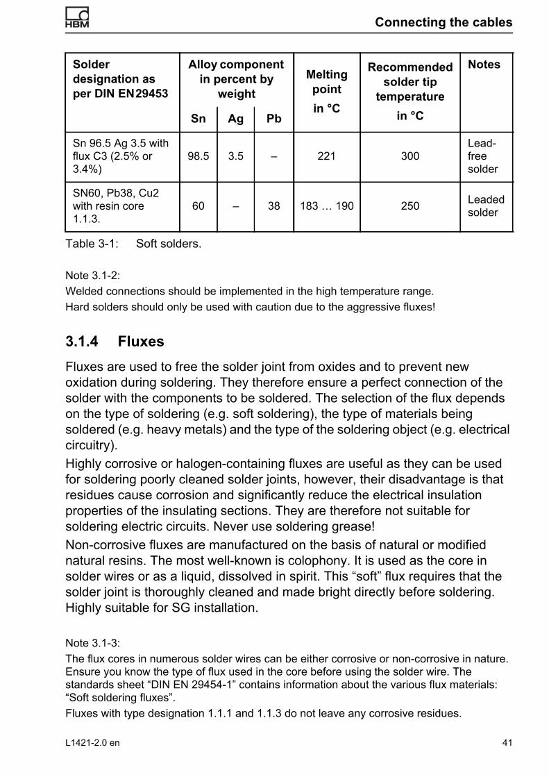
3.1.4 Fluxes Fluxes are used to free the solder joint from oxides and to prevent new oxidation during soldering. They therefore ensure a perfect connection of the solder with the components to be soldered. The selection of the flux depends on the type of soldering (e.g. soft soldering), the type of materials being soldered (e.g. heavy metals) and the type of the soldering object (e.g. electrical circuitry). Highly corrosive or halogen-containing fluxes are useful as they can be used for soldering poorly cleaned solder joints, however, their disadvantage is that residues cause corrosion and significantly reduce the electrical insulation properties of the insulating sections. They are therefore not suitable for soldering electric circuits. Never use soldering grease!Non-corrosive fluxes are manufactured on the basis of natural or modified natural resins. The most well-known is colophony. It is used as the core in solder wires or as a liquid, dissolved in spirit. This “soft” flux requires that the solder joint is thoroughly cleaned and made bright directly before soldering. Highly suitable for SG installation.
Note 3.1-3:The flux cores in numerous solder wires can be either corrosive or non-corrosive in nature. Ensure you know the type of flux used in the core before using the solder wire. The standards sheet “DIN EN 29454-1” contains information about the various flux materials: “Soft soldering fluxes”.Fluxes with type designation 1.1.1 and 1.1.3 do not leave any corrosive residues.
Solder designation as per DIN EN 29453
Alloy component in percent by
weightMelting pointin °C
Recommended solder tip
temperaturein °C
Notes
Sn Ag Pb
Sn 96.5 Ag 3.5 with flux C3 (2.5% or 3.4%)
98.5 3.5 – 221 300Lead-free solder
SN60, Pb38, Cu2 with resin core 1.1.3.
60 – 38 183 … 190 250 Leaded solder
Table 3-1: Soft solders.
L1421-2.0 en 41
Installation of strain gages, Connecting the cables
3.1.5 Solder terminalsThe task of solder terminals and their applications have already been mentioned in Section 2.4.4, Page 26. Solder terminals are produced in various designs and sizes, including ones that are fixed with spot welding. (Fig. 3-2 shows some typical forms of solder terminals; the actual range can be found in the latest, applicable brochures.) Usual designs consist of polyimide foil to which the nickel-plated copper surface is fixed with a heat-resistant adhesive. Thermal stability is 180°C for continuous applications and 260°C for short-term operation.Select the size of the solder terminals according to the size of the SG and the thickness of the cable wired to be soldered. Smaller solder terminals are better for high dynamic loading, alternatively, you can install the solder terminals transverse to the strain direction. You can also cut the solder terminals through the middle and then align the cut edge to the SG so that short circuiting is prevented. Bonding is implemented directly with the SG (as described in Section 2.4.4, Page 26) and using the same adhesive used for the SG.
Fig. 3-2: Some solder terminal forms (examples)
3.1.6 Lead materialThe success of a measurement also depends on selecting the correct, i.e. suitable connection leads and measurement cables. They should not only transmit the measurement signals between the measurement chain elements (transducer - amplifier), but also limit noise signals to an acceptable minimum and withstand the operating and ambient stresses.Short connections, e.g. internal wiring inside a transducer, can be implemented with jumper wires or stranded wires with relative thin cross-sections. Wire insulation must be high and suitable for the expected temperatures. Good solderability of the wires is also necessary. So-called “very flexible stranded wire” can be advantageous if the measurement object is subject to extreme dynamic stress. The core consists of numerous very thin strands surrounded
LS7
LS5
LS4
LS2
42 L1421-2.0 en

Connecting the cables
by flexible insulation. Ensure that wiring within the bridge is “symmetrical”, i. e., that identical wires with the same length are used.Additional requirements must be met for longer connections and cables. The correct selection of the cable cross-section is important to keep the ohmic resistance within acceptable limits. Low-capacitance cable is recommended for carrier frequency operation, and for DC operation if higher frequency signals are to be transmitted. A copper mesh sheathing the cores helps to make core capacitances symmetrical to each other and also protects against disturbing stray effects from electric fields (electric shielding). Lay the cables in steel tubes, or similar, for protection against magnetic fields.
Note 3.1-4:Electrostatic influences occur if capacitive coupling of a voltage source electrical field acts on the measurement circuit. The best protection is to sheath the cable or lead with a closed shield. A copper mesh is usually sufficient protection. Special measurement cables contain such a shield. It is important to earth the shield as a shield on a free potential has no effect.Electromagnetic influences occur when measuring circuit cables are laid in the vicinity of conductors carrying a current or electrical equipment (e.g. generators, welding equipment, transformers, motors, etc.). Disturbing electrical voltages are induced in the measuring leads based on the transformer principle. An effective protection is to twist the cores (the cores are twisted in prefabricated measurement cables). Where this is insufficient, additional shielding with steel armored tube or metallic water tubes can help.The carrier frequency method is less sensitive to disturbing interferences than the DC method because all interference frequencies outside the transmission band are eliminated due to the process.
A high insulation resistance of the core insulation is important as it should not be significantly changed by temperature, moisture, etc. (see Table 3-2a). The symmetry of neighboring bridge branches must be maintained when connecting half and full bridge circuits, both with regards to resistance and the cable capacity between the cores. The cable sheath should protect against external influences and be resistant to moisture, water, oil, chemicals, temperatures (high and low) and mechanical stresses. Commercial measuring cables meet numerous requirements but a cable that can do everything does not yet exist.Tables 3-2a and 3-2b list the main insulating materials and some information about their properties.
Note 3.1-5:You can find the currently valid equipment price lists in the cable product range offered by HBM, while flexible and very flexible leads can be found in the SG price list.
L1421-2.0 en 43
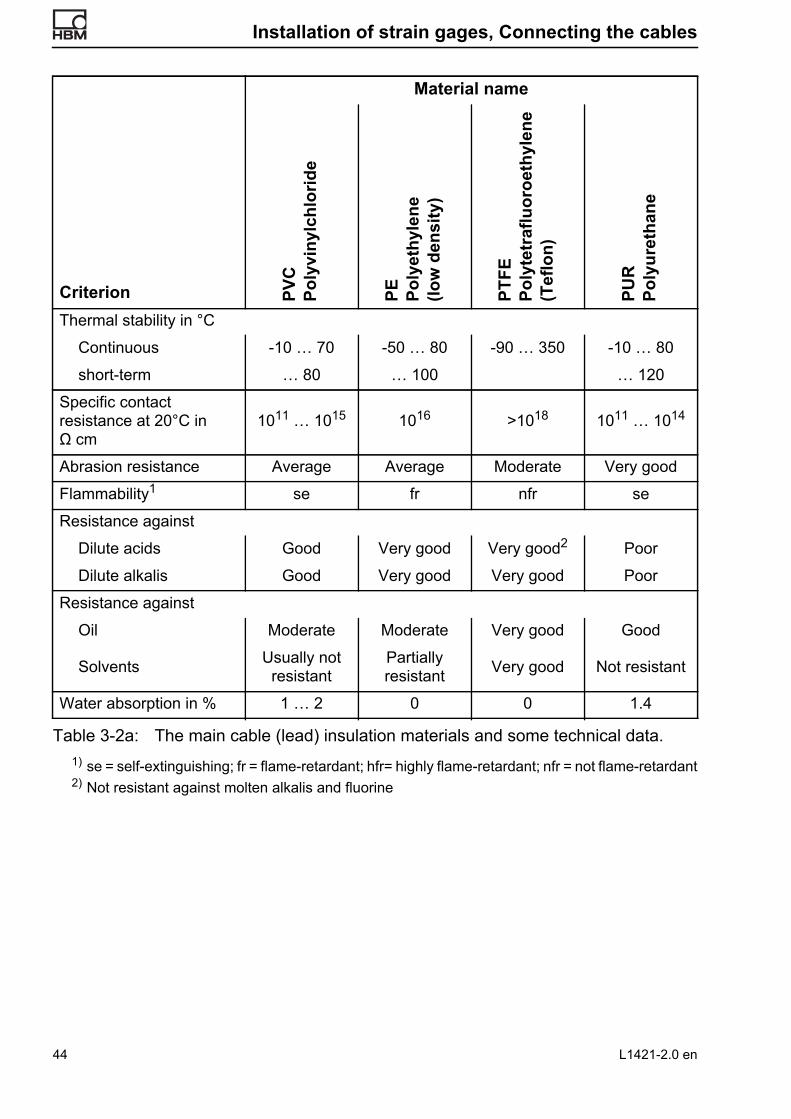
Installation of strain gages, Connecting the cables
Material name
Criterion PVC
Po
lyvi
nylc
hlor
ide
PE
Poly
ethy
lene
(lo
w d
ensi
ty)
PTFE
Po
lyte
traf
luor
oeth
ylen
e (T
eflo
n)
PUR
Po
lyur
etha
ne
Thermal stability in °C
Continuous -10 … 70 -50 … 80 -90 … 350 -10 … 80
short-term … 80 … 100 … 120
Specific contact resistance at 20°C in Ω cm
1011 … 1015 1016 >1018 1011 … 1014
Abrasion resistance Average Average Moderate Very good
Flammability1
1) se = self-extinguishing; fr = flame-retardant; hfr= highly flame-retardant; nfr = not flame-retardant
se fr nfr se
Resistance against
Dilute acids Good Very good Very good2
2) Not resistant against molten alkalis and fluorine
Poor
Dilute alkalis Good Very good Very good Poor
Resistance against
Oil Moderate Moderate Very good Good
Solvents Usually not resistant
Partially resistant Very good Not resistant
Water absorption in % 1 … 2 0 0 1.4
Table 3-2a: The main cable (lead) insulation materials and some technical data.
44 L1421-2.0 en
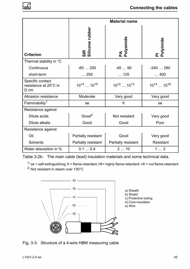
Connecting the cables
Fig. 3-3: Structure of a 4-wire HBM measuring cable
Material name
Criterion SIR
Si
licon
e ru
bber
PA
Poly
amid
e
PI
Poly
imid
e
Thermal stability in °C
Continuous -60 … 200 -40 … 90 -240 … 280
short-term … 250 … 125 … 400
Specific contact resistance at 20°C in Ω cm
1014 … 1015 1012 … 1013 1014 … 1016
Abrasion resistance Moderate Very good Very good
Flammability1
1) se = self-extinguishing; fr = flame-retardant; hfr= highly flame-retardant; nfr = not flame-retardant
se fr se
Resistance against
Dilute acids Good2
2) Not resistant in steam over 130°C
Not resistant Very good
Dilute alkalis Good Good Poor
Resistance against
Oil Partially resistant Good Very good
Solvents Partially resistant Partially resistant Resistant
Water absorption in % 0.1 … 0.4 2 … 10 1 … 3
Table 3-2b: The main cable (lead) insulation materials and some technical data.
a) Sheathb) Shieldc) Protective tubingd) Core insulatione) Wire
e)
c)
b)
a)
d)
L1421-2.0 en 45

Installation of strain gages, Connecting the cables
Note 3.1-6:HBM cables are characterized by a high capacitive symmetry; there are no systematic deviations even with longer cables. Resistive symmetry is essentially insignificant (different resistances of the different wires). A symmetry test can indicate wiring faults during error recognition if there are balancing problems, e.g. in wrong plug connections, soldering connections, or in rare cases defective cables. The concepts below apply to work with CF measuring instruments. Testing with capacitance measurement (measurement frequency 1,000 … 10,000 Hz, where possible):The capacitances 1) 1 + shield to 2 (C1, 2) and 1 + shield to 3 (C1, 3) must be identical in size. Permissible
differences, independent of cable length, are 100 ... 200 pF. (Condition also required for 3-wire cable.)
2) 4 to 2 (C4, 2) and 4 to 3 (C4, 3) must be identical in size. Permissible differences, independent of cable length, are 100 ... 200 pF.
Different capacitance values between the measurements as per 1 and 2 are not significant; the difference is significant due to the shielding connected with 1 (approx. 30%). If no wiring errors are present, any asymmetry exceeding one of the above values can be compensated by additional capacitors. These capacitors can be connected at either end of the cable.
3.2 Practical tips
3.2.1 Soldering tips• Remove oxide from solder terminal tabs before bonding with a glass fibre
eraser, then clean with RMS1 and cotton buds.
• Before soldering the cable, tin the solder tabs: Twist ends of wires together (between paper not bare fingers) and pre-tin. Touch the soldering tip to the soldering object, add enough solder with flux core so that the flux thoroughly wets the solder. If solid solder wire is used, wet the soldering point beforehand with a flux pen (order no. 1-FS01). Use flux and solder sparingly!
• Soldering the cable wires: Lay the tinned wire end on the tinned solder terminal or insert into a solder tag, fix in place if necessary with adhesive tape and solder without adding further solder.
46 L1421-2.0 en

Connecting the cables
Fig. 3-1: Soldering cable wires onto SG with connection leads
A solder terminal should also be set (as can be seen in Fig. 3-1) for SG with open solder tabs (see Fig. 2-4 on Page 29, sketch b). The connection between the solder tab and solder terminal should be flexible. A single strand of the cable wire should be connected from the solder terminal to the solder tab (see Fig. 3-2). Avoid short circuits due to protruding blank wires! If necessary, bond insulating foil underneath.
Fig. 3-2: Connecting cable wires onto SG with open solder tabs
• Keep soldering iron steady during soldering until the solder flows, which should occur within approx. 2 seconds (otherwise the solder joint will overheat).
Adhesive tape or X60
Three-wire connection
Connect strand with relief loop to SG
L1421-2.0 en 47
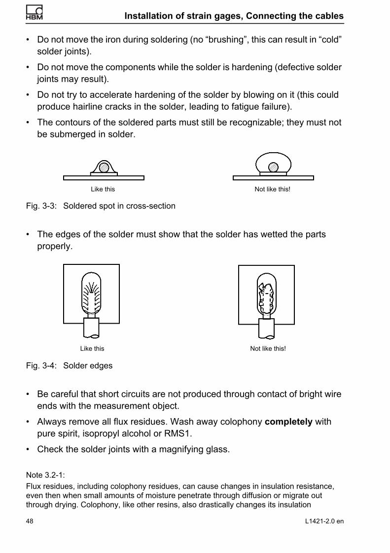
Installation of strain gages, Connecting the cables
• Do not move the iron during soldering (no “brushing”, this can result in “cold” solder joints).
• Do not move the components while the solder is hardening (defective solder joints may result).
• Do not try to accelerate hardening of the solder by blowing on it (this could produce hairline cracks in the solder, leading to fatigue failure).
• The contours of the soldered parts must still be recognizable; they must not be submerged in solder.
Fig. 3-3: Soldered spot in cross-section
• The edges of the solder must show that the solder has wetted the parts properly.
Fig. 3-4: Solder edges
• Be careful that short circuits are not produced through contact of bright wire ends with the measurement object.
• Always remove all flux residues. Wash away colophony completely with pure spirit, isopropyl alcohol or RMS1.
• Check the solder joints with a magnifying glass.
Note 3.2-1:Flux residues, including colophony residues, can cause changes in insulation resistance, even then when small amounts of moisture penetrate through diffusion or migrate out through drying. Colophony, like other resins, also drastically changes its insulation
Like this Not like this!
Like this Not like this!
48 L1421-2.0 en

Connecting the cables
resistance dependent on the temperature. The insulation resistance of a measurement point can be easily measured against the object, but not between the two SG connections. A change in the insulation resistance between these connections does however generate a zero point drift, which is then incorrectly attributed to the SG. Colophony can even act corrosively under unfavorable conditions. It is therefore extremely important to remove all flux residues with great care!
3.2.2 Hints for cable connection • When producing transducers, only use full bridge circuits. Keep the internal
bridge connection lines as short as possible. Ensure that the connection lines in all bridge branches are identical in length (at least the lines in neighboring bridge arms should be the same length).
• Additional strain relief on the measurement cable is recommended, e.g. by bonding the cable end in place with X60 superglue.
Fig. 3-5: Cable connection with X60
The remaining cable can be fixed with cable clips in the usual manner. Adhesive (or screw-on) cable clips are particularly easy to use.
Fig. 3-6: Cable fixing with cable clips
• After connecting the cables, remove all flux residues and check the insulation resistance and cable resistance (contact resistance), see also Note 3.2-1.
• If the measuring point is subject to extreme stresses, e.g. pressurized water or submerged storage for longer periods of time, remove approx. 5 to 10 cm
X60
L1421-2.0 en 49

Installation of strain gages, Connecting the cables
of the cable sheath first so that the cable wires can be individually embedded in the covering medium. This results in long creepage distances at the most endangered spot, the exit of the cable from the protective medium. (For more information about measuring point protection, see Section 5, Page 53.)
Fig. 3-7: Various options for cable fixing with X60
X60 X60 X60
50 L1421-2.0 en

Intermediate tests
4 Intermediate tests
4.1 Visual inspection
Check the SG and cable connections using a good magnifying glass with approx. 6-fold magnification for:• Air bubbles under the SG
• Poorly bonded edges
• Unreliable solder connections
• Flux residues
4.2 SG contact resistance
SG in delivery condition are adjusted to the nominal resistance with a strict tolerance. The control measurement should indicate whether the SG resistance has been significantly changed by incorrect installation (resistance changes up to +0.25% can be tolerated).
4.3 Connection cable resistance
Connection cable resistance can (in unregulated measuring systems with constant voltage supply) apparently reduce SG sensitivity; it should therefore be measured and the value recorded in the test record. The “known systematic deviation” caused by the cable resistance must be corrected when evaluating the measurement.
Note 4.3-1:Example: With a measuring point distance from the amplifier of 20 m and a standard cable with cross-section of 0.17mm2, resistance is 4.23 Ohm (supply and return lines). This results in a sensitivity loss of:
3.4% with an SG resistance of 120 Ohm 1.2% with an SG resistance of 350 Ohm 0.6% with an SG resistance of 700 Ohm
4.4 SG insulation resistance
Measure the SG insulation resistance to ground. Only use instruments with a test voltage below 50 Volt. An SG installed under laboratory conditions should have, at room temperature, an insulation resistance of minimum 20,000 MΩ. At least 2,000 MΩ should be
L1421-2.0 en 51

Installation of strain gages, Intermediate tests
reached in outdoor installations (also see [18]). A lower insulation resistance indicates either insufficient cleaning of the solder joints (see Section 3.2.1, Soldering tips, Page 46), or subsequent contamination, e.g. due to sweaty fingers or absorbed moisture. The latter can occur in humid atmospheres. In this case, the insulation must be heated until a sufficiently high and stable insulation resistance is reached (80 ... 100°C for cold curing adhesives, 120 ... 180°C for hot curing adhesives).
4.5 Connection cable insulation resistance
The insulation resistance between the wires of the connection cable depends on the quality of the insulation materials (see Note 3.1-6) and the length of the cable. It should have a similar magnitude to the insulation resistance of the SG. It can however no longer be measured after installation, as only the SG resistance can then be measured.
52 L1421-2.0 en

Measuring point protection
5 Measuring point protection
SG measuring points must be protected against mechanical or chemical influences. Even under ideal conditions, e.g. in the laboratory, the measuring point properties will be affected over time if suitable countermeasures are not implemented. These countermeasures are as diverse as the influences on the measuring point. Light protection against contact (hand perspiration) may be sufficient in laboratories with dry enough air, while protection in rough rolling mill operations must be proof against vapor, water, oil, heat and mechanical influences. In the first case, a simple varnish seal is appropriate, in the second case a barrier must be built up in several layers of various protective covers. It must be made clear here that absolute protection over unlimited time can only be ensured by hermetically sealed metallic encapsulation. This degree of protection is therefore used in commercial transducers, where the function permits. All other covering agents, even the best, only provide temporary protection. The duration of protection depends both on the type and thickness of the covering agent used and from the type of attacking medium. The protection period ranges from several hours to several years, depending on the circumstances. Which protection period is required depends not only on the required service life of the measuring point, but also on the duration of the individual measurements, the possibility of intermediate zero point checks and finally on the requirements regarding measurement uncertainty. Slight impairments to the measuring point, e.g. caused by migration of moisture due to diffusion, will generally affect the zero point. If these can be controlled, e.g. by relieving the measurement object, and if they are within acceptable limits (e.g. 100 … 200 μm/m), then measurements can still be implemented with a measurement uncertainty acceptable for stress analysis measurements. Insulation resistance is another indicator for the suitability of a measuring point. A reduction in insulation resistance from 1,000 MΩ to 1 MΩ causes a zero point shift of -60 μm/m in a 120 Ω SG, -175 μm/m in a 350 Ω SG and -350 μm/m in a 700 Ω SG! This means that the lower limit of the insulation resistance also depends on the measuring grid resistance of the SG used. The measuring point can be heavily affected by the diffusion of caustic or conductive substances and by corrosion. Corrosion is greatly promoted by the use of DC current to supply the SG! Experience shows that galvanic elements are formed and their voltages are superimposed on the measurement signal, causing large measurement errors (with DC feed!). Finally, it must not be forgotten that the requirements for measuring point protection apply equally to the connection lines, the cables (see also Section 3.1.6, Lead material, Page 42). The protective measures must be effective, but they must not change the properties of the measurement object. Thin objects must not be made so rigid
L1421-2.0 en 53

Installation of strain gages, Measuring point protection
that they cannot be deformed under load; plastics must not be attacked by materials containing solvents. It is not possible to provide definitive instructions for every case. The following hints should however be sufficient to determine the correct measures for the majority of problems that may occur.
5.1 Hints for the use and structure of protective covers for SG measuring points
When selecting the protection materials, consider the following factors: • The ambient conditions (see also [17]: “Chemical resistance of HBM
covering agents”).
• The duration of the measurement or the required service life of the measuring point.
• The required measurement uncertainty.
• The measuring object must not be stiffened in an impermissible manner.
• Material that comes in contact with the measuring point, including the connection cable, must have a very high insulation resistance and must not trigger any chemical reactions or corrosion.
The following applies for the application:
• The measuring point must be in perfect condition before being covered. Adhesives and any other covering agents must be fully cured/hardened. Trapped moisture, perspiration, flux residues from soldering, etc. are like time fuses, leading sooner or later to measurement errors or even failure of the measuring point. Remember that effective covering agents not only keep out external moisture, they also keep internal moisture in!
• The measuring point must be covered directly after installation.
• If SG installation is unavoidable under humid conditions (deadlines, poor weather, humid rooms), the measurement object should be baked dry in an oven (temperature approx. 110 ... 120°C) where possible or, if this is not possible, the measuring point should be dried using a hot air gun (hair dryer, etc.).
• The covering agent must be fully bonded with the area surrounding the measuring point. Defects and capillaries (scratches, grooves) are access points through which aggressive media can migrate. The covering agent bond with the surrounding area must remain unchanged during the entire
54 L1421-2.0 en

Measuring point protection
service life of the measuring point. The surrounding area must therefore be cleaned as thoroughly as the adhesive point and should reach approx. 1 to 2 cm over the outer adhesive edges. Hand perspiration (fingerprints) can cause rust to creep under the covering agent rendering it ineffective, despite the initial perfect condition.
• Cable entries must be very carefully sealed. The covering agent must surround the wire ends on all sides, including from underneath, to ensure that no channels or capillaries form through which moisture could penetrate inside the cover. Embed cable wires individually in the covering agent, in the case of multi-core cables, and cover a part of the cable sheath as well with the covering agent (Fig. 5-1 on Page 55). In critical ambient conditions, roughen the cable insulation first and degrease it with chemically pure solvent.
• Comply with the instructions for use when using commercial covering agents for SG measuring points.
Fig. 5-1: Measuring point with protective cover
5.2 Common covering agents
• Polyurethane varnish PU140 Air-drying varnish. Suitable for light protection against hand contact (perspiration), dust, normal air humidity and the usual humidity fluctuations in moderate climate zones. Also suitable as insulating layer under other
Connection cable
AK22 base for all-round embedding of the cable wires
AK2220
Adhesive edge
5 – 10
L1421-2.0 en 55
Installation of strain gages, Measuring point protection
covering agents, oil resistant, good abrasion resistance. Caution: Do not use in combination with NG150. Complete curing takes 96 hours at room temperature.
• Nitrile rubber varnish NG150 Air-drying varnish. Resistant to oil and gasoline, preferred application for contact with liquefied gases (not oxygen!). Caution: Do not use in combination with PU140.
• Silicone varnish SL450 Hot curing varnish. Used preferentially to protect high temperature installations against moisture absorption and contamination.
• AK22, permanently plastic putty Advantages: Easy application by kneading it on. Excellent adhesion due to strong intrinsic adhesive force. Very good protection against moisture and water; can also be used under water; protection in water at approx. 20°C up to approx. 1 year, water at 75°C up to approx. 3 weeks; tested in pressurized water up to 400 bar for several days, limit values still unknown. Very good weather resistance. Long term protection can be significantly enhanced by kneading on some aluminum (household) foil as a diffusion barrier. Mechanical protection against impacts and falling objects can be easily implemented by pressing some sheet metal onto the self-adhesive putty. Temperature resistance in air -50 … +170°C. Unlimited shelf life.Disadvantages: Not resistant to oils and solvents. Cannot be used externally on objects with high centrifugal forces.
• ABM75, permanently plastic putty with aluminum foilApplication areas and properties similar to AK22, but with the following exceptions: The plate-shaped material is already laminated with a 50 μm thick aluminum foil as a diffusion barrier. The temperature range is -200 … +75°C, whereby the upper limit is set by the start of flowing.
56 L1421-2.0 en

Measuring point protection
• SG200, white, solvent-free silicone rubber Suitable for protection against moisture and weather, against water at room temperature, limited resistance to oil. The rubber-like topcoat offers very good mechanical protection. Temperature resistance: -55 … +200°C, the material remains elastic within this range.
• SG250, transparent, solvent-free silicone rubber Suitable for protection against moisture and weather, against water at room temperature, limited resistance to oil. The rubber-like topcoat offers very good mechanical protection. Temperature resistance: -70 … +250°C, the material remains elastic within this range.
• Vaseline (petroleum jelly), unbleached Advantages: Inexpensive, easy to apply, very good protection against moisture and water, can also be used under water. Disadvantages: Cannot be used in flowing water, rain or spray water; can be easily wiped away accidentally from open surfaces; melts at approx. 50°C.
• Silicone greaseDespite its good properties, the use of silicone grease is not recommended as it easily transfers to tools and from there to other objects. Because of its great adhesion, silicone grease is difficult to remove completely. As it is an excellent release agent, the slightest traces prevent proper bonding of SG.
• Micro-crystalline waxes Good protection against moisture and general atmospheric influences. Must be applied in melted condition on the warmed object to obtain a perfect bond. Low mechanical protection. Temperature range approx. -70 … +100°C.
• Poly-sulfide rubber Two-component material, produces a rubbery mass that is extremely solvent and ageing resistant. It is also characterized by good weather resistance. Temperature range -50 … +120°C.
L1421-2.0 en 57

Installation of strain gages, Measuring point protection
• Epoxy resin (trade names: Araldite, UHU-plus, etc.)Resins that do not set too hard are generally suitable for SG covers. The material available under the trade name UHU-plus, a two-component resin, is primarily suitable as protection against oil, engine fuels, dilute acids, dilute alkalis, numerous solvents and also provides good mechanical protection. Temperature limits are dependent on the curing conditions (cold or hot curing).
• Aluminum adhesive strips Adhesive strips laminated with aluminum foil form a good water vapor barrier (diffusion barrier). As an additional cover for the measuring point, they are suitable for improving the properties of the underlying covering agents, particularly long-term stability. Aluminum foils are also very suitable as additional protective covers for measurement cables which are, in numerous cases, the weakest link in the measuring point.
• Liquid measuring point protection agents Some measuring point protection problems can be resolved by using insulating liquids. One example is the internal installation in a small vessel to be subjected to a pressure test. If a pressure medium other than the usual pressure liquid water is used, numerous problems are resolved in a simple manner. The requirement is that the selected pressure medium offers good insulation properties and is free of additives that could attack the SG. Options include:
• Water-free and acid-free oil
• Paraffin oil
• Pure petroleumThis type of measuring point protection using liquid agents has already been successfully used for the protection of permanently installed measuring points where a surrounding capsule is filled with the protection agent. Another excellent agent can be mentioned in this regard:
Poly-isobutyls, where the low molecular versions can be as liquid as oil or as viscous as honey (trade names: Oppanol B 3, B 10 and B 15.)
• Combined agents A single covering agent is often not enough for sufficient measuring point protection. Examples for combinations of several agents are given by the AK22 and ABM75 (plastic mass plus aluminum foil). In order to add
58 L1421-2.0 en

Measuring point protection
additional mechanical protection to the metal foil, apply an extra layer of e.g. silicone rubber SG250. When producing multi-layer covers, ensure that each layer is fully hardened before applying the next layer. In addition, each layer must overlap the underlying layer by several millimeters on all sides. Frequently, there are several different media acting on a measuring point, e.g. oil and water. In such cases, for example, the oil-soluble ABM75 should be applied directly to the SG, covered with the aluminum foil as a diffusion barrier followed by a oil-resistant epoxy resin as the final layer. Multi-layer protection is absolutely essential for indefinable media such as e.g. seawater. The top layers that do not come into contact with the SG can be made of other materials than those mentioned here, e.g. asphalt. These materials must however not dissolve or chemically change the underlying layers. Apart from that, their electrical insulation resistance is not relevant.
The problem of protecting measuring points is so multi-faceted that only a general overview can be given. In critical cases, prior investigations under application conditions is highly recommended.
L1421-2.0 en 59

Installation of strain gages, Bibliography
6 Bibliography
[1] VDI/VDE-Richtlinie 2635, Blatt 1: Dehnungsmessstreifen mit metallischem Messgitter; Kenngrößen und Prüfbedingungen. Beuth Verlag GmbH, Berlin.
[2] Michel, M.: Adhäsion und Klebetechnik. Carl Hanser Verlag, München (1969).
[3] Mittrop, F.: Das Kleben als Befestigungsverfahren für Dehnungsmeßstreifen in “Haus der Technik e.V. Essen Vortragsveröffentlichungen” Heft 31 (1965), S. 15-27.
[4] DIN 53281, Teil 1: Prüfung von Metallklebstoffen und Metallklebungen – Proben – Klebeflächenvorbehandlung Sept. 1979. Beuth Verlag GmbH, Berlin.
[5] Kleinert, H. und W. Krimmling: Das Alterungsverhalten von Metallklebeverbindungen in Abhängigkeit von der Oberflächenvorbehandlung der Fügeteile. Plaste und Kautschuk 12 (1965), H. 8, S. 472-475.
[6] N.N.: Nullpunktstabilität von DMS-Meßstellen auf Steingut. Meßtechnische Briefe 3. Jg. (1967), H 3, S. 52. Publisher: Hottinger Baldwin Messtechnik GmbH, Darmstadt.
[7] VDI-Richtlinie 3821 (Sept. 1978): Kunststoffkleben, Beuth Verlag GmbH, Berlin.
[8] Merkblatt DVS 2204: Kleben von thermoplastischen Kunststoffen, Teil 2: Polyolefine (Februar 1977). Deutscher Verlag für Schweißtechnik (DVS) GmbH, Düsseldorf.
[9] Oberbach, K., und G. Heese: Dehnungsmeßstreifen-Hilfsmittel zum Prüfen von Kunststoff-Formteilen. Kunststoffe 64 (1974) H. 9, S. 488-493.
[10] Kern, W. F.: Meßelemente für die Anwendung auf Gummiprodukten. VDI-Bildungswerk, Manuskript BW 2556 (1973).
[11] Diehl, K., U. Hanser und W. Hort: Erfassung mechanischer Beanspruchung von Skeletteilen bei der Osteosynthese mittels
60 L1421-2.0 en

Bibliography
Dehnungsmeßstreifen. Medizinisch-orthopädische Technik 95 (1975) H. 3, S. 72-74. A. W. Geutner-Verlag, Stuttgart.
[12] Korber, K. H.: Elektrisches Messen mechanischer Größen in der zahnmedizinischen Grundlagenforschung. Meßtechnische Briefe 6. Jg. (1970) H. 2, S. 38-43. Publisher: Hottinger Baldwin Messtechnik GmbH, Darmstadt.
[13] Kramer, J.: Messung der Zugkräfte bei Anwendung der Wirbelsäulenstreckbandage. Meßtechnische Briefe 6. Jg. (1970) H. 2, S. 44-45. Publisher: Hottinger Baldwin Messtechnik GmbH, Darmstadt.
[14] Windecker, D.: Untersuchungen der Belastbarkeit und der Verformung von zahnärztlichen Prothesen mit Hilfe von Dehnungsmeßstreifen. Meßtechnische Briefe 7. Jg. (1971) H. 2, S. 34-40. Publisher: Hottinger Baldwin Messtechnik GmbH, Darmstadt.
[15] Reuther, J.F.: Druckplattenosteosynthese und freie Knochentransplantation zur Unterkieferrekonstruktion – Experimentelle und klinische Untersuchungen. Med. habil.-Schrift, Johannes Gutenberg-Universität, Mainz (1977).
[16] Macintosh, R.M.: Zinn bei tiefen Temperaturen, Zeitschrift “Zinn und seine Verwendung”, Nr. 72 (1967), S. 6-10.
[17] „Strain gages and accessories“. Hottinger Baldwin Messtechnik GmbH, Darmstadt.
[18] Hoffmann, K.: An Introduction to Measurements using Strain Gages. Publisher: Hottinger Baldwin Messtechnik GmbH, Darmstadt.
L1421-2.0 en 61

Installation of strain gages, Bibliography
62 L1421-2.0 en

Hottinger Baldwin Messtechnik GmbH
Im Tiefen See 45 • 64293 Darmstadt • GermanyTel. +49 6151 803-0 • Fax: +49 6151 803- 9100E-mail: [email protected] • www.hbm.com
© Hottinger Baldwin Messtechnik GmbH.
All rights reserved. All details describe our products in general form only. They are not to be understood as express warranty and do not constitute any liability whatsoever.
L142
1-2.
0 en
7-20
02.1
421