PRE-WIRED STRAIN GAGES · PRE-WIRED STRAIN GAGES PREcISION LINEAR PATTERN ... Linear pattern...
5
E-1 E STRAIN GAGES OMEGA ® KFH SERIES PRE-WIRED STRAIN GAGES U No Soldering at the Measuring Point U Each Gage has 50 mm of PTFE Cable before Transitioning to AWG 28 Leads to Prevent Leads from Adhering During Installation U Short, Medium and Long Grid Linear Gages U Short and Medium Grid XY Gages (T-Rosettes) U Short and Medium Grid 0°/45°/90° Planar Rosettes U Rugged Polyimide Carrier U Fully Encapsulated Gages for Protection from the Environment Proven Omega Quality Strain Gages with Two or Three Wires Attached to Make Installation Easy! Strain gage shown actual size. Fast Delivery! IN STOCK! For Fast Delivery Visit omega.com/kfh
Transcript of PRE-WIRED STRAIN GAGES · PRE-WIRED STRAIN GAGES PREcISION LINEAR PATTERN ... Linear pattern...

E-1
E
ST
RA
IN G
AG
ES
OMEGA® KFH SERIESPRE-WIRED STRAIN GAGES
U No Soldering at the Measuring PointU Each Gage has 50 mm of PTFE Cable
before Transitioning to AWG 28 Leads to Prevent Leads from Adhering During Installation
U Short, Medium and Long Grid Linear Gages
U Short and Medium Grid XY Gages (T-Rosettes)
U Short and Medium Grid 0°/45°/90° Planar Rosettes
U Rugged Polyimide CarrierU Fully Encapsulated Gages for
Protection from the Environment
Proven Omega
Quality Strain Gages
with Two or Three
Wires Attached
to Make
Installation Easy!
Strain gage shown actual size.
Fast Delivery!
IN STOcK! For Fast Delivery
Visit omega.com/kfh
E
ST
RA
IN G
AG
ES
E-2
MODEL NO. DESCRIPTION
TT300 Complete heat cure adhesive kit
SG496 1 oz methyl-based cyanoacrylate (approximately 750 gages)
SG401 0.1 oz ethyl-based cyanoacrylate (approximately 50 gages)
ACCESSORIES
PRE-WIRED STRAIN GAGES PREcISION LINEAR PATTERN
2- or 3-Wire Models120 or 350 Ω0.6 to 20 mm Grid LengthsU Pre-Wired for Fast
InstallationU No Soldering at
Measurement EndU Broad Temperature RangeU 2- or 3-Wire Models U Clear Alignment Marks
Linear pattern precision gages with minature and medium length grids are for general purpose and stress analysis applications. Available with either two 1-meter leads or three 3-meter leads and 120 or 350 Ω resistance. All models are compensated for steel.
* Maximum permitted bridge energizing voltage (Vrms)Ordering Examples: KFH-1.5-120-C1-11L1M2S, a linear 1.5 mm grid, 120 Ω, with two 1 m leads.KFH-3-350-C1-11L3M3S, a linear 3 mm grid, 350 Ω, with three 3 m leads per grid.
KFH Series U Bonds with Hot or Cold Cure Adhesives
U PTFE Wire at Attachment End Prevents Sticking During Installation
To Order Visit omega.com/kfh for Pricing and Details
GAGE PATTERNLeads not shown
MODEL NO.Pkg of 10
NOM. RESIS- TANCE
(Ω)
DIMENSIONS mm (inch)
MAX V* (Vrms)
TEMP COMP
TERMINATION AND
LEAD LENGTH
GRID CARRIER
A B C D
0.3 mm GRIDKFH-03-120-C1-11L1M2R 120 0.3
(0.012)1.96
(0.077)4.5
(0.18)3.9
(0.15)1.5 ST Two 1 m leads
KFH-03-120-C1-11L3M2R 120 1.5 ST Three 3 m leads0.6 mm GRID
0.6_120ZE LY41S-3_2012_09_19 KFH-06-120-C1-11L1M2R 120 0.6 (0.024)
1.1 (0.043)
4.8 (0.19)
3.9 (0.15)
1.5 ST Two 1 m leadsKFH-06-120-C1-11L3M3R 120 1.5 ST Three 3 m leads1.5 mm GRID
1.5_120ZE LY41S-3_2012_09_19 KFH-1.5-120-C1-11L1M2R 120 1.5 (0.059)
1.5 (0.059)
5.8 (0.23)
3.9 (0.15)
2.5 ST Two 1 m leadsKFH-1.5-120-C1-11L3M3R 120 2.5 ST Three 3 m leads3 mm GRIDKFH-3-120-C1-11L1M2R 120
3.0 (0.118)
2.0 (0.079)
7.4 (0.29)
3.9 (0.15)
4 ST Two 1 m leads
3_120ZE LY41S-3_2012_09_19 KFH-3-120-C1-11L3M3R 120 4 ST Three 3 m leadsKFH-3-350-C1-11L1M2R 350 9 ST Two 1 m leadsKFH-3-350-C1-11L3M3R 350 9 ST Three 3 m leads6 mm GRIDKFH-6-120-C1-11L1M2R 120
6.0 (0.24)
2.0 (0.079)
10.5 (0.41)
3.9 (0.15)
8 ST Two 1 m leads
6_120ZE LY41S-3_2012_09_19 KFH-6-120-C1-11L3M3S 120 8 ST Three 3 m leadsKFH-6-350-C1-11L1M2R 350 15 ST Two 1 m leadsKFH-6-350-C1-11L3M3R 350 15 ST Three 3 m leads10 mm GRID
10_120ZE LY41S-3_2012_09_19 KFH-10-120-C1-11L1M2R 120 10 (0.39)
3.0 (0.12)
14.8 (0.58)
4.8 (0.19)
14 ST Two 1 m leadsKFH-10-120-C1-11L3M3R 120 14 ST Three 3 m leads
20_120ZE LY41S-3_2012_09_19
20 mm GRIDKFH-20-120-C1-11L1M2R 120 20
(0.79)3.0
(0.12)25.2
(0.99)4.8
(0.19)7 ST Two 1 m leads
KFH-20-120-C1-11L3M3R 120 7 ST Three 3 m leads
Shown actual size, 20 mm
Shown larger than actual size, 0.6 mm
Shown larger than actual size, 1.5 mm
Shown actual size, 3 mm
Shown actual size, 6 mm
Shown actual size, 10 mm
S-DM
S 0,3/120ZE LY41S-3
Shown larger than actual size, 0.3 mm
Strain gage shown larger than actual size.
E-3
E
ST
RA
IN G
AG
ES
To Order Visit omega.com/kfh for Pricing and Details
GAGE PATTERNLeads not shown
MODEL NO.Pkg of 10
NOM. RESIS- TANCE
(Ω)
DIMENSIONS mm (inch)
MAX V* (VRMS)
TEMP COMP
TERMINATION AND
LEAD LENGTH PER GRID
GRID CARRIER
A B C D
0.6 mm GRID
06_120ZE XY31S-3_2012_09_19 KFH-06-120-D16-11L1M2S 120 0.6 (0.024)
1.0 (0.039)
5.1 (0.20)
6.9 (0.27)
1.5 ST Two 1 m leads
KFH-06-120-D16-11L3M3S 120 1.5 ST Three 3 m leads
1.5 mm GRID
1.5_120ZE XY31S-3_2012_09_19 KFH-1.5-120-D16-11L1M2S 120 1.5 (0.059)
1.6 (0.063)
5.8 (0.23)
6.9 (0.27)
3 ST Two 1 m leads
KFH-1.5-120-D16-11L3M3S 120 3 ST Three 3 m leads
3 mm GRID
KFH-3-120-D16-11L1M2S 120
3.0 (0.12)
3.2 (0.13)
7.5 (0.30)
9.4 (0.37)
5.5 ST Two 1 m leads
3_120ZE XY31S-3_2012_09_19 KFH-3-120-D16-11L3M3S 120 5.5 ST Three 3 m leads
KFH-3-350-D16-11L1M2S 350 10 ST Two 1 m leads
KFH-3-350-D16-11L3M3S 350 10 ST Three 3 m leads
6 mm GRID
KFH-6-120-D16-11L1M2S 120
6.0 (0.24)
6.3 (0.25)
11 (0.43)
16 (0.63)
11 ST Two 1 m leads
6_120ZE XY31S-3_2012_09_19 KFH-6-120-D16-11L3M3S 120 11 ST Three 3 m leads
KFH-6-350-D16-11L1M2S 350 20 ST Two 1 m leads
KFH-6-350-D16-11L3M3S 350 20 ST Three 3 m leads
MODEL NO. DESCRIPTION
TT300 Complete heat cure adhesive kit
SG496 1 oz methyl-based cyanoacrylate (approximately 750 gages)
SG401 0.1 oz ethyl-based cyanoacrylate (approximately 50 gages)
ACCESSORIES
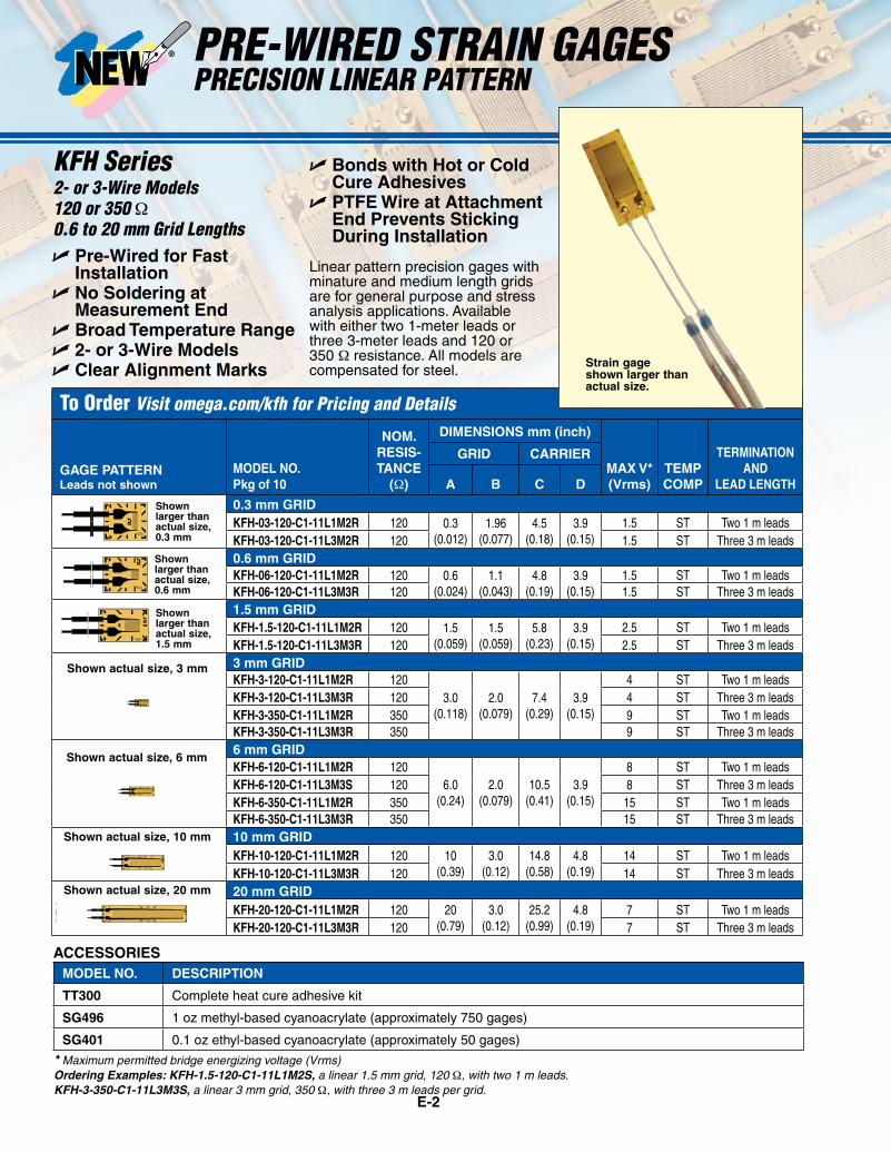
PRE-WIRED STRAIN GAGESPREcISION PLANAR X-Y PATTERN
2- or 3-Wire Models120 or 350 Ω0.6 to 6 mm Grid Lengths
U Pre-Wired for Fast Installation
U No Soldering at Measurement End
U Broad Temperature RangeU 2- or 3-Wire ModelsU Clear Alignment Marks
The planar XY pattern allows precision strain measurement by eliminating the errors often associated with a stacked XY pattern. These gages are available with either two 1-meter leads or three 3-meter leads per grid and are compensated for steel.
* Maximum permitted bridge energizing voltage (Vrms)Ordering Examples: KFH-1.5-120-D16-11L1M2S, two 1.5 mm grids in a planar XY pattern, 120 Ω, with two 1 m leads per grid. KFH-3-350-D16-11L3M3S, two 3 mm grids in a planar XY pattern, 350 Ω, with three 3 m leads per grid.
Shown larger than actual size, 0.6 mm
Shown larger than actual size, 1.5 mm
Shown actual size, 3 mm
Shown actual size, 6 mm
KFH Series U Bonds with Hot or Cold Cure Adhesives
U PTFE Wire at Attachment End Prevents Sticking During Installation
Strain gage shown larger than actual size.
E
ST
RA
IN G
AG
ES
E-4
To Order Visit omega.com/kfh for Pricing and Details
GAGE PATTERNLeads not shown
MODEL NO.Pkg of 10
NOM. RESIS- TANCE
(Ω)
DIMENSIONS mm (inch)
MAX V* (VRMS)
TEMP COMP
TERMINATION AND
LEAD LENGTH PER GRID
GRID CARRIER
A B C D
0.6 mm GRID
06_120ZE RY81S-3_2012_09_19 KFH-06-120-D17-11L1M2S 120 0.6 (0.024)
1.1 (0.043)
4.8 (0.19)
9.9 (0.39)
1.6 ST Two 1 m leads
KFH-06-120-D17-11L3M3S 120 1.6 ST Three 3 m leads
1.5 mm GRID
1.5_120ZE RY81S-3_2012_09_19 KFH-1.5-120-D17-11L1M2S 120 1.5 (0.059)
1.5 (0.059)
5.8 (0.23)
10.2 (0.40)
2.5 ST Two 1 m leads
KFH-1.5-120-D17-11L3M3S 120 2.5 ST Three 3 m leads
3 mm GRID
KFH-3-120-D17-11L1M2S 120
3.0 (0.12)
2.0 (0.079)
7.4 (0.29)
13.9 (0.55)
3 ST Two 1 m leads
3_120ZE RY81S-3_2012_09_19 KFH-3-120-D17-11L3M3S 120 3 ST Three 3 m leads
KFH-3-350-D17-11L1M2S 350 5.5 ST Two 1 m leads
KFH-3-350-D17-11L3M3S 350 5.5 ST Three 3 m leads
6 mm GRID
KFH-6-120-D17-11L1M2S 120
6.0 (0.24)
2.0 (0.079)
10.5 (0.41)
18.7 (0.74)
7.5 ST Two 1 m leads
6_120ZE RY81S-3_2012_09_19 KFH-6-120-D17-11L3M3S 120 7.5 ST Three 3 m leads
KFH-6-350-D17-11L1M2S 350 13 ST Two 1 m leads
KFH-6-350-D17-11L3M3S 350 13 ST Three 3 m leads
MODEL NO. DESCRIPTION
TT300 Complete heat cure adhesive kit
SG496 1 oz methyl-based cyanoacrylate (approximately 750 gages)
SG401 0.1 oz ethyl-based cyanoacrylate (approximately 50 gages)
ACCESSORIES
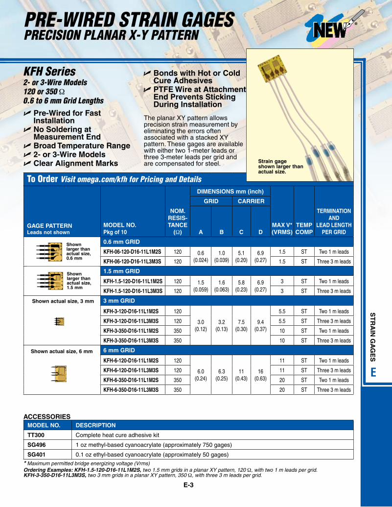
PRE-WIRED STRAIN GAGESPLANAR 0°/45°/90° ROSETTE PATTERN
2- or 3-Wire Models120 or 350 Ω0.6 to 6 mm Grid LengthsU Pre-Wired for Fast
InstallationU No Soldering at
Measurement EndU Broad Temperature RangeU 2- or 3-Wire ModelsU Clear Alignment Marks
The planar rosette pattern allows precision strain measurement by eliminating the errors often associated with a stacked pattern. These gages are available with either two 1-meter leads or three 3-meter leads per grid and are compensated for steel.
* Maximum permitted bridge energizing voltage (Vrms)Ordering Examples: KFH-1.5-120-D17-11L1M2S, three 1.5 mm grids in a planar 0°/45°/90° pattern, 120 Ω, with two 1 m leads per grid.KFH-3-350-D17-11L3M3S, three 3 mm grids in a planar 0°/45°/90° pattern, 350 Ω, with three 3 m leads per grid.
Shown larger than actual size, 0.6 mm
Shown larger than actual size, 1.5 mm
Shown actual size, 3 mm
Shown actual size, 6 mm
U Bonds with Hot or Cold Cure Adhesives
U PTFE Wire at Attachment End Prevents Sticking During Installation
KFH Series
Strain gage shown larger than actual size.
E-5
E
ST
RA
IN G
AG
ES
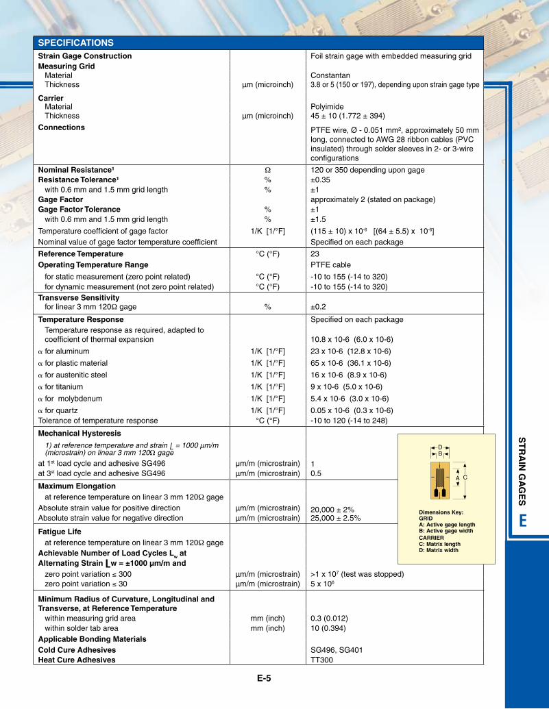
SPECIFICATIONSStrain Gage Construction Foil strain gage with embedded measuring gridMeasuring Grid
Material ConstantanThickness µm (microinch) 3.8 or 5 (150 or 197), depending upon strain gage type
CarrierMaterial PolyimideThickness µm (microinch) 45 ± 10 (1.772 ± 394)
Connections PTFE wire, Ø - 0.051 mm², approximately 50 mm long, connected to AWG 28 ribbon cables (PVC insulated) through solder sleeves in 2- or 3-wire configurations
Nominal Resistance¹ Ω 120 or 350 depending upon gageResistance Tolerance¹ % ±0.35
with 0.6 mm and 1.5 mm grid length % ±1Gage Factor approximately 2 (stated on package)Gage Factor Tolerance % ±1
with 0.6 mm and 1.5 mm grid length % ±1.5
Temperature coefficient of gage factor 1/K [1/°F] (115 ± 10) x 10-6 [(64 ± 5.5) x 10-6]Nominal value of gage factor temperature coefficient Specified on each package
Reference Temperature °C (°F) 23Operating Temperature Range PTFE cable
for static measurement (zero point related) °C (°F) -10 to 155 (-14 to 320)for dynamic measurement (not zero point related) °C (°F) -10 to 155 (-14 to 320)
Transverse Sensitivityfor linear 3 mm 120Ω gage % ±0.2
Temperature Response Specified on each packageTemperature response as required, adapted to coefficient of thermal expansion 10.8 x 10⁻⁶ (6.0 x 10⁻⁶)
a for aluminum 1/K [1/°F] 23 x 10-6 (12.8 x 10⁻⁶)
a for plastic material 1/K [1/°F] 65 x 10-6 (36.1 x 10⁻⁶)
a for austenitic steel 1/K [1/°F] 16 x 10-6 (8.9 x 10⁻⁶)
a for titanium 1/K [1/°F] 9 x 10⁻⁶ (5.0 x 10⁻⁶)
a for molybdenum 1/K [1/°F] 5.4 x 10⁻⁶ (3.0 x 10⁻⁶)
a for quartz 1/K [1/°F] 0.05 x 10⁻⁶ (0.3 x 10⁻⁶)Tolerance of temperature response °C (°F) -10 to 120 (-14 to 248)
Mechanical Hysteresis
10.5
1) at reference temperature and strain L = 1000 µm/m (microstrain) on linear 3 mm 120Ω gage
at 1st load cycle and adhesive SG496 µm/m (microstrain)at 3st load cycle and adhesive SG496 µm/m (microstrain)
Maximum Elongation
20,000 ± 2%25,000 ± 2.5%
at reference temperature on linear 3 mm 120Ω gageAbsolute strain value for positive direction µm/m (microstrain)Absolute strain value for negative direction µm/m (microstrain)
Fatigue Lifeat reference temperature on linear 3 mm 120Ω gage
Achievable Number of Load Cycles Lw at Alternating Strain Lw = ±1000 µm/m and
zero point variation ≤ 300 µm/m (microstrain) >1 x 10⁷ (test was stopped)zero point variation ≤ 30 µm/m (microstrain) 5 x 10⁶
Minimum Radius of Curvature, Longitudinal and Transverse, at Reference Temperature
within measuring grid area mm (inch) 0.3 (0.012)within solder tab area mm (inch) 10 (0.394)
Applicable Bonding MaterialsCold Cure Adhesives SG496, SG401Heat Cure Adhesives TT300
BD
A C
1 2 3 4 5
STRAIN GAGE (with LY41, LY42, LY43 table)
Dimensions Key:GRID A: Active gage length B: Active gage widthCARRIERC: Matrix length D: Matrix width