Page 1 Multi-Axis Surface Machining -...
162
Multi-Axis Surface Machining Preface What's New Getting Started Open the Part to Machine Create a Multi-Axis Sweeping Operation Replay the Toolpath Create a Multi-Axis Contour Driven Operation Create a Multi-Axis Curve Machining Operation Generate NC Code User Tasks Multi-Axis Milling Operations Multi-Axis Sweeping: Lead and Tilt Multi-Axis Sweeping: Fixed Multi-Axis Sweeping: Thru a Point Multi-Axis Sweeping: Normal to Line Multi-Axis Sweeping: 4-Axis Lead/Lag Multi-Axis Sweeping: Optimized Lead Multi-Axis Contour Driven: Between Contours Multi-axis Contour Driven: Parallel Contours Multi-Axis Contour Driven: Spine Contour Multi-Axis Curve Machining: Contact Multi-Axis Curve Machining: Between Two Curves with Tool Axis Interpolation Multi-Axis Curve Machining: Between Two Curves with Tangent Axis Guidance Multi-Axis Curve Machining: Between Curve and Part Multi-Axis Isoparametric Machining: Lead and Tilt Multi-Axis Isoparametric Machining: 4-Axis Lead/Lag Multi-Axis Isoparametric Machining: Interpolation Auxiliary Operations Part Operations, Manufacturing Programs and Machining Processes NC Manufacturing Entities Verification, Simulation and Program Output Workbench Description Menu Bar Toolbars Specification Tree 1 Page Multi-Axis Surface Machining Version 5 Release 13
Transcript of Page 1 Multi-Axis Surface Machining -...
Multi-Axis Surface Machining
Preface
What's New
Getting Started
Open the Part to Machine
Create a Multi-Axis Sweeping Operation
Replay the Toolpath
Create a Multi-Axis Contour Driven Operation
Create a Multi-Axis Curve Machining Operation
Generate NC Code
User Tasks
Multi-Axis Milling Operations
Multi-Axis Sweeping: Lead and Tilt
Multi-Axis Sweeping: Fixed
Multi-Axis Sweeping: Thru a Point
Multi-Axis Sweeping: Normal to Line
Multi-Axis Sweeping: 4-Axis Lead/Lag
Multi-Axis Sweeping: Optimized Lead
Multi-Axis Contour Driven: Between Contours
Multi-axis Contour Driven: Parallel Contours
Multi-Axis Contour Driven: Spine Contour
Multi-Axis Curve Machining: Contact
Multi-Axis Curve Machining: Between Two Curves with Tool Axis Interpolation
Multi-Axis Curve Machining: Between Two Curves with Tangent Axis Guidance
Multi-Axis Curve Machining: Between Curve and Part
Multi-Axis Isoparametric Machining: Lead and Tilt
Multi-Axis Isoparametric Machining: 4-Axis Lead/Lag
Multi-Axis Isoparametric Machining: Interpolation
Auxiliary Operations
Part Operations, Manufacturing Programs and Machining Processes
NC Manufacturing Entities
Verification, Simulation and Program Output
Workbench Description
Menu Bar
Toolbars
Specification Tree
1Page Multi-Axis Surface Machining Version 5 Release 13
Customizing
NC Manufacturing Settings
General
Resources
Operation
Output
Program
Photo / Video
Reference Information
Multi-Axis Sweeping
Multi-Axis Isoparametric Machining
Multi-Axis Contour Driven
Multi-Axis Curve Machining
Collision Checking
Methodology
Glossary
Index
2Page Multi-Axis Surface Machining Version 5 Release 13
PrefaceMulti-Axis Surface Machining enables you to produce NC programs dedicated to machining parts designed in 3D wireframe or solids geometry using multi-axis machining techniques.
Based on industry recognized and leading edge technologies, Multi-Axis Surface Machining provides tight integration between tool path definition, verification and modification.
Multi-Axis Surface Machining is an add-on product to 3-Axis Surface Machining. Thus, the user benefits from superior 3-axis multiple surface machining and leading edge 5-axis simultaneous machining tightly integrated in a flexible NC Programming workbench.
Multi-Axis Surface Machining is particularly adapted for mockup and die machining in automotive domains where the use of 5-axis simultaneous machining brings unequalled surface quality. Moreover, it is targeted at prototype machining, 5-axis trimming and special machining where full 5-axis machining is the requirement for quick and accurate manufacturing.
Multi-Axis Surface Machining is also an add-on product to Prismatic Machining and Lathe Machining.
As an add-on product, it takes advantage of functions such as material removal simulation and NC data generation. It adds the following dedicated multi-axis surface machining techniques to the capabilities offered by the other NC Machining products:
● Multiple surface machining with various tool path styles
● Capability to machine the entire surface with full collision avoidance of the tool holder and cutter active part
● Multiple curve machining with various tool path styles for programming quickly and efficiently grooving, engraving, swarf cutting, flank machining for any desired area
● Various tool axis strategies including dynamic tool axis orientation for both multiple surface and multiple curve machining
● Complete toolkit for controlled and collision free transition tool paths provided for both multiple surface and multiple curve machining.
Certain portions of this product contain elements subject to copyright owned by the following entities:
© Copyright LightWork Design Ltd., all rights reserved.© Copyright Deneb Robotics Inc., all rights reserved.© Copyright Cenit, all rights reserved.© Copyright Intelligent Manufacturing Software, all rights reserved.© Copyright WALTER Informationssysteme GmbH, all rights reserved.© Copyright ICAM Technologies Corporation, all rights reserved.
3Page Multi-Axis Surface Machining Version 5 Release 13
What's New?
Enhanced Functionalities
5-Axis Contour Driven MachiningCapability to specify different offsets and tool positions on guides in 'Between Contour' mode. Allows to faster definition the area to be machined without creating additional geometry.
Improved Cutter compensation3D Contact compensation available for all multi-axis operations.
Enhancements brought to the NC Manufacturing InfrastructureThis product benefits from enhancements to the infrastructure's general functions (NC resources, design changes, simulation, NC data output, 3D PLM integration, and so on).
4Page Multi-Axis Surface Machining Version 5 Release 13

Getting StartedBefore getting into the detailed instructions for using Multi-Axis Machining, this tutorial is intended to give you a feel of what you can accomplish with the product.
It provides the following step-by-step scenario that shows you how to use some of the key functionalities.
Open the Part to MachineCreate a Multi-Axis Sweeping Operation
Replay the ToolpathCreate a Multi-Axis Contour Driven OperationCreate a Multi-Axis Curve Machining Operation
Generate NC Code
5Page Multi-Axis Surface Machining Version 5 Release 13

Open the Part to MachineThis first task shows you how to open a part and enter the Surface Machining workbench.
1. Select File > Open then select the MultiAxisMilling01.CATPart document.
2. Select NC Manufacturing > Surface Machining from the Start menu. The Surface Machining workbench appears. The part is displayed in the Set Up Editor window along with the manufacturing specification tree.
3. Double click Part Operation.1 in the tree. The Part Operation dialog box appears.
4. Select the Machine icon to access the Machine Editor dialog box. Select the 5-axis Machine icon then
click OK to return to the Part Operation dialog box.
5. Click OK to accept the Part Operation.
6. Select Manufacturing Program.1 in the tree to make it the current entity.
To insert program entities such as machining operations, tools and auxiliary commands you can either: ● make the program current before clicking the insert program entity command
● click the insert program entity command then make the program current.
6Page Multi-Axis Surface Machining Version 5 Release 13
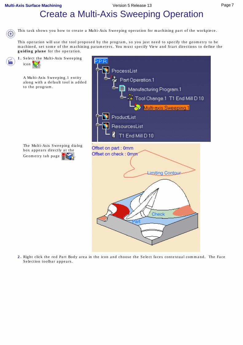
Create a Multi-Axis Sweeping OperationThis task shows you how to create a Multi-Axis Sweeping operation for machining part of the workpiece.
This operation will use the tool proposed by the program, so you just need to specify the geometry to be machined, set some of the machining parameters. You must specify View and Start directions to define the guiding plane for the operation.
1. Select the Multi-Axis Sweeping
icon .
A Multi-Axis Sweeping.1 entity along with a default tool is added to the program.
The Multi-Axis Sweeping dialog box appears directly at the
Geometry tab page .
2. Right click the red Part Body area in the icon and choose the Select faces contextual command. The Face Selection toolbar appears.
7Page Multi-Axis Surface Machining Version 5 Release 13
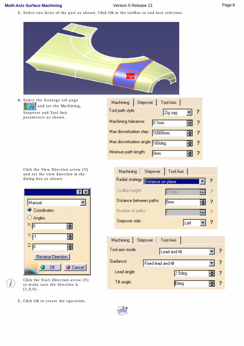
3. Select two faces of the part as shown. Click OK in the toolbar to end face selection.
4. Select the Strategy tab page
and set the Machining,
Stepover and Tool Axis parameters as shown.
Click the View Direction arrow (V) and set the view direction in the dialog box as shown.
Click the Start Direction arrow (S) to make sure the direction is (1,0,0).
5. Click OK to create the operation.
8Page Multi-Axis Surface Machining Version 5 Release 13
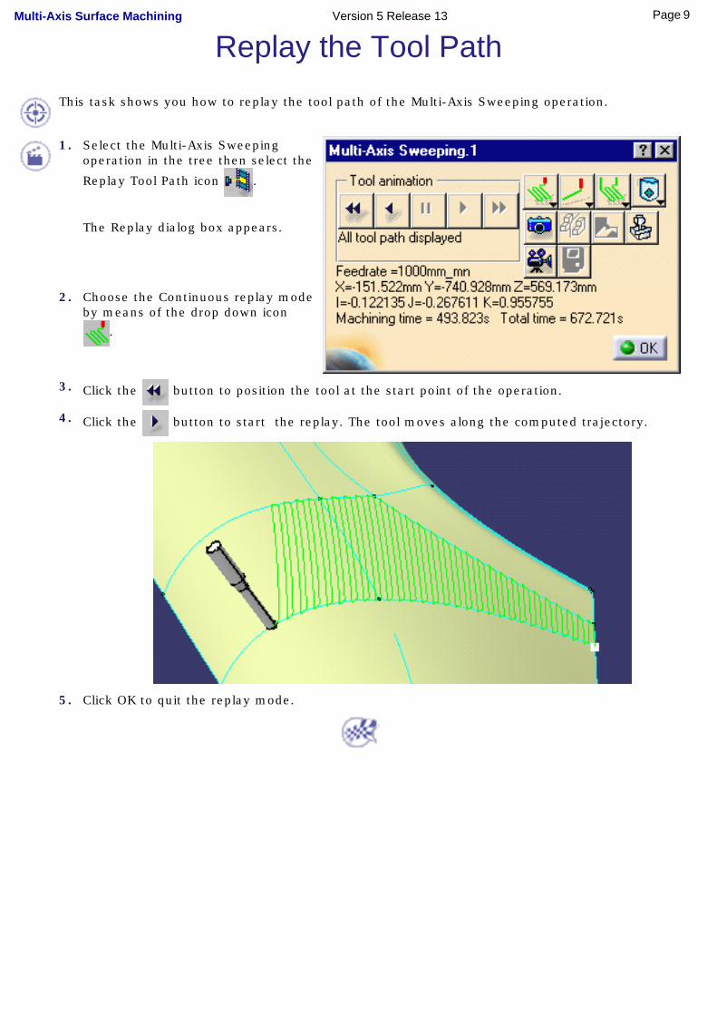
Replay the Tool PathThis task shows you how to replay the tool path of the Multi-Axis Sweeping operation.
1. Select the Multi-Axis Sweeping operation in the tree then select the
Replay Tool Path icon .
The Replay dialog box appears.
2. Choose the Continuous replay mode by means of the drop down icon
.
3. Click the button to position the tool at the start point of the operation.
4. Click the button to start the replay. The tool moves along the computed trajectory.
5. Click OK to quit the replay mode.
9Page Multi-Axis Surface Machining Version 5 Release 13

Create a Multi-Axis Contour Driven OperationThis task shows you how to create a Multi-Axis Contour Driven operation to machine part of the workpiece.
You will specify the geometry to be machined, set some of the machining parameters and select a new tool.
Make sure that the Multi-Axis Sweeping operation is the current entity in the program.
1. Select the Multi-Axis Contour Driven icon .
The Multi-Axis Contour Driven dialog box appears directly at the Geometry page .
2. Right click the red Part Body area in the icon and choose the Select faces contextual command.
The Face Selection toolbar appears. Select the face to be machined and click OK in the toolbar.
3. Select the Strategy tab page
and set the parameters
as shown.
This operation will use a Between Contours strategy and the tool axis will be guided in Fixed Lead and Tilt mode.
The other parameters are the same as the previous operation. However, in the Stepover tab page you can set the Radial Strategy to Distance on Part.
4. Click the View Direction arrow (V) and set the view direction to (0, -1, 0) in the dialog box.
10Page Multi-Axis Surface Machining Version 5 Release 13
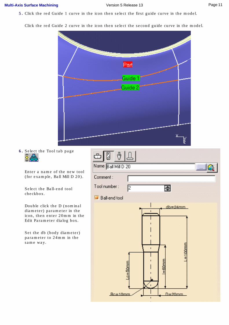
5. Click the red Guide 1 curve in the icon then select the first guide curve in the model.
Click the red Guide 2 curve in the icon then select the second guide curve in the model.
6. Select the Tool tab page
.
Enter a name of the new tool (for example, Ball Mill D 20).
Select the Ball-end tool checkbox.
Double click the D (nominal diameter) parameter in the icon, then enter 20mm in the Edit Parameter dialog box.
Set the db (body diameter) parameter to 24mm in the same way.
11Page Multi-Axis Surface Machining Version 5 Release 13
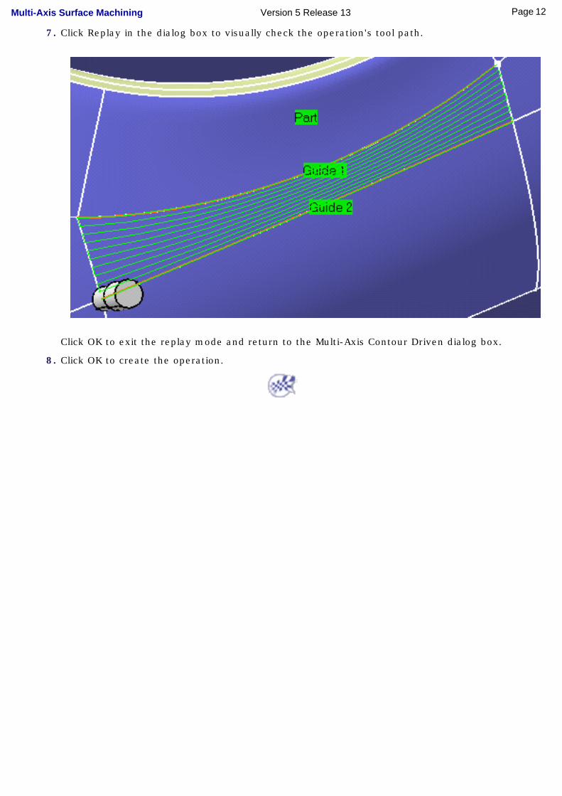
7. Click Replay in the dialog box to visually check the operation's tool path.
Click OK to exit the replay mode and return to the Multi-Axis Contour Driven dialog box.
8. Click OK to create the operation.
12Page Multi-Axis Surface Machining Version 5 Release 13
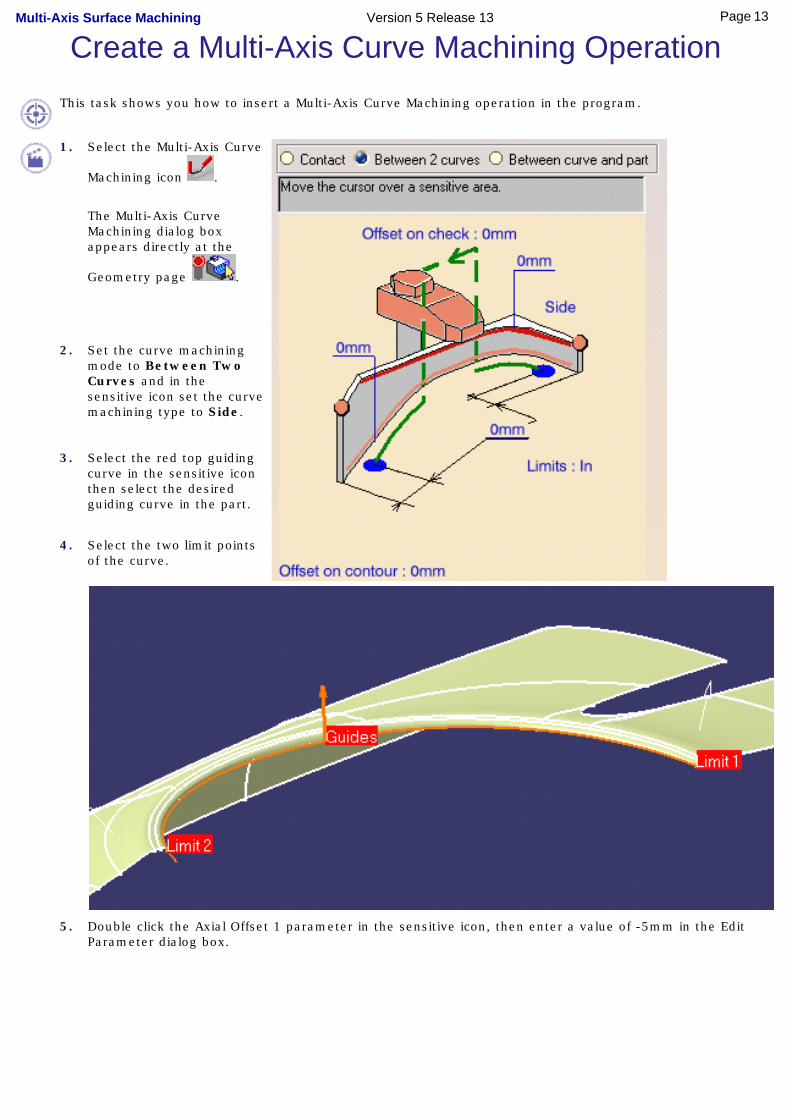
Create a Multi-Axis Curve Machining OperationThis task shows you how to insert a Multi-Axis Curve Machining operation in the program.
1. Select the Multi-Axis Curve
Machining icon .
The Multi-Axis Curve Machining dialog box appears directly at the
Geometry page .
2. Set the curve machining mode to Between Two Curves and in the sensitive icon set the curve machining type to Side.
3. Select the red top guiding curve in the sensitive icon then select the desired guiding curve in the part.
4. Select the two limit points of the curve.
5. Double click the Axial Offset 1 parameter in the sensitive icon, then enter a value of -5mm in the Edit Parameter dialog box.
13Page Multi-Axis Surface Machining Version 5 Release 13
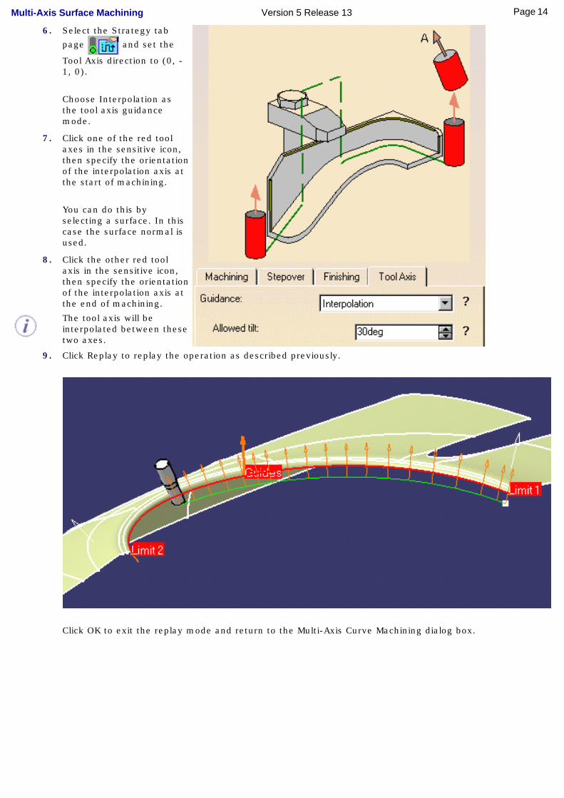
6. Select the Strategy tab
page and set the
Tool Axis direction to (0, -1, 0).
Choose Interpolation as the tool axis guidance mode.
7. Click one of the red tool axes in the sensitive icon, then specify the orientation of the interpolation axis at the start of machining.
You can do this by selecting a surface. In this case the surface normal is used.
8. Click the other red tool axis in the sensitive icon, then specify the orientation of the interpolation axis at the end of machining.
The tool axis will be interpolated between these two axes.
9. Click Replay to replay the operation as described previously.
Click OK to exit the replay mode and return to the Multi-Axis Curve Machining dialog box.
14Page Multi-Axis Surface Machining Version 5 Release 13
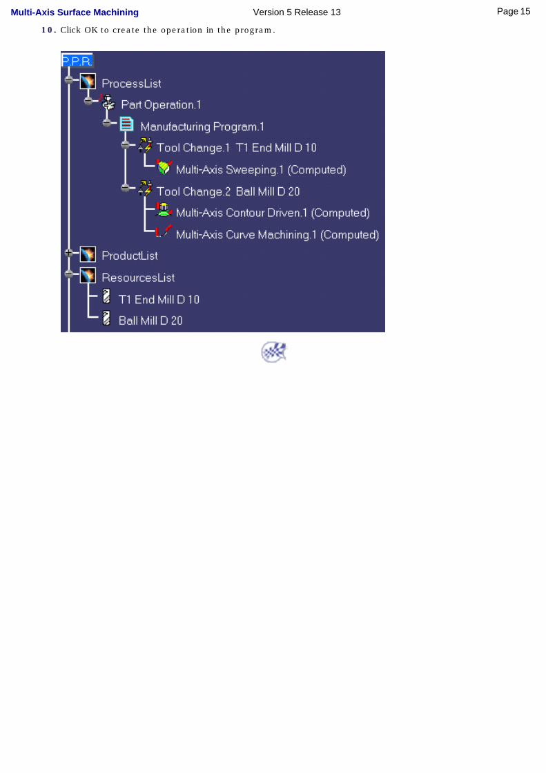
10. Click OK to create the operation in the program.
15Page Multi-Axis Surface Machining Version 5 Release 13
Generate NC Code
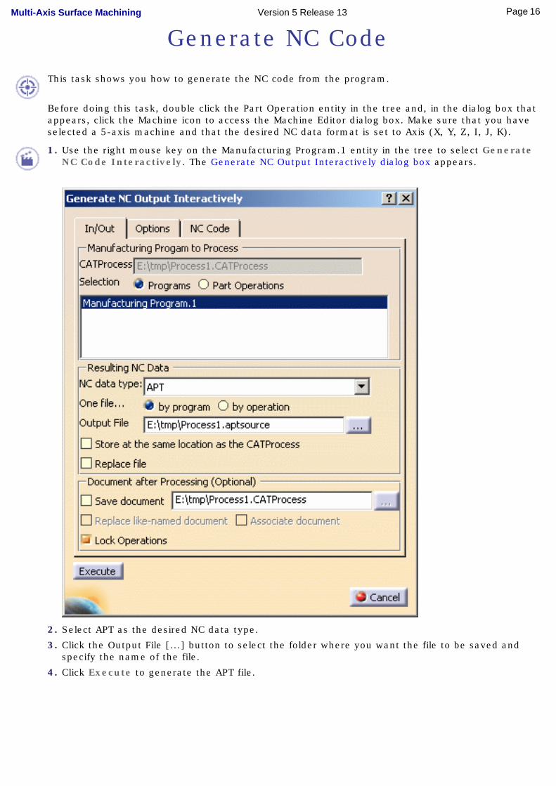
This task shows you how to generate the NC code from the program.
Before doing this task, double click the Part Operation entity in the tree and, in the dialog box that appears, click the Machine icon to access the Machine Editor dialog box. Make sure that you have selected a 5-axis machine and that the desired NC data format is set to Axis (X, Y, Z, I, J, K).
1. Use the right mouse key on the Manufacturing Program.1 entity in the tree to select Generate NC Code Interactively. The Generate NC Output Interactively dialog box appears.
2. Select APT as the desired NC data type.
3. Click the Output File [...] button to select the folder where you want the file to be saved and specify the name of the file.
4. Click Execute to generate the APT file.
16Page Multi-Axis Surface Machining Version 5 Release 13
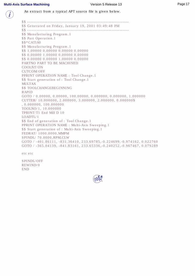
An extract from a typical APT source file is given below.
$$ -----------------------------------------------------------------$$ Generated on Friday, January 19, 2001 03:49:48 PM$$ -----------------------------------------------------------------$$ Manufacturing Program.1$$ Part Operation.1$$*CATIA0$$ Manufacturing Program.1$$ 1.00000 0.00000 0.00000 0.00000$$ 0.00000 1.00000 0.00000 0.00000$$ 0.00000 0.00000 1.00000 0.00000PARTNO PART TO BE MACHINEDCOOLNT/ONCUTCOM/OFFPPRINT OPERATION NAME : Tool Change.1$$ Start generation of : Tool Change.1MULTAX$$ TOOLCHANGEBEGINNINGRAPIDGOTO / 0.00000, 0.00000, 100.00000, 0.000000, 0.000000, 1.000000CUTTER/ 10.000000, 2.000000, 3.000000, 2.000000, 0.000000$, 0.000000, 100.000000TOOLNO/1, 10.000000TPRINT/T1 End Mill D 10LOADTL/1$$ End of generation of : Tool Change.1PPRINT OPERATION NAME : Multi-Axis Sweeping.1$$ Start generation of : Multi-Axis Sweeping.1FEDRAT/ 1000.0000,MMPMSPINDL/ 70.0000,RPM,CLWGOTO / -401.86111, -831.36410, 233.69785,-0.224699,-0.974162, 0.022760GOTO / -365.04139, -841.83161, 233.65336,-0.240252,-0.967467, 0.079289
etc etc
SPINDL/OFFREWIND/0END
17Page Multi-Axis Surface Machining Version 5 Release 13

User TasksThe user tasks you will perform with Multi-Axis Surface Machining involve creating, editing and managing machining operations and other NC manufacturing entities.
Multi-Axis Milling OperationsAuxiliary Operations
Part Operations, Manufacturing Programs and Machining ProcessesNC Manufacturing Entities
Verification, Simulation and Program Output
18Page Multi-Axis Surface Machining Version 5 Release 13
Multi-Axis Machining OperationsThe tasks in this section show you how to create multi-axis machining operations in your manufacturing program.
Create a Multi-Axis Sweeping machining operation: ● Select the Multi-Axis Sweeping icon then select the geometry to be machined. You can use Offset
Groups and Features when defining geometry.
● Specify the tool to be used.
● Set the Tool axis mode then specify machining parameters, feeds and speeds, and NC macros as needed.
Basic tasks illustrate the following Tool axis modes for this operation: ● Lead and Tilt
● Fixed
● Thru a Point
● Normal to Line
● 4-Axis Lead/Lag
● Optimized Lead.
Create a Multi-Axis Contour Driven machining operation: ● Select the Multi-Axis Contour Driven icon then select the geometry to be machined. You can use
Offset Groups and Features when defining geometry.
● Specify the tool to be used.
● Set the Guiding strategy and choose one of the following Tool axis modes: ❍ Lead and Tilt
❍ Fixed
❍ Thru a Point
❍ Normal to Line
❍ 4-Axis Lead/Lag
❍ Optimized Lead.
● Specify machining parameters, feeds and speeds, and NC macros as needed.
Basic tasks illustrate the following Guiding strategies for this operation: ● Between contours
● Parallel contours
● Spine contour.
19Page Multi-Axis Surface Machining Version 5 Release 13
Create a Multi-Axis Curve Machining operation: ● Select the Multi-Axis Curve Machining icon then select the geometry to be machined.
● Specify the tool to be used.
● Set the Machining mode and choose one of the following Tool axis modes: ❍ Lead and Tilt
❍ Fixed
❍ Interpolation
❍ Thru a Point
❍ Normal to Line
❍ Optimized Lead (for Contact machining only)
❍ Tangent Axis (for Between Two Curves and Between Curve and Part modes only)
❍ 4-Axis Lead/Lag.
● Specify machining parameters, feeds and speeds, and NC macros as needed.
Basic tasks illustrate the following Machining modes for this operation: ● Contact
● Between two curves with Interpolation tool axis guidance and Tip machining
● Between two curves with Tangent Axis guidance and Side machining
● Between a curve and part with Tip or Side machining.
Create a Multi-Axis Isoparametric Machining operation: ● Select the Isoparametric Machining icon then select the geometry to be machined.
● Specify the tool to be used.
● Set the Machining mode and choose one of the following Tool axis modes: ❍ Lead and Tilt
❍ Fixed
❍ Interpolation
❍ Thru a Point
❍ Normal to Line
❍ Optimized Lead
❍ 4-Axis Lead/Lag
❍ 4-Axis Tilt.
● Specify machining parameters, feeds and speeds, and NC macros as needed.
Basic tasks illustrate the following Tool Axis modes for this operation: ● Lead and Tilt
● 4-Axis Lead
● Interpolation.
20Page Multi-Axis Surface Machining Version 5 Release 13

21Page Multi-Axis Surface Machining Version 5 Release 13

Create a Multi-Axis Sweeping Operationwith "Lead and Tilt" Tool Axis Guidance
This task illustrates how to create a Multi-Axis Sweeping operation in the program. To create the operation you must define:
● the geometry to be machined
● the tool that will be used
● the parameters of the machining strategy with the tool axis guided in Lead and Tilt
mode
● the feedrates and spindle speeds
● the macros (transition paths) .
Open the MultiAxisMilling01.CATPart document, then select NC Manufacturing > Surface Machining from the Start menu. Make the Manufacturing Program current in the specification tree.
1. Select the Multi-Axis
Sweeping icon .
A Multi-Axis Sweeping entity along with a default tool is added to the program.
The Multi-Axis Sweeping dialog box appears directly at the Geometry tab page
.
This tab page includes a sensitive icon to help you specify the geometry to be machined.
The part surface of the icon is colored red indicating that this geometry is required. All other geometry is optional.
2. Click the red part surface in the icon then select the desired part in the 3D window.
The part surface of the icon is now colored green indicating that this geometry is now defined.
3. Click the orange check surface in the icon then select the desired check element in the 3D window.
4. Double click Offset on Check in the icon. Set this value to 5mm in the Edit Parameter dialog box and click OK.
22Page Multi-Axis Surface Machining Version 5 Release 13

5. Select the Strategy tab page
to specify parameters
for: ● Machining
● Stepover
● Tool axis guidance.
6. Click the View Direction arrow (V) and select the part surface. The surface normal is used as the view direction.
Click the Start Direction arrow (S) and set this direction to (0,0,1) in the dialog box that appears.
23Page Multi-Axis Surface Machining Version 5 Release 13
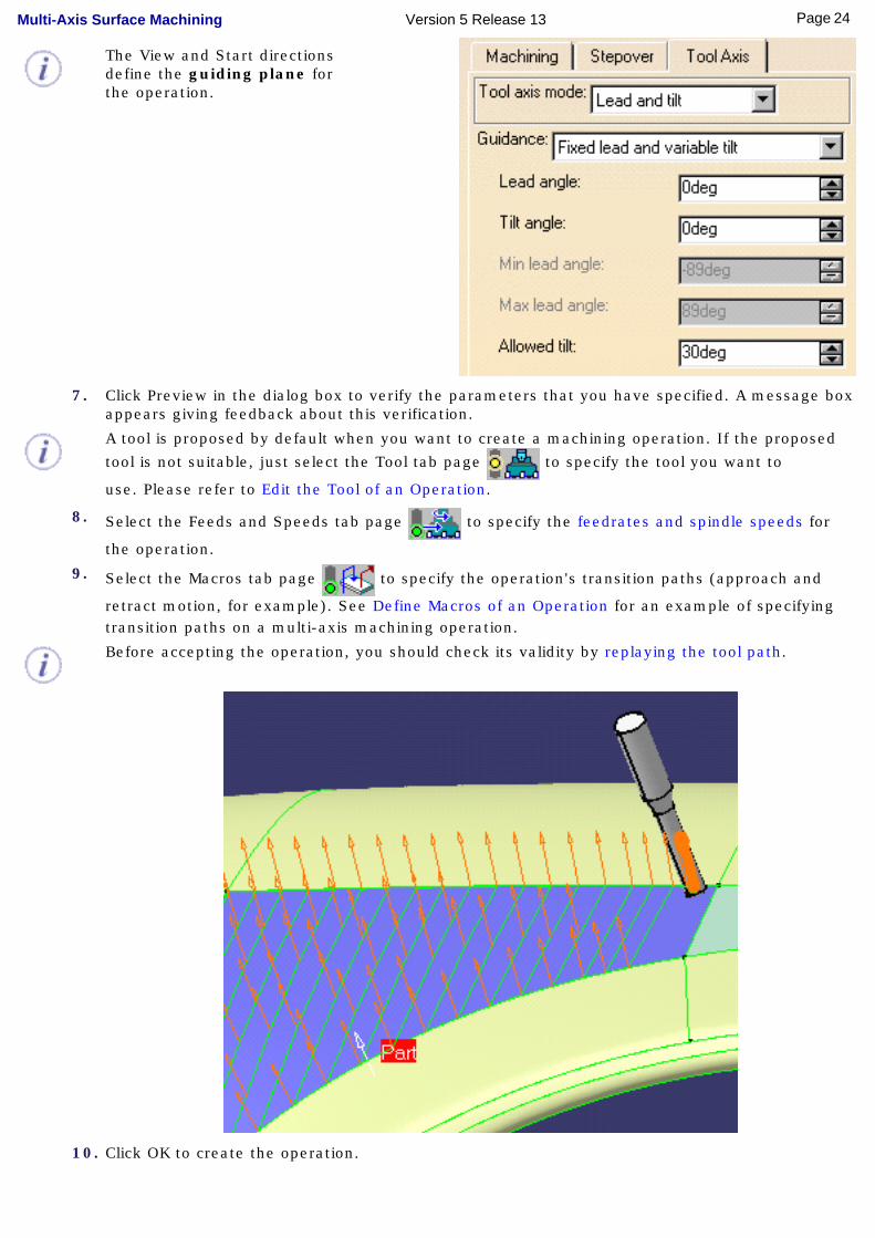
The View and Start directions define the guiding plane for the operation.
7. Click Preview in the dialog box to verify the parameters that you have specified. A message box appears giving feedback about this verification.
A tool is proposed by default when you want to create a machining operation. If the proposed
tool is not suitable, just select the Tool tab page to specify the tool you want to
use. Please refer to Edit the Tool of an Operation.
8. Select the Feeds and Speeds tab page to specify the feedrates and spindle speeds for
the operation.
9. Select the Macros tab page to specify the operation's transition paths (approach and
retract motion, for example). See Define Macros of an Operation for an example of specifying transition paths on a multi-axis machining operation.
Before accepting the operation, you should check its validity by replaying the tool path.
10. Click OK to create the operation.
24Page Multi-Axis Surface Machining Version 5 Release 13

25Page Multi-Axis Surface Machining Version 5 Release 13
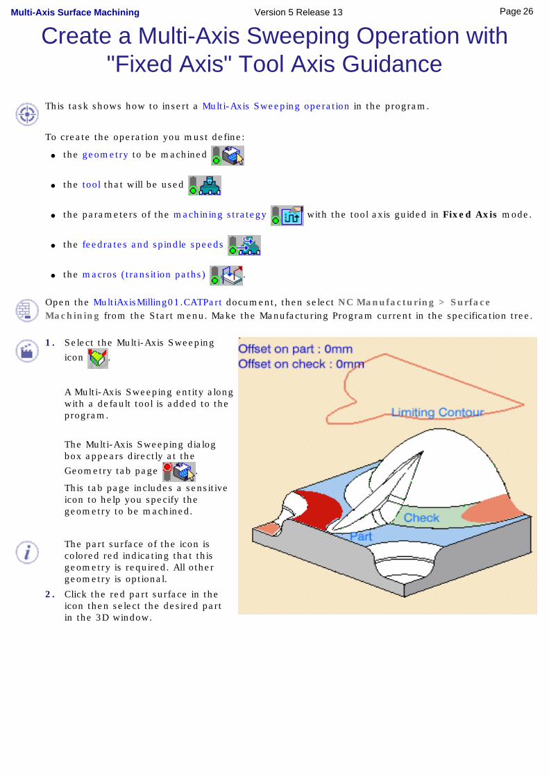
Create a Multi-Axis Sweeping Operation with "Fixed Axis" Tool Axis Guidance
This task shows how to insert a Multi-Axis Sweeping operation in the program.
To create the operation you must define:
● the geometry to be machined
● the tool that will be used
● the parameters of the machining strategy with the tool axis guided in Fixed Axis mode.
● the feedrates and spindle speeds
● the macros (transition paths) .
Open the MultiAxisMilling01.CATPart document, then select NC Manufacturing > Surface Machining from the Start menu. Make the Manufacturing Program current in the specification tree.
1. Select the Multi-Axis Sweeping
icon .
A Multi-Axis Sweeping entity along with a default tool is added to the program.
The Multi-Axis Sweeping dialog box appears directly at the
Geometry tab page .
This tab page includes a sensitive icon to help you specify the geometry to be machined.
The part surface of the icon is colored red indicating that this geometry is required. All other geometry is optional.
2. Click the red part surface in the icon then select the desired part in the 3D window.
26Page Multi-Axis Surface Machining Version 5 Release 13

3. Select the Strategy tab page
to specify parameters for:
● Machining
● Stepover
● Tool axis guidance (set it to Fixed Axis).
4. Click the Tool Axis arrow (A) and select the part surface. The surface normal is used as the tool axis.
5. Click the View Direction arrow (V) and select the part surface. The surface normal is used as the view direction.
Click the Start Direction arrow (S) and set this direction to (0,0,1) in the dialog box that appears.
A tool is proposed by default when you want to create a machining operation. If the proposed
tool is not suitable, just select the Tool tab page to specify the tool you want to use.
This is described in Edit the Tool of an Operation.
6. Select the Feeds and Speeds tab page to specify the feedrates and spindle speeds for
the operation.
7. Select the Macros tab page to specify the operation's transition paths (approach and
retract motion, for example).
See Define Macros of an Operation for an example of specifying transition paths on a multi-axis machining operation.
Before accepting the operation, you should check its validity by replaying the tool path.
8. Click OK to create the operation.
27Page Multi-Axis Surface Machining Version 5 Release 13
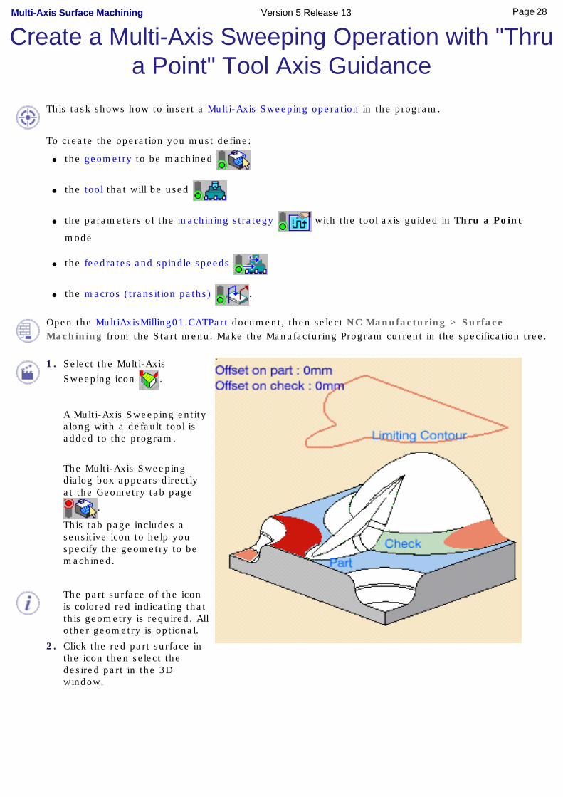
Create a Multi-Axis Sweeping Operation with "Thru a Point" Tool Axis Guidance
This task shows how to insert a Multi-Axis Sweeping operation in the program.
To create the operation you must define:
● the geometry to be machined
● the tool that will be used
● the parameters of the machining strategy with the tool axis guided in Thru a Point
mode
● the feedrates and spindle speeds
● the macros (transition paths) .
Open the MultiAxisMilling01.CATPart document, then select NC Manufacturing > Surface Machining from the Start menu. Make the Manufacturing Program current in the specification tree.
1. Select the Multi-Axis
Sweeping icon .
A Multi-Axis Sweeping entity along with a default tool is added to the program.
The Multi-Axis Sweeping dialog box appears directly at the Geometry tab page
.
This tab page includes a sensitive icon to help you specify the geometry to be machined.
The part surface of the icon is colored red indicating that this geometry is required. All other geometry is optional.
2. Click the red part surface in the icon then select the desired part in the 3D window.
28Page Multi-Axis Surface Machining Version 5 Release 13
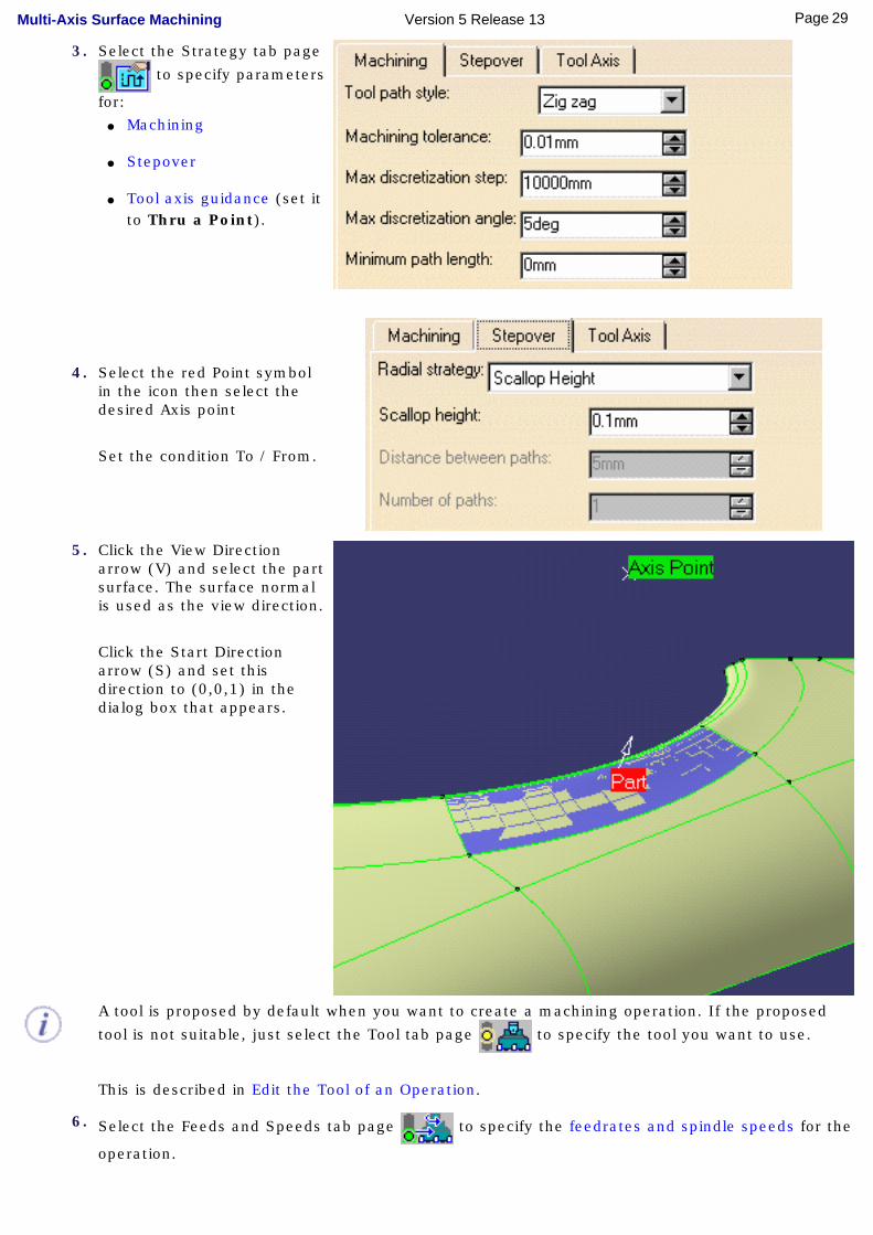
3. Select the Strategy tab page
to specify parameters
for: ● Machining
● Stepover
● Tool axis guidance (set it to Thru a Point).
4. Select the red Point symbol in the icon then select the desired Axis point
Set the condition To / From.
5. Click the View Direction arrow (V) and select the part surface. The surface normal is used as the view direction.
Click the Start Direction arrow (S) and set this direction to (0,0,1) in the dialog box that appears.
A tool is proposed by default when you want to create a machining operation. If the proposed
tool is not suitable, just select the Tool tab page to specify the tool you want to use.
This is described in Edit the Tool of an Operation.
6. Select the Feeds and Speeds tab page to specify the feedrates and spindle speeds for the
operation.
29Page Multi-Axis Surface Machining Version 5 Release 13
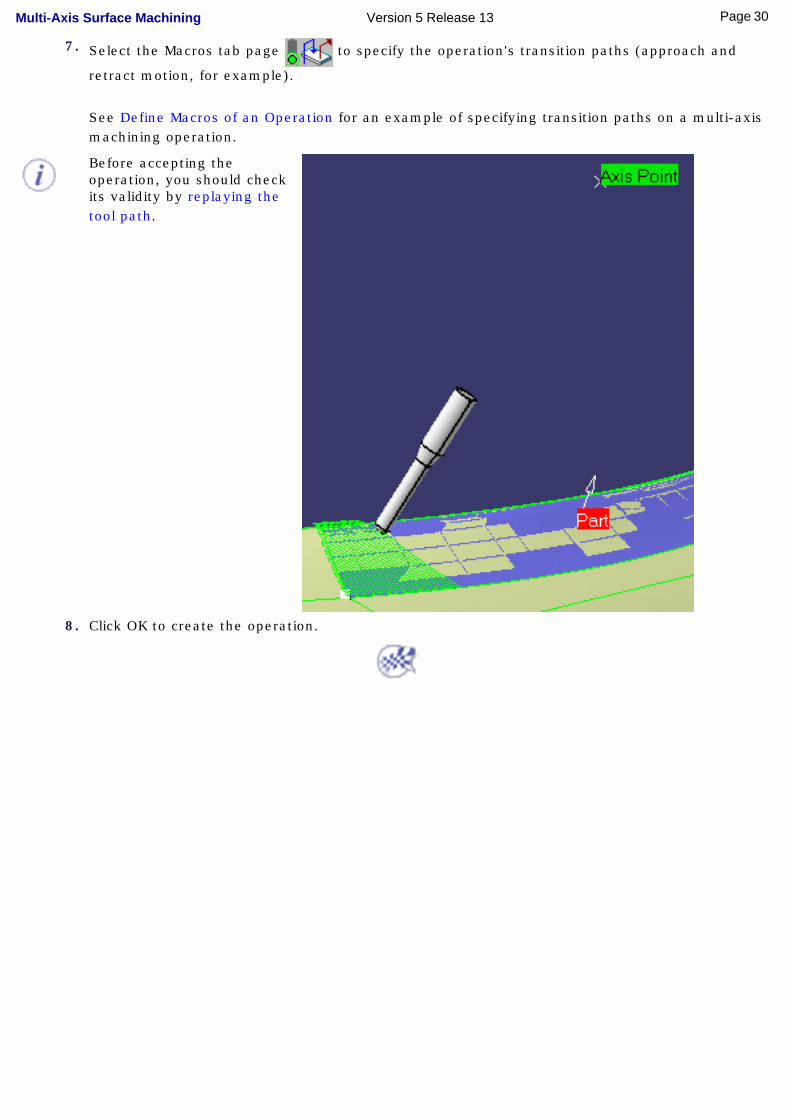
7. Select the Macros tab page to specify the operation's transition paths (approach and
retract motion, for example).
See Define Macros of an Operation for an example of specifying transition paths on a multi-axis machining operation.
Before accepting the operation, you should check its validity by replaying the tool path.
8. Click OK to create the operation.
30Page Multi-Axis Surface Machining Version 5 Release 13

Create a Multi-Axis Sweeping Operation with "Normal to Line" Tool Axis Guidance
This task shows how to insert a Multi-Axis Sweeping operation in the program.
To create the operation you must define:
● the geometry to be machined
● the tool that will be used
● the parameters of the machining strategy with the tool axis guided in Normal to Line
mode
● the feedrates and spindle speeds
● the macros (transition paths) .
Open the MultiAxisMilling01.CATPart document, then select NC Manufacturing > Surface Machining from the Start menu. Make the Manufacturing Program current in the specification tree.
1. Select the Multi-Axis Sweeping
icon .
A Multi-Axis Sweeping entity along with a default tool is added to the program.
The Multi-Axis Sweeping dialog box appears directly at the
Geometry tab page .
This tab page includes a sensitive icon to help you specify the geometry to be machined.
The part surface of the icon is colored red indicating that this geometry is required. All other geometry is optional.
2. Click the red part surface in the icon then select the desired part in the 3D window.
31Page Multi-Axis Surface Machining Version 5 Release 13

3. Select the Strategy tab page
to specify parameters for:
● Machining
● Stepover
● Tool axis guidance (set it to Normal to Line.
4. Select the red Line symbol in the icon then select the desired Axis line.
Set the condition To / From.
5. Click the View Direction arrow (V) and select the part surface. The surface normal is used as the view direction.
Click the Start Direction arrow (S) and set this direction to (0,0,1) in the dialog box that appears.
32Page Multi-Axis Surface Machining Version 5 Release 13

A tool is proposed by default when you want to create a machining operation. If the proposed
tool is not suitable, just select the Tool tab page to specify the tool you want to use.
This is described in Edit the Tool of an Operation.
6. Select the Feeds and Speeds tab page to specify the feedrates and spindle speeds for
the operation.
7. Select the Macros tab page to specify the operation's transition paths (approach and
retract motion, for example).
See Define Macros of an Operation for an example of specifying transition paths on a multi-axis machining operation.
Before accepting the operation, you should check its validity by replaying the tool path.
8. Click OK to create the operation.
33Page Multi-Axis Surface Machining Version 5 Release 13

Create a Multi-Axis Sweeping Operation with "4-Axis Lead/Lag" Tool Axis Guidance
This task illustrates how to create a Multi-Axis Sweeping operation in the program.
To create the operation you must define:
● the geometry to be machined
● the tool that will be used
● the parameters of the machining strategy with the tool axis guided in 4-Axis Lead/Lag
mode
● the feedrates and spindle speeds
● the macros (transition paths) .
Open the MultiAxisMilling01.CATPart document, then select NC Manufacturing > Surface Machining from the Start menu. Make the Manufacturing Program current in the specification tree.
1. Select the Multi-Axis Sweeping
icon .
A Multi-Axis Sweeping entity along with a default tool is added to the program.
The Multi-Axis Sweeping dialog box appears directly at the
Geometry tab page .
This tab page includes a sensitive icon to help you specify the geometry to be machined.
The part surface of the icon is colored red indicating that this geometry is required. All other geometry is optional.
2. Click the red part surface in the icon then select the desired part in the 3D window.
The part surface of the icon is now colored green indicating that this geometry is now defined.
34Page Multi-Axis Surface Machining Version 5 Release 13
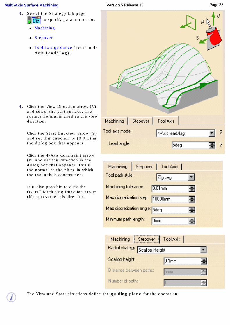
3. Select the Strategy tab page
to specify parameters for:
● Machining
● Stepover
● Tool axis guidance (set it to 4-Axis Lead/Lag).
4. Click the View Direction arrow (V) and select the part surface. The surface normal is used as the view direction.
Click the Start Direction arrow (S) and set this direction to (0,0,1) in the dialog box that appears.
Click the 4-Axis Constraint arrow (N) and set this direction in the dialog box that appears. This is the normal to the plane in which the tool axis is constrained.
It is also possible to click the Overall Machining Direction arrow (M) to reverse this direction.
The View and Start directions define the guiding plane for the operation.
35Page Multi-Axis Surface Machining Version 5 Release 13
5. Click Preview in the dialog box to verify the parameters that you have specified.
A message box appears giving feedback about this verification.
A tool is proposed by default when you want to create a machining operation. If the proposed
tool is not suitable, just select the Tool tab page to specify the tool you want to use.
Please refer to Edit the Tool of an Operation.
6. Select the Feeds and Speeds tab page to specify the feedrates and spindle speeds for
the operation.
7. Select the Macros tab page to specify the operation's transition paths (approach and
retract motion, for example).
See Define Macros of an Operation for an example of specifying transition paths on a multi-axis machining operation.
Before accepting the operation, you should check its validity by replaying the tool path.
8. Click OK to create the operation.
36Page Multi-Axis Surface Machining Version 5 Release 13
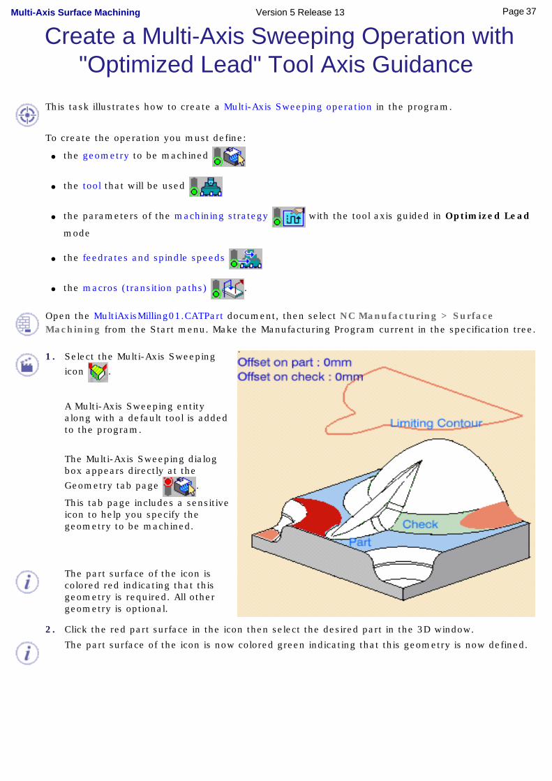
Create a Multi-Axis Sweeping Operation with "Optimized Lead" Tool Axis Guidance
This task illustrates how to create a Multi-Axis Sweeping operation in the program.
To create the operation you must define:
● the geometry to be machined
● the tool that will be used
● the parameters of the machining strategy with the tool axis guided in Optimized Lead
mode
● the feedrates and spindle speeds
● the macros (transition paths) .
Open the MultiAxisMilling01.CATPart document, then select NC Manufacturing > Surface Machining from the Start menu. Make the Manufacturing Program current in the specification tree.
1. Select the Multi-Axis Sweeping
icon .
A Multi-Axis Sweeping entity along with a default tool is added to the program.
The Multi-Axis Sweeping dialog box appears directly at the
Geometry tab page .
This tab page includes a sensitive icon to help you specify the geometry to be machined.
The part surface of the icon is colored red indicating that this geometry is required. All other geometry is optional.
2. Click the red part surface in the icon then select the desired part in the 3D window.
The part surface of the icon is now colored green indicating that this geometry is now defined.
37Page Multi-Axis Surface Machining Version 5 Release 13
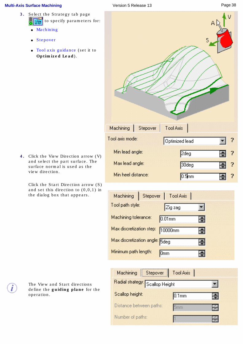
3. Select the Strategy tab page
to specify parameters for:
● Machining
● Stepover
● Tool axis guidance (set it to Optimized Lead).
4. Click the View Direction arrow (V) and select the part surface. The surface normal is used as the view direction.
Click the Start Direction arrow (S) and set this direction to (0,0,1) in the dialog box that appears.
The View and Start directions define the guiding plane for the operation.
38Page Multi-Axis Surface Machining Version 5 Release 13
5. Click Preview in the dialog box to verify the parameters that you have specified.
A message box appears giving feedback about this verification.
A tool is proposed by default when you want to create a machining operation. If the proposed
tool is not suitable, just select the Tool tab page to specify the tool you want to use.
Please refer to Edit the Tool of an Operation.
6. Select the Feeds and Speeds tab page to specify the feedrates and spindle speeds for
the operation.
7. Select the Macros tab page to specify the operation's transition paths (approach and
retract motion, for example).
See Define Macros of an Operation for an example of specifying transition paths on a multi-axis machining operation.
Before accepting the operation, you should check its validity by replaying the tool path.
8. Click OK to create the operation.
39Page Multi-Axis Surface Machining Version 5 Release 13
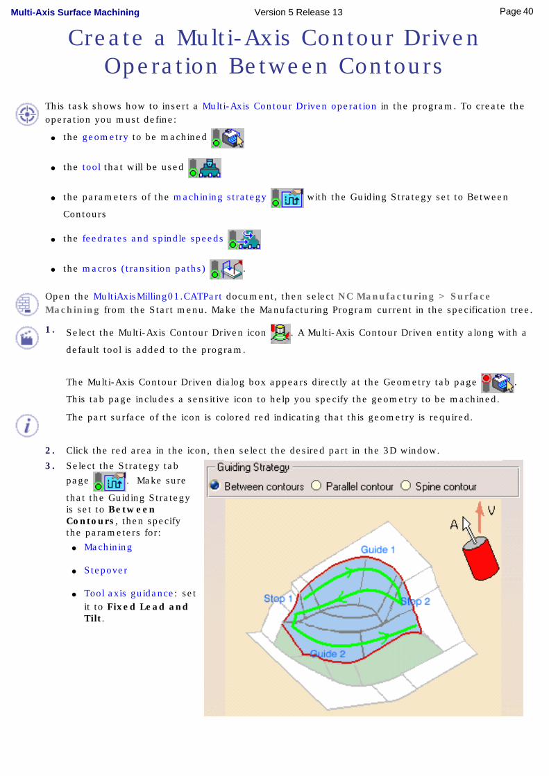
Create a Multi-Axis Contour Driven Operation Between Contours
This task shows how to insert a Multi-Axis Contour Driven operation in the program. To create the operation you must define:
● the geometry to be machined
● the tool that will be used
● the parameters of the machining strategy with the Guiding Strategy set to Between
Contours
● the feedrates and spindle speeds
● the macros (transition paths) .
Open the MultiAxisMilling01.CATPart document, then select NC Manufacturing > Surface Machining from the Start menu. Make the Manufacturing Program current in the specification tree.
1. Select the Multi-Axis Contour Driven icon . A Multi-Axis Contour Driven entity along with a
default tool is added to the program.
The Multi-Axis Contour Driven dialog box appears directly at the Geometry tab page .
This tab page includes a sensitive icon to help you specify the geometry to be machined.
The part surface of the icon is colored red indicating that this geometry is required.
2. Click the red area in the icon, then select the desired part in the 3D window.
3. Select the Strategy tab
page . Make sure
that the Guiding Strategy is set to Between Contours, then specify the parameters for:
● Machining
● Stepover
● Tool axis guidance: set it to Fixed Lead and Tilt.
40Page Multi-Axis Surface Machining Version 5 Release 13
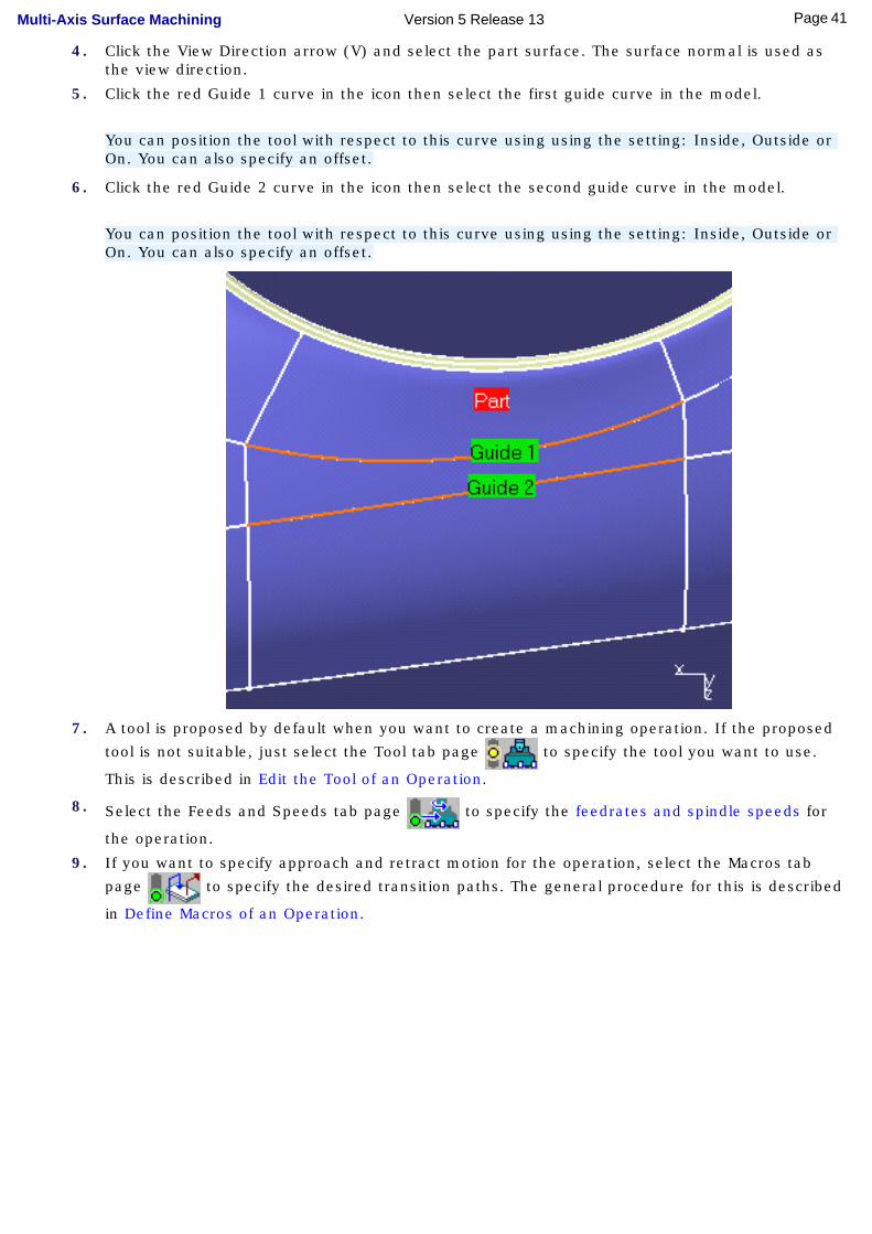
4. Click the View Direction arrow (V) and select the part surface. The surface normal is used as the view direction.
5. Click the red Guide 1 curve in the icon then select the first guide curve in the model.
You can position the tool with respect to this curve using using the setting: Inside, Outside or On. You can also specify an offset.
6. Click the red Guide 2 curve in the icon then select the second guide curve in the model.
You can position the tool with respect to this curve using using the setting: Inside, Outside or On. You can also specify an offset.
7. A tool is proposed by default when you want to create a machining operation. If the proposed
tool is not suitable, just select the Tool tab page to specify the tool you want to use.
This is described in Edit the Tool of an Operation.
8. Select the Feeds and Speeds tab page to specify the feedrates and spindle speeds for
the operation.
9. If you want to specify approach and retract motion for the operation, select the Macros tab
page to specify the desired transition paths. The general procedure for this is described
in Define Macros of an Operation.
41Page Multi-Axis Surface Machining Version 5 Release 13
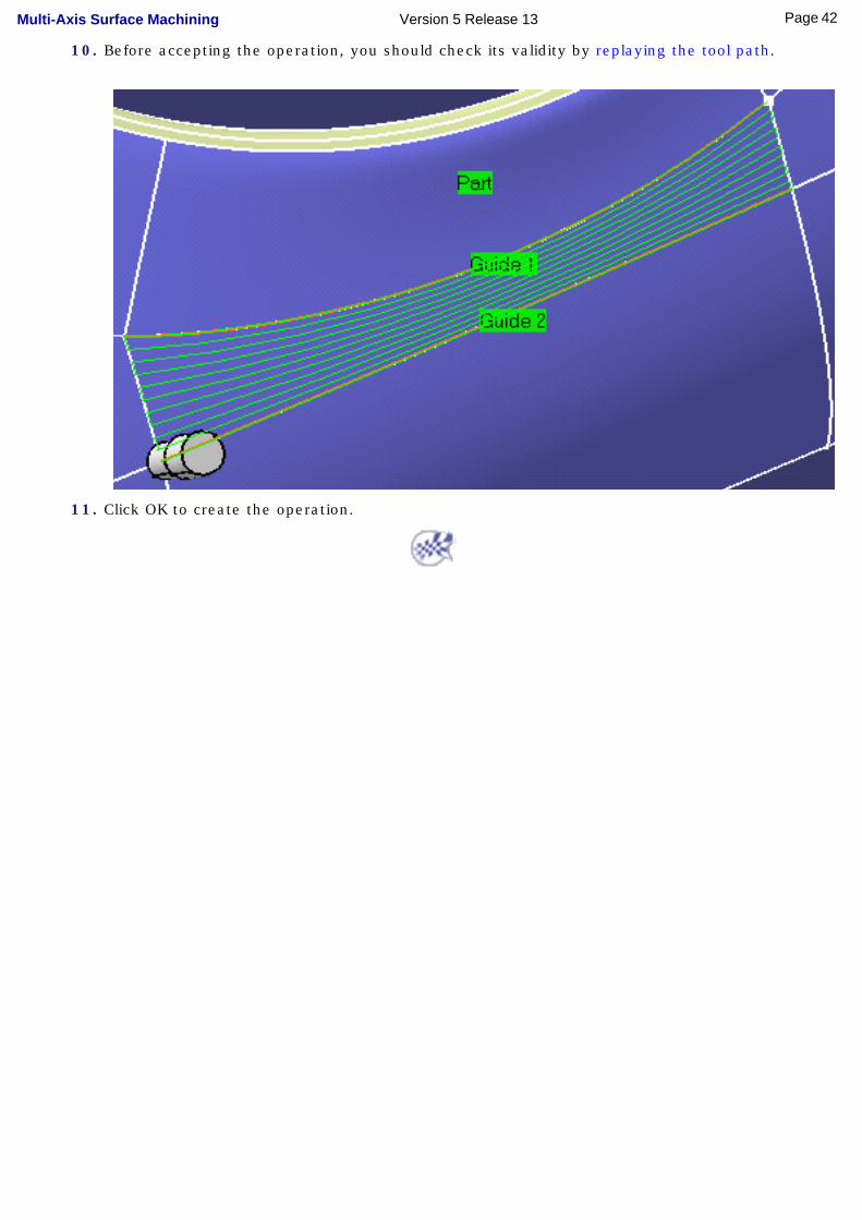
10. Before accepting the operation, you should check its validity by replaying the tool path.
11. Click OK to create the operation.
42Page Multi-Axis Surface Machining Version 5 Release 13

Create a Multi-Axis Contour Driven Operation with Parallel Contours
This task shows how to insert a 'Parallel Contour' Multi-Axis Contour Driven operation in the program.
To create the operation you must define:
● the geometry to be machined
● the tool that will be used
● the parameters of the machining strategy with the Guiding Strategy set to Parallel
Contour
● the feedrates and spindle speeds
● the macros (transition paths) .
Open the MultiAxisMilling01.CATPart document, then select NC Manufacturing > Surface Machining from the Start menu. Make the Manufacturing Program current in the specification tree.
1. Select the Multi-Axis Contour Driven icon .
A Multi-Axis Contour Driven entity along with a default tool is added to the program.
The Multi-Axis Contour Driven dialog box appears directly at the Geometry tab page .
This tab page includes a sensitive icon to help you specify the geometry to be machined.
The part surface of the icon is colored red indicating that this geometry is required.
2. Click the red part surface in the icon then select the desired part in the 3D window.
3. Select the Strategy tab page
. Make sure that the
Guiding Strategy is set to Parallel Contour then specify the parameters for:
● Machining
● Stepover:Stepover Side to LeftMax width to machine to 75mm
● Tool axis guidance: Fixed Lead and Tilt.
43Page Multi-Axis Surface Machining Version 5 Release 13
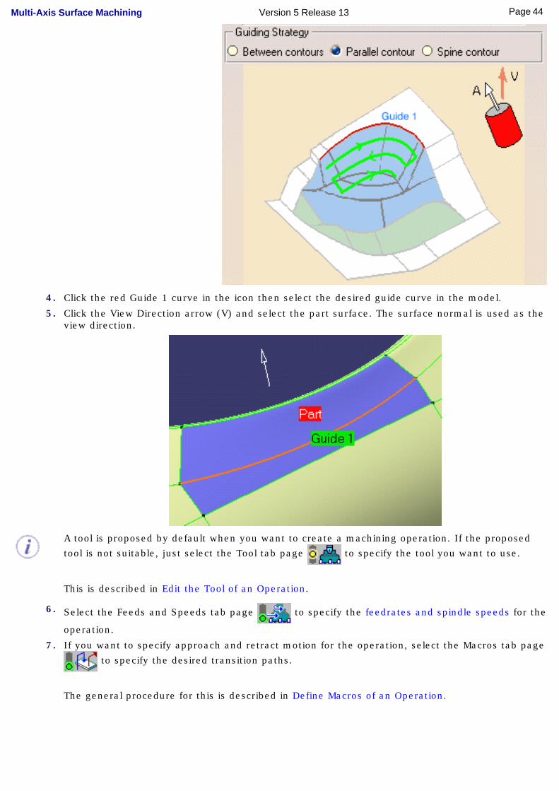
4. Click the red Guide 1 curve in the icon then select the desired guide curve in the model.
5. Click the View Direction arrow (V) and select the part surface. The surface normal is used as the view direction.
A tool is proposed by default when you want to create a machining operation. If the proposed
tool is not suitable, just select the Tool tab page to specify the tool you want to use.
This is described in Edit the Tool of an Operation.
6. Select the Feeds and Speeds tab page to specify the feedrates and spindle speeds for the
operation.
7. If you want to specify approach and retract motion for the operation, select the Macros tab page
to specify the desired transition paths.
The general procedure for this is described in Define Macros of an Operation.
44Page Multi-Axis Surface Machining Version 5 Release 13
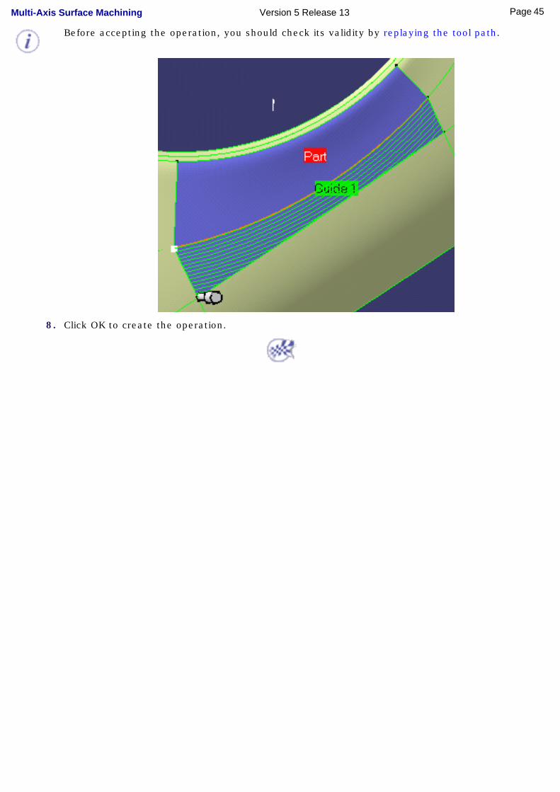
Before accepting the operation, you should check its validity by replaying the tool path.
8. Click OK to create the operation.
45Page Multi-Axis Surface Machining Version 5 Release 13
Create a Multi-Axis Contour Driven Operation with Spine Contour
This task shows how to insert a 'Spine Contour' Multi-Axis Contour Driven operation in the program.
To create the operation you must define:
● the geometry of the pocket to be machined
● the tool that will be used
● the parameters of the machining strategy with the Guiding Strategy set to Spine Contour
● the feedrates and spindle speeds
● the macros (transition paths) .
Open the MultiAxisMilling01.CATPart document, then select NC Manufacturing > Surface Machining from the Start menu. Make the Manufacturing Program current in the specification tree.
1. Select the Multi-Axis Contour Driven icon .
A Multi-Axis Contour Driven entity along with a default tool is added to the program.
The Multi-Axis Contour Driven dialog box appears directly at the Geometry tab page .
This tab page includes a sensitive icon to help you specify the geometry to be machined.
The part surface of the icon is colored red indicating that this geometry is required.
2. Click the red area in the icon then select the desired part surface in the 3D window.
3. Select the Strategy tab page
. Make sure that the
Guiding Strategy is set to Spine Contour then specify the parameters for:
● Machining
● Stepover
● Tool axis guidance: Fixed Lead and Tilt.
46Page Multi-Axis Surface Machining Version 5 Release 13
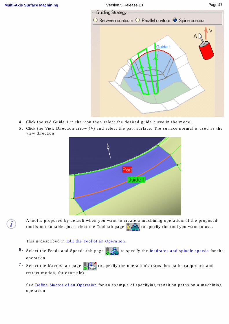
4. Click the red Guide 1 in the icon then select the desired guide curve in the model.
5. Click the View Direction arrow (V) and select the part surface. The surface normal is used as the view direction.
A tool is proposed by default when you want to create a machining operation. If the proposed
tool is not suitable, just select the Tool tab page to specify the tool you want to use.
This is described in Edit the Tool of an Operation.
6. Select the Feeds and Speeds tab page to specify the feedrates and spindle speeds for the
operation.
7. Select the Macros tab page to specify the operation's transition paths (approach and
retract motion, for example).
See Define Macros of an Operation for an example of specifying transition paths on a machining operation.
47Page Multi-Axis Surface Machining Version 5 Release 13
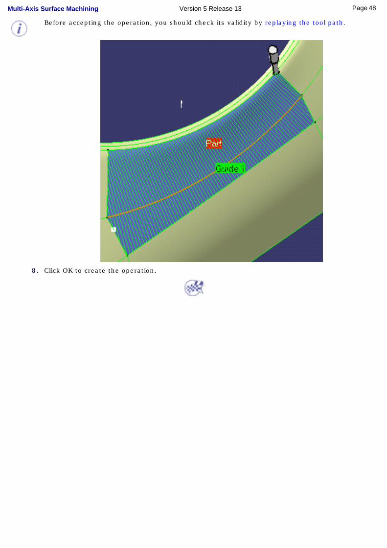
Before accepting the operation, you should check its validity by replaying the tool path.
8. Click OK to create the operation.
48Page Multi-Axis Surface Machining Version 5 Release 13

Create a Multi-Axis Contact CurveMachining Operation
This task shows how to insert a 'Contact' Curve Machining operation in the program. To create the operation you must define:
● the Curve Machining mode as Contact
● the geometry to be machined
● the tool that will be used
● the parameters of the machining strategy with the tool axis guided in Lead and Tilt mode
● the feedrates and spindle speeds
● the macros (transition paths) .
Open the MultiAxisMilling01.CATPart document, then select NC Manufacturing > Surface Machining from the Start menu. Make the Manufacturing Program current in the specification tree.
1. Select the Multi-Axis Curve
Machining icon .
The Multi-Axis Curve Machining dialog box appears directly at the Geometry tab page
.
This page includes a sensitive icon to help you specify the geometry to be machined.
Set the Curve Machining mode to Contact to drive the contact point.
The part and guide curve in the icon are colored red indicating that this geometry is required for defining the operation. All other geometry is optional.
2. Click the red part in the icon, then select the four faces in the 3D window as shown in the figure below.
3. Click the red guide element in the icon, then select four edges in the 3D window as shown in the figure below. You will be prompted to insert a line in the gap between the third and forth edge in order to keep the curve continuous.
49Page Multi-Axis Surface Machining Version 5 Release 13
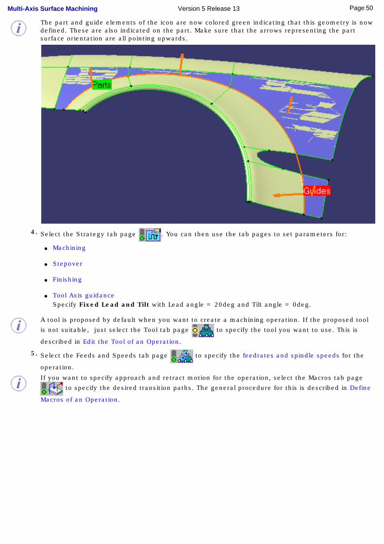
The part and guide elements of the icon are now colored green indicating that this geometry is now defined. These are also indicated on the part. Make sure that the arrows representing the part surface orientation are all pointing upwards.
4. Select the Strategy tab page . You can then use the tab pages to set parameters for:
● Machining
● Stepover
● Finishing
● Tool Axis guidance Specify Fixed Lead and Tilt with Lead angle = 20deg and Tilt angle = 0deg.
A tool is proposed by default when you want to create a machining operation. If the proposed tool
is not suitable, just select the Tool tab page to specify the tool you want to use. This is
described in Edit the Tool of an Operation.
5. Select the Feeds and Speeds tab page to specify the feedrates and spindle speeds for the
operation.
If you want to specify approach and retract motion for the operation, select the Macros tab page
to specify the desired transition paths. The general procedure for this is described in Define
Macros of an Operation.
50Page Multi-Axis Surface Machining Version 5 Release 13
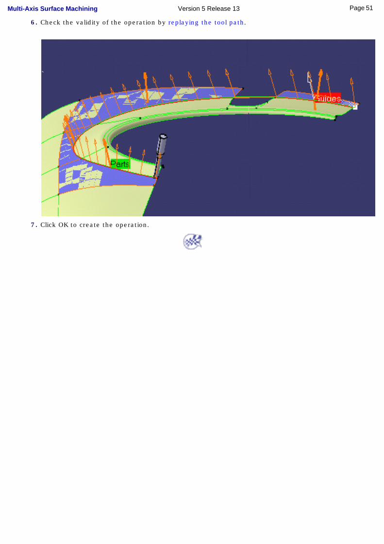
6. Check the validity of the operation by replaying the tool path.
7. Click OK to create the operation.
51Page Multi-Axis Surface Machining Version 5 Release 13
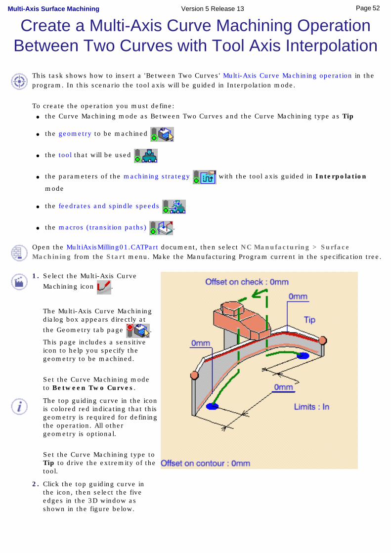
Create a Multi-Axis Curve Machining Operation Between Two Curves with Tool Axis Interpolation
This task shows how to insert a 'Between Two Curves' Multi-Axis Curve Machining operation in the program. In this scenario the tool axis will be guided in Interpolation mode.
To create the operation you must define: ● the Curve Machining mode as Between Two Curves and the Curve Machining type as Tip
● the geometry to be machined
● the tool that will be used
● the parameters of the machining strategy with the tool axis guided in Interpolation
mode
● the feedrates and spindle speeds
● the macros (transition paths) .
Open the MultiAxisMilling01.CATPart document, then select NC Manufacturing > Surface Machining from the Start menu. Make the Manufacturing Program current in the specification tree.
1. Select the Multi-Axis Curve
Machining icon .
The Multi-Axis Curve Machining dialog box appears directly at
the Geometry tab page .
This page includes a sensitive icon to help you specify the geometry to be machined.
Set the Curve Machining mode to Between Two Curves.
The top guiding curve in the icon is colored red indicating that this geometry is required for defining the operation. All other geometry is optional.
Set the Curve Machining type to Tip to drive the extremity of the tool.
2. Click the top guiding curve in the icon, then select the five edges in the 3D window as shown in the figure below.
52Page Multi-Axis Surface Machining Version 5 Release 13
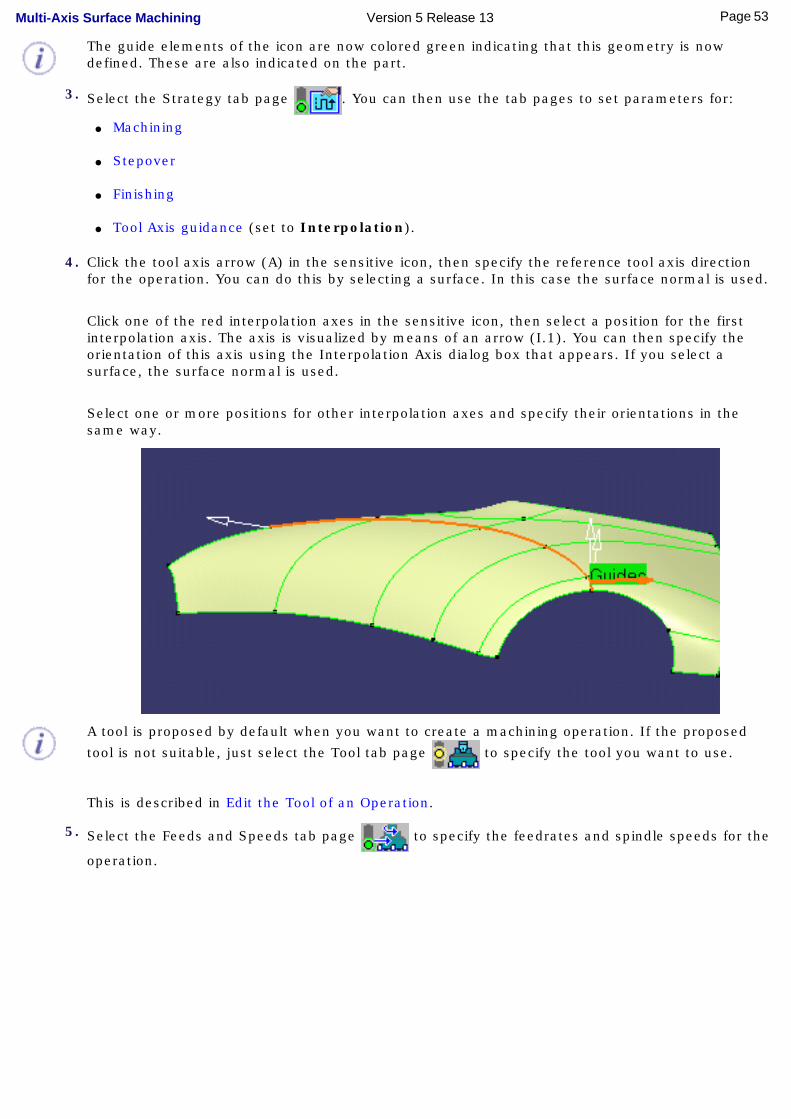
The guide elements of the icon are now colored green indicating that this geometry is now defined. These are also indicated on the part.
3. Select the Strategy tab page . You can then use the tab pages to set parameters for:
● Machining
● Stepover
● Finishing
● Tool Axis guidance (set to Interpolation).
4. Click the tool axis arrow (A) in the sensitive icon, then specify the reference tool axis direction for the operation. You can do this by selecting a surface. In this case the surface normal is used.
Click one of the red interpolation axes in the sensitive icon, then select a position for the first interpolation axis. The axis is visualized by means of an arrow (I.1). You can then specify the orientation of this axis using the Interpolation Axis dialog box that appears. If you select a surface, the surface normal is used.
Select one or more positions for other interpolation axes and specify their orientations in the same way.
A tool is proposed by default when you want to create a machining operation. If the proposed
tool is not suitable, just select the Tool tab page to specify the tool you want to use.
This is described in Edit the Tool of an Operation.
5. Select the Feeds and Speeds tab page to specify the feedrates and spindle speeds for the
operation.
53Page Multi-Axis Surface Machining Version 5 Release 13
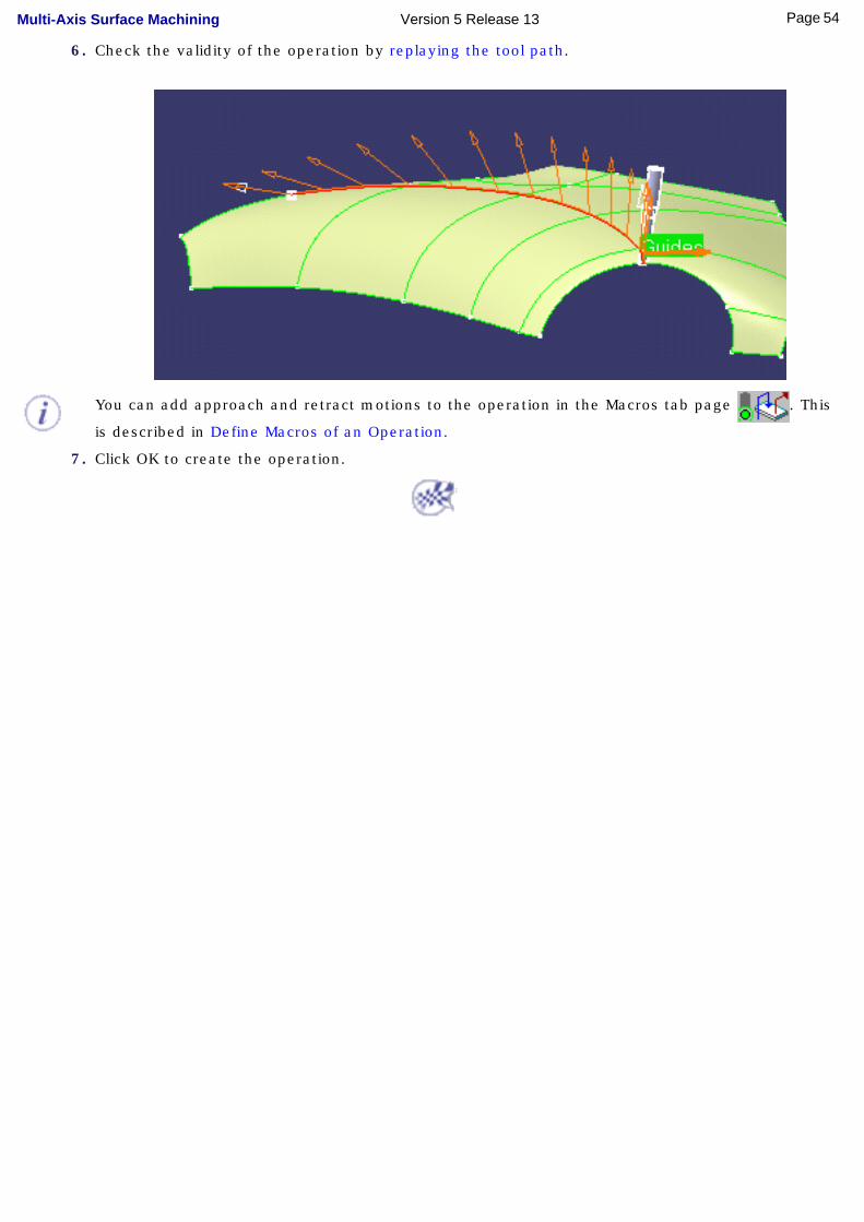
6. Check the validity of the operation by replaying the tool path.
You can add approach and retract motions to the operation in the Macros tab page . This
is described in Define Macros of an Operation.
7. Click OK to create the operation.
54Page Multi-Axis Surface Machining Version 5 Release 13
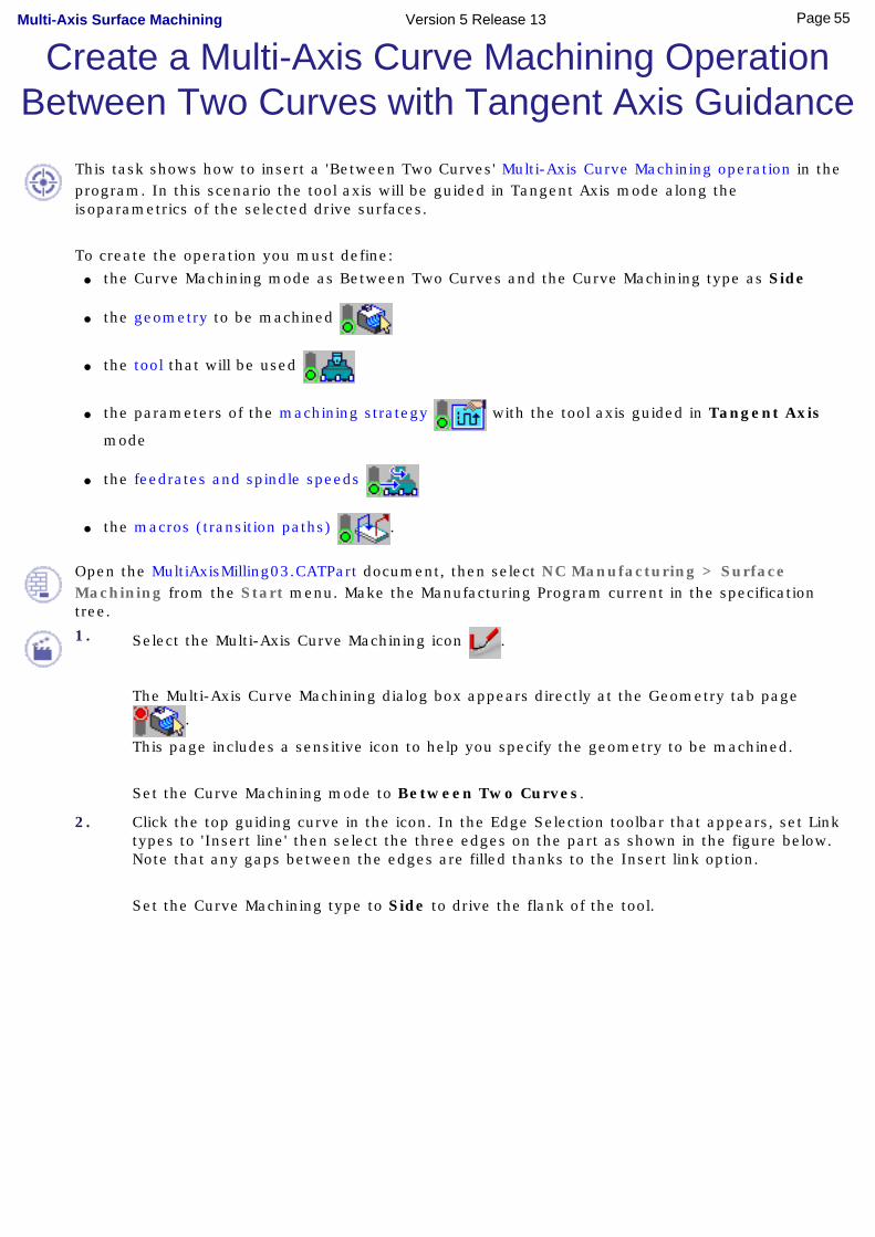
Create a Multi-Axis Curve Machining Operation Between Two Curves with Tangent Axis Guidance
This task shows how to insert a 'Between Two Curves' Multi-Axis Curve Machining operation in the program. In this scenario the tool axis will be guided in Tangent Axis mode along the isoparametrics of the selected drive surfaces.
To create the operation you must define: ● the Curve Machining mode as Between Two Curves and the Curve Machining type as Side
● the geometry to be machined
● the tool that will be used
● the parameters of the machining strategy with the tool axis guided in Tangent Axis
mode
● the feedrates and spindle speeds
● the macros (transition paths) .
Open the MultiAxisMilling03.CATPart document, then select NC Manufacturing > Surface Machining from the Start menu. Make the Manufacturing Program current in the specification tree.
1. Select the Multi-Axis Curve Machining icon .
The Multi-Axis Curve Machining dialog box appears directly at the Geometry tab page
.
This page includes a sensitive icon to help you specify the geometry to be machined.
Set the Curve Machining mode to Between Two Curves.
2. Click the top guiding curve in the icon. In the Edge Selection toolbar that appears, set Link types to 'Insert line' then select the three edges on the part as shown in the figure below. Note that any gaps between the edges are filled thanks to the Insert link option.
Set the Curve Machining type to Side to drive the flank of the tool.
55Page Multi-Axis Surface Machining Version 5 Release 13

3. Select the Strategy tab page . This
page includes a sensitive icon to help you specify the drive surfaces and reference tool axis.
Click the sensitive drive element in the icon, then select the three drive surfaces in the 3D window as shown in the figure.
You can then use the tab pages to set parameters for:
● Machining
● Stepover
● Finishing
● Tool Axis guidance (set to Tangent Axis - Along isoparametric lines).
A default reference tool axis is displayed in the 3D view. If needed, you can modify it by clicking the tool axis arrow (A) in the sensitive icon, then specifying a different tool axis direction. You can do this by selecting a surface. In this case the surface normal is used.
When machining a strip (or band) for faces, the tool axis is deduced from the isoparametrics of the faces in order to ensure continuity of the trajectory. See Tangent Axis - Along isoparametric lines for more information.
4. A tool is proposed by default when you want to create a machining operation. If the
proposed tool is not suitable, just select the Tool tab page to specify the tool you
want to use.
This is described in Edit the Tool of an Operation.
5. Select the Feeds and Speeds tab page to specify the feedrates and spindle speeds
for the operation.
56Page Multi-Axis Surface Machining Version 5 Release 13
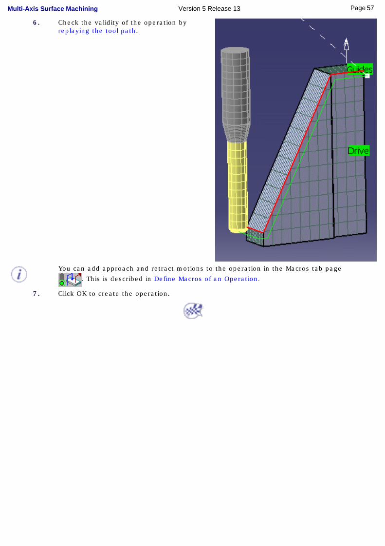
6. Check the validity of the operation by replaying the tool path.
You can add approach and retract motions to the operation in the Macros tab page
. This is described in Define Macros of an Operation.
7. Click OK to create the operation.
57Page Multi-Axis Surface Machining Version 5 Release 13

Create a Multi-Axis Curve Machining Operation Between a Curve and Part
This task shows how to insert a 'Between Curve and Part' Multi-Axis Curve Machining operation in the program.
To create the operation you must define: ● the Curve Machining mode as Between Curve and Part and the Curve Machining type to Side
● the geometry to be machined
● the tool that will be used
● the parameters of the machining strategy with the tool axis guided in Interpolation mode
● the feedrates and spindle speeds
● the macros (transition paths) .
Open the MultiAxisMilling01.CATPart document, then select NC Manufacturing > Surface Machining from the Start menu. Make the Manufacturing Program current in the specification tree.
1. Select the Multi-Axis Curve Machining icon
.
The Multi-Axis Curve Machining dialog box appears directly at the Geometry tab page
.
This page includes a sensitive icon to help you specify the geometry to be machined.
Set the Curve machining mode to Between Curve and Part.
The top guiding curve and part bottom in the icon are colored red indicating that this geometry is required for defining the operation. All other geometry is optional.
Set the Curve Machining type to Side to drive the tool flank.
2. Click the red bottom in the icon, then select the 6 faces in the 3D window as shown in the figure.
3. Click the top guiding curve in the icon, then select the 6 edges in the 3D window as shown in the figure.
The part and guide elements of the icon are now colored green indicating that this geometry is now defined. These are also indicated on the part.
4. Select the Strategy tab page . You can then use the tab pages to set parameters for:
● Machining
● Stepover (set Radial strategy with Distance between paths = 3mm and Number of paths = 4)
● Finishing
● Tool Axis guidance (set to Interpolation).
58Page Multi-Axis Surface Machining Version 5 Release 13
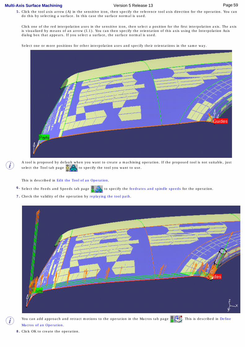
5. Click the tool axis arrow (A) in the sensitive icon, then specify the reference tool axis direction for the operation. You can do this by selecting a surface. In this case the surface normal is used.
Click one of the red interpolation axes in the sensitive icon, then select a position for the first interpolation axis. The axis is visualized by means of an arrow (I.1). You can then specify the orientation of this axis using the Interpolation Axis dialog box that appears. If you select a surface, the surface normal is used.
Select one or more positions for other interpolation axes and specify their orientations in the same way.
A tool is proposed by default when you want to create a machining operation. If the proposed tool is not suitable, just
select the Tool tab page to specify the tool you want to use.
This is described in Edit the Tool of an Operation.
6. Select the Feeds and Speeds tab page to specify the feedrates and spindle speeds for the operation.
7. Check the validity of the operation by replaying the tool path.
You can add approach and retract motions to the operation in the Macros tab page . This is described in Define
Macros of an Operation.
8. Click OK to create the operation.
59Page Multi-Axis Surface Machining Version 5 Release 13

60Page Multi-Axis Surface Machining Version 5 Release 13

Create a Multi-Axis Isoparametric Machining Operation with "Lead and Tilt" Tool Axis
Guidance
This task illustrates how to create a Multi-Axis Isoparametric Machining operation in the program. To create the operation you must define:
● the geometry to be machined
● the tool that will be used
● the parameters of the machining strategy with the tool axis guided in Lead and Tilt
mode
● the feedrates and spindle speeds
● the macros (transition paths) .
Open the MultiAxisMilling02.CATPart document, then select NC Manufacturing > Surface Machining from the Start menu. Make the Manufacturing Program current in the specification tree.
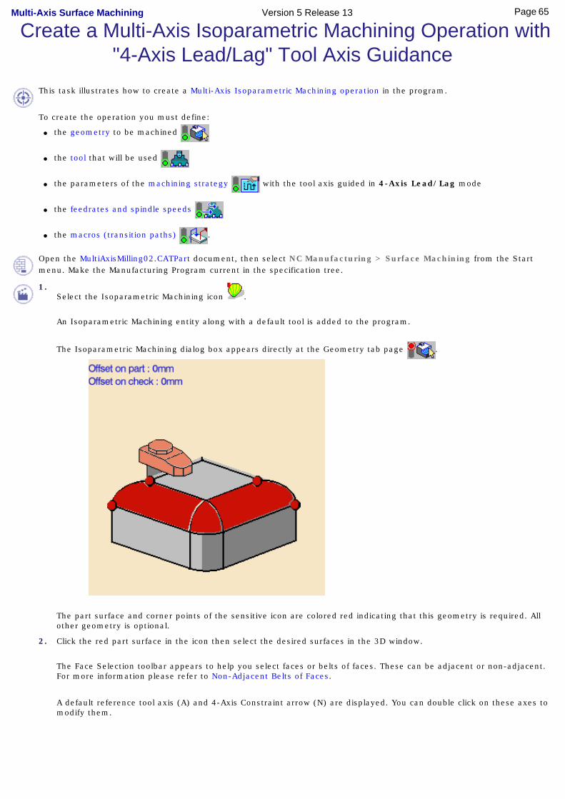
1. Select the Isoparametric Machining icon . An Isoparametric Machining entity along with a
default tool is added to the program. The Isoparametric Machining dialog box appears directly at
the Geometry tab page .
The part surface and corner points of the sensitive icon are colored red indicating that this geometry is required. All other geometry is optional.
61Page Multi-Axis Surface Machining Version 5 Release 13
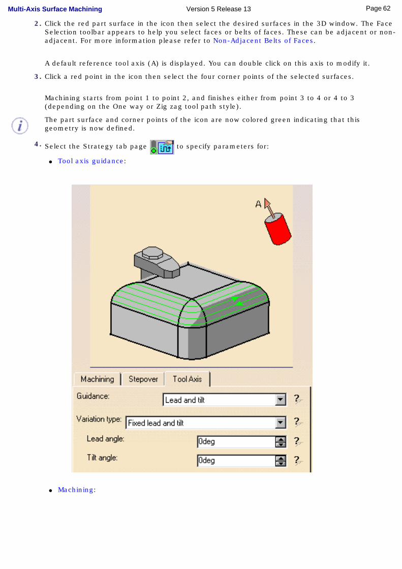
2. Click the red part surface in the icon then select the desired surfaces in the 3D window. The Face Selection toolbar appears to help you select faces or belts of faces. These can be adjacent or non-adjacent. For more information please refer to Non-Adjacent Belts of Faces.
A default reference tool axis (A) is displayed. You can double click on this axis to modify it.
3. Click a red point in the icon then select the four corner points of the selected surfaces.
Machining starts from point 1 to point 2, and finishes either from point 3 to 4 or 4 to 3 (depending on the One way or Zig zag tool path style).
The part surface and corner points of the icon are now colored green indicating that this geometry is now defined.
4. Select the Strategy tab page to specify parameters for:
● Tool axis guidance:
● Machining:
62Page Multi-Axis Surface Machining Version 5 Release 13
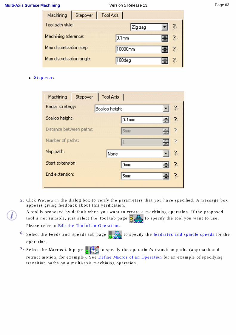
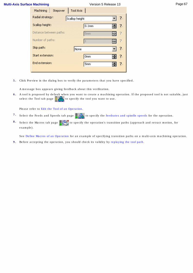
● Stepover:
5. Click Preview in the dialog box to verify the parameters that you have specified. A message box appears giving feedback about this verification.
A tool is proposed by default when you want to create a machining operation. If the proposed
tool is not suitable, just select the Tool tab page to specify the tool you want to use.
Please refer to Edit the Tool of an Operation.
6. Select the Feeds and Speeds tab page to specify the feedrates and spindle speeds for the
operation.
7. Select the Macros tab page to specify the operation's transition paths (approach and
retract motion, for example). See Define Macros of an Operation for an example of specifying transition paths on a multi-axis machining operation.
63Page Multi-Axis Surface Machining Version 5 Release 13

Before accepting the operation, you should check its validity by replaying the tool path.
8. Click OK to create the operation.
64Page Multi-Axis Surface Machining Version 5 Release 13
Create a Multi-Axis Isoparametric Machining Operation with "4-Axis Lead/Lag" Tool Axis Guidance
This task illustrates how to create a Multi-Axis Isoparametric Machining operation in the program.
To create the operation you must define:
● the geometry to be machined
● the tool that will be used
● the parameters of the machining strategy with the tool axis guided in 4-Axis Lead/Lag mode
● the feedrates and spindle speeds
● the macros (transition paths) .
Open the MultiAxisMilling02.CATPart document, then select NC Manufacturing > Surface Machining from the Start menu. Make the Manufacturing Program current in the specification tree.
1.Select the Isoparametric Machining icon .
An Isoparametric Machining entity along with a default tool is added to the program.
The Isoparametric Machining dialog box appears directly at the Geometry tab page .
The part surface and corner points of the sensitive icon are colored red indicating that this geometry is required. All other geometry is optional.
2. Click the red part surface in the icon then select the desired surfaces in the 3D window.
The Face Selection toolbar appears to help you select faces or belts of faces. These can be adjacent or non-adjacent. For more information please refer to Non-Adjacent Belts of Faces.
A default reference tool axis (A) and 4-Axis Constraint arrow (N) are displayed. You can double click on these axes to modify them.
65Page Multi-Axis Surface Machining Version 5 Release 13
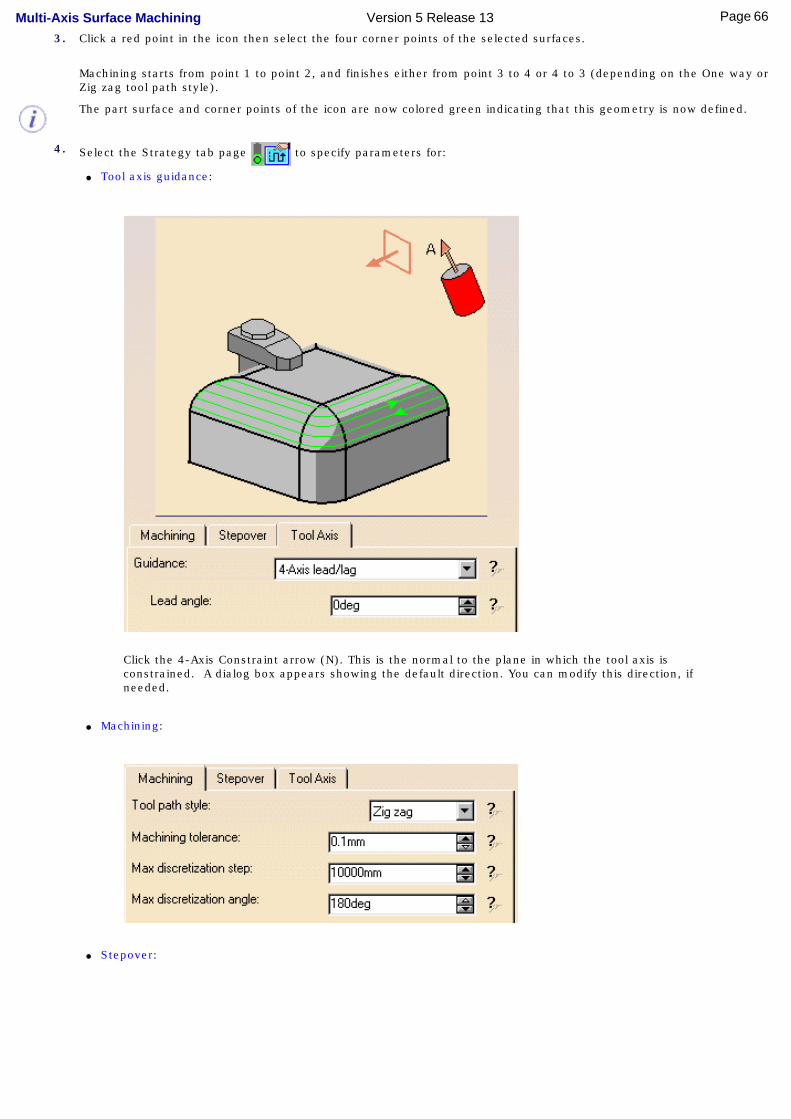
3. Click a red point in the icon then select the four corner points of the selected surfaces.
Machining starts from point 1 to point 2, and finishes either from point 3 to 4 or 4 to 3 (depending on the One way or Zig zag tool path style).
The part surface and corner points of the icon are now colored green indicating that this geometry is now defined.
4. Select the Strategy tab page to specify parameters for:
● Tool axis guidance:
Click the 4-Axis Constraint arrow (N). This is the normal to the plane in which the tool axis is constrained. A dialog box appears showing the default direction. You can modify this direction, if needed.
● Machining:
● Stepover:
66Page Multi-Axis Surface Machining Version 5 Release 13
5. Click Preview in the dialog box to verify the parameters that you have specified.
A message box appears giving feedback about this verification.
6. A tool is proposed by default when you want to create a machining operation. If the proposed tool is not suitable, just
select the Tool tab page to specify the tool you want to use.
Please refer to Edit the Tool of an Operation.
7. Select the Feeds and Speeds tab page to specify the feedrates and spindle speeds for the operation.
8. Select the Macros tab page to specify the operation's transition paths (approach and retract motion, for
example).
See Define Macros of an Operation for an example of specifying transition paths on a multi-axis machining operation.
9. Before accepting the operation, you should check its validity by replaying the tool path.
67Page Multi-Axis Surface Machining Version 5 Release 13
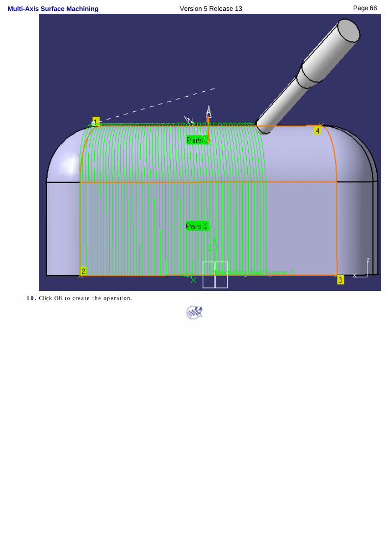
10. Click OK to create the operation.
68Page Multi-Axis Surface Machining Version 5 Release 13
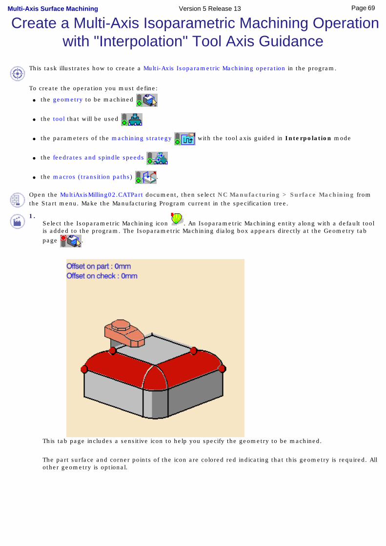
Create a Multi-Axis Isoparametric Machining Operation with "Interpolation" Tool Axis Guidance
This task illustrates how to create a Multi-Axis Isoparametric Machining operation in the program.
To create the operation you must define:
● the geometry to be machined
● the tool that will be used
● the parameters of the machining strategy with the tool axis guided in Interpolation mode
● the feedrates and spindle speeds
● the macros (transition paths) .
Open the MultiAxisMilling02.CATPart document, then select NC Manufacturing > Surface Machining from the Start menu. Make the Manufacturing Program current in the specification tree.
1.Select the Isoparametric Machining icon . An Isoparametric Machining entity along with a default tool is added to the program. The Isoparametric Machining dialog box appears directly at the Geometry tab
page .
This tab page includes a sensitive icon to help you specify the geometry to be machined.
The part surface and corner points of the icon are colored red indicating that this geometry is required. All other geometry is optional.
69Page Multi-Axis Surface Machining Version 5 Release 13

2. Click the red part surface in the icon then select the desired surface in the 3D window.
The Face Selection toolbar appears to help you select faces or belts of faces. These can be adjacent or non-adjacent. For more information please refer to Non-Adjacent Belts of Faces.
A default reference tool axis (A) is displayed. You can double click on this axis to modify it.
3. Click a red point in the icon then select the four corner points of the selected surface.
Machining starts from point 1 to point 2, and finishes either from point 3 to 4 or 4 to 3 (depending on the One way or Zig zag tool path style).
The part surface and corner points of the icon are now colored green indicating that this geometry is now defined.
4. Select the Strategy tab page to specify parameters for:
● Tool axis guidance:
● Machining:
70Page Multi-Axis Surface Machining Version 5 Release 13
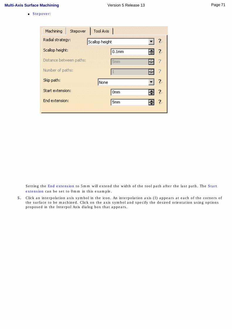
● Stepover:
Setting the End extension to 5mm will extend the width of the tool path after the last path. The Start extension can be set to 0mm in this example.
5. Click an interpolation axis symbol in the icon. An interpolation axis (I) appears at each of the corners of the surface to be machined. Click on the axis symbol and specify the desired orientation using options proposed in the Interpol Axis dialog box that appears.
71Page Multi-Axis Surface Machining Version 5 Release 13
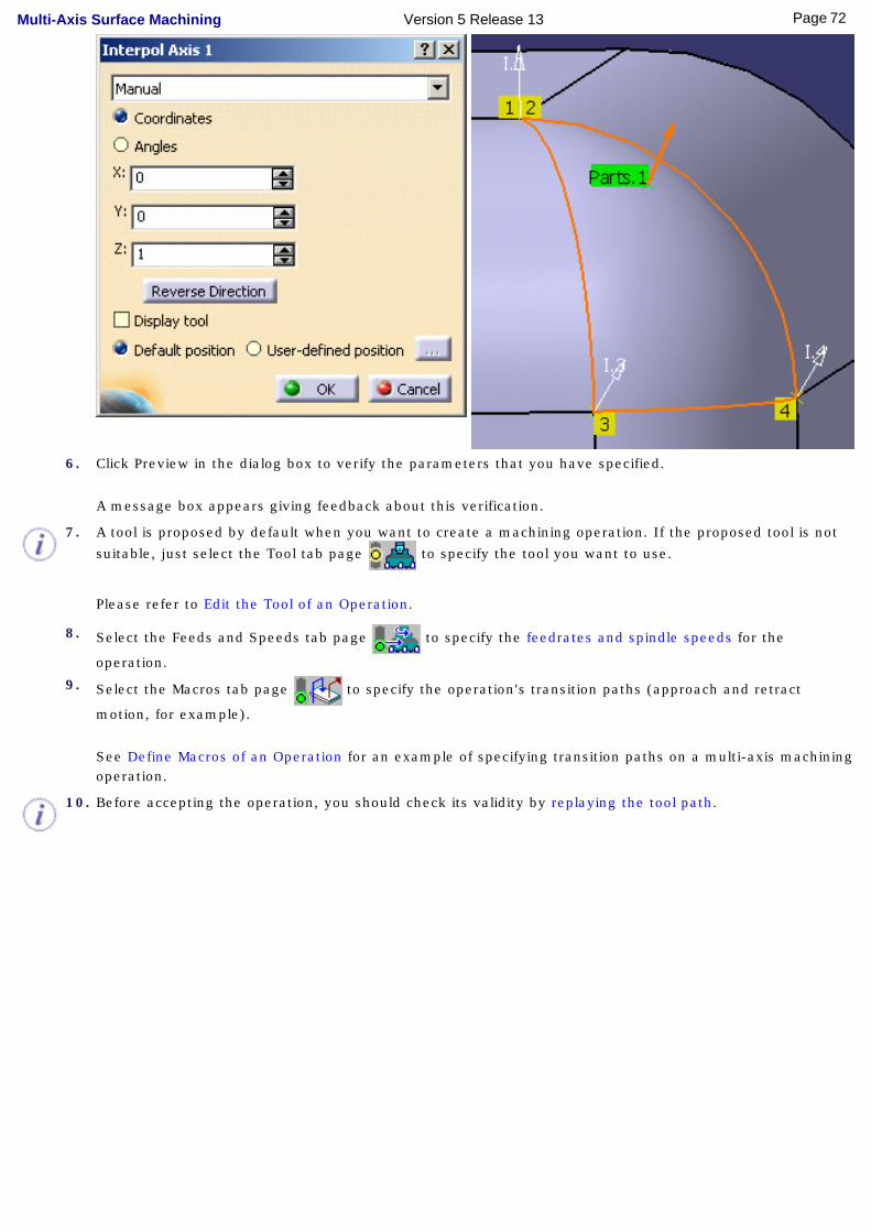
6. Click Preview in the dialog box to verify the parameters that you have specified.
A message box appears giving feedback about this verification.
7. A tool is proposed by default when you want to create a machining operation. If the proposed tool is not
suitable, just select the Tool tab page to specify the tool you want to use.
Please refer to Edit the Tool of an Operation.
8. Select the Feeds and Speeds tab page to specify the feedrates and spindle speeds for the
operation.
9. Select the Macros tab page to specify the operation's transition paths (approach and retract
motion, for example).
See Define Macros of an Operation for an example of specifying transition paths on a multi-axis machining operation.
10. Before accepting the operation, you should check its validity by replaying the tool path.
72Page Multi-Axis Surface Machining Version 5 Release 13
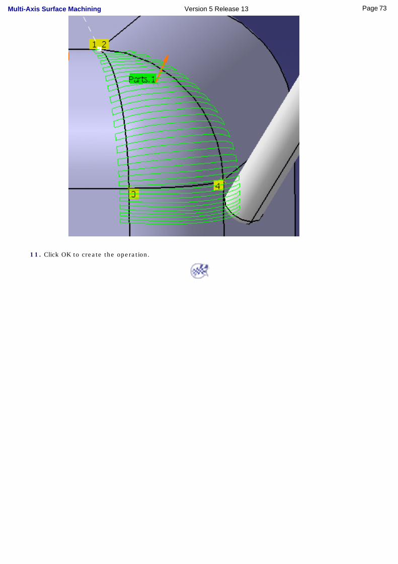
11. Click OK to create the operation.
73Page Multi-Axis Surface Machining Version 5 Release 13

Auxiliary OperationsThe tasks for inserting auxiliary operations in the manufacturing program are documented in the NC Manufacturing Infrastructure User's Guide.
Insert Tool Change: Select the Tool Change icon then select the tool type to be referenced in the tool change.
Insert Machine Rotation: Select the Machine Rotation icon then specify the tool rotation characteristics.
Insert Machining Axis System Change: Select the Machining Change icon then specify the characteristics of the new machining axis system.
Insert PP Instruction: Select the PP Instruction icon then enter the syntax of the PP instruction.
Insert COPY Operator (P2 functionality): Select the COPY Operator icon then select the reference operation. You can then specify the number of copies and the characteristics of the transformation.
Insert TRACUT Operator (P2 functionality): Select the TRACUT Operator icon then select the reference operation. You can then specify the characteristics of the transformation.
Insert Copy Transformation Instruction: Select the Copy Transformation icon then select the reference operation. You can then specify the number of copies and the characteristics of the transformation.
74Page Multi-Axis Surface Machining Version 5 Release 13
Part Operations, Manufacturing Programs and Machining Processes
The tasks for creating and managing Part Operations, Manufacturing Programs and Machining Processes are documented in the NC Manufacturing Infrastructure User's Guide.
Create and Edit a Part Operation: Select the Part Operation icon then specify the entities to be referenced by the part operation: machine tool, machining axis system, tool change point, part set up, and so on.
Create and Edit a Manufacturing Program: Select the Manufacturing Program icon to add a program to the current part operation then insert all necessary program entities: machining operations, tool changes, PP instructions, and so on.
Create a Machining Process: Select the Machining Process icon to create a machining process, which can then be stored in a catalog.
Apply a Machining Process: Select the Open Catalog icon to access the machining process to be applied to selected geometry.
75Page Multi-Axis Surface Machining Version 5 Release 13

NC Manufacturing EntitiesThe tasks for creating and managing specific entities of the NC manufacturing environment are documented in the NC Manufacturing Infrastructure User's Guide.
● Edit the Tool of a Machining Operation: Double click the machining operation in the program and select the Tool tab page to edit the tool characteristics or search for another tool.
● Edit a Tool in the Resource List: Double click a tool in the resource list and edit the tool characteristics in the Tool Definition dialog box.
● Edit a Tool Assembly in the Resource List: Double click a tool assembly in the resource list and edit the tool characteristics in the Tool Definition dialog box.
● Replace Tools in Resource List: Click the Replace Tools icon to rename tools already used in your document.
● Specify Tool Compensation Information: Double click a tool referenced in the program or resource list and specify the tool compensation information in the Compensation tab page of the Tool Definition dialog box .
● Create and Use Machining Patterns: Select Insert > Machining Feature > Machining Pattern then select a pattern of holes to be machined.
● Manufacturing View: Select a feature using the Manufacturing View and create operations based on this feature.
● Define Macros on a Milling Operation: Select the Macros tab page when creating or editing a milling operation, then specify the transition paths of the macros to be used in the operation.
● Define Macros on an Axial Machining Operation: Select the Macros tab page when creating or editing an axial machining operation, then specify the transition paths of the macros to be used in the operation.
● Build and Use a Macros Catalog.
● Manage the Status of Manufacturing Entities: Use the status lights to know whether or not your operation is correctly defined.
● Design or User Parameters in PP Instruction and APT Output.
76Page Multi-Axis Surface Machining Version 5 Release 13
Verification, Simulation and Program OutputThe tasks for using capabilities such as tool path verification, material removal simulation, and production of NC output data are documented in the NC Manufacturing Infrastructure User's Guide.
Replay Tool Path: Select the Tool Path Replay icon then specify the display options for an animated tool path display of the manufacturing program of machining operation.Simulate Material Removal: Select the desired icon in the Tool Path Replay dialog box to run a material removal simulation either in Photo or Video mode.
● Generate APT Source Code in Batch Mode: Select the Generate NC Code in Batch Mode icon then select the manufacturing program to be processed and define the APT source processing options.
● Generate NC Code in Batch Mode: Select the Generate NC Code in Batch Mode icon then select the manufacturing program to be processed and define the NC code processing options.
● Generate Clfile Code in Batch Mode: Select the Generate NC Code in Batch Mode icon then select the manufacturing program to be processed and define the Clfile processing options.
● Generate a CGR File in Batch Mode: Select the Generate NC Code in Batch Mode icon then select the manufacturing program to be processed and define the CGR file processing options.
● MfgBatch Utility that allows you to generate NC data files from a manufacturing program by
means of an executable program under Windows or a shell under UNIX.
Batch Queue Management: Manage tool path computation outside the interactive CATIA session, with the possibility of scheduling the execution of several batch jobs.Generate NC Code in Interactive Mode: Select the Generate NC Code Interactively icon then select the manufacturing program to be processed and define processing options.Generate Documentation: Select the Generate Documentation icon to produce shop floor documentation in HTML format. Import an APT Source into the Program: Select the APT Import contextual command to insert an existing APT source into the current manufacturing program.
77Page Multi-Axis Surface Machining Version 5 Release 13

Workbench DescriptionThis section contains the description of the menu commands and icon toolbars that are specific to the Surface Machining workbench when Multi-Axis Surface Machining is installed.
Menu BarToolbars
Specification Tree
78Page Multi-Axis Surface Machining Version 5 Release 13

Multi-Axis Surface Machining Menu Bar The menu commands that are made available when Multi-Axis Surface Machining is installed are described below.
Start File Edit View Insert Tools Windows Help
Tasks corresponding to general menu commands are described in the CATIA Version 5 Infrastructure User's Guide.
Insert Menu
Insert > Machining Operations > Multi-Axis Machining Operations Command... Description...
Multi-Axis SweepingCreate a Multi-Axis Sweeping Operation
Isoparametric MachiningCreate an Isoparametric Machining Operation
Multi-Axis Contour Driven Create a Multi-Axis Contour Driven Operation
Multi-Axis Curve Machining Create a Multi-Axis Curve Following Operation
79Page Multi-Axis Surface Machining Version 5 Release 13
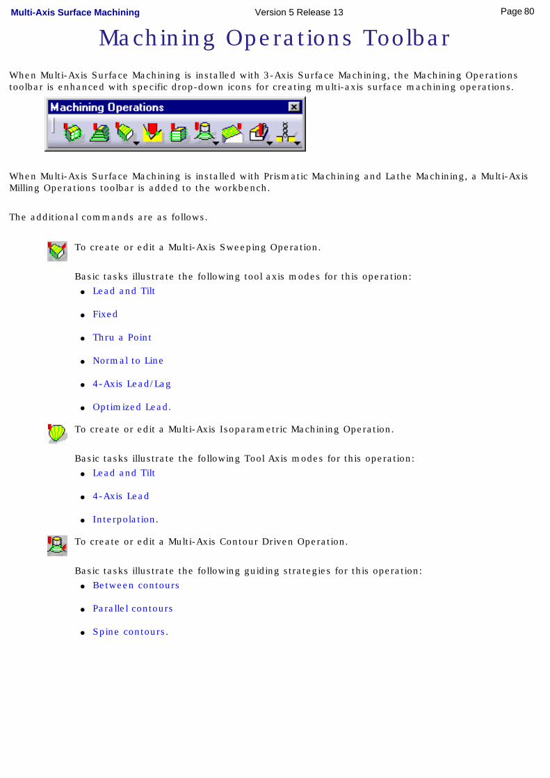
Machining Operations ToolbarWhen Multi-Axis Surface Machining is installed with 3-Axis Surface Machining, the Machining Operations toolbar is enhanced with specific drop-down icons for creating multi-axis surface machining operations.
When Multi-Axis Surface Machining is installed with Prismatic Machining and Lathe Machining, a Multi-Axis Milling Operations toolbar is added to the workbench.
The additional commands are as follows.
To create or edit a Multi-Axis Sweeping Operation.
Basic tasks illustrate the following tool axis modes for this operation: ● Lead and Tilt
● Fixed
● Thru a Point
● Normal to Line
● 4-Axis Lead/Lag
● Optimized Lead.
To create or edit a Multi-Axis Isoparametric Machining Operation.
Basic tasks illustrate the following Tool Axis modes for this operation: ● Lead and Tilt
● 4-Axis Lead
● Interpolation.
To create or edit a Multi-Axis Contour Driven Operation.
Basic tasks illustrate the following guiding strategies for this operation: ● Between contours
● Parallel contours
● Spine contours.
80Page Multi-Axis Surface Machining Version 5 Release 13

To create or edit a Multi-Axis Curve Machining Operation.
Basic tasks illustrate the following machining modes for this operation: ● Contact
● Between two curves with Tip / Interpolation machining
● Between a curve and part with Side / Interpolation machining.
The other toolbars of this workbench are described in the 3-Axis Surface Machining User's Guide.
81Page Multi-Axis Surface Machining Version 5 Release 13

Specification TreeHere is an example of a Process Product Resources (PPR) specification tree for NC Manufacturing products.
Process List is a plan that gives all the activities and machining operations required to transform a part from a rough to a finished state.
● Part Operation defines the manufacturing resources and the reference data.
● Manufacturing Program is the list of all of the operations and tool changes performed. The example above shows that:
❍ Drilling.1 is complete and has not been computed
❍ Drilling.2 is complete but has been computed (by means of a replay)
❍ Drilling.3 does not have all of the necessary data (indicated by the exclamation mark symbol)
❍ Drilling.4 has been deactivated by the user (indicated by the brackets symbol)
❍ Drilling.5 has been modified and needs to be recomputed (indicated by the update symbol).
Product List gives all of the parts to machine as well as CATPart documents containing complementary geometry. Resources List gives all of the resources such as machine or tools that can be used in the program.
82Page Multi-Axis Surface Machining Version 5 Release 13

CustomizingTasks for customizing your NC Manufacturing environment are described in the NC Manufacturing Infrastructure User's Guide.
NC Manufacturing Settings Build a Tools Catalog
Access External Tools Catalogs Add User Attributes on Tool Types
PP Word Syntaxes NC Documentation
Workbenches and Tool Bars
83Page Multi-Axis Surface Machining Version 5 Release 13

Customizing Settings for NC Manufacturing
This section describes how to customize settings for NC Manufacturing.
Before you start your first working session, you can customize the settings to suit your working habits. Your customized settings are stored in permanent setting files: they will not be lost at the end of your session.
1. Select Tools > Options from the menu bar: the Options dialog box appears.
2. Select the NC Manufacturing category in the tree to the left. The options for NC Manufacturing settings appear, organized in tab pages.
3. Select the tab corresponding to the parameters to be customized.
Parameters in this tab... Allow you to customize...
General general settings for all NC Manufacturing products
Resources tooling, feeds&speeds and resource files
Operation machining operations
Output PP files and NC data output
Program manufacturing programs (sequencing, and so on)
Photo / Video material removal simulation
4. Change theses options according to your needs.
5. Click OK to save the settings and quit the Options dialog box.
84Page Multi-Axis Surface Machining Version 5 Release 13
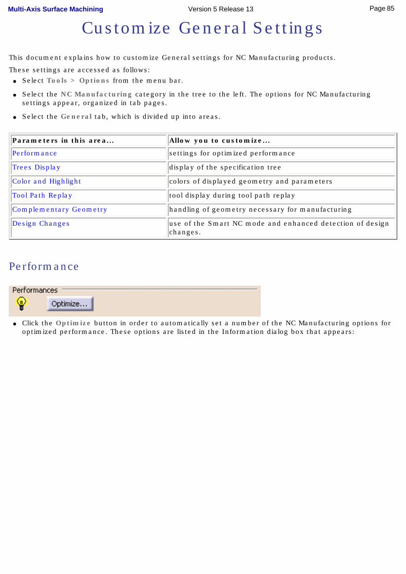
Customize General Settings
This document explains how to customize General settings for NC Manufacturing products.
These settings are accessed as follows:● Select Tools > Options from the menu bar.
● Select the NC Manufacturing category in the tree to the left. The options for NC Manufacturing settings appear, organized in tab pages.
● Select the General tab, which is divided up into areas.
Parameters in this area... Allow you to customize...
Performance settings for optimized performance
Trees Display display of the specification tree
Color and Highlight colors of displayed geometry and parameters
Tool Path Replay tool display during tool path replay
Complementary Geometry handling of geometry necessary for manufacturing
Design Changes use of the Smart NC mode and enhanced detection of design changes.
Performance
● Click the Optimize button in order to automatically set a number of the NC Manufacturing options for optimized performance. These options are listed in the Information dialog box that appears:
85Page Multi-Axis Surface Machining Version 5 Release 13
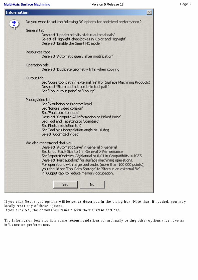
If you click Yes, these options will be set as described in the dialog box. Note that, if needed, you may locally reset any of these options.If you click No, the options will remain with their current settings.
The Information box also lists some recommendations for manually setting other options that have an influence on performance.
86Page Multi-Axis Surface Machining Version 5 Release 13
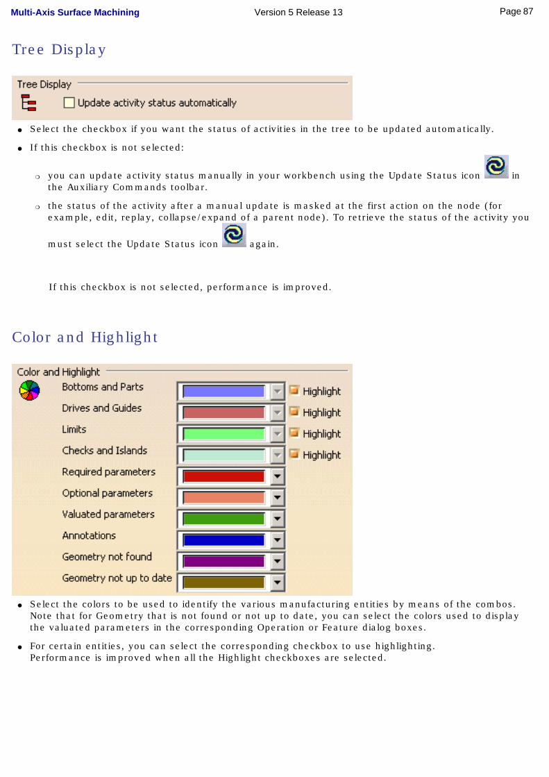
Tree Display
● Select the checkbox if you want the status of activities in the tree to be updated automatically.
● If this checkbox is not selected:
❍ you can update activity status manually in your workbench using the Update Status icon in the Auxiliary Commands toolbar.
❍ the status of the activity after a manual update is masked at the first action on the node (for example, edit, replay, collapse/expand of a parent node). To retrieve the status of the activity you
must select the Update Status icon again.
If this checkbox is not selected, performance is improved.
Color and Highlight
● Select the colors to be used to identify the various manufacturing entities by means of the combos. Note that for Geometry that is not found or not up to date, you can select the colors used to display the valuated parameters in the corresponding Operation or Feature dialog boxes.
● For certain entities, you can select the corresponding checkbox to use highlighting. Performance is improved when all the Highlight checkboxes are selected.
87Page Multi-Axis Surface Machining Version 5 Release 13
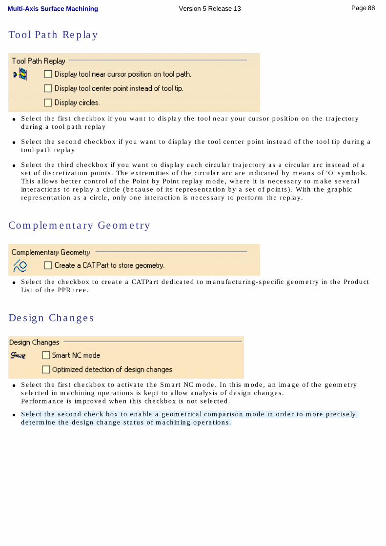
Tool Path Replay
● Select the first checkbox if you want to display the tool near your cursor position on the trajectory during a tool path replay
● Select the second checkbox if you want to display the tool center point instead of the tool tip during a tool path replay
● Select the third checkbox if you want to display each circular trajectory as a circular arc instead of a set of discretization points. The extremities of the circular arc are indicated by means of 'O' symbols.This allows better control of the Point by Point replay mode, where it is necessary to make several interactions to replay a circle (because of its representation by a set of points). With the graphic representation as a circle, only one interaction is necessary to perform the replay.
Complementary Geometry
● Select the checkbox to create a CATPart dedicated to manufacturing-specific geometry in the Product List of the PPR tree.
Design Changes
● Select the first checkbox to activate the Smart NC mode. In this mode, an image of the geometry selected in machining operations is kept to allow analysis of design changes.Performance is improved when this checkbox is not selected.
● Select the second check box to enable a geometrical comparison mode in order to more precisely determine the design change status of machining operations.
88Page Multi-Axis Surface Machining Version 5 Release 13

Customize Resource Settings
This document explains how to customize Resource settings for NC Manufacturing products.
These settings are accessed as follows:● Select Tools > Options from the menu bar.
● Select the NC Manufacturing category in the tree to the left. The options for NC Manufacturing settings appear, organized in tab pages.
● Select the Resources tab, which is divided up into areas.
Parameters in this area... Allow you to customize...
Catalogs and Files the path name for resource files
Tool Selection the selection of tools
Automatic Compute from Tool Feeds and Speeds
the update of feeds and speeds according to tooling data
Tool Query Mode in Machining Processes Instantiation
tool queries in machining processes
Catalogs and Files
● Enter the path of the folder containing tool catalogs, PP tables, macros, and machining processes. You can choose a folder by clicking the [...] button.
You can concatenate paths using:❍ a semi colon (;) character for Windows NT platforms.
❍ a colon (:) character for UNIX platform.
For example, if the concatenated folders E:\DownloadOfCXR12rel\intel_a\startup and e:\users\jmn\NC in the figure above contain PP tables, then those PP tables will be available for selection in the Part Operation's Machine Editor dialog box.
Please note, however, that:● PP tables must be contained in folders named Manufacturing\PPTables
● tools must be contained in folders named Manufacturing\Tools.
Tool Selection
● Select the first checkbox if you want to to activate an automatic query after each modification of a tool parameter. Performance is improved when this checkbox is not selected.
● Select the second checkbox if you want to preview the tool after selection.
89Page Multi-Axis Surface Machining Version 5 Release 13
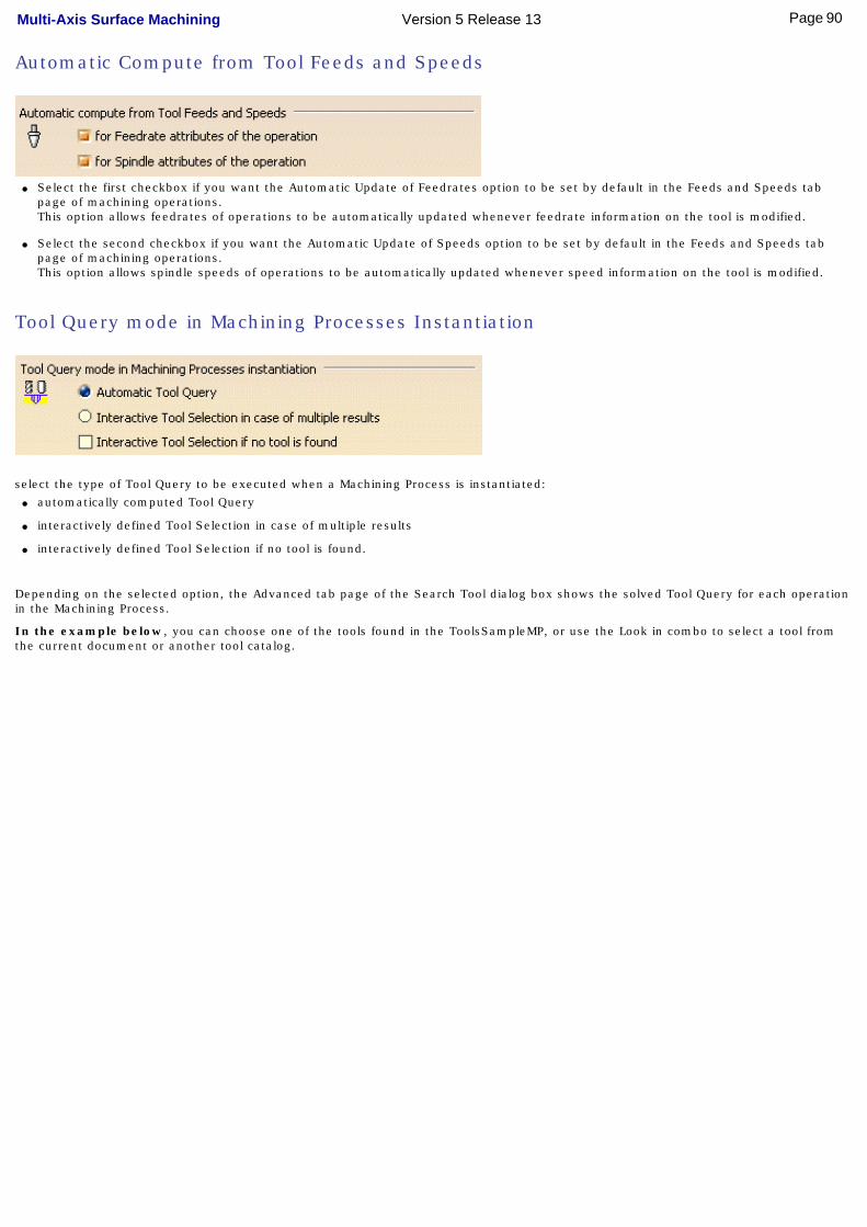
Automatic Compute from Tool Feeds and Speeds
● Select the first checkbox if you want the Automatic Update of Feedrates option to be set by default in the Feeds and Speeds tab page of machining operations.This option allows feedrates of operations to be automatically updated whenever feedrate information on the tool is modified.
● Select the second checkbox if you want the Automatic Update of Speeds option to be set by default in the Feeds and Speeds tab page of machining operations.This option allows spindle speeds of operations to be automatically updated whenever speed information on the tool is modified.
Tool Query mode in Machining Processes Instantiation
select the type of Tool Query to be executed when a Machining Process is instantiated:● automatically computed Tool Query
● interactively defined Tool Selection in case of multiple results
● interactively defined Tool Selection if no tool is found.
Depending on the selected option, the Advanced tab page of the Search Tool dialog box shows the solved Tool Query for each operation in the Machining Process.
In the example below, you can choose one of the tools found in the ToolsSampleMP, or use the Look in combo to select a tool from the current document or another tool catalog.
90Page Multi-Axis Surface Machining Version 5 Release 13
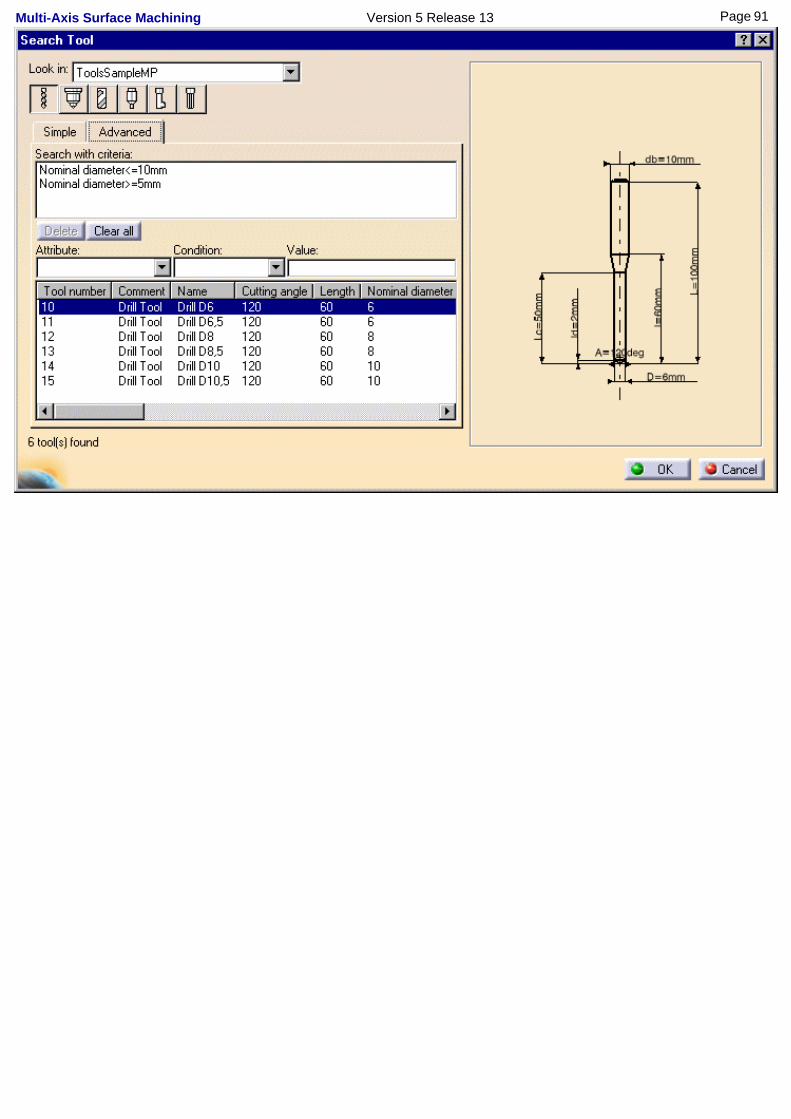
91Page Multi-Axis Surface Machining Version 5 Release 13
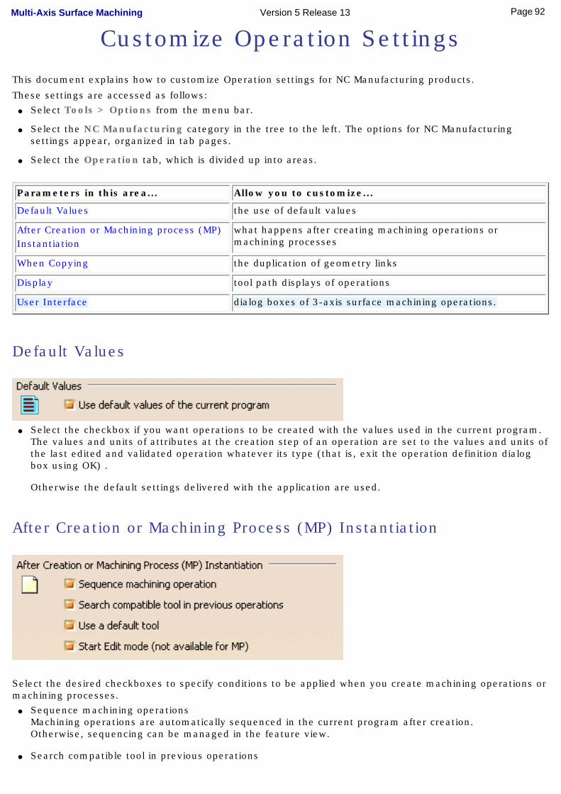
Customize Operation Settings
This document explains how to customize Operation settings for NC Manufacturing products.
These settings are accessed as follows:● Select Tools > Options from the menu bar.
● Select the NC Manufacturing category in the tree to the left. The options for NC Manufacturing settings appear, organized in tab pages.
● Select the Operation tab, which is divided up into areas.
Parameters in this area... Allow you to customize...
Default Values the use of default values
After Creation or Machining process (MP) Instantiation
what happens after creating machining operations or machining processes
When Copying the duplication of geometry links
Display tool path displays of operations
User Interface dialog boxes of 3-axis surface machining operations.
Default Values
● Select the checkbox if you want operations to be created with the values used in the current program. The values and units of attributes at the creation step of an operation are set to the values and units of the last edited and validated operation whatever its type (that is, exit the operation definition dialog box using OK) .
Otherwise the default settings delivered with the application are used.
After Creation or Machining Process (MP) Instantiation
Select the desired checkboxes to specify conditions to be applied when you create machining operations or machining processes.
● Sequence machining operationsMachining operations are automatically sequenced in the current program after creation. Otherwise, sequencing can be managed in the feature view.
● Search compatible tool in previous operations
92Page Multi-Axis Surface Machining Version 5 Release 13
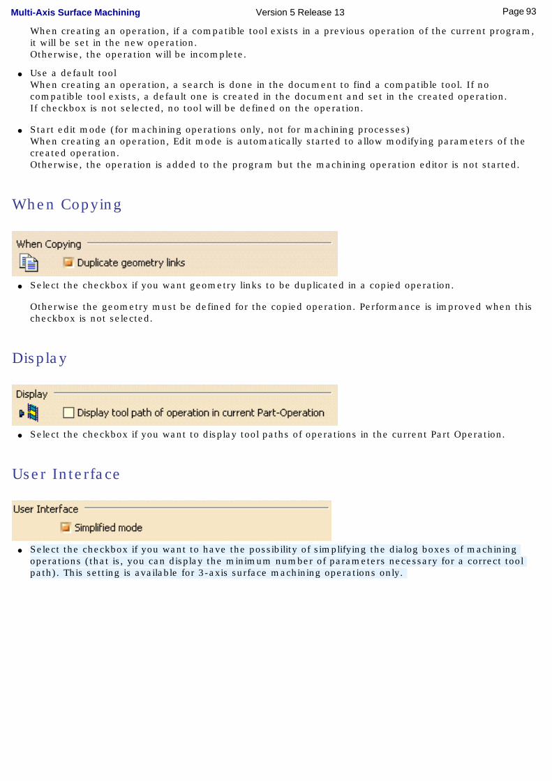
When creating an operation, if a compatible tool exists in a previous operation of the current program, it will be set in the new operation. Otherwise, the operation will be incomplete.
● Use a default toolWhen creating an operation, a search is done in the document to find a compatible tool. If no compatible tool exists, a default one is created in the document and set in the created operation.If checkbox is not selected, no tool will be defined on the operation.
● Start edit mode (for machining operations only, not for machining processes)When creating an operation, Edit mode is automatically started to allow modifying parameters of the created operation.Otherwise, the operation is added to the program but the machining operation editor is not started.
When Copying
● Select the checkbox if you want geometry links to be duplicated in a copied operation.
Otherwise the geometry must be defined for the copied operation. Performance is improved when this checkbox is not selected.
Display
● Select the checkbox if you want to display tool paths of operations in the current Part Operation.
User Interface
● Select the checkbox if you want to have the possibility of simplifying the dialog boxes of machining operations (that is, you can display the minimum number of parameters necessary for a correct tool path). This setting is available for 3-axis surface machining operations only.
93Page Multi-Axis Surface Machining Version 5 Release 13

Customize Output Settings
This document explains how to customize Output settings for NC Manufacturing products.
These settings are accessed as follows:● Select Tools > Options from the menu bar.
● Select the NC Manufacturing category in the tree to the left. The options for NC Manufacturing settings appear, organized in tab pages.
● Select the Output tab, which is divided up into areas.
Parameters in this area... Allow you to customize...
Post Processor the type of PP files to be used for generating NC code output and the path where these files are located
Tool Path Storage the tool path storage capability
Tool Path Edition the tool path edition capability
During Tool Path Computation contact point storage
Tool Output Point type of tool output point
Tool Output Files ... Location default paths for NC output files storage.
Post Processor
Select the desired Processor option:● None: no Post Processor is defined. NC code output is not possible in this case
● Cenit: you can choose from among the Post Processor parameter files proposed by Cenit to generate your NC code
● IMS: you can choose from among the Post Processor parameter files proposed by Intelligent Manufacturing Software (IMS) to generate your NC code
● ICAM: you can choose from among the Post Processor parameter files proposed by ICAM Technologies Corporation (ICAM) to generate your NC code.
Enter the path of the folder containing Post processors. You can choose a folder by clicking the [...] button. File concatenation is possible.
94Page Multi-Axis Surface Machining Version 5 Release 13

Tool Path Storage
Select the desired option to store tool path data either in the current document or in an external file (as a tpl file).
For operations with large tool paths (more than 100 000 points), tool path storage in an external file is recommended.
Tool Path Edition
Select the checkbox if you want to be able to edit tool paths even when the operation is locked.
This capability is available only for activities with a tool path node in the specification tree.
During Tool Path Computation
Select the checkbox if you want to store contact points in the tool path.
Performance is improved when this checkbox is not selected.
Tool Output Point
Select the desired option to select either the tool tip or tool center point as output point.
Performance is better when the Tool Tip option is selected.
95Page Multi-Axis Surface Machining Version 5 Release 13

Default File Locations
Specify default locations for storing Tool Path files, NC Documentation, and NC Code output.
You can store tool paths files (tpl files) in the same folder as the CATProcess by selecting the checkbox. This allows you to store these files according to your CATProcess context. Otherwise, you can choose another location by clicking the [...] button.
For NC Documentation, and NC Code output you can choose a folder easily by clicking the [...] button.
You can customize the extension to be used for NC Code output (by default, the suffix used is CATNCCode).
96Page Multi-Axis Surface Machining Version 5 Release 13
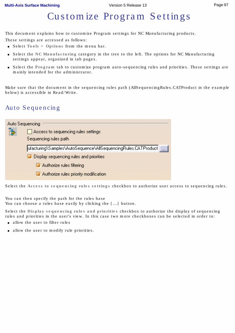
Customize Program Settings
This document explains how to customize Program settings for NC Manufacturing products.
These settings are accessed as follows:● Select Tools > Options from the menu bar.
● Select the NC Manufacturing category in the tree to the left. The options for NC Manufacturing settings appear, organized in tab pages.
● Select the Program tab to customize program auto-sequencing rules and priorities. These settings are mainly intended for the administrator.
Make sure that the document in the sequencing rules path (AllSequencingRules.CATProduct in the example below) is accessible in Read/Write.
Auto Sequencing
Select the Access to sequencing rules settings checkbox to authorize user access to sequencing rules.
You can then specify the path for the rules base You can choose a rules base easily by clicking the [...] button.
Select the Display sequencing rules and priorities checkbox to authorize the display of sequencing rules and priorities in the user's view. In this case two more checkboxes can be selected in order to:
● allow the user to filter rules
● allow the user to modify rule priorities.
97Page Multi-Axis Surface Machining Version 5 Release 13
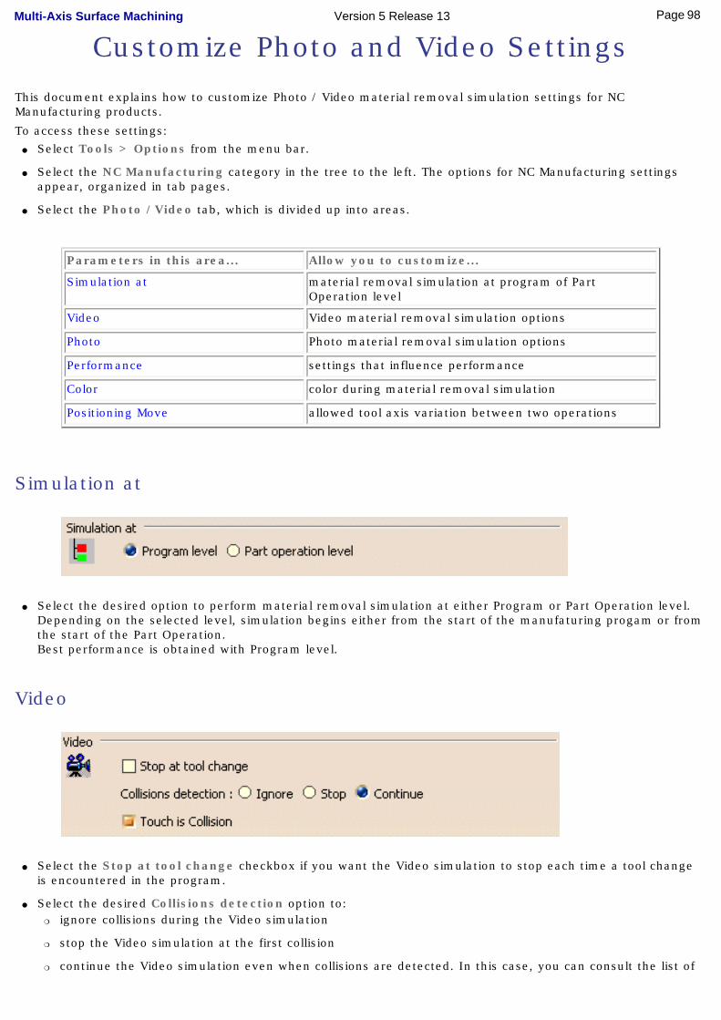
Customize Photo and Video Settings
This document explains how to customize Photo / Video material removal simulation settings for NC Manufacturing products.
To access these settings:● Select Tools > Options from the menu bar.
● Select the NC Manufacturing category in the tree to the left. The options for NC Manufacturing settings appear, organized in tab pages.
● Select the Photo /Video tab, which is divided up into areas.
Parameters in this area... Allow you to customize...
Simulation at material removal simulation at program of Part Operation level
Video Video material removal simulation options
Photo Photo material removal simulation options
Performance settings that influence performance
Color color during material removal simulation
Positioning Move allowed tool axis variation between two operations
Simulation at
● Select the desired option to perform material removal simulation at either Program or Part Operation level. Depending on the selected level, simulation begins either from the start of the manufaturing progam or from the start of the Part Operation. Best performance is obtained with Program level.
Video
● Select the Stop at tool change checkbox if you want the Video simulation to stop each time a tool change is encountered in the program.
● Select the desired Collisions detection option to: ❍ ignore collisions during the Video simulation
❍ stop the Video simulation at the first collision
❍ continue the Video simulation even when collisions are detected. In this case, you can consult the list of
98Page Multi-Axis Surface Machining Version 5 Release 13
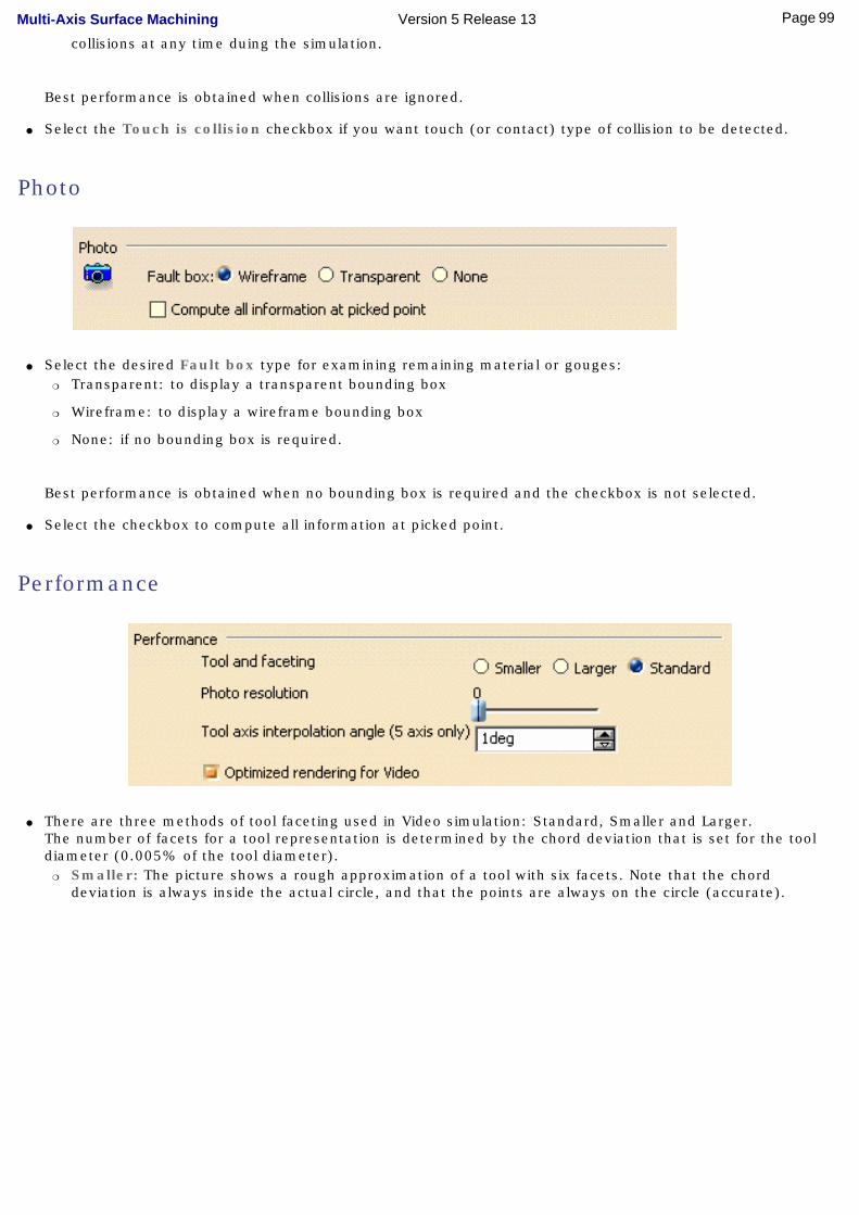
collisions at any time duing the simulation.
Best performance is obtained when collisions are ignored.
● Select the Touch is collision checkbox if you want touch (or contact) type of collision to be detected.
Photo
● Select the desired Fault box type for examining remaining material or gouges:❍ Transparent: to display a transparent bounding box
❍ Wireframe: to display a wireframe bounding box
❍ None: if no bounding box is required.
Best performance is obtained when no bounding box is required and the checkbox is not selected.
● Select the checkbox to compute all information at picked point.
Performance
● There are three methods of tool faceting used in Video simulation: Standard, Smaller and Larger. The number of facets for a tool representation is determined by the chord deviation that is set for the tool diameter (0.005% of the tool diameter).
❍ Smaller: The picture shows a rough approximation of a tool with six facets. Note that the chord deviation is always inside the actual circle, and that the points are always on the circle (accurate).
99Page Multi-Axis Surface Machining Version 5 Release 13

This is the most accurate method for the Arc through Three Points command.
❍ Standard: The picture shows a rough approximation of a tool with six facets. Note that the chord deviation is partly inside and partly outside the actual circle, and that the points are not always on the circle.
This is the best method for material removal simulation. However, this is not suitable for the Arc through Three Points command.
❍ Larger: The picture shows a rough approximation of a tool with six facets. Note that the chord deviation is outside the actual circle, and that the points are not on the circle.
This is not suitable for the Arc through Three Points command.However, it can be useful for gouge detection.
100Page Multi-Axis Surface Machining Version 5 Release 13
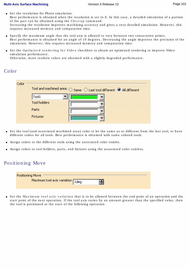
● Set the resolution for Photo simulation. Best performance is obtained when the resolution is set to 0. In this case, a detailed simulation of a portion of the part can be obtained using the Closeup command.Increasing the resolution improves machining accuracy and gives a very detailed simulation. However, this requires increased memory and computation time.
● Specify the maximum angle that the tool axis is allowed to vary between two consecutive points. Best performance is obtained for an angle of 10 degrees. Decreasing the angle improves the precision of the simulation. However, this requires increased memory and computation time.
● Set the Optimized rendering for Video checkbox to obtain an optimized rendering to improve Video simulation performance.Otherwise, more realistic colors are obtained with a slightly degraded performance.
Color
● Set the tool (and associated machined area) color to be the same as or different from the last tool, or have different colors for all tools. Best performance is obtained with same colored tools.
● Assign colors to the different tools using the associated color combo.
● Assign colors to tool holders, parts, and fixtures using the associated color combos.
Positioning Move
● Set the Maximum tool axis variation that is to be allowed between the end point of an operation and the start point of the next operation. If the tool axis varies by an amount greater than the specified value, then the tool is positioned at the start of the following operation.
101Page Multi-Axis Surface Machining Version 5 Release 13
Reference InformationReference information that is specific to the Multi-Axis Surface Machining product can be found in this section.
Multi-Axis SweepingMulti-Axis Isoparametric Machining
Multi-Axis Contour DrivenMulti-Axis Curve Machining
Collision Checking
Essential reference information on the following topics is provided in the NC Manufacturing Infrastructure User's Guide.
NC Manufacturing ResourcesNC Macros
PP Tables and PP Word SyntaxesFeeds and Speeds
APT FormatsCLfile Formats
102Page Multi-Axis Surface Machining Version 5 Release 13
Multi-Axis Sweeping The information in this section will help you create and edit Multi-Axis Sweeping operations in your NC manufacturing program.
Select the icon, then select the geometry to be machined .
A number of strategy parameters are available for defining:
● machining criteria
● stepover conditions
● tool axis guidance
● cutter compensation.
Specify the tool to be used , feeds and speeds , and NC macros as needed.
Multi-Axis Sweeping: Strategy Parameters
Multi-Axis Sweeping: Machining ParametersTool path styleIndicates the cutting mode of the operation: Zig Zag: the machining direction is reversed from one path to the nextOne way: the same machining direction is used from one path to the next.Machining toleranceSpecifies the maximum allowed distance between the theoretical and computed tool path. Maximum discretization stepEnsures linearity between points that are far apart. Maximum discretization angleSpecifies the maximum angular change of tool axis between tool positions. It is used to add more tool positions (points and axis) if value is exceeded. Minimum path lengthSpecifies the minimum length of path to be taken into account.
Multi-Axis Sweeping: Stepover ParametersRadial strategy modeDefines how the distance between two consecutive paths is to be computed. Scallop heightSpecifies the maximum scallop height between two consecutive tool paths in a radial strategy. Distance between pathsDefines the maximum distance between two consecutive tool paths in a radial strategy. Number of pathsDefines the number of tool paths in a radial strategy. Stepover sideSpecifies the side of the guiding plane that will be used to determine the overall machining direction.
Multi-Axis Sweeping: Tool Axis Parameters
103Page Multi-Axis Surface Machining Version 5 Release 13
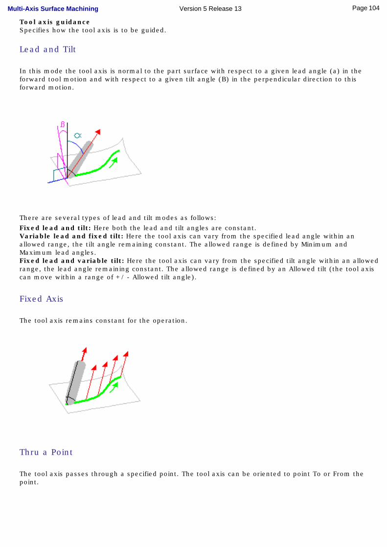
Tool axis guidanceSpecifies how the tool axis is to be guided.
Lead and Tilt
In this mode the tool axis is normal to the part surface with respect to a given lead angle (a) in the forward tool motion and with respect to a given tilt angle (B) in the perpendicular direction to this forward motion.
There are several types of lead and tilt modes as follows:Fixed lead and tilt: Here both the lead and tilt angles are constant.Variable lead and fixed tilt: Here the tool axis can vary from the specified lead angle within an allowed range, the tilt angle remaining constant. The allowed range is defined by Minimum and Maximum lead angles.Fixed lead and variable tilt: Here the tool axis can vary from the specified tilt angle within an allowed range, the lead angle remaining constant. The allowed range is defined by an Allowed tilt (the tool axis can move within a range of +/ - Allowed tilt angle).
Fixed Axis
The tool axis remains constant for the operation.
Thru a Point
The tool axis passes through a specified point. The tool axis can be oriented to point To or From the point.
104Page Multi-Axis Surface Machining Version 5 Release 13
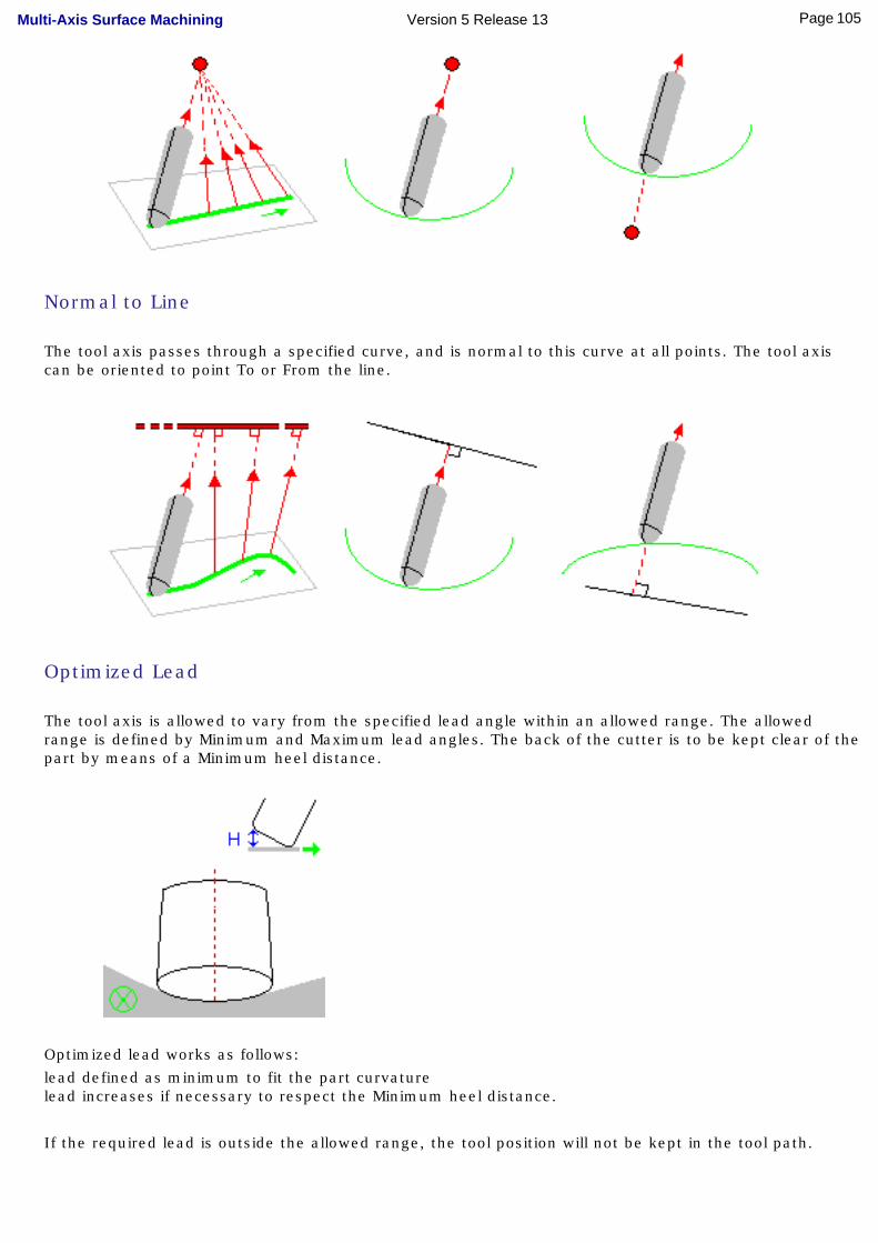
Normal to Line
The tool axis passes through a specified curve, and is normal to this curve at all points. The tool axis can be oriented to point To or From the line.
Optimized Lead
The tool axis is allowed to vary from the specified lead angle within an allowed range. The allowed range is defined by Minimum and Maximum lead angles. The back of the cutter is to be kept clear of the part by means of a Minimum heel distance.
Optimized lead works as follows:lead defined as minimum to fit the part curvaturelead increases if necessary to respect the Minimum heel distance.
If the required lead is outside the allowed range, the tool position will not be kept in the tool path.
105Page Multi-Axis Surface Machining Version 5 Release 13
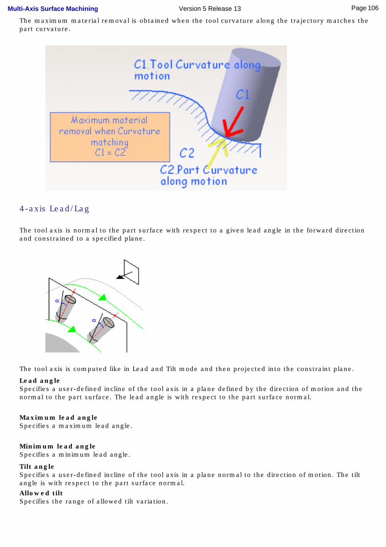
The maximum material removal is obtained when the tool curvature along the trajectory matches the part curvature.
4-axis Lead/Lag
The tool axis is normal to the part surface with respect to a given lead angle in the forward direction and constrained to a specified plane.
The tool axis is computed like in Lead and Tilt mode and then projected into the constraint plane.
Lead angleSpecifies a user-defined incline of the tool axis in a plane defined by the direction of motion and the normal to the part surface. The lead angle is with respect to the part surface normal.
Maximum lead angleSpecifies a maximum lead angle.
Minimum lead angleSpecifies a minimum lead angle.
Tilt angleSpecifies a user-defined incline of the tool axis in a plane normal to the direction of motion. The tilt angle is with respect to the part surface normal. Allowed tiltSpecifies the range of allowed tilt variation.
106Page Multi-Axis Surface Machining Version 5 Release 13
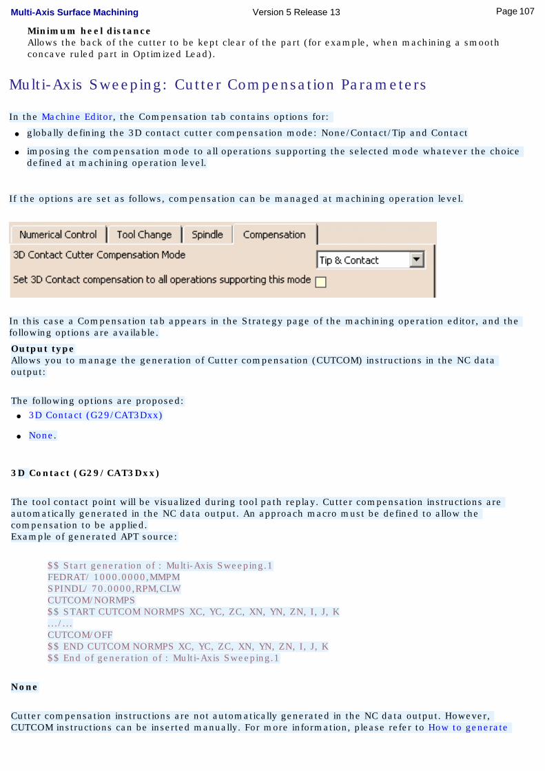
Minimum heel distanceAllows the back of the cutter to be kept clear of the part (for example, when machining a smooth concave ruled part in Optimized Lead).
Multi-Axis Sweeping: Cutter Compensation Parameters
In the Machine Editor, the Compensation tab contains options for:
● globally defining the 3D contact cutter compensation mode: None/Contact/Tip and Contact
● imposing the compensation mode to all operations supporting the selected mode whatever the choice defined at machining operation level.
If the options are set as follows, compensation can be managed at machining operation level.
In this case a Compensation tab appears in the Strategy page of the machining operation editor, and the following options are available.
Output typeAllows you to manage the generation of Cutter compensation (CUTCOM) instructions in the NC data output:
The following options are proposed:● 3D Contact (G29/CAT3Dxx)
● None.
3D Contact (G29/CAT3Dxx)
The tool contact point will be visualized during tool path replay. Cutter compensation instructions are automatically generated in the NC data output. An approach macro must be defined to allow the compensation to be applied.Example of generated APT source:
$$ Start generation of : Multi-Axis Sweeping.1FEDRAT/ 1000.0000,MMPMSPINDL/ 70.0000,RPM,CLWCUTCOM/NORMPS$$ START CUTCOM NORMPS XC, YC, ZC, XN, YN, ZN, I, J, K.../...CUTCOM/OFF$$ END CUTCOM NORMPS XC, YC, ZC, XN, YN, ZN, I, J, K$$ End of generation of : Multi-Axis Sweeping.1
None
Cutter compensation instructions are not automatically generated in the NC data output. However, CUTCOM instructions can be inserted manually. For more information, please refer to How to generate
107Page Multi-Axis Surface Machining Version 5 Release 13
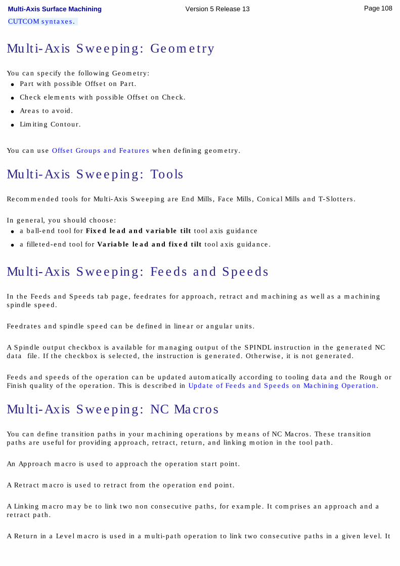
CUTCOM syntaxes.
Multi-Axis Sweeping: Geometry
You can specify the following Geometry:● Part with possible Offset on Part.
● Check elements with possible Offset on Check.
● Areas to avoid.
● Limiting Contour.
You can use Offset Groups and Features when defining geometry.
Multi-Axis Sweeping: Tools
Recommended tools for Multi-Axis Sweeping are End Mills, Face Mills, Conical Mills and T-Slotters.
In general, you should choose:● a ball-end tool for Fixed lead and variable tilt tool axis guidance
● a filleted-end tool for Variable lead and fixed tilt tool axis guidance.
Multi-Axis Sweeping: Feeds and Speeds
In the Feeds and Speeds tab page, feedrates for approach, retract and machining as well as a machining spindle speed.
Feedrates and spindle speed can be defined in linear or angular units.
A Spindle output checkbox is available for managing output of the SPINDL instruction in the generated NC data file. If the checkbox is selected, the instruction is generated. Otherwise, it is not generated.
Feeds and speeds of the operation can be updated automatically according to tooling data and the Rough or Finish quality of the operation. This is described in Update of Feeds and Speeds on Machining Operation.
Multi-Axis Sweeping: NC Macros
You can define transition paths in your machining operations by means of NC Macros. These transition paths are useful for providing approach, retract, return, and linking motion in the tool path.
An Approach macro is used to approach the operation start point.
A Retract macro is used to retract from the operation end point.
A Linking macro may be to link two non consecutive paths, for example. It comprises an approach and a retract path.
A Return in a Level macro is used in a multi-path operation to link two consecutive paths in a given level. It
108Page Multi-Axis Surface Machining Version 5 Release 13

comprises an approach and a retract path.
A Clearance macro can be used in a machining operation to avoid a fixture, for example.
109Page Multi-Axis Surface Machining Version 5 Release 13
Multi-Axis Isoparametric Machining The information in this section will help you create and edit Multi-Axis Isoparametric Machining operations in your NC manufacturing program.
Click the icon, then select the geometry to be machined .
A number of strategy parameters are available for defining:
● machining criteria
● stepover conditions
● tool axis guidance
● cutter compensation.
Specify the tool to be used , feeds and speeds , and NC macros as needed.
Multi-Axis Isoparametric Machining: Strategy Parameters
Multi-Axis Isoparametric Machining: Machining ParametersTool path styleIndicates the cutting mode of the operation:
● Zig Zag: the machining direction is reversed from one path to the next
● One way: the same machining direction is used from one path to the next.
Machining toleranceSpecifies the maximum allowed distance between the theoretical and computed tool path. Maximum discretization stepEnsures linearity between points that are far apart. Maximum discretization angleSpecifies the maximum angular change of tool axis between tool positions. It is used to add more tool positions (points and axis) if value is exceeded.
Multi-Axis Isoparametric Machining: Stepover ParametersRadial strategy modeDefines how the distance between two consecutive paths is to be computed. Scallop heightSpecifies the maximum scallop height between two consecutive tool paths in a radial strategy. Distance between pathsDefines the maximum distance between two consecutive tool paths in a radial strategy. Number of pathsDefines the number of tool paths in a radial strategy. Skip pathGives the possibility of not machining the first path, the last path or both the first and last paths of the toolpath.
Start extensionSpecifies the width of an additional machined area located before the first path on the part.
This value can be either positive (the global machined area is extended) or negative (the global machined area is reduced).
End extensionSpecifies the width of an additional machined area located after the last path on the part.
This value can be either positive (the global machined area is extended) or negative (the global machined area is reduced).
Multi-Axis Isoparametric Machining: Tool Axis Parameters
110Page Multi-Axis Surface Machining Version 5 Release 13
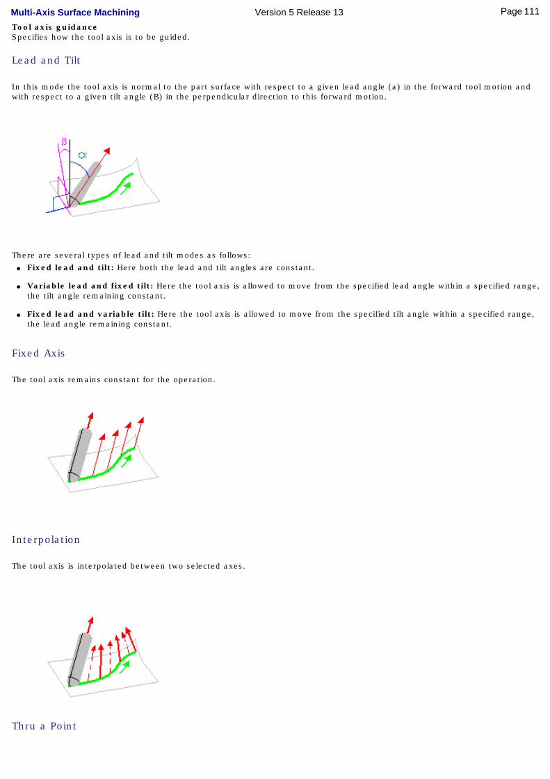
Tool axis guidanceSpecifies how the tool axis is to be guided.
Lead and Tilt
In this mode the tool axis is normal to the part surface with respect to a given lead angle (a) in the forward tool motion and with respect to a given tilt angle (B) in the perpendicular direction to this forward motion.
There are several types of lead and tilt modes as follows:● Fixed lead and tilt: Here both the lead and tilt angles are constant.
● Variable lead and fixed tilt: Here the tool axis is allowed to move from the specified lead angle within a specified range, the tilt angle remaining constant.
● Fixed lead and variable tilt: Here the tool axis is allowed to move from the specified tilt angle within a specified range, the lead angle remaining constant.
Fixed Axis
The tool axis remains constant for the operation.
Interpolation
The tool axis is interpolated between two selected axes.
Thru a Point
111Page Multi-Axis Surface Machining Version 5 Release 13

The tool axis passes through a specified point.
The tool axis can be oriented to point To or From the point.
Normal to Line
The tool axis passes through a specified curve, and is normal to this curve at all points. The tool axis can be oriented to point To or From the line.
Optimized Lead
The tool axis is allowed to vary from the specified lead angle within an allowed range. The allowed range is defined by Minimum and Maximum lead angles. The back of the cutter is to be kept clear of the part by means of a Minimum heel distance.
Optimized lead works as follows:● lead defined as minimum to fit the part curvature
● lead increases if necessary to respect the Minimum heel distance.
If the required lead is outside the allowed range, the tool position will not be kept in the tool path.
The maximum material removal is obtained when the tool curvature along the trajectory matches the part curvature.
4-axis Lead/Lag
112Page Multi-Axis Surface Machining Version 5 Release 13

The tool axis is normal to the part surface with respect to a given lead angle in the forward direction and is constrained to a specified plane.
The tool axis is computed like in Lead and Tilt mode and then projected into the constraint plane.
4-axis Tilt
The tool axis is normal to the part surface with respect to a given tilt angle and is constrained to a specified plane.
This is dedicated to milling parts with tool axis nearly parallel to the part itself (near flank milling).
This axis strategy is primary dedicated to NC machine whose configuration is A+C, but can be used on any other multi-axis machine. The figure below shows a machine with A and C axis on the table.
When A=C=0.00, the normal to the table is equal to the spindle orientation of the machine (which is fixed and equal to Z, there is no rotary axis on the head).On such a configuration, 4-axis Tilt strategy can be used to achieve a tool path in which the value of the A machine axis will be constant. Tool axis variation is provided by the C machine axis variation.
You are able to define the 4-axis constraint direction (that is, the direction in which tool axis component will be constant). In
113Page Multi-Axis Surface Machining Version 5 Release 13

the figure below, the highlight of the table shows that this direction has been defined by the normal to the table.
The Tilt angle is set to 45.00 degrees.
114Page Multi-Axis Surface Machining Version 5 Release 13

Lead angleSpecifies a user-defined incline of the tool axis in a plane defined by the direction of motion and the normal to the part surface. The lead angle is with respect to the part surface normal.
Maximum lead angleSpecifies a maximum lead angle.
Minimum lead angleSpecifies a minimum lead angle.
Tilt angleSpecifies a user-defined incline of the tool axis in a plane normal to the direction of motion. The tilt angle is with respect to the part surface normal. Allowed tiltSpecifies the range of allowed tilt variation. Minimum heel distanceAllows the back of the cutter to be kept clear of the part (for example, when machining a smooth concave ruled part with Optimized Lead tool axis guidance).
Multi-Axis Isoparametric Machining: Cutter Compensation Parameters
In the Machine Editor, the Compensation tab contains options for:
● globally defining the 3D contact cutter compensation mode: None/Contact/Tip and Contact
● imposing the compensation mode to all operations supporting the selected mode whatever the choice defined at machining operation level.
If the options are set as follows, compensation can be managed at machining operation level.
115Page Multi-Axis Surface Machining Version 5 Release 13
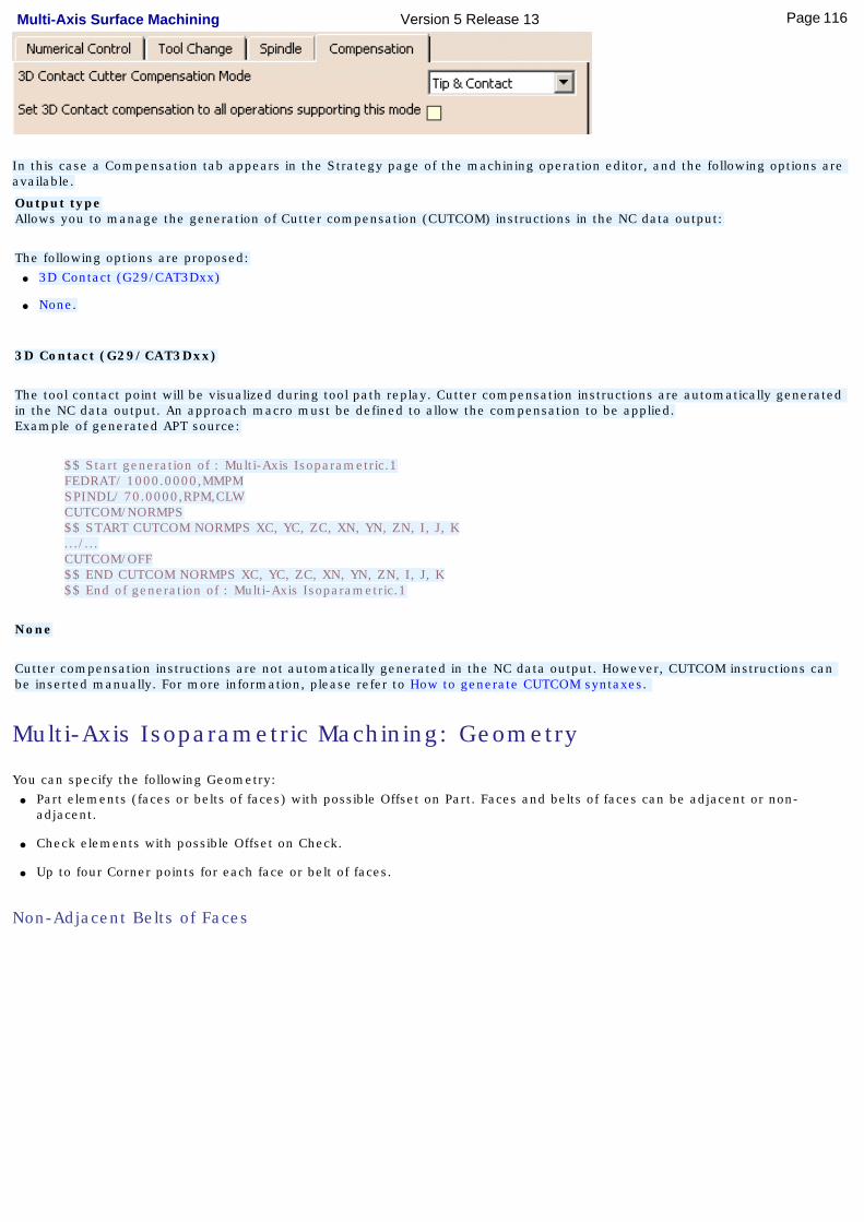
In this case a Compensation tab appears in the Strategy page of the machining operation editor, and the following options are available.
Output typeAllows you to manage the generation of Cutter compensation (CUTCOM) instructions in the NC data output:
The following options are proposed:● 3D Contact (G29/CAT3Dxx)
● None.
3D Contact (G29/CAT3Dxx)
The tool contact point will be visualized during tool path replay. Cutter compensation instructions are automatically generated in the NC data output. An approach macro must be defined to allow the compensation to be applied.Example of generated APT source:
$$ Start generation of : Multi-Axis Isoparametric.1FEDRAT/ 1000.0000,MMPMSPINDL/ 70.0000,RPM,CLWCUTCOM/NORMPS$$ START CUTCOM NORMPS XC, YC, ZC, XN, YN, ZN, I, J, K.../...CUTCOM/OFF$$ END CUTCOM NORMPS XC, YC, ZC, XN, YN, ZN, I, J, K$$ End of generation of : Multi-Axis Isoparametric.1
None
Cutter compensation instructions are not automatically generated in the NC data output. However, CUTCOM instructions can be inserted manually. For more information, please refer to How to generate CUTCOM syntaxes.
Multi-Axis Isoparametric Machining: Geometry
You can specify the following Geometry:● Part elements (faces or belts of faces) with possible Offset on Part. Faces and belts of faces can be adjacent or non-
adjacent.
● Check elements with possible Offset on Check.
● Up to four Corner points for each face or belt of faces.
Non-Adjacent Belts of Faces
116Page Multi-Axis Surface Machining Version 5 Release 13
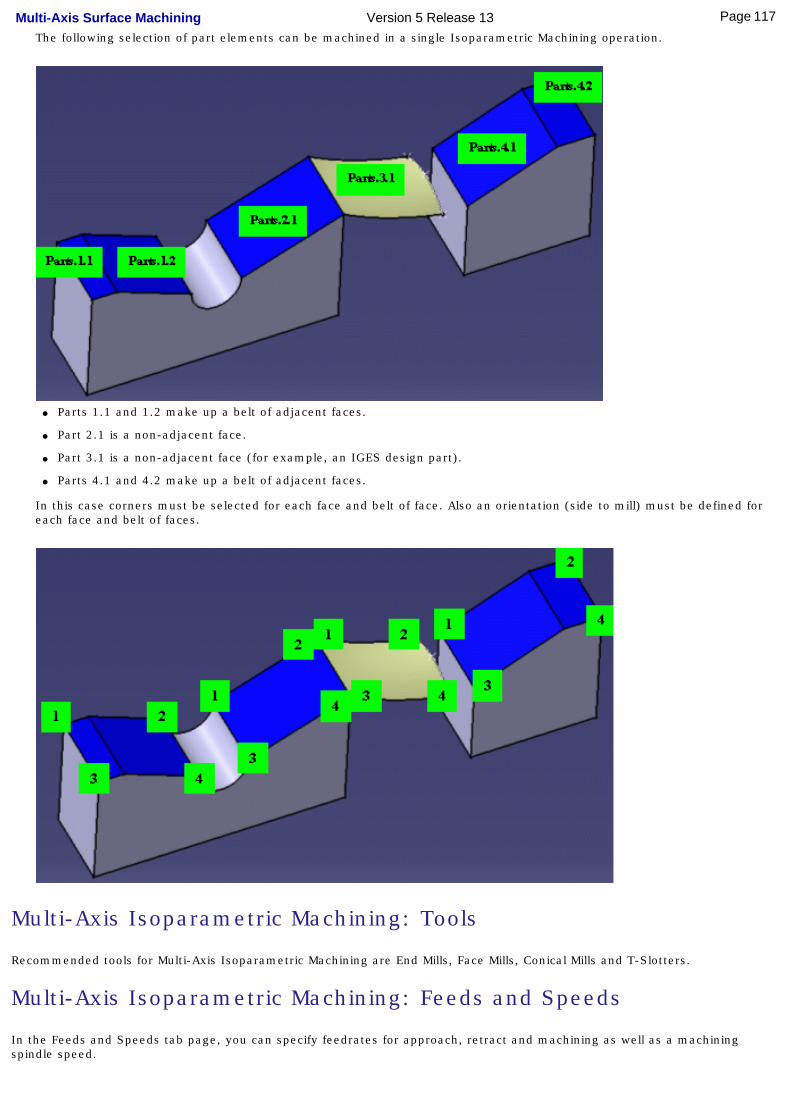
The following selection of part elements can be machined in a single Isoparametric Machining operation.
● Parts 1.1 and 1.2 make up a belt of adjacent faces.
● Part 2.1 is a non-adjacent face.
● Part 3.1 is a non-adjacent face (for example, an IGES design part).
● Parts 4.1 and 4.2 make up a belt of adjacent faces.
In this case corners must be selected for each face and belt of face. Also an orientation (side to mill) must be defined for each face and belt of faces.
Multi-Axis Isoparametric Machining: Tools
Recommended tools for Multi-Axis Isoparametric Machining are End Mills, Face Mills, Conical Mills and T-Slotters.
Multi-Axis Isoparametric Machining: Feeds and Speeds
In the Feeds and Speeds tab page, you can specify feedrates for approach, retract and machining as well as a machining spindle speed.
117Page Multi-Axis Surface Machining Version 5 Release 13

Feedrates and spindle speed can be defined in linear or angular units.
A Spindle output checkbox is available for managing output the SPINDL instruction in the generated NC data file. If the checkbox is selected, the instruction is generated. Otherwise, it is not generated.
Feeds and speeds of the operation can be updated automatically according to tooling data and the Rough or Finish quality of the operation. This is described in Update of Feeds and Speeds on Machining Operation.
Multi-Axis Isoparametric Machining: NC Macros
You can define transition paths in your machining operations by means of NC Macros. These transition paths are useful for providing approach, retract, return, and linking motion in the tool path.
An Approach macro is used to approach the operation start point.
A Retract macro is used to retract from the operation end point.
A Linking macro may be to link two non consecutive paths, for example. It comprises an approach and a retract path.
A Return in a Level macro is used in a multi-path operation to link two consecutive paths in a given level. It comprises an approach and a retract path.
A Clearance macro can be used in a machining operation to avoid a fixture, for example.
118Page Multi-Axis Surface Machining Version 5 Release 13
Multi-Axis Contour Driven The information in this section will help you create and manage Multi-Axis Contour Driven operations in your NC manufacturing program.
To create a Multi-Axis Contour Driven operation, select the icon and select the geometry to be
machined .
Select the machining strategy tab and choose a guiding strategy for this operation:
● Between contours
● Parallel contours
● Spine contour.
Depending on the chosen strategy, select the necessary guiding elements.
Then set the following strategy parameters according to the desired machining:● machining criteria
● stepover conditions
● tool axis guidance
● cutter compensation.
Specify the tool to be used, feeds and speeds , and NC macros as needed.
Multi-Axis Contour Driven: Strategy Parameters
Multi-Axis Contour Driven: Machining ParametersTool path styleIndicates the cutting mode of the operation:
● Zig Zag: the machining direction is reversed from one path to the next
● One way: the same machining direction is used from one path to the next.
Machining toleranceSpecifies the maximum allowed distance between the theoretical and computed tool path. Maximum discretization stepEnsures linearity between points that are far apart. Maximum discretization angleSpecifies the maximum angular change of tool axis between tool positions. It is used to add more tool positions (points and axis) if value is exceeded. Minimum path lengthSpecifies the minimum length that a path needs to have to be taken into account.
Multi-Axis Contour Driven: Stepover Parameters
119Page Multi-Axis Surface Machining Version 5 Release 13
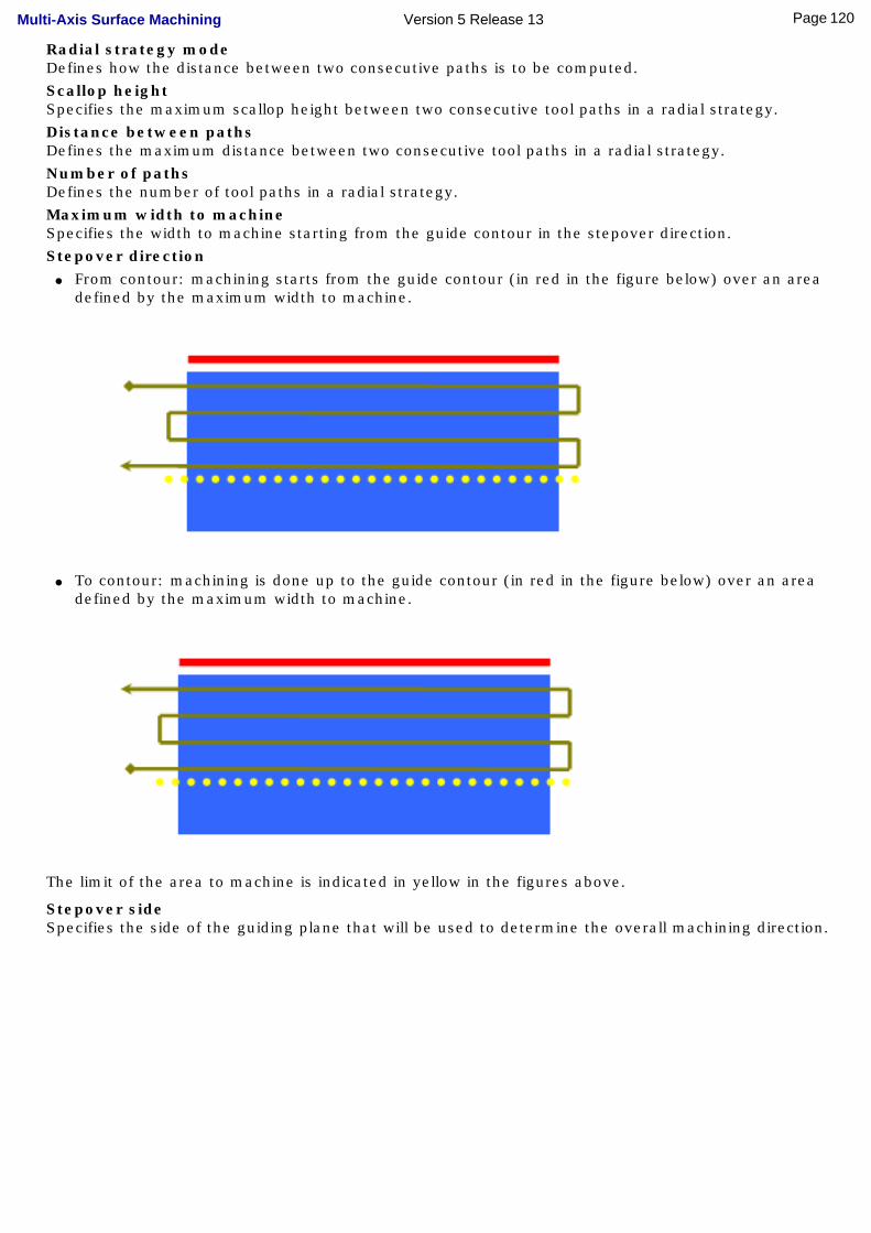
Radial strategy modeDefines how the distance between two consecutive paths is to be computed. Scallop heightSpecifies the maximum scallop height between two consecutive tool paths in a radial strategy. Distance between pathsDefines the maximum distance between two consecutive tool paths in a radial strategy. Number of pathsDefines the number of tool paths in a radial strategy. Maximum width to machineSpecifies the width to machine starting from the guide contour in the stepover direction. Stepover direction
● From contour: machining starts from the guide contour (in red in the figure below) over an area defined by the maximum width to machine.
● To contour: machining is done up to the guide contour (in red in the figure below) over an area defined by the maximum width to machine.
The limit of the area to machine is indicated in yellow in the figures above.
Stepover sideSpecifies the side of the guiding plane that will be used to determine the overall machining direction.
120Page Multi-Axis Surface Machining Version 5 Release 13
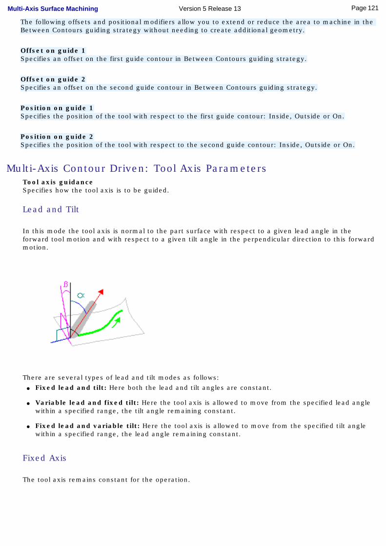
The following offsets and positional modifiers allow you to extend or reduce the area to machine in the Between Contours guiding strategy without needing to create additional geometry.
Offset on guide 1Specifies an offset on the first guide contour in Between Contours guiding strategy.
Offset on guide 2Specifies an offset on the second guide contour in Between Contours guiding strategy.
Position on guide 1Specifies the position of the tool with respect to the first guide contour: Inside, Outside or On.
Position on guide 2Specifies the position of the tool with respect to the second guide contour: Inside, Outside or On.
Multi-Axis Contour Driven: Tool Axis ParametersTool axis guidanceSpecifies how the tool axis is to be guided.
Lead and Tilt
In this mode the tool axis is normal to the part surface with respect to a given lead angle in the forward tool motion and with respect to a given tilt angle in the perpendicular direction to this forward motion.
There are several types of lead and tilt modes as follows:● Fixed lead and tilt: Here both the lead and tilt angles are constant.
● Variable lead and fixed tilt: Here the tool axis is allowed to move from the specified lead angle within a specified range, the tilt angle remaining constant.
● Fixed lead and variable tilt: Here the tool axis is allowed to move from the specified tilt angle within a specified range, the lead angle remaining constant.
Fixed Axis
The tool axis remains constant for the operation.
121Page Multi-Axis Surface Machining Version 5 Release 13

Thru a Point
The tool axis passes through a specified point. The tool axis can be oriented to point To or From the point.
Normal to Line
The tool axis passes through a specified curve, and is normal to this curve at all points. The tool axis can be oriented to point To or From the line.
Optimized Lead
he tool axis is allowed to vary from the specified lead angle within an allowed range. The allowed range is defined by Minimum and Maximum lead angles. The back of the cutter is to be kept clear of the part by means of a Minimum heel distance.
122Page Multi-Axis Surface Machining Version 5 Release 13

Optimized lead works as follows:● lead defined as minimum to fit the part curvature
● lead increases if necessary to respect the Minimum heel distance.
If the required lead is outside the allowed range, the tool position will not be kept in the tool path.
The maximum material removal is obtained when the tool curvature along the trajectory matches the part curvature.
4-axis Lead/Lag
The tool axis is normal to the part surface with respect to a given lead angle in the forward direction and is constrained to a specified plane.
The tool axis is computed like in Lead and Tilt mode and then projected into the constraint plane.
Lead angleSpecifies a user-defined incline of the tool axis in a plane defined by the direction of motion and the normal to the part surface. The lead angle is with respect to the part surface normal.
Maximum lead angleSpecifies a maximum lead angle.
Minimum lead angleSpecifies a minimum lead angle.
Tilt angleSpecifies a user-defined incline of the tool axis in a plane normal to the direction of motion. The tilt angle is with respect to the part surface normal.
123Page Multi-Axis Surface Machining Version 5 Release 13
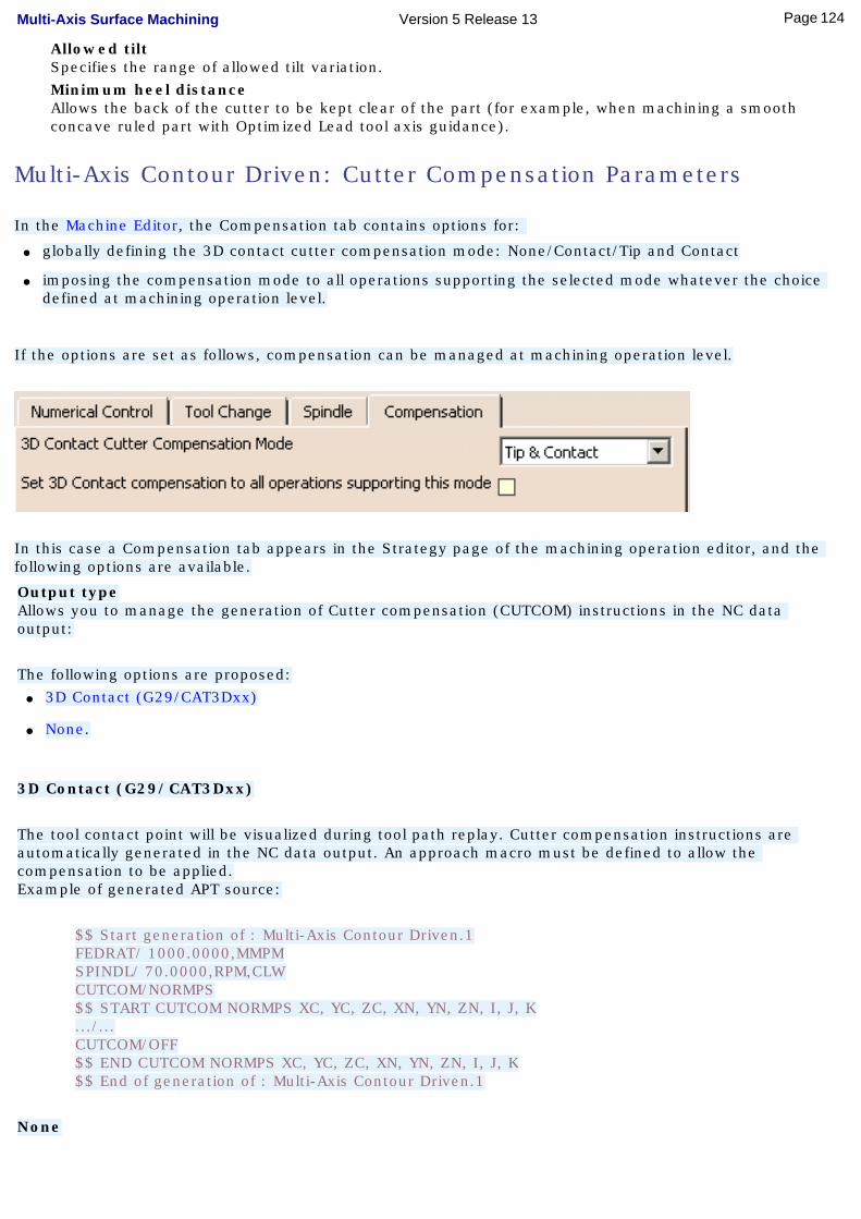
Allowed tiltSpecifies the range of allowed tilt variation. Minimum heel distanceAllows the back of the cutter to be kept clear of the part (for example, when machining a smooth concave ruled part with Optimized Lead tool axis guidance).
Multi-Axis Contour Driven: Cutter Compensation Parameters
In the Machine Editor, the Compensation tab contains options for:
● globally defining the 3D contact cutter compensation mode: None/Contact/Tip and Contact
● imposing the compensation mode to all operations supporting the selected mode whatever the choice defined at machining operation level.
If the options are set as follows, compensation can be managed at machining operation level.
In this case a Compensation tab appears in the Strategy page of the machining operation editor, and the following options are available.
Output typeAllows you to manage the generation of Cutter compensation (CUTCOM) instructions in the NC data output:
The following options are proposed:● 3D Contact (G29/CAT3Dxx)
● None.
3D Contact (G29/CAT3Dxx)
The tool contact point will be visualized during tool path replay. Cutter compensation instructions are automatically generated in the NC data output. An approach macro must be defined to allow the compensation to be applied.Example of generated APT source:
$$ Start generation of : Multi-Axis Contour Driven.1FEDRAT/ 1000.0000,MMPMSPINDL/ 70.0000,RPM,CLWCUTCOM/NORMPS$$ START CUTCOM NORMPS XC, YC, ZC, XN, YN, ZN, I, J, K.../...CUTCOM/OFF$$ END CUTCOM NORMPS XC, YC, ZC, XN, YN, ZN, I, J, K$$ End of generation of : Multi-Axis Contour Driven.1
None
124Page Multi-Axis Surface Machining Version 5 Release 13
Cutter compensation instructions are not automatically generated in the NC data output. However, CUTCOM instructions can be inserted manually. For more information, please refer to How to generate CUTCOM syntaxes.
Multi-Axis Contour Driven: Geometry
You can specify the following Geometry:● Part with possible Offset on Part.
❍ For Between Contours strategy, the area to machine on the selected part is determined by selecting two guide curves and two limit curves. Tool paths are parallel to the selected guide curves.
❍ For Parallel Contours strategy, the area to machine on the selected part is determined by selecting a guide curve specifying a maximum width to machine. Tool paths are parallel to the spine curve.
❍ For Spine Contour strategy, the area to machine on the selected part is determined by selecting a spine curve. Tool paths are perpendicular to the spine curve.
● Check elements with possible Offset on Check.
● Areas to avoid.
● Limiting Contour, which defines the limit for machining on the part.
You can use Offset Groups and Features when defining geometry.
Multi-Axis Contour Driven: Tools
Recommended tools for Multi-Axis Contour Driven are End Mills, Face Mills, Conical Mills and T-Slotters.
Multi-Axis Contour Driven: Feeds and Speeds
In the Feeds and Speeds tab page, you can specify feedrates for approach, retract and machining as well as a machining spindle speed.
Feedrates and spindle speed can be defined in linear or angular units.
A Spindle output checkbox is available for managing output the SPINDL instruction in the generated NC data file. If the checkbox is selected, the instruction is generated. Otherwise, it is not generated.
Feeds and speeds of the operation can be updated automatically according to tooling data and the Rough or Finish quality of the operation. This is described in Update of Feeds and Speeds on Machining Operation.
Multi-Axis Contour Driven: NC Macros
You can define transition paths in your machining operations by means of NC Macros. These transition paths are useful for providing approach, retract, return, and linking motion in the tool path.
An Approach macro is used to approach the operation start point.
A Retract macro is used to retract from the operation end point.
125Page Multi-Axis Surface Machining Version 5 Release 13

A Linking macro may be to link two non consecutive paths, for example. It comprises an approach and a retract path.
A Return in a Level macro is used in a multi-path operation to link two consecutive paths in a given level. It comprises an approach and a retract path.
A Clearance macro can be used in a machining operation to avoid a fixture, for example.
126Page Multi-Axis Surface Machining Version 5 Release 13
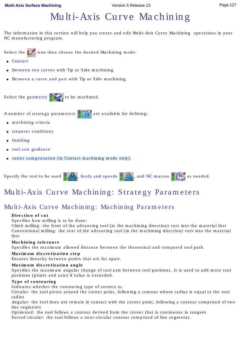
Multi-Axis Curve MachiningThe information in this section will help you create and edit Multi-Axis Curve Machining operations in your NC manufacturing program.
Select the icon then choose the desired Machining mode:
● Contact
● Between two curves with Tip or Side machining
● Between a curve and part with Tip or Side machining.
Select the geometry to be machined.
A number of strategy parameters are available for defining:
● machining criteria
● stepover conditions
● finishing
● tool axis guidance
● cutter compensation (in Contact machining mode only).
Specify the tool to be used , feeds and speeds , and NC macros as needed.
Multi-Axis Curve Machining: Strategy Parameters
Multi-Axis Curve Machining: Machining ParametersDirection of cutSpecifies how milling is to be done: Climb milling: the front of the advancing tool (in the machining direction) cuts into the material firstConventional milling: the rear of the advancing tool (in the machining direction) cuts into the material firstMachining toleranceSpecifies the maximum allowed distance between the theoretical and computed tool path. Maximum discretization stepEnsures linearity between points that are far apart. Maximum discretization angleSpecifies the maximum angular change of tool axis between tool positions. It is used to add more tool positions (points and axis) if value is exceeded. Type of contouringIndicates whether the contouring type of corners is: Circular: the tool pivots around the corner point, following a contour whose radius is equal to the tool radiusAngular: the tool does not remain in contact with the corner point, following a contour comprised of two line segmentsOptimized: the tool follows a contour derived from the corner that is continuous in tangentForced circular: the tool follows a near-circular contour comprised of line segments.
127Page Multi-Axis Surface Machining Version 5 Release 13
Forced contourSpecifies whether the contour is to be forced open or closed. Closed contour overlapSpecifies the percentage overlap on the closed contour.
Multi-Axis Curve Machining: Stepover ParametersTool path styleIndicates the cutting mode of the operation: Zig Zag: the machining direction is reversed from one path to the nextOne way: the same machining direction is used from one path to the next.SequencingSpecifies the order in which machining is to be done: Axial: axial machining is done first then radialRadial: radial machining is done first then axial.Distance between pathsDefines the maximum distance between two consecutive tool paths in a radial strategy. Number of pathsDefines the number of tool paths in a radial strategy. Axial strategy modeDefines how the distance between two consecutive levels is to be computed. Maximum depth of cutDefines the maximum depth of cut in an axial strategy. Number of levelsDefines the number of levels to be machined in an axial strategy.
Multi-Axis Curve Machining: Finishing ParametersFinishing modeIndicates whether or not finish passes are to be generated on the sides and bottom of the area to machine. Side finishing can be done at each level or only at the last level of the operation. Side finish thicknessSpecifies the thickness used for side finishing. Side finish thickness on bottomSpecifies the thickness used for the last side finish pass at the end of the operation. Bottom finish thicknessSpecifies the thickness used for bottom finishing. Bottom finish path styleDefines the bottom finish path style: Zig zag or One way. Spring passIndicates whether or not a spring pass is to be generated on the sides in the same condition as the previous Side finish pass. The spring pass is used to compensate the natural `spring' of the tool.
Multi-Axis Curve Machining: Tool Axis Parameters
128Page Multi-Axis Surface Machining Version 5 Release 13

Tool axis guidanceSpecifies how the tool axis is to be guided.
Lead and Tilt
For Contact machining, the tool axis is normal to the part surface with respect to a given lead angle in the forward tool motion and with respect to a given tilt angle in the perpendicular direction to this forward motion.
For Tip and Side machining, the tool axis is normal to the guides with respect to a given lead angle in the forward tool motion and with respect to a given tilt angle in the perpendicular direction to this forward motion.
There are several types of lead and tilt modes as follows:Fixed lead and tilt: Here both the lead and tilt angles are constant.Variable lead and fixed tilt: Here the tool axis is allowed to move from the specified lead angle within a specified range, the tilt angle remaining constant.Fixed lead and variable tilt: Here the tool axis is allowed to move from the specified tilt angle within a specified range, the lead angle remaining constant.
Fixed Axis
The tool axis remains constant for the operation.
Interpolation
The tool axis is interpolated between two selected axes.
129Page Multi-Axis Surface Machining Version 5 Release 13
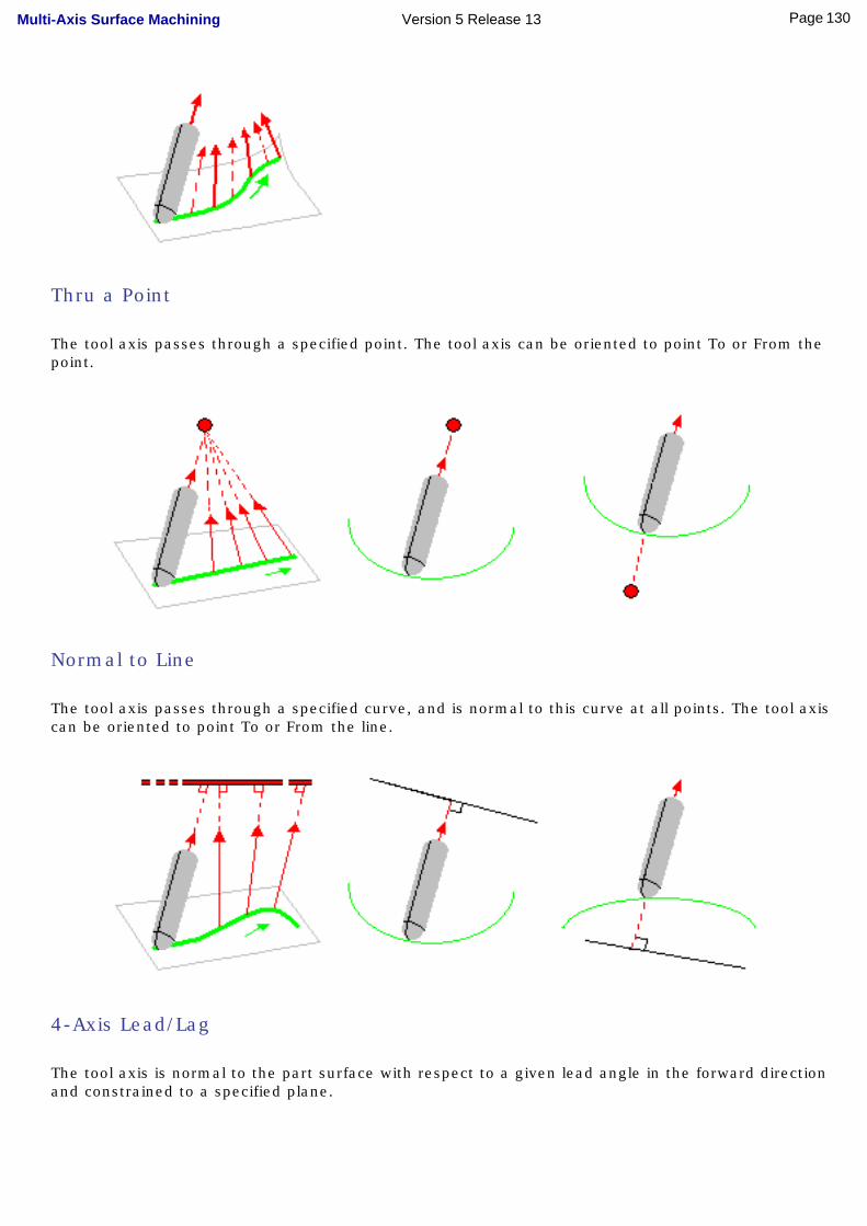
Thru a Point
The tool axis passes through a specified point. The tool axis can be oriented to point To or From the point.
Normal to Line
The tool axis passes through a specified curve, and is normal to this curve at all points. The tool axis can be oriented to point To or From the line.
4-Axis Lead/Lag
The tool axis is normal to the part surface with respect to a given lead angle in the forward direction and constrained to a specified plane.
130Page Multi-Axis Surface Machining Version 5 Release 13

The tool axis is computed like in Lead and Tilt mode and then projected into the constraint plane.
Optimized Lead
For Contact machining only. The tool axis is allowed to vary from the specified lead angle within an allowed range. The allowed range is defined by Minimum and Maximum lead angles. The back of the cutter is to be kept clear of the part by means of a Minimum heel distance.
Optimized lead works as follows:● lead defined as minimum to fit the part curvature
● lead increases if necessary to respect the Minimum heel distance.
If the required lead is outside the allowed range, the tool position will not be kept in the tool path.
The maximum material removal is obtained when the tool curvature along the trajectory matches the part curvature.
Tangent Axis
Tangent Axis guidance is available for Between Two Curves and Between Curve and Part machining modes only. Note that a cylindrical tool should be used.
The Tangent Axis modes are as follows:● Along ruling direction
Dedicated to milling walls made of a set (strip) of ruled and developable surfaces (possibly with some planar ones), by mapping the tool axis to the ruling direction of the drive surfaces. Maximum material removal is obtained when ruling direction on drive surface matches the ruling direction on tool.
131Page Multi-Axis Surface Machining Version 5 Release 13
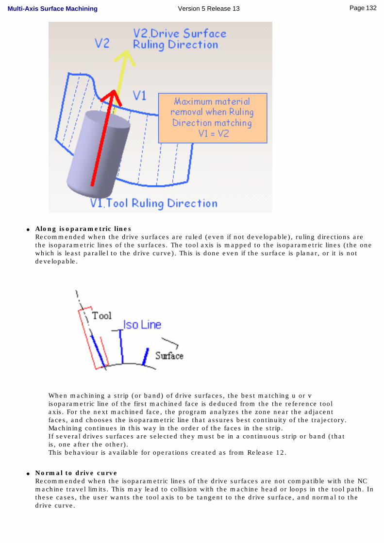
● Along isoparametric linesRecommended when the drive surfaces are ruled (even if not developable), ruling directions are the isoparametric lines of the surfaces. The tool axis is mapped to the isoparametric lines (the one which is least parallel to the drive curve). This is done even if the surface is planar, or it is not developable.
When machining a strip (or band) of drive surfaces, the best matching u or v isoparametric line of the first machined face is deduced from the the reference tool axis. For the next machined face, the program analyzes the zone near the adjacent faces, and chooses the isoparametric line that assures best continuity of the trajectory. Machining continues in this way in the order of the faces in the strip.If several drives surfaces are selected they must be in a continuous strip or band (that is, one after the other). This behaviour is available for operations created as from Release 12.
● Normal to drive curveRecommended when the isoparametric lines of the drive surfaces are not compatible with the NC machine travel limits. This may lead to collision with the machine head or loops in the tool path. In these cases, the user wants the tool axis to be tangent to the drive surface, and normal to the drive curve.
132Page Multi-Axis Surface Machining Version 5 Release 13
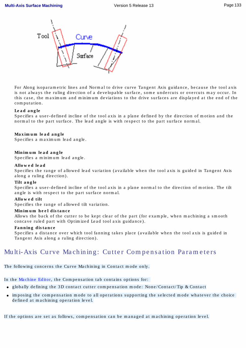
For Along isoparametric lines and Normal to drive curve Tangent Axis guidance, because the tool axis is not always the ruling direction of a developable surface, some undercuts or overcuts may occur. In this case, the maximum and minimum deviations to the drive surfaces are displayed at the end of the computation.
Lead angleSpecifies a user-defined incline of the tool axis in a plane defined by the direction of motion and the normal to the part surface. The lead angle is with respect to the part surface normal.
Maximum lead angleSpecifies a maximum lead angle.
Minimum lead angleSpecifies a minimum lead angle.
Allowed leadSpecifies the range of allowed lead variation (available when the tool axis is guided in Tangent Axis along a ruling direction). Tilt angleSpecifies a user-defined incline of the tool axis in a plane normal to the direction of motion. The tilt angle is with respect to the part surface normal. Allowed tiltSpecifies the range of allowed tilt variation. Minimum heel distanceAllows the back of the cutter to be kept clear of the part (for example, when machining a smooth concave ruled part with Optimized Lead tool axis guidance). Fanning distanceSpecifies a distance over which tool fanning takes place (available when the tool axis is guided in Tangent Axis along a ruling direction).
Multi-Axis Curve Machining: Cutter Compensation Parameters
The following concerns the Curve Machining in Contact mode only.
In the Machine Editor, the Compensation tab contains options for:
● globally defining the 3D contact cutter compensation mode: None/Contact/Tip & Contact
● imposing the compensation mode to all operations supporting the selected mode whatever the choice defined at machining operation level.
If the options are set as follows, compensation can be managed at machining operation level.
133Page Multi-Axis Surface Machining Version 5 Release 13
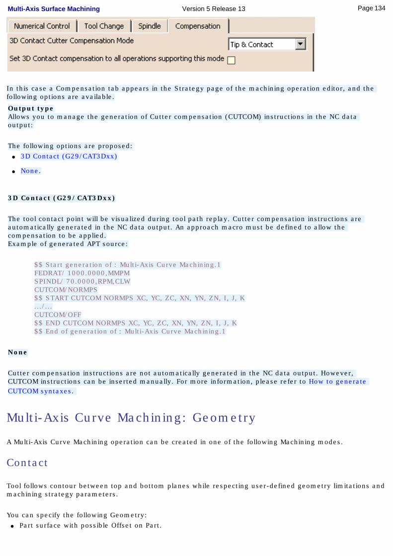
In this case a Compensation tab appears in the Strategy page of the machining operation editor, and the following options are available.
Output typeAllows you to manage the generation of Cutter compensation (CUTCOM) instructions in the NC data output:
The following options are proposed:● 3D Contact (G29/CAT3Dxx)
● None.
3D Contact (G29/CAT3Dxx)
The tool contact point will be visualized during tool path replay. Cutter compensation instructions are automatically generated in the NC data output. An approach macro must be defined to allow the compensation to be applied.Example of generated APT source:
$$ Start generation of : Multi-Axis Curve Machining.1FEDRAT/ 1000.0000,MMPMSPINDL/ 70.0000,RPM,CLWCUTCOM/NORMPS$$ START CUTCOM NORMPS XC, YC, ZC, XN, YN, ZN, I, J, K.../...CUTCOM/OFF$$ END CUTCOM NORMPS XC, YC, ZC, XN, YN, ZN, I, J, K$$ End of generation of : Multi-Axis Curve Machining.1
None
Cutter compensation instructions are not automatically generated in the NC data output. However, CUTCOM instructions can be inserted manually. For more information, please refer to How to generate CUTCOM syntaxes.
Multi-Axis Curve Machining: Geometry
A Multi-Axis Curve Machining operation can be created in one of the following Machining modes.
Contact
Tool follows contour between top and bottom planes while respecting user-defined geometry limitations and machining strategy parameters.
You can specify the following Geometry:● Part surface with possible Offset on Part.
134Page Multi-Axis Surface Machining Version 5 Release 13
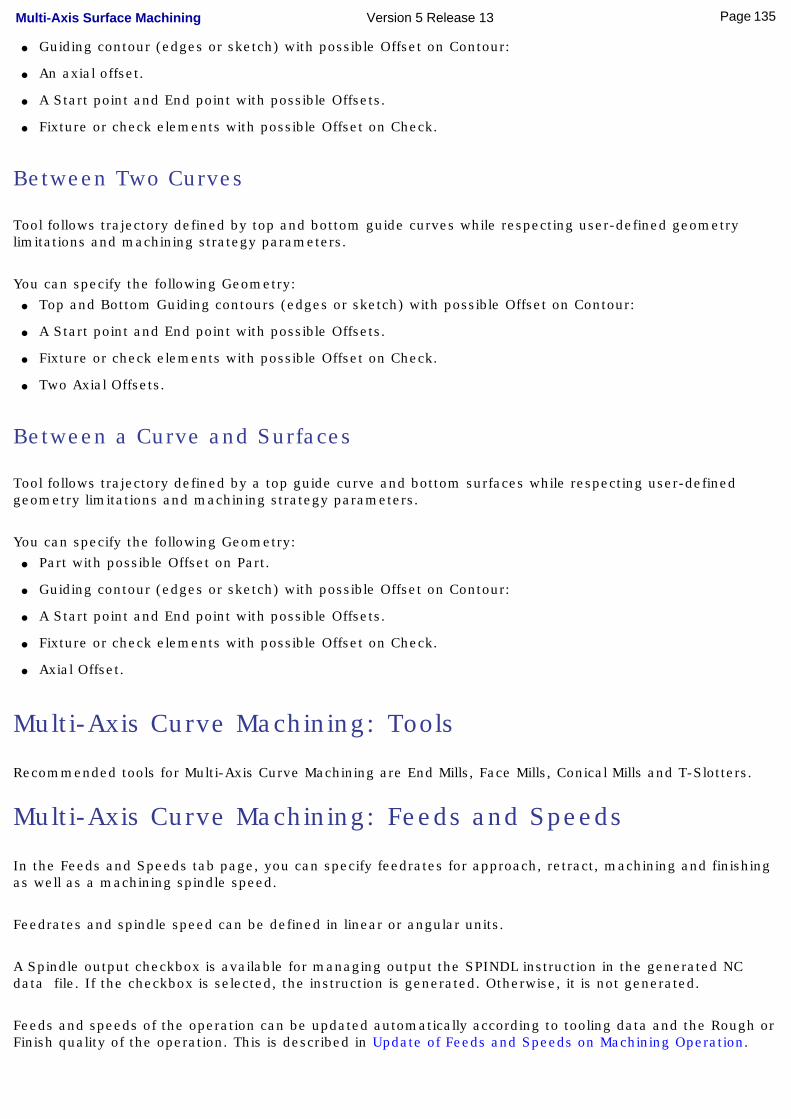
● Guiding contour (edges or sketch) with possible Offset on Contour:
● An axial offset.
● A Start point and End point with possible Offsets.
● Fixture or check elements with possible Offset on Check.
Between Two Curves
Tool follows trajectory defined by top and bottom guide curves while respecting user-defined geometry limitations and machining strategy parameters.
You can specify the following Geometry:● Top and Bottom Guiding contours (edges or sketch) with possible Offset on Contour:
● A Start point and End point with possible Offsets.
● Fixture or check elements with possible Offset on Check.
● Two Axial Offsets.
Between a Curve and Surfaces
Tool follows trajectory defined by a top guide curve and bottom surfaces while respecting user-defined geometry limitations and machining strategy parameters.
You can specify the following Geometry:● Part with possible Offset on Part.
● Guiding contour (edges or sketch) with possible Offset on Contour:
● A Start point and End point with possible Offsets.
● Fixture or check elements with possible Offset on Check.
● Axial Offset.
Multi-Axis Curve Machining: Tools
Recommended tools for Multi-Axis Curve Machining are End Mills, Face Mills, Conical Mills and T-Slotters.
Multi-Axis Curve Machining: Feeds and Speeds
In the Feeds and Speeds tab page, you can specify feedrates for approach, retract, machining and finishing as well as a machining spindle speed.
Feedrates and spindle speed can be defined in linear or angular units.
A Spindle output checkbox is available for managing output the SPINDL instruction in the generated NC data file. If the checkbox is selected, the instruction is generated. Otherwise, it is not generated.
Feeds and speeds of the operation can be updated automatically according to tooling data and the Rough or Finish quality of the operation. This is described in Update of Feeds and Speeds on Machining Operation.
135Page Multi-Axis Surface Machining Version 5 Release 13
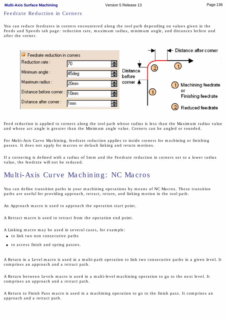
Feedrate Reduction in Corners
You can reduce feedrates in corners encountered along the tool path depending on values given in the Feeds and Speeds tab page: reduction rate, maximum radius, minimum angle, and distances before and after the corner.
Feed reduction is applied to corners along the tool path whose radius is less than the Maximum radius value and whose arc angle is greater than the Minimum angle value. Corners can be angled or rounded.
For Multi-Axis Curve Machining, feedrate reduction applies to inside corners for machining or finishing passes. It does not apply for macros or default linking and return motions.
If a cornering is defined with a radius of 5mm and the Feedrate reduction in corners set to a lower radius value, the feedrate will not be reduced.
Multi-Axis Curve Machining: NC Macros
You can define transition paths in your machining operations by means of NC Macros. These transition paths are useful for providing approach, retract, return, and linking motion in the tool path.
An Approach macro is used to approach the operation start point.
A Retract macro is used to retract from the operation end point.
A Linking macro may be used in several cases, for example: ● to link two non consecutive paths
● to access finish and spring passes.
A Return in a Level macro is used in a multi-path operation to link two consecutive paths in a given level. It comprises an approach and a retract path.
A Return between Levels macro is used in a multi-level machining operation to go to the next level. It comprises an approach and a retract path.
A Return to Finish Pass macro is used in a machining operation to go to the finish pass. It comprises an approach and a retract path.
136Page Multi-Axis Surface Machining Version 5 Release 13

A Clearance macro can be used in a machining operation to avoid a fixture, for example.
137Page Multi-Axis Surface Machining Version 5 Release 13
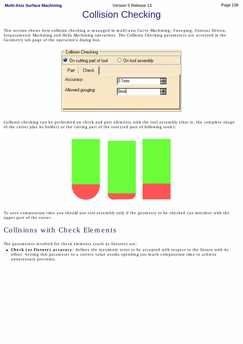
Collision CheckingThis section shows how collision checking is managed in multi-axis Curve Machining, Sweeping, Contour Driven, Isoparametric Machining and Helix Machining operations. The Collision Checking parameters are accessed in the Geometry tab page of the operation's dialog box.
Collision checking can be performed on check and part elements with the tool assembly (that is, the complete shape of the cutter plus its holder) or the cutting part of the tool (red part of following tools):
To save computation time you should use tool assembly only if the geometry to be checked can interfere with the upper part of the cutter.
Collisions with Check Elements
The parameters involved for check elements (such as fixtures) are:● Check (or Fixture) accuracy: defines the maximum error to be accepted with respect to the fixture with its
offset. Setting this parameter to a correct value avoids spending too much computation time to achieve unnecessary precision.
138Page Multi-Axis Surface Machining Version 5 Release 13

● Offset on check: minimum distance between the cutter and the fixture, used to limit the tool path.
● Allowed gouging: maximum cutter interference with the fixture during "linking passes" (including approach and retract motion).
This illustration shows return motion with no macro or jump.
139Page Multi-Axis Surface Machining Version 5 Release 13
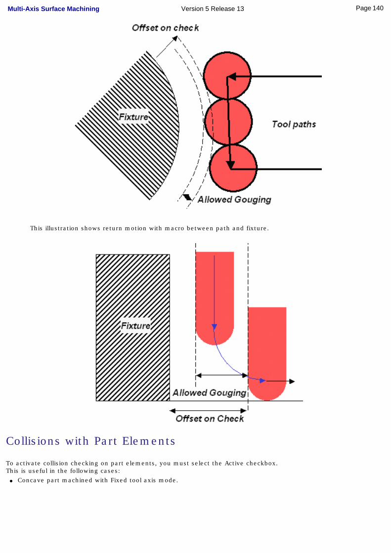
This illustration shows return motion with macro between path and fixture.
Collisions with Part Elements
To activate collision checking on part elements, you must select the Active checkbox. This is useful in the following cases:
● Concave part machined with Fixed tool axis mode.
140Page Multi-Axis Surface Machining Version 5 Release 13
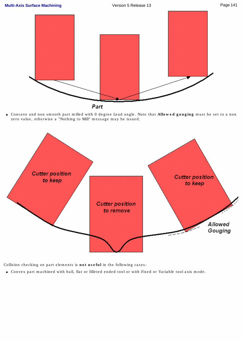
● Concave and non smooth part milled with 0 degree Lead angle. Note that Allowed gouging must be set to a non zero value, otherwise a "Nothing to Mill" message may be issued.
Collision checking on part elements is not useful in the following cases:
● Convex part machined with ball, flat or filleted ended tool or with Fixed or Variable tool axis mode.
141Page Multi-Axis Surface Machining Version 5 Release 13
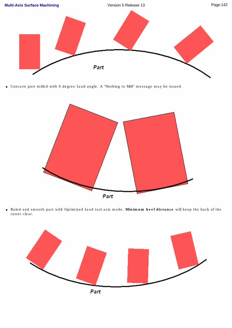
● Concave part milled with 0 degree Lead angle. A "Nothing to Mill" message may be issued.
● Ruled and smooth part with Optimized Lead tool axis mode. Minimum heel distance will keep the back of the cutter clear.
142Page Multi-Axis Surface Machining Version 5 Release 13
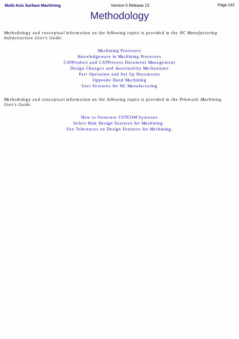
MethodologyMethodology and conceptual information on the following topics is provided in the NC Manufacturing Infrastructure User's Guide.
Machining ProcessesKnowledgeware in Machining Processes
CATProduct and CATProcess Document ManagementDesign Changes and Associativity Mechanisms
Part Operation and Set Up DocumentsOpposite Hand Machining
User Features for NC Manufacturing
Methodology and conceptual information on the following topics is provided in the Prismatic Machining User's Guide.
How to Generate CUTCOM SyntaxesSelect Hole Design Features for Machining
Use Tolerances on Design Features for Machining.
143Page Multi-Axis Surface Machining Version 5 Release 13

Glossary
Aapproach macro
Motion defined for approaching the operation start point
auxiliary command
A control function such as tool change or machine table rotation. These commands may be interpreted by a specific post-processor.
axial machining operation
Operation in which machining is done along a single axis and is mainly intended for hole making (drilling, counter boring, and so on).
Bback and forth Machining in which motion is done alternately in one direction then the other. Compare
with one way.
Between Contours mode
Machining mode of a Contour Driven operation in which the tool follows a Zig zag or One way trajectory between two user defined curves.
bottom plane A planar geometric element that represents the bottom surface of an area to machine. It is normal to the tool axis.
C clearance macro
Motion that involves retracting to a safety plane, a linear trajectory in that plane and then plunging from that plane.
climb milling Milling in which the advancing tool rotates down into the material. Chips of cut material tend to be thrown behind the tool, which results in good surface finish. Compare with conventional milling.
conventional milling
Milling in which the advancing tool rotates up into the material. Chips of cut material tend to be carried around with the tool, which often impairs good surface finish. Compare with climb milling.
DDPM Digital Process for Manufacturing.
Eextension type
Defines the end type of a hole as being through hole or blind.
FFault Types of faults in material removal simulation are gouge, undercut, and tool clash.
144Page Multi-Axis Surface Machining Version 5 Release 13

feedrate Rate at which a cutter advances into a work piece. Measured in linear or angular units (mm/min or mm/rev, for example).
fixture Elements used to secure or support the workpiece on a machine.
Ggouge Area where the tool has removed too much material from the workpiece.
guiding plane In sweeping operations, this plane is deduced from the view and starting directions. Machining is done in planes parallel to the guiding plane. The tool contact point is guided by this plane during machining.
Hhard A geometric element (such as a boundary or a bottom face) that the tool cannot pass
beyond.
Llead angle User-defined incline of the tool axis in a plane defined by the direction of motion and the
normal to the part surface. The tool axis incline is with respect to the part surface normal. Compare with tilt angle.
linking motion Motion that involves retracting to a safety plane, a linear trajectory in that plane and then plunging from that plane.
Mmachine rotation
An auxiliary command in the program that corresponds to a rotation of the machine table.
machining axis system
Reference axis system in which coordinates of points of the tool path are given.
machining feature
A feature instance representing a volume of material to be removed, a machining axis, tolerances, and other technological attributes. These features may be hole type or milling type.
machining operation
Contains all the necessary information for machining a part of the workpiece using a single tool.
Machining tolerance
The maximum allowed difference between the theoretical and computed tool path.
manufacturing process
Defines the sequence of part operations necessary for the complete manufacture of a part.
manufacturing program
Describes the processing order of the NC entities that are taken into account for tool path computation: machining operations, auxiliary commands and PP instructions.
manufacturing view
The set of machining features defined in the part operation.
Multi-axis Contour Driven
A milling operation in which the tool is driven along a contour while respecting user-defined geometric limitations and machining strategy parameters. Three machining modes are Parallel Contours, Between Contours and Spine Contour. A number of tool axis guidance modes are available.
145Page Multi-Axis Surface Machining Version 5 Release 13
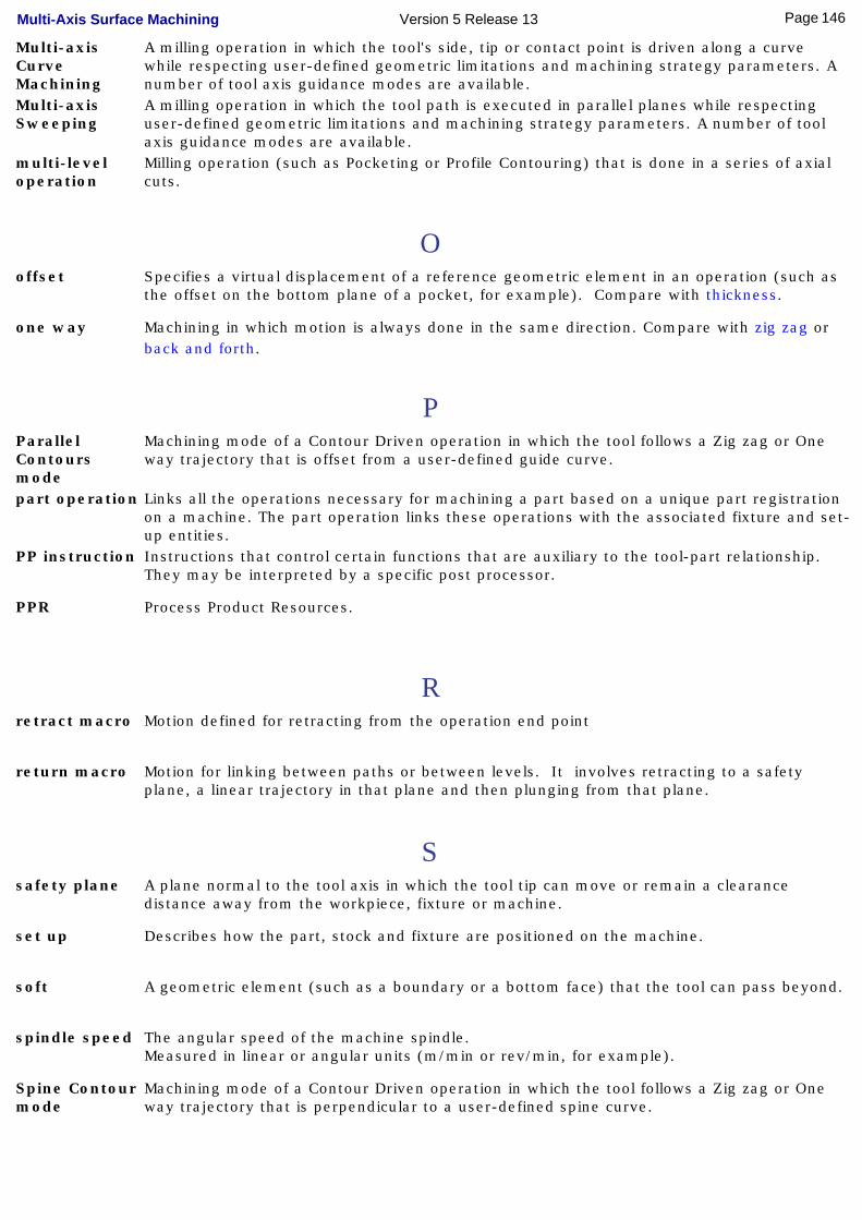
Multi-axis Curve Machining
A milling operation in which the tool's side, tip or contact point is driven along a curve while respecting user-defined geometric limitations and machining strategy parameters. A number of tool axis guidance modes are available.
Multi-axis Sweeping
A milling operation in which the tool path is executed in parallel planes while respecting user-defined geometric limitations and machining strategy parameters. A number of tool axis guidance modes are available.
multi-level operation
Milling operation (such as Pocketing or Profile Contouring) that is done in a series of axial cuts.
Ooffset Specifies a virtual displacement of a reference geometric element in an operation (such as
the offset on the bottom plane of a pocket, for example). Compare with thickness.
one way Machining in which motion is always done in the same direction. Compare with zig zag or back and forth.
PParallel Contours mode
Machining mode of a Contour Driven operation in which the tool follows a Zig zag or One way trajectory that is offset from a user-defined guide curve.
part operation Links all the operations necessary for machining a part based on a unique part registration on a machine. The part operation links these operations with the associated fixture and set-up entities.
PP instruction Instructions that control certain functions that are auxiliary to the tool-part relationship. They may be interpreted by a specific post processor.
PPR Process Product Resources.
Rretract macro Motion defined for retracting from the operation end point
return macro Motion for linking between paths or between levels. It involves retracting to a safety plane, a linear trajectory in that plane and then plunging from that plane.
Ssafety plane A plane normal to the tool axis in which the tool tip can move or remain a clearance
distance away from the workpiece, fixture or machine.
set up Describes how the part, stock and fixture are positioned on the machine.
soft A geometric element (such as a boundary or a bottom face) that the tool can pass beyond.
spindle speed The angular speed of the machine spindle. Measured in linear or angular units (m/min or rev/min, for example).
Spine Contour mode
Machining mode of a Contour Driven operation in which the tool follows a Zig zag or One way trajectory that is perpendicular to a user-defined spine curve.
146Page Multi-Axis Surface Machining Version 5 Release 13
start direction Specifies the direction in which machining will start.
stock Workpiece prior to machining by the operations of a part operation.
Tthickness Specifies a thickness of material to be removed by machining. Compare with offset.
tilt angle User-defined incline of the tool axis in a plane normal to the direction of motion. The tool axis incline is with respect to the part surface normal.Compare with lead angle.
top plane A planar geometric element that represents the top surface of an area to machine. It is always normal to the associated tool's rotational axis.
tool axis Center line of the cutter.
tool change An auxiliary command in the program that corresponds to a change of tool.
tool clash Area where the tool collided with the workpiece during a rapid move.
tool path The path that the center of the tool tip follows during a machining operation.
total depth The total depth including breakthrough distance that is machined in a hole making operation.
Uundercut Area where the tool has left material behind on the workpiece.
VView direction Specifies the direction from which the part is viewed for relimiting and machining.
Zzig zag Machining in which motion is done alternately in one direction then the other. Compare
with one way.
147Page Multi-Axis Surface Machining Version 5 Release 13

Index
Numerics4-Axis Constraint arrow (N) 4-Axis Lead/Lag
Multi-Axis Contour Driven tool axis guidance
Multi-Axis Curve Machining tool axis guidance
Multi-Axis Isoparametric Machining tool axis guidance
Multi-Axis Sweeping tool axis guidance 4-Axis Tilt
Multi-Axis Isoparametric Machining tool axis guidance
AAllowed gouging, check
Allowed gouging, part Allowed lead
Multi-Axis Curve Machining parameter Allowed tilt
Multi-Axis Contour Driven parameter
Multi-Axis Curve Machining parameter
Multi-Axis Isoparametric Machining parameter
Multi-Axis Sweeping parameter Along isoparametric lines
Multi-Axis Curve Machining parameter Along ruling direction
Multi-Axis Curve Machining parameter
APT import
APT source generation
auxiliary command Auxiliary operation
COPY Operator
Copy Transformation
Machine Rotation
148Page Multi-Axis Surface Machining Version 5 Release 13
Machining Axis Change
PP Instruction
Tool Change
TRACUT Operator
axial machining operation Axial strategy mode
Multi-Axis Curve Machining parameter
Bback and forth Between Contours
Multi-Axis Contour Driven guiding strategy Between Curve and Part
Multi-Axis Curve Machining mode Between Two Curves
Multi-Axis Curve Machining mode Bottom finish path style
Multi-Axis Curve Machining parameter Bottom finish thickness
Multi-Axis Curve Machining parameter
CCGR file generation
Clfile code generation
climb milling Closed contour overlap
Multi-Axis Curve Machining parameter
Collision checking on check elements
Collision checking on part elements command
Isoparametric Machining
Multi-Axis Contour Driven
Multi-Axis Curve Machining
Multi-Axis Sweeping
149Page Multi-Axis Surface Machining Version 5 Release 13
Contact
Multi-Axis Curve Machining mode
conventional milling
COPY Operator
Copy Transformation Instruction
DDirection of cut
Multi-Axis Curve Machining parameter
Distance before corner (feed reduction) Distance between paths
Multi-Axis Contour Driven parameter
Multi-Axis Curve Machining parameter
Multi-Axis Isoparametric Machining parameter
Multi-Axis Sweeping parameter
Documentation generation
EEnd extension
Multi-Axis Isoparametric Machining parameter
FFanning distance
Multi-Axis Curve Machining parameter
Fault Feedrate reduction in corners
Multi-Axis Curve Machining parameter Finishing mode
Multi-Axis Curve Machining parameter Fixed
Multi-Axis Contour Driven tool axis guidance
Multi-Axis Curve Machining tool axis guidance
Multi-Axis Isoparametric Machining tool axis guidance
150Page Multi-Axis Surface Machining Version 5 Release 13
Multi-Axis Sweeping tool axis guidance Fixed lead and tilt
Multi-Axis Contour Driven tool axis guidance
Multi-Axis Curve Machining tool axis guidance
Multi-Axis Isoparametric Machining tool axis guidance
Multi-Axis Sweeping tool axis guidance Fixed lead and variable tilt
Multi-Axis Contour Driven tool axis guidance
Multi-Axis Curve Machining tool axis guidance
Multi-Axis Isoparametric Machining tool axis guidance
Multi-Axis Sweeping tool axis guidance
Fixture accuracy Forced contour
Multi-Axis Curve Machining parameter
Ggouge
guiding plane
Hhard geometric element
IInterpolation
Multi-Axis Curve Machining tool axis guidance
Multi-Axis Isoparametric Machining tool axis guidance
Isoparametric Machining command
LLead and Tilt
151Page Multi-Axis Surface Machining Version 5 Release 13
Multi-Axis Contour Driven tool axis guidance
Multi-Axis Curve Machining tool axis guidance
Multi-Axis Isoparametric Machining tool axis guidance
Multi-Axis Sweeping tool axis guidance
Lead angle
Multi-Axis Contour Driven parameter
Multi-Axis Curve Machining parameter
Multi-Axis Isoparametric Machining parameter
Multi-Axis Sweeping parameter
MMachine Rotation
Machining Axis Change
machining axis system
machining feature
machining operation
Machining Process, Apply
Machining Process, Create Machining tolerance
Multi-Axis Contour Driven parameter
Multi-Axis Curve Machining parameter
Multi-Axis Isoparametric Machining parameter
Multi-Axis Sweeping parameter
machining tolerance
Manufacturing Process
Manufacturing Program
Manufacturing View Maximum depth of cut
Multi-Axis Curve Machining parameter Maximum discretization angle
Multi-Axis Contour Driven parameter
Multi-Axis Curve Machining parameter
Multi-Axis Isoparametric Machining parameter
Multi-Axis Sweeping parameter
152Page Multi-Axis Surface Machining Version 5 Release 13
Maximum discretization step
Multi-Axis Contour Driven parameter
Multi-Axis Curve Machining parameter
Multi-Axis Isoparametric Machining parameter
Multi-Axis Sweeping parameter Maximum lead angle
Multi-Axis Contour Driven parameter
Multi-Axis Curve Machining parameter
Multi-Axis Isoparametric Machining parameter
Multi-Axis Sweeping parameter
Maximum radius (feed reduction) Maximum width to machine
Multi-Axis Contour Driven parameter
Minimum angle (feed reduction) Minimum heel distance
Multi-Axis Contour Driven parameter
Multi-Axis Curve Machining parameter
Multi-Axis Isoparametric Machining parameter
Multi-Axis Sweeping parameter
Minimum heel distance, collision check Minimum lead angle
Multi-Axis Contour Driven parameter
Multi-Axis Curve Machining parameter
Multi-Axis Isoparametric Machining parameter
Multi-Axis Sweeping parameter Minimum path length
Multi-Axis Contour Driven parameter
Multi-Axis Sweeping parameter
Multi-Axis Contour Driven
Multi-Axis Contour Driven command Multi-Axis Contour Driven guiding strategy
Between Contours
Parallel Contours
Spine Contour
Multi-Axis Contour Driven operation Multi-Axis Contour Driven parameter
153Page Multi-Axis Surface Machining Version 5 Release 13
Allowed tilt
Distance between paths
Lead angle
Machining tolerance
Maximum discretization angle
Maximum discretization step
Maximum lead angle
Maximum width to machine
Minimum heel distance
Minimum lead angle
Minimum path length
Number of paths
Offset on guide 1
Offset on guide 2
Output type
Position on guide 1
Position on guide 2
Radial strategy mode
Scallop height
Stepover direction
Stepover side
Tilt angle
Tool axis guidance
Tool path style Multi-Axis Contour Driven tool axis guidance
4-Axis Lead/Lag
Fixed
Fixed lead and tilt
Fixed lead and variable tilt
Lead and Tilt
Normal to Line
Optimized Lead
Thru a Point
Variable lead and fixed tilt
154Page Multi-Axis Surface Machining Version 5 Release 13
Multi-Axis Curve Machining
Multi-Axis Curve Machining command Multi-Axis Curve Machining mode
Between Curve and Part
Between Two Curves
Contact
Multi-Axis Curve Machining operation Multi-Axis Curve Machining parameter
Allowed lead
Allowed tilt
Along isoparametric lines
Along ruling direction
Axial strategy mode
Bottom finish path style
Bottom finish thickness
Closed contour overlap
Direction of cut
Distance between paths
Fanning distance
Feedrate reduction in corners
Finishing mode
Forced contour
Lead angle
Machining tolerance
Maximum depth of cut
Maximum discretization angle
Maximum discretization step
Maximum lead angle
Minimum heel distance
Minimum lead angle
Normal to drive curve
Number of levels
Number of paths
Output type
155Page Multi-Axis Surface Machining Version 5 Release 13
Sequencing
Side finish thickness
Side finish thickness on bottom
Spring pass
Tilt angle
Tool axis guidance
Tool path style
Type of contouring Multi-Axis Curve Machining tool axis guidance
4-Axis Lead/Lag
Fixed
Fixed lead and tilt
Fixed lead and variable tilt
Interpolation
Lead and Tilt
Normal to Line
Optimized Lead
Tangent Axis
Thru a Point
Variable lead and fixed tilt
Multi-Axis Isoparametric Machining
Multi-Axis Isoparametric Machining operation Multi-Axis Isoparametric Machining parameter
Allowed tilt
Distance between paths
End extension
Lead angle
Machining tolerance
Maximum discretization angle
Maximum discretization step
Maximum lead angle
Minimum heel distance
Minimum lead angle
Number of paths
156Page Multi-Axis Surface Machining Version 5 Release 13
Output type
Radial strategy mode
Scallop height
Skip path
Start extension
Tilt angle
Tool axis guidance
Tool path style Multi-Axis Isoparametric Machining tool axis guidance
4-Axis Lead/Lag
4-Axis Tilt
Fixed
Fixed lead and tilt
Fixed lead and variable tilt
Interpolation
Lead and Tilt
Normal to Line
Optimized Lead
Thru a Point
Variable lead and fixed tilt
Multi-Axis Sweeping
Multi-Axis Sweeping command
Multi-Axis Sweeping operation Multi-Axis Sweeping parameter
Allowed tilt
Distance between paths
Lead angle
Machining tolerance
Maximum discretization angle
Maximum discretization step
Maximum lead angle
Minimum heel distance
Minimum lead angle
Minimum path length
157Page Multi-Axis Surface Machining Version 5 Release 13

Number of paths
Output type
Radial strategy mode
Scallop height
Stepover side
Tilt angle
Tool axis guidance
Tool path style Multi-Axis Sweeping tool axis guidance
4-Axis Lead/Lag
Fixed
Fixed lead and tilt
Fixed lead and variable tilt
Lead and Tilt
Normal to Line
Optimized Lead
Thru a Point
Variable lead and fixed tilt
NNC code generation Normal to drive curve
Multi-Axis Curve Machining parameter Normal to Line
Multi-Axis Contour Driven tool axis guidance
Multi-Axis Curve Machining tool axis guidance
Multi-Axis Isoparametric Machining tool axis guidance
Multi-Axis Sweeping tool axis guidance Number of levels
Multi-Axis Curve Machining parameter Number of paths
Multi-Axis Contour Driven parameter
Multi-Axis Curve Machining parameter
Multi-Axis Isoparametric Machining parameter
158Page Multi-Axis Surface Machining Version 5 Release 13
Multi-Axis Sweeping parameter
Ooffset
Offset on check Offset on guide 1
Multi-Axis Contour Driven parameter Offset on guide 2
Multi-Axis Contour Driven parameter
one way Optimized Lead
Multi-Axis Contour Driven tool axis guidance
Multi-Axis Curve Machining tool axis guidance
Multi-Axis Isoparametric Machining tool axis guidance
Multi-Axis Sweeping tool axis guidance Output type
Multi-Axis Contour Driven parameter
Multi-Axis Curve Machining parameter
Multi-Axis Isoparametric Machining parameter
Multi-Axis Sweeping parameter
Overall Machining Direction arrow (M)
PParallel Contours
Multi-Axis Contour Driven guiding strategy
Part Operation Position on guide 1
Multi-Axis Contour Driven parameter Position on guide 2
Multi-Axis Contour Driven parameter
PP Instruction
PPR
Process List
Product List
159Page Multi-Axis Surface Machining Version 5 Release 13
RRadial strategy mode
Multi-Axis Contour Driven parameter
Multi-Axis Isoparametric Machining parameter
Multi-Axis Sweeping parameter
Reduction rate (feed reduction)
Resources List
SScallop height
Multi-Axis Contour Driven parameter
Multi-Axis Isoparametric Machining parameter
Multi-Axis Sweeping parameter Sequencing
Multi-Axis Curve Machining parameter Side finish thickness
Multi-Axis Curve Machining parameter Side finish thickness on bottom
Multi-Axis Curve Machining parameter
Simulate material removal Skip path
Multi-Axis Isoparametric Machining parameter
soft geometric element Spine Contour
Multi-Axis Contour Driven guiding strategy Spring pass
Multi-Axis Curve Machining parameter
start direction
Start Direction arrow (S) Start extension
Multi-Axis Isoparametric Machining parameter Stepover direction
Multi-Axis Contour Driven parameter Stepover side
160Page Multi-Axis Surface Machining Version 5 Release 13
Multi-Axis Contour Driven parameter
Multi-Axis Sweeping parameter
TTangent Axis
Multi-Axis Curve Machining tool axis guidance
thickness Thru a Point
Multi-Axis Contour Driven tool axis guidance
Multi-Axis Curve Machining tool axis guidance
Multi-Axis Isoparametric Machining tool axis guidance
Multi-Axis Sweeping tool axis guidance
Tilt angle
Multi-Axis Contour Driven parameter
Multi-Axis Curve Machining parameter
Multi-Axis Isoparametric Machining parameter
Multi-Axis Sweeping parameter
Tool Axis arrow (A) Tool axis guidance
Multi-Axis Contour Driven parameter
Multi-Axis Curve Machining parameter
Multi-Axis Isoparametric Machining parameter
Multi-Axis Sweeping parameter
Tool Change
tool clash
Tool path replay Tool path style
Multi-Axis Contour Driven parameter
Multi-Axis Curve Machining parameter
Multi-Axis Isoparametric Machining parameter
Multi-Axis Sweeping parameter
TRACUT Operator Type of contouring
Multi-Axis Curve Machining parameter
161Page Multi-Axis Surface Machining Version 5 Release 13
Uundercut
VVariable lead and fixed tilt
Multi-Axis Contour Driven tool axis guidance
Multi-Axis Curve Machining tool axis guidance
Multi-Axis Isoparametric Machining tool axis guidance
Multi-Axis Sweeping tool axis guidance
view direction
View Direction arrow (V)
Zzig zag
162Page Multi-Axis Surface Machining Version 5 Release 13