High Speed Machining (HSM) 5-Axis Machining 4/8/2015 HSM & … links/Machining Technology...
25
1 High Speed Machining (HSM) & 5-Axis Machining HSM & 5Axis 4/8/2015 1 CONTENTS Introduction of HSM Advantages Disadvantages Cutting Parameters HSM Techniques Machine Semi-Finishing Toolpaths HSM versus HPM Introduction of 5-Axis Machining Types of 5-Axis Machines HSM & 5Axis 4/8/2015 2
Transcript of High Speed Machining (HSM) 5-Axis Machining 4/8/2015 HSM & … links/Machining Technology...
1
High Speed Machining (HSM)&
5-Axis Machining
HSM & 5Axis4/8/2015 1
CONTENTS
�Introduction of HSM
�Advantages
�Disadvantages
�Cutting Parameters
�HSM Techniques
�Machine
�Semi-Finishing Toolpaths
�HSM versus HPM
�Introduction of 5-Axis Machining
�Types of 5-Axis Machines
HSM & 5Axis4/8/2015 2
2
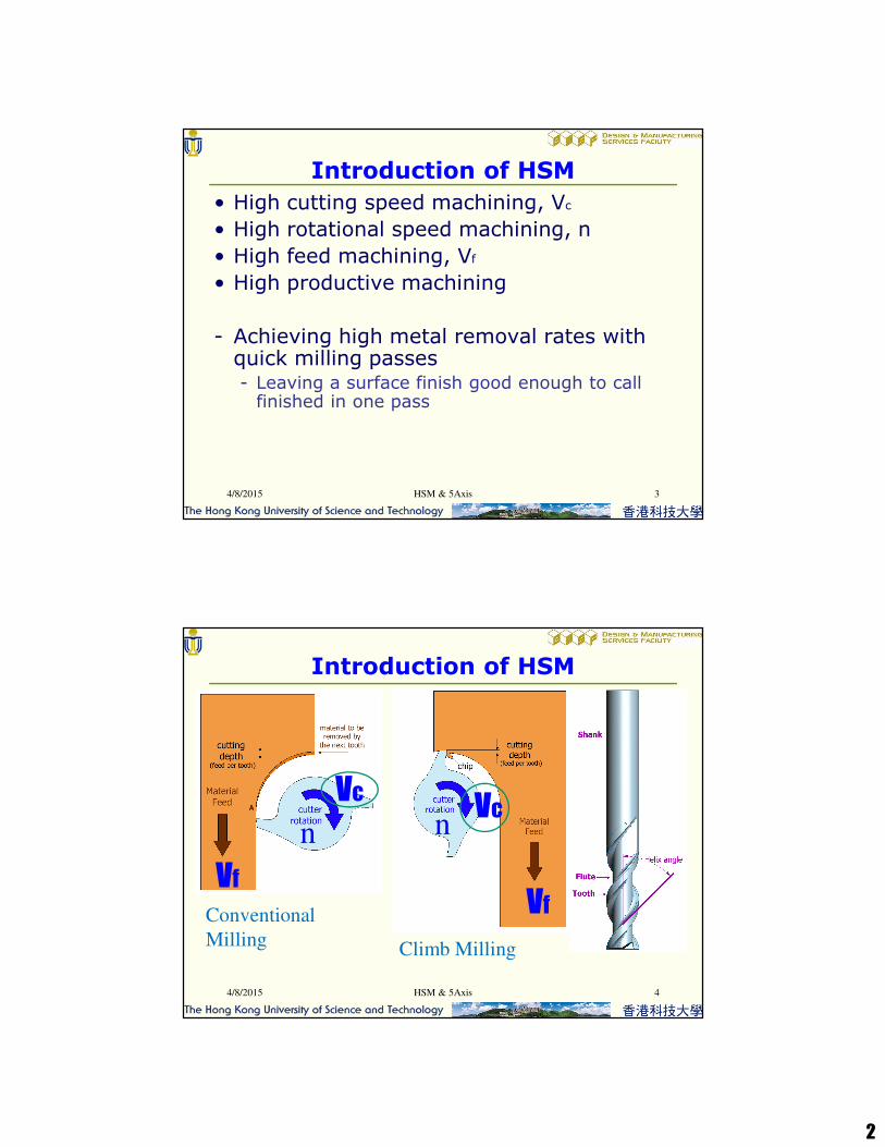
• High cutting speed machining, Vc
• High rotational speed machining, n
• High feed machining, Vf
• High productive machining
- Achieving high metal removal rates with quick milling passes- Leaving a surface finish good enough to call
finished in one pass
HSM & 5Axis4/8/2015 3
Introduction of HSM
Introduction of HSM
n
Vf
Vc
Vf
nVc
Conventional
MillingClimb Milling
4/8/2015 HSM & 5Axis 4
3
HSM & 5Axis4/8/2015 5
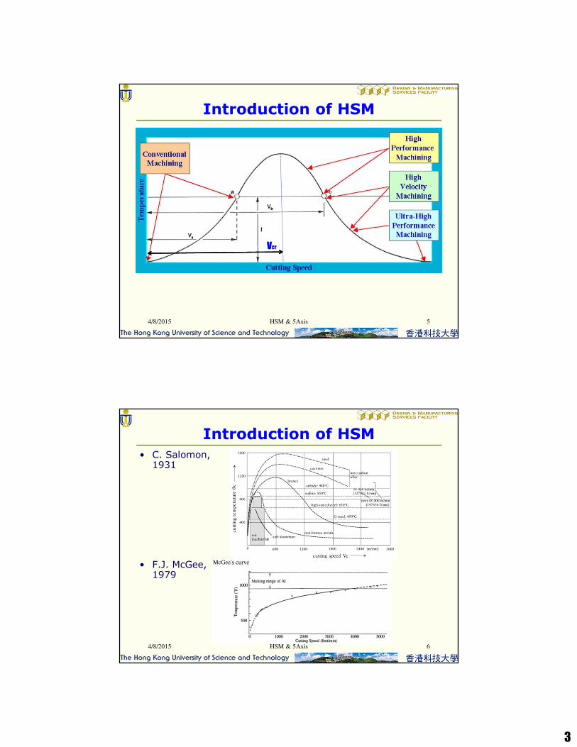
Introduction of HSM
Vcr
HSM & 5Axis4/8/2015 6
• C. Salomon, 1931
• F.J. McGee, 1979
Introduction of HSM

4
HSM & 5Axis4/8/2015 7
Introduction of HSM
HSM & 5Axis4/8/2015 8
Introduction of HSM
5
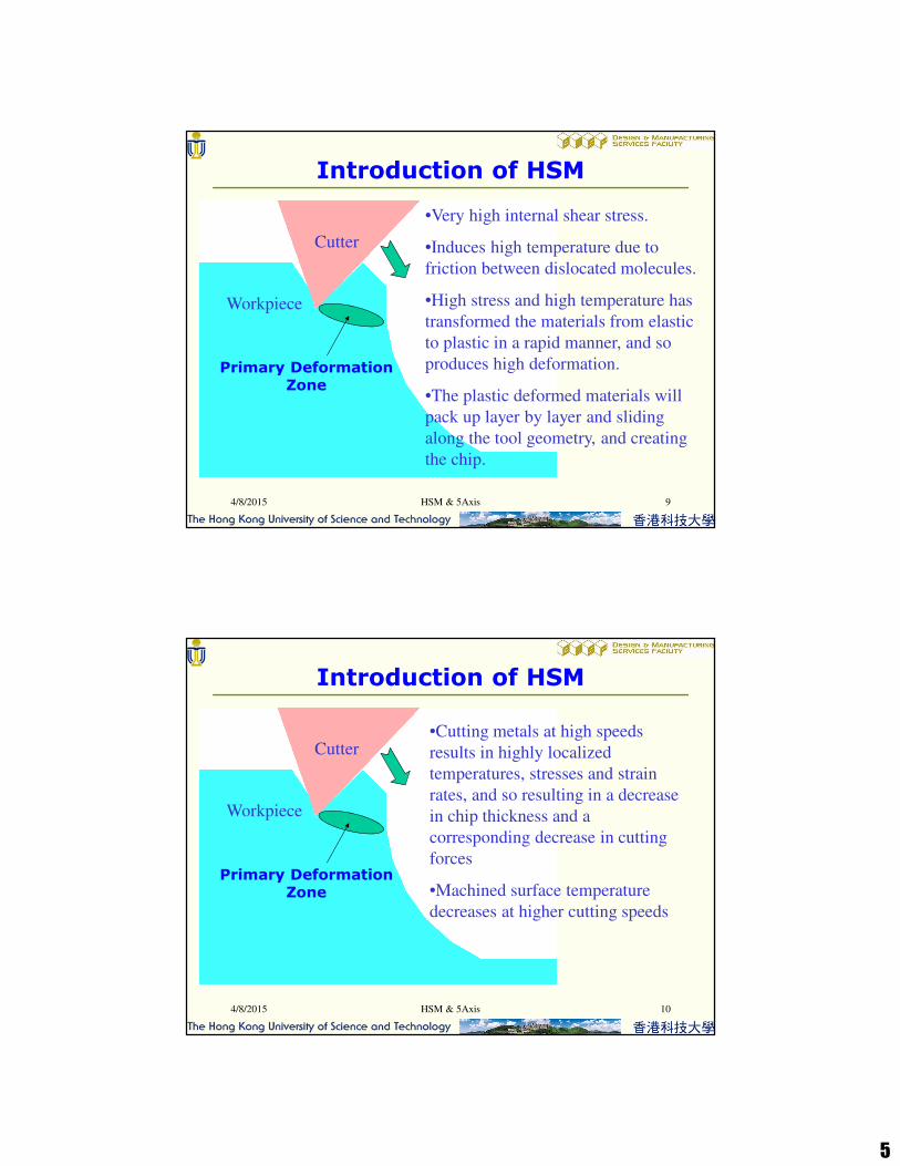
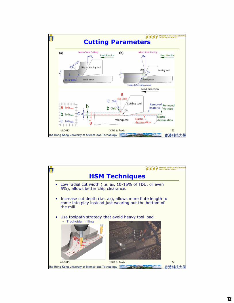
•Very high internal shear stress.
•Induces high temperature due to
friction between dislocated molecules.
•High stress and high temperature has
transformed the materials from elastic
to plastic in a rapid manner, and so
produces high deformation.
•The plastic deformed materials will
pack up layer by layer and sliding
along the tool geometry, and creating
the chip.
Cutter
Workpiece
Primary Deformation Zone
4/8/2015 HSM & 5Axis 9
Introduction of HSM
•Cutting metals at high speeds
results in highly localized
temperatures, stresses and strain
rates, and so resulting in a decrease
in chip thickness and a
corresponding decrease in cutting
forces
•Machined surface temperature
decreases at higher cutting speeds
4/8/2015 HSM & 5Axis 10
Introduction of HSM
Cutter
Workpiece
Primary Deformation Zone

6
•Work done in deforming the chip
and in overcoming the sliding
friction at the tool-chip interface.
•Temperature can be raised to
1200°C.
4/8/2015 HSM & 5Axis 11
Secondary Deformation Zone
Introduction of HSM
Cutter
Workpiece
•Work done to overcome friction which
occurs at the rubbing contact between the
tool flank face and the newly machined
surface of workpiece.
•Escaped materials has spring-back at the
clearance angle of the tool flank face.
•Wearing at flank face is occurred due to
rubbing.
4/8/2015 HSM & 5Axis 12
Tertiary Deformation Zone
Introduction of HSM
Cutter
Workpiece

7
80-90%
To chip
To cutter
5-10% To work
10-20%
4/8/2015 HSM & 5Axis 13
•Heat absorption at HSM
Introduction of HSM
FEATURES EFFECTS
Reduced heat transfer to
the work piece
Minimal workpiece distortion
Eliminates the need of coolant
Reduction of cutting
forces
Part accuracy
Surface quality
Machining of very thin walls
Increased cutting speed Stability of rotating
cutting tool feed rate
Increased material removal
HSM & 5Axis4/8/2015 14
Advantages
8
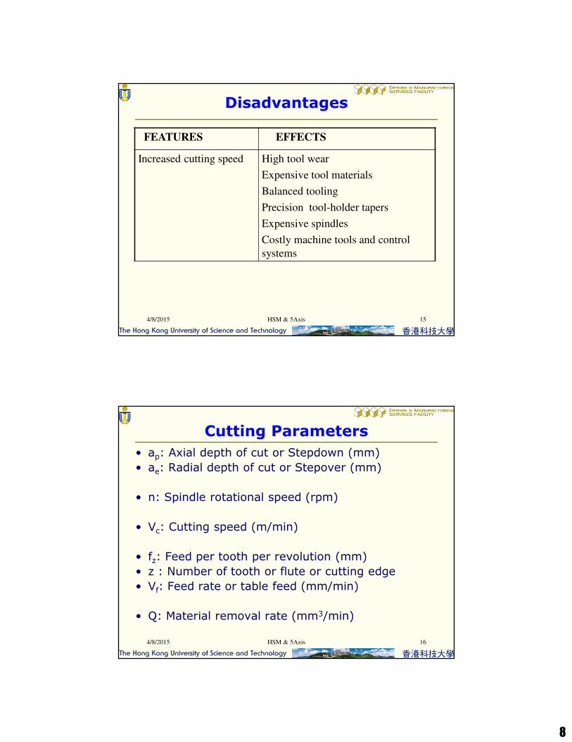
FEATURES EFFECTS
Increased cutting speed High tool wear
Expensive tool materials
Balanced tooling
Precision tool-holder tapers
Expensive spindles
Costly machine tools and control
systems
HSM & 5Axis4/8/2015 15
Disadvantages
4/8/2015 16HSM & 5Axis
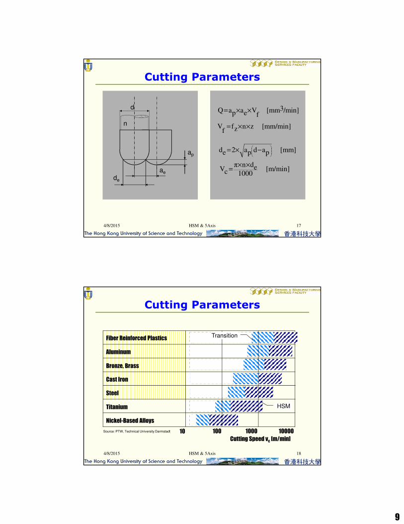
Cutting Parameters
• ap: Axial depth of cut or Stepdown (mm)
• ae: Radial depth of cut or Stepover (mm)
• n: Spindle rotational speed (rpm)
• Vc: Cutting speed (m/min)
• fz: Feed per tooth per revolution (mm)
• z : Number of tooth or flute or cutting edge
• Vf: Feed rate or table feed (mm/min)
• Q: Material removal rate (mm3/min)
9
Cutting Parameters
/min]3[mm f
VeapaQ ××=
[mm/min] znzff
V ××=
d
n
ap
ae
de
[m/min] 1000
ednπ
cV××
=
[mm] padpa2ed
−×=
4/8/2015 17HSM & 5Axis
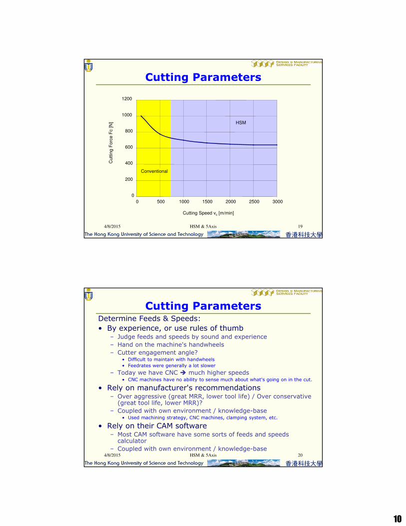
10 100 1000 10000
Cutting Speed vc [m/min]
Bronze, Brass
Cast Iron
Steel
Titanium
Nickel-Based Alloys
Aluminum
Fiber Reinforced PlasticsTransition
HSM
Source: PTW, Technical University Darmstadt
4/8/2015 18HSM & 5Axis
Cutting Parameters
10
0
200
400
600
800
1000
1200
0 500 1000 1500 2000 2500 3000
Cutting Speed vc [m/min]
Cuttin
g F
orc
e F
c [
N] HSM
Conventional
4/8/2015 19HSM & 5Axis
Cutting Parameters
4/8/2015 HSM & 5Axis 20
Determine Feeds & Speeds:
• By experience, or use rules of thumb– Judge feeds and speeds by sound and experience
– Hand on the machine's handwheels
– Cutter engagement angle?• Difficult to maintain with handwheels
• Feedrates were generally a lot slower
– Today we have CNC � much higher speeds• CNC machines have no ability to sense much about what's going on in the cut.
• Rely on manufacturer's recommendations– Over aggressive (great MRR, lower tool life) / Over conservative
(great tool life, lower MRR)?
– Coupled with own environment / knowledge-base• Used machining strategy, CNC machines, clamping system, etc.
• Rely on their CAM software– Most CAM software have some sorts of feeds and speeds
calculator
– Coupled with own environment / knowledge-base
Cutting Parameters

11
d
s
ae / 2
HSM & 5Axis4/8/2015 21
Cutting Parameters
• Cusp (scallop) height s and Stepover ae can be related by:
4sd e
d, sfor
[mm] 2
ds
4
22
≅
<<
−=−
a
ead
d/2
d/2 - s
ve = n . π . d ve ≈ n . π . d ve << n . π . d
ap
d d d
n n n
Rth,1
Rth,2
< Rth,1
Rth,3
<< Rth,1
A B C
Impact of the cutting tool geometry on the effective cutting speed
Impact of the cutting tool geometry on the surface finish
4/8/2015 HSM & 5Axis 22
Cutting Parameters
12
HSM & 5Axis4/8/2015 23
Cutting Parameters
4/8/2015 HSM & 5Axis 24
• Low radial cut width (i.e. ae, 10-15% of TDU, or even 5%), allows better chip clearance.
• Increase cut depth (i.e. ap), allows more flute length to come into play instead just wearing out the bottom of the mill.
• Use toolpath strategy that avoid heavy tool load– Trochoidal milling
HSM Techniques
13
4/8/2015 HSM & 5Axis 25
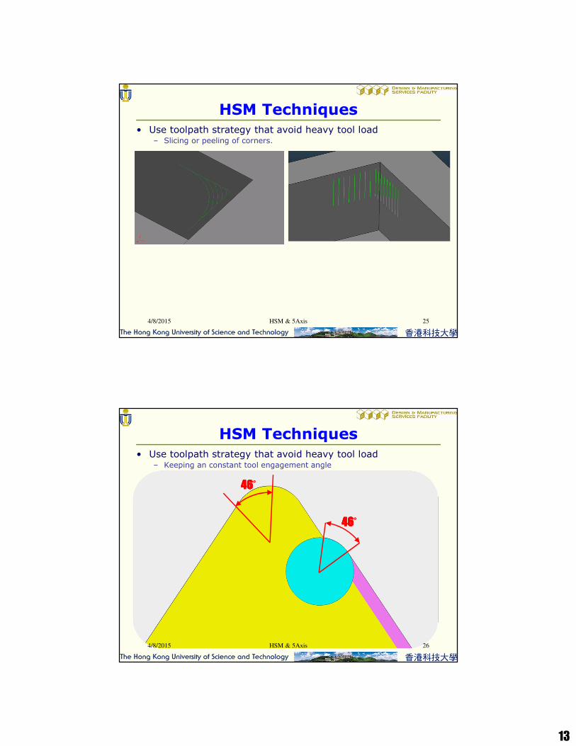
• Use toolpath strategy that avoid heavy tool load– Slicing or peeling of corners.
HSM Techniques
4/8/2015 HSM & 5Axis 26
• Use toolpath strategy that avoid heavy tool load– Keeping an constant tool engagement angle
HSM Techniques
46464646°°°°
46464646°°°°
14
4/8/2015 HSM & 5Axis 27
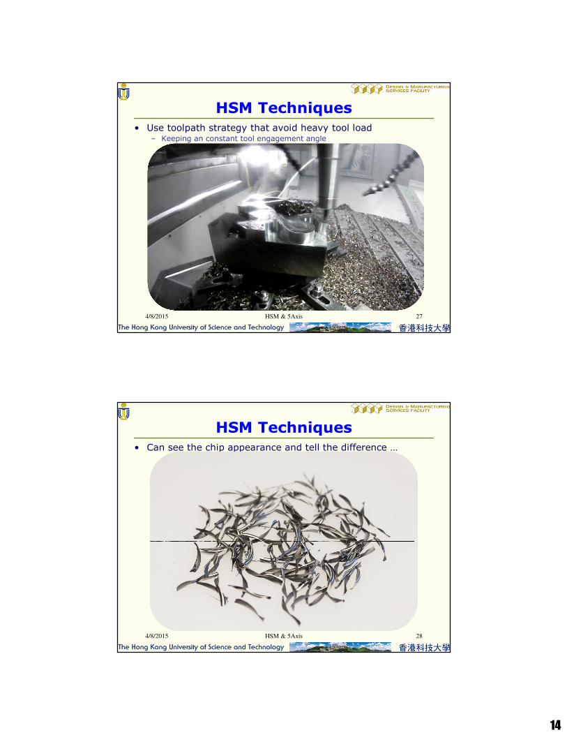
• Use toolpath strategy that avoid heavy tool load– Keeping an constant tool engagement angle
HSM Techniques
4/8/2015 HSM & 5Axis 28
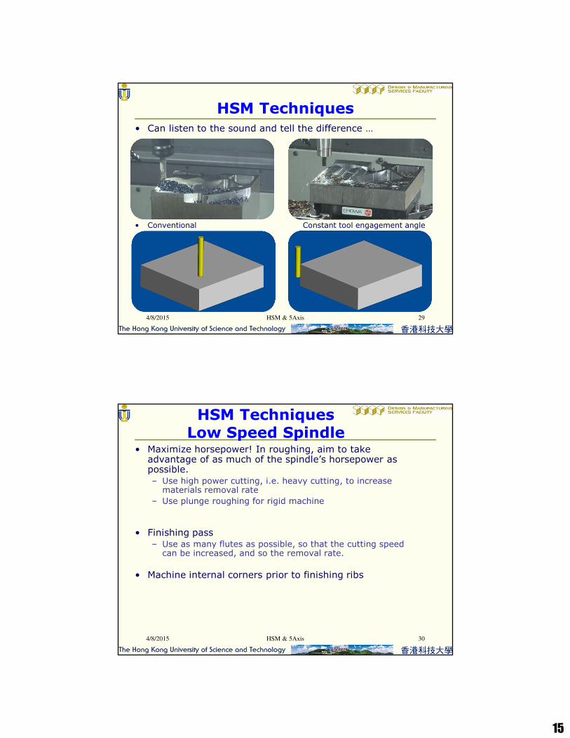
• Can see the chip appearance and tell the difference …
HSM Techniques
15
4/8/2015 HSM & 5Axis 29
• Can listen to the sound and tell the difference …
• Conventional Constant tool engagement angle
HSM Techniques
4/8/2015 HSM & 5Axis 30
• Maximize horsepower! In roughing, aim to take advantage of as much of the spindle’s horsepower as possible.– Use high power cutting, i.e. heavy cutting, to increase
materials removal rate
– Use plunge roughing for rigid machine
• Finishing pass– Use as many flutes as possible, so that the cutting speed
can be increased, and so the removal rate.
• Machine internal corners prior to finishing ribs
HSM TechniquesLow Speed Spindle
16
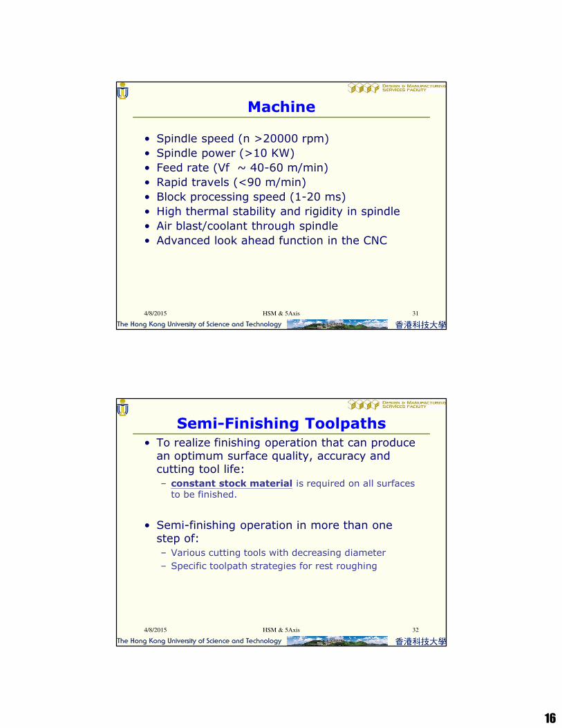
Machine
• Spindle speed (n >20000 rpm)
• Spindle power (>10 KW)
• Feed rate (Vf ~ 40-60 m/min)
• Rapid travels (<90 m/min)
• Block processing speed (1-20 ms)
• High thermal stability and rigidity in spindle
• Air blast/coolant through spindle
• Advanced look ahead function in the CNC
HSM & 5Axis4/8/2015 31
Semi-Finishing Toolpaths
• To realize finishing operation that can produce an optimum surface quality, accuracy and cutting tool life:
– constant stock material is required on all surfaces to be finished.
• Semi-finishing operation in more than one step of:
– Various cutting tools with decreasing diameter
– Specific toolpath strategies for rest roughing
4/8/2015 HSM & 5Axis 32
17
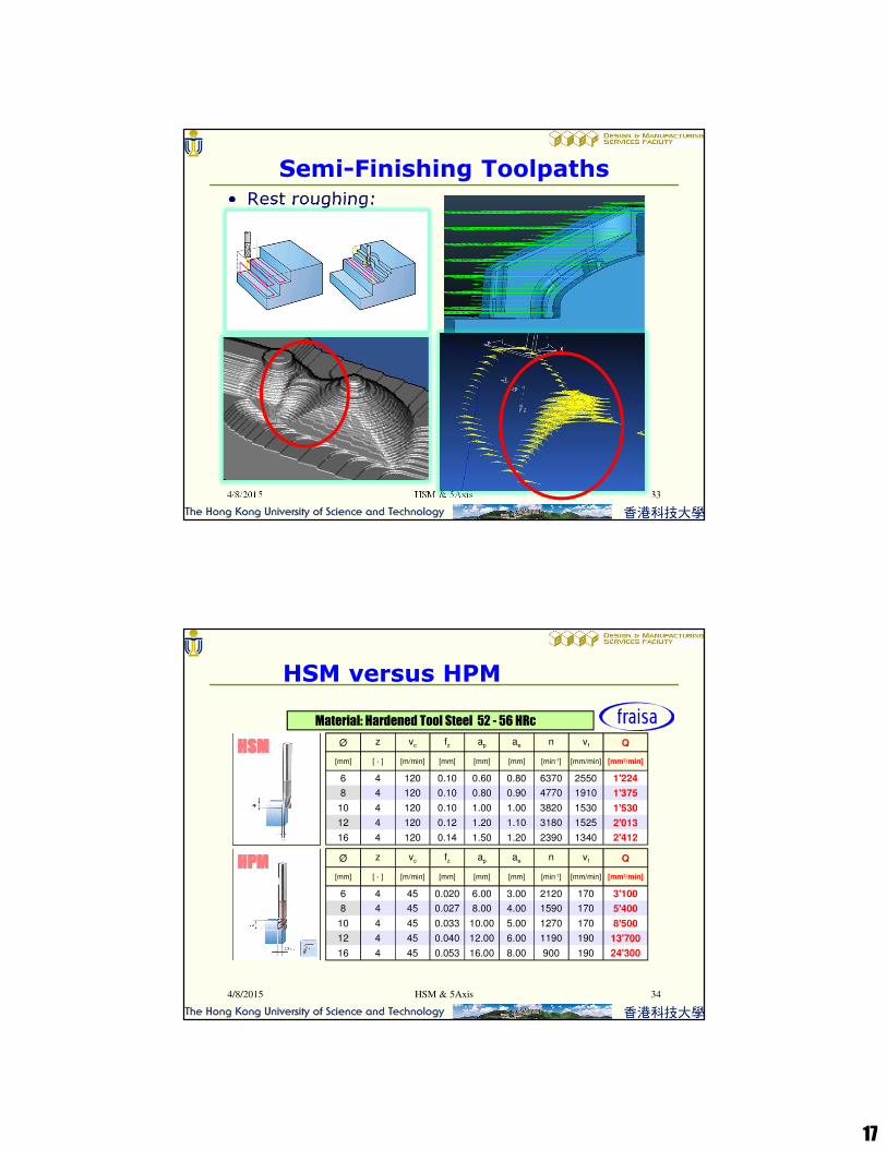
Semi-Finishing Toolpaths
• Rest roughing:
4/8/2015 HSM & 5Axis 33
HSMHSMHSMHSM
HPMHPMHPMHPM
Ø z vc fz ap ae n vf Q
[mm] [ - ] [m/min] [mm] [mm] [mm] [min-1] [mm/min] [mm3/min]
6 4 120 0.10 0.60 0.80 6370 2550 1'224
8 4
10 4
12 4
16 4
120
120
120
120
0.10 0.80 0.90 4770 1910 1'375
0.10 1.00 1.00 3820 1530 1'530
0.12 1.20 1.10 3180 1525 2'013
0.14 1.50 1.20 2390 1340 2'412
Ø z vc fz ap ae n vf Q
[mm] [ - ] [m/min] [mm] [mm] [mm] [min-1] [mm/min] [mm3/min]
6 4 45 0.020 6.00 3.00 2120 170 3'100
8 4
10 4
12 4
16 4
45
45
45
45
0.027 8.00 4.00 1590 170 5'400
0.033 10.00 5.00 1270 170 8'500
0.040 12.00 6.00 1190 190 13'700
0.053 16.00 8.00 900 190 24'300
Material: Hardened Tool Steel 52 - 56 HRc
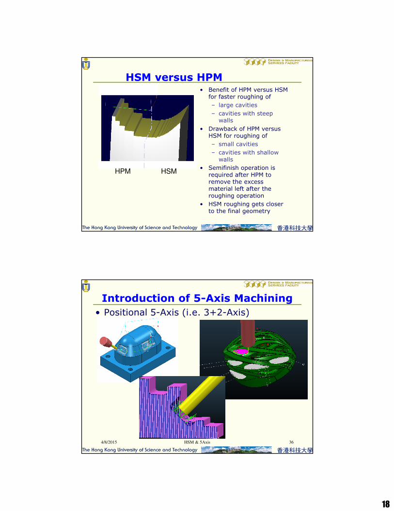
HSM versus HPM
4/8/2015 HSM & 5Axis 34
18
HPM HSM
• Benefit of HPM versus HSM for faster roughing of
– large cavities
– cavities with steep walls
• Drawback of HPM versus HSM for roughing of
– small cavities
– cavities with shallow walls
• Semifinish operation is required after HPM to remove the excess material left after the roughing operation
• HSM roughing gets closer to the final geometry
HSM versus HPM
• Positional 5-Axis (i.e. 3+2-Axis)
HSM & 5Axis4/8/2015 36
Introduction of 5-Axis Machining

19
• Continuous 5-Axis
HSM & 5Axis4/8/2015 37
Introduction of 5-Axis Machining
• Positional 4-Axis (i.e. 3+1-Axis)
• Continuous 4-Axis
• Rotary 4-Axis
HSM & 5Axis4/8/2015 38
Introduction of 5-Axis Machining

20
HSM & 5Axis4/8/2015 39
Types of 5-Axis Machines
Table/Table Table/Head Head/Head
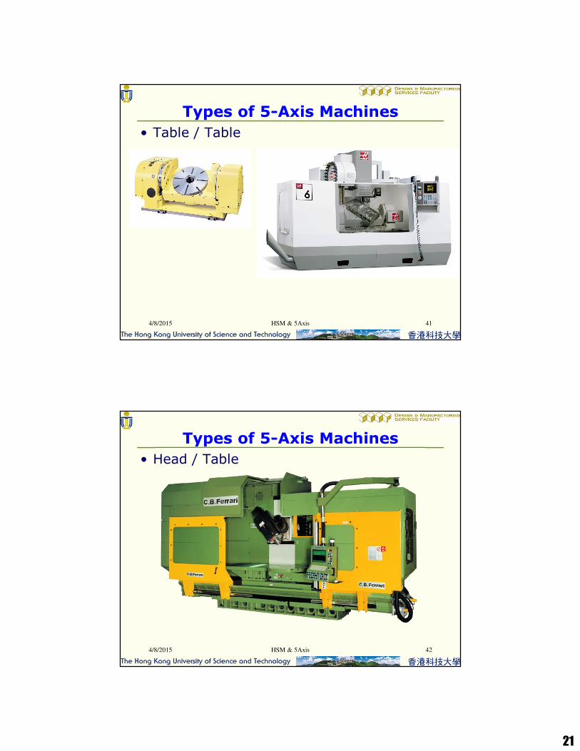
Types of 5-Axis Machines
• Table / Table
4/8/2015 HSM & 5Axis 40
21
Types of 5-Axis Machines
• Table / Table
4/8/2015 HSM & 5Axis 41
Types of 5-Axis Machines
• Head / Table
4/8/2015 HSM & 5Axis 42
22
Types of 5-Axis Machines
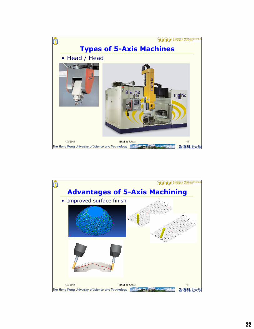
• Head / Head
4/8/2015 HSM & 5Axis 43
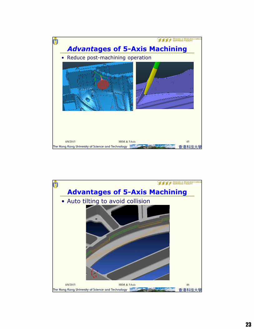
• Improved surface finish
HSM & 5Axis4/8/2015 44
Advantages of 5-Axis Machining
23
• Reduce post-machining operation
HSM & 5Axis4/8/2015 45
Advantages of 5-Axis Machining
• Auto tilting to avoid collision
HSM & 5Axis4/8/2015 46
Advantages of 5-Axis Machining
24
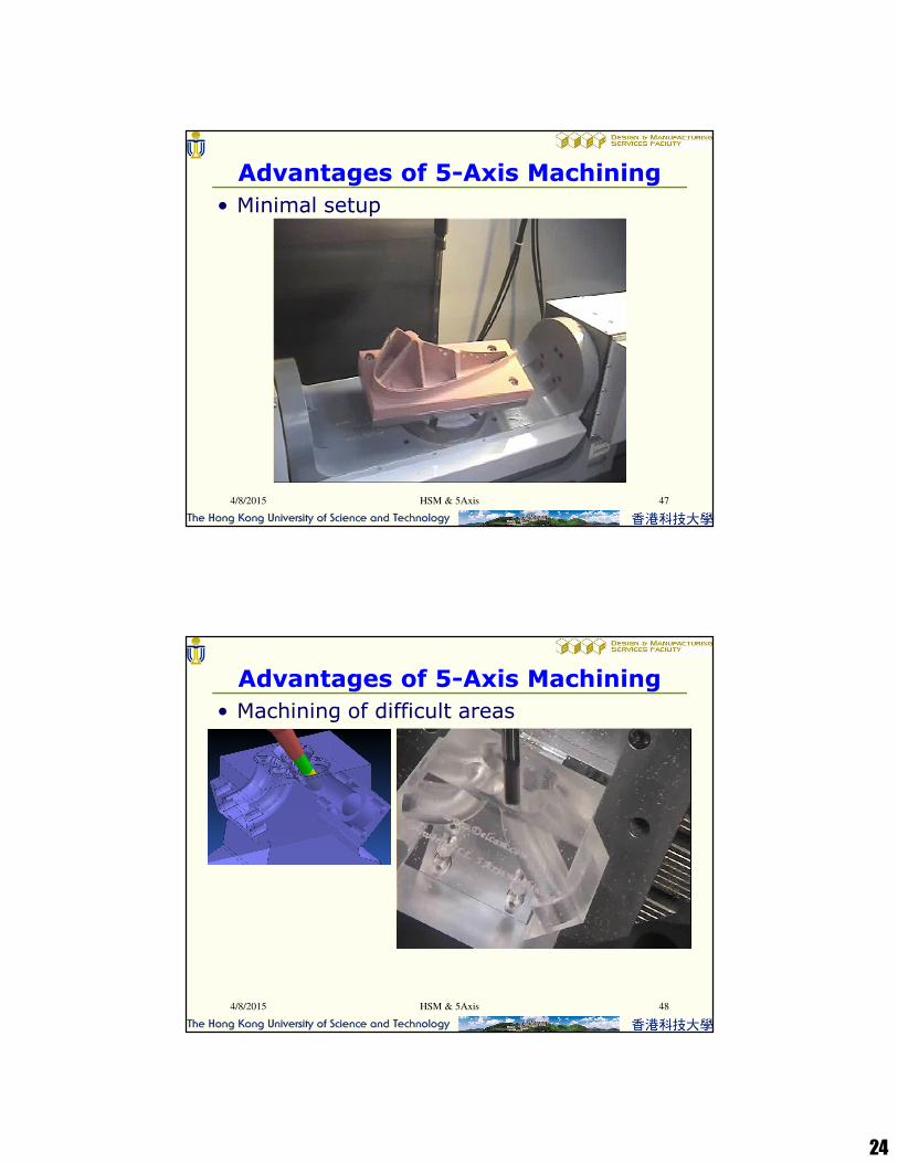
• Minimal setup
HSM & 5Axis4/8/2015 47
Advantages of 5-Axis Machining
• Machining of difficult areas
HSM & 5Axis4/8/2015 48
Advantages of 5-Axis Machining

25
• Polar machining
HSM & 5Axis4/8/2015 49
Advantages of 5-Axis Machining