mJI-mEEE EEEEmohhEEEEEEE EhEEmhEEEEmhEE … · MOS Metal oxide semiconductor MOSFET Metal oxide...
265
L AD-AI07 680 ARINC RESEARCH CORP SANTA ANA CA / 13 TECHNOLOG Y OVERVIEW FOR ADVANCED AIRCRAFT ARMAMENT SYSTEM PROGR-ETC(U)A Al HOSNEG KBAPA.RROS BIS-C27 UNCLASSIFIED 1789-01-1-2406 NL !EE3hhE mJI-mEEE EEEEmohhEEEEEEE EhEEmhEEEEmhEE EEEmhhEEEEmhE.
Transcript of mJI-mEEE EEEEmohhEEEEEEE EhEEmhEEEEmhEE … · MOS Metal oxide semiconductor MOSFET Metal oxide...

L AD-AI07 680 ARINC RESEARCH CORP SANTA ANA CA / 13TECHNOLOG Y OVERVIEW FOR ADVANCED AIRCRAFT ARMAMENT SYSTEM PROGR-ETC(U)A Al HOSNEG KBAPA.RROS BIS-C27
UNCLASSIFIED 1789-01-1-2406 NL!EE3hhEmJI-mEEE
EEEEmohhEEEEEEEEhEEmhEEEEmhEEEEEmhhEEEEmhE.

LEVE L$ Publicatlio 1789-01-1-2406
,70
TECHNOLOGY OVERVIEWFOR ADVANCED AIRCRAFT
ARMAMENT SYSTEM PROGRAMI
I May 1981
Prepared forAAAS TECHNICAL PROGRAM OFFICE
U.S. NAVAL WEAPONS CENTERCHINA LAKE, CALIFORNIA 93555under Contract N60530-80-C-0270 "BUTION ST , A
Akpprovosd foy pyublic release;I Disthbudon Ui,-mIted
-- ' RESEARCH CORPORATION
-~AK

Unclassi fiedSECURITY CLASSIFI(CATION OF THIS PACE Ml. Owe Entered)
REPORT DOCUMENTATION PAGE READ INSTRUCTIONS______________________________________ BEFORECOMPLETINGFORM
1789-01-1-2406
4. TITLE (and Subtitle) 5. TYPE OF REPORT & PERIOD COVERED
Technology overview For Advanced AircraftAiament System Program, _______________
6. PERFORMING ORG. REPORT NUMBER
1789-01-1-2406__.7 AWT QR(s) a. CONTRACT OR GRANT NUMBER(s)
H. Rosenberg K., 4 raman
R.rok G./OanBrya.n N60530-80-C-0270
9. PERFORMING ORGANIZATION NAME AND ADDRESS W0 PROGRAM ELEMENT. PROJECT, TASKAREA & WORK UNIT NUMBERS
ARINC Research Corp.1-2 East Normandy P1.Santa Ana, CA 92702
11. CONTROLLING OFFICE NAME AND ADDRESS
AAAS Technical Program Office myWU.S. Naval Weapons Center13NUBRF-0GEChina Lake, CA 9355527p
14. MONITORING AGENCY NAME & AOORESS(tI different fromt Controllingd Office) 15. SECURITY CLASS. (of this report)
/ Unclass ified/ - ~15 sa. DECLASSIFICATION/'DOWNGRADING
IGOSR BT O STAEMET /SCHEDULE16. DISTIBUION TATEENT(of this Report)
Unlimited
17. DISTRIBUTION STATEMENT (of the abstract entered In Block 20. if difterent from Report)
IS. SUPPLEMENTARY NOTES
19. KEY WORDS (Continue on reverse side if necessary and identify by block number)
AircraftAAAS ProgramStores ManagementLogistics
20. ABSTRACT (Continue on reverse side If necessary end Identify by block number)
_ Presented herein are overviews of state-of-the-art technologies applicable tothe Stores Management System and Suspension and Release Equipment of theAdvanced Aircraft Armament System. Technology briefs are presented forselected areas, and references are made to detailed sources of desiredinformation.
DDI JAN 73 1473 EDITION OF I NOV 65 IS OBSOLETE
/SECURITY CLASSIFICATION OF THIS PAGE (Whlen Dea Enteryf)

TECHNOLOGY OVERVIEW
FOR ADVANCED AIRCRAFT ARMAMENT SYSTE4 PROGRAM
May 1981
Prepared for
AAAS Technical Program OfficeU.S. Naval Weapons Center
China Lake, California 93555
under Contract N60530-80-C-0270
Prepared by
H. Rosenberg, P.E.R. BrooksJ. AldermanK. BramanG. O'BryanG. Wright
Edited by
R. Epps , . ..
% . .
RESEARCH CORPORATION
CORPORATE HEADQUARTERS SANTA ANA BRANCH2551 Riva Road 1222 E. Normandy PlaceAnnapolis, M 21401 Santa Ana, CA 92702
Publication 1789-01-1-2406
Copyright ( 1981
ARINC Research Corporation
Prepared under Contract N60530-80-C-0270,which grants to the U.S. Government a licenseto use any material in this publication forGovernment purposes.

ABSTRACT
Presented herein are overviews of state-of-the-art technologiesapplicable to the Stores Management System and Suspension and Release Equip-ment of the Advanced Aircraft Armament System. Technology briefs are pre-sented for selected areas, and references are made to detailed sources ofdesired information.
NOTICE
The information contained in the technology briefs of thisdocument was obtained from published literature and frompersonal contact with cognizant sources. No claim is madeby ARINC Research Corporation of the validity of theinformation obtained, although efforts were made to assurethat specific items of information were supported by morethan one source.
iii

Ii
II
FOREWORD
This report documents the results of a Technology Overview Project forthe Advanced Aircraft Armament System (AAAS). The project was performed forthe AAAS Technical Program Office of the U.S. Naval Weapons Center, ChinaLake, California, under Contract N60530-80-C-0270.
Described in this report are the approach to performing the project andthe resultant technology interpretations. These interpretations are appli-cable to Suspension and Release Equipment and the Stores Management Systemsfor the AAAS Program.
The effort described herein covered the period from October 1980 throughmid-May 1981, and was performed at the Santa Ana Branch of ARINC ResearchCorporation.
Our company wishes to thank Mr. Tom Leese of the AAAS Program Office andhis staff for their earnest support to the Technology Review Project. Inparticular, we extend our appreciation to Messrs. Phil Gill, Don Piazza,Ron Jones, Clay Panloqui, Ray Smith, Joe Mendiola, Curt Sandberg, andJohn Haney.
We further extend our thanks to those persons and organizations whogranted permission to reproduce the data and material supporting the tech-nology briefs.
v

SUMMARY
A technology overview of Suspension and Release Equipment (S&RE) and theStores Management System (SMS) of the Advanced Aircraft Armament System(AAAS) was conducted. A comprehensive investigation was made of the state ofthe art of a variety of technology disciplines that could potentially beimplemented in the Advanced Development Model for the AAAS Program, as wellas for future aircraft armament systems. Results are presented in thisreport, which has been prepared as a guide for those involved in futuredesign and development efforts for S&RE and SMS.
The study involved a thorough search of computerized data sources, tech-nical reports by U.S. and foreign government agencies, trade and technicaljournals, manufacturer literature, and documented results of developmentalprograms for Navy Participating Field Activities. Several thousandabstracts were evaluated for latest information relative to risk, cost, anddevelopment trends of the selected technology disciplines. Selectedabstracts from these sources were coded in accordance with an appropriatework breakdown structure for the AAAS. Detailed documentation was thencollected and analyzed, and reference sheets prepared on those providinguseful information.
From the detailed data, "technology briefs" presenting an overview ofpresent and projected applications in each technological area were prepared.These briefs address the following technologies:
Suspension and Release Stores ManagementEquipment System
Aerodynamics Materials Computers Large Scale
Controls Pneumatics Controls/Displays Integration
Corrosion Pyrotechnics Data Bus Lasers
Fluidics Reliability Electrical Memory
Hydraulics Safety Electromagnetic Packaging
Manufacturing Environment Reliability
Fiber Optics Software
Languages Switching
vii
,I!

Premised on state-of-the-art information for the above technology dis-ciplines, it appears that significant benefits, in terms of reduced life-cycle costs and overall system performance, are possible for the AAAS if theguidelines presented in the technology briefs are carefully considered infuture S&RE and SMS developments.
viii
ABBREVIATIONS
AAAS Advanced Aircraft Armament System
A/D Analog/digital
ADM Advanced Development Model
A212 Advanced Aircraft Interoperable Interface
AFAL Air Force Avionics Laboratory
AIDS Avionics Integrated Display System
ALOFT Airborne Light Optical Fiber Transmission
APD Avalanche photo diode
ATR Air transport rack
BIT Built-in test
BITE Built-in test equipment
CAD/CAM Computer-aided design/computer aided manufacturing
CCD Charge-coupled device
CDRL Contract data requirements list
CERT Combined environmental reliability test
CMOs Complementary metal oxide semiconductor
CMS-2M Compiler Monitor System - 2M (high-order language)
CRT Cathode ray tube
D/A Digital/analog
dB Decibel
DB Diffusion bonding
DIP Dual in-line package
DM05 Double-diffused metal oxide semiconductor
DoD Department of Defense
DTE Data transfer equipment
ix

EAPROK Electrically alterable programmable read-only memory
EDB Engineering data bank
EEPROM Electrically erasable programmable read-only memory
EMC Electromagnetic compatibility
D4I Electromagnetic interference
EMP Electromagnetic pulse
DIUX Electrical multiplex
EOS End of stroke
FEDB Failure Experience Data Bank
FET Field effect transistor
FORTRAN Formula Translation (high-order language)
GaAlAs Gallium aluminum arsenide
GaAs Gallium arsenide
GIDEP Government-Industry Data Exchange Program
HIP Hot isostatic pressing
HMOS High performance metal oxide semiconductor
HOL High-order language
HSD Horizontal situation display
HUD Heads up display
IC Integrated circuit
ICP Integrated control panel
InGaAsP Indium gallium arsenide phosphide
I/O Input/output
I-SDI Improved SEM
JOVIAL Jules Own Version of International Algorithm Language
KOPS Thousands of operations per second
LCD Liquid crystal device
LED Light emitting diode
LMPV Liquid metal plasma valves
LOCOSST AFAL program for developing low-cost aircraft alloys
LSI Large-scale integration
MAP Modular Avionics Packaging (program)
MDB Metrology Data Bank
MDI Multipurpose display indicator
MDRI Multipurpose display repeater indicator
x

I1
MOS Metal oxide semiconductor
MOSFET Metal oxide semiconductor field-effect transistor
MSG-2 Maintenance Steering Group (Second)
MSI Medium-scale integration
MUSE Modular unit suspension equipment
NASC Naval Air Systems Command
NATO North Atlantic Treaty Organization
NMOS N-channel metal oxide semiconductor
NWC Naval Weapons Center
OMSI HOL developed by Oregon Minicomputer Software, Inc.
PABST Primary Adhesively Bonded Structures Technology
PCB Printed circuit board
PCE Process control equipment
PFA Participating Field Activity
PHP Power hybrid package
PROM Programmable read-only memory
RAM Random access memory
RC4 Reliability Centered Maintenance
R&D Research and development
RFI Radio frequency interference
RFP Request for proposal
RIW Reliability Improvement Warranty
RMDB Reliability-Maintainability Data Bank
ROM Read-only memory
SAM Standard avionics module
S&RE Suspension and Release Equipment
SCR Silicon-controlled rectifier
SEM Standard electronic module
SMA Standard military approval
SMS Stores Management System
SOW Statement of Work
SPF Superplastic forming
SSI Standard stores interface
TAB Tape automatic bonding
TCM Technical coordination meeting
xi

TFEL Thin-film electroluminescent
TMOS A power MOS structure
TTL Transistor-transistor logic
UVEPROM Ultraviolet erasable programmable read-only memory
VHSIC Very-high-speed integrated circuit
VLSI Very-large-scale integration
WBS Work breakdown structure
xii

CONTENTS
Page
ABSTRACT .. ........................ ........ iii
FOREWORD. .. ................................ v
SUMMKAIY ... ............................... vii
ABBREVIATIONS ... ............................. ix
SECTION 1: INTRODUCTION. .. ........................ 1-1
1.1 Background .. ........................... 1-11.2 Project Objectives. ... .................... 1-31.3 Project Scope. .......................... 1-41.4 Organization of Report .. .................... 1-4
SECTION 2: TECHNICAL APPROACH. ...................... 2-1
2.1 Summation of Approach. ..................... 2-12.2 Detailed Technical Approach. .................. 2-2
2.2.1 Project Master Plan ................... 2-22.2.2 Development of Search Strategy. ............. 2-22.2.3 Technology Search. .... ............... 2-la2.2.4 Technical Interpretation. ............... 2-10
SECTION 3: RESULTS. ............................ 3-1
3.1 Suspension and Release Equipment .. ............... 3-1
3.1.1 Technologies Investigated .. ............... 3-13.1.2 Technology Matrix .. ................... 3-23.1.3 Technology Briefs .. ................... 3-2
Code 1: Aerodynamics Technology. ............ 3-5Code 3: Controls Technology ..... ......... 3-17Code 4: Corrosion Technology. .. ........... 3-25Code 6: Fluidics Technology .... .......... 3-31Code 7: Pneumatics Technology .... ......... 3-37
xiii

CONTENTS
Page
Code 8: Hydraulics Technology .. ........... . ...- 43Codes 10 and 11: Materials and Manu-
facturing Technologies .... .............. . 3-53Code 13: Pyrotechnics Technology ..... .......... 3-65Codes 14 and 16: Reliability and
Safety Technologies ..... ................ ... 3-71
3.2 Stores Management System ...... ................. ... 3-79
3.2.1 Technologies Investigated .... .............. ... 3-793.2.2 Technology Matrix ......... .................. 3-793.2.3 Technology Briefs ...... .................. ... 3-79
Code 26: Computers ..... ................. ... 3-83Code 28: Control/Display Technology .. ........ .. 3-95Code 29: Data Bus Technology ...... ............ 3-105Code 30: Electrical Technology ..... ........... 3-119Code 31: Electromagnetic EnvironmentTechnology ....... .................... ... 3-127
Code 32: Fiber Optics Technology ..... .......... 3-135Code 33: Computer Programming LanguageTechnology ....... .................... ... 3-147
Code 34: Large-Scale Integration Technology . . . 3-155Code 36: Memory Technology .... ............. ... 3-165Code 37: Packaging Technology ... ........... ... 3-173Code 38: Reliability Technology .. .......... ... 3-181Code 39: Software Technology ...... ............ 3-185Code 40: Switching Technology ... ........... ... 3-193Code 41: Laser Technology .... ............. ... 3-199
APPENDIX A: TECHNOLOGY MATRICES ...... ................... ... A-I
APPENDIX B: KEY WORD/PHRASE LISTING ..... ................. ... B-i
APPENDIX C: DATA SOURCES ....... ...................... ... C-1
xiv

ILLUSTRATIONS AND TABLES
Figure Page
1 Summary Product Work Breakdown Structure
for Advanced Aircraft Armament System ... ............. ... 1-2
2 Technology Review Project Schedule .... .............. . 2-3
3 AAAS Fourth-Level WBS ...... .................... ... 2-5
4 Example of Technology Profile ..... ................. ... 2-9
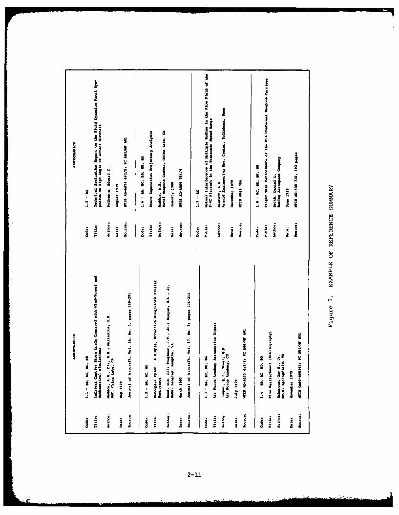
5 Example of Reference Summary ...... ................. ... 2-11
Table Page
1 Coded Technology Matrix, Suspensionand Release Equipment .......... ..................... 3-3
2 Coded Technology Matrix, StoresManagement Equipment ........ ..................... ... 3-80
(Listing does not include figures and tables accompanying technologybriefs. Source data on those figures and tables are presented inAppendix C, Section C.6.)
xv
Section 1
INTRODUCTION
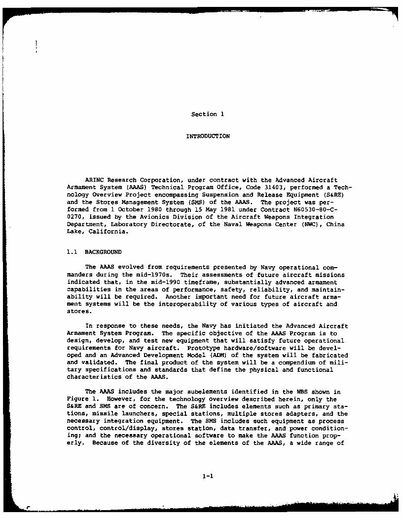
ARINC Research Corporation, under contract with the Advanced AircraftArmament System (AAAS) Technical Program Office, Code 31403, performed a Tech-nology Overview Project encompassing Suspension and Release Equipment (S&RE)and the Stores Management System (SMS) of the AAAS. The project was per-formed from 1 October 1980 through 15 May 1981 under Contract N60530-80-C-0270, issued by the Avionics Division of the Aircraft Weapons IntegrationDepartment, Laboratory Directorate, of the Naval Weapons Center (NWC), ChinaLake, California.
1.1 BACKGROUND
The AAAS evolved from requirements presented by Navy operational com-manders during the mid-1970s. Their assessments of future aircraft missionsindicated that, in the mid-1990 timeframe, substantially advanced armamentcapabilities in the areas of performance, safety, reliability, and maintain-ability will be required. Another important need for future aircraft arma-ment systems will be the interoperability of various types of aircraft andstores.
In response to these needs, the Navy has initiated the Advanced AircraftArmament System Program. The specific objective of the AAAS Program is todesign, develop, and test new equipment that will satisfy future operationalrequirements for Navy aircraft. Prototype hardware/software will be devel-oped and an Advanced Development Model (ADM) of the system will be fabricatedand validated. The final product of the system will be a compendium of mili-tary specifications and standards that define the physical and functionalcharacteristics of the AAAS.
The AAAS includes the major subelements identified in the WBS shown inFigure 1. However, for the technology overview described herein, only theS&RE and SMS are of concern. The S&RE includes elements such as primary sta-tions, missile launchers, special stations, multiple stores adapters, and thenecessary integration equipment. The SMS includes such equipment as processcontrol, control/display, stores station, data transfer, and power condition-ing; and the necessary operational software to make the AAAS function prop-erly. Because of the diversity of the elements of the AAAS, a wide range of
1-1

E4 2:0 041. M E-
0 0 L
Ul
0c 0~ II 'a
4100
1 --- A 0
0... 14 u1 4
0v4 ouo (n c.
a,
014 0 w U4
01 a. o~4 0
w 0 z
044
L,140
~ ~2 ~441
0 4 41-2

technologies will be applicable to the system. It is also anticipated thatmany technologies will have application in more than one AAAS element.
The AAAS is currently in the Requirements Definition Phase and willshortly move into the Design and Development Phase. The Navy plans to awardcontracts for competitive development of AAAS specifications. Based on theGovernment's assessment of those results, a contract will be awarded in thelatter part of FY81 to develop an ADM. Feasibility, cost, risk, and perform-ance assessments will be aspects of the selection of sources for the specifi-cation development and ADM development contracts.
As NWC plans the selection of contractors and manages the AAAS Program,it will be faced with many decisions that will impact the ultimate cost, per-formance, operational dates, and development risks associated with the AAAS.Such decisions will be required during both the source selection for the speci-fication development contracts and the development of those specifications.Many decisions will require sound knowledge of multiple technological areas,both to establish the level of confidence to be assigned to competitive con-tractor inputs and to assess quantitative or qualitative factors beyond thescope of contractor consideration.
It was with the intent of obtaining state-of-the-art technology informa-tion for potential application to the SMS and S&RE that NWC contracted forthe project performed and described in this report.
1.2 PROJECT OBJECTIVES
The overall objective of the Technology Overview Project was to acquireaccurate, up-to-date information regarding aircraft armament technologies.The technolory information provided, along with projections of their develop-ment trends, application risks, and cost directions, will permit NWC techni-cal personnel to evaluate alternatives associated with development of theS&RE and SMS subelements of the AAAS.
In addition to this overall objective, a number of specific objectiveswere defined:
Preparation of a comprehensive master plan to guide and direct theconduct of the project.
Identification, search, and interpretation of appropriatetechnologies and their application to S&RE and SMS.
Compilation of technology information into WBS data packages that
reflect an accurate summation of the latest technologies and esti-mates of their development trends, application risks, and costdirections.
Conduct of technical coordination meetings (TCMs) with authorized NWCtechnical representatives to permit review and approval of projectresults and provide direction between major phases of the project.
1-3

* Documentation of completed phase activities in a series of progressreports, and preparation of a Technology Review Report to present thedetailed results of the project.
1.3 PROJECT SCOPE
The Technology Overview Project included the acquisition, interpreta-tion, and documentation of technology data concerning S&RE and SMS of theAAAS Program. Technology data were obtained from unclassified, confidential,and secret sources of information produced as far back as 1970 and most cur-rently in March 1981.
1.4 ORGANIZATION OF REPORT
This Technology Overview Report is organized as follows:
. Section 1 - Describes the background of, rationale for, and scope ofthis study, and outlines specific project objectives.
. Section 2 - Describes the technical approach to performing the study.
• Section 3 - Presents the results of the study in the form of technol-ogy briefs for S&RE and SMS technologies.
. Appendixes - Provide support information. Appendix A presents tech-nology profiles and matrices, Appendix B contains key word/phraselists, and Appendix C identifies data sources.
1-4

Section 2
TECHNICAL APPROACH
This section addresses the technical approach to the AAAS TechnologyOverview Project. A summation of the approach is presented in Section 2.1,with details provided in Section 2.2.
2.1 SUMMATION OF APPROACH
To accomplish the project objectives listed in Section 1, ARINC Researchformulated a seven-phase technical approach based on the corresponding numberof phases identified in paragraph 4 of the Statement of Work (SOW). Each ofthese phases was divided into specifically defined tasks, as follows:
Phase I - Project Plan
Task I-1: Identify requirements.
Task 1-2: Prepare project plan.
Phase II - Search Strategy
Task II-1: Formulate technology profiles.
Task 11-2: Prepare technology matrices.
Task 11-3: Prepare key word/phrase lists.
Phase III - Technology Search
Task III-1: Perform technology information search.
Task 111-2: Document technology information.
Phase IV - Technical Interpretation
Task IV-l: Assess technology information.
Task IV-2: Prepare WBS data packages.
Task IV-3: Prepare Technology Review Report outline.
Task IV-4: Formulate supplemental effort recommendations.
Phase V - Supplemental Search-Interpretation
Task V-l: Develop additional search words.
Task V-2: Perform supplementary technology search.
Task V-3: Conduct detailed interpretation.
2-1
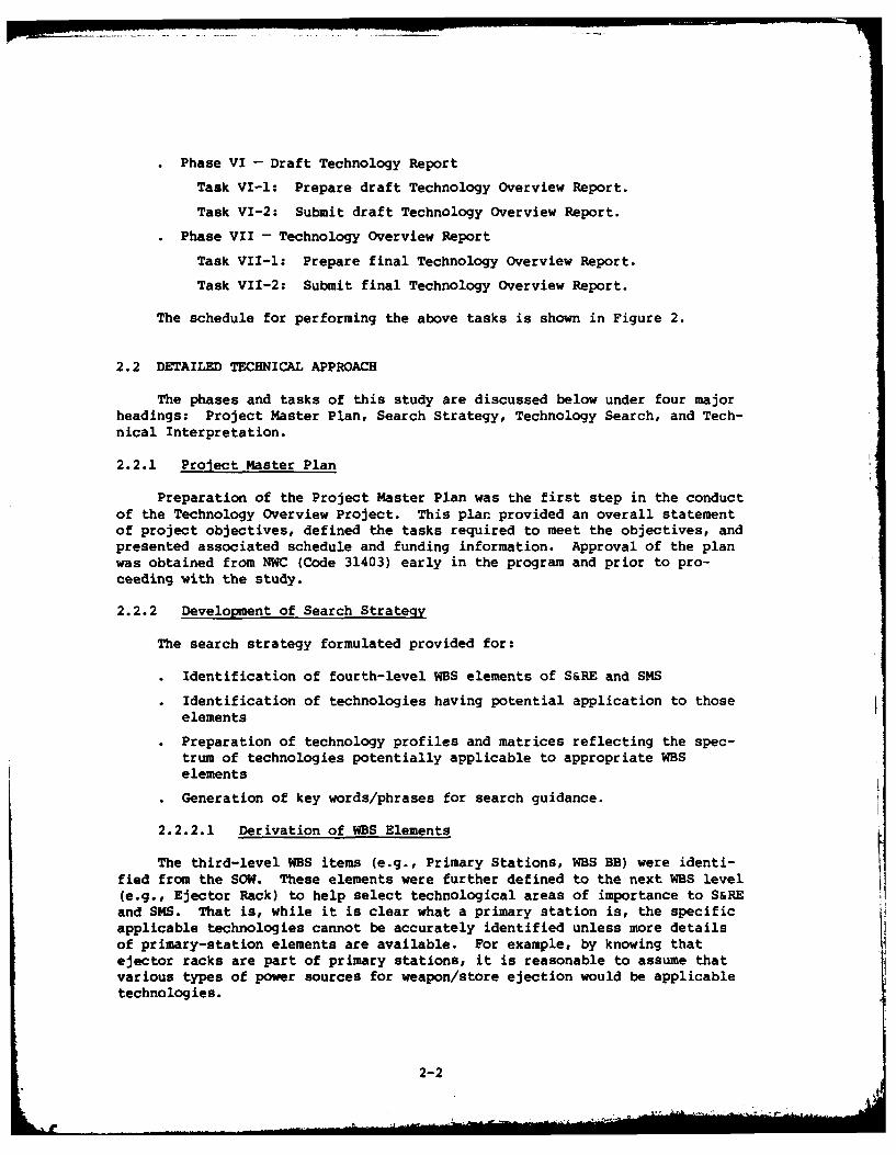
• Phase VI - Draft Technology Report
Task VI-l: Prepare draft Technology Overview Report.
Task VI-2: Submit draft Technology Overview Report.
• Phase VII - Technology Overview Report
Task VII-l: Prepare final Technology Overview Report.
Task VII-2: Submit final Technology Overview Report.
The schedule for performing the above tasks is shown in Figure 2.
2.2 DETAILED TECHNICAL APPROACH
The phases and tasks of this study are discussed below under four majorheadings: Project Master Plan, Search Strategy, Technology Search, and Tech-nical Interpretation.
2.2.1 Project Master Plan
Preparation of the Project Master Plan was the first step in the conductof the Technology Overview Project. This plan provided an overall statementof project objectives, defined the tasks required to meet the objectives, andpresented associated schedule and funding information. Approval of the planwas obtained from NWC (Code 31403) early in the program and prior to pro-ceeding with the study.
2.2.2 Development of Search Strategy
The search strategy formulated provided for:
" Identification of fourth-level WBS elements of S&RE and SMS
• Identification of technologies having potential application to thoseelements
" Preparation of technology profiles and matrices reflecting the spec-trum of technologies potentially applicable to appropriate WBSelements
• Generation of key words/phrases for search guidance.
2.2.2.1 Derivation of WBS Elements
The third-level WBS items (e.g., Primary Stations, WBS BB) were identi-fied from the SOW. These elements were further defined to the next WBS level(e.g., Ejector Rack) to help select technological areas of importance to S&REand SMS. That is, while it is clear what a primary station is, the specificapplicable technologies cannot be accurately identified unless more detailsof primary-station elements are available. For example, by knowing thatejector racks are part of primary stations, it is reasonable to assume thatvarious types of power sources for weapon/store ejection would be applicabletechnologies.
2-2

Ln
4.1-
00 ~z
04 41
S 4 14 4
0 0 0 Q0)z
o 0 0 0 rQ
4. a ( >4 >4 a.>>9 H4 w4 w r tr 0t 0 4.1 fn 0 0 U)$4 4 W
4) W. 0 0- 1-4 Q) >2 .4 n 0-4 00 - &(a r. 'U U) >j 4-
>9140 >4 C 02 4. 1441 'Ul 4.1 LA 0-f014 01m 0 0 -4 44 Zn 0
4. 4 , 4A H- E4 0 4.) U) 0-aU'U 0 0 0 U ) 0
0. 441 $4 C )w. 044 1-44-4 ON41 ) -
0) rd 0 0C 0 0w 4) 0 4 w4 w. 40 1
a. VA 4464 A4 . 0 OA ad E-4
>4
H >H 0 0 0 0H H H > 4 ul 0
w 07 0 w M w 001
.o .o .o .0 C0 .0 .C0a4 a. 0. 0. a, a. a. E-4
2-3

The lower-level WBS elements were identified from AAAS documentation(see listing, Appendix C) for all S&RE and SMS items, and are shown inFigure 3.
For WBS element BH, System Tradeoff Studies, no further breakdown wasmade to lower level elements nor was any effort expended in this study underthat specific category since those lower level elements represent tasks beingperformed by various contractors directly for the AAAS Program. However,much of the information obtained in this study and documented herein is rele-vant to system tradeoff evaluations.
2.2.2.2 Technology Disciplines
Based upon the WBS element descriptions, it was practical to establishsuitable technology disciplines having likely applicability to the AAAS.This was done by reviewing program documentation and conducting technicaldiscussions with NWC specialists in the S&RE and SMS areas. For example, theknowledge that power sources are used for ejector racks of primary stationsled to the decision that hydraulics and pneumatics would be technologies ofimportance to the power-source function.
After the candidate technologies were selected, their scope relative tothe AAAS Program was defined. These definitions are given in the followingparagraphs for S&RE and SMS.
2.2.2.2.1 S&RE Technology Definitions
For S&RE, definitions were prepared for the following technologydisciplines: aerodynamics, control, corrosion, fluidics, pneumatics,hydraulics, manufacturing, materials, pyrotechnics, reliability, and safety.The definitions, as tailored specifically to S&RE, follow.
Aerodynamics. This technology was defined in relationship to theaerodynamic impact of the S&RE station and related elements.Important areas of this technology include wind tunnel facilities andtests, analytical modeling techniques, and structural design effectson aircraft and weapons operation.
Control. The control technology encompasses the components utilizedfor direct use with the weapon control and launching. These controlsinclude such items as couplers, hydraulic and pneumatic valves forregulating pressure, and other elements such as sensors.
Corrosion. The corrosion technology is of a general nature, relatingto all aspects of saltwater and stress corrosion that could be expe-rienced by S&RE. Important to this technology are means of preclud-ing or lessening corrosion.
Fluidics. Fluidics include power sources for weapon launching thatmight be premised on hydraulic or some other fluid system design.Important issues for fluidics include controls, sensors, and relevantequipment and materials.
Pneumatics. Pneumatics include materials, equipment, and methodshaving potential application in powering weapon launching operations.
2-4

Aircraft
ArmamentSystem AA
Dispensers onnco IneracoNdu e s Cneo
and Release |ManagementEquipnent
BA Ri
System /A
Primary Missile Control DisplayStations - Lunchers EquipmentcEupmn
BB BC Iqui ntEjector Rack Rail Laucher Microprocessor Control Panel
Power Source Ejector Rck Minicomputer Radout DviceSafe/Arm Unit (Prgramoble) ucrocomputerConnector Safe/Arm (Digital Coded) Cable/CoSl ector
Dglon Connector BITSSI Interface Power SourcePylon
Store Stre Satato Paag
Secial S sStation PTrasfer
Stores -Idt
Stations Adapter EquipmentW EquipmentBDI BEI DCEjector Rack Power Source Mux. Terminal Cable/Discrete WireDispenser Connector Interface Module ConnectorSafe/Arm Unit Ejector Rack Fiber optics Amp./DriverPylon Safe/Arm Unit Cable/Connector Data Bus
InterfacePoNer Siurce
Aircraft integration Sru t e Conditioning
Parttio
E oxnt B1---H Equipment B--ont F Equipment CG
Connector/Coupler Power Source Isolator (Shock, Voltage ConverterFastener Pylon Vibration) RectifierPylon Tray Power Supply
Rail Launcher Protection CircuitShroud Regulator
FilterSolid State Switch
Tradeoff Configuration ManagementStudies
CSoftwe CCable Digital Code, BITConnector (Hybrid) Dist./CentralCoupler Stores Station Package
Control/Display PackageOp./Exec. Package
S toresManagement[
Integration iCi
BIT ,
Stores Ident.Weapon Fuzing Cont.Aircraft interfaceNuclear Stores RamificationStores Separation SenseSEM/SAM UtilizationSystem Architecture andPartition
Figure 3. AAAS FOURTH-LEVEL WBS
12_5
2-5A
Valves, actuators, pumps, and other components are consideredimportant to this technology. The ability of materials to withstandthe airborne environment as well as the high pressures of the powersource needed for launching are also considered critical.
" Hydraulics. Hydraulics encompass the materials, equipment, andmethods having potential use in powering weapon launching operations.Components such as valves, actuators, and fluids, and their abilityto operate under high pressures, are important aspects of thistechnology.
" Manufacturing. The manufacturing technology includes any techniqueor process that could be used in the development and fabrication ofS&RE. These might include manufacturing methods of forging, brazing,bonding, and superplastic forming and other processes for fabricationof composite structures and alloys.
• Materials. This technology covers those materials that might be usedfor constructing all or part of S&RE. Important materials includecomposites, high-strength alloys, and bonding adhesives.
0
• Pyrotechnics. This technology concerns the devices used to launch orrelease the weapons or stores. Of importance are clean-firing powersources, greater uniformity and reliability, and more power per areafrom propellants.
• Reliability. Technology relating to reliability pertains in thisstudy to S&RE systems. Current practices for assuring and improvingreliability are considered important since new techniques in theareas of pneumatics, hydraulics, and fluidics could be employed inthe S&RE design.
. Safety. Safety was defined in terms of the availability of methodsor systems for improving stores and armament safety. Of particularimportance are aspects of safety involving hazards analysis.
2.2.2.2.2 SMS Technologies
For the SMS, definitions were generated for the following areas of tech-nology: computers, control and display equipment, data bus, electrical,electromagnetic environment, fiber optics, languages, large-scaleintegration, lasers, memory, packaging, reliability, software, and switching.The definitions follow.
Computers. Computer technology encompasses the hardware for poten-tial implementation of the process control equipment (PCE) thathandles executive functions, and provides the "handshake" or arbitra-tion between other SMS modules and between the SMS and the other air-craft avionics. PCE of major interest are minicomputers, microcom-puters, and microprocessors for central or distributed processingapplications. The potential use of microprocessors for system inter-facing and signal processing is also an important part of computertechnology.
2-6
Ls
Controls and Displays. This technology relates to the hardwareneeded for aircrew-to-aircraft interface. Of interest to the SMS aredisplays capable of providing status indications and cues to the air-crew, and the necessary controls and displays to manage the storesload during the mission cycle.
The controls of importance are conventional types such as the slewinghandle, master arm and bomb button, and those used for selectingmodes, deploying stores, and conducting tests and checks.Programmable multifunction controls are considered of interest inperforming SMS functions.
In the area of displays, important features are multifunction CRTswith panels, and discrete indicators for stores operations. Alsoimportant are CRT devices used in support of radar, infrared, andoptical imaging seekers.
Data Bus. This technology is critical to data transfer equipment interms of data buses. Key aspects include bus controllers and remoteterminals, twisted shielded pairs and/or fiber optics data buses,conventional wiring, and safety or security devices. All aspects ofthe MIL-STD-1553B data bus are of significance to this technology.
Electrical. This technology, although very general in scope, wasdefined to encompass hybrid microcircuits and connector componentsfor potential application to the SMS. Hybrid components of particu-lar interest are amplifiers, voltage regulators, power supplies, andA/D and D/A converters.
Electromagnetic Environment. This technology covers electromagneticcompatibility (EMC), electromagnetic pulse (EMP), and electromagneticinterference (EMI) aspects relative to their impact on airborne elec-tronic systems. Design/fabrication techniques, materials, and speci-fications are considered key elements of this technology.
Fiber Optics. The fiber optics technology was defined as thealternative method to the electric-wire approach for transmitting andreceiving signals and data for the SMS. Of importance are devicessuch as connectors, emitters, receivers, cables and others that couldbe implemented for potential use in data transfer equipment of theSMS.
Language. This technology encompasses the higher order languagesapplicable to stores management, and includes all operational andexecutive software required to develop and integrate SMS modules.Important issues for language technology are maturity, documentation,modularity, specification, and system compatibility.
Large-Scale Integration. Large-scale integration (LSI) covers a gen-eralized category of devices or circuits applicable to the SMS. Cir-cuits such as microprocessors, A/D and D/A converters, and others forinterfacing SMS modules with the data bus are important areas of LSItechnology. Tradeoffs and benefits of different LSI structures interms of advantages for SMS application are also important.
Lasers. Laser technology was defined as that portion of the technol-ogy applicable to the use of high-performance emitter capability for
2-7

fiber optics applications. Reliability and availability areimportant issues of laser technology.
Memory. This technology embraces the different memory structureshaving potential application to airborne data storage req-irements,such as that of the process control equipment or microprocessorinterfaces for the SMS. Important aspects of memory devices includeerasability, programability, reprogrammability, nonvolatility, andperformance in terms of storage capacity and access times.
Packaging. This technology encompasses potential methods for enclos-ing, fabricating, structuring, and/or implementing the various SMSmodules. Standard electronic modules (SE4s), standard avionicmodules (SAMs), and other packaging concepts including printedcircuit boards being used in current airborne environments are ofimportance to this technology.
Reliability. This technology comprises state-of-the-art practicesfor enhancing the reliability of airborne electronic systems. Built-in test (BIT) availability, maintainability, failure prevention, andother aspects of reliability are considered important to thistechnology.
Software. The software technology is a generalized area defined toencompass fault tolerance computing, digital code safing, distributedprocessing architecture, and other current software practices thatcould be implemented for the SMS.
Switching. The switching technology includes components and elementsapplicable to the power conditioning function of the SMS. This func-tion includes power conversion switching and interfacing withaircraft power systems; and comprises interlocks, circuit breakers,load switches, relays, protection circuitry, and transient devices.
2.2.2.3 Technology Profiles and Matrices
From the information obtained for the WBS elements of S&RE and SMS, pri-mary-interest technology profiles were prepared. These profiles represent abreakdown of third-level WBS elements into categories equatable to technologydisciplines. Each profile thus represents a matrix of potentially applicabletechnology disciplines versus WBS elements below the third level. Figure 4is an example of a technology profile. The full set of profiles generatedfor this project is presented in Appendix A.
2.2.2.4 Key Word/Phrase Lists (Search Words)
To facilitate the search of information in the computerized data bases,it was necessary to prepare descriptors for use in searching the abstractscontained in the data bases. These descriptors were prepared as key wordsand phrases (search words). These words are in the form of names, titles, orother modifiers describing or defining particular topics of interest withinthe applicable technologies.
The key word/phrase lists were prepared during Task II of Phase II.Supplemental search words were prepared during Phase V, the Supplemental
2-8

9:.' .4p,_ _ _ _ _ _ _ _ _ _ _ _ _ _ _ _ _ _ _ _ _
41 z
0x x x
a
000
20 Q)
mU Z
w (n
2-9

Search Activity, under the guidance of engineering personnel at NWC. The
key word/phrase listings are presented in Appendix B.
2.2.3 Technology Search
The key words and phrases were used to guide the acquisition and compila-tion of information applicable to the selected technology spectra identifiedfor S&RE and SMS. The principal source of information was the computerizedLockheed DIALOG Information Retrieval Service. Other sources included theGovernment-Industry Data Exchange Program (GIDEP), technical magazines andperiodicals, ARINC Research reports, and interviews with DoD ParticipatingField Activities (PFAs) and industry technical personnel. Appendix C providesa more comprehensive explanation of data bases and a listing of PFAs and indus-try personnel contacted.
2.2.3.1 Data Acquisition
Both computerized and manual techniques were used to acquire data. Thedata searches concentrated on obtaining information that would identify thelatest advances in the technological areas of interest. For some of theselected technologies, the search yielded what appeared to be dated informa-tion; however, a review with NWC technical representatives established thatthese technologies had not advanced to the point where the information wasoutdated. For example, only limited information on aerodynamics was identi-fied for recent years (1979-1981). However, NWC personnel expressed the opin-ion that the state of the art of some technologies, such as aerodynamics,progresses at a much slower pace than that of other technologies, such asfiber optics. Hence, the search for best available information on aerodynam-ics was extended back to 1969.
2.2.3.2 Data Selection and Compilation
As information (abstracts, magazine articles, government and industrydata, etc.) was acquired, it was reviewed and screened for applicability tostudy objectives. From the thousands of abstracts acquired, mainly throughthe Lockheed DIALOG system, selected backup documents were obtained for addi-tional detail in the areas pertaining to development trends, cost, and risk.Each selected piece of information was then assigned codes (see Section 3)identifying it with applicable S&RE and SMS WBS elements along with the tech-nology involved. For each piece of selected information, the next step wasthe preparation of reference summaries for all relevant technologies. Thesereference summaries list the technology (e.g., fiber optics), title of article,author(s), date of article, source, and applicable WBS codes. An example ofa reference summary is presented in Figure 5.
2.2.4 Technical Interpretation
This task consisted of the preparation of a technology brief, based onanalyses of the previously mentioned relevant documents, for each technologydesignated as applicable to S&RE and SMS. The briefs are not intended toprovide information to the detail required by designers, but rather to
2-10
A a
m 45. .14A-. .2mb.. S
1 2~4 0 0
S m s
00.5 * 4& 43i
3 ~~u.. U
3i-
n ~ ~ ~Ii 2-11
present an overview of the state of the art in that area. Sources that canprovide more detailed information are identified at the end of each brief.
Information is presented in the technology briefs under the followingheadings:
" Applications. Identifies potential applications of the technology tothe S&RE and SMS WBS elements shown in Figure 3.
• Advantages. Lists major advantages offered by the technology.
" Disadvantages. Enumerates disadvantages associated with thetechnology.
" Risk. Provides a qualitative assessment of the technology risksbased on the information analyzed. Risk is divided into threecategories:
Low - Demonstrated operational success reported for relatedapplications.
Medium - Technology is in developmental phase with promisingsuccess based on preliminary testing and evaluation.
High - Technology is in the early laboratory or early develop-mental phase.
Trends and State of the Art. Summarizes trends in application anddevelopment of the technology.
Cost Direction. Discusses economic advantages/disadvantages and costtrends.
Where appropriate, supplementary charts, graphs, and tables are pre-sented that support the information given in the technology brief. Alsoincluded are the associated reference summaries.
The technology briefs are presented in Section 3.
2-12

Section 3
RESULTS
This section presents the technology briefs resulting from the AAASTechnology Overview Project. Briefs applicable to S&RE are presented inSection 3.1, and to SMS in Section 3.2.
3.1 SUSPENSION AND RELEASE EQUIPMENT
3.1.1 Technologies Investigated
The technologies investigated for S&RE are listed below. The numberpreceding each technology name is a unique code assigned in this study tothat specific technology.
1. Aerodynamics 9. Lasers
2. Bacteria* 10. Manufacturing
3. Controls 11. Materials
4. Corrosion 12. Packaging*
5. Environment* 13. Pyrotechnics
6. Fluidics 14. Reliability
7. Pneumatics 15. Structures*
8. Hydraulics 16. Safety
It is to be noted that certain briefs describe more than one technologyarea, and other briefs overlap technologies. For example, Code 10 (Manufac-turing) and Code 11 (Materials) are combined in one brief since the pertinenttechnical information is common to both disciplines. Further, controls aredescribed in one brief specifically devoted to that topic, and as part offluidics, hydraulics, and pneumatics technologies.
Certain of the above-listed categories, as denoted by asterisks, werenot made the subject of technology briefs. As the study progressed,
3-1
i -1

modifications to the originally assigned categories became indicated. Forexample, laser technology was originally assigned Code 9 under S&RE becauseof its known application as a pyrotechnics initiator. However, this tech-nical category was reassigned to SMS under the fiber optics category when itbecame evident that the latter technology was the area of the most usefulinformation.
Two other technologies considered for S&RE, Bacteria (Code 2) and Environ-ment (Code 5) were amalgamated with Corrosion (Code 4) since the latterreflected the major area of interest to NWC for the AAAS.
Packaging and Structures were incorporated into Materials and Manufactur-ing since insufficient information pertinent to S&RE was identifiable for thefirst two areas.
3.1.2 Technology Matrix
Table 1 is a coded matrix that relates the applicable S&RE technologiesinvestigated, the associated WBS elements (from Figure 3), and number-codedsources of technology information. The coded sources are identified follow-ing each brief.
The matrix is intended to permit quick reference by the user to informa-tion that may impact or influence his specific WBS areas of concern. Forexample, an engineer responsible for the Primary Station (BB) of S&RE maywant to review the latest information on new materials in greater detail thanprovided in the applicable technology brief. Referring to the matrix ofTable 1, he will observe under the heading "Materials" (Technology Code 11) ablock of numbers (1, 3, 5, 8-17, 19-25) corresponding to WBS element BB.These numbers are read as 11.1, 11.3, 11.5, 11.8, etc., and designate thereference summaries provided with the technology brief on Materials.
Certain sources of detailed information may apply to more than one tech-nology or WBS element. For example, referencp 11.1 for Materials is the sameas reference 3.1 for Controls.
3.1.3 Technology Briefs
Technology briefs applicable to S&RE follow. They are presented in theorder listed in Section 3.1.1.
3-2

1.00
100
w 10 'D0 10.10 0
* N-c - 9-- 9...
"9".,
- Io, 0
- - ~~A' 0 -a, co N
<'
- -- q
,2 3. 0 99 ..
en W99 9
u u Ln
- - * *3-3

Code 1
AERODYNAMICS TECHNOLOGY
This technology brief addresses the aspects of aerodynamicsrelating to flutter suppression, conformal weapons carriage, andstores separation.
Potential AAAS Applications
- Wing/stores flutter suppression
- Conformal carriages
- Stores separation (delivery and jettisoning)
Advantages/Disadvantages
" Active Wing/Stores Flutter Control Systems
Advantages
- Possible weight savings
-- Versatility to accommodate a variety of stores
- Reduced drag with attendant fuel saving
- Potentially less costly in terms of redesign
- Offer potential for being integrated with flight control systems,and for being tied to special-purpose computers responding inadaptive manner to counteract structural response
Disadvantages
- Complexity is a reliability concern
- Lack of accurate knowledge of unsteady aerodynamic forces producedby the control surfaces, particularly in the transonic speed rangewhere theoretical predictions are least reliable and flutterconcerns are usually most critical
- Much development effort yet to be accomplished
" Quasi-Active Wing/Stores Flutter Control Systems
Advantages
- Combine desirable features of conventional passive methods with moreadvanced active control methods r
- Relatively simple system
- Associated flutter virtually insensitive to inertia and center-of-gravity location of store
- Simplifies and reduces analysis and testing required to flutter-clear aircraft that must carry a variety of stores
- Potential for reduced drag with attendant fuel savings
- Possible weight savings
3-5
.. .. ... . . . . . .. ,,el ll ... . " .. . . .. .I 1 .. ... ..... . . i -1 ..... ll 1

Disadvantages
- Demonstration of concept limited to analyses and wind tunnel modelstudies
Conformal Weapons Carriage
Advantages- Uniform flow field in proximity of fuselage minimizes weapon
perturbations associated with underwing and clustered multiplecarriage
- Reduced radar cross-section resulting in improved aircraftsurvivability
- Structural rigidity
- Reduced drag with significant attendant fuel savings
- Permits supersonic carriage of stores, compared to subsonic carriageof external stores
- Offers significant potential for improvement of separation anddelivery characteristics for unguided weapons
Disadvantages
- Access to and selective replacement of stores difficult.
- Different size stores require different attachment arrangements
- Stores with different size fins require different positions forattachment.
Stores Separation
Refer to "Trends and State of the Art".
Risk
Risk is generally considered high for early application of most of the con-cepts identified above due to unproven operational applications and addi-tional investigations required to validate their practicality. The conformalcarriage concept appears to be relatively mature, with low-to-medium risk.
Trends and State of the Art
- Flutter Suppression. Considerable research has been made on active andquasi-active aircraft wing/store flutter suppression systems. An example ofprogress on each is discussed below.
Active Systems - A wind tunnel test at the NASA Langley 16-foottransonic tunnel on a scale model of a lightweight fighter was completedin mid-1978 for three stores configurations to demonstrate an activesystem. These configurations were:
A. TLR: AIM-9E; TP (95% span): NI; IP (65% span): AIM-7 (3 in. aft)
B. TLR: Empty; TP: AIM-7 (3 in. aft.); IP: NI
C. TLR: Empty; TP: AIM-9E (6 in. aft.); IP: NI
where TLR - Tip launcher rail; TP = Tip pylon; NI Not installed; IP =Inboard pylon
3-6
Figure 1-1 illustrates Configuration A. Figure 1-2 shows analyticalresults for the three configurations. Figures 1-3 through 1-5 illustratedamping trends with and without the Active Flutter Suppression System(AFSS) in wind tunnel testing.
• Quasi-Active Systems - Quasi-active wing/store flutter systems offer analternative to passive systems or the more advanced active systems. Onesuch concept, called the decoupler pylon, is illustrated schematically inFigure 1-6. The effectiveness of the concept was recently demonstrated byanalyses and wind-tunnel tests at subsonic speeds at the NASA LangleyTransonic Dynamics Tunnel. Basic study conclusions were as follows:
• For all cases studied, the flutter speed of the wing with thedecoupler-pylon-mounted store was higher than the flutter speed ofthe wing without a store.
* The decoupler pylon made flutter relatively insensitive to inertiaand c.g. location.
Predicted flutter trends generally agreed well with results of windtunnel model experiments.
* Wing/store decoupling and attendant flutter speed increase occurredwhen uncoupled store pitch frequency was less than approximately 0.7times the fundamental bending frequency of the wing with the storerigidly attached.
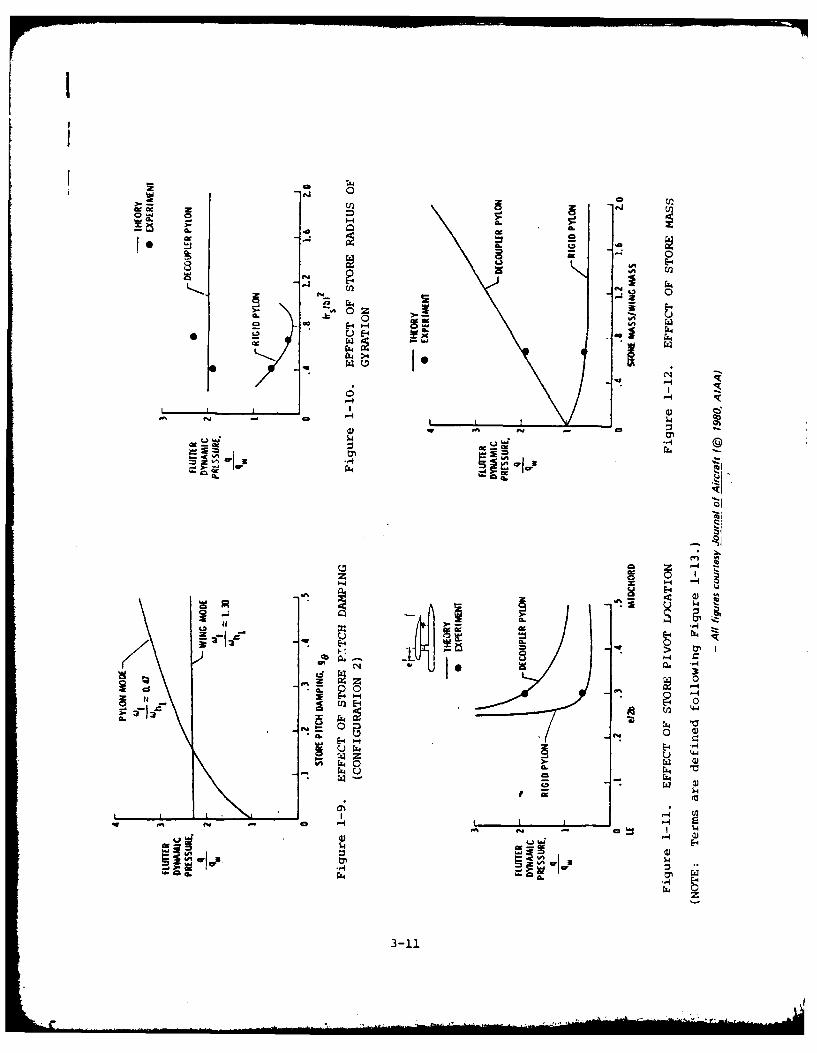
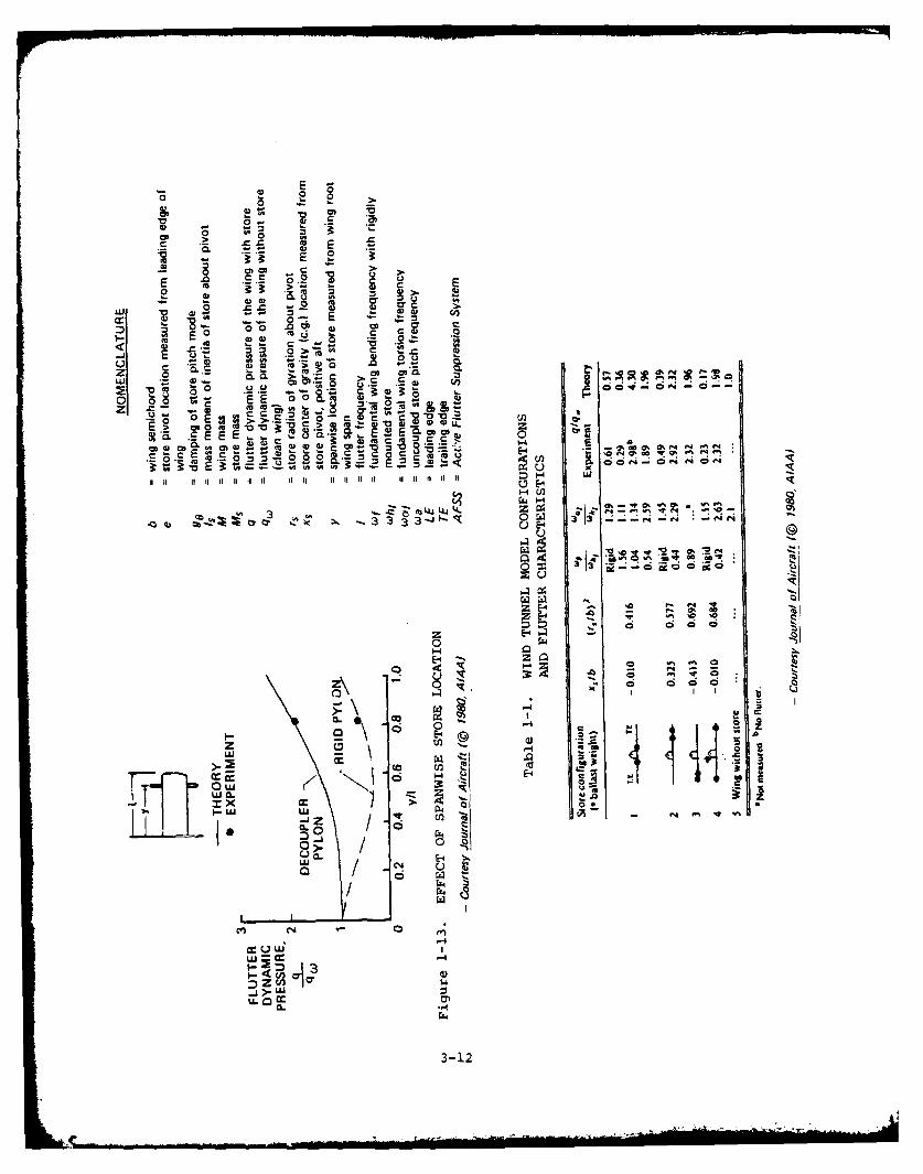
The parameters investigated in the above study are given in Table 1-1.Figures 1-7 through 1-13 show the influence of various parameters affect-ing wing/store flutter.
- Conformal Weapons Carriage. The conformal carriage concept offers attrac-tive potential for improved weapons release (particularly for unguidedweapons), reduced carriage drag, and increased aircraft performance/handlingqualities based on a Navy/Air Force program using the F-4 aircraft. Theprogram included wind-tunnel and flight-test demonstrations in which approxi-mately 200 various weapons were safely released at speeds up to Mach 1.6.With one exception - high-speed pitch problems with aft-row located MK-82bombs - excellent release characteristics in general were reported. TheMK-82 aspect was indicated to be a minor problem that can be corrected byfuture pallet designs and/or proper "tuning" of the bomb ejector racks.
- Store Separation
. Jettison. The aft pivot release system seems to offer the best solu-tion to safely jettisoning aerodynamically unstable items such as pylons,fuel tanks, and MERs. This system is reported to be used for the B-58external fuel tank and all pylons of the F-15. The F-ll pylons and fueltank/pylons employ a limited version of the system.
. Delivery. Delivery of target stores such as unguided bombs anddispenser munitions requires safe aircraft separation and relativelyunperturbed release for delivery accuracy. Promising approaches toimprove delivery include store staggering, dual ejector "tunable" bombracks, self-compensating bomb ejector racks, vertical store separationtechniques, and conformal carriages. Both the store staggering andconformal carriage approaches offer reduction in drag.
3-7

2-5
Cost Direction
No specific data concerning costs was observed in the literature. However,
eventual implementation of the concepts should result in significant life-
cycle cost reductions in terms of aircraft fuel savings due to reduced
inherent drag in some of the concepts, more effective delivery of weapons,etc.
3-8
....................................

o z000
IA. 0 0 0 0
IL. 0
0. 0 0n0
U . a *' 4
0i 0u
0 0 0 -
0 (nU
-40 in
Li .
/0 z z
0I - U
000*
E-3 * z z0 0 0 -
u0'0
3 44
-FX 244 0
0 I u
0
zz
>3-9

zz
C-
II I4
- U) C- -
zi
-00
z z
z MA
A0 i A544 z 4
-
-4 E-z 0-4
2 HE-4,.-iZ Z 0rj
-4
ogCco
.14Z 0) EJc4 -4 -
3-110

E-4 z
00
-E-
01Uit
2 -w
00
-0
u 4)
u UJ
C--4
a3 0 440E11E4 'a)-I
E-4 E- z Iz~ 44>4 uI w 01
*0 0
Q M
-4- I-4 (U
ON3w.± ONIdVVo OIOHNV3.
3-10
II
00
0.
oa I >
C3'
'm ag
-4
0 II
'-4-4
- 0~
0 L
.4.44
z u 0 ,
*44
s.. w wE
0L4
3-11
E
.0 .2?
V 0
E .0 SC 2 '2
ww cc -
-. 0
0 .0
C 0C 4O 0 . ~ 0
z 0 a' 0'
Wi .0 di.. CL CL C C mCL0>0 c0 *.c s
a H 31a2 0 , i 0
0 -EE
Z 9 -aa --
0 . w'- 03..,LJL J4wE .0 v 'aL
m m0c E
1 H0L
Z L4 u30 ?1 4 -
/ f44 V
s 00'-4R
0.0
HL
-12 z

a
...
0
-2 0
- 0
0 0
C 00-0 0
to 0
-40 Z 0,n
ca a o 0 o4.
c Q- 00 00 0c 2 0 0
- C 0
004 a 0a. -0. '
C4 >0 z
.4 a" -Z to A 0 o' 4 'IC -4c,
a c .. a m m* "0 bia 0 * Ua 0 *a~i A a 1; 3 4
z uS 001U z c4
'V
C3 1

*00
r.' 4 . 0 4
.0 a4 C
3c 01-4,l
c44 4011U 1 00
U~- cc4
-c a i a400 4.1 0 4
I- 0 o
0.4 c 41 .0.0x
.0 .41-'l t 00 3l Z
0 002 0 U - a0 0 w
c0~ 0"0 0" 00 "C ,
z~~C UA;- . 01 - ,004,. 0. 0 ~ . 0 V. 0.. 01
i..2 0.: 00
A. 0 414
3 01 0*.. - 4
to (a 0a C
91 0e r5 .- ~ 0 -
0 0 a, 0 43 0.00 &4 -. 04 a , 4 , 4
* a 4,04,0 .~04
I9D 0 V. .34 * ,.44, ~ ~ ~ ~ ~ ~ ~ 1 0 , 0 .I ., 0.LI ., 0 .
0z C-O -' 0
U 4,4
10 04 0
14 0 14

C0
so
- .34
0" C C,
e .: U4 0 0'
0 ah
o Cw 0 10 0
v 4 C
A' -C am
0 - 0
C .-0 0 CC
cc V 0 C-
- UC
l- 0 0 0 0.
OW C
C-
0u
Co..
0 V 3'10

0
oo
m 44
to 4
0. 0 a
0o 40
0.tp a o C
020
I. -- -I f -C(
02 ~~ ~ .4 0 .-
.4* 0 C*~ 0. 4.
442 PC.U 0 0'. C. 40
-- a 0 IV*
91) &q0
v C. .24 02 - -1-
0 0 5. - -16 -
Code 3
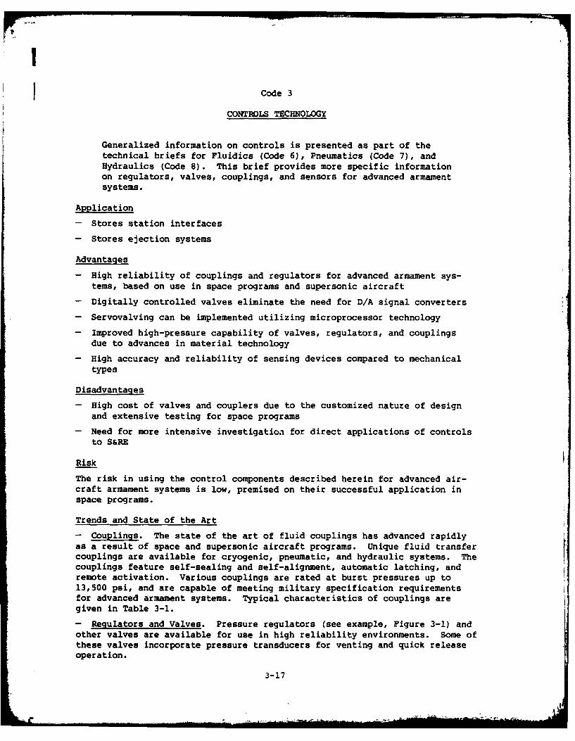
CONTROLS TECHNOLOGY
Generalized information on controls is presented as part of thetechnical briefs for Fluidics (Code 6), Pneumatics (Code 7), andHydraulics (Code 8). This brief provides more specific informationon regulators, valves, couplings, and sensors for advanced armamentsystems.
Application
- Stores station interfaces
- Stores ejection systems
Advantages
- High reliability of couplings and regulators for advanced armament sys-tems, based on use in space programs and supersonic aircraft
- Digitally controlled valves eliminate the need for D/A signal converters
- Servovalving can be implemented utilizing microprocessor technology
- Improved high-pressure capability of valves, regulators, and couplingsdue to advances in material technology
- High accuracy and reliability of sensing devices compared to mechanicaltypes
Disadvantages
- High cost of valves and couplers due to the customized nature of designand extensive testing for space programs
- Need for more intensive investigatioa for direct applications of controlsto S&RE
Risk
The risk in using the control components described herein for advanced air-craft armament systems is low, premised on their successful application inspace programs.
Trends and State of the Art
- Couplings. The state of the art of fluid couplings has advanced rapidlyas a result of space and supersonic aircraft programs. Unique fluid transfercouplings are available for cryogenic, pneumatic, and hydraulic systems. Thecouplings feature self-sealing and self-alignment, automatic latching, andremote activation. Various couplings are rated at burst pressures up to13,500 psi, and are capable of meeting military specification requirementsfor advanced armament systems. Typical characteristics of couplings aregiven in Table 3-1.
- Regulators and Valves. Pressure regulators (see example, Figure 3-1) andother valves are available for use in high reliability environments. Some ofthese valves incorporate pressure transducers for venting and quick releaseoperation.
3-17
New designs are emerging of Mil-qualified hydraulic, pneumatic, fuel, andother fluid systems that employ positive self-sealing techniques to preventhigh-pressure leakage.
New types of high-pressure solenoid valves are evolving. A major driver inthis area has been high-pressure nuclear power systems. Valves are beingfabricated that have interiors unaffected by corrosive fluids, can withstandhigher pressures, and can operate at faster rates.
A new family of digital hydraulic valves is emerging (see Figure 3-2). Asignificant trend in this area is the change from air-gap to wet-armaturesolenoids, providing improved reliability. These valves incorporate ele-ments that control flow in either the forward or reverse direction, and havebeen successfully developed for direct use with microprocessor controlsignals.
Another interesting trend is the emergence of improved cartridge valves forhydraulic systems. These valves are flexible in installation, safe to oper-ate, very serviceable, and of low cost. Cartridge valves (see example,Figure 3-3) are available for such functions as pressure relief, sequencing,regulating, pressure reduction, and checking.
Improved hydraulic system seals are being marketed. In some applications,filled PTFE piston-ring seals are replacing lip seals and metallic pistonrings to provide less leakage and lower friction (see Figure 3-4).
- Sensors and Transducers. Capacitive transducers can handle measurementsfrom 0.01 to 150,000 psi and provide both dynamic and static readings withgood frequency response. A recent development is a transducer that comparesthe voltage across a sensing capacitor element with that of a reference capa-citor. The device integrates the voltage difference to produce an outputlinear to pressure variations.
Some transducers employ integrated circuitry to convert analog signals todigital form without the need for separate A/D conversion.
Wider use of strain gauges is being made in aircraft and missile systems.These gauges employ thin-film techniques to provide stability and high accu-racy. Strain gauges can operate at pressure ranges as high as 10,000 psi.Semiconductor piezoresistive strain gauges are supplanting wire and foiltypes, and can serve as accelerometer sensors.
Transducers housed in stainless steel for application in corrosive environ-ments operate from -65" to +525*F. One of these types uses a silicon or sap-phire diaphragm with epitaxially grown piezoresistive silicon strain gaugeson the surface. The devices are isolated internally from thermal and mechan-ical stress.
A new family of semiconductor sensors has potential use in advanced armamentsystems. These sensors operate on a principle based on the linear negativetemperature coefficient of the base-to-emitter diode voltage of a silicontransistor. Silicon device sensors such as thermistors have highly accuratetemperature coefficients over the -550C to +125 0C range.
Optoelectronic sensors of many types appear suitable for potential S&RE sen-sing applications. These optical sensors are discretely packaged or incor-porated as chips on substrates with processing circuitry.
3-18

Cost
No specific cost directions have been noted for the coupling, valve, andregulating components described in this brief. However, improved reliabilityshould promote reduced life cycle costs of armament systems if these compo-nents are implemented. The cost of semiconductor sensors is expected todecrease significantly within the next few years, to the point where they areless expensive than comparable mechanical devices.
3-19

CL~CL 0 cm ( z
a cI0
-c
0 W-
_ 04
dxZp
>a
0///CL 0 0
£E-4
13 Ea .16I * 0
-4
p4 >6 4 -Il c 0
EK 3: D:
3-20

- . 1 2 !
-3 I
ZZ 0 L
U3 Ia. -,-
a I ,'
o|a I ;*., ; ' .. .. .
a', ."- :
I- 8 ii
! 8 . - 4 -= -
- a ! -, "
z
E-41
:* ,. , + i ++ +! + - "
= a "* a Ij < +".a + . .. :
0*
-I I ,
U.. +I,-. , - I a, ; , -~ l ' ! :
E-4 - _
i E
Hi- A =I I
3-21
2 1
U EN
j I020
Ca -ma m 9 . g
20 c c
0
20 0 - 2aLO 2C 2 UC
0 to Aa 0 14 " a
0 0
01 2" C U0C
0 0 0) 0. & 2 -4, 0
4 2 C 2c 0
0. 0.l OW 41.
0~~ > 1- 2
2 .>.- - 2 - 0 = tE 0*~C U J 0 0 * U ~ - i
0 - ~ - OC Z - 2 0 0 U a 13
00
101.0
u
In C2 21 C
2o c
C 8N
C, 2- - 2 -
2w 02 f S0to
2 .0. ~ U 0 >
2 l 3-22
2 U- 2 2

K00K
40 .0
o Cd
41 0
>4
92 4- go 0 0 Co 0 4-
0 *4; 0 c4 0>4
4 a 0. K
0 4 0w 0 4m00~~ 0.. .
.0 44 -C0
104 0' 0J 0.4 44044 0
OM 0' a W
I 4 a -l- n u C 4 m -C
8 ~~~ - 4 4 i
0-00
a01 0 0 44Z 04 M' K U . 0 .4 4 64
.0 - C 0 ~ ~ 44- 04
In 0.~4 4 C K 4 ~ K 0K 4c 9K a 10444 K 6. - 0 . '
u 4 0 C- - 4 - 0.
0. KZ 0 If -1 0.0 a. 00
44U -1 .0 44 v- 4 0 4 - 4 44 . 44 0
u400
0. :E, -
43-23

o 0
00 w
00to 0
-I 00 a
0' a3-24

Code 4
CORROSION TECHNOLOGY
Primary interest in corrosion technology lies in AAAS structuresand electronic connectors, as discussed in this technology brief.
Potential AAAS Applications
- S&RE structures and mechanical elements
- Electrical connections, such as those of the Stores Stationinterfaces (see Code 30)
Advantages and Disadvantages
Corrosion-prevention techniques and materials for advanced armament programsoffer obvious benefits of reduced cost and increased system availability.Disadvantages of the materials described in this subsection are covered underCodes 10, 11, and 30 for the Manufacturing, Materials, and Electrical Tech-nology disciplines, respectively.
Risk
The risk associated with applying the various corrosion prevention tech-nologies described herein to advanced aircraft armament systems is consideredlow to medium. Each technology area offers significant promise, and if prop-erly evaluated could prove beneficial to selective areas of the AAAS.
Trends and State of the Art
The following corrosion technologies are considered of interest for the AAAS:
- Composites. Composites such as graphite/epoxy and Kevlar/epoxy have demon-strated acceptable levels of cihemical and stress corrosion resistance, andsuitable strength for high-performance military aircraft structures. A "bot-toms up" approach to designing the S&RE mechanical structures might considera composite for the conformal carriage and/or rack.
- Alloys. New lightweight alloys of aluminum, steel, and titanium haveimproved chemical- and stress-corrosion properties over those of conventionalalloys used for aircraft structures. Advances in production methods such asvacuum processing, casting, and molding enhance the availability of aluminumand titanium alloys for large-area structures such as advanced armament sys-tems. Aluminum-copper and aluminum-zinc alloys have demonstrated successfulperformance in supersonic aircraft of NATO countries.
- Coatings. New techniques are emerging for coating metallic and non-metallic materials for prevention of corrosion. These techniques includevacuum and vapor deposition processes for plating alloys of titanium and alumi-num with coatings such as cadmium, chromium, and titanium nitride. Ion plat-ing is an example of the above technology.
Another process, electrodeposition of aluminum, is utilized in the aircraftindustry for protection of wings, steel and titanium fasteners, and compositematerials.
3-25

A new epoxy coating for protecting naval shipboard antennas utilizes fourseparate applications consisting of three primers and a top coating. Totalthickness is 12 to 20 mils.
Numerous paint systems have been developed by the aircraft industry, such aspolyurethane topcoating over an epoxy primer, that provide the durability andcorrosion resistance needed for advanced armament systems.
- Adhesive Bonding. The recent use of adhesive bonding by the Air Force inthe PABST program has resulted in the elimination of sources of stress andchemical corrosion (e.g., rivets and welded joints). Adhesive bonding hasalso been implemented in several programs for NATO aircraft, with a good his-tory of success, and might be suitable for AAAS structures such as conformalcarriages.
- Corrosion-Resistant Connectors. New connector types are highly resistantto corrosion. The devices are moisture sealed in the following manner: whenthe connector is exposed to pressure extremes, its mating surfaces are forcedtogether and the sealing effectiveness is increased. These devices can func-tion at pressures up to 250 psi. This technique, along with the use of con-tact plating materials of higher purity, improved surface-preparation methodsprior to plating, and other improvements including chromate and cadmium plat-ing and aluminum alloys for shells, are major trends in connectormanufacturing.
Cost
Relevant cost information for composites and alloys appears in the technologybriefs for Codes 10 and 11. For all trends discussed herein, decreasedcorrosion for advanced aircraft armament systems should result in attendantreductions in life cycle costs. Both material and maintenance laborrequirements will be reduced.
3-26

0
0 -
0 0
>. >0% 4
0 0
a.0-; 0 0
In cc 0. go
o 0
c w 0 0*c 0
V 0 N M 0 m m0 -Z ; 0 6% -C
1% 0% Uo - % 06 %) o - 0 6
0 ~ ~~~~~ >44 . 0 -66
*00
-c~ E- m cc
UC0% 0%5 ~ % 0 0 6. 0
-c 0 0
* 0 6%) 4.0 ~ . .4 0 ~ . 0 do
0% 0 0 0% 0 0 0%0 20% 0% % .4 06% % 0 - >0m.0% . 244 - 6% 0% 0 0 .- - 0% 0 0 0 6 -
- 0 0
V oV
0- - 0
Iv 0 1" N
00I
0, IN. - X a
to 6% o0
Q0 m ,cw m a 8 U
33 m0 - c
.3 0.4 u 1 -
c 4 0. 0 -
oo 0o w 24. o .U 0% 0% 41 0 0
6%)~~4 .0I 004 -
to w* Ro -o 0. 4 4
.4~~~4 N..0 20 -
O~~ ~ 09 u00N 0 U 0. 0 .
0% ~ CI % 6% 0%0 6 64 0 63-27.
4 6
00
.00
0. 1
Si 0
.00
00 41
c ~ 0
*1'0 0 ,
to. 0 -
10 to 0041 .0.o
04 20.0 8 -O 0eW c 0 000 02 UG M
0 -01 0 Si
2 .0 0
0~~ 0 i 0
4 116 1 2 0 0 4 0 ~ 1 ~ .
Cd w- 0 a
*Si 0 . 0Si* * d 6 000C1
r 1 0 m.00 I *00 u 0
41 ~ ~ ~ ~ ~ ~ > >1C0 1 . ~ 6 - ~ 0 S 6 '
060 "s U0 - v
-o 00 =w 0 .
0Z0
"cc ;: d" 01
3-2

IID
a 0a
- C
U C
4 01c c
4* C
C C II
UD I
a.. WO)D0ID I
od 0 -I
A- ID. IDl a0Ca
U)~~~~~C C - Uou . II0 I. .I. I
H.~ ... ~ .....0 .. I

Code 6
FLUIDICS TECHNOLOGY
Recent advances in fluidics technology are described in this
technology brief.
Potential AAAS Applications
- Sensing and control for stores ejection/release
- Power source control
- Release control for dispenser stores
- Sensing and actuation for safe/arm
Advantages
Fluid systems:
- Utilize simple devices that have no or few moving parts
- Are inherently explosion-proof
- Will operate in severe environments (temperature, vibration, radiation,and hazardous)
- Require less maintenance and have higher reliability than conventionalhydraulic or pneumatic systems
- Are digital and analog compatible
Disadvantages
Fluidic systems:
- Are subject to contamination
- Have short control distances
- Are characterized by slow response time and high cost, compared to ICs
Risk
The risk of applying fluidics technology in the AAAS program is consideredlow because there have been a number of successful aerospace applications offluidic devices since their introduction about 20 years ago. For example,fluidics are utilized for the thrust reverser actuator controls of theMcDonnell-Douglas DC-10 and the European A300B Airbus; the thrust reverserand secondary nozzle actuator controls of the Concorde SST; the ram-air cool-ing pressure regulator of the Lockheed S-3A; and the surge control valve ofthe auxiliary power unit of the B-1 bomber.
Trends and State of the Art
Fluidic systems are being used or considered for aerospace applicationsinvolving the control of speed, temperature, pressure, angular rate sensing,and amplification. Some application examples are given below.
3-31
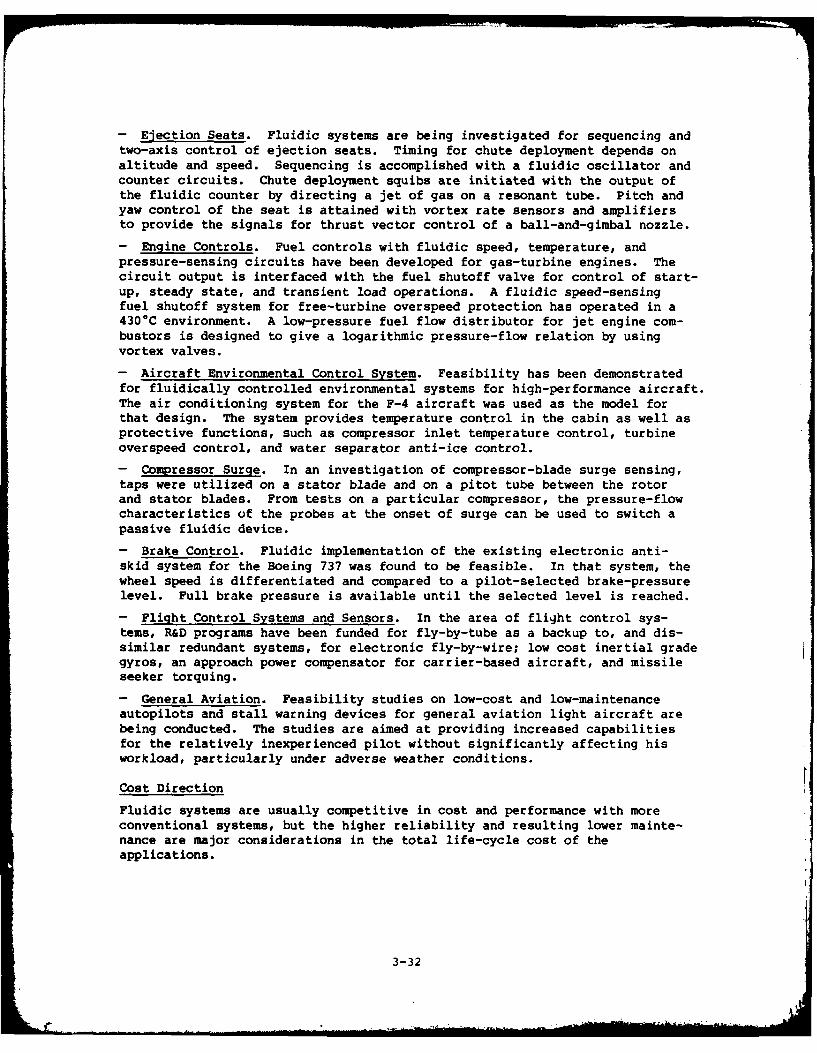
- Ejection Seats. Fluidic systems are being investigated for sequencing andtwo-axis control of ejection seats. Timing for chute deployment depends onaltitude and speed. Sequencing is accomplished with a fluidic oscillator andcounter circuits. Chute deployment squibs are initiated with the output ofthe fluidic counter by directing a jet of gas on a resonant tube. Pitch andyaw control of the seat is attained with vortex rate sensors and amplifiersto provide the signals for thrust vector control of a ball-and-gimbal nozzle.
- Engine Controls. Fuel controls with fluidic speed, temperature, andpressure-sensing circuits have been developed for gas-turbine engines. Thecircuit output is interfaced with the fuel shutoff valve for control of start-up, steady state, and transient load operations. A fluidic speed-sensingfuel shutoff system for free-turbine overspeed protection has operated in a430 0C environment. A low-pressure fuel flow distributor for jet engine com-bustors is designed to give a logarithmic pressure-flow relation by usingvortex valves.
- Aircraft Environmental Control System. Feasibility has been demonstratedfor fluidically controlled environmental systems for high-performance aircraft.The air conditioning system for the F-4 aircraft was used as the model forthat design. The system provides temperature control in the cabin as well asprotective functions, such as compressor inlet temperature control, turbineoverspeed control, and water separator anti-ice control.
- Compressor Surge. In an investigation of compressor-blade surge sensing,taps were utilized on a stator blade and on a pitot tube between the rotorand stator blades. From tests on a particular compressor, the pressure-flowcharacteristics of the probes at the onset of surge can be used to switch apassive fluidic device.
- Brake Control. Fluidic implementation of the existing electronic anti-skid system for the Boeing 737 was found to be feasible. In that system, thewheel speed is differentiated and compared to a pilot-selected brake-pressurelevel. Full brake pressure is available until the selected level is reached.
- Flight Control Systems and Sensors. In the area of flight control sys-tems, R&D programs have been funded for fly-by-tube as a backup to, and dis-similar redundant systems, for electronic fly-by-wire; low cost inertial gradegyros, an approach power compensator for carrier-based aircraft, and missileseeker torquing.
- General Aviation. Feasibility studies on low-cost and low-maintenanceautopilots and stall warning devices for general aviation light aircraft arebeing conducted. The studies are aimed at providing increased capabilitiesfor the relatively inexperienced pilot without significantly affecting hisworkload, particularly under adverse weather conditions.
Cost Direction
Fluidic systems are usually competitive in cost and performance with moreconventional systems, but the higher reliability and resulting lower mainte-nance are major considerations in the total life-cycle cost of theapplications.
3-32
4 C
0Z . 0
o m U
.4 00~ ~ IC0u c
0. ao 1 4 C
0- ilU - -
NO 40 00
U -
01,1 0, 0 4=0. '
9~7 U .
40 A~ so is c
00 a* - .4
M4 .44 a, '.. i
0 U 4. 04 - 0 -C 00 0 I. UC
03-3

o 4%r 0%
00
C 0
8 0
0~1 0 0 V0
c 0 u.
0.A 1c. N
Uc 0 0
00 u - 0 0 Co r
0j 1%. .1 CE ir o
0 w 0 0 1, 0
40 '04 "C C' 0 -C - 0E0
0 ul - 0 - 0 0 0~. 0 ~ *0 0% U ~ 0 4
0C ' .IU 0 4 o
U~.
3-34

04PI) c; .
U. Iu
-w3-35

Code 7
PNEUMATICS TECHNOLOGY
Pneumatic drive devices and control components, such as actuators,power valves, sensors, and control units for mechanization andautomation, are described in this technology brief.
Potential AAAS Applications
Equipment of the Primary Station, Missile Launcher, Special Station, MultipleStore Adapter, and Integration Equipment for the following specific uses:
- Sensing and control for stores ejection/release
- Power source control
- Release control for dispenser stores
- Sensing and actuation for safe/arm
Advantages
- System components are relatively simple in design, installation, andservicing
- Components operate over a low-pressure air supply range
- Operating components are virtually impervious to environmental influencessuch as vibration, temperature changes, grit, dirt, and liquids
- Components do not present a threat to their surroundings.
Disadvantages
- Composite pneumatic control circuits built up using valves, sensors,cylinders, etc., tend to be rather bulky due to the physical size of theindividual components.
- The absence of feedback in control units could create operational problemswhen they are used singly.
Risk
Premised on numerous successful applications of pneumatics, including one byNWC for S&RE, the risk of applying this technology to advanced armament sys-tems is considered medium. Fully pneumatic power sources will necessitateconsiderable investigative efforts to obtain the desired characteristics,such as small size and other critical features, for the AAAS. The likelihoodof achieving these advances in time for ADM implementation is considered low.
Following are two typical factors affecting the risk of applying pneumaticsto advanced armament systems.
- With respect to operational speed, modern pneumatic control units are fullycomparable with the electrical relay type. Pneumatic signals are transmittedat a lower rate than electrical signals, but do not experience the delayscaused by solenoid-valve conversion of electric signals into air signals.
3-37

- Pneumatic system technology has still not achieved widespread recognitionas a subject for engineering education courses. On the other hand, componentmanufacturers have organized courses for designers, fitters, and users, andwidespread use of pneumatics in automated manufacturing processes is commonworldwide.
Trends and State of the Art
Pneumatic technology is characterized by a wide assortment of componentsrepresenting an ever-expanding building kit. This variety of components isdivided into two separate but interrelated design application areas, the"power units" for providing the movement function and the "thinking units"for effecting the control sequences. Power units, better known as actuators,are available in many forms and sizes, and an even greater product variationexists for the thinking units. The latter units are built up using valves intheir many operating modes and configurations, which include lever-operatedand pushbutton devices and the more recently developed modular-moving-partlogic control devices.
In recent years, pneumatic cylinder developments have been guided by thedesire to standardize cylinder diameters, piston rod diameters, and pistonrod thread size. Also, new materials and processing methods have reducedmoving-part friction and therefore lubrication requirements.
The varied forms of modern control valves, such as power valves, sensors,control units, and moving-part logic devices, together with the hundreds ofoptions and accessories available to combine these basic valves, will provideenhanced dynamic control capabilities.
Cost
In applications where the required output is of sufficient quantity, it isusually cost-effective to utilize automated process control systems. Therelatively low cost per function of pneumatic components encourages their usein economically sound designs. It is reported that pneumatic controls stillcommand nearly 50 percent of the dollar volume of all process control systemsdelivered on a worldwide basis.
3-38

I00 z
N 0 0'
4, 0
0 1 C.
0. 0
0, 0
0 u L -
4, 0) 0
t 9m 8 W 0r ) .Z at zU
- q 0 00
4 0) 0 t = 0.
N 0
w M c Cc
cc c 03 C)
0 m >1 Cc . 0 N 0 ' 00 C
0 -0 - 0-O~ ~~~~ 00NC 0 .C a.C
-C a) V0 3 9 4 - 0 - 0 -C
o -*a. C 0 f3-39a
c 0
03 -oc -a Z
c lo
u) g 0 u
41 0
0, ' I 0.
0. c w a. u !Nc v
- *- 9. no c0Q
0 0 41
-4> 0. 4o a o 1
a u 0a.
41 0 412
o -41 0u; ac aN
u c c
0 041 0v
a 0 0 m 4
o a 0 U a44
-41 0 .3-40

0%00
0c r
M m%
0p 'a
0 8 002 41 2u 0 =0
0% 0.-C a o W . -CE- -
00
MC-
*o -0%
i - C 0 -C0% U,% 0 -1
C' 0 VO' 0 0an
0o
C1 V1 0%0% C~O 0
0% 3-39

*11II
i P
0'00 0.
10
0 l 0 -o 0
'C, 00
00 014
0.0
0~ 10 4
4, 4 0-
2 '0
0~~~ >..4,
>
3N 4,41.0 N 0 l
* *4 0 03441

It
Code 8
HYDRAULICS TECHNOLOGY
Hydraulic systems and their components are discussed in thistechnology brief.
Potential AAAS Application
- Power source for S&RE
Advantages
- Components are of rugged construction
- Excellent for high-torque, low-speed applications
- Can be used in harsh environments, such as vibration and corrosion; and inunclean environments
- Digital or analog compatible
- Eliminates the need for troublesome pyrotechnics
- Equipment available for reliable operation to 8,000 psi.
Disadvantages
- System leakage
- Slower control response than electronic
- Higher cost than electronic
- Certain hydraulic fluids are flammable
Risk
Operation at higher pressures has become feasible through continual advancesin technology since the 1940s. Further, hydraulic power sources have beensuccessfully demonstrated for advanced armament systems. The risk ofapplying new-technology hydraulics to the AAAS Program is thus consideredlow-to-medium.
Trends and State of the Art
Hydraulic power sources have been developed for use as stores ejectorsystems. A recent development for advanced aircraft armament systems employsa hydraulic pump connected to an accumulator and a control valve downstreamfrom the accumulator. The valve and accumulator outputs connect to twocylinders (ejector pistons). The pump pressurizes the accumulator and fillsit with fluid for activating the cylinders that push away the stores.
Other hydraulic launching systems employ a hot gas from a pyrotechnic source,or cold pressurized gas to activate hydraulic ejectors (see Figure 8-1).These types of hydraulic system otherwise have a similar principle.
Electrical control units have been developed for controlling the switching,sensing, safety interlock, BIT, and other functions of hydraulic systems (see
3-43

Figure 8-2). Other technology trends in hydraulic systems include thefollowing:
- Filtration Techniques. Improved filtration is accompanying the movetoward higher pressures. Actuators and control elements designed for high-pressure operation have smaller clearances between moving parts than the moretraditional elements. Thus the hydraulic fluid designed to pass through thegaps between parts must be more carefully filtered. Major trends in thisarea include the growing acceptance of matching filtration methods to criti-cal system components through a filtration-compatibility rating for thosecomponents. Within a few years, users should be able to choose filters andestablish maintenance schedules by referring to a compatibility schedule foreach type of component in the system, especially hydraulic motors and pumps.
Improvements are being made in hydraulic fluids and lubricating materialsthat provide safety against fire and cause less corrosion problems fromspills or leakage. These fluids consist of oil-water emulsion and water-glycol solutions, and chemical compositions developed under DoD guidance suchas the synthetic hydrocarbons, silicate esters, and fluorocarbons.
- Components. The trend toward hydraulic flight control systems hasencouraged new developments in components that can operate at pressures up to8,000 psi. These components include:
Hydraulic pumps of piston, axial, and vane designs that deliver higherpressures than previously available. Piston pumps used in aircrafthydraulic systems are typically bent-axis types, built with jewel-likeprecision to deliver extremely high flows at rotating speeds up to25,000 rpm.
One type of axial piston pump used for aircraft hydraulic operationshas a rating of 7,800 rpm at 8,000 psi. This pump uses a 5-micronfluid filter and provides constant pressure and variable delivery. Adesign feature that contributes to this high performance level is theisolation of rolling-element bearings from the pumped fluid, therebyeliminating failures due to anti-friction bearings. Improved packagingof axial-piston pumps has also led to improved flow-to-weight and power-to-weight ratios.
A key design in pumps is the use of pressure-balanced, flexible side-plates that accommodate momentary peak loads and thermal expansion onstartup. The plates are hydrostatically balanced by pressurized fluidto maintain optimum rotor clearance under changing pressure conditions(see Figure 8-3).
An advanced type of hydraulic high-force motor employs rare-earthsamarium-cobalt magnets to drive control valves that actuate aircrafthydraulics. This type of motor, with multiple coils, provides fordirect interface with electronic driving circuitry and eliminates theredundant secondary servoactuators. The magnetic properties ofsamarium-cobalt materials provide for a significantly higher energyproduct than other magnet materials can produce (see Figure 8-4).
Pump controls that match pump output more closely to load demand andreduce the power lost to heat by as much as 60 percent.
3-44
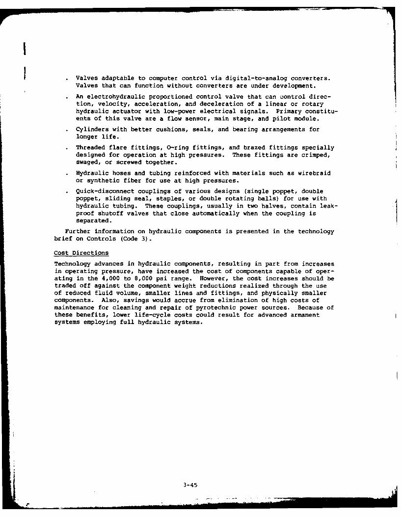
I
. Valves adaptable to computer control via digital-to-analog converters.Valves that can function without converters are under development.
. An electrohydraulic proportioned control valve that can control direc-tion, velocity, acceleration, and deceleration of a linear or rotaryhydraulic actuator with low-power electrical signals. Primary constitu-ents of this valve are a flow sensor, main stage, and pilot module.
• Cylinders with better cushions, seals, and bearing arrangements forlonger life.
. Threaded flare fittings, O-ring fittings, and brazed fittings speciallydesigned for operation at high pressures. These fittings are crimped,swaged, or screwed together.
Hydraulic hoses and tubing reinforced with materials such as wirebraidor synthetic fiber for use at high pressures.
Quick-disconnect couplings of various designs (single poppet, doublepoppet, sliding seal, staples, or double rotating balls) for use withhydraulic tubing. These couplings, usually in two halves, contain leak-proof shutoff valves that close automatically when the coupling isseparated.
Further information on hydraulic components is presented in the technologybrief on Controls (Code 3).
Cost Directions
Technology advances in hydraulic components, resulting in part from increasesin operating pressure, have increased the cost of components capable of oper-ating in the 4,000 to 8,000 psi range. However, the cost increases should betraded off against the component weight reductions realized through the useof reduced fluid volume, smaller lines and fittings, and physically smallercomponents. Also, savings would accrue from elimination of high costs ofmaintenance for cleaning and repair of pyrotechnic power sources. Because ofthese benefits, lower life-cycle costs could result for advanced armamentsystems employing full hydraulic systems.
3-45
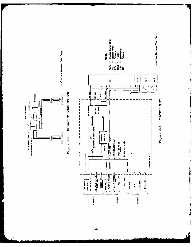
Q
0 u
00
01(JwI _ _ _ _
ic IL
0 I0
- II
3-4
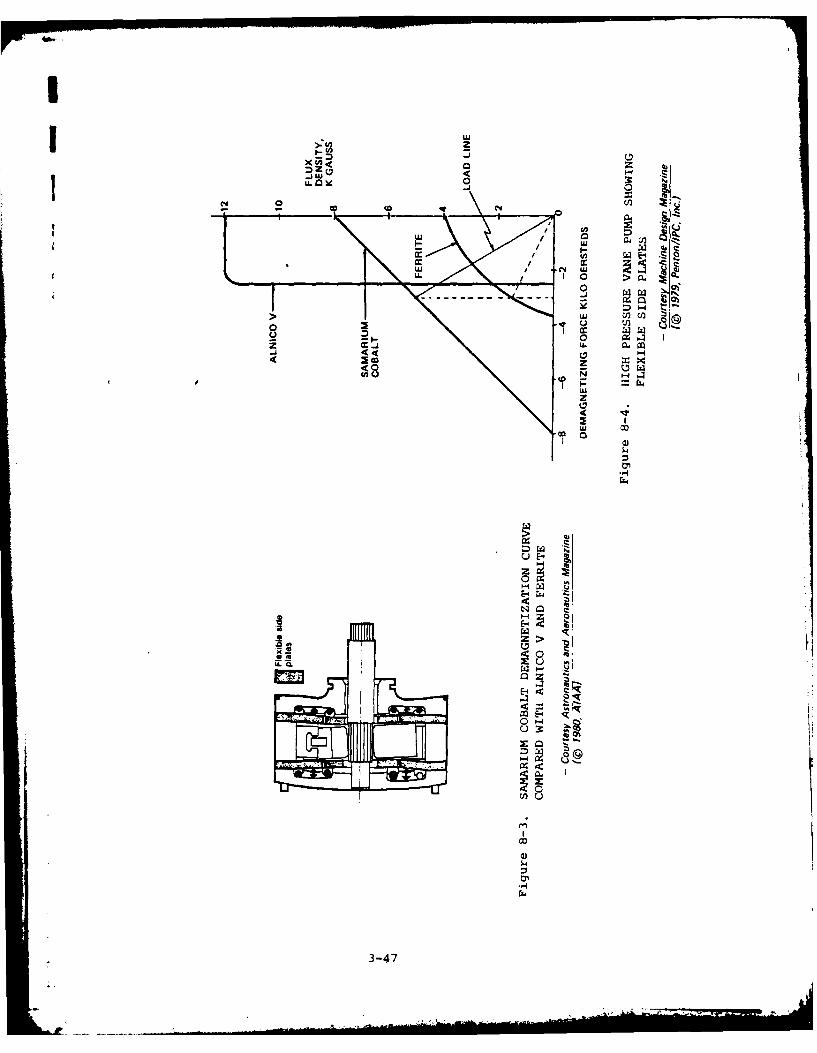
IiLL~zc3 4 '
U 0 3
N~ 0 Cl
LU I, tw c
-1 0- - -. x xLl
< 0u2CfwjtoQ o ".
-J 44
4 44
A ~ (* NE--
rc 2
E--
0 0-4
14Z
3-47 4

1) 0
o a 0I 01
*0 0
00 0
10 U3 4
0k w~ o.M na
Go 0011
0 c V)E Iau0 t
0.~4 0 0
0~c 0 0
ri- - U> V 0 -CC
- . . 00
2-0 0 0 ~0U '4~~1 -C 0
0 0 0 .
c Cm 0 M 0c ICi 0
0.. 0
0 0r
=00
0 0 -

I0C 0
o1 0
04 0,
c0 O4
4144
or 04 go
c4 41 1 0.
0 u 0A 2 41
00 hiC.) 44
a >.MU In "41 Co
3-4

Cc
to C
0 01
0 m 4%
E4 w % -C8 3 .
s0 N. 0 0 1
cc e - 0%
0. -a0
*v 0%-0 %
0%00. 0. 0.> O,
2c an 0
C a >. u I.
00
~..o 0 - 0 41 0
0%0 a -u0 4 % ' 0" C7 4,%
0' C . . .
0- - % a % .. .
oa, 63- 0- a. a,- % 0c% a, a% 4 -0. a-w C .
a,~ 0 0a .. 1a,4a,,a
a- 0
3-50

S
I
C
0 a,
a,
a,.
* a, a,a, '4. a
>, a,a,, 3 0
0a, a,. U
UV a,
a, - 4.
3 3
0~ - a, I -C a, 0 0
- C F. CU 0 4. a,-
- U C -0a a, a, 0 01 4'
3 3 01 U Co a,~ U aI-~ 0. 0 -
-~aU V -
- ~ U 4.'U al . V
0 Ia' M ~.a,. C - - 'V
3 01 - 1~. 3 3 U
a, U . -I .~S U
-V a,a,.3 .4. a,.
a,~ 014.
- a, - ~~.. .3 - 0 I - -- - 0Z 01 41 U - - -- U U
0 'a am o a. I~ a SW~ ~~ a,~ - Ua, C '0
I3-51

I
Codes 10 and 11
MATERIALS AND MANUFACTURING TECHNOLOGIES
This technology brief describes materials, such as composites andalloys, and manufacturing technologies of particular interest tothe AAAS Program.
Potential AAAS Applications
- Conformal carriages
- Aircraft hardpoints
- Modular unit suspension equipment (MUSE)
- Multiple stores adapters
Advantages
- Composite materials are of lower mass density than pure metals or alloys,and their use where possible in aircraft structures could lead to substan-tial weight reductions, with attendant fuel savings and aerodynamic bene-fits (see Figure 10-1).
- Reduced levels of stress, fatigue, and chemical corrosion are evidencedwhen composites and new alloys are used. Further, the composites and newalloys exhibit higher strength and modulus (Figure 10-2), lower density,and improved fracture and fatigue resistance.
- A rediced radar cross-section is associated with the lower density of thecomposites and new alloys.
- Advanced manufacturing processes such as laser welding and superplasticforming/diffusion bonding DSPF/DB can be utilized to yield less wastedmaterial, decreased use of energy, and reduced labor requirements.
Disadvantages
- Composite structures are subject to absorption of moisture and consequentreduction in compression strength. For several military aircraft applica-tions, however, this condition has not been considered a problem.
- The initial investment in manufacturing technology is expensive, and canresult in higher costs than anticipated for prototypes. However, projec-tions indicate that the cost of composite structures will decrease asmanufacturing experience grows.
- Some problems persist, such as nonrepeatability of bonding due to impropercure, and are being addressed by industry and DoD. Methods for non-destructive testing of composites need to be refined.
- Potential problems related to lightning effects, flammability, and safetyare yet to be resolved for composites.
Risk
The risk in using the state-of-the-art composite and alloy materials foradvanced armament structures is considered medium by virtue of demonstratedsuccess in F-14, F-16, F-18, and SR-71 applications. Two successful NATOapplications of composites are reported for S&RE.
3-53
£, , l | .. . . . .'. . ... . . ..

Trends and State of the Art
- Composites. The trend is toward greater use of composites in militaryaircraft structures. The major composites used are a matrix-like resin suchas epoxy or a polyimide reinforced with carbon (graphite), boron, and/orKevlar fibers. Polyimide structures promise better repeatability in manufac-turing than epoxies. Kevlar composites, while not quite strong enough for
primary structures, are receiving significant attention as a substitute for
glass fibers in the fabrication of secondary structures.
New composites are being developed that contain alumina or silica instead of,
or in combination with, graphite and Kevlar.
Automated manufacturing for composites is expanding in the areas of robotics,programmed automatic cutters, programmed handling, automatic dispensing, andautomated laminating. Automatic video inspection and automated clean roomsare becoming standard industry practices.
- Alloys. In the manufacturing of aircraft structural elements, the trendis toward using aluminum alloys containing lithium and magnesium. The alloys(e.g., 2224, 2324 and 7150) are of lower density and have greater stiffnessand strength. Manufacturing methods such as hot isostatic pressing andisothermal rolling associated with powder metallurgy provide improvedmicrostructures. The rapid solidification rate (RSR) aluminum alloyscontaining iron, molybdenum, and chromium are gaining considerable interestfor aircraft structures.
New titanium alloys consisting of special combinations of metals such as
chromium, aluminum, tin, iron, and vanadium have emerged as promisingmaterials for aircraft structures. One alloy, CORONA-5, offers highstrength, low density, and improved corrosion resistance. Manufacturingprocesses for fabricating structures of these alloys include cold rolling andforming, age hardening, and superplastic forming with diffusion bonding.(See Figure 10-3 for comparison of SPF/DF vs. conventional.) Electron-beamwelded forgings of titanium alloys are becoming prevalent in aircraftapplications.
High-strength steels such as the AF1410 (containing cobalt, and nickel), usedin the AFAL LOCOSST program yield weight and cost saving advantages relativeto other alloys and metal (see Figure 10-4). In particular, the strength andtoughness of steels containing such elements as vanadium, silicon,molybdenum, and carbon make them desirable for use as fittings, pins, andfasteners in future aircraft.
Some physical characteristics of the above alloys and composites are shown inTables 10.1 through 10.3.
Bonding Techniques. The success of the Air Force in the PABST program andcommercial acceptance of adhesive bonding represents a significantadvancement in material technology. Weld and diffusion bonding also showpromise as rivetless bonding approaches.
Cost
A major cost reduction realized by DoD and industry, through the use of thematerials and processes described above, results from reduced weight and theattendant decrease in fuel requirements. Other cost reductions noted in theliterature relate to less waste and less human involvement in manufacturing;and ultimately, from using readily available materials such as carbon ratherthan dwindling resources such as titanium. Typical cost savings from usingcomposites and new alloys can be observed in Figures 10-1 and 10-3 andTable 10-3.
3-54
. . .. .. . . . . . . . .. . . . I .. . . . . ... . . .. - -" - -1 1 -, ..

LnL
0 r0+E-~ o-
p4 0
2U a -- 7-. z -I 1
(A0 vi--: -- l
(nn
I-C ew
Z. wZ2
CL X
4~L z
~0
LLW 0
x~ z E-4 -
WD 0 0 Ei
Uu8 0 w zW E- >
o' 11-. (Aa
t u
(A z
CL:
3-5 10 LU m
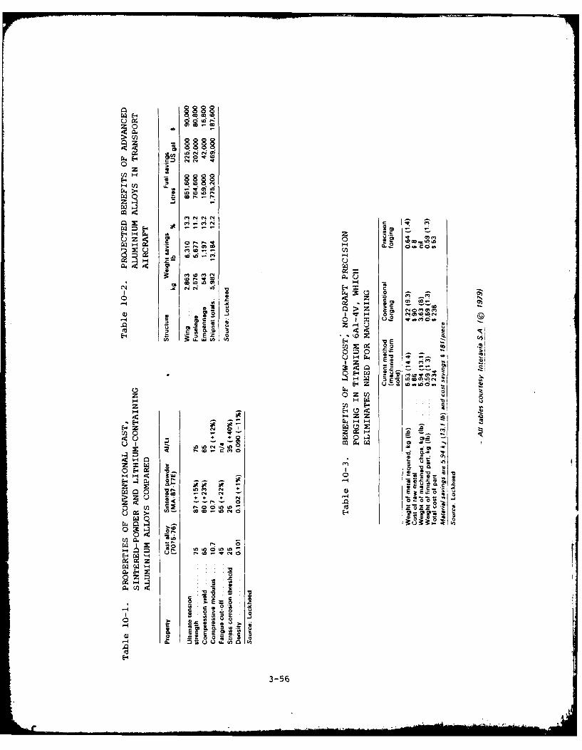
E-4z
HH
-4 H .-
cm La 60 0C4 04 Zo-4 x
U ~ 2z . 2
H 0 01 oC
>z 08
5 z~i uU. Huz 0) (
C E-4
z U)
N 0'
LI)0 ~
H6 Hn ci
- to -C(
M Ch
I- 00
&4
< - tZ
4 ECEZ; j WE0 8 ~ o~ .2-0 La ~ ~ fl l
toL) LoU
EW3-56

Is 11UU
fx Co'
1. 00 cu
go a1
-14 0~ 01 U
0~- ci~ Ca
C 4 )
~ go
A) A
oaa A. tS -o t4 .0 - - 0
Z So d~ 0)2to
at 19
at 3-57

0 . CL
a, - 1
a, c,
0 0 ~ 0
14 w
a, 0
a,~~ >0 , C0
12C -F a,. -
~ j '0 , '3-583

0
U
Ic a
U3-5

00
C. 0
1 0J to0
0. 3- I
4, 0 0
Inw o a,
w 0 0 Im. o.wl
- JJO 41 -
41 0. - U -
U 0 0 0 0 0.(
Cv 0 -C 0 V
z 100.
O~ ~~ 0 00 .0~~~ 0 5 0I 0 I0 0 1
00
0 0 wa,
*~( A ~ 4 0 0
w -C a
0 -
Ct
CL b!
0. 0.C at
0. 0
U o -
0 0 1 0' 0 0Z .. I
- c i . 0u
00 03 0 0

b. Go it 06
0 00
C a CC
0 11U 0.A
r 'A 0
L0 >1 Cc 0 C 2
41 00. LI q 0z 0u
0 0 - c
C l( > 0 -.
10i 0 4 00 0 0
0 -3 10 0 0.
I c 2 0 0 0
0 220 0
U 2 43 a- 00 C 'a, 02 0,
0 C C- . 0 10 4 -
-~ a a
0 & 03 U61
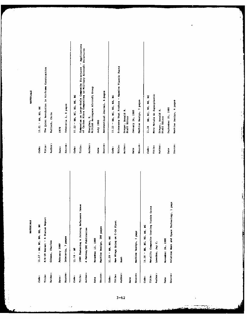
0
0~
u-
41 C
o0 m
qc 00coo
0
0 Co. 05
0 0 0-
0 0-C 0 w 0
-- 0 -C zC~~~ 4-1~-
*ff 00 u.0
o o. -
m - 0 0 10u 0In U 0 ~ U . .
0 - 00 0 C C. ~IJ 0 S OM S. A 0 0 . 0
0= - -00 = . C
- a U 00 .. ~ C 1' II 01 0* 0 toN - Al 0 N g.U =41 ~. 0 N ~ 0141 0 . 11
42 0 42I04 - I. U 0 C 0I 0 0
0 ~ ~~~-62.l ~ L4

K I
I
i
U
S -~
*1 U 4
-g o
4, U
0~ -
[~ aI~O 4 I..
A~- U
U-.
C-- a- a
~ 006 0 -'-- a -~ ~~q
aU
* -- ~,-* U ~ ~ aa 0=~ *~ * N
Erno -~ ~, a' S..' u'~ -
Ili ~-U U -I'. *,fl- ~U - 4
* ~Ua ~- - -~ "
.. ~
2 ~4
3-63

Code 13
PYROTECHNICS TECHNOLOGY
This technology brief presents information relative to the state-of-the-art technology for solid-propellant actuated cartridges andpropellant materials, and their application to advanced armamentsystems.
Potential AAAS Application
- Power source for S&RE ejectors
Advantages
For newer applications:
- Cleaner systems, lower maintenance, longer system life
- Improved safety for projected EMR/EMP environments
- Simplified design, increased flexibility, and increased reliability
- Reduced life cycle cost
Disadvantages
- Limited operational experience
- Need for advanced development and more extensive reliability testing ofconcepts and prototypes.
Risk
Electrically initiated power cartridges have been used extensively for bombrack and missile launchcr ejectors and other stores dispensing applications(countermeasure rounds, sonobouys, etc.). Except for the aspect of laserinitiated cartridges and advanced miniaturized inductive coupling,technologies described in this brief represent innovative concepts of low-to-medium development risk in providing advanced ejector power sourcecapabilities.
Trends and State of the Art
Efforts are continuing in industry to develop propellants that can operatereliably at high altitudes and low temperature and produce clean products ofcombustion. One material, designated as IS-29 and developed by SpecialDevices, Inc., has a flame temperature of 12850 Kelvin and produces a high-pressure gas yield of 4.3 moles per 100 grams of propellant. The material isvery stable from -65* to +165*C, with no problems of aging, decomposition, orstructural changes. High humidity does not affect the propellant character-istics. IS-29 has a highly uniform burn rate at temperature and pressureextremes, and contains no corrosive gases such as HCL that would affect sur-rounding armament structures.
3-65

- Cartridge Output Cleanliness/Self-Contained Cartridge. Several approachesare being pursued to provide cleaner cartridge output toward a significantreduction in, or the elimination of, ejector cleaning. These consist of thefollowing:
1) The development by the Navy of a new series of stores ejection cartridges,designated as CCU-43/B, CCU-44/B, and CCU-45/B. These cartridges are con-siderably cleaner than the Navy Mk series cartridges (Mk 2, Mk 124/125,etc.) that they replace. For the CCU-type cartridges, cleaning intervalshave been extended to 50 firings in several ejectors. These cartridgeshave been qualified, released to service, and placed into production.
2) The development of a filter that can be inserted into the breech system,ahead of the cartridge, to significantly reduce particulate matter in thedownstream ejector components. NATO armament systems currently employsuch filters. A U.S. source has also been developed for such a filter.
3) Ejector-system vent designs that provide rapid external venting of car-tridge exhaust at the end of stroke, purging the system of particulatematter. Such a design utilizing a cartridge in a piston-actuatedhydraulic ejector system has been demonstrated to provide more than 500firings without cleaning.
4) A completely self-contained telescoping cartridge for use in amechanically linked/hydraulic ejector. In this design approach, thecartridge case is sealed and remains sealed after firings, telescopingduring firing and transmitting a tailored force-time profile to a movingpiston. Since the cartridge remains completely sealed, no gas productsenter the ejector system and internal cleaning is therefore completelyeliminated. The Naval Ordnance Station, Indian Head, has conductedexploratory development of this concept, demonstrating functionalcapability of attaining a 24 ft/sec velocity with a 500-lb store in amechanically linked/hydraulic ejector prototype. A condensible propellantis being developed to result in low (50 psi) residual pressure uponcooldown. Exploratory development with the condensible propellant isexpected to be completed by October 1981.
- Electric Initiator Safety, Reliability and Cost for Increasingly SevereElectromagnetic Radiation/Electromagnetic Pulse and ElectrostaticEnvironments. Current approaches utilize a 1-amp, 1-watt no-fire cartridge(CCU-series) in conjunction with proper firing-circuit shielding/connectors(and where necessary, firing circuit filters) to prevent induced current andprovide the necessary degree of EMR protection. The following additionaltechnology areas have been/are being pursued:
1) Planar Bridge Element - This design provides a low-cost means ofprotecting the bridge circuit from extraneous electrical charges. Multi-pin configurations (versus the standard center electrode/case groundconfiguration) of the Mk 17 type have been developed. A test program hasbeen conducted at the Naval Ordnance Station, Indian Head, which hasdemonstrated design feasibility.
2) Inductively-Coupled Initiator - This design approach eliminates directelectrical contact between the firing circuit and the cartridge bridgecircuit. Instead, the firing circuit contains a firing head with a drivercircuit that would provide a magnetic coupling with a receiver in acompletely shielded cartridge. This approach eliminates the need for
3-66

Ir
I
bulky, expensive filters and other firing circuit features that would berequired in the more severe E4R/EMP environments. The ARBOC counter-measure rocket launcher contains an inductively-coupled firing circuitdemonstrated to be suitable in the shipboard environment. To be con-sidered for S&RE ejector applications, however, these components must besubstantially reduced in size. An exploratory research and developmentprogram has been conducted by the Navy in which a miniaturized con-figuration suitable for use in S&RE ejectors has been developed. Initialtesting has indicated suitability for initiation of low-power squibconfigurations. Development is continuing over the next 2 years to obtaina configuration that will meet all service environments and demonstrateprotection in the EMR/EMP environments.
3) Laser/Fiber Optic Initiated Cartridge - This approach would completelyeliminate any electrical/electromagnetic interface with the cartridge.Basic feasibility of initiating cartridges directly with a laser sourcehas been demonstrated. The development of low-loss fiber optic lines hasallowed initiation of pyrotechnic materials to be demonstrated over a linewidth of 300 feet from a compact laser course weighing about 4 pounds.Development/demonstration of this concept with hardware applicable to STSis planned over the next 2 years in the Navy exploratory research anddevelopment program.
Cost
No specific data relative to the cost of pyrotechnics was observed in theliterature. However, by eliminating and/or reducing maintenance actions as aresult of cleaner systems, reduced life cycle costs can be expected.
3-6
; 3-67

C-,l
lz
-4
0
'4
CL U)
00
U.)
6a --- 3 4
tnc L
4( - =
WA 4:
0.
cc CL 0z
.; 0 tp
3-68 t

IIcc 0 2)0g
0 3(30 0 u
a t0
0 1. z 18 1 1-C U 0 U E
aa to.
41 0 0go
UC o . 2 t
m -. v- - .0
- 0 Cj0- to a2
30 ot *
a 0 0 o.3 'o 0 o .2 3u3.t
"3c M (t O " 2 3
to . 2to,'3. 3to69
- ~ o . 0 ' . 0'm2o2

AD-A107 b8G ARINC RESEARCH CORP SANTA ANA CA F/6 1/3TECHNOLOGY OVERVIEW FOR ADVANCED AIRCRAFT ARMAMENT SYSTEM PROGR--ETC(U)MAY 81 H ROSENBERG, K BRAMAN, R BROOKS H60530-BO-C-0270
UNCLASSIFIED 1789-01-1-2406 NL
3 3IfIIIIIIIIIIIffIlllllllll
ElEEEElllEllEIIIEIIIIEEIIIIEEIEEEEEEEEEEEEEIIIEEIIIIIIIEEIIEIIEEEEEEEE

00
C. 0
U 0
00
00
- 4
-C o
4. 1
V 0 0Co
40 60-4' 4' ).r
4' ~ a
ma 0A g I 1 -0
10
-- 2 012- 2.
3-70'

Codes 14 and 16
RELIABILITY AND SAFETY TECHNOLOGIES
This technology brief considers new techniques, methods, andanalytical concepts being implemented to improve reliability, main-tainability, and safety. No specific information is presentedrelating these technologies to S&RE in terms of advantages, dis-advantages, costs, or risks of application. However, this trendinformation can provide general guidance in the development of AAASR&M and safety programs.
Potential AAAS Applications
Prior to the early 1970s, few military avionics acquistion programs werebased on coordinated reliability elements or dedicated reliability disci-plines. Reliability design elements were usually limited to classical engi-neering "best practices". Subsequently, the first clue to inadequate reli-ability design was seldom evidenced until system deployment. Dedicated reli-ability efforts were then often remedial in nature, consisting of selectivecircuit redesign with occasional empirical tests for assessing the effective-ness of design improvements. That is not to say that the reliability special-ists were not active - many of the reliability disciplines recognized todayoriginated well before 1970. However, the recommendations of these special-ists were simply not widely followed.
In late 1973 and 1974, top military management initiated sweeping reformswith the intent of elevating reliability performance to critical parameterstatus. Nearly every existing reliability analysis and discipline that prom-ised a positive return on reliability performance was drawn out, dusted off,and thrust upon the avionics community. Thus, DoD Directive 5000.40 of July1980 establishes the policies, responsibilities and guidelines for R&M of DoDsystems, subsystems, and equipment that apply to all military departments anddefense agencies. The directive further provides DoD standard R&M terms, andmandates R&M accounting using terms related to operational effectiveness andownership costs.
The list of reliability disciplines is long and many are overlapping andredundant. Some are limited in effectiveness for certain technologies.Others yield limited benefits for certain field applications. Many arefamiliar to most avionics developers as informal design procedures. Nearlyall are expensive when formally documented. Not all reliability disciplinesare cost effective on all avionics development programs. The following twostate-of-the art disciplines may be appropriate in providing R&M requirementsguidance regarding S&RE development.
- Integrated Testing. A typical development test cycle for a complexavionics system spans 2 to 3 years. It is possible to maximize reliabilitymaturity with minimal cost and schedule impact by utilizing the test time anddata for reliability development. This integrated test philosophy is beingimplemented in current engineering development test programs to achieve reli-ability growth.
3-71

- Combined Environmental Reliability Test. Combined environmentalreliability test (CERT) facilities have been recently developed with improvedcapabilities for simulating the dynamic combined environments to which intern-ally carried aircraft equipment is exposed in modern high-performance mili-tary aircraft. This test philosophy identifies an effective, low-cost methodfor the integration of operating environments and reliability assessment tests.
Safety
The long-recognized need for designing and building safety into aircraftsystems is the subject of numerous government directives, most notablyMIL-STD-882, Requirements for System Safety Programs for Systems and Associ-ated Subsystems and Equipment. While the principles of system safety shouldbe applied throughout all acquisition phases, the most important phase isundoubtedly the conceputal, when the Preliminary Hazard Analysis (PHA) shouldbe conducted. Following are two examples of the application of PHA tech-niques to obtain required safety levels:
• A model was developed by the Army Armament R&D Command for evaluatingthe safety and reliability of electrical equipment in a lightning environment.
* The advent of LSI circuits for airborne computers has made the use ofmuch higher levels of redundancy and replication economically possible. Econ-omical use of replication is making fault-tolerant systems feasible, and moreand more applications for safety critical systems such as active flight con-trols can be expected. In turn, the opportunity to use massive redundancy,
fault-tolerance, and reconfigurable systems is stimulating the development ofnew analytical tools for establishing the safety and cost-effectiveness ofthe levels of replication proposed. As an example, one manufacturer hasdesigned an advanced SMS based on a reconfigurable series/parallel duplexcontrol system concept (Figure 14-1). That system is intended to meet thesafety/reliability requirement that no single failure will cause an inadver-tent stores release, and the need to achieve a high certainty of successfulrelease of stores in time of war.
3-72,1

za z
4>
0 c j
dU
CLi
b. II 1
z 0
ga8 uIV
wu 'In
us
U3-7

a DU
0 S4
* 2U
4. -00
* -6go a
K .4 a.
a.. 004.
0 U
- a..
- b3-74

IC
IrI
go 'A A2 z 'S
0 U6
V- J3 a,1- .
r 4
it Ai -m 11
al de -2 Z4-

*.4 0
oC 41A
.4l
WO 1., 4
0 0
Cc u
00
.4' r
a~EPO g 8
a ,5~g . ~ 3-76~

tIcIc
Ur
* -C
La0
-) Mo A
w Im .4
IN 2
3-7

I
3.2 STORES MANAGEMENT SYSTEM
3.2.1 Technologies Investigated
The technologies investigated for the SMS portion of the AAAS are aslisted below, each preceded by an assigned code as discussed for S&RE in Sec-tion 3.1.1.
26. Computers 34. Large Scale Integration
27. (Not used)* 35. (Not used)*
28. Controls/Displays 36. Memory
29. Data Bus 37. Packaging
30. Electrical 38. Reliability
31. Electromagnetic 39. SoftwareEnvironment
40. Switching
32. Fiber Optics41. Lasers
33. Languages
3.2.2 Technology Matrix
Table 2 is a coded matrix for SMS that relates the applicable SMS tech-nologies investigated, WBS elements (from Figure 3), and technology informa-tion sources. The information in Table 2 is interpreted the same as dis-cussed for S&RE in Section 3.1.2.
3.2.3 Technology Briefs
Technology briefs for SMS follow, presented in the order listed in Sec-tion 3.2.1.
*Left blank intentionally for purposes of potential expansion of technology.
3-79
'I

C -0
10 T., II
* O A '110 .
T~ v - N I N I_ _
E- *0.
3-80~

318

Code 26
COMPUTERS
The application of computers to the AAAS is covered in thistechnology brief. Computer architectures and fault-tolerancetechniques are given particular attention.
Potential AAAS Applications
- Process control equipment
- Aircraft interface equipment
- Stores station equipment
Advantages
- Use of computers in advanced armament systems allows the systems to func-tion at a higher level of sophistication while minimizing crew workloads.This increased sophistication yields a flexibility that allows armamentsystems to readily accommodate numerous types of stores and variations inoperational and mission scenarios; and permits possible use of standard-ized computer elements in different types of aircraft.
- The advent of microprocessors supports the incorporation of distributedprocessing and fault tolerance techniques in advanced armament systems.
- A centralized computer architecture tends to use less software and hard-ware than distributed architectures. Centralization facilitates the inte-gration and management of system development, and forces a high degree ofstandardization of application programs and documentation.
Disadvantages
- Support of computer-oriented systems requires specialized test equipmentand highly trained technicians with knowledge of both hardware and software.Software is inherently costly to document, test, and maintain.
Risk
As is true for most technologies, the risk associated with the utilization ofcomputers increases as the state of the art is approached. Minimum riskwould be incurred by using a proven minicomputer such as the AN/AYK-14. Thisapproach, however, would not allow the exploitation of advantages inherent to
the more recently developed minicomputers, microcomputers, and microprocessors.These advantages include reduced size, weight, and power consumption, withpossible increases in speed and addressable memory.
Trends and State of the Art
- Minicomputers. The present Navy computer for airborne applications isthe AN/AYK-14(V), XN-l configuration. This 16-bit computer addresses up to128,000 words of memory, operates at 675 KOPS, weighs 55 pounds, and requires1,600 watts of input power.
3-83
& ,j

Other 16-bit military airborne computers in development are targeted tooperate at throughput speeds of up to 800 KOPS, to have an increased I/O capa-bility (up to 64 channels), and to be lighter and consume less power than theAN/AYK-14(V).
Also in development, with availability projected in the mid to late 1980s,are 32-bit computers with a throughput of up to 2,000 KOPS and with approxi-mately the same size, weight, and addressable memory capacity as the present16-bit computers. The 32-bit machines are projected to have reduced powerconsumption, down to 100 watts.
- Microprocessors. The leading edge of MOS microprocessor technology isrepresented by such 16-bit devices as the Z8000, 68000, and 8086. The trendfor the 32-bit processors is to bias the instruction sets toward implementingHOL compilers to reduce the software costs of large programs. The languagesmost frequently targeted are Pascal and Ada.
Single-chip microcomputer devices are established in the 8-bit controllerarea and are developmental for 16-bit microcomputers.
Considerable development is underway in the area of 8-bit CMOS microproces-sors to take advantage of the low power, high noise immunity, and toleranceto power supply variations offered by this technology.
As an example of what can be achieved using a 16-bit MOS microprocessor toimplement an airborne computer, some prototypes have a throughput of 350 KOPS,four I/O channels, weigh 6 pounds, and consume 50 watts.
Another microcomputer, the "i APX 432", is a 32-bit device implemented as athree-chip set (a two-chip main processor and one-chip interface processor).This system employs microcoded firmware and is programmed in Ada high orderlanguage.
- Computer Architecture. Microprocessors are being employed to an increas-ing extent to help satisfy requirements of a greater degree of subsystem-to-subsystem communication. Serial architectures of the past are being replacedwith architectures that allow parallel flow through independent processors.The most likely architecture to evolve during the 1980s is a combinationhierarchical-distributed system. For example, several subsystems may be inter-faced independently with the operators, making the system appear distributed;while a single executive may be employed to provide common logical interfaces.
The use of distributed architectures (Figure 26-1) has given rise to theneed for inte:element communication. Distributed architecture will transferdata from one element to another through multiple paths via multiplex databuses to enhance system reliability.
Skewed processing, a new computer architecture, incorporates distributedcontrol functions and lends itself to implementation of fault-tolerant sys-tems. That is, any processor that fails can be logically removed from thecircuit and the remaining processors will distribute the task equally amongthemselves.
- Fault Tolerant Computing. Increasing attention is being given to the useof fault-tolerant computing techniques to achieve higher levels of safety andreliability in aircraft armament systems. At least two architectural con-cepts for fault-tolerance software are in development (see below). The
3-84

II
fault-tolerance systems employ replication of computing tasks among processingunits. Error correction and system reconfiguration are performed by the software,and thus a single failure can be tolerated and any subsequent failures can betolerated after reconfiguration.
The two fault-tolerance systems referred to above are the Software Imple-mented Fault Tolerance (SIFT) and the Fault Tolerant Multiprocessor (FTMP)systems, products of flight-control research by NASA. The SIFT system uti-lizes a number of CPUs with associated memories and I/O processors, allinterconnected by redundant buses. The software of the system allocatesprocessors, memories, and buses to the total computational task and, in caseof failure, reallocates these resources. FTMP uses triads of processors,memories, and buses, with a number of triads functioning as multiprocessors.Each triad element executes identical programs in synchronism, and a hardwaremonitor notes all results of the triads appearing on the buses. The triadscan mask failures, detect faulty modules, and take over for failed items.Functional diagrams of these systems are shown in Figure 26-2.
Cost Trends
The cost of developing a computer-based system is graphically depicted inFigure 26-3. As can be seen in this illustration, the cost of softwarerepresents the majority of the cost of development, with this ratio increas-ing with time since the trend is that software development costs are increas-ing at a rate of 12 percent per year while hardware costs are decreasing by20 percent annually.
3-85

I g
C.a.
0~
OOZL 0 C..
IiI
H 0
E4H
m 4
3-86
4E-

wUL
u~ 0- 0z .,-:
______ _____E-1
E-4 ~~z
0 -ch
LL00
00
,4
0 Cn
.LSOO IN3LWdO13A3(a
3-87

o U
-y.
40
oz 0
I, '0-0 0 C
0 >% . 0A4d 0 c w,-04
C CL CC r
0 As
C 0CZ.00 0 04 > 0
C1.67 16 E-00 C
0 0U
4,3 0 C
'A -4
U) 10, . 2 C
0.. 0- 1 4 0% 1 4, -4, 0 1 ' C~b- 04 a' v
4, 0-.U * , . U4 0U4to- C 4, - 4 . ,4 - ~ 4 , - C 4
00
0~~~~~~~ 4- 4 0 0 - 4 0 01 0 4 1 U 4 0t0
a. 3
ZO01 - Aq o 0
0 0'u1 0 E "4
0 , .0 M. cc -U.
F. - A 10 ,4 0 4
As N - - -88.. As 0

40 or-
w4 0
00
- .4 0- 0 .
cc 0 0 444
, Uc o- -
44 0.
4,or 4444c
-. 0 44a'a
0 a MW
0 N
0 . . -
00 0 u
444 2
444 04. .
4 ~~ ~ 0 -u C - J040 - O4 - .
14 U >01 .
41 0 4 0 U * 4 0 0 . 4
44 -C 4 4 - C 'cc 4. 4 . 4 4 4 C
.4 3~ ~ 3-89

-C
0 4
4 c
4,
02 0 cd, a,24
0 z
a.
4,U 0.4 4
011 4
Me -0 0.- 0-C
w .3 0
4, 7. W,0 C
-C 0. 40 , -
- - U C 'A
-~ i -. z i 4
o1 E,4 0 4-C 3C Do-~ 4, --0 * d 4,
- 4, .4, 4 U~ U 0 4, h34,90
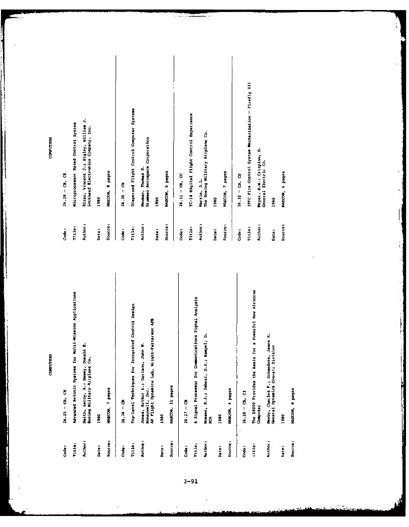
00
n 0 u41 00 C .
0 4 0. R
400
0 . 0
0 Ccc 0
S0 (n IV
C 4.C
0~~ -U 0 4C2 -
00 .C*01 0 .
0' cc lS IV . - . 0
02~ ~~ 21 41 0 ' 0 .- - 0 a a 0
0" . a -8
U 83-91
MEN&& 0.C .I

4-0.
0 0 . 4
r 0 00 0>
44 44 -C 44 r.£
00 044.
0o - - C 404 0e rC D 0 -.0
~~2 0 4 00
C C w 44C C, 2
m . c 00 w V 42 0 co C .00'0 '
-~ ~ ~ - 6C 0
0.4
'4.~ -u~. - .o - r - UC.
42 @
C
00o
"I co8C
2-A-

0 C0
0 0
040. 0
o
0 00 0' 0 1 W
0 0-
-C 00 'A I- - M-
EE
0 - C
31
0 00
0 -0 & 2
S0 m04 0.
- ~ ~~~~ 'L0 0 0 0'NI *C
A m o. - 0
-C 1, 0 0 -0
o 0 3
0 0 0 .~C~1 81 4. v.*0 ~ -
*~~ I. -C .In * - ZQ .1- ~ - - o '.8 c
'0 - ~0 ~ 0 - 01 - 0 0 C) 3-003

Code 28
CONTROL/DISPLAY TECHNOLOGY
This technology brief on control and display systems gives emphasis to CRTsand digital controls currently employed in military aircraft.
Potential AAAS Applications
- Controls of the conventional type, such as bomb buttons; and controls forselecting modes.
- Displays such as discrete indicators and multifunction types.
Advantages
- CRT displays are still regarded as the best available means of displayinggraphic and alphanumeric information. They have the highest resolution,contrast, and addressability; and the potential for full-color display(see Table 28-1).
- The F-18 multifunction CRT displays have reduced pilot scan time andstress, and have evidenced improved reliability and reduced life cyclecosts relative to other display systems.
- Flat panel displays such as the electroluminescent and liquid crystaltypes require low operating voltages, provide direct digital compatibil-ity, have high accuracy and edge focus capability, and are very good forsmall and large area focus (see Table 28-1). Flat panel displays alsooccupy less volume and are more shock resistant than CRT displays.
- LED displays are optimized for alphanumeric applications.
Disadvantages
For multipurpose display applications, flat panel displays are still emergingand have certain disadvantages (see Table 28-1). However, it is the opinionof experts in the field that inherent disadvantages of CRT displays (e.g.,high operating voltages and susceptibility to physical damage) will result intheir eventual replacement (in 10 to 20 years) with flat panel types.
Risk
The risk in using multifunction controls and graphic CRT displays is con-sidered low due to the success and benefits observed in such applications asthe Navy F-18 (see Figure 28-1) and the Air Force F-16 aircraft.
Flat panel displays are of low risk for alphanumeric applications not requir-ing the display of graphic information. However, flat panels are consideredof medium risk for graphics applications because that technology has notmatched CRT displays in terms of contrast, readability, and cost.
Trends and State of the Art
Displays. (See Table 28-2 for projections of display implementation.)
- CRT displays are experiencing continually greater usage in aircraft arma-ment system applications. Advanced CRT displays contain microcircuits
3-95

that perform processing, I/O, and scan generation functions. In essencethese displays are intelligent terminals capable of presenting bothalphanumerics and graphics. One example is the multipurpose display indi-cator on the F-18 aircraft (Figure 28-2), a graphic terminal that displayssuch information as aircraft speed and weapon status. Superimposed onthese displays are radar data from sensors (e.g., mapping and attack).
- A recent development in heads-up display (HUD) systems is one that uti-lizes holography to provide a wider field of view and improved brightnessfor symbol presentation. Relative to other HUDs, the instantaneous fieldof view for the new system is 35 versus 17 degrees azimuth and from 20versus 11.5 degrees elevation. In addition, there is a reduction in thenumber of spurious images and reflections in the holographic system.
- Another CRT system is the horizontal situation display (HSD) in the F-18A(Figure 28-2), which combines a full color, moving map display with CRToverlays. This full color map capability is derived by optically projecting35-mm color film through a beam-splitting mechanism in the HSD.
- Although new methodologies for improving viewing and digital conversionand generation are being pursued for CRT technology, trends are towarddeveloping at least two flat panel technologies for eventual replacementof CRTs. These technologies - electroluminescent and varistor-addressedliquid crystal displays - are considered the most promising to date.
- One effort in the area of thin-film electroluminiscent display (TFEL) con-cerns incorporating integrated circuit drive and addressing circuitry.This system will consist of a video/graphic panel and exerciser having a9 x 12 cm active area and 76,800 pixels (240 x 320 lines). The state ofthe art of TFELs is continually being advanced through increases in size,resolution, and contrast of the panels (see Table 28-3).
- A major activity in LCDs is being aimed at implementing a large area,multilegend, alphanumeric touch panel (integrated control panel, ICP; seeTable 28-4).
• Controls. State-of-the-art controls for display systems include:
- Multifunction keyboard switches of the pushbutton type. These are foundaround the periphery of CRT displays and in essence are microprocessor I/Odevices (see Figure 28-2).
- Solid-state membranes or contact switches that incorporate LEDs on elec-
troluminiscent displays for multi-legend switch/display applications.
- Trim buttons and displacement switches such as those used on the throttleand stick of the F-18 aircraft for controlling CRT and aircraft functions.
- Pressure-actuated, zero-displacement switches, such as on the S-3aircraft.
- Touch-sensitive switches such as the ICP described above.
Cost Direction
No specific data were obtainable concerning the cost of the various con-trol and display systems described in this brief. However, information inthe literature alludes to the fact that the lowest-cost display is the CRT.The primary reason is that CRT technology is well established in production,thus making it less expensive to manufacture than other, relatively new dis-play types.
3-961 - I 1 i 1 . .. . . . . . .. ...

.1 .r~u'Im-.----
Do
ODO
C
93 C6
'20
LEI~
3-97

>4.
=i - C
C~ 2 C.
E-4-- (M
C).
(At- 0 (A 0 A
0 ,U.- C
H U -Z u'~o Z 4z -~~ ~ 0 ,0 ~0 ( 0
C-4
Z;4C W;'A
0 0 (A 4 3N.8

z~ >.
-4 4
-4 =
- .1
0
a ) L A 0 c o U ) 0 ' ( n I L A "Z I ~U- 4 4 r- -4 4 -4 -4 =) 0
z .4 - 0r-C
C . A A
E-4-
E-44u4 00 I
Z i r-4 rn M LA cn~r- r- Iw 03 E4
'l: -4~ 4 r- - 04 r-4 -4 4CA 0w4 - 4-'
U). N (N n 4-
co 4
0--
-
C -)
0A 04 -4 24-4
z cca
E4 0 0 D
u 4 U) 0) 0 u 0 .4
>, 40 W -4 ra w " "W. (a -H c 0 0 > 104O a 0 0
a4 .4 - v~( . ] *.4-~4"C' e 4 - A 4 UC) 04 04 mA 04 , -4 -W
(n M2 (fl C ] -4 uE-o~ .1f .4 a c 0 0 C
N' a a 0 0 u a0 0'I 4 1. 4j 0 Cau
CA -4 -4 4-' 4- V C L)00 w- u)0 u. w0 >1 E-)
C C CZ 4J V) u0)u (U I0 z 0 m 4
0, a. 4.4 4.4 w. a 0E4W
04 4 -M al u C. "( 0 04J4 4 4 . 4) 0 (p-
-4 It fo -4 -4 A) 4) 0) CC0 -4 r-4 Z : C 04 04 =U rk4 W Z X - Cn CA I
-4 W fA f-w0 w
co =n- 4.n hi- Z N
N ~U I
-4
3-99

. a,21. -
a,. a,
0' -c
- a, I. a, a
0IV, 0 0 IVin 04 ) u I. u 6
0 ~ . ~ .~4
ro 4
0no a, 0v
-0 N Z I ,a e
o 2. a. .0 *,0 0 .4c W 0
4 , 1' 1 au 0. 0C ~ .u . -~6 0 c.
a,, z a 41 W' 0. -0 u,~ W f
3-100

-C ..
41 4
- C
0 I
O- 42, 00.0
1 E.
0 0 o0
0 4. W 0 .4 l4 , 4
IC u 0
U U ao 4,UU 4, 4, 0 0 6
0 0
'~ ~~~~ 0 0to~ 6 ) 0 C '
-~ ~~ 4 , 0015U U
-3 .2' C 0 , . 4 , 0m0b ~ 0
0 - 4 ~ 0 N ~ U '~ 4, ~ ~ 3 101
-0
CCC C ,
loc Cu c
2~ o
.0 n
0 1C --
-~ C 0>.0 00- 0 0 02
CC
-0 0.00
0 U1 1 - .
0. O0 C02. 0-
0 10 0 1
z A 0-z0 ~ 08l 0 a -
-~~ .0 0% Na ~ ~C.0 c -0 0. U.0
00 0 0
0~~ - cc 2 . C 0 v
o -c C. . 0 U I . o o ' . Ck - Do 2.- cc
3-0

IA
v
4 0
C.
00
oc 4.
a -, cici 0. s.
ci AO
- .v3-103
0 CNOIE.0.0
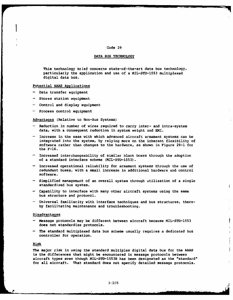
I
Code 29
DATA BUS TECHNOLOGY
This technology brief concerns state-of-the-art data bus technology,particularly the application and use of a MIL-STD-1553 multiplexeddigital data bus.
Potential AAAS Applications
- Data transfer equipment
- Stores station equipment
- Control and display equipment
- Process control equipment
Advantages (Relative to Non-Bus Systems)
- Reduction in number of wires required to carry inter- and intra-systemdata, with a consequent reduction in system weight and EMI.
- Increase in the ease with which advanced aircraft armament systems can beintegrated into the system, by relying more on the inherent flexibility ofsoftware rather than changes to the hardware, as shown in Figure 29-1 forthe F-16.
- Increased interchangeability of similar black boxes through the adoptionof a standard interface scheme (MIL-STD-1553).
- Increased operational reliability for armament systems through the use ofredundant buses, with a small increase in additional hardware and controlsoftware.
- Simplified management of an overall system through utilization of a singlestandardized bus system.
- Capability to interface with many other aircraft systems using the samebus structure and protocol.
- Universal familiarity with interface techniques and bus structures, there-by facilitating maintenance and troubleshooting.
Disadvantages
- Message protocols may be different between aircraft because MIL-STD-1553does not standardize protocols.
- The standard multiplexed data bus scheme usually requires a dedicated buscontroller for operation.
Risk
The major risk in using the standard multiplex digital data bus for the AAASis the differences that might be encountered in message protocols betweenaircraft types even though MIL-STD-1553B has been designated as the "standard"for all aircraft. That standard does not specify detailed message protocols.
3-105

Trends and State of the Art
- Bus Architecture. MIL-STD-1553B allows for dynamic bus control of the muxbus by other than the primary bus controller. The feature provides for buscontrol either in a command-response mode architecture or a polled contentionmode architecture. Work has been done by NADC relative to these two types ofarchitectures and it has been found that the latter type of mode architectureimproves bus transmission efficiency by eliminating static refresh cycles.
- Multiplexed Data Bus Cables. Several current users have implemented theMIL-STD-1553 data bus by means of RG-108 cable in accordance with the require-ments of MIL-C-17/45. Bus interconnections can be either direct coupled orstub coupled. Most users of the MIL-STD-1553 bus have chosen the transformerstub coupled architecture because of its flexibility in adding future systems.
- Transformers. Several manufacturers provide special miniature trans-formers for the mux bus as indicated in Table 29-1 with characteristics com-bined with those of the transceiver as shown in Table 29-4.
- Data Bus Receivers. The data bus receiver converts bipolar, biphase Man-chester II data to TTL levels in accordance with MIL-STD-1553 requirements.Manufacturers' part numbers are provided in Table 29-1 and typical character-istics are shown in Table 29-2.
- Data Bus Transmitters. The data bus transmitter processes TTL biphasedata from a Manchester II encoder for transmission on the mux bus in accord-ance with MIL-STD-1553 requirements. Manufacturers' part numbers are pro-vided in Table 29-1 and typical characteristics are shown in Table 29-3.
- Transceiver Module. Hybrid transceiver devices are currently availablefrom several sources, as shown in Table 29-1, that combine both multiplexeddigital data bus receiver and transmitter functions in a single package. Theyfeature low power dissipation and improved filtering on the receiver to enhancebit error rate of the system. Typical characteristics for these devices areprovided in Table 29-4.
- Manchester II Encoder/Decoder Module. Single hybrid converter modulepackages are available from several sources, that include the necessaryencoding/decoding, serial/parallel and parallel/serial conversion, addressdecoding and recognition plus tri-state double buffered output latches forthe data bus. Typical parameters for such a module are provided inTable 29-5.
- Serial Parallel Converters. This device, identified in Table 29-1,is a double buffered serial/parallel and parallel/serial converter thatprovides all of the necessary "handshaking" required between a Manchesterencoder/decoder and a subsystem microprocessor including the protocolhandling for both a MIL-STD-1553 bus controller and remote terminal.
- Remote Terminal Unit Module. Several manufacturers of hybrid circuitsoffer MIL-STD-1553B interface modules, as shown in Table 29-1, that performas complete remote terminal units (RTUs) by providing a transformer coupledinput/output, a transceiver, encoding/decoding circuitry, and serial/paralleland parallel/serial shift registers in a single package, as shown in Figure29-3. The devices can be employed as the mux bus interface for either afunctional remote subsystem or master bus controllers. A functional blockdiagram for an RTU is also shown in Figure 29-2.
3-106

I1
Cost Direction
AAAS life-cycle cost reductions may be realized through the incorporation ofa multiplexed digital data bus because of its inherent flexibility for systemreconfiguration and troubleshooting. Direct cost comparisons with currenthardwired systems are difficult to make because of the limited use of MIL-STD-1553 data buses in stores management systems of active aircraft.
3-107

44
- Q)
-l
III
C U14
LU)
L0 0
100
3-10
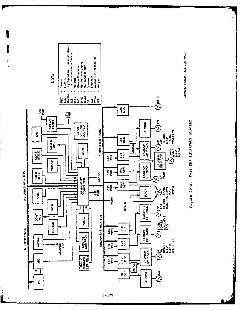
Il1.U
z 20C 7 5
.w 2 72 ~ca i
0 )rn Vcc >LU U L
.j zLU
IL
00 L
A,- " .
0 5 W -'C
LL2
0 C
U lU .....
02 uj w
4 m -0 (A~ LZU Wi
-U
< CL(n 3-a109w

Q
E-4
z
-1-
UU
a 0-~ -4
m ww m L~L
Try 'ILng
LLA
E-4A
ML
3-110

I
Table 29-1. MIL-STD-1553 DATA BUS COMPONENTS
Manufacturers' Part Number
Device ILC/DDC CTI Harris SMC
1. Transformer BUS-25679 CT1231
2. Data Bus Receiver BUS-8555 CT3078
3. Data Bus Transmitter BLU.-8556 CT2077
4. Transceiver* BUS-8553 CT3231BUS-8554**
5. Manchester II BUS-8937 CT1555 HD-15530Encoder/Decoder HD-15531
6. Serial to Parallel COM-1553A***Converter
7. Remote Terminal BUS-1553 CT1553-1Unit
*For MIL-STD-1553B applications**F3 replacement of CT3231; operates from ±12 to ±15 Vdc power***Operates with HD-15530 or HD-15531 modules
(ILC/DDC = ILC Data Device Corp., Bohemia, NY; CTI = Circuit Technology,Inc., Farmingdale, NY; Harris = Harris Semiconductor Products Div.,Melbourne, FL; SMC = Standard Microsystems Corp., Hauppauge, NY)
3-111

Table 29-2. DATA BUS RECEIVER PARAMETERS
SPECIFICATIONS FOR BUS-8555
PARAMETER UNITS VALUE
ANALOG INPUTSBipolar 1Differential) DATA and DATA V 40, p-p (max)Input Impedance (Differential) 11 4 k (min)
Common Mode Rejection Ratio dB 40 (min)Threshold Levels
internal (preset) mV 750. p-p (nom, with pins 18 & 20 grounded)External Threshold Adjstment V 0.0 to 2.0 (adjustable linearly with G.On to 10.0 kit resistor
respectively to ground.)
OUTPUTSDATA and DATA Output TTL Level Manchester 11 (biphase) serial data
POWER SUPPLY CHARACTERISTICS RANGE CURRENTOperating Voltage Range ~4.5 V to 5.5 V 20mA@- 5V
10 Vto -18 V 15 mA@ -15 V.lOVtO.18V [email protected]
THERMAL CHARACTERISTICSTemperature RangeOperating
0 C -55 to + 125 (Case)Storage Temperature Range
0 C -55 to'+ 135
PHYSICAL CHARACTERISTICSSize in. .895 X .950 X 0 15 max (22.7 X 24,1 X 3.8 him max)
Weight oz 0.3 (8.5g)
Table 29-3. DATA BUS TRANSMITTER Table 29-4. TRANSFORMER AND TRANS-PARAMETERS CEIVER PARAMETERS
SPECIFICATIONS FOR BUS-8556PARAETE UNI VAUESSPECIFICATIONS- TRANSFORMER AND BUS-8553 HYBRID
PARAMETER VALUE
DATA auto DATA TTL (Drivng logic must sink RECEIVER'O.7mA mal Inu Leveil 40V 0.0 d,f feyefli me.
Inhibit TTL to inhtibit transmitter (Dml- Incur Imtpedance 4 KfI differential inig logic must sink 0.36 Thretod Level IV P-g ntominai. internaliiy st (direct
MA mx Icoupled mode)i
OUTPUT~ ~ ~ ~~ ~m CHRCEISISaIR 0d mnu i ~DATA en DNATAcrnla (P-0 Outpu mnve TTL 2iZdTAeetal DATA4 p-we O upo Lave tir t TT5L±5)030m adoutputtIedanc 2. <10 Powe Suppn traunsmietitg -V lS%l @0 mA max
Harmonic Cott Fitered to eliminate itvittofica ____________
above I1MHz lset figuire 3) TRANSMITTERDitterit salGroup Delay ns 3 input Level TTLoutput Nont. my 100 0 Output Level 27V p-p nominal crosa 145nl load
POWER MEoUINIMom1 20V pvg nominlal (measured at Point C.Po~gvilguilaui V 5t5%J!12 to-IS Figure 2)
Current isee Figure 4) mA 12max 120 mat RisedFebl Time 130 ngesc typical40 muattf Output Noise, 10 mV p-o ditferentitl max
Powe Diae.pation -att 21(100% duty cyclel Output Impedance (Receiver 4 KI2 differentil mitt let I MHz)
t Treanamtiing Mode)tt Stnb Poweir Supply Requirement$ -15VI!5%l*?0 mA max @25% Duly Cycle
(9 2S% Duty cycle-Transmit 150 mA -ma @ 00% Duty CycleThERMAL CHAPACYNfge11a Model +SV It10% S mA max
Operating :c 55 to.125Storag C -55 to-ISO GENERAL
Operating Temperature Range -55*C to -125*C Icaae, temP.IaMYGM Q*AiC1S7CSStorage Temperature Range -55'Ct 10 .35*C
Size 'n 125. tI25 x 0.20 (32 Sit 324 pix~~yrd 1.4 tO0.8 0+. nc
Wiegi oz To be determined Weight .A or. (typl
NOTE: P/N BUS-8557 available for ±12V operation; consult factory,
-All tables courtesy IL C Data Device Corp.
3-112

Table 29-5. ENCODER/DECODER MODULE PARAMETERS
SEECIFICATIODWS JcQ WO15531
ELECTRICAL CHARACTERISTICS VCC - 5.OV 4-5% TA - Industrial or Military
SYMUOL PARAMETER [MINIMUM [TYPICAL MAXIMUM) UNITS[ TEST CONDITIONS
VIM Logical "I Input Voltage 70% VCC 1 VVIL Logical -0- Input Voltage 20% VCC
VIMC Logical "I "Input Voltage (Clockl VCC -0.5 VVILC Logical 0" input Voltage ICOk GO -05 vIlL Input Leakage -1.0 .1.0 uA O C VINy 4CV
yaM Logical "I" Output Voltage 2.4 V IOH - -3mtA
D.C. VOL Logical "0' OutputI Voltage 0.4 V IOL - 1 linA'CCSS Supply Current Standby 0.5 2.0 mA VIN - VCC - 5.25V
output$ openICCOP Supplyv Currant Operating' 8.0 10.0 mA VCC - 5.25V,
CIN Input Capacitance* 5.0 7.0 pF 1S z
co Output Capecitance' 8.0 10.0 pF'Guaranteed and Sampled but not 100% tested.
ENCODER TIMING - - -____
PC Encoder Clock Frequency 1 5 M __zCL __50_F
FESC Send Clock Frequency 2.5 MM:TECR Encoder Clock Rise Time 8 nTECF Encoder Clock Fall Time a nsrED Oata Rate I 1.25 MHzTMR Mastor Reset Pulse Width 150 n lTEI Shift Clock Delay 125 n:s
A.C. TE2 Seral Data Setup 76 nsTE3 Serial Data Mold 75 ns
TES Enable Fulse Width goTE6 Sync Setup 55TE7 Sync Pulse Width 150 itsTES Send Data Delay 5Te9 I Bipolar Output Delay30 J s f J
DECOER TIMING
FOC Decoder Clock Freqtuency 15s - MHZ CL 5OoFFos Decoder Synchronous Clock 2.5 1 MHz
TDCR Decoder Clock Rise Time a nsTDCF Decoder Clock Fall Time 8 ts,DD Data Rate t.25 MHzToR Decoder Reset Pulse Width 150 n1
TORS Decoder Reset Setup Time 75 nsTMR Master Reset Pulse Width 150 nsTDt Btooler Data Pulse Width TOC .10 nsITD2 Sync Transition Span 18TDC itsI
A.C. TD3 One Zero Overlap TDC -10 n,TD4 Short Data Transition Span 6TOC nts1
T5 Long Data Transition Span 12TDC nsT06 Sync Delay (ON) 110 ntsTD7 Take Data Delay (ON) 110 nTD8 Serwa Data Out Delay 80 itTog Sync Delay (OFF) 110 ns
T010 Take Data Delay (OFF? 10 itsTotl1 Valid Word Delay 10 n:TO t2 SynchronousClock To Shill Clock Delay ,75 nsTD 13 Synchronous Data Setup 30 itsI
NOTE (D 15TDC .10 * 15 1Decoder Clock Period)l 1 1Ons ToC .Decoder Clock Period.1These Parameters are guaranteed but not 100%h xested. FOC
-Courtesy Harris Corp.
3-113

4'- 0 3 0 (
u CL 0I 0~- 4) F )
Q. Al 4 .6 )1 cr u
Co Z) ) >0 Q m~ 1)
0 n
L.*O .- ) E0O -r
rn -
V)*~~2 I 0
.0 ~flE- U XX x x
La 0-
--0 ' w --IUud I II I
e eu
>><- (n
> a
I- - +1 L .4C.)~U. +I I
C1 CNJ a,
_-4I
E-4 -j .. C U
o ~ z~C 04 LU cO
ZC 00
S .. - 02
cc 0.na CL 0
3-114

I>0'4
00
4, 0
r, 4,4, 0
o .4 0
u rO -i 4, 0 U
4, 041 - 04 1
0 0 0 ' ==4
,0. 0 0- ~~ ~ t 4U n4
00U ,4 . UU4
= 4D4 414
4,4 4 0 U 4 4 - 0 4,f 0 J4, U 4 4 £ 00
0 u 0
4,
0 0
41 3U~ 4.4,4
0O 0 u ~ ' 4 ,.
0 -o 4, 0 ,4, . U4 8, , 0 1. ~U 4, u0 U , -. 4 , 4
F. -a - 041 ' 4 . 0 4c , c,4 4, U
W 4u *2 .13 Ur U1,. , 4 04 40 4UA m Ea A.1 c0 "C' c. -C X - 0. 0
U~~c,-.4 0 4 . 4 C . .'C 4,n 0' E, 4,
US 4.. I C0' I 0 .4~ . I I -3 I -1154

C -
.3 0
oc aa 0,
3. 00
C~ 0 3
a, C n
El 3 0 4 'cm .0 -MA
43 43 0 C0a,~ ~ 0 -- C 3 C - C
4 . - C= a,~
4, U Ua aC CC
t URU 0 Cn 1
>. U 3- 0 3 33 U116

00-UU
- PC.UU
fn 0
0 0
0. u
1C -It 0
C 2 U30117

Code 30
ELECTRICAL TECHNOLOGY
This technology brief provides information on hybrid microcircuits,including A/D and D/A converters, operational amplifiers, solid-state power supplies, and regulators; as well as on connectors.Whereas Code 34, LSI Technology, describes monolithic circuits at ageneral level, this brief discusses the state of the art for spe-cific devices and circuits.
Potential AAAS Applications
- Power conditioning equipment for conversion and interfacing with aircraftpower systems
- Stores station interfaces
- SMS intercornections
Advantages
- Hybrid devices provide higher reliability, greater density, lower cost,and smaller size and weight than the discrete counterparts. Furtherdetails are provided in Table 30-1.
- Hybrid circuits can withstand extreme combinations of electrical, mechan-ical, thermal, and environmental stresses such as are expected to be encoun-tered by the AAAS.
Disadvantages
- Lack of device standardization due to relatively new types on themarketplace.
Risk
Premised on the fact that hybrid microcircuits are successfully implementedin airborne military programs, the risk in using these devices (when Mil-qualified) for the AAAS is considered low.
Trends and State of the Art
- Power Conditioners. Hybrid microcircuits are experiencing greater use inpower conditioning applications for advanced aircraft armament systems. Typi-cal state-of-the-art devices include hybrid linear series regulators havingoutput voltages ranging from +5V at 3.5A to +36V at 20A. Complementary nega-tive voltage regulators have outputs ranging from -5V at 2A to -12V at 8A.These regulators are available in single or dual form, or as multiple typescontained in the same package, with overvoltage and overcurrent protectionincorporated into their design.
- Switching Power Supplies. These devices operate from l15V, 3-phase,400-Hz prime power sources to provide ranges of characteristics from +5.3V at114A to +15V at 0.2A. Negative voltage systems are available to complementthese components.
3-119

- SEM Devices. The Standard Electronic Module (SEM) devices are availablefor advanced armament systems. SEM devices are discussed under Code 37, Pack-aging Technology.
- Relay Devices. Numerous types of high-power, solid-state relay devices(e.g., 75A steady and 1000A for one-cycle surges) incorporate transistorsand/or silicon controlled rectifiers. The trend in this area is towardincreased current and voltage capability. New materials and manufacturingtechniques are supporting these developments, with high-reliability productsresulting for applications of armament systems.
- Converters. D/A and A/D converters are available as hybrid circuits, andare beginning to emerge as monolithic types. Hybrids still provide the bestperformance, however, and a large number of hybrid types are fully qualifiedto MIL-STD-883, Method 5008. Available are high-speed D/A converters (25 and50 ns maximum settling times) having capacities of 8, 10, 12 and 16 bits, andhigh-speed A/D converters (600 ns maximum conversion time) of 12-bit capacity.
- Operational Amplifiers. In addition to converters, operational amplifiershaving very high slew rates (e.g., 1,000 V/us) are available in productionquantities.
- Conrictors. Major advances in connector state of the art are of interestto tne stores station interfaces and internal electronics of the AAAS. Sev-eral mc. facturers are producing Mil-qualified connectors having improvedRFI/EMI shielding characteristics (see Code 31) and better moisture-sealingcapabilities than previously available (see Code 4).
Connectors of the above type are designed to permit replacemrnt of individualwires, or to accept wires of varying sizes, with no penalty in reliability.Individual wire sealing is by gaskets or grommets and crimping procedures.Plastic inserts provide structural as well as dielectric benefits for Milconnectors. Contacts are gold-plated copper alloys, but the high cost ofgold has resulted in numerous R&D efforts to reduce or replace the goldplating.
Connectors are available that can acco.-mnodate up to 104 contacts per insert.Subminiature types handle as many as 85 No. 22 contacts in a size-18 shell.
A series of connectors is now available for high-reliability military avi-onics applications. These connectors incorporate quick-coupling threads andan antidecoupling device to prevent vibration problems.
Connectors for use with flat cables are state of the art tor stores manage-ment aystems that do not require rigid environmental protection, such asneeded for SS1 connectors. These flat-cable devices are available for connect-ing up to 50 strands of wire. A recent development in flat-cable interconnec-tions is a high-density connector for SMS applications that accommodates two40-conductor flat cables, resulting in significant weight and volume reduction.
Cost Direction
The life-cycle cost of hybrid power circuitry is projected to be less thanthat of discrete-device power circuits since hybrids operate at a lower tem-perature and have a higher reliability. Costs of Mil-connectors are going upbecause of the increase in the price of fabrication materials (gold plating
3-120

I and other precious metals). However, large quantity procurements and elimina-tion of failure and corrosion problems should produce lower life-cycle costsfor the systems in which these connectors are implemented.
The cost direction for switching power supplies is illustrated inFigure 30-1. It can be seen that the cost of switching supplies is decreas-ing and becomes almost equal to that of linear supplies during the 1980 timeperiod. Linear supplies were lower in cost up to that time.
3-121

.14 dP
dU CO
-4 -4 L
E-1 .1 L
00
IU z0 'J
H E-4
C-n
0
41
$4 o *
00
-f ko 0(M) jaOd Ind~flO 0 0 *
x
1-4'40
-4
-4 zU 4 i2
3-122

10 10
0 0. 4'0 0 0
.0 0.
U 0r 0 1 or .
0 '
10 0 0 u 0 wUO c u -C C
0 0 0 c 0
; 0 u 0. U
0 4' t* IV-0 a,
.0 u xeN' 0 0
0 C. 0r 4. .
-u u.0 4' > 0 M
0 0 2 0 , 0' a
-0 0.4 In 0 'au - M - Q M - 4 00 0
-C In uh I- -* 0 4 a J)
o U 0. 0 a' 0 000 N
U 4' - U00 0 4'n
-. '0 0 1 ~ 0 4'. 00.~h 00 00 . 0 ha .0 4
~4' 0 ~0* 0 lb
00 8; ~ .01 U h
h.'~ - ~ a - . . - -
0 4'. 0~ ~ .U U 0 :1 . Z 0 ~ '
4' 0 . . 48 0 &. 0 0 . U4' 0 .0 . 4 4 - . 4' r. 4 0 4 . 4 0
o i ~ 0 0 U 1 g ' 0 0 C m - ' 0
4' . A u.c0
a: 0
14'
I W.-4
W V0 n , :
0- 0 0
.~~ i3' 123
0I
a V
C
WO 0
-V0tLa ha
41 0 .
0 -U
cC - C 1000w 0. Z
cam C 0 0
00 1 V-c 0 0
4 01
to 0 o 00a C C L
OW C OC , .. --. N
O 0 LI0
a,
V
0' L
- n 0 Vtu P
70 ' o.0 . h
0 -C 0 t0 all M - C 0 -00 0
C 04 11C
0 0 41 0
4> 0 0
->OC -, e S r
01 0 0u
Il 0 LI no
3-10
~00
r -
0
a c .
-C -C
3012
Code 31
ELECTROMAGNETIC ENVIRONMENT TECHNOLOGY
This brief addresses electromagnetic technology relative to itsapplication to the AAAS. The information provided concerns electro-magnetic compatibility (EMC), electromagnetic interference (EMI),and electromagnetic pulse (EMP) characteristics and components assoc-iated with advanced aircraft systems.
Potential AAAS Applications
- All AAAS subsystems employing electronic and/or electrical circuits.
Advantages
Judiciously applied electromagnetic technology yields:
- Decreased susceptibility of sensitive digital devices and circuits to theeffects of conducted and/or radiated EMI through proper shielding, ground-ing, bonding, and filtering technologies.
- Increased reliability of weapon separation and control guidance throughthe specification of appropriate EMC requirements and tests of MIL-E-6051and MIL-STD-461.
- Enhanced system protection from conducted transients associated with cur-rently used discrete/relay technology, through the application of fiberoptics and multiplexed digital data bus technologies.
- Increased system protection from circuit transients when conventional high-current relays, solenoids, contactors, etc., are replaced with the solid-state power control devices associated with an EMUX system.
- Ready avaiiability of mathematical models to help analyze and resolve prob-lems of inter- and intra-system compatibility.
- Increased nuclear hardening through application of proven design tech-niques and components that can withstand the effects of EMP.
Disadvantages
- Increased system cost and weight due to tendency to overspecify EMC andEMP requirements.
- Reduced technical innovation and/or use of state-of-the-art componentsbecause of requirements to meet specified levels of nuclear hardness (seeTables 31-1 and 31-2).
Risk
The primary risk in applying electromagnetics technology to the AAAS involvespossible cost and schedule impacts to the development and testing of the hard-ware, particularly in the area of nuclear hardness. A tradeoff between sys-tem safety/survivability and cost has to be made to determine the level ofnuclear hardness desired. Very little risk is involved in applying sound EMCrequirements appropriately.
3-127

Trends and State of the Art
- Connectors. The latest series (III) OF MIL-C-38999 connectorsincorporates expanded EMI shielding protection compared to earlier series. Aminimum shielding capability of -65 dB at 10 GHz is possible with the newmetal-to-metal coupling finger design.
A new development for advanced armament systems is the Radio Frequency Atten-uating Connector (RFAC) used to connect electrically initiated explosivedevices to fire control systems. This connector provides RF and electro-static hazards (RADHAZ) protection. The RFAC operates on an inductive coup-ling principle. In addition, several RFAC versions using fiber optics tech-nology have emerged for armament systems.
- Fiber Optics. Many advances have been made recently in fiber optics appli-cations in aircraft. The technology brief for Code 32 presents more informa-tion on this subject.
- Solid State Power Controllers. Recent developments in the area of solidstate power controllers for controlling aircraft power (and thus reducing EMIproblems) have resulted in the development of a specification, MIL-P-81653,for potential advanced armament systems.
- Filters. Signal line filters are available that can be incorporated intoconnector pins, as illustrated in Figure 31-1. Most connector manufacturerscan supply this type of pin filter. Ferrite beads are also available forin-circuit filtering of critical signal lines.
- Shielding. As wire shielding technology advances, additional standardshielded cables are added to the military system through MIL-C-17. An exampleis the RG-108 cable, used for MIL-STD-1553 data bus interfaces. Figure 31-2shows an acceptable method of terminating such shielded cable. Table 31-3lists techniques for shielding against the effects of EMP.
- Radiation Hardening. More types and quantities of radiation-resistantsemiconductor devices are becoming available (see Table 31-1). A major trendin semiconductor design is the use of dielectric isolation to obtain radia-tion hardening.
Cost
Overall system life cycle cost should be reduced through the judicious appli-cation of electromagnetics technology to the AAAS. Cost savings should beachieved through increased system safety, enhanced mission survivability, andreduced system downtime due to intermittent EMI problems.
3-128

E-4,
z 00
LU C~L U
(L 0
0 - E-4 LH
zd z
T. xl- H 00-LC z z UJz, H
-O Occ r4 o 0CL0 y. C
I- 0
U, Ct
4U CC
UD zc . . c -2
3-129

z -nC>
E. 20
ZCJ2 u a z - a
E -
DL 1O) OS 4
-i E-4 z to
'3 0 EE
0 0 0 0 0 1
-4-
S 5
U) E. E
o/ E-' 0 A 0
w; u
0
0 m w
U W
-I £
0 E-
U)E-4E-4 z IIIC
CA IfA
E-4.
3-130 -
4,, CL
U, a 00 Wo 'A
-C - 0z> 0 4
o c
-C C u
0. 0 0 4
ca 0 1 0 0
1) 4u" 4,C4, U. .0 0
0 0 0 4,
u -IC 4, WO-4,m d 0 -C 0
u 0~X 4, A , 04~U-
oz 60, 0 , 'U . .
*~1 1- u. .0 U ' , N
-0 T , . ;. - 00 U 4 - 4
u a4 c u -0
0Q .. 0 . , - S. 0 o' 0 40 " 0 dC A34' . ~ ~ ~ ,
C , *. 57 4, * 4
4, 0 i. -C 00 0O U f. 4, 0U ,
4, .0 4, . , - .0 , , - .0 , 34,-1314
0
0 C00 20
00
4. > 30~ 0 .
4 u
>0 0
-0 0 u44
0> t- g 0 .04 .4-C ' - C 0 4 .C -C 0 0a m
2 0.CC
a~l UCI C
0~1 1~COC > C S
0-~1 x2~0~.'4 41
of. .U O- U 0*0 ~ >Ce 00 -~I C
0'Z~~ ~ 8 1 C.3 ~~
- 1 -- 440 mo 4Z I
4 - 4 3-132

CC a
0'0
*00
LO -4
'n 'a C
0 0)* 04,
's t, 'm .C0
a u I- -
3-13

I
Code 32
FIBER OPTICS TECHNOLOGY
This technology brief focuses on fiber optics cables, light sources,detectors, connectors, and transmitter/receiver modules.
Potential AAAS Applications
- Standard stores interface
- Data transfer equipment
Advantages- Wide bandwidths (100 MHz or more) and high data rate capacity (300 Mb/s
presertly, with up to 1 Gb/s projected).
- Elimination of electromagnetic compatibility problems in armament systems.
- Immunity to electromagnetic pulse effects, thus providing a radiation-hardened environment for nuclear stores.
- Absence of radiated fields, for greater communication security.
- Elimination of ground loops and the need for shielding.
- Absence of such hazards as sparking, fire, and explosion normally asso-ciated with conventional electrical systems.
- Significant weight reduction through use of a lighter (nonmetallic) con-ductor medium instead of copper wiring, and the elimination of shielding.
- Direct usability with optical sensors without the need for amplifyingcircuitry.
Disadvantages
- No fiber optics components are military-qualified. However, investiga-tions and tests show that for an advanced armament application of a MIL-STD-1553B 1-Mb/s data bus, a compatible set of components exists that canbe qualified to MIL-E-5400.
- Signal losses due to fiber attenuation and mechanical mismatching of fibercables to connectors can create problems if not properly controlled. How-ever, recent advances in technology have significantly reduced - and insome instances eliminated - mechanical mismatching.
- The fiber optics industry is geared toward mass production of componentsfor telecommunication systems, and has not begun to pursue the potentiallylarge volume of military applications, such as that of the AAAS Program.This situation has led to nonstandardization of components.
Risk
The risk in applying fiber optics technology to aircraft armament programs isconsidered low-to-medium because of the many successful applications reported.For example, in the ALOFT program for A-7 aircraft, development of
3-135

a fiber optics interconnection system for a data bus application was con-sidered of low risk.
Trends and State of the Art
- Fiber Optics Cables. The number of suppliers of fiber optics cables suit-able for use in military SMS applications is increasing. New materials havelow attenuation losses (see Table 32-1), and are available for single-modeand multimode propagation. Losses as low as 1 to 3 dB/km are reported forsingle-mode fiber optics, making them suitable for use as a data bus (MIL-STD-1553B) for advanced armament systems.
- Light Sources. Light sources consist of GaAs or GaAlAs, and emit infraredwavelengths of from 750 to 950 micrometers. Technology advances are increas-ing the spectral range from 1.0 to 1.6 micrometers to overcome attenuationlosses (see Table 32-2). The number of suppliers of these light sources issteadily increasing. Problems of coupling losses and lack of external opti-cal enhancement are being eliminated, in the former case through hermeticsealing of emitters.
- Detectors. Detectors consist mainly of PN, PIN, and avalanche photodiodestructures. Significant advances are occurring in the detector field to over-come problems of losses, with one approach being the development of integratedamplifiers on the same chip as the diode (see Table 32-3).
- Optical Connectors. Connectors for fiber cables are now available thatoptimize transmitter and receiver alignment (see Table 32-4). Another majorconnection available for fiber optics is patterned after the Standard MilitaryApproved (SMA) RF coaxial connector. Of further interest is a hybrid connec-tor that accommodates a mixture of electrical and optical signals. Connec-tors are also being developed containing combined light-emitting sources anddetectors.
- Transmitter and Receiver Modules. Several companies have successfullydeveloped fiber optics transmitter/receiver modules for advanced armamentMIL-STD-1553B applications. Table 32-5 provides further details.
Cost Direction
For at least one application, the A-7 aircraft, fiber optics provide a signif-icant reduction in total life cycle cost relative to the use of wire alterna-tives. The economic advantages are due to the lower cost of fiber opticsconnectors, cables, and circuitry versus the cost of conventional elements(see Figures 32-1 through 32-5). Other data are given in Table 32-6.
3-136
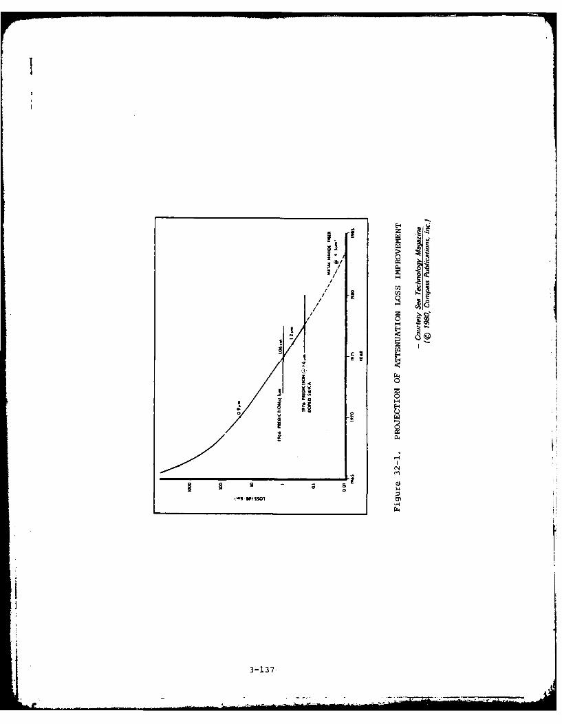
1
~C~
/ H e/
//
/ S// S
// z ~
/ C ~H
'~ -
z-4
rz4CI
CZr H
0 - 0 C.)a -
V-4
CN
S9 - 0
1101 0'-4
3-137
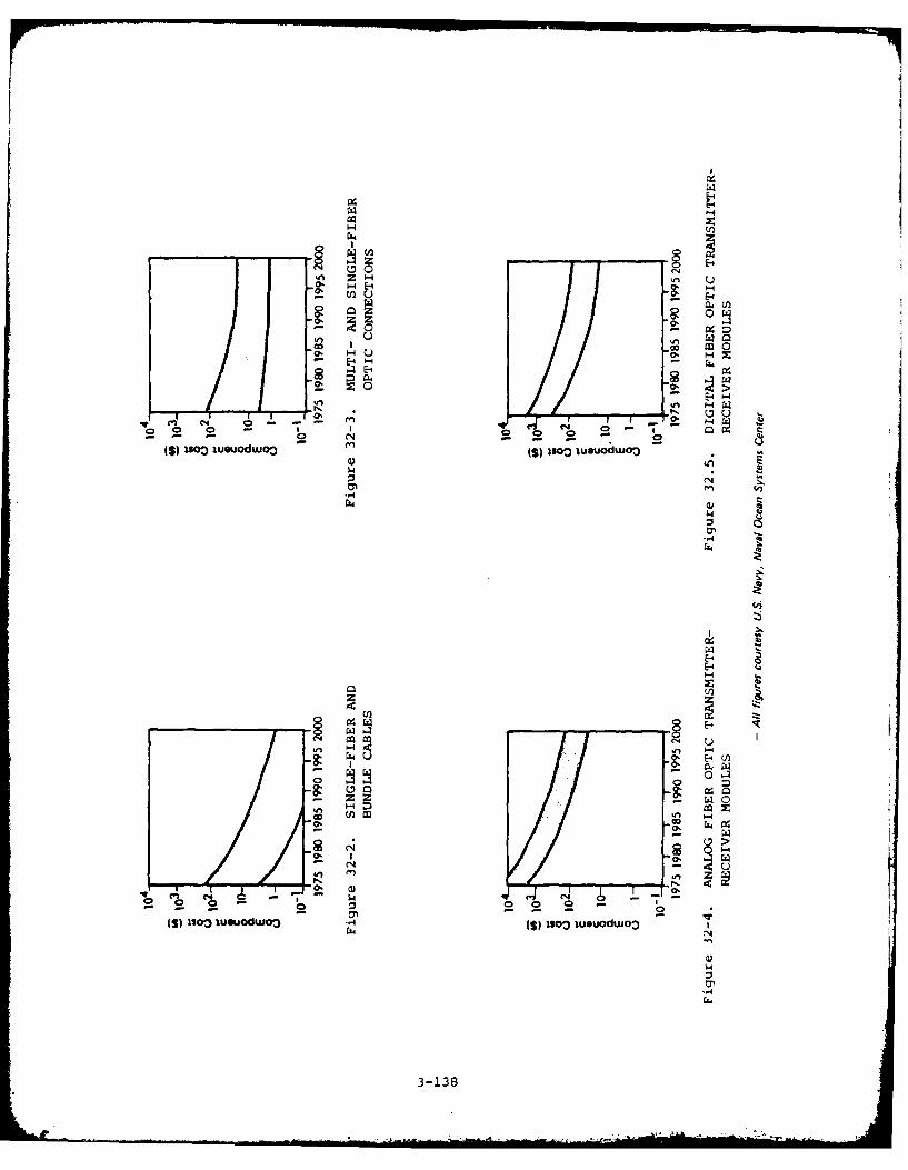
(4U H E- u
HE-f
WI) U w, ~00 HU 0~
U, - -
u U,
0.o *Nuowo (s) IQolooL
00
L-4
W, H
00 -§
co n 0o
- 4 >
o4 Cz 4
(S) ~ ~ ~ ~ 0 123II~W3- I)io uudo- (
U' "' 1~3Z138

Z,- - -6 I~~ 1 )
E: A __ E- 0 m .E0
EEE OE0 , C E E xm v e. M - 04l U LOf -'' N
4z v -it en 00k na4N -1 k ot
-4V -- "4 NNN MJ M) CI C-4- CN CNNC -- - NM Nc oo 00 00 0 0 60 06oooeol 6
ANP N m =
u C~d N (1 \ N(1 CA-
000 co 00E 000 NO 00U Go)W @'co ~ ON0 §0 cc C~ 0 No C@
@10 00 N co o o @ ~-4Ln~ 0 n.o. ifl4. ULfl '-'' M in O UU)-
II -O
Sh- 1 " 0 1G
C*- LON Ln l NNj InNC~~0 so 'O8e' 88~ M, m' N'g' htNU) NO O
n N - n c o%fn ft ' ~ ~.
10
-- -.) Ln
C nO a a 9L mCL (
NC)
3-139

Cu 0 Ln LA 0--- VI VI VI 1?v 0 ' X - - -
LA. L
I U) LA co 0 a0-ma 04 Ul0C
LL v
E-4
E-E-4 0
E LA
Cl,0 m0 z
u E, 04 0 L
0>4 cC
FO A 0
C C C Co m C
0 .2 V
0. 0 0 0 0 O' >0
m. 00 =a t 0 =EE 0
0 o 0 01
w 66
3-140

E-.
0
o 0 ~C
H - CU <-CC
o- u EE E :c
-m 0 CU'n v ~ + C.-
C.) 2-o co 'dqH 0 C OCo 0 n >E-4 ~ Z z cW z "W Z N qn -+I
u uuC0
0
>~ C
u cc
E-4 ~ c C
V's - I m u a.-
(n :3 CD~ cc aL E c
cc E~~ 0, w E a: TO* cb I- 2b- 3(DE , (p -
c
-22 Ez *IU..
0~ 31s a
CL E.
H HE-4 4II 0 .
M cm -W
caS Co nN 8
N.. ~- in
AvC
-a
-3-141

.40 2 E
~~0 cE c 'a cc
we c I. Q 0 - ~ ~ il
.0E ECU. E ~
I __ X_ CL__ U __M __ wCL 41 u C-a L, j0
RIF a
E E
a--
_ _ __ _ _4 N~ C4 ~ v U Ule)(J CL CL
E E,

CO
o A,
0 0
o al
I z- VCo "Ct0
0'4 0C I QIc0-C 0
ma a 41
c ac
0 1aO
u a u NU
ol Cu ME~.a aaa C * *C di 0
-C -0 N*
C - 0 'a N C .
a, . . n , a * a 0 M
~ 0 0% - a Z~ 0% ,-co a - C C
-a - 0 - -a % - - a
a aoa u 10a a - a ala 0S. b~f U -
-- ~ tn v a Z I ar
c-a 3-43 a %

Q, 0
I U
c C0 0o1 0
0 01 0 01
31 c 00. u, 1 0.
C~~ - 0 00~~ 0 00
a 2 0 CC 0 2
u 0 0 u
00
x 0 A
a, 0 .0
-g c 002 8 . 2 0 o
o 10
z mJ 0 .0 0 - W
. m CU~ 0 -U4 am w U)0 "
2 U all, 00
00 4) T- 0 0
t 00 E. Z, 40
00:f - 0
3-144U

0.0. C ,. 2
tr 4*
0. I- -ca 022 0
0 00U- 0 0-C 0 .
r,4 040 O, U
0
U~, C ,4. 4,0 .4
0 0. 04, 0 ,
0~~~r -,10-a-
4, 4,40, U ,au a, -N
.0~~ . aw0- ~* 1CU4' OU
0~O 0 01 0
It 0'.44 4.
.0 I- -c . 041. Ic a.
0 I. 0. t-3. -14500 0

I
C0~
V- So a
C
aV -
V V -I, S I- C) NC a -- Ii, b. -
- I IC N a
I' A A I3 -
V 0' 0- C - = -P 0. 4' N
a - N
4' Ii -o 6 e C C -
V - C Na C Z- N -
C'a ~a e
*4D * 0'a . C -c a a A..*01 ~S- 5 -~ N
C ~ 0 5V~ - C a w .. a -- A
- N 0 0~ g *a -4N. ~ - ~ a-
3~146
It

I
Code 33
COMPUTER PROGRAMMING LANGUAGE TECHNOLOGY
This technology brief addresses representative programminglanguages widely used in military systems having applicabilityto the AAAS.
Potential AAAS Applications
- Stores management software (operational and executive)
- Stores system management and control
- Weapon delivery control
- Signal processing
Advantages
- Pascal, FORTRAN 77, JOVIAL, Ada, and CMS-2 all provide for structuredprogramming.
- Pascal permits a smooth transition to Ada.
- JOVIAL and Ada, as compared to CMS-2M and FORTRAN 77, are projected tooffer better reliability and maintainability.
- CMS-2M can specify packed tables for interfacing with hardware-defineddata structures.
- CMS-2 is widely used for Navy computers.
- Ada permits multidimensional structuring of programs to meet the parallelprocessing domain of embedded computers. Ada also allows for plug-in useof software components, regardless of the source language in which theyare written.
Further advantages are listed in Table 33-1.
Disadvantages
- HOL execution time is slow, but this disadvantage is negated by the use offaster microprocessors.
- HOL programs generally use more memory.
Further disadvantages are listed in Table 33-1.
Risks
The primary risks of slower processing speeds and inefficient use of memoryassociated with HOLb in the past are disappearing. Current versions of theHOLs discussed above will satisfy most requirements for AAAS applications.Ada represents the highest risk of the HOLs discussed here, since it is a newlanguage and therefore not proven. However, its design has been an ongoinginternational effort since 1975, and further is fashioned very closely tothat of the widely implemented Pascal. The primary risk associated with Adais the shortage of personnel experienced in its use. Systems currently indevelopment or about to begin development can avoid this risk by utilizing
3-147

other HOLs, such as Pascal or J73, for initial development and implementation.After successful implementation at some future time, the operational softwarecould be transitioned to Ada, the planned DoD standard HOL.
Trends and State of the Art
SMS software is being implemented to an increasing extent in HOL rather thanassembly language. Assembly language will still be used for some time forsituations where timing and/or memory space are critical. To accommodate thetrend toward HOL, a great quantity of HOL software development tools are avail-able, including program design language, debugging aids, and system hardwareand environment simulators.
Extensions of Pascal, such as Concurrent Pascal and UCSD Pascal, go far inmeeting specific programming requirements. Another example of an extendedPascal is OMSI Pascal, which can be implemented for real-time applications.
In 1976, a 10-year program was adopted for the JOVIAL language by the AirForce Systems Command. The purpose of this program is to reduce the currentinventory of "JOVIAL-like" languages to two standard versions (J3 and J73),with the intent of reducing the number of JOVIAL compilers that must be main-tained and simplifying training requirements for Air Force computerprogrammers.
Firmware is being developed by private industry targeted to specific HOLs,such as Ada and Pascal. This would enable software development directly onthe target computer rather than on a software development computer that merelyemulates the target computer. Such an advancement would decrease softwaredevelopment costs while increasing efficiency.
Costs
The increased use of HOL and off-the-shelf software not only reduces develop-ment costs because of higher programmer productivity, but also improves sys-tem reliability/maintainability and thus decreases software maintenance costs.Software design aids are gaining in practicality and usefulness. These aidin quality control of software, which in the future may account for up to 50percent of the total development budget. This expenditure is justifiablebecause of the potentially great cost of removing a "bug" in the field.
3-148
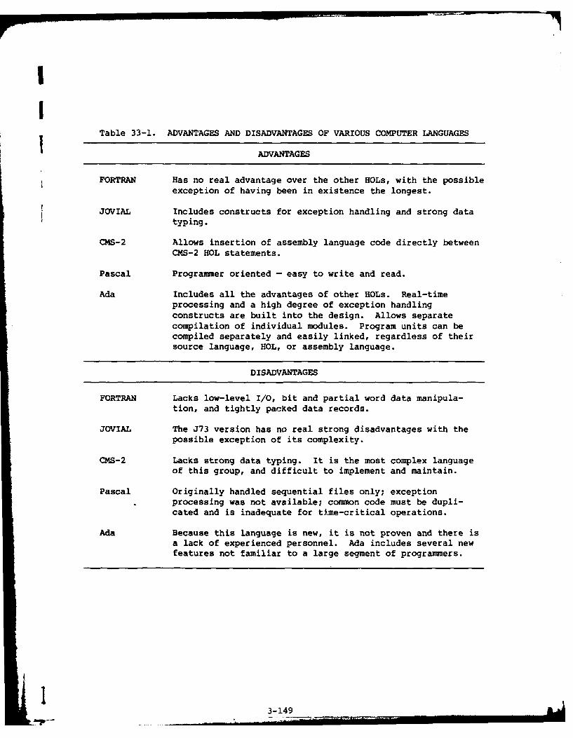
Table 33-1. ADVANTAGES AND DISADVANTAGES OF VARIOUS COMPUTER LANGUAGES
ADVANTAGES
FORTRAN Has no real advantage over the other HOLs, with the possibleexception of having been in existence the longest.
JOVIAL Includes constructs for exception handling and strong datatyping.
CMS-2 Allows insertion of assembly language code directly between
CMS-2 HOL statements.
Pascal Programmer oriented - easy to write and read.
Ada Includes all the advantages of other HOLs. Real-timeprocessing and a high degree of exception handlingconstructs are built into the design. Allows separatecompilation of individual modules. Program units can becompiled separately and easily linked, regardless of theirsource language, HOL, or assembly language.
DISADVANTAGES
FORTRAN Lacks low-level I/O, bit and partial word data manipula-tion, and tightly packed data records.
JOVIAL The J73 version has no real strong disadvantages with thepossible exception of its complexity.
CMS-2 Lacks strong data typing. It is the most complex languageof this group, and difficult to implement and maintain.
Pascal Originally handled sequential files only; exceptionprocessing was not available; common code must be dupli-cated and is inadequate for time-critical operations.
Ada Because this language is new, it is not proven and there isa lack of experienced personnel. Ada includes several newfeatures not familiar to a large segment of programmers.
3-149.- -__... . ... .. .. __....._-__
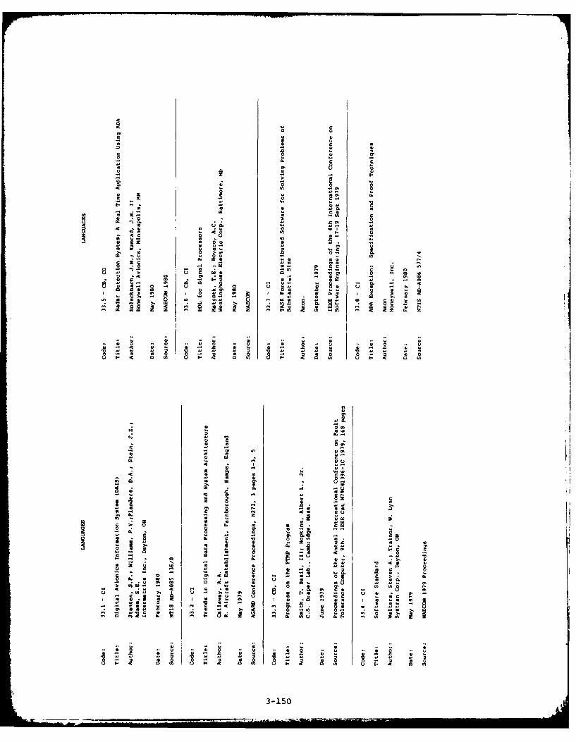
-C
C
0
0.C C; 4
-U 41U
II-
CC 0
UC Co" ', 1 8 " " - -
4. C 0
Cu CO2 00
OVO
CO CC U CC
40 0 -0
a a. 0 4 CC
-C~ CC
.4 we 4
C 24 .0cc 4
4.4
cc -C
V C 3-150
In 4,
00 0
Ic4
.00S4 1
4 004Q0 0) u~ 1-- 0cn t
0 .0
041 0 4
O 0 4 ~ 4m o- 40 c
04 -
-C 40 I- -C a0 4
30 41514 0
.0 .440 4.4 404 4

4 M
-0 0j a
v) 00
tq co 0
c00ac. 0 0. E
U a) 0u 0 w
u -c a ta E -- . -
0 - N- - U
0. c lo .041N L~ 0 0% a,
41 ~ -
0 0 Na; 0o a,60
aa
m t
o o m -0
> 0l 0i -c u
- . ~, a, 2 C % 0 ~u !0 CC .-v 0% u NO0
u" w ON N C N
0I c. Q ~ u8 VI- dcNN C N E ~
U 0~ I, U 0~ I 3 U152

III
4 ,.

Iv
I
Code 34
LARGE-SCALE INTEGRATION TECHNOLOGY
Large-scale integration (LSI) and the emerging very-large-scaleintegration (VLSI) represent state-of-the-art integrated circuitsof particular interest to the AAAS Program. A future technology(late 1980s), very-high-speed integrated circuits (VHSIC) isconsidered beyond the present state of the art, and is notdiscussed herein.
Potential AAAS Applications
- Stores station equipment for analog, digital, and power interfaces
- Stores management integration, including the aircraft system interfaceunit
- Program controllers and distributed processing systems.
Advantages
- LSI (1,000 to 50,000 components per chip) has already proven to be areliable, economic technology for implementing military circuitry. Numer-ous devices of LSI design are available for use in advanced armamentsystems.
- VLSI (greater than 50,000 components per chip) systems should be morereliable than LSI assemblies since they will contain fewer sources offailure, such as power chips and external connections (see Figure 34-1).As particular examples, VLSI would provide increased reliability of fault-tolerant computing and on-chip BITE for functional and diagnostic testing.
- Emerging, smaller VLSI devices provide increased clock speeds in therange of 100 MHz or more.
- Bipolar bit slice components of LSI design increase commonality andstandardization between military and commercial markets.
- Because of the increased number of gates per chip, LSI and VLSI cir-cuitry offer reduced power consumption, weiaht, volume, and cost (see Fig-ure 34-2).
Disadvantages
- No major disadvantages are associated with the use of LSI, except for Fpotential problems of improper device selection by designers.
- The smaller geometry sizes, and hence increased current density, of VLSImakes that technology somewhat potentially less reliable than LSI.
- VLSI technology requires more complex manufacturing techniques, such asmultilevels of interconnections on the same chip. Problems of increasedcontact resistance and instability are the most serious technical issuesto be overcome.
- Parasitic effects of current design may be unforeseen and unrecognized inVLSI circuits.
3-155- . .. .. .. ..fl .... .. " . .... . . ... ..l i . ... . ... .. ... ... III If - i
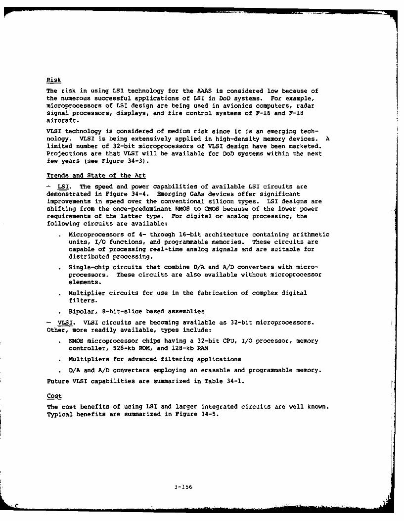
Risk
The risk in using LSI technology for the AAAS is considered low because ofthe numerous successful applications of LSI in DoD systems. For example,microprocessors of LSI design are being used in avionics computers, radarsignal processors, displays, and fire control systems of F-16 and F-18aircraft.
VLSI technology is considered of medium risk since it is an emerging tech-nology. VLSI is being extensively applied in high-density memory devices. Alimited number of 32-bit microprocessors of VLSI design have been marketed.Projections are that VLSI will be available for DoD systems within the nextfew years (see Figure 34-3).
Trends and State of the Art
- LSI. The speed and power capabilities of available LSI circuits aredemonstrated in Figure 34-4. Emerging GaAs devices offer significantimprovements in speed over the conventional silicon types. LSI designs areshifting from the once-predominant NMOS to CMOS because of the lower powerrequirements of the latter type. For digital or analog processing, thefollowing circuits are available:
Microprocessors of 4- through 16-bit architecture containing arithmeticunits, I/O functions, and programmable memories. These circuits arecapable of processing real-time analog signals and are suitable fordistributed processing.
Single-chip circuits that combine D/A and A/D converters with micro-processors. These circuits are also available without microprocessorelements.
Multiplier circuits for use in the fabrication of complex digitalfilters.
Bipolar, 8-bit-slice based assemblies
- VLSI. VLSI circuits are becoming available as 32-bit microprocessors.Other, more readily available, types include:
• NMOS microprocessor chips having a 32-bit CPU, I/0 processor, memorycontroller, 528-kb ROM, and 128-kb RAM
o Multipliers for advanced filtering applications
• D/A and A/D converters employing an erasable and programmable memory.
Future VLSI capabilities are summarized in Table 34-1.
Cost
The cost benefits of using LSI and larger integrated circuits are well known.Typical benefits are summarized in Figure 34-5.
3-156

00Us U
0
* d~
I-D
C4'
U..
00
E-4-i
P( 4 2 ( O J
cl0
C, 14
44
3-15

00
z/
LLnI
U-)
0
ull
LS m
- .
CL V)
LA 0
0 u'2
0'
$2~~ 0 i
0~ LL
LL I-W. _jU 0±V'd~
44
3-15
03

LU
a
a
- > 4 4.
o~~F am. 4,4-
E- CD-(n E-4
A/ Ln . n I
- ~ ~ ~ 3 2 2u i4
3- -1-59. 1

44
N -C C 0- 4,0 0 4
10 >
14 0 4
0 0 0 0 OC IF .
0 w w am 0 C0 0
I Y -m4 u -m- M -C V c w
a 0 4 1 ! w CcM 4 w
4 0 2 - 0 4, 0 2 0z~~1 a -N'aaIn a a- a, 2 * w .
00 'a
0~U
440
-~ ~ 0 cr aa
Sc C 0 U
-~- 0 a .04
za m N C N0 5I. a- v 0 ' 00.0
c 11 c -

C
0c 4!
01 C
~~~ U. 0 -U a
1>, .0 "t'. 0=tP a a C CI 0 0 0
0 U 0 aU ~ U 0 0
C -,C -0 U . -c u. 0 I . C
- 0 k w 0a0 a a, 2. Uaiz o
c. a rC0 ,O ~ - ~ 0 - a
- - - . ; x - ' ~ r - . 0
- 2 0
0m
C 2C9f -
03 16

C U
U 4C .1
E- 41 A.
01 41 1 C a
-~ 0 44
C0
1 41 a) o
0 ;0 0.8 0 0
In 0; 4) 41 C- -Cu z 0 0
11 01 0
0 10 01z 01 a 1 -
uI4 7: 1 0 0 C, 11 1 ='-UI A1 I
u 0 01 0 N040 0 4. U. 41 1
L) UC 04 1.2 341-c o 04W1 12 - 12 In C.1E
41 w C ) '
4.0 4 14 0 1 C0 41 0m0 IF.. 0C
C) I 41 01 - I -C 4 0 I41 4
ZC 0 11 01.40 - CCz-* 01 - * 0
C 0O0r 14 U . 4 a 0U
01
U 41,-
03 0'441 C) 0 0
0 4141 0M 1L! 10
C~> 01 C)
111 41 Sn
v C2 0c -, ft le. ~
- - 41 2' 3-6211

0
0
4,
a.6
U I.-
U U -o -- 0l- a. no 0
- al '.4.5 C. -
0'I ~
N I U M )....U. * *~ a.
.5 - *4U 0 0
a ~ ~ -
7 1 - Io ~ 0*4~ - ,.0 U 0'.4 41 -~ * a'.4 -- 6 U
* 41.0 ~ .5~ .c~ ~
45 .. - p..- 41
.. ~ 41
:1 3-163 4

I
Code 36
MEMORY TECHNOLOGY
This technology brief presents information on semiconductormemories, magnetic bubble memories, and charge-coupled devices.
Potential AAAS Applications
- Data storage and retrieval in the computer and controller areas of processcontrol equipment, stores station equipment, and data transfer equipment
- Refer to Table 36-1 for functional applications.
Advantages
- Semiconductor memories offer high storage density and fast speed, and havea good reliability history.
- Some memory devices can be programmed and erased either electrically orwith ultraviolet light.
- Nonvolatile memory devices are available for airborne applications.
- Static RAM devices have an inherent speed advantage over dynamic devices.
- Bubble devices offer megabit mass storage capability in a small, ruggedform suitable for military airborne applications.
Disadvantages
- Standardization efforts for certain devices have proven inadequate todate.
- Systems designed with memory devices require complex tradeoffs among per-formance, technology, cell structure, and packaging. The numerous cir-cuits and variables associated with memory technology necessitate verycreative designing to prevent improper system designs and applications.
- Bubble devices are an emerging technology, with limited risk informationavailable.
- Charge-coupled device technology is no longer being pursued by manufac-turers as a prime candidate for memory application because of the slowspeed and volatility of these devices.
Risk
Since the semiconductor memory is an established technology, having beensuccessfully applied in numerous aircraft and space applications, suchdevices represent a low technical risk. Care should be taken, however, whenconsidering devices at the leading edge of development. Historically,development goals have usually been met but the projected schedules for thesedevelopments have been substantially exceeded in many cases.
The risk in using bubble memories is considered medium. Although no majorreliability problems have been experienced in commercial applications, mili-tary airborne applications have been insufficient to provide confidence inthe utilizat:66n of bubble memories for the AAAS. However, several high-reliability kpace programs are considering the use of bubble devices inonboard processing systems.
3-165 .

Trends and State of the Art
- Static RAMs. The most prevalent static RAM applications are the 4-kb HMOSand CMOS structures, which have access times ranging from 35 to 75 ns. Bipolardevices, although faster (e.g., 6.5 ns) are limited in availability at thesespeed levels.
Bit-wide static RAMs of l6Kxl organization, fabricated using HMOS, bipolar,or CMOS structures, will be in production in 1981, along with byte-wide staticRAMs of 2Kx8 organization. These latter devices, although slower in accesstime and of higher power dissipation than bit-wide devices, find numerousapplications in microprocessor systems.
- Dynamic RAMs. Dynamic RAMs of 64Kxl organization have power dissipationlevels from 200 to 400 mW and access times from 100 to 500 ns. RAMs having8Kx8 organization are expected to be available in the near future (1981-1982),while growth will increase to 256 kb in 1984 and 1 Mb in 1987.
- Pseudostatic RAMs. Some dynamic memory devices have on-chip automatic orsemiautomatic refresh circuitry and are available in various organizations.
- ROM Memories. NMOS mask-programmed ROMs of 64-kb capacity are available,along with a 256-kb NMOS device having an 80-ns access time.
In development are 128-kb CMOS ROMs having access times of 2 to 20 us and astandby current of 200 uA. International companies have produced 1- to 4-MbROMs of wafer size, as well as a 512-kb ROM chip.
Bipolar ROMs have bit densities of up to 6 kb. No new developments are inprogress in this area.
- PROM Memories. Fuse-link PROM devices have bit densities of from 8 to16 kb. Most PROMs are implemented in Schottky TTL, and achieve access speedsin the 30- to 90-ns range. State-of-the-art 16-kb devices are available in2Kx8 format, emerging in the 4Kx4 format. In the more distant future, 32-kbdevices will be marketed.
- UVEPROMs. UVEPROMs have bit densities up to 16 kb, with 32- and 64-kbdevices beginning to emerge and 256-kb versions expected to be available within5.ears.
- EEPROMs and EAPROMs. These devices have bit densities of up to 8 kb, withat least one type employing NMOS memory cells and CMOS peripheral circuits.
- CCD Memories. Other technologies appear to have nullified the requirementto develop CCD technology. Although some experts take exception to this prog-nosis, the future of CCD memories is uncertain.
- Magnetic Bubble Memories. Magnetic bubble memories are available with bitdensities of up to 1 Mb. Near-term developments will increase the sources of256-kb and 1-Mb devices.
Projected capabilities of various memory devices are depicted in Figure 36-1.
Cost
The cost direction of semiconductor, CCD, and magnetic bubble memory devicesis illustrated in Figures 36-2 and 36-3.
3-166

-j0L
o A
ccN < > 8I 0
O- 0 LI)
LL QQ) 0)w
L le 0 00
0 0
m U) Cl -
00*
E-4-
0 E".C
H . uf
mmE-
- u
CA 00 4 - 1 0
0, 0 0 00
-0 0I
Z 3-16

-400
a4 0
E o 0
W a 0 0~ *0ul S
n z E O
a4 i , <0 <~
0~ ~ Z - - -0c cm0 m .o0
o0 00 0
H 0 0.
7i u 5 31 so a CL
CL 2L E us
-4 0
0n 0 C *
3-168

0
~ 4,
U2 4.
I
0 W 0 -
UW Uo 4 u u
OW. 4,00, . a
z 8- T 5 - A 10
- a, ..a - 0 ,Ua . - a'A 41 06 Uc .41 oOM - U 0 O, o ,- 200,
,3 - Cc 0e1 0
0 UN 0
4 -
3 0 u E
m -l
cd .0 - u
La~~ 4, 0 , 'go 0c 'C
Sul Go C '
U 'U 4, 169

UCIL
ca 0
0 wr
a - 0
OF 0
00
U -
z: o
0 0. Il ! 0C Al
o 0 0 0 0 3010 -~
II
C; z a
2 0
0 gU3 0
.3 Il -1 Z
I. J a 8 'U3
'3-7

I
Code 37
PACKAGING TECHNOLOGY
Advanced packaging approaches for utilization in the SMS aredescribed in this technology brief, together with current trends inproduction for solving interconnection problems. Packagingapproaches of particular interest include the Standard AvionicsModule (SAM), Standard Electronic Module (SEM), Improved SEM(I-SEM), Tape Automatic Bonding (TAB), and chip carriers.
Potential AAAS Applications
- Process control equipment
- SMS interface to data bus
- Control and display equipment
- Power conditioning equipment
Advantages
- SAM should provide optimum packaging techniques for advanced armamentelectronic systems and modular avionics
- I-SEM offers improved cooling characteristics and thermal properties foradvanced armament systems (see Figure 37-1), and increased "pinout"capability.
- Chip carrier technology reduces (relative to the standard DIP) the surfacearea required for attachment of components to boards or substrates (seeTable 37-1). Chip carriers are more compatible with LSI and VLSI devicesthan other packaging technologies.
- CAD/CAM technology allows the use of hardwired electronics at a cost andtime reduction over conventional PCB approaches.
Disadvantages
- Need for industry acceptance of such changes as eventual replacement ofDIPs by chip carriers, and the standardization of pinouts for LSI andVLSI. This situation causes apprehension concerning future availabilityand cost of components for implementing advanced modular packaging.
- The Modular Avionics Packaging (MAP) Program is not compatible with USAFarchitectural concepts due to the use of the I-SEM 2A as the buildingblock. MAP also fixes rack size and allows no installation flexibilityfor the airframe manufacturer.
Risk
The risk in using the above technologies for advanced armament systems isconsidered low to medium. One reason is that certain approaches such as theSAM will require more involved testing and qualification before full confi-dence can be gained. However, SEM has exhibited a very successful opera-tional history.
3-173
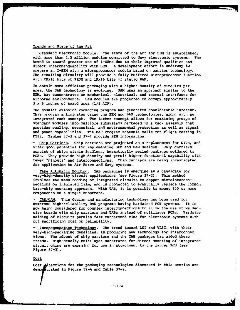
Trends and State of the Art
- Standard Electronic Module. The state of the art for SEM is established,with more than 4.5 million modules committed to Navy electronic systems. Thetrend is toward greater use of I-SEMs due to their improved qualities anddirect interchangeability with SEM. A development effort is underway toprepare an I-SEM with a microprocessor module based on carrier technology.The resulting circuitry will provide a fully buffered microprocessor functionwith 2Kxl6 bits of PROM and lKxl6 bits of static RAM.
To obtain more efficient packaging with a higher density of circuits perarea, the SAM technology is evolving. SAM uses an approach similar to theSEM, but concentrates on mechanical, electrical, and thermal interfaces forairborne environments. SAM modules are projected to occupy approximately3 x 6 inches of board area (1/2 ATR).
The Modular Avionics Packaging program has generated considerable interest.This program anticipates using the SEM and SAM technologies, along with anintegrated rack concept. The latter concept allows for combining groups ofstandard modules into multiple subsystems packaged in a rack assembly thatprovides cooling, mechanical, and environmental protection as well as signaland power capabilities. The MAP Program schedule calls for flight testing inFY82. Tables 37-3 and 37-4 provide SEM information.
- Chip Carriers. Chip carriers are projected as a replacement for DIPs, andoffer good potential for implementing SEM and SAM designs. Chip carriersconsist of chips within leadless, hermetically sealed packages soldered toPCBs. They provide high density and permit higher functional capability withfewer "pinouts" and interconnections. Chip carriers are being investigatedfor application to Air Force and Navy systems.
- Tape Automatic Bonding. TAB packaging is emerging as a candidate forvery-high-density circuit applications (see Figure 37-2). This methodinvolves the mass bonding of integrated circuits to copper microintercon-nections on insulated film, and is projected to eventually replace the commonbare-chip mounting approach. With TAB, it is possible to mount 100 or morecomponents on a single substrate.
- CAD/CAM. This design and manufacturing technology has been used fornumerous high-reliability DoD programs having hardwired PCB systems. It isnow being considered for complex interconnections to allow the use of welded-wire boards with chip carriers and TABs instead of multilayer PCBs. Hardwirewelding of circuits permits fast turnaround time for electronic systems with-out sacriticing cost or reliability.
- Interconnection Technology. The trend toward LSI and VLSI, with theirvery-high-packaging densities, is producing new technology for interconnec-tions. The advent of chip carriers and the TAB packages has aided thesetrends. High-density multilayer substrates for direct mounting of integratedcircuit chips are emerging for use in attachment to the larger PCB (seeFigure 37-3).
Cost
Cost rections for the packaging technologies discussed in this section aredemo trated in Figure 37-4 and Table 37-2.
3-174
.. .. .. . . . . . .. . . . ... .. . ... . .. . I I .. . . .. . . . .. .I

I EnE-
E-
0E-4E-4 H0
/00 . 4
LO H---(
v~a," ~w iln
E-4
C) U) cc
H - "lCL 01 ziZ
Q (r
-~E-t
H 00
C) u
HH Z H 4
x >4C'4 -
E-4
AD-A107 6A0 ARINC RESEARCH CORP SANTA AN A CA F/S 1/3TECHNOLOGY OVERVIEW FOR ADVANCED AIRCRAFT ARMAMENT SYSTEM PROGR--ETC(U)MA Y Al H R OSENBERG, K BRA MAN . P BROOKS NAAG3OBG0-C-O27O
UNCLASSIFIED 178901-124a6 NL
- END3m mm m om o

E-4 1n
c4nf 0
E-4z a~' a 09
a4 u
UJ - 0 0 00 00
-z
o 4)4A 0 ' .
-, m -0aw4
V I s
a Ila
E-4 0
40 u
4U
13.
I a a 2C6) ~
3-176

II
916 PIcI
- *
*0 1 toj0 c1 M - .c
= LI
LI .0 611 1z1 - 4 1
-~~ -aC. v C I
61 - a I 6 I
01 1II4 0
610 ow 14 Fn = .- V * LI 0I j~ 4 rad
u o1 m 96 1 61 I=. JO
61 0 *. LI 01 L
.a 61 - ~ . 61 . 2 0 1707
o ao
01
bc 0
V C m0 C
aC c .-U
0 a9 10 W 0 U
Cc 1 C00 ." 0 0.4 a 4w
w 0, - .'o
t2 0 2 -- ~ ooIK ,,
000 0 0 41 u
01 - l 0. 0
0 .10
0 w
Mo a 0 cc 4 0.
8 8 C aU8- -- a.*~~~ ~~ -l . . .0- 4 ~ ,
0 G -- --- 0ILI

II1E
'06
- U IC3,17

Ii
Code 38
RELIABILITY TECHNOLOGY
This technical brief addresses reliability technology in two areas:recent advances that have the potential of contributing to the reli-ability of SMS, and the latest publications and techniques for sup-porting reliability programs.
Trend Information
There is increasing reliance on software for organizing and speeding the useof reliability-oriented procedures originally developed for manual manipula-tion and for such prosaic purposes as the storage and retrieval of data files.Software reliability technical references have experienced significant refine-ments in recent years. Finally, the reliability of software itself continuesas a research and development concern. A listing of areas in which advanceshave been made are:
Application of graph theoretic methods of network reliability analyses
Application of Fourier series to Bayesian techniques
Application of Boolean/switching algebra to the reliability analysis ofcomplex networks
Continued development and availability of computer programs for perform-ing system reliability predictions
* Continued development of computer programs for performing exhaustivetie-set and cut-set enumerations for complex systems
* Application of data management systems to searching and scoring FMEAand other tabular analyses.
Many of the programs mentioned above require failure rate estimates as anoutput. These estimates can be obtained as computer products. Many compan-ies have automated the procedures for performing reliability predictions inaccordance with MIL-HDBK-217. In addition, Defense contractors can obtainaccess to a government-owned prediction program (RADC-ORACLE), which is resi-dent on the Rome Air Development Center computer.
Other examples of automated reliability analysis support are the MicrocircuitReliability Analysis Program (MRAP) and Semiconductor Reliability AnalysisProgram (SRAP). These programs compare an inputted parts list to a data baseand, for each part, lists whether or not: a military specification is avail-able, a QPL source exists, an alternate military specified part is recom-mended, the device is recommended for new designs, and if a standardizationactivity is planned. Besides their use in evaluating proposed program partslists, the programs are used to generate listings to aid designers in select-ing parts. One listing provides a functional description, specification andslash-sheet designator. It also provides a recommended substitute if a par-ticular device is not recommended for use in new designs. A second listingprovides cross-references to the data by commercial or generic part number.A third listing cross-references the military specification/slash sheet desig-nator and generic number by DESC drawing number.
3-181
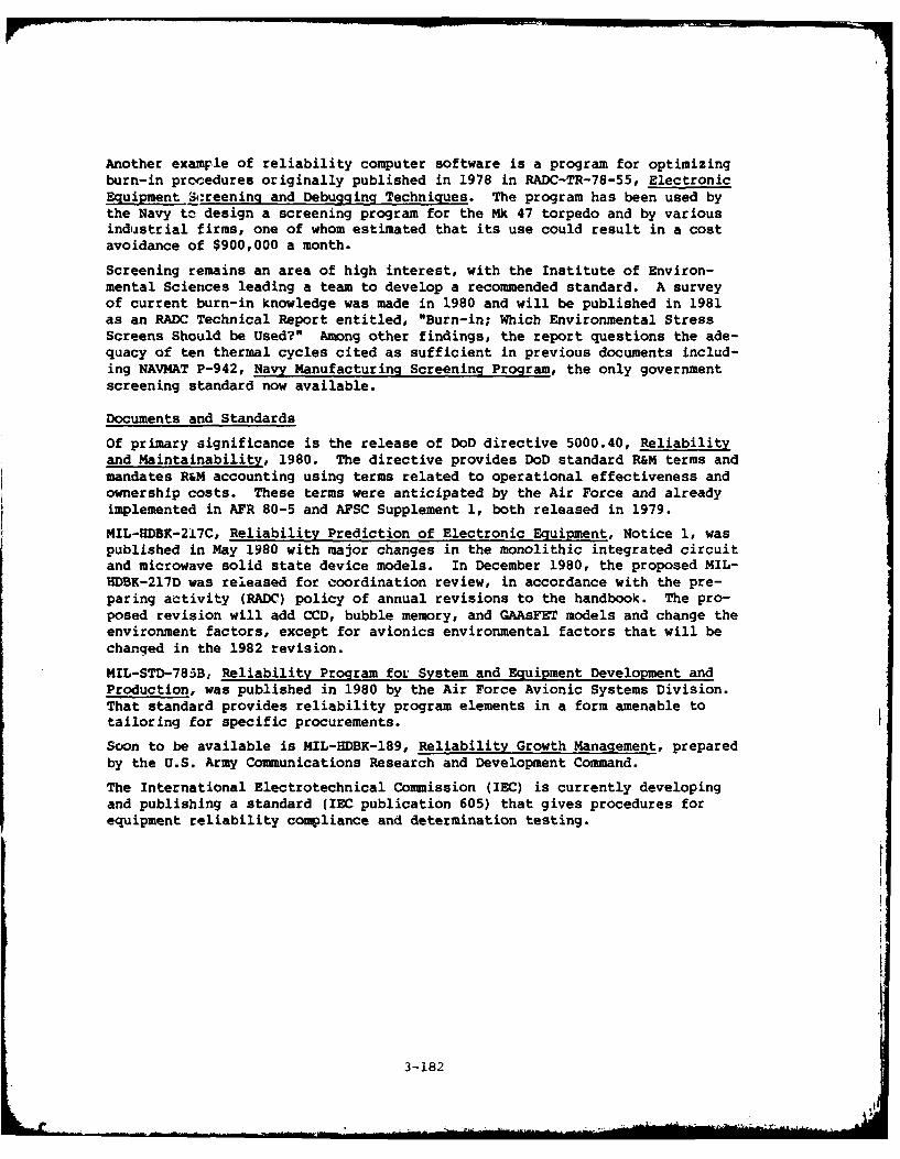
Another examFle of reliability computer software is a program for optimizingburn-in procedures originally published in 1978 in RADC-TR-78-55, ElectronicEquipment Screening and Debugging Techniques. The program has been used bythe Navy tc design a screening program for the Mk 47 torpedo and by variousindustrial firms, one of whom estimated that its use could result in a costavoidance of $900,000 a month.
Screening remains an area of high interest, with the Institute of Environ-mental Sciences leading a team to develop a recommended standard. A surveyof current burn-in knowledge was made in 1980 and will be published in 1981as an RADC Technical Report entitled, "Burn-in; Which Environmental StressScreens Should be Used?" Among other findings, the report questions the ade-quacy of ten thermal cycles cited as sufficient in previous documents includ-ing NAVMAT P-942, Navy Manufacturing Screening Program, the only governmentscreening standard now available.
Documents and Standards
Of primary significance is the release of DoD directive 5000.40, Reliabilityand Maintainability, 1980. The directive provides DoD standard R&M terms andmandates R&M accounting using terms related to operational effectiveness and
ownership costs. These terms were anticipated by the Air Force and alreadyimplemented in AFR 80-5 and AFSC Supplement 1, both released in 1979.
MIL-HDBK-217C, Reliability Prediction of Electronic Equipment, Notice 1, waspublished in May 1980 with major changes in the monolithic integrated circuitand microwave solid state device models. In December 1980, the proposed MIL-HDBK-217D was released for coordination review, in accordance with the pre-
paring activity (RADC) policy of annual revisions to the handbook. The pro-posed revision will add CCD, bubble memory, and GAAsFET models and change theenvironment factors, except for avionics environmental factors that will bechanged in the 1982 revision.
MIL-STD-785B, Reliability Program for System and Equipment Development andProduction, was published in 1980 by the Air Force Avionic Systems Division.That standard provides reliability program elements in a form amenable totailoring for specific procurements.
Soon to be available is MIL-HDBK-189, Reliability Growth Management, preparedby the U.S. Army Communications Research and Development Command.
The International Electrotechnical Commission (IEC) is currently developingand publishing a standard (IEC publication 605) that gives procedures forequipment reliability compliance and determination testing.
3-182

09
Ol 24
I- 20 QC6O
2-0 c -
C 0 =. 0 we
a -C I
I. a 00 0 O
~14 -. 4
-c 0
2. - . 0 * I 0
*3 C"43
14 0
0 3 0 *
0 * 3 ( -
10~I ,
0 0. 34183
3.03 U- 2I

AU
.4 C
I.1U
C
Ia
A 'I.4 ~.o .4
E a.~. U
.04 EU-a. ~-3 N
* ~ N- ~ N* 54 U -~ - 54 a- 0 C - a. -- b - U -.
~ J .la.U a - a. 8 '
- .~ -- '7. ~. -- I a -- 4
~ I ~ I~ -w -, ~ £8 ~
8 -~ a
A* * -4U N 0 .4- a. .4
I -4 -4C = .4 .0* - U 2- * 4. .4
I. a. 4~* .4
Ua N -
.4 0 1o -4
0a - - -
a - N-4 0 - * 0 *4
-4 -4
I 0
.4 -~
0 1. .4
U C a.4- .C .4 1 .4 .C '4 3.4
* S ~ 0 U - - ~.-
I, ~ 4~ U I.. 4~.4 U .4~ .-. 1 0.4 C A -~ - - .a. N
S I 8 0 -- S - 47 M
- .4 U U 0 .~ U U .- a. N
- s: -~ . ~.
- U e ~ .4 - U - a. * 8 ~ -8 ~- - I b~ 4~.4u~ ear. - - 0.4 U § ~ 8!
- . : ~N I* a A 1.44..
a. a '70 -4 U ~ ~. N j
-~
-8 - - 8 U~3-184

I
Code 39
SOFTWARE TECHNOLOGY
Software applications and trends, as relevant to the AAAS, arediscussed in this technology brief.
Potential AAAS Applications
- Operating systems that provide top-level control
- Applications programs that perform the major SMS functions.
Advantages
- A single processor can accomplish multiple functions with software modulesthat would otherwise require more and bulkier hardware elements.
- Software technology provides the capability of accomplishing/monitoringroutine navigational functions, thus allowing the flight crew more timefor non-routine armament tasks.
- Fault-tolerant software architectures will increase the probability ofmission success through increased advanced armament system reliability.
- Distributed software architectires lend themselves to adding or modifyingfunctions.
Disadvantages
- The use of software instead of hardware for advanced armament system func-tions increases the cost of software development and maintenance. Thecost is even greater for centralized architectures.
- Distributed architectures require more exhaustive testing of software mod-ules at an earlier stage of development, thus necessitating earlier avail-ability of test facilities and simulation techniques.
Risk
Utilizing software instead of hardware to accomplish aircraft armament func-tions is considered of medium risk. As they become increasingly complex,advanced aircraft armament systems will also become less understandable andmanageable unless discipline is applied early in their design. Concepts ofsoftware modularity will help alleviate this problem. Other techniques thatwill reduce the risks associated with increasing complexity are the use ofdesign management aids, e.g., requirement statement languages, high-orderlanguages, and structured programming.
Trends and State of the Art
The refinement of current design aids and techniques will provide more reliable/maintainable software and will also help to offset the increasing costs ofsoftware development. The current emphasis on software modularity and struc-tured programming will continue. Modularity and structured programming bothimprove the maintainability of software.
3-185

The use of program design languages, such as PDL, are also gainingpopularity. This tool provides a more thorough overall design early in thedevelopment of the software system. The "chief programmer" approach, top-down design philosophy, and peer design walkthrough are also softwaredevelopment techniques required of many projects, which result in a moreorderly design.
The advent of software configuration control has helped to control andmonitor the progress of software projects. Future enhancements of softwareconfiguration control will be methodologies for accessing the impact of pro-posed changes/enhancements on software that is already operational.
Advances in the hardware/software architectures have not kept pace with indi-vidual hardware/software techniques. However, microprocessor manufacturersare beginning to pay more attention to this area, as is evidenced by thehosting of HOL interpreters on the microprocessor itself. One manufacturerhas built a Basic computer Language interpreter into a chip. Anothermanufacturer has developed a chip that has type checking and multitasking onthe chip in preparation for direct translation of high-order languages.
The software resident in the AAAS should be coded in HOL for easier access,and will be modular in nature to facilitate changes and validation.
Other software trends include component software such as file management andprotocol procedures that can be easily tailored to a user's particularrequirements. Standard interface rules (the "software bus") will ensurecompatibility between software components.
Cost
The overall cost of avionics software/hardware architectures will rise, butwith the refinement of software development tools (see Figure 39-1) notnecessarily in the same proportion as functionality. The increased use inAAAS of multifunction displays and controls will drive up software costs.The reduced workload benefits to the flight crews need to be weiyhed againstthe costs of implementing this custom-designed software. The improvement ofsoftware development tools and development methodologies will help keepdevelopment costs at a manageable level. More aggressive quality controlprocedures are being achieved during the software development phase, whichimproves reliability and maintainability, both of which will help to minimizesoftware maintenance costs. Automatic programming (i.e., automated softwarecode generation directly from user specified requirements) will reduce systemdevelopment time and cost.
3-186

IuIcI<I0
a4
LamC
a,-
C, -4
3-187

o 0f 0
a: c 4o
oL oLiV 0' 0. m v
U C
=0 w 0 0
00 CL -0 CtC CL C C C
C C) V
C1 CL
a c'C
0 a c 0 -
CL 0 0i C C
Ic 3 fL C 2 u - I- 0 C
- . 0 3a 3 0 3-188
1 a
C C£
w -C -
0 >0
I-. c =44c
- 22
V - 0
; 0 4
o d00
0 0'
A I - I
*.ot,~t . C .0c,0V '
U * ~ 30189

0 41
a a
.61
* Cc
3 - - -2' r ,L- a - -4
soA
.0~1 -C
Ih A .0 ~ 3-190

u ID
- -
* 4 0
.CC
o al
A. a
a - I
£ 41
-C 1
a (1 0 091

Code 40
SWITCHING TECHNOLOGY
This technology brief provides a state-of-the-art review of highpower switching technology, with particular attention to solidstate devices.
Potential AAAS Application
- Power conditioning equipment for advanced armament systems
Advantages (Bipolar vs. MOSFET Devices)
- Bipolar transistors provide higher current and voltage, are current-controlled, have lower forward voltage drops, cost less, and have an estab-lished reliability history.
- MOSFET devices have faster switching speeds, are less susceptible tosecondary breakdown failure (see Figure 40-1), require less drive power,are voltage controlled, and are compatible with CMOS and TTL because oftheir higher input impedance.
- The use of MOSFETs in switching power supplies reduces power dissipation.
Risk
The risk in using the power semiconductor switches described herein for SMSis low due to extensive successful military applications.
Trends and State of the Art
Solid-State Components
- Bipolar Power Semiconductor Switches. Typical devices are capable ofoperating in the 50-100 kHz frequency range, and can carry 40A of current atup to 600V. Some devices can carry 8A at voltages of 900, 1,200, and 1,500;and Darlington bipolar devices (see Figure 40-2) can carry up to 20A at 850Vand 60A at 250V. One company has announced a 100A Darlington rated at 900V.
Trends in bipolar development are toward increasing speed to make them com-petitive with FETs. One such device in development has been demonstrated tooperate at 0.5 MHz, and has current ratings varying up to 30A for voltagesfrom 40 to 450. For power applications where speed is not critical, bipolarsexist that are rated at 200A peak at 450V. One foreign supplier claims tohave a transistor in limited quantity that is rated 300A continuous (450Vpeak).
- MOSFET Power Switches. Fast-switching MOSFET devices (Figure 40-3) aretypically rated at 28A at 60V, or 11A at 400V. New manufacturing techniquesand material improvements are beginning to yield MOSFETs having higher currentsand voltage.
The earlier VMOS structures are competing with newer DMOS and TMOS types thatprovide current ratings (pulsed) of 16A at 400V. These devices exhibit for-ward voltage drops comparable to those of bipolar types.
3-193
Numerous lower power FETs are available with typical characteristics of 40 nsswitching speed at currents (continuous) of 4A from 40 to 80 volts. Thesedevices are emerging in production quantities, with trends toward higher volt-age and current without sacrificing speed.
- Thyristors. These high power devices, also referred to as SCRs, havecapabilities up to 2 kV (standoff) and up to 10 kA peak current capacity. Aunique aspect of SCRs is the ability to be triggered by a laser light source.
- Hot Carrier Diodes. These devices, also known as Schottky diodes, operateat very high frequencies, although limited to 75A at 45V (breakdown). Theyhave a forward voltage drop half that of a PN junction diode.
- Standard Diodes. Fast-recovery diodes are emerging having speeds of 50 to70 ns, with capability of 30 to 70 amperes at high voltages. Variations ofthese devices have voltages up to 600V, and current ratings up to 100A.
Cost Direction
Bipolar devices are less expensive than MOSFETs. A rule of thumb for pricingis that off-the-shelf power transistors rated at 100A and up cost between $1and $2.50 per ampere. It is anticipated that solid-state switches will becomeless expensive than their electromechanical counterparts.
3-194

E1-4
E -4
-)g
>4I44
o' 04- 0
0- 0
0 >4
~z 00A 0 E
( Lu
-4
3-195

00
CC
o o 4c. z
161
400
.0c 0 4
. 4% 41 "0 oc Qo0
C 41
.tp.C; l 0
- C c
u .4 I&
12 a
41 A 0.141 0
C;.a WOa2
C 41. - 3 C196
* U NV 0 C * . ~ 0 -ho4

ca a:
CC 11
c 0
Zz "-
lol
0'0
2 gor a o 13wo 0
A o. 64co N 0.
3 El3-197

Code 41
LASER TECHNOLOGY
This technology brief addresses laser emitting sources for applica-
tion to fiber optics data links, as described under Code 32.
Potential AAAS Applications
Laser technology as it pertains to fiber optics is potentially applicable todata transfer equipment of the AAAS.
Advantages
- Laser emitters have a higher degree of waveguiding than is available fromcurrent LEDs, and thus offer better coupling efficiency.
- Because of the ability of laser emitters to produce higher output levelsthan LEDs, using comparable input power, attenuation losses are overcomeand overall system efficiency is improved.
- Lasers have faster rise and fall times and greater bandwidth performancecharacteristics than LEDs.
Disadvantages
- Laser outputs degrade with time and vary with temperature (seeFigure 41-1).
Risk
The risk in using laser devices rather than LEDs for advanced armament sys-tems is considered medium because laser technology is still evolving (seeprojections, Figure 41-2). No reliability information is available for mili-tary applications, nor has the ability to meet Mil-qualification requirementsbeen demonstrated. However, aE least one supplier claims the capability ofproducing a reliable laser transmitter having an output power of 5 mw cw andan operational life of 100,000 hr. Because the telecommunications market forfiber optics is so universal, use of lasers is expected to become a success-ful, standardized alternative to LEDs, which should benefit the AAAS Program.
Trends and State of the Art
- New materials of indium-gallium-arsenide-phosphide (InGaAsP) and GaAsPare being used to produce laser emitters. Most LEDs use GaAIAs.
- Lasers are being incorporated into complete package assemblies thatinclude cooling elements, thermistors, detectors, and signal interfacedevices. The packages are coupled to a fiber optics pigtail for directconnections to other optical components.
- Developmental devices are available having 1,300-um wavelengths, CW oper-ated. These lasers incorporate a stripe-contact that confines the activelasing region of the junction to a narrow section of the emitting facet.
3-199

Cost
The cost of implementing laser emitters for fiber optics applications is highcompared to that of LEDs. However, as the technology evolves and is suitablefor mass production, the cost is likely to decrease, as has been observed forfiber optic semiconductor devices; see Code 32 discussion.
3-200
--------------------------------------

E.
V)
:3 w
-z E
o a~
2-c*
C CD
lz
E-
et
a ~L4
0
Ru u
-i
MAIIdl WSMAU 1VO0UdO
3-2 01

.0
0.
0 0 a .
0 .0 1 I
0 000
I, u
4, 0 0 Q
v v0 0> 0
-0 0 0 1., -
o ~ ~ 0 L. . b04 33
c I 3a~ 0 '-
o 0 to
063-. -C-
Me .M 0 0 0c-
IV S 4 8 0- U' 0 3
U E E. a - ~ L 4> -a a -
.8 I b 43c~8 .8 8
U & Ci ~ U 63 C N U UU V34202

APPENDIX A
TECHNOLOGY MATRICES
A-i
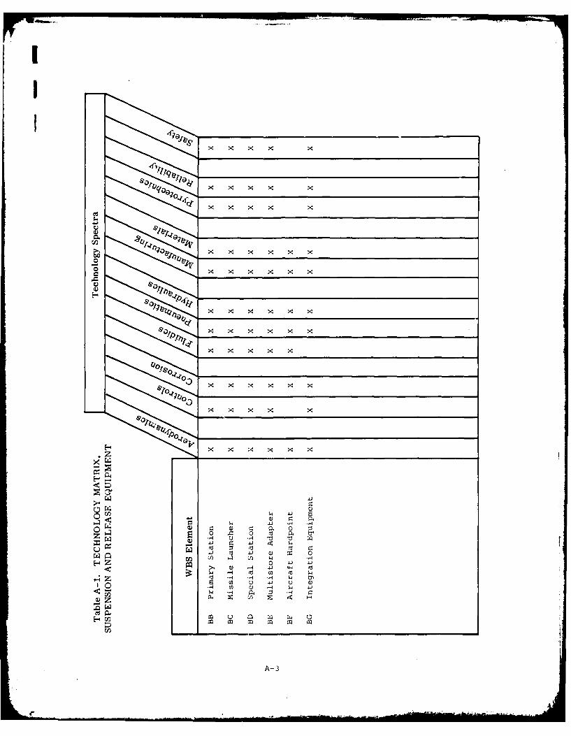
ao
x x x x x
x x x x x
x x
w 4J
U Q)
c) 41 4-
0) r.U4 41 .,
rJ2 ~ ~ ~ ~ ~ ~ ~ 1 __ _ __ _ _ __ _ _ __ _ _ __ _ _ __ _ __0_ _
0 -a 0 M-3
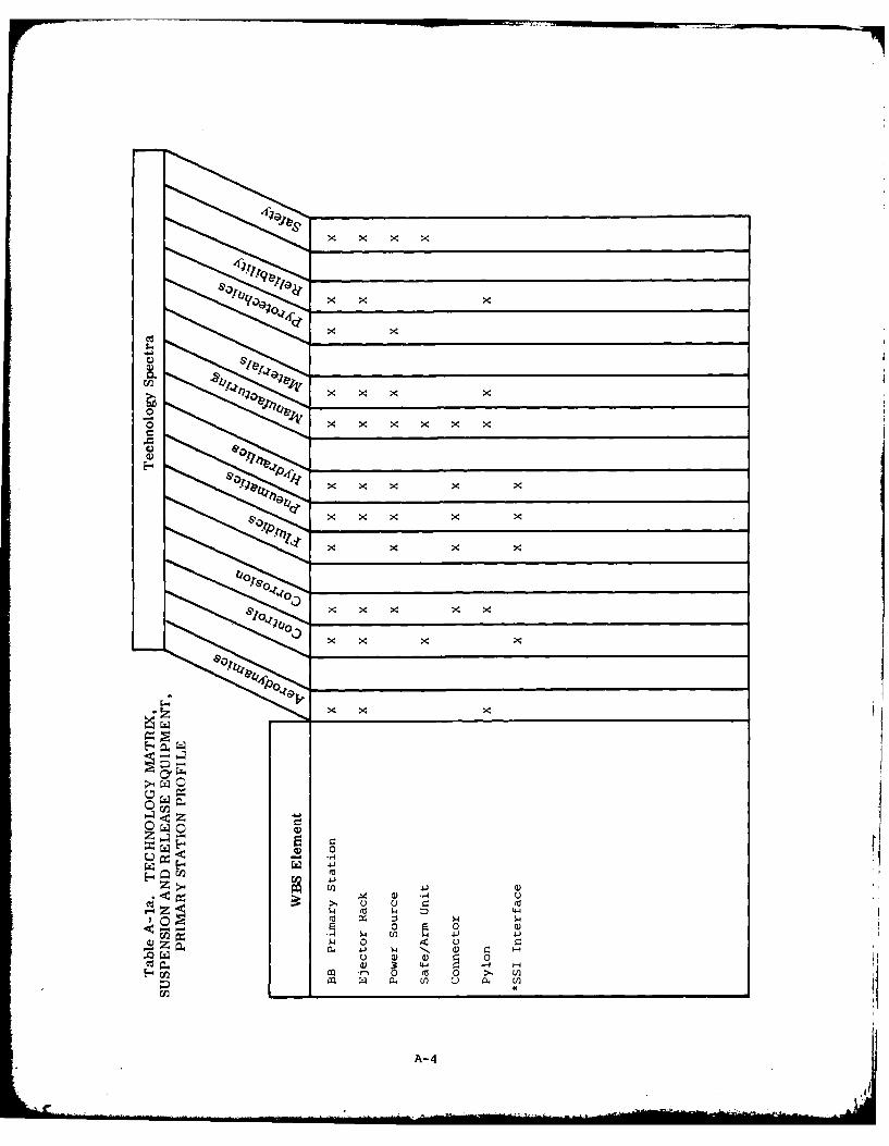
xx x
x x x'
x x x
x x
x .-4x
&0x x
C))
(D -4 u': C
0 0) a)-43 -4 41 '41
ca ) L) la,
A-4

x x x
xx x x x
x x x x
6,10< x x
>x x x x
0 4 9 V
z k- -4 -0
4 -
U4 (a V4 4 -)L
.1 0a) J - 4
vi 0 -4,-
A- 5

xx x x x x
kril
00 0)01
&. x x x '0 xA l) x - Ux x ~ )4x x0
&0)
x x x - x

x x
r~
0x x
W4 U) 4)
0. 0W
Z4I) U) 0 *r a
0 U) l)
A- 7

x x
xX
. W) 4 dJ
6,10 Al 0 xx
Z 0- 04 -
41 0 CZ Cu
A-
0, . . t

Cx x x
x x
x x
x
x >x
>4J
0 H-6 0
w 0w -
(0 0 1
A-

IIx
X >4x x x
0J
x x
., 4.) x. U) x
S1 -4 . C!)-01 U ) ) 4- -
x) xJ 0 >4 U
1-4 -4 0'V0-4 U I )
U) ~ ~ ~ r 4J 4.41 .4 ) U
VI~~w 0- z- ) -4 Q ) UU) 0) r-z 0 4-) E
1-4 0 w) 0 H-3 )U1 A (L) x- 4-' 0 ) tr >
U -4i .- U) u Z - -
En4 0 (n p) 41) 0) CU (1) U)a) U4 CU) 0 w/ 0. a ) Q)~
0 Z 0 41i Cii H-
A-11

x x
04 x
x~ 0
x x
x x444- -t
a, 9tlO 11.10, 41 x
02 040-~a E4 00 4)
1-4 l4z i 0
00 0 0 -
a) 0 -s) 0 '
u w-012

Q x x x
- 'U
444
00
0 U00
U U U
uA- 13
rn 04

x~ x
x x x
3-I& "140 .- 4~ 7- x
0) 0) x' 0 ) ~0~~~0 .). -. 9 0 3' - 0,
&17 Q, x x '- c. x U
A- 14

p4-
4..
7;-'-
0q; >e
.tq
C) C)
,i 3, x) x4-C ZZ-
4.)
4-4
-i0 Q) (fl
- 4 -
Cd 04
A-15

00 ~ -~ -00--
CC.)
N 0
4- 44~
n 0
CA-3
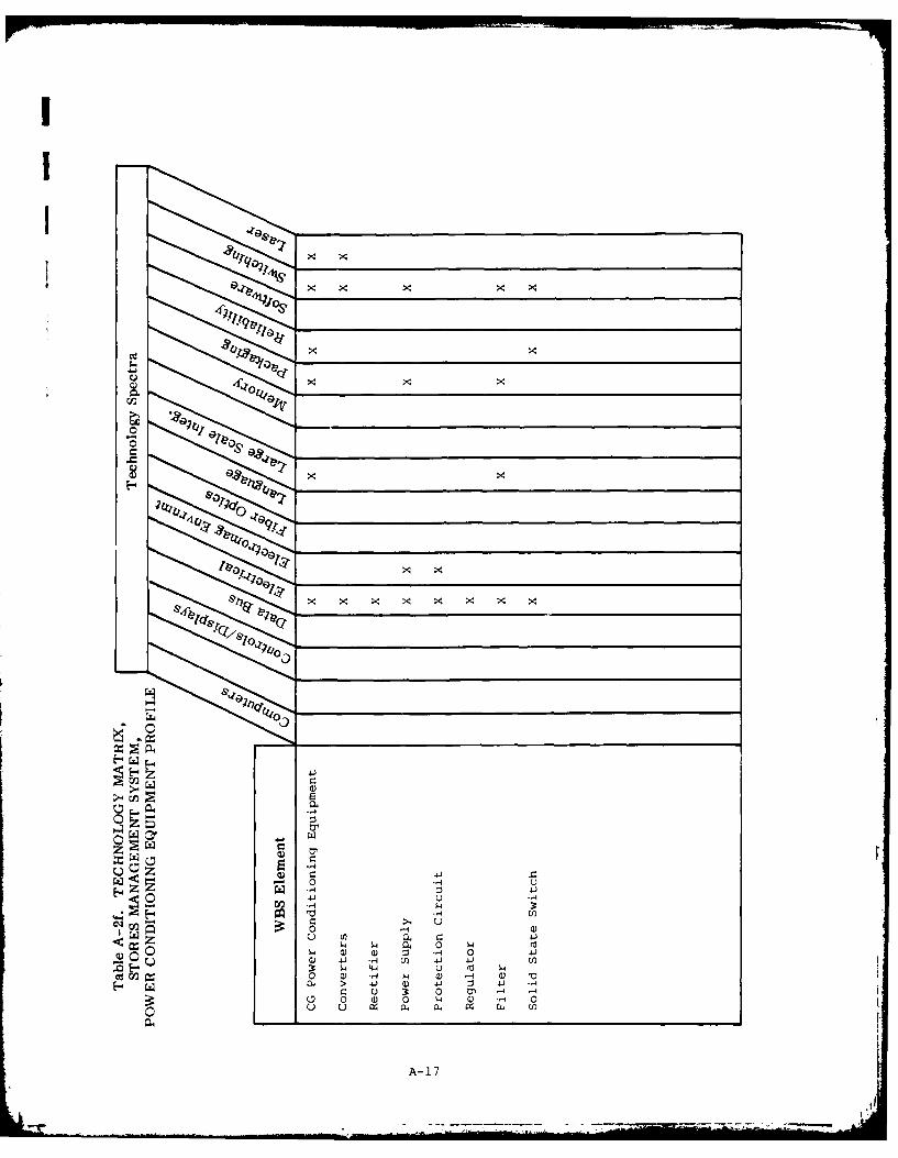
x x x x
Cd x x
x x
0 9E ~ b.0 xz *
rzI >1
1-1 Q
Q) W z -14 0 4
w- 4-4 0 m -c~I~0 a) -14 1-. (1 -4 a~-. Q~ > 41i a 41~ 4:
0 0 4 0 -A -
U~ia U4 c..
A- 17
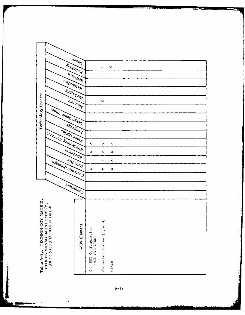
X
H4 4
b1 Z -t-
O 0
444~
-0 m~u U u
A- 18

.8 Olty x x
vvx
09"
C's >,X
~cJS w
t ~ .4 4.2
000
0 (d
UO4F. ) .1 u
4. tp u
r. x (o r. a 1
S -4 0 uNN. 0 -4 a) "I
(a
00U
0A -9

GqL
0.~~~~~~~q r______________1________
44-
&10
LZ 0v 0 LW
.14 z. cH 4.
(/ ~ 4 4 1 0 0 (d
cn U) -4 u 4,4
41 0)-H t 0) 4- W Q)aJ. -- 4 )41 04
4J (D' r. IV (a~ 0 0 --U w)0 a) ) 0 a) w
A- 20

r
I
AP: NDIX B
KEY WORD/PHRASE LISTING
B.1 SUSPENSION AND RELEASE EQUIPMENT
1. AERODYNAMICS
Airborne, Aircraft, Aircraft Carriage Compatibility, Aircraft Weapon
Carriage, Airplane, Analytical Technique, Captive Load, Carriage
Drag, Dispenser, Flutter, Installed Load, Launch Disturbance, Launch
Dynamics, Launcher, Models, Pylon, Rack, Rail, Release Envelope,
Skin, Stores Carriage, Stores Separation, Tip Off, Trajectory Anal-
ysis, Weapon Ballistics, Wind Tunnel
2. BACTERIA
3. CONTROLS
Aero, A.rborne, Aircraft, Armament, Arms, Automatic, Bomb Rack,
Digital, Electrical, Electromechanical, Fluid, Fluidic, Load,
Mechanical, Missile Launcher, Override, Pressure, PSI, Remote,
Sensors, Stores Temperature, System Device, Valve, Weapons
4. CORROSION
Airborne, Anodic, Cathodic, Cationic, Coating, Connector, Control,
Fatigue Loading, Galvanic, Inhibition, Maintenance, Mechanical,
Ocean, Painting, Plating, Prevention, Protection, Replacement
Material, Resistance, Sacrificial Material, Salt, Sea, Stress,
Stress Cracking, Wear
5. ENVIRONMENT
B-1
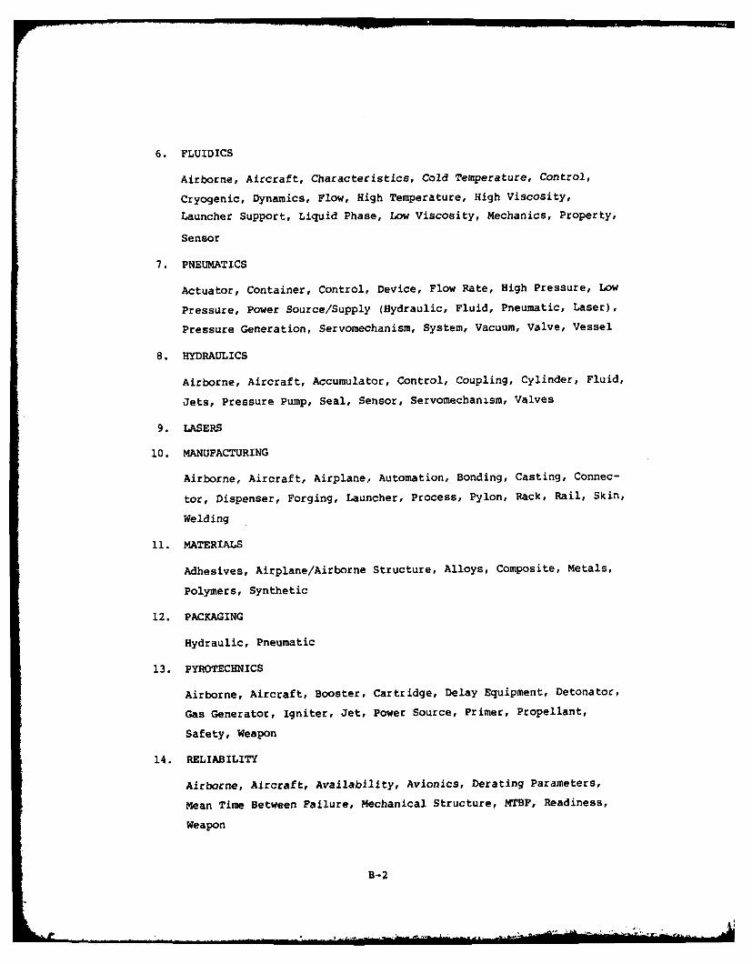
6. FLUIDICS
Airborne, Aircraft, Characteristics, Cold Temperature, Control,
Cryogenic, Dynamics, Flow, High Temperature, High Viscosity,
Launcher Support, Liquid Phase, Low Viscosity, Mechanics, Property,
Sensor
7. PNEUMATICS
Actuator, Container, Control, Device, Flow Rate, High Pressure, Low
Pressure, Power Source/Supply (Hydraulic, Fluid, Pneumatic, Laser),
Pressure Generation, Servomechanism, System, Vacuum, Valve, Vessel
8. HYDRAULICS
Airborne, Aircraft, Accumulator, Control, Coupling, Cylinder, Fluid,
Jets, Pressure Pump, Seal, Sensor, Servomechanism, Valves
9. LASERS
10. MANUFACTURING
Airborne, Aircraft, Airplane, Automation, Bonding, Casting, Connec-
tor, Dispenser, Forging, Launcher, Process, Pylon, Rack, Rail, Skin,
Welding
11. MATERIALS
Adhesives, Airplane/Airborne Structure, Alloys, Composite, Metals,
Polymers, Synthetic
12. PACKAGING
Hydraulic, Pneumatic
13. PYROTECHNICS
Airborne, Aircraft, Booster, Cartridge, Delay Equipment, Detonator,
Gas Generator, Igniter, Jet, Power Source, Primer, Propellant,
Safety, Weapon
14. RELIABILITY
Airborne, Aircraft, Availability, Avionics, Derating Parameters,
Mean Time Between Failure, Mechanical Structure, MTBF, Readiness,
Weapon
B-2

I
I15. STRUCTURES
16. SAFETY
Arms, Handling, Loading, Stores, Weapons
B.2 STORES MANAGEMENT SYSTEM
26. COMPUTERS
Airborne, Aircraft, Architecture, Armament, Avionics, Cost, Distrib-
uted Process, Electrical, Failure Mechanism, General Purpose, Input
Devices, Integration, Interface, Keyboard, Manufacturing,
Mechanical, Memory, Microprocessor, Minicomputer, Missile Launch,
Mission, Multifunction, Network, Programmable, Reliable,
Reliability, Safety, Shared, Signal Processing, Weapon Release
27. (Not used)
28. CONTROLS/DISPLAYS
Calligraphic, Computer, Group, Heads-Up, Indicator Lights, Matrix
Displays, Moving Target Indicators, Multifunction, Screens,
Television
29. DATA BUS
Airborne, Aircraft, Avionics, Cable, Circuit Protection, Connector,
Communications Network, ICD, Integration, Power Supply, Signal
Synthesis
30. ELECTRICAL
Amplifier/Driver, Avionics Regulators, Avionics Relays, Avionics
Switches, Avionics Transformers, Converter, Cost, Fuzing, Multiplex
Terminal, Power Supply, Reliability, Safe/Arming, Signal Conditioner
31. ELECTROMAGNETIC ENVIRONMENT
Aircraft, Armament, Cables/Shielding, Compatibility, Electro-
magnetic Radiation, Hazard, Nuclear Electro Pulse, Ordnance, R&D,
Safety, Specification/Standard, Vulnerability, Weapon
B-3
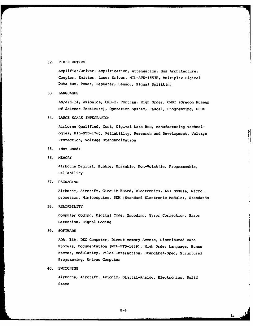
I32. FIBER OPTICS
Amplifier/Driver, Amplification, Attenuation, Bus Architecture,
Coupler, Emitter, Laser Driver, MIL-STD-1553B, Multiplex DigitalData Bus, Power, Repeater, Sensor, Signal Splitting
33. LANGUAGES
AN/AYK-14, Avionics, CMS-2, Fortran, High Order, OMSI (Oregon Museum
of Science Institute), Operation System, Pascal, Programring, SDEX
34. LARGE SCALE INTEGRATION
Airborne Qualified, Cost, Digital Data Bus, Manufacturing Technol-
ogies, MIL-STD-1760, Reliability, Research and Development, Voltage
Protection, Voltage Standardization
35. (Not used)
36. MEMORY
Airborne Digital, Bubble, Erasable, Non-VolatUe, Programmable,
Reliability
37. PACKAGING
Airborne, Aircraft, Circuit Board, Electronics, LSI Module, Micro-
processor, Minicomputer, SEM (Standard Electronic Module), Standards
38. RELIABILITY
Computer Coding, Digital Code, Encoding, Error Correction, Error
Detection, Signal Coding
39. SOFTWARE
ADA, Bit, DEC Computer, Direct Memory Access, Distributed Data
Process, Documentation (MIL-STD-1679), High Order Language, Human
Factor, Modularity, Pilot Interaction, StandardR/Spec, Structured
Programing, Univac Computer
40. SWITCHING
Airborne, Aircraft, Avionic, Digital-Analog, Electronics, Solid
State
B-4....,I m ... ........ .." ... . I 11 . .. .. l i li i| ... .. . .. .. . " .... . " * " - . ..... .

I41. LASERS
Detonator, Driver, Fuse, Fuze, Laser Fusing, Optical, Packaged Laser
Weapon, Podded Laser Weapon, Power Generator, Power Source, PowerSupply, Self-Contained
B-1
• B-5

I
I
APPENDIX C
DATA SOURCES
C.1 GOVERNMENT-INDUSTRY DATA EXCHANGE PROGRAM
The Government-Industry Data Exchange Program (GIDEP) is a cooperativedata exchange among government and industry participants seeking to reduce oreliminate expenditures of time and money by making maximum use of existingknowledge. The program provides a means of automatically exchanging certaintypes of data essential in the research, design, development, production, andoperational life cycle of systems and equipment.
C.1.1 GIDEP Data Banks
Participants in GIDEP are provided access to four major data banks:
a. Engineering
b. Metrology
c. Failure Experience
d. Reliability-Maintainability
A member organization may participate in any or all data banks by agreeing toabide by the requirements for participation defined in Section 2 of the GIDEPPolicies and Procedures Manual.
The Engineering Data Bank (EDB) contains engineering evaluation andqualification test reports, nonstandard parts justification data, parts andmaterials specifications, manufacturing process information, failure analysisdata, and other related engineering data. The bank also includes a sectionof reports on specific engineering methodologies and techniques, air andwater pollution reports, alternate energy sources, and other subjects. TheEngineering Data Bank is available on 16-mm microfilm. The data bank issupplemented with computerized hard-copy index, abstracts, and hard-copysummary sheets.
The Metrology Data Bank (MDB) contains related metrology engineeringdata on test systems, calibration systems, and measurement-technology andtest-equipment calibration procedures. The Metrology Data Bank is availableon 16-mm microfilm. The data bank is supplemented with a computerized hard-copy index.
C-1
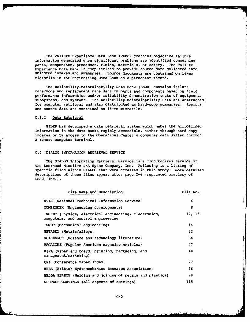
The Failure Experience Data Bank (FEDB) contains objective failureinformation generated when significant problems are identified concerningparts, components, processes, fluids, materials, or safety. The FailureExperience Data Bank is computerized to provide source data collected intoselected indexes and summaries. Source documents are contained on 16-mmmicrofilm in the Engineering Data Bank as a permanent record.
The Reliability-Maintainability Data Bank (RMDB) contains failurerate/mode and replacement rate data on parts and components based on fieldperformance information and/or reliability demonstration tests of equipment,subsystems, and systems. The Reliability-Maintainability Data are abstractedfor computer retrieval and also distributed as hard-copy summaries. Reportsand source data are contained on 16-mm microfilm.
C.1.2 Data Retrieval
GIDEP has developed a data retrieval system which makes the microfilmedinformation in the data banks rapidly accessible, either through hard copyindexes or by access to the Operations Center's computer data system througha remote computer terminal.
C.2 DIALOG INFORMATION RETRIEVAL SERVICE
The DIALOG Information Retrieval Service is a computerized service ofthe Lockheed Missiles and Space Company, Inc. Following is a listing ofspecific files within DIALOG that were accessed in this study. More detaileddescriptions of these files appear after page C-6 (reprinted courtesy ofLMSC, Inc.).
File Name and Description File No.
NTIS (National Technical Information Service) 6
COMPENDEX (Engineering developments) 8
INSPEC (Physics, electrical engineering, electronics, 12, 13computers, and control engineering
ISMEC (Mechanical engineering) 14
METADEX (Metals/alloys) 32
SCISEARCH (Science and technology literature) 34
MAGAZINE (Popular American magazine articles) 47
PIRA (Paper and board, printing, packaging, and 48management/marketing)
CPI (Conference Paper Index) 77
BHRA (British Hydromechanics Research Association) 96
WELDA SEARCH (Welding and joining of metals and plastics) 99
SURFACE COATINGS (All aspects of coatings) 115
C-2

I
C.3 PARTICIPATING FIELD ACTIVITIES
Participating Field Activities (PFAs for this study are listed below,
together with areas of expertise and the prime individual responding torequests for information.
PFA Areas of Expertise Contact
Naval Air Development S&RE gravity rack design and engi- Tom MilhousCenter (NADC), neering, SMS/avionics system
Warminster, PA integration, advanced power systems,
displays/controls, store attachment,
and MSER mods
Naval Ocean System Fiber optics R. D. Harder
Center (NOSC),
San Diego, CA
Naval Surface Weapons Weapon system fuzing, aircraft Ken Brown
Center (NSWC), armament safety, ballistic data
Dahlgren, VA
Pacific Missile Test Aircraft stores interface manuals,Center (PMTC/PM), air-to-air flight testing, SM
Point Mugu, CA integration
Naval Weapons Aircraft stores compatibility andEvaluation Facility interface, aircraft monitor and
(NWEF), control
Albuquerque, NM
Naval Ordnance Station Ejection cartridges (S&RE power Marty Henderson
(NOS/IH), source)Indian Head, 3D
Naval Avionics Center Aircraft monitor and control, air-(NAC/I), borne weapon control and releaseIndianapolis, IN equipment
Naval Air Test Center Ground support equipment, aircraft Norman Davis
(NATC), stores compatibility, separationPatuxent River, MD flight testing
Naval Air Engineering Ground support equipment, engineer-
Center (NAEC), ing specifications and standards
Lakehurst, NJ
DTNSRDC Conformal carriage
Naval Safety Center Safety Mr. Vose(NSC),
Norfolk, VA
C-3

C. 4 INDUSTRY CONTACTS
Industrial sources providing information for this study are listedbelow.
Alkan Corporation ITT Cannon235 Loop 820 N.E. 666 E. Dyer RoadHurst, TX 76053 Santa Ana, CA 92702Kent Goldsmith L. Fields(817) 589-2451 (714) 972-2061
Control Data Corp. ITT Electro-Optical Division5630 Arbor Vitae 7635 Plantation RoadLos Angeles, CA 90045 Roanoke, VA 24019Wally Jones J. Smiley(213) 642-2439 (703) 563-03781
Crouzet Aeronautics and Systems Northrop Corporation5535 Balboa Blvd., 3901 W. BroadwayEncino, CA 91316 Hawthorne, CA 90250John Lent Ron Blakhurst(213) 995-3655 (213) 970-4027
Deutsch Optical Perkin Elmer Corp.Waveguide Systems 2 Crescent PlaceBanning, CA 92220 Ocean Port, NJ 07757(714) 849-7822 (201) 870-4712
EDO Corporation Pyle National Co.13-10 111th St., 1334 N. Koster Ave.,College Point, NY 11356 Chicago, ILL 60651Walter Glover (312) 342-6300(213) 542-5524
Rockwell InternationalFairchild Industries Collins GovernmentStratos Div. Avionics Division1800 Rosecrans Ave., 2201 Seal Beach Blvd.,Manhattan Beach, CA 90266 Seal Beach, CA 90740C. Ballard Edward Martin
(213) 594-2552G&H Technology, Inc.1649 17th St., Sanders AssociatesSanta Monica, CA 90404 Information, Products Division(213) 450-0561 Daniel Webster Highway, South
Nashua, NH 03061Hughes Aircraft (603) 885-528017156 Von Karman Ave.,Irvine, CA 92705 Scot IncorporatedT. Jarnigan 1126 El Camino Drive(714) 549-5701 Costa Mesa, CA 92626
Ben E. Paul(714) 549-2405
C-4

I
Teledyne Philbrick Western Gear Corp.30941 Agoura Road P.O. Box 629Westlake Village, CA 91361 Jamestown, ND 58401(213) 889-3827 George Demos
(701) 252-6250TRW Cinch Connectors1501 Morse Ave. Zilog, Inc.Elk Grove Village, ILL 60007 10460 Bubb Road(312) 921-6151 Cupertino, CA 95014
(408) 446-4666
C.4 BIBLIOGRAPHY
Title
Hydraulic Systems, Aircraft, Types I and II, Design and InstallationRequirements for, 14 September 1979
Coupling, Quick Disconnect, Automatic Shut Off, General Specificationfor, 16 May 1973
Airborne Stores, Associated Suspension Lugs, and Aircraft-StoreInterface (Carriage Phase); General Design Criteria for, 30 January 1979with Amendment 1, 10 August 1979
NATOPS Flight Manual, Navy Models A-7A, A-7B Aircraft, 15 March 1977
Airborne Weapons/Stores Loading Manual, Navy Model A-7E Aircraft,2 June 1972
Flight Manual, A-7D Aircraft, 15 February 1979
Maintenance Instructions, Organizational, Armament Systems A-7D,15 August 1973
Aircraft Internal Time Division Command/Response Multiplex Bus,21 September 1978 with Notice 1 (USAF), 12 February 1980
Standard Store Interface, Aircraft/Stores Electrical InterfaceDefinition, May 1980
Standard Avionics Packaging, Mounting, and Cooling Baseline Study,January 1980
Common Multimode Modular Radar (CMMR) Software Act.isition Study,September 1980
An Overview of Avionics Technologies for the Improvement of All WeatherAttack Avonics Systems (AWAAS), Naval Avionics Center, NAC-TR-2180,
September 1978
AN/AYK-14(V), Navy Standard Airborne Computer, Technical Description,Control Data Corporation, Aerospace Division, Minneapolis, MI,
January 1980
C-5
...." .... .... l/f m ll i"' ;' ... ... ... .. -" --I u," I

Title
MIL-STD-1760 Open Forum Proceedings, Eglin AFB, FL, 28-30 October 1980
Second APSC Multiplex Data Bus Conference, ASD-TR-78-34,10-12 October 1978
Stores Management Systems Architectural Tradeoff Studies, Fairchild
Space and Electronics Co., Germantown, MD, 687-TR-3000, 3 November 1980
Airborne Weapons/Stores Loading Manual, Navy Model F/TF-18A,15 September 1980
Advanced Aircraft Armament System (AAAS) Program Master Plan,October 1979
Contract Development Specification for Advanced Development Model (ADM)Stores Management System, 24 July 1980
Aircraft Armament Interoperability Interface Program (A212 ), Joint
Program Management Plan, April 1979
Technical Description of the Advanced Aircraft Armament System AircraftHardpoint, undated
Technical Description of the Advanced Aircraft Armament System Pylons,
undated
Technical Description of the Advanced Aircraft Armament System Standard
Armament System Interface, undated
Technical Description of the Advanced Aircraft Armament System Standard
Store Interface, undated
A-7 ALOFT (Avionic Light Optical Fiber Technology) Economic AnalysisDevelopment Concept, NELC/TD 435, 7 July 1975
[
C-6
FILE 6
DIALOG* INFORMATION RETRIEVAL SERVICE
NTISFILE DESCRIPTIONThe NTIS database consists of government-sponsored research, development, and engineering reports plusanalyses, journal articles, and translations prepared by federal agencies, their contractors or grantees. NTISalso covers federally generated machine-readable files and software as well as U.S. Government inventionsavailable for liscensing. It is the means through which unclassified, unlimited distribution reports are madeavailable to the public. (In 6.1)
SUBJECT COVERAGEThe NTIS database includes material from both the "hard" and "soft" sciences, including topics of immediate,broad interest, such as environmental pollution and control, energy conservation, technology transfer, healthplanning, societal problems, and urban and regional development and planning. An outline of the subjectcoverage of this file is shown below: (1 6.2)
" Administration * Health Planning" Aeronautics and Aerodynamics e Industrial and Mechanical Engineering" Agriculture and Food e Library and Information Sciences* Astronomy and Astrophysics a Materials Sciences" Atmospheric Sciences * Mathematical Sciences* Behavior and Society * Medicine and Biology" Biomedical Technology and Engineering e Military Sciences" Building Technology e Natural Resources and Earth Sciences" Business and Economics * Navigation, Guidance and Control( Chemistry * Nuclear Science and Technology" Civil Engineering e Ocean Technology arid Engineering" Communication 0 Physics* Computers, Control and Information Theory * Space Technology" Electrotechnology e Transportation" Energy e Urban and Regional Technology" Environmental Pollution and Control
SOURCESSince 1964 more and more federal agencies have been announcing and selling reports through NTIS so thatas of 1977, the NTIS database represents the reports of over 300 federal government agencies. (1 6.3)
DIALOG FILE DATA (, 6.4)Inclusive Dates: 1964 to the presentUpdate frequency: Biweekly (approximately 5,000 a month)File Size: 560,000 citations, as of March 1977
ORIGIN (T, 6.5)National Technical Information Service (NTIS) Telephone: 703/557-4642U.S. Department of Commerce5285 Port Royal RoadSpringfield, VA 22151
*Tradematk Reg. U.S. PIg a Trademurk Office.
C-7
4. . .A

FILE 8
DIALOG* INFORMATION RETRIEVAL SERVICE
COMPENDEX
FILE DESCRIPTION
The COMPENDEX database is the machine-readable version of The Engineering Index*. which provides theengineering and information communities with abstracted information from the world's significant engineeringand technological literature. COMPENDEX provides worldwide coverage of the journal literature, publicationsof engineenng societies and organizations, papers from the proceedings of conferences, and selected governmentreports and books.
(C 8.1)
SUBJECT COVERAGE
COMPENDEX is an interdisciplinary index to the world's engineering developments, including the followingsub," :t areas:
(v 8.2)" Civil, Environmental, Geological and Biological Engineering* Electrical. Electronics and Control Engineeringi Chemical, Agricultural and Food Engineering" Mining, Metals and Fuel Engineering -
* Mechanical, Automotive, Nuclear and Aerospace Engineering" Industrial and Management Applications
( SOURCES
Publications from around the world are indexed, among which are the following types:(0~ 8.3)
" Approximately 1800 journals" Publications of engineering societies and organizations" Approximately 1000 works from conferences, symposia. etc." Selected government reports and books
DIALOG FILE DATA(4, 8.4)
Iclusive Dates: January 1970 to the presentUpdate Frequency: Monthly (about 7,000 citations per month)File Size: Over 550,000 records, as of April 1977
ORIGIN
COMPENDEX is produced by Ei and questions concerning file content should be directed to:("n 8.5)
Mr. John W. Carrigy, Manager Telephone: 212/644-7600Magnetic Tape SalesEngineering Index, Inc. (Ei)345 East 47th StreetNew York, NY 10017
*Trademak Reg. U.S. Pac. & Trademark Office.
c-8 8-1
. . .. . . . . . . .. .. = . . . . I I . . . . .. ... . .. .

FILE 12FILE 13
DIALOG* INFORMATION RETRIEVAL SERVICE
INSPEC
FILE DESCRIPTION
The Science Abstracts family of abstract journals, indexes, and title bulletins commenced publication in 1898.Today it forms the largest English-language database in the fields of physics, electrical engineering, electronics,computers, and control engineering. Foreign-language source material is also included, but abstracted andindexed in English. File 12 includes Physics Abstracts. File 13 is the companion file, including Electrical andElectronics Abstracts and Computer and Control Abstracts. (f 12. 1)
SUBJECT COVERAGE
The principal subject areas are indicated by major headings below, used with the INSPEC database (File 12and File 13): (-F 12.2)
" Atomic and Molecular Physics * Gases, Fluid Dynamics, and Plasmas" Computer Programming and Applications * General Topics" Computer Systems and Equipment * Elementary Particle Physics" Condensed Matter: Electrical, * Instruments and Measurement
Magnetic, and Optical Properties e Interdisciplinary Subjects" Condensed Matter: Structure, Thermal, o Information/Communication
and Mechanical Properties Science and Engineering" Control Technology e Mathematics and Mathematical" Electrical and Magnetic Devices Physics" Electromagnetics, Optics, and Circuits * Nuclear Physics
* Power Systems and Applications
SOURCES
Journal papers, conference proceedings, technical reports, books, patents, and university theses are abstractedand indexed for inclusion in the INSPEC database. The number of journals scanned regularly is approximately2,100: over 340 of these are abstracted completely. (" 12.3)
DIALOG FILE DATA (C 12.4)
Inclusive Dates: 1969 to presentUpdate Frequency: Monthly (approximately 12,500 citations per month)File Size: About 500,000 records in each file, as of May 1977
ORIGIN
INSPEC is produced by IEE and questions concerning file content should be directed to either of the followingoffices: (C 12.5)
INSPEC Market Administrator INSPEC Magnetic Tape ServicesIEEE IEE445 Hoes Lane Station House, Nightingale RoadPiscataway, NJ 08854 Hitchin Herts SG5 IRJUSA EnglandTelephone: 201/981-0060 Telephone: 0462 53331
*Trademark Reg. U.S. Pat. & Trademark Office.
C-9 12-1

FILE ]A
DIALOG* INFORMATION RETRIEVAL SERVICE
ISMEC
FILE DESCRIPTION and SOURCES
The ISMEC (information Service in Mechanical Engineering) database corresponds to the biweekly printedISMEC Bulletin. ISMEC indexes significant articles in all aspects of mechanical engineering, productionengineering, and engineering management from approximately 250 journals published throughout the world.In addition, books, reports and conference proceedings are indexed. These sources are further supplementedby relevant material from more than 2.000 periodicals in physics and engineering that are received by INSPEC.The primary emphasis is on comprehensive coverage of leading international journals and conference% onmechanical engineering subjects. .(C 14. 1)
SUBJECT COVERAGE
The principal subject areas are indicated by the hierarchical classification scheme developed by ISMEC Arepresentative, but not exhaustive, listing of the sections comprising each division is given below- C 14)
*Management and Production *Production Processes. Aerospace Engineering
Management Studies Tools, and Equipment Mechanical Handling
Production Hardening
Forming Processes * Mechanical Engineerine
*.Measurement and Control and Equipment and Natural Resources
Measurement Science Machining and Machine Agriculiural Engineering
Measurement and Conirol of Tools Mining
Specific Variables Joining Processes and Oil and Natural Gas
Measurement and Control Equipment Ecology
Equipment Finishing Processes
Fluidic Devices and Systemns and Equipment o SIechaniical Engineering
Hand Tools in Sioence and Indlustrl
* Mechanics Materials, and Nu..lear Engineering
Devices a Enerty and Power EliriiesI Enigincering
Analyiical Mechanics Thermodynamics Elc. ronic Engsneering
Mechanical Properies and Heating. Cooling. Cisii Emgineering
Effects and Ventilating Opiiia. Engineering
Physical and Chemical Fuel Technology Mediical Engineering
Properties and Effects Engines industrial Process
Materials Testing Mechanical and Fluid Engineering
Fluid Mechancis Power Transmission
Tribniogy a Other -%V2iaions0I
Mechanical Components a Iransoor and Handin MehnL Eniern
Acoustic Devices and Motor Vehicle Engineering Military Engineering
Equipment Motoriess Vehicle Bu'.iie%% Equipment
Engineering Donnestiit Equipment
Railway Engineering Other Special Arphcaiion%
Marine Engineering
D'ALOG FILE DATA Or 14 3)
Inclusive Date% 1973 to the presentUpdate Frequency Monthly (approximately 15,000 citations a year)File Size 58.000 citations. as of March 1977
ORIGIN 14
Data Courier. Inc Telephone: 502/582-4111o.2O South 5th StreetLouisstlle, KY 40202
*Trademark Relt. S Pat. & Trademark Office.
c-1014

32
~METADEX
DIALOG INFORMATION RETRIEVAL SERVICE
FILE DESCRIPTIONThe METADEX (Metal Abstracts/Alloys Index) database, produced by the American Society for Metals(ASM) and The Metals Society (London), provides comprehensive coverage of international metalsliterature. The database corresponds to the printed publications: Review of Metal Literature(I 966-67), Metals Abstracts (1968 to the present), and Alloys Index (1974 to the present). The MetalsAbstracts portion of the file includes references to about 1,200 primary journal sources. Alloys Indexsupplements Metals Abstracts by providing access to the records through commercial, numerical, andcompositional alloy designations; specific metallic systems; and intermetallic compounds found withinthese systems.
Informative abstracts are included for most records since 1979.
SUBJECT COVERAGE
In addition to specialized topics (including specific alloy designations, intermetallic compounds, andmetallurgical systems), six basic categories of metallurgy are covered:
* Materials . Products* Processes * Formse Properties * Influencing Factors
SOURCES'Each month about 3,000 new documents from a variety of international sources are scanned andabstracted for the ASM database, with intensive coverage of appropriate journals, conference papers,reviews, technical reports, and books. Dissertations, U.S. patents, and government reports have beenincluded since 1979.
DIALOG FILE DATAInclusive Dates: 1966 to the present; Alloys Index, 1974 to the presentUpdate Frequency: Monthly (approximately 3,000 records per month)File Size. 405,000 records as of October 1980
ORIGINMETADEX is produced by Metals Information, a joint service of the American Society for Metals andThe Metals Society. Questions concerning file content should be directed to:
Ed Kaminski Telephone: 216/338-5151Manager, Information Services TELEX: 980-619 METALEX-MTPKAmerican Society for MetalsMetals Park, OH 44073
Datala copyrilhted by the Aneican Society for Metals and The Metals Society.
DA Gs- of LMSC, Inc. Reg. U.S. Pat. & Trademark Office.
(Revised November 1980) 32-I
C-i
FILE 34
DIALOG* INFORMATION RFTIr.IEVAL SERVICE
SCISEARCH
FILE DESCRIPTION
SC!SEARCH.is a multidisciplinary index to the literature of science and technology prepared by the Institutefor Scientific Information (IS11). It contains all the records published in Science Citation Index (SCII) andadditional records from the Current Contents series of publications that are not included in the printed versionof SC. SCISEARCH is distinguished by two important and unique characteristics First, journals indexedare carefully selected on the basis of several criteria, including citation analysis, resulting in the inclusion of90 percent of the world's significant scientific and technical literature. Second, citation indexing is provided.which allows retrieval of newly published articles through the subject relationships established by an author'sreference to prior articles. (v 34.1)
SUBJECT COVERAGE
Subjects include the following areas: (4 34.2)
e Acoustics * Biology * Electronics * Medicine * Psychiatry9 Aeronautics * Biophysics * Engineering * Microbiology e Psychology* Agriculture e Botany e -Environmental Science * Pharmacology * Surgerye Astrophysics e Cardiology * Geology e Physics * Virology* Behavioral Sciences * Chemistry * Mathematics e Physiology * Zoologye Biochemistry * Dermatology
SOURCES
The ISI staff indexes all significant items (articles, reports of meetings, letters, editorials, correction notices.etc.) from about 2,600 major scientific and technical journals. In addition, the SCISEARCH file for 1974-75includes approximately 38,000 items from Current Contents - Clinical Practice. Beginning January 1, 1976,all items from Current Contents - Engineering. Technology, and Applied Sciences andCurrent Contents -Agriculture. Biology, and Environmental Sciences that are not presently covered in the printed SCI will beincluded each month. This expanded coverage will add approximately 58,000 items per year to the SCISEARCHfile. (T 34.3)
DIALOG FILE DATA (- 344)
Inclusive Dates: January 1974 to the presentUpdate Frequency: Monthly (about 42,000 items per month)File Size: More than 1,500,000 citations, as of June 1977
ORIGIN
SCISEARCH is produced by ISl and questions concerning the file content should be directed to! (41 34.5)
Mr. Richard Sweet, Manager Telephone: 800/523-1850 toll free; in Penn.Data Base Marketing call 215/923.3300, Ext. 357, collect.Institute for Scientific Information325 Chestnut StreetPhiladelphia, PA 19106
*Trademark Reg. U.S. Pat. & Trademak Office. 34.1
C-12
FILE 47
DIALOG* INFORMATION RETRIEVAL SERVICEMAGAZINE INDEX TM.
FILE DESCRIPTION
MAGAZINE INDEX provides cover-to-cover indexing of over 370 popular American magazines. All articles,news reports, editorials on major issues, product evaluations, biographical pieces, short stories, poetry, recipes.and reviews are included. The only items not included are minor personnel notes, brief bulletins and otherephemera. MAGAZINE INDEX is particularly useful for answering general reference questions; because it in-cludes information not available in any other online database, it provides a valuable adjunct in such areas asmarket research, public relations, government relations, journalism, food and nutrition, and the social sciences.
SUBJECT COVERAGE
The subject coverage of the magazines included in MAGAZINE INDEX can be broken down by the followingmajor groupings:
* General/News * The Performing Arts, Literature* Man and His Society 0 Business* Life and Living * Science and Technology, Agriculture* Leisure Time Activities 0 Consumer Product Evaluation" Home Centered Arts 0 Regional* Sports, Recreation, Travel - 0 Environment
SOURCES
MAGAZINE INDEX provides coverage of the 371 most popular magazines in America and includes coverageof all 173 magazines covered by Reader's Guide.
DIALOG FILE DATA
Inclusive Dates: 1976 to the presentUpdate Frequency: Monthly (approximately 5,000 citations per month)File Size: 58,000 records, as of April 1978
DOCUMENT RETRIEVAL
MAGAZINE INDEX provides a document copy and delivery service for articles from magazines not availablein a local library. The service is provided in compliance with the Copyright Act of 1978 and in cooperatingwith the Copyright Clearance Center. There is a processing fee and per-page copy charge. For further informa-tion contact MAGAZINE INDEX below.
ORIGIN
MAGAZINE INDEX is produced by The Magazine Index, a division of IAC, and questions concerning filecontent should be directed to:
Mr. Dick Kollin Telephone: 800/227-8431 toll free or in Calif. 415,1941-1100Vice PresidentThe Magazine IndexInformation Access Corp.885 North San Antonio Rd.Los Altos. CA 94022
*Trademark Res. U.S. Pat. & Trademark Office
C-13

FILE 48
DIALOG* INFORMATION RETRIEVAL SERVICE
PIRA
FILE DESCRIPTION
PIRA is a machine-readable version of Paper and Board Abstracts, Printing Abstracts, Packaging Abstracts,and Management and Marketing Abstracts. The first three provide abstracts of industry-specific scientific,technical, marketing, and management literature; the last-named covers the general literature and is not slantedto any particular industry.
SUBJECT COVERAGE
The database is divided into four principal subject areas: paper and board, printing, packaging, and manage-ment and marketing. A representative, but not exhaustive, listing of subjects covered is given below:
* Adhesives * Machinery" Binding 0 Occupational Safety* Composition 0 Plastics Packaging* Education and Training * Pollution" Finishing 0 Production* Food Packaging 0 Pulps* Forecasting * Recycling* Graphic Arts 0 Reprography* Industrial Relations 0 Retailing" Inks 9 Testing* Materials
SOURCES
Material in PIRA is gathered from literature published throughout the world and includes over bOO periodicalsas well as books, pamphlets, standards, specifications, legislation, translations, conference papers, researchreports, trade literature, and other information.
DIALOG FILE DATA
Inclusive Dates: 1975 to the presentUpdate Frequency: Monthly (approximately 10,000 citations a year)File Size: 31,000 records, as of May 1978
ORIGIN
PIRA is produced by Pira, and questions concerning file content should be directed to:
Pira Telephone: Leatherhead 761 61The Research Association forthe Paper and Board,Printing and Packaging IndustriesRandalls Road, LeatherheadSurrey KT22 7RU, U.K. Telex: 929810
'Trademark Reg. U.S. Pat. & Trademark Office.
C-14

FILE 77I
DIALOG* INFORMATION RETRIEVAL SERVICECONFERENCE PAPERS INDEX
FILE DESCRIPON
CONFERENCE PAPERS INDEX (CPI) covers about 100, 000 papers of approximately 1,000 scien-tific and technical meetings worldwide each year. Because of the inherently strong interdiscipli-nary orientation of scientific meetings, CONFERENCE PAPERS INDEX is extremely usefulbecause it provides a single index to meetings in all scientific and technical fields. The corre-sponding printed publication is the monthly Conference Papers Index.
SUBJECT COVERAGE
CONFERENCE PAPERS INDEX covers meeting and papers in the following areas:
Life Sciences: Engineering: Physical Sciences:
" Clinical Medicine 9 Aerospace * Chemistry" Experimental Biology e Mechanical * Geosciences
and Medicine * Civil * Physics" Animal and Plant * Electronic * Mathematics
Science * Chemical . Operational Research" Biochemistry o. Nuclear e Materials Science" Pharmacology * Power and Technology
SOURCES
The information included in CONFERENCE PAPERS INDEX is taken from the final program or ab-stract publication of conferences, supplemented by responses to questionnaires sent by CON-FERENCE PAPERS INDEX staff. Each entry includes the title of the paper; name(s) of author(s):conference publications issued or planned for issuance; preprints, reprints, abstract booklets,and proceedings volumes available; dates of availability; costs; and ordering procedures.
CONFERENCE PAPERS INDEX may also include both references to papers presented at confer-ences but not yet published, and to some not intended for publication. Entries include the locationof the author fn. further information.
DIALOG FILE DATA
Inclusive Dates: January 1973 to the presentUpdate Frequency: Monthly (approximately 10, 000 records per month)File Size: 530, 000 records as of August 1978
ORIGINCONFERENCE PAPERS INDEX is produced by Data Courier, Inc., 620 South Fifth Street, Louis-ville, Kentucky 40202.
Questions concerning file content should be directed to:
Information Services Dept. Telephone: 502/582-4111Data Courier, Inc.620 South Fifth StreetLouisville, Kentucky 40202
*Trademark Reg. U. S. Pat. & Trademark Office.
77-1C-15

• 96• BHRA FLUID ENGINEERING4ABSTRACTS (FLUIDEX)
DIALOG INFORMATION RETRIEVAL SERVICE
FILE DESCRIPTION
BHRA FLUID ENGINEERING ABSTRACTS (FLUIDEX) is a specialized database produced by the BritishHydromechanics Research Association (BHRA). It provides a comprehensive source of information onoll aspects of fluid engineering and behavior and applications of fluids. The file contains recordsfrom the ten BHRA-produced abstract journals and other sources.
An informative abstract is included for most records.
SUBJECT COVERAGE
Coverage includes all aspects of fluid engineering:
" Aerodynamics; Meteorology; Wind Energy * Materials - Properties, Corrosion* Noise . Process Engineering (except Mixing)" Coastal and Inland Fluid Engineering * Heat Exchange
Works; Offshore Technology * Dredging, Mining" Multiphase Flow * Oceanography* Mixing * Pumps, Compressors, Hydraulic Turbines;* Measurement and Instrumentation Pipelines, Pipes and Fittings;* Oilhydraulics (Fluid Power) Storage Vessels" Fluidics * Fluid Mechanics in Generalo 1 * High Pressure Technology - Jet Cutting * Tribology* Computational Fluid Mechanics; * Rheology
Mathematical Modelling * Energy Extraction, Storage and Conversion" Fluid Sealing
SOURCESBHRA FLUID ENGINEERING ABSTRACTS contains references to articles from 550 internationalscientific and technical journals. Reports, conference proceedings, theses, books, standards, andBritish patents are also included.
DIALOG FILE DATAInclusive Dates: 1974-1976; 1978 to the present (1977 to be added in 1981)Update Frequency: Quarterly (approximately 3,000 records per update)File Size: 58,000 records as of December 1980
ORIGIN
BHRA FLUID ENGINEERING ABSTRACTS (FLUIDEX) is produced by the British HydromechanicsResearch Association. Questions concerning file content should be directed to:
FLUIDEX Database Support Team Telephone: (0234) 750422BHRA Fluid Engineering TELEX: 825059CranfieldBedford, MK43 OAJUnited Kingdom
No special terms or conditions.
DIALOG i's a Trademark of LMSC, Inc. Reg. U.S. Pat. & Trademark Office.
(December 1980) 96-IC-16

FILE 99
DIALOG INFORMATION RETRIEVAL SERVICEJ WELDASEARCH
I
FILE DESCRIPTION
WELDASEARCH. the database of The Welding Institute, is a comprehensive database covering allaspects of the joining of metals and plastics. Welded design, welding metallurgy, fatigue, andfracture mechanics are included, as well as related areas such as metals spraying and thermalcutting. The database provides international coverage of journals, books, patents, theses, con-ferences, etc. The file is indexed using the International Welding Thesaurus. There is no corre-sponding paper index or abstract journal.
SUBJECT COVERAGE
All aspects of the welding and joining of metals and plastics are included; in particular, the follow-ing topics:
* Welding * Welding and joining equipment• Brazing * Corrosion* Soldering * Welded construction0 Thermal cutting * Quality control" Metal spraying e Nondestructive testinga: * Design of welded structures o Pipelines0 Fatigue of welds • Pressure vesselsS Brittle fracture * Offshore structures
SOURCES
WELDASEARCH is international in scope covering several thousand journals as well as researchreports, books, and monographs, new standards, patents (mostly U.K.), theses, and specialpublications.
DIALOG FILE DATAInclusive Dates: 1967 to presentUpdate Frequency: Monthly (approximately 4,500 citations per year)File Size: 45,000 records to March 1979
ORIGIN
WE LDASEARCH is produced by The 'Velding Institute and questions concerning file content shouldbe directed to:
Mr. R. T. Bryant Telephone: Cambridge 0223 891162Head of Information Processing Telex: 81183The Welding InstituteAbington, Cambridge CB1 6ALENGLAND
No specal terms or condittorm.
No' "Trademark Reg. U S. Pat & Trademark Offic9(My 1979) 99-1
-C-17

FILE 115
DIALOG* INFORMATION RETRIEVAL SERVICE
SURFACE COATINGS ABSTRACTS
FILE DESCRIPTION
SURFACE COATINGS ABSTRACTS is derived from the publication World SurfaceCoatings Ab.tracts (WSCA), founded in 1928. It provides worldwide coverage of thesignificant literature on all aspects of coatings applied to materials. SURFACECOATINGS ABSTRACTS is produced by the Paint Research Association.
SUBJECT COVERAGE
Subject areas encompass all aspects of surface coatings including the following:
" Paints * Resins" Varnishes * Solvents" Lacquers e Plasticizers" Component Polymers and Pigments * Industrial Hazards" Printing Inks and Recording Materials e Pollution" Adhesives . Testing" Dyestuffs * Technoeconomics* Fire Retardants
/SOURCES
SURFACE COATINGS ABSTRACTS is international in scope; sources include journalarticles, conference proceedings, books, and patents.
DIALOG FILE DATA
Inclusive Dates: 1976 to the presentUpdate Frequency: Monthly (approximately 700 records per update)File Size: 31,500 records as of January 1980
ORIGIN
SURFACE COATINGS ABSTRACTS is produced by the Paint Research Association.Questions concerning file content should be directed to:
Dr. N. R. Morgan Telephone: 01 977 4427-9WSCA Editorial Board TELEX: 928720Paint Research AssociationWaldegrave RoadTeddingtonMiddlesex TW I I 8LDUnited Kingdom
Databose copyrighted by the Point Research Association.
*Trademark Reg. U.S. Pat. & Trademark Office.
(April 1980) 115-ic-is
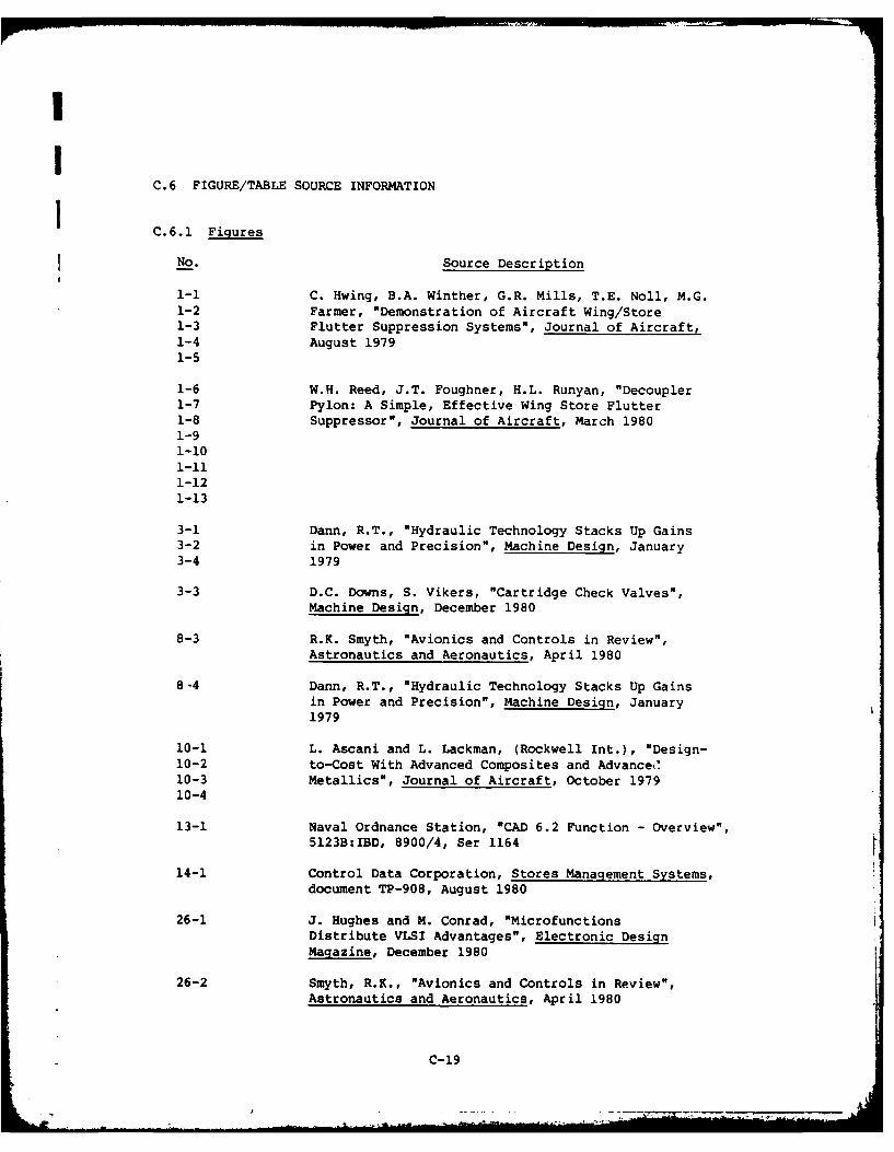
II
C.6 FIGURE/TABLE SOURCE INFORMATION
C.6.1 Figures
No. Source Description
1-1 C. Hwing, B.A. Winther, G.R. Mills, T.E. Noll, M.G.1-2 Farmer, "Demonstration of Aircraft Wing/Store1-3 Flutter Suppression Systems", Journal of Aircraft,1-4 August 19791-5
1-6 W.H. Reed, J.T. Foughner, H.L. Runyan, "Decoupler1-7 Pylon: A Simple, Effective Wing Store Flutter1-8 Suppressor", Journal of Aircraft, March 19801-91-101-111-121-13
3-1 Dann, R.T., "Hydraulic Technology Stacks Up Gains3-2 in Power and Precision", Machine Design, January3-4 1979
3-3 D.C. Downs, S. Vikers, "Cartridge Check Valves",Machine Design, December 1980
8-3 R.K. Smyth, "Avionics and Controls in Review",Astronautics and Aeronautics, April 1980
8-4 Dann, R.T., "Hydraulic Technology Stacks Up Gainsin Power and Precision", Machine Design, January1979
10-1 L. Ascani and L. Lackman, (Rockwell Int.), "Design-10-2 to-Cost With Advanced Composites and Advanced!10-3 Metallics", Journal of Aircraft, October 197910-4
13-1 Naval Ordnance Station, "CAD 6.2 Function - Overview",5123B:IBD, 8900/4, Ser 1164
14-1 Control Data Corporation, Stores Management Systems,document TP-908, August 1980
26-1 J. Hughes and M. Conrad, "MicrofunctionsDistribute VLSI Advantages", Electronic DesignMagazine, December 1980
26-2 Smyth, R.K., "Avionics and Controls in Review",Astronautics and Aeronautics, April 1980
C-19

No. Source Description
26-3 J. Hughes, "Micro-Computers - Technology isChanging the Issues", Digital Equipment Corp.
28-1 R.A. Juergens (McDonnell Aircraft Co.), "F/A-18
Hornet Display System", NAECON 1979, Vol. I(IEEE)
28-2 P.R. Snow (Mc Donnell Aircraft Co.), "F/A-18Horizontal Situation Display", NAECON 1980,Vol. 3 (IEEE)
29-1 W.J. Sternberg (Delco Electronics Div.,General Motors Corp.), "Stores Management andData Bus Systems", NAECON 1977 (IEEE)
29-2 L. Ciasulli, P. Henderson, "ULAIDS - 1553Architecture with Dynamic Bus Allocation",publication ASD-TR-78-34, October 1978,Aeronautical Systems Division
29-3 ILC Data Device Corp., "Specification BUS-1553,MIL-STD-1553 Interface Module", December 1980
30-1 M. Grossman, "Focus on Switching Power Supplies",Electronic Design Magazine, March 1981
31-1 J. McDermott, "EMI Shielding and ProtectiveComponents", EDN, September 5, 1979
31-2 Design Handbooks Branch, Aeronautical SystemsDivision, Design Handbook - Electromagnetic
Compatibility, Report AFSC DH 1-4, 10 January1969
32-1 C.K. Kao (ITT, Electro-Optical Products Division),"Future of Optical Fiber Systems for UnderseaApplications", Sea Technology Magazine, May 1980
34-1 J.M.H. Heines (Raytheon Co., Submarine Signal34-2 Division), "Built-in-Test and VHSIC/VLSI34-3 Technology", Electronics Test Magazine, October34-5 1980
34-4 R.K. Smyth (Milco International, Inc.), "Avionics
and Controls in Review", Astronautics andAeronautics, 1980
C-20
A

INo. Source Description
36-1 D. Bursky, "1981 Technology Forecast, DigitalLSI - Semiconductors", Electronic Design Magazine
36-2 E.R. Hnatek (Monolithic Memories), "Semiconductor36-3 Memory Update - Part 1: ROMS", Computer Design
Magazine, December 1979
37-1 D.M. Reece (Naval Weapons Support Center) and37-4 R.H. Huss (Naval Avionics Center), "The Standard
Electronic Modules Program", Electronic Packagingand Production Magazine, July 1980 (IEEE)
37-2 C.L. Lasses, "Wanted: A New Interconnection37-3 Technology", Electronics Magazine, September 27, 1979
39-1 J. Murray and J. Reising, "Tailoring Software Logicto the Needs of the Pilot: A Software Designer'sNightmare?", NAECON 1980, Vol. 3 (IEEE)
40-1 B.H. Carlisle, "Bipolars Fight Back", Machine Design40-2 Magazine, January 24, 198040-3
41-1 C.K. Kao (ITT, Electro-Optical Products Division),"Future of Optical Fiber Systems for Undersea
Applications", Sea Technology Magazine, May 1980
41-2 R.B. Laver, J. Schlafer, "LEDs or DSs: Which lightsource shines brightest in fiber-optic telecomsystems?", Electronic Design Magazine, April 12, 1980
C.6.2 Tables
No. Source Description
1-1 W.H. Reed, J.T. Foughner, H.L. Runyan, "DecouplerPylon: A Simple, Effe-tive Wing Store FlutterSuppressor", Journal of Aircraft, March 1980
3-1 Fairchild Stratos Division, "Space Shuttle Payloads"
10-1 W.A. Stauffer and J.H. Wooley (Lockhead-California10-2 Co.), "Future Trends in Aircraft Structural
Materials", Interavia S.A., March 1979
28-1 J.J. Hatsfield, J.B. Robertson, V.M. Batson28-3 (NASA/Langley Research Center), "Advanced Crew28-4 Station Concepts, Displays, and Input/Output
Technology for the Future", publication CH1518-0/79/0000/0187, IEEE
C-21
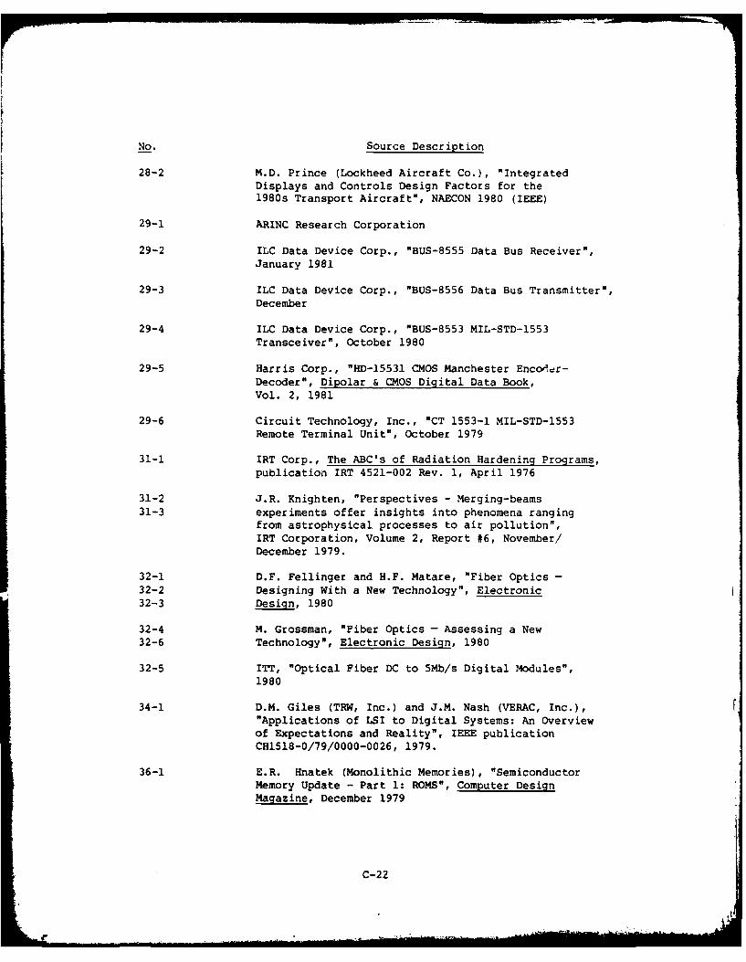
No. Source Description
28-2 M.D. Prince (Lockheed Aircraft Co.), "IntegratedDisplays and Controls Design Factors for the1980s Transport Aircraft", NAECON 1980 (IEEE)
29-1 ARINC Research Corporation
29-2 ILC Data Device Corp., "BUS-8555 Data Bus Receiver",
January 1981
29-3 ILC Data Device Corp., "BUS-8556 Data Bus Transmitter",December
29-4 ILC Data Device Corp., "BUS-8553 MIL-STD-1553Transceiver", October 1980
29-5 Harris Corp., "HD-15531 CMOS Manchester Encolder-Decoder", Dipolar & CMOS Digital Data Book,Vol. 2, 1981
29-6 Circuit Technology, Inc., "CT 1553-1 MIL-STD-1553
Remote Terminal Unit", October 1979
31-1 IRT Corp., The ABC's of Radiation Hardening Programs,
publication IRT 4521-002 Rev. 1, April 1976
31-2 J.R. Knighten, "Perspectives - Merging-beams
31-3 experiments offer insights into phenomena ranging
from astrophysical processes to air pollution",
IRT Corporation, Volume 2, Report #6, November!December 1979.
32-1 D.F. Fellinger and H.F. Matare, "Fiber Optics -32-2 Designing With a New Technology", Electronic32-3 Design, 1980
32-4 M. Grossman, "Fiber Optics - Assessing a New32-6 Technology", Electronic Design, 1980
32-5 ITT, "Optical Fiber DC to 5Mb/s Digital Modules",
1980
34-1 D.M. Giles (TRW, Inc.) and J.M. Nash (VERAC, Inc.),"Applications of LSI to Digital Systems: An Overviewof Expectations and Reality", IEEE publicationCH1518-0/79/0000-0026, 1979.
36-1 E.R. Hnatek (Monolithic Memories), "SemiconductorMemory Update - Part 1: ROMS", Computer DesignMagazine, December 1979
C-22
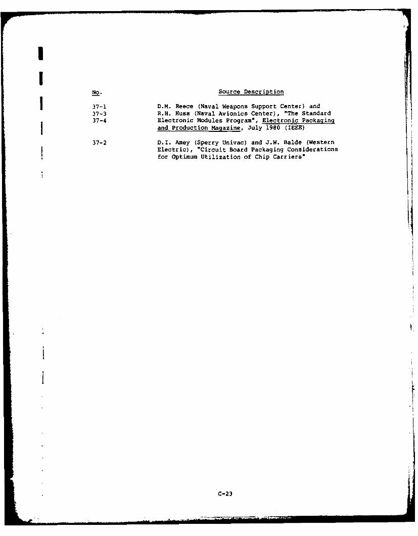
INo. Source Description
37-1 D.M. Reece (Naval Weapons Support Center) and37-3 R.H. Huss (Naval Avionics Center), "The Standard37-4 Electronic Modules Program", Electronic Packagingfand Production Magazine, July 1980 (IEEE)
37-2 D.I. Amey (Sperry Univac) and J.W. Balde (WesternElectric), "Circuit Board Packaging Considerationsfor Optimum Utilization of Chip Carriers"
I
C-2