Mcset User Manual
46
MCset 1-2-3 Medium Voltage Switchgear Withdrawable circuit breaker 17.5 kV User manual MCset
Transcript of Mcset User Manual
MCset 1-2-3Medium Voltage SwitchgearWithdrawable circuit breaker17.5 kV
User manual
MCset
07897302EN indice: C0 - 1
General 2Glossary 2Symbols 2Recommendations 3Standard tightening torques 3
General description 4Warning for readers 4AD cubicle 4TT1, TT2 cubicles 5CL-GL cubicles 5RHB, RHC cubicles 6Withdrawable mobile part 6Identification 9Read the inscriptions on the front panel 9
Instructions for access to the inside of a cubicle 11AD cubicle 11Removing front protection cover plates 12Removing the MV compartment separation sheet 13Removing the manhole sheet 14Removing and inserting fixed or withdrawable VTs 14Access to lower compartment (cables, CT, earthing switch, surge arresters) 15Accessing busbars 15Accessing plug-in pins 16
Installation and operation recommendation 17
Steps for the tests 18Voltage presence on MV cables 18MV cable tests 18
Operating Instructions 20Extracting or inserting the mobile part 20Plugging in the mobile part 24Withdrawing the mobile part 25Closing the earthing switch 26Opening the earthing switch 28Plugging in VT fuses 30Withdrawing VT fuses 31Padlocking and preventing access using padlocks 32Locking using locks (option) 34Locking using an electromagnet (option) 35
Corrective maintenance 36Forward 36Summary table 36Replacement of VT compartment fuses 37Replacing of a voltage indicator box 40Replacing the fans on 3600 A/ 4000 A cubicles 41Replacing the capacitor 41Putting back the new capacitor 42
Contents
Schneider Electric
2 - 07897302EN indice: C0
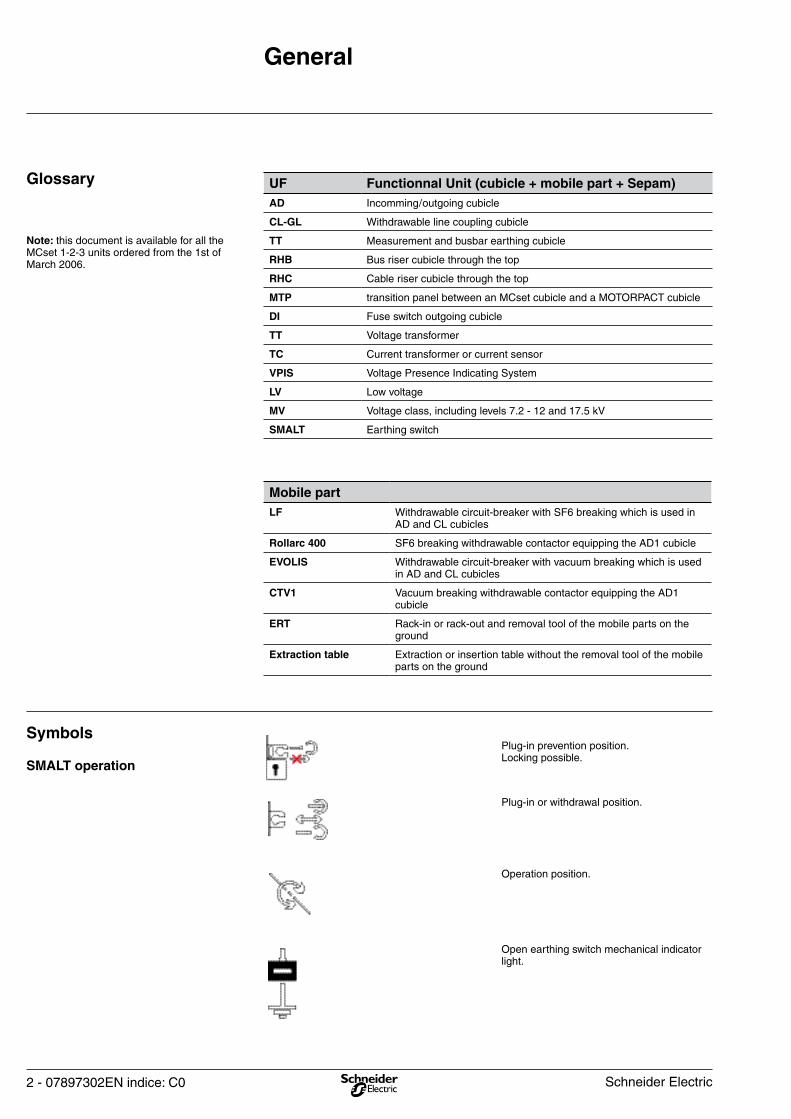
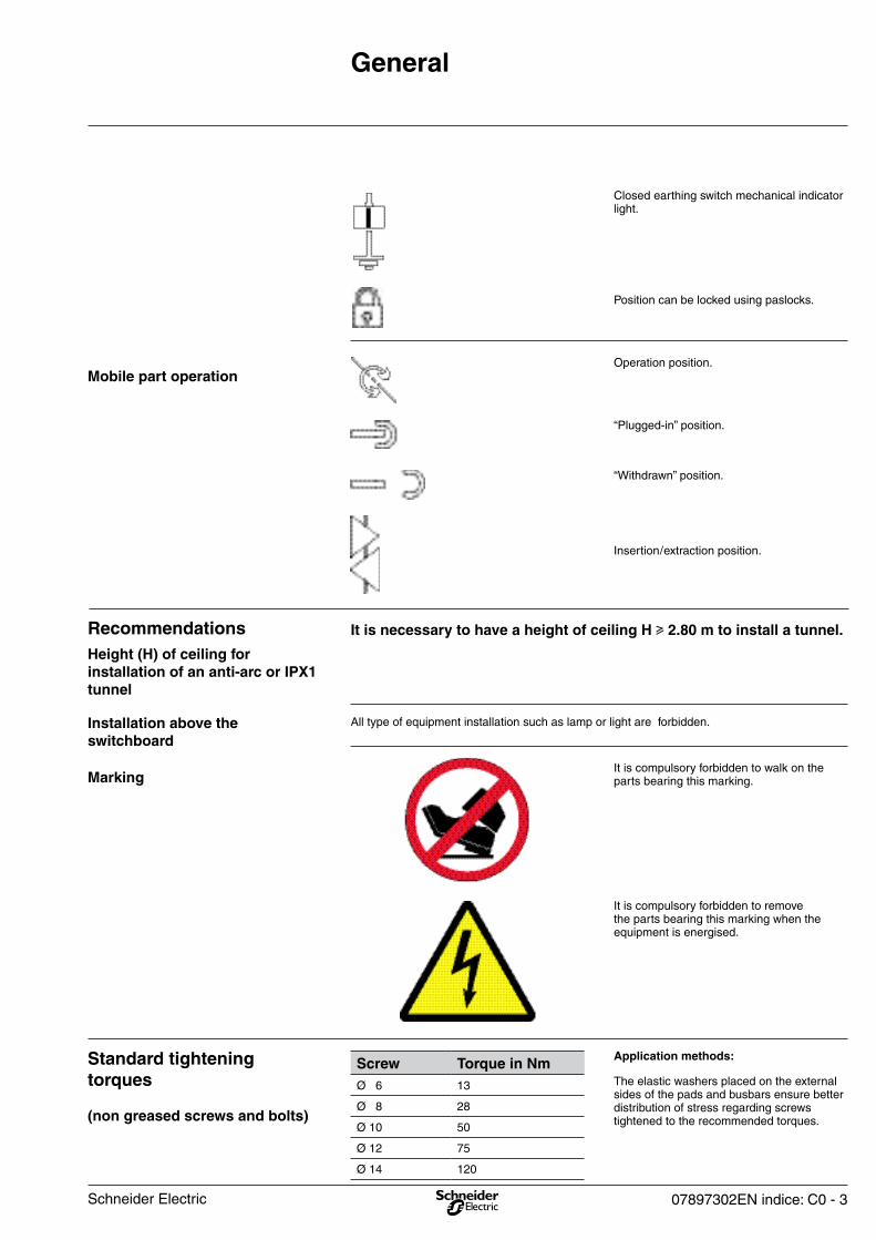
Open earthing switch mechanical indicator light.
Operation position.
Plug-in or withdrawal position.
Plug-in prevention position. Locking possible.
SMALT operation
Symbols
Mobile partLF Withdrawable circuit-breaker with SF6 breaking which is used in
AD and CL cubicles
Rollarc 400 SF6 breaking withdrawable contactor equipping the AD1 cubicle
EVOLIS Withdrawable circuit-breaker with vacuum breaking which is used in AD and CL cubicles
CTV1 Vacuum breaking withdrawable contactor equipping the AD1 cubicle
ERT Rack-in or rack-out and removal tool of the mobile parts on the ground
Extraction table Extraction or insertion table without the removal tool of the mobile parts on the ground
UF Functionnal Unit (cubicle + mobile part + Sepam)AD Incomming / outgoing cubicle
CL-GL Withdrawable line coupling cubicle
TT Measurement and busbar earthing cubicle
RHB Bus riser cubicle through the top
RHC Cable riser cubicle through the top
MTP transition panel between an MCset cubicle and a MOTORPACT cubicle
DI Fuse switch outgoing cubicle
TT Voltage transformer
TC Current transformer or current sensor
VPIS Voltage Presence Indicating System
LV Low voltage
MV Voltage class, including levels 7.2 - 12 and 17.5 kV
SMALT Earthing switch
Note: this document is available for all the MCset 1-2-3 units ordered from the 1st of March 2006.
Glossary
General
Schneider Electric
07897302EN indice: C0 - 3
It is compulsory forbidden to remove the parts bearing this marking when the equipment is energised.
It is compulsory forbidden to walk on the parts bearing this marking.Marking
All type of equipment installation such as lamp or light are forbidden.Installation above the switchboard
It is necessary to have a height of ceiling H u 2.80 m to install a tunnel.
Height (H) of ceiling for installation of an anti-arc or IPX1 tunnel
Recommendations
Insertion / extraction position.
“Withdrawn” position.
“Plugged-in” position.
Operation position.Mobile part operation
Position can be locked using paslocks.
Closed earthing switch mechanical indicator light.
General
The elastic washers placed on the external sides of the pads and busbars ensure better distribution of stress regarding screws tightened to the recommended torques.
Application methods:Screw Torque in NmØ 6 13
Ø 8 28
Ø 10 50
Ø 12 75
Ø 14 120
(non greased screws and bolts)
Standard tightening torques
Schneider Electric
4 - 07897302EN indice: C0
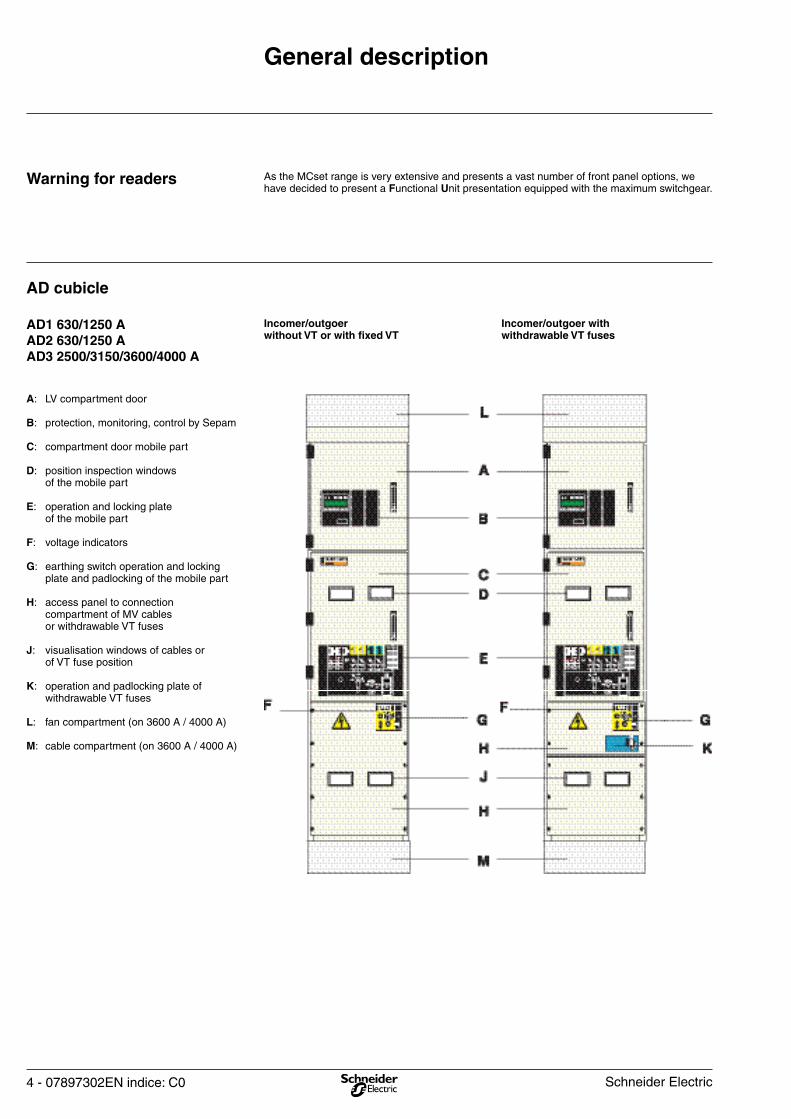
Incomer/outgoer with withdrawable VT fuses
Incomer/outgoer without VT or with fixed VT
A: LV compartment door B: protection, monitoring, control by Sepam C: compartment door mobile part D: position inspection windows of the mobile part E: operation and locking plate of the mobile part F: voltage indicators G: earthing switch operation and locking plate and padlocking of the mobile part H: access panel to connection compartment of MV cables or withdrawable VT fuses J: visualisation windows of cables or of VT fuse position K: operation and padlocking plate of withdrawable VT fuses
L: fan compartment (on 3600 A / 4000 A) M: cable compartment (on 3600 A / 4000 A)
AD1 630/1250 AAD2 630/1250 AAD3 2500/3150/3600/4000 A
AD cubicle
As the MCset range is very extensive and presents a vast number of front panel options, we have decided to present a Functional Unit presentation equipped with the maximum switchgear.
Warning for readers
General description
Schneider Electric
07897302EN indice: C0 - 5
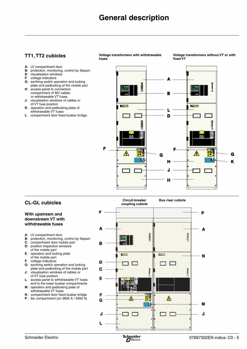
Bus riser cubicleCircuit-breakercoupling cubicle
A: LV compartment door B: protection, monitoring, control by Sepam C: compartment door mobile part D: position inspection windows of the mobile part E: operation and locking plate of the mobile part F: voltage indicators G: earthing switch operation and locking plate and padlocking of the mobile part J: visualisation windows of cables or of VT fuse positionL: access panel to withdrawable VT fuses and to the lower busbar compartments M : operation and padlocking plate of withdrawable VT fuses N : compartment door fixed busbar bridgeP : fan compartment (on 3600 A / 4000 A)
With upstream and downstream VT with withdrawable fuses
CL-GL cubicles
Voltage transformers without VT or with fixed VT
Voltage transformers with withdrawable fuses
TT1, TT2 cubicles
A: LV compartment door B: protection, monitoring, control by Sepam D: visualisation windows F: voltage indicators G: earthing switch operation and locking plate and padlocking of the mobile part H: access panel to connection compartment of MV cables or withdrawable VT fuses J: visualisation windows of cables or of VT fuse position K: operation and padlocking plate of withdrawable VT fusesL: compartment door fixed busbar bridge.
General description
Schneider Electric
6 - 07897302EN indice: C0
General description
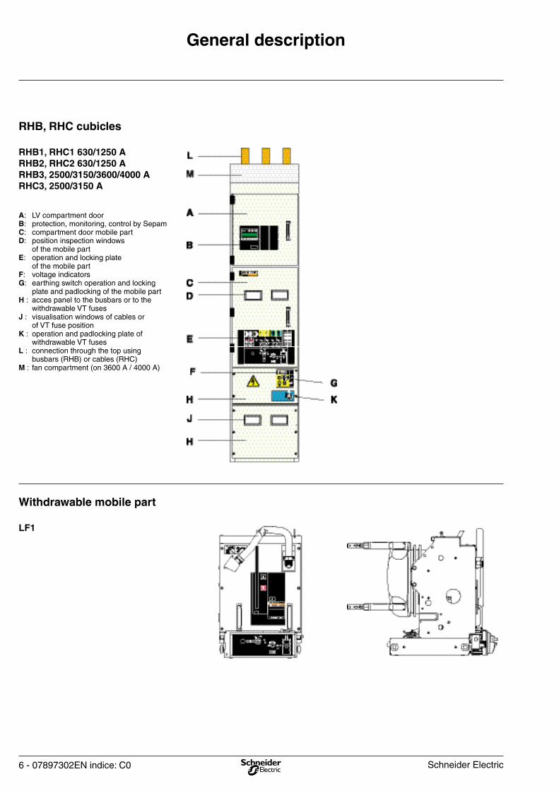
Withdrawable mobile part
A: LV compartment door B: protection, monitoring, control by Sepam C: compartment door mobile part D: position inspection windows of the mobile part E: operation and locking plate of the mobile part F: voltage indicators G: earthing switch operation and locking plate and padlocking of the mobile part H : acces panel to the busbars or to the withdrawable VT fusesJ : visualisation windows of cables or of VT fuse position K : operation and padlocking plate of withdrawable VT fusesL : connection through the top using busbars (RHB) or cables (RHC)M : fan compartment (on 3600 A / 4000 A)
RHB1, RHC1 630/1250 A RHB2, RHC2 630/1250 ARHB3, 2500/3150/3600/4000 ARHC3, 2500/3150 A
RHB, RHC cubicles
LF1
Schneider Electric
07897302EN indice: C0 - 7
General description
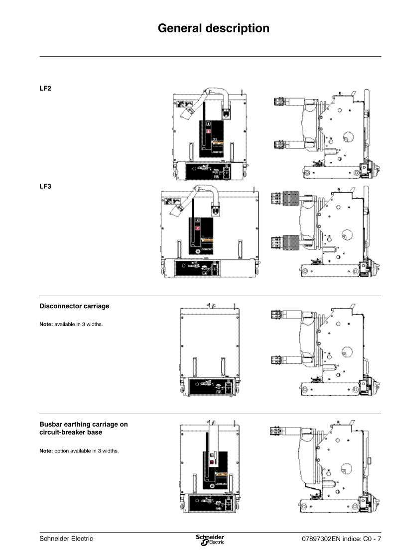
Note: option available in 3 widths.
Busbar earthing carriage on circuit-breaker base
Note: available in 3 widths.
Disconnector carriage
LF2
LF3
Schneider Electric
8 - 07897302EN indice: C0
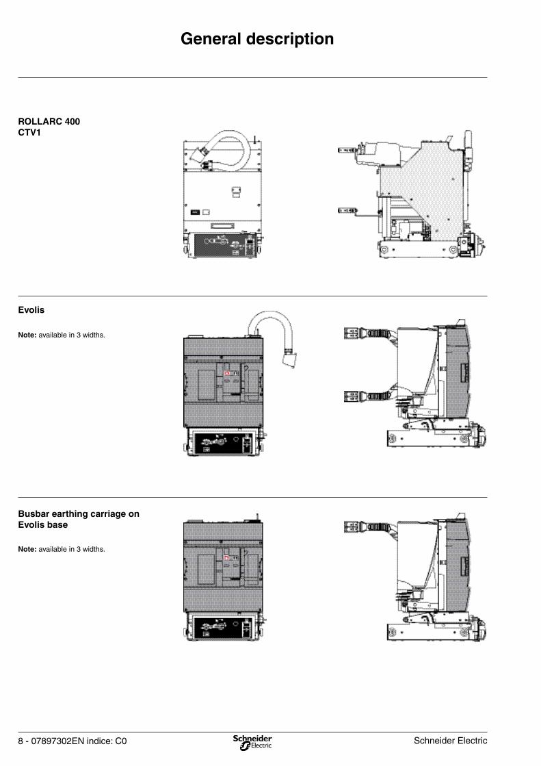
General description
ROLLARC 400CTV1
Note: available in 3 widths.
Evolis
Note: available in 3 widths.
Busbar earthing carriage on Evolis base
Schneider Electric
07897302EN indice: C0 - 9
General description
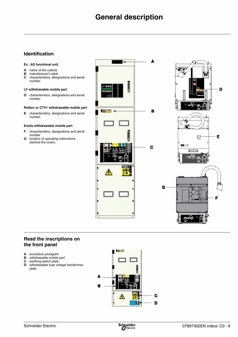
A: procedure pictogramB: withdrawable mobile partC: earthing switch plateD: withdrawable fuse voltage transformer plate.
Read the inscriptions on the front panel
F: characteristics, designations and serial numberG: location of operating instructions (behind the cover).
Evolis withdrawable mobile part
E: characteristics, designations and serial number.
Rollarc or CTV1 withdrawable mobile part
D: characteristics, designations and serial number.
LF withdrawable mobile part
A: name of the cubicleB: manufacturer’s labelC: characteristics, designations and serial number.
Ex : AD functional unit
Identification
Schneider Electric

10 - 07897302EN indice: C0
4 : earthing switch position selector5 : opening for the insertion of the earthing switch operating handleG : voltage presence H : plug-in prevention selector switchL : mechanical indicator of earthing switch statusM : location for plug-in prevention lockN : location for earthing switch locks.
Earthing switch, voltage presence and plug-in prevention
Cubicle
1: mechanical opening push-button2: mobile part position selector 3: opening for inserting mobile part operating handle E: mechanical indicator light for indication of the mobile part positionF: location for disconnector carriage lock (optional).
Mobile part
1: mobile part operation2: earthing switch operation.
Procedure pictogram
6 : position selector switch for voltage transformer withdrawable fuses7 : opening for the insertion of the voltage transformer withdrawable fuse operating handle.
Withdrawable voltage transformer
General description
Schneider Electric
07897302EN indice: C0 - 11
Instructions for access to the inside of a cubicle
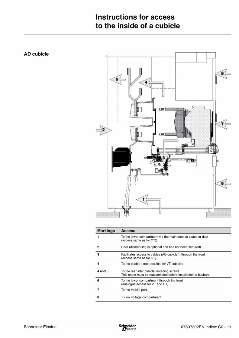
AD cubicle
Markings Access1 To the lower compartment via the maintenance space or duct
(access same as for CT)).
2 Rear (dismantling is optional and has not been secured).
3 Facilitates access to cables (AD cubicle ), through the front(access same as for CT).
4 To the busbars (not possible for VT cubicle).
4 and 5 To the rear inter cubicle fastening screws.This sheet must be reassembled before installation of busbars.
6 To the lower compartment through the front (analogue access for VT and CT).
7 To the mobile part.
8 To low voltage compartment.
Schneider Electric

12 - 07897302EN indice: C0
Instructions for access to the inside of a cubicle
Cubicle equipped with a withdrawable fusevoltage transformer
Cubicle with or without fixed voltage transformer (VT)
Removing front protection cover plates
It is recommended to padlock it in this position (see chapter “Padlocking and preventing access with padlocks”).
Close earthing switch (see chapter “Closing the earthing switch”).
Withdraw VT fuses (see chapter “Withdrawing VT fuses”).
In the case of a cubicle equipped with a fixed VT.
Close earthing switch (see chapter “Closing the earthing switch”).
It is recommended to padlock it in this position (see chapter “Padlocking and preventing access using padlocks”).
Dismantle the panel (10 screws).
To place back into operation, carry out operations in the reverse order of removal (closed earthing switch).
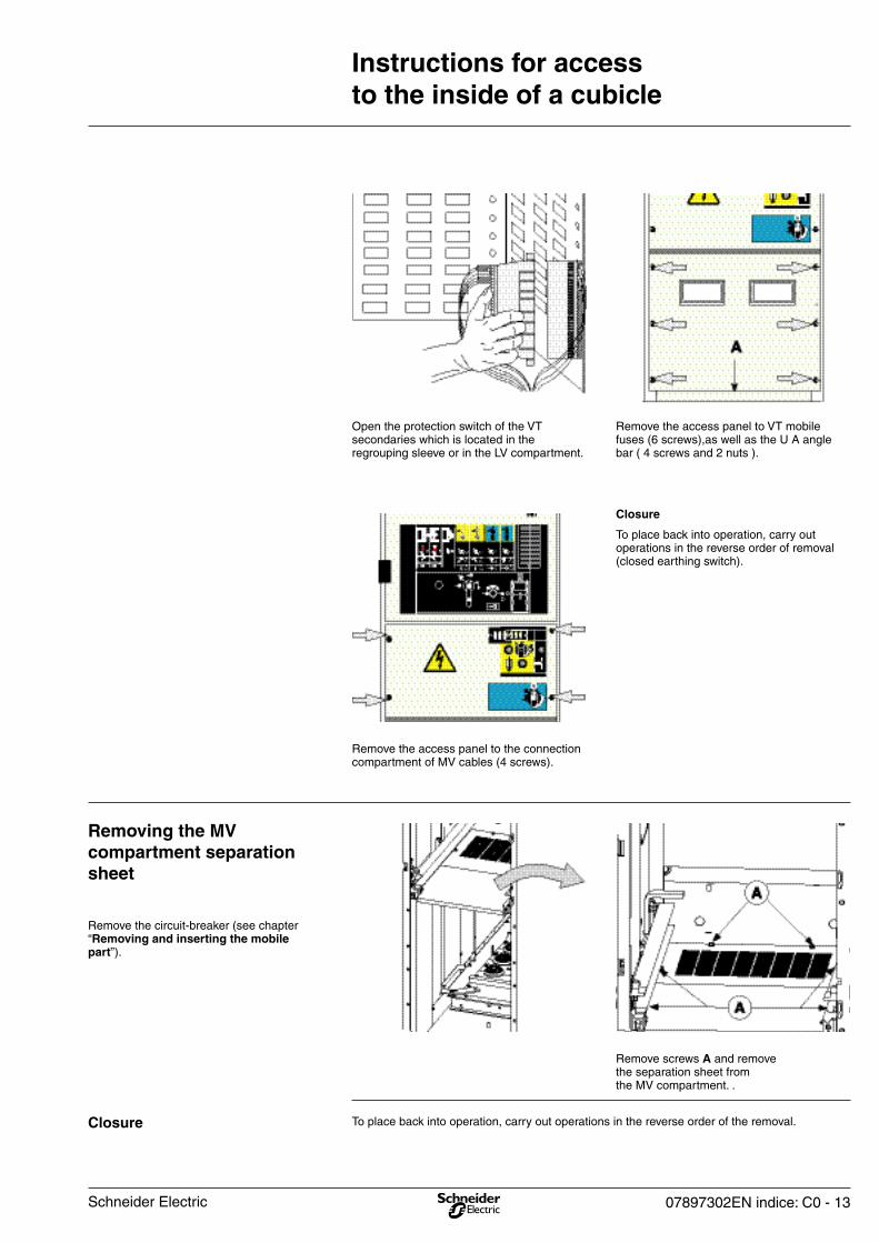
Closure
Open the protection switch of the VT secondaries which is located in the regrouping sleeve or in the LV compartment.
Schneider Electric
07897302EN indice: C0 - 13
Instructions for access to the inside of a cubicle
To place back into operation, carry out operations in the reverse order of the removal.Closure
Remove the circuit-breaker (see chapter “Removing and inserting the mobile part”).
Removing the MV compartment separation sheet
Remove the access panel to VT mobile fuses (6 screws),as well as the U A angle bar ( 4 screws and 2 nuts ).
Open the protection switch of the VT secondaries which is located in the regrouping sleeve or in the LV compartment.
Remove screws A and remove the separation sheet from the MV compartment. .
To place back into operation, carry out operations in the reverse order of removal (closed earthing switch).
Closure
Remove the access panel to the connection compartment of MV cables (4 screws).
Schneider Electric
14 - 07897302EN indice: C0
Instructions for access to the inside of a cubicle
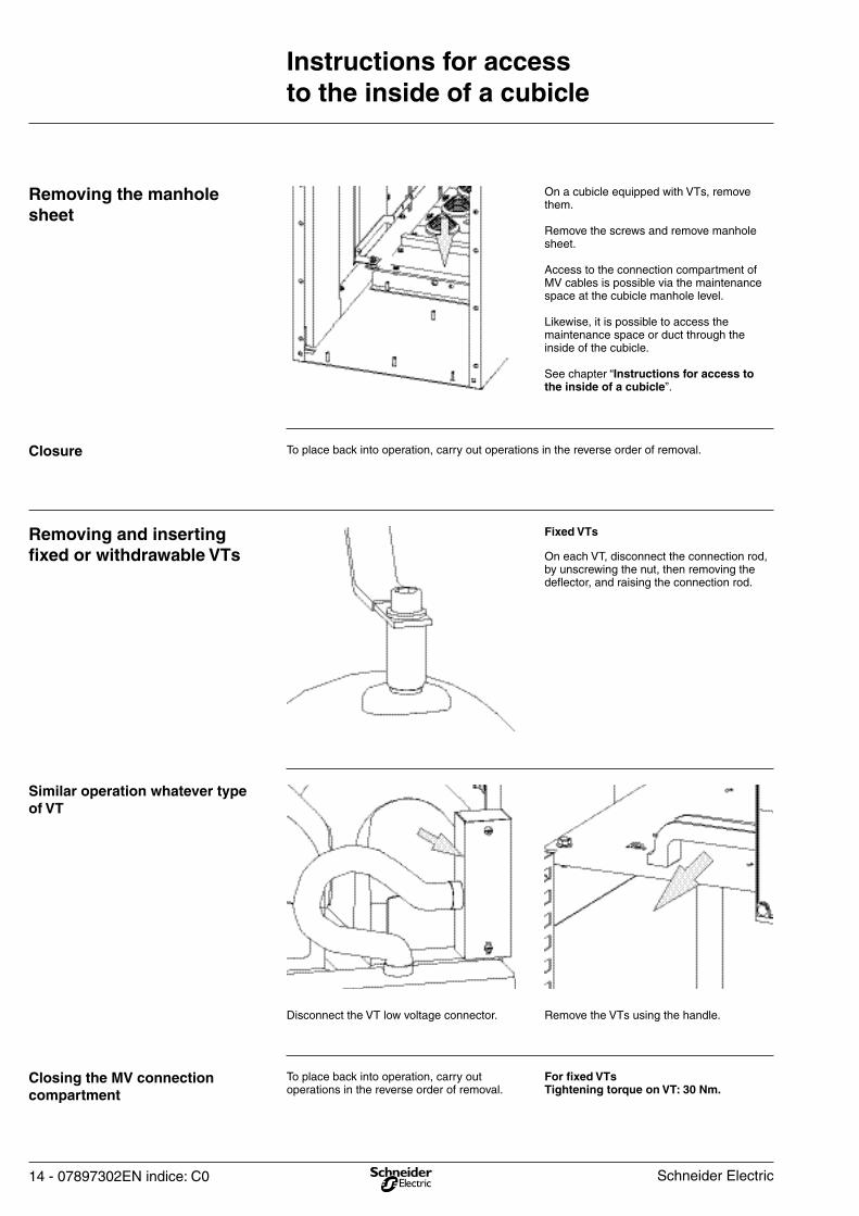
Closing the MV connection compartment
Similar operation whatever type of VT
Removing and inserting fixed or withdrawable VTs
Closure
Removing the manhole sheet
For fixed VTs Tightening torque on VT: 30 Nm.
To place back into operation, carry out operations in the reverse order of removal.
On each VT, disconnect the connection rod, by unscrewing the nut, then removing the deflector, and raising the connection rod.
To place back into operation, carry out operations in the reverse order of removal.
On a cubicle equipped with VTs, remove them.
Remove the screws and remove manhole sheet.
Access to the connection compartment of MV cables is possible via the maintenance space at the cubicle manhole level.
Likewise, it is possible to access the maintenance space or duct through the inside of the cubicle.
See chapter “Instructions for access to the inside of a cubicle”.
Fixed VTs
Remove the VTs using the handle.Disconnect the VT low voltage connector.
Schneider Electric
07897302EN indice: C0 - 15
Instructions for access to the inside of a cubicle
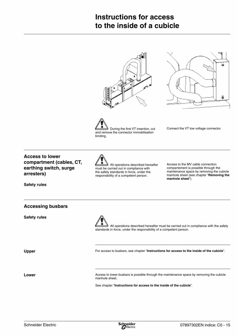
Access to lower busbars is possible through the maintenance space by removing the cubicle manhole sheet.
See chapter “Instructions for access to the inside of the cubicle”.
Lower
For access to busbars, see chapter “Instructions for access to the inside of the cubicle”.Upper
All operations described hereafter must be carried out in compliance with the safety standards in force, under the responsibility of a competent person.
Safety rules
Accessing busbars
All operations described hereafter must be carried out in compliance with the safety standards in force, under the responsibility of a competent person.
Safety rules
Access to lower compartment (cables, CT, earthing switch, surge arresters)
Connect the VT low voltage connector. During the first VT insertion, cut and remove the connector immobilisation binding.
Access to the MV cable connection compartement is possible through the maintenance space by removing the cubicle manhole sheet (see chapter “Removing the manhole sheet”).
Schneider Electric

16 - 07897302EN indice: C0
Instructions for access to the inside of a cubicle
Push the flaps upwards up to locking.To close, pull the flaps downwards up to locking.
Using a screwdriver, raise the vane to release the locking. Push the ball into the link axis.
Opening and closing upper flaps
The flaps fall downwards up to locking.To close, pull the flaps upwards up to locking.
Using a screwdriver, raise the vane to release the locking.Push the ball into the link axis.
Opening and closing lower flaps
All operations described hereafter must be carried out in compliance with the safety standards in force, under the responsibility of a competent person.
Safety rules
Accessing plug-in pins
Before re-plugging in the mobile part, ensure that the shutters mechanisms have been put back into their initial position (locked closed). Failure to comply with this instruction may result in damage to the equipment.
Schneider Electric
07897302EN indice: C0 - 17
Installation and operation recommendation
It is strongly advised to periodically carry out, (minimun every 2 years approximately), a few operation cycles on operating devices.
Outside normal conditions of use, (between -5°C and 40°C , absence of dust, corrosive gas, etc.), it is recommended to examine, with our Schneider Electric services centre, the steps to be taken, in order to ensure correct functioning of the installation.
After 6 to 12 month operations, we recommend you to check the busbars and MV cable connection tightening.It should be done with a calibrated torque spanner, adjust to lower torque compare to values indicated in page 4.
Operation and maintenance
The necessity of correct implementation of connections:
New cold retractable or slip-on technology offers ease of installation that favours resistance over time.
Their design allows them to used in polluted environments with harsh climatic conditions.
Impact of the relative humidity factor:
Installing a heating device is essential in climates with high relative humidity levels and major temperature differences.
Ensure that draughts and / or thermal shocks are avoided in all cubicle compartments in order to avoid the creation of dew points (sources of partial discharges).
the switchgear’s resistance to ageing in an MV substation depends on 3 main factors:
The equipment must be installed in conformity with the relevant IEC standard. Outside of these normal usage conditions, we recommend contacting Schneider Electric to determine the operations to be carried out as well as their frequency according to the actual service conditions.
Ventilation control:
Grid size must be suited to the power dissipated in the substation. These grids must be placed exclusively in the vicinity of the transformer, in order to avoid air circulation on the LV switchboard.
If no problems are detected and if the busbars and cable connections haven’t been modified, it will not necessary to do again this check. In case of dismantling, the elastic washers must be change and replace by new ones supplied by Schneider Electric.
Our service centre is at your disposal at any time:
- To undergo an installation diagnostic,
- To offer you, if need be, suitable maintenance operations,
- To offer you maintenance contracts,
- to offer you adaptations.
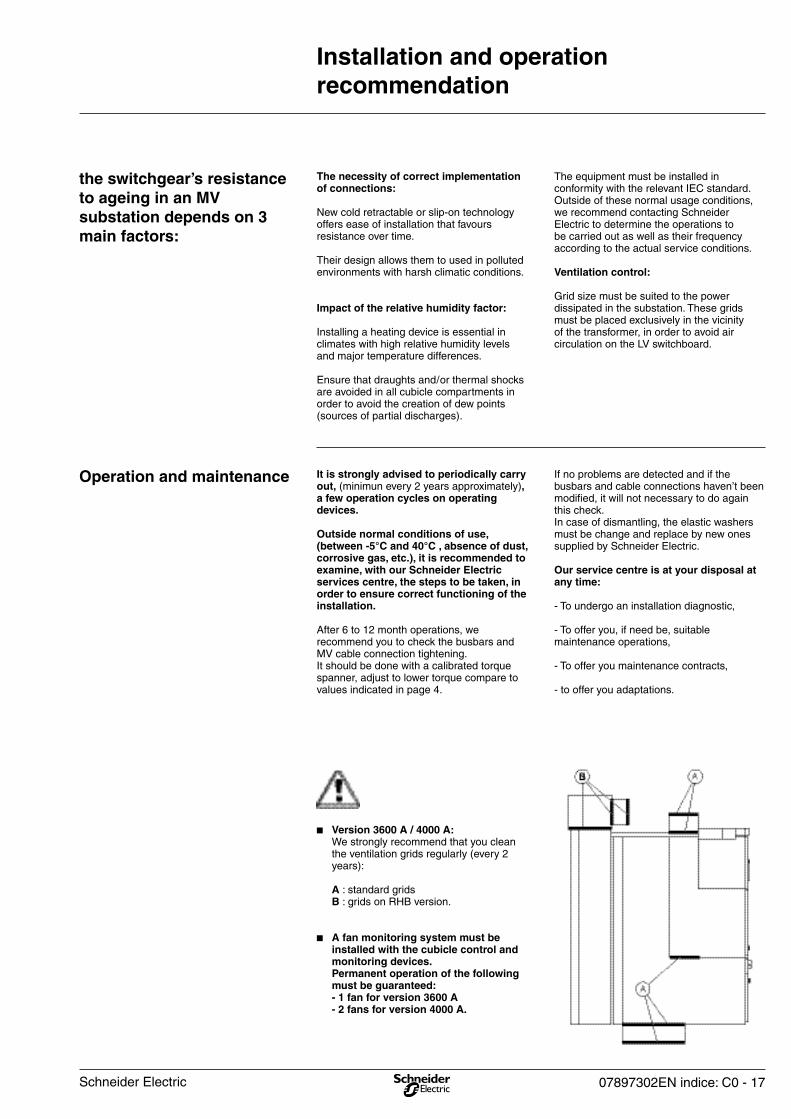
b Version 3600 A / 4000 A: We strongly recommend that you clean the ventilation grids regularly (every 2 years):
A : standard grids B : grids on RHB version.
b A fan monitoring system must be installed with the cubicle control and monitoring devices. Permanent operation of the following must be guaranteed: - 1 fan for version 3600 A - 2 fans for version 4000 A.
Schneider Electric
18 - 07897302EN indice: C0
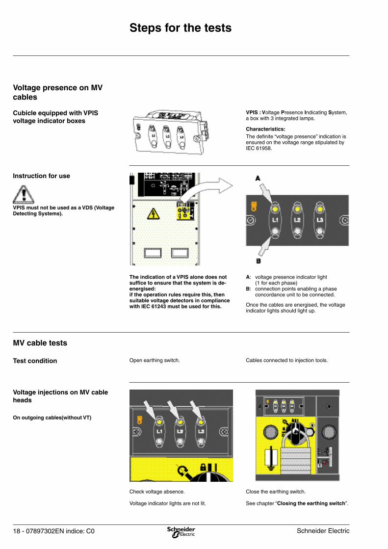
Close the earthing switch.
See chapter “Closing the earthing switch”.
Check voltage absence.
Voltage indicator lights are not lit.
On outgoing cables(without VT)
Voltage injections on MV cable heads
Cables connected to injection tools.Open earthing switch.Test condition
MV cable tests
Once the cables are energised, the voltage indicator lights should light up.
A: voltage presence indicator light (1 for each phase)B: connection points enabling a phase concordance unit to be connected.
The indication of a VPIS alone does not suffice to ensure that the system is de-energised: if the operation rules require this, then suitable voltage detectors in compliance with IEC 61243 must be used for this.
VPIS must not be used as a VDS (Voltage Detecting Systems).
Instruction for use
The definite “voltage presence” indication is ensured on the voltage range stipulated by IEC 61958.
Characteristics:
VPIS : Voltage Presence Indicating System, a box with 3 integrated lamps.
Cubicle equipped with VPIS voltage indicator boxes
Voltage presence on MV cables
Steps for the tests
Schneider Electric
07897302EN indice: C0 - 19
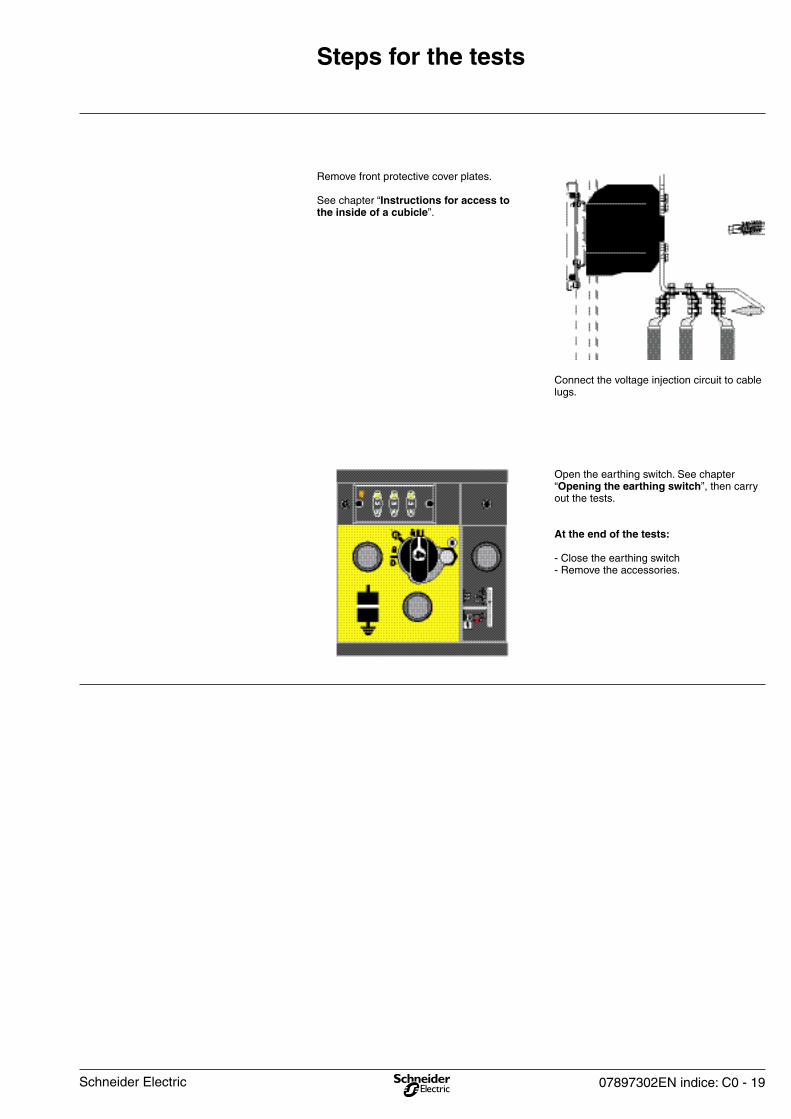
Open the earthing switch. See chapter “Opening the earthing switch”, then carry out the tests.
At the end of the tests:
- Close the earthing switch- Remove the accessories.
Connect the voltage injection circuit to cable lugs.
Remove front protective cover plates.
See chapter “Instructions for access to the inside of a cubicle”.
Steps for the tests
Schneider Electric
20 - 07897302EN indice: C0
Operating Instructions
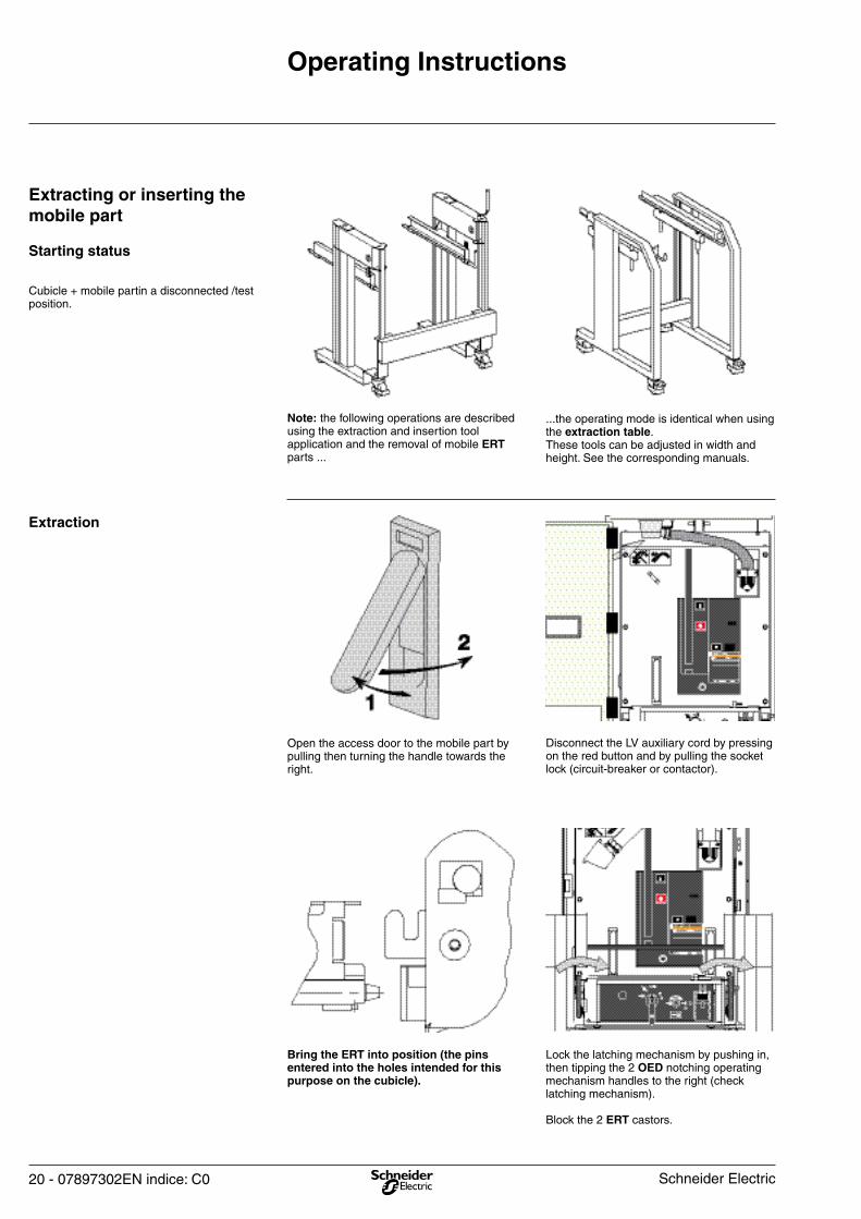
Lock the latching mechanism by pushing in, then tipping the 2 OED notching operating mechanism handles to the right (check latching mechanism).
Block the 2 ERT castors.
Bring the ERT into position (the pins entered into the holes intended for this purpose on the cubicle).
Disconnect the LV auxiliary cord by pressing on the red button and by pulling the socket lock (circuit-breaker or contactor).
Open the access door to the mobile part by pulling then turning the handle towards the right.
Extraction
...the operating mode is identical when using the extraction table.These tools can be adjusted in width and height. See the corresponding manuals.
Note: the following operations are described using the extraction and insertion tool application and the removal of mobile ERT parts ...
Cubicle + mobile partin a disconnected /test position.
Starting status
Extracting or inserting the mobile part
Schneider Electric
07897302EN indice: C0 - 21
Operating Instructions
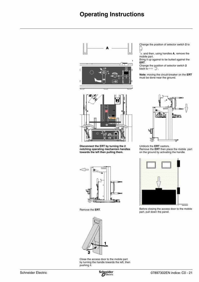
Close the access door to the mobile part by turning the handle towards the left, then pushing it.
Before closing the access door to the mobile part, pull down the panel.
Unblock the ERT castors.Remove the ERT then place the mobile part on the ground by activating the handle.
Disconnect the ERT by turning the 2 notching operating mechanism handles towards the left then pulling them.
Change the position of selector switch 2 to
and then, using handles A, remove the mobile part. Bring it up against to be butted against the ERT.Change the position of selector switch 2 back to .
Note: moving the circuit-breaker on the ERT must be done near the ground.
Remove the ERT.
Schneider Electric
22 - 07897302EN indice: C0
Operating Instructions
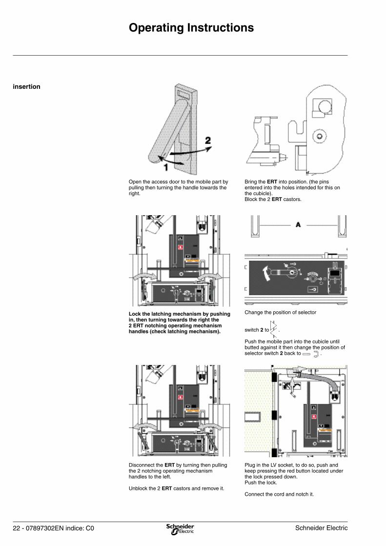
Plug in the LV socket, to do so, push and keep pressing the red button located under the lock pressed down. Push the lock.
Connect the cord and notch it.
Disconnect the ERT by turning then pulling the 2 notching operating mechanism handles to the left.
Unblock the 2 ERT castors and remove it.
Change the position of selector
switch 2 to . Push the mobile part into the cubicle until butted against it then change the position of selector switch 2 back to .
Lock the latching mechanism by pushing in, then turning towards the right the 2 ERT notching operating mechanism handles (check latching mechanism).
Bring the ERT into position. (the pins entered into the holes intended for this on the cubicle).Block the 2 ERT castors.
Open the access door to the mobile part by pulling then turning the handle towards the right.
insertion
Schneider Electric

07897302EN indice: C0 - 23
Operating Instructions
Close the access door to the mobile part by turning the handle to the left then pushing it.
Before closing the access door to the mobile part, lift the panel, and ensure that it is well notched at the top.
Schneider Electric

24 - 07897302EN indice: C0
Change the position of selector switch 2
to .
Insert the crank into opening 3.
Plug in the mobile part by turning the crank (45 turns) clockwise until the position indicator changes status.
Lower the protective flap of push-button 1.Press push-button 1, and while keeping it pushed down. Change the position of selector switch 2
to .
Operation
Door closed Selector switch 4 to (open earthing switch)
Selector switch H in plug-in or drawout position to
Starting status
Plugging in the mobile part
The pictogram with a black background on the front plate is a reminder of the operations.
In the case of a circuit-breaker or a contactor, the electric operation for charging the downstream part of installation is now possible.
Operating Instructions
Schneider Electric

07897302EN indice: C0 - 25
Operating Instructions
The mobile part is withdrawn.The cubicle is in the disconnected position.
Change the position of selector switch 2
to .
Insert the crank into opening 3. Withdraw the mobile part by turning the crank (45 turns) anti-clockwise until the position indicator changes status.
Press push-button 1 (which sends an order for the mechanical opening of the circuit-breaker).While keeping it pushed down, change the position of selector switch 2 to .
Operation
The mobile part in the plugged-in position.
Starting status
Withdrawing the mobile part
The pictogram with a black background on the front plate is a reminder of the operations.
Schneider Electric
26 - 07897302EN indice: C0
Operating Instructions
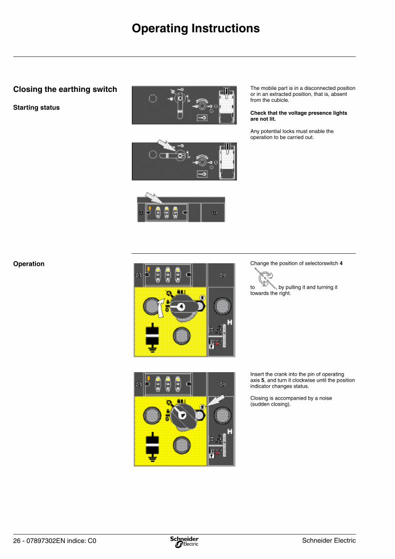
Insert the crank into the pin of operating axis 5, and turn it clockwise until the position indicator changes status.
Closing is accompanied by a noise (sudden closing).
Change the position of selectorswitch 4
to , by pulling it and turning it towards the right.
Operation
Any potential locks must enable the operation to be carried out.
Check that the voltage presence lights are not lit.
The mobile part is in a disconnected position or in an extracted position, that is, absent from the cubicle.
Starting status
Closing the earthing switch
Schneider Electric
07897302EN indice: C0 - 27
Operating Instructions
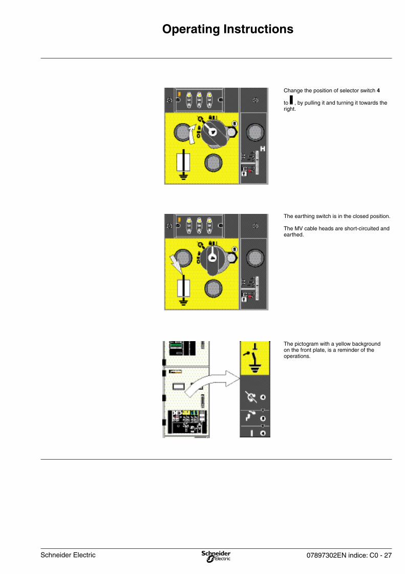
The pictogram with a yellow background on the front plate, is a reminder of the operations.
The earthing switch is in the closed position.
The MV cable heads are short-circuited and earthed.
Change the position of selector switch 4
to , by pulling it and turning it towards the right.
Schneider Electric
28 - 07897302EN indice: C0
Operating Instructions
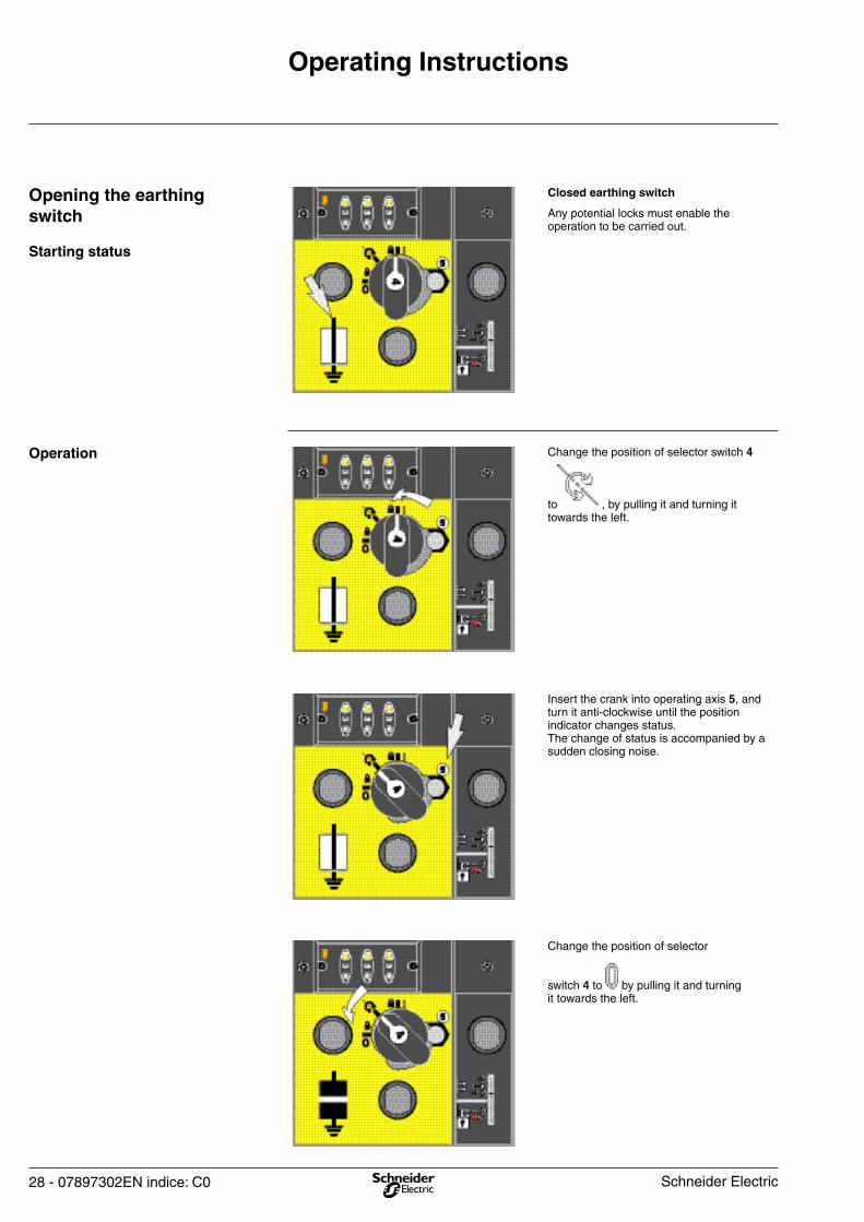
Any potential locks must enable the operation to be carried out.
Closed earthing switch
Starting status
Opening the earthing switch
Change the position of selector
switch 4 to by pulling it and turning it towards the left.
Insert the crank into operating axis 5, and turn it anti-clockwise until the position indicator changes status.The change of status is accompanied by a sudden closing noise.
Change the position of selector switch 4
to , by pulling it and turning it towards the left.
Operation
Schneider Electric
07897302EN indice: C0 - 29
Operating Instructions
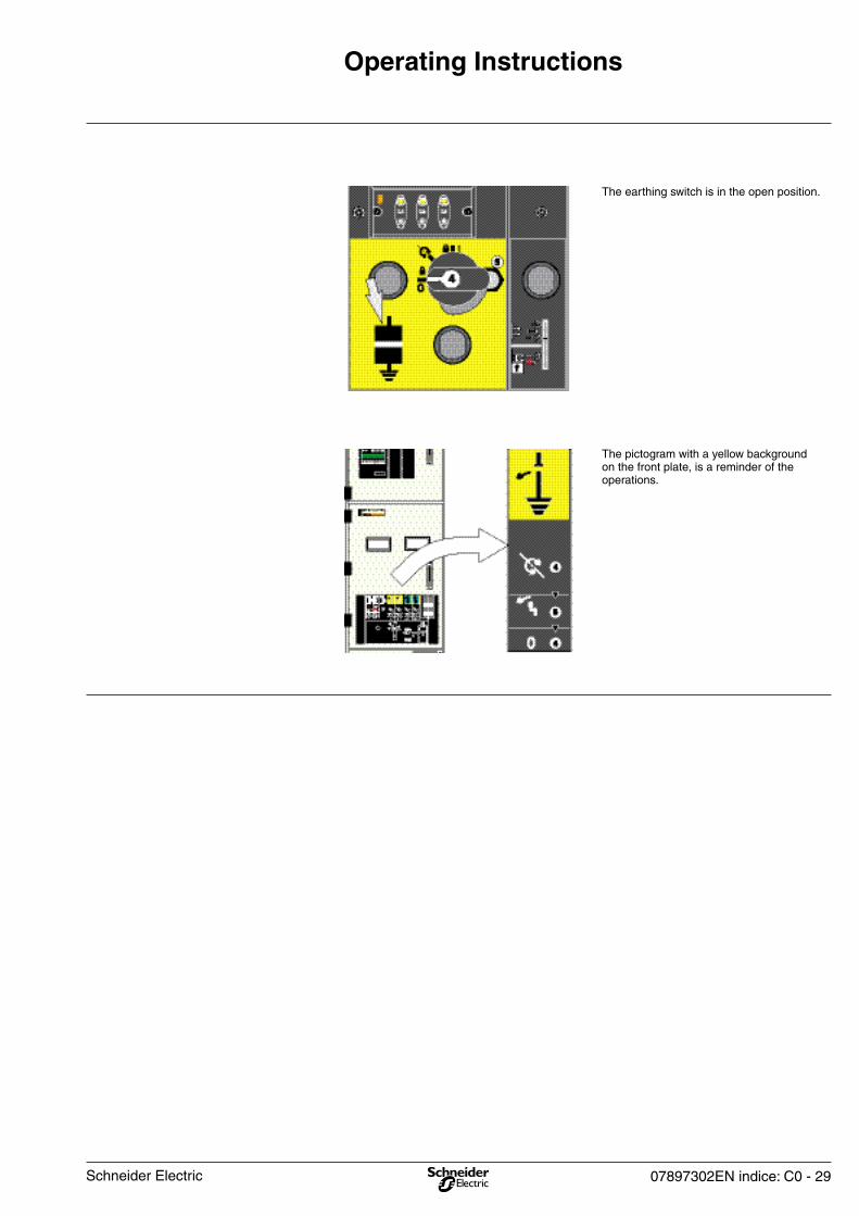
The earthing switch is in the open position.
The pictogram with a yellow background on the front plate, is a reminder of the operations.
Schneider Electric
30 - 07897302EN indice: C0
Operating Instructions
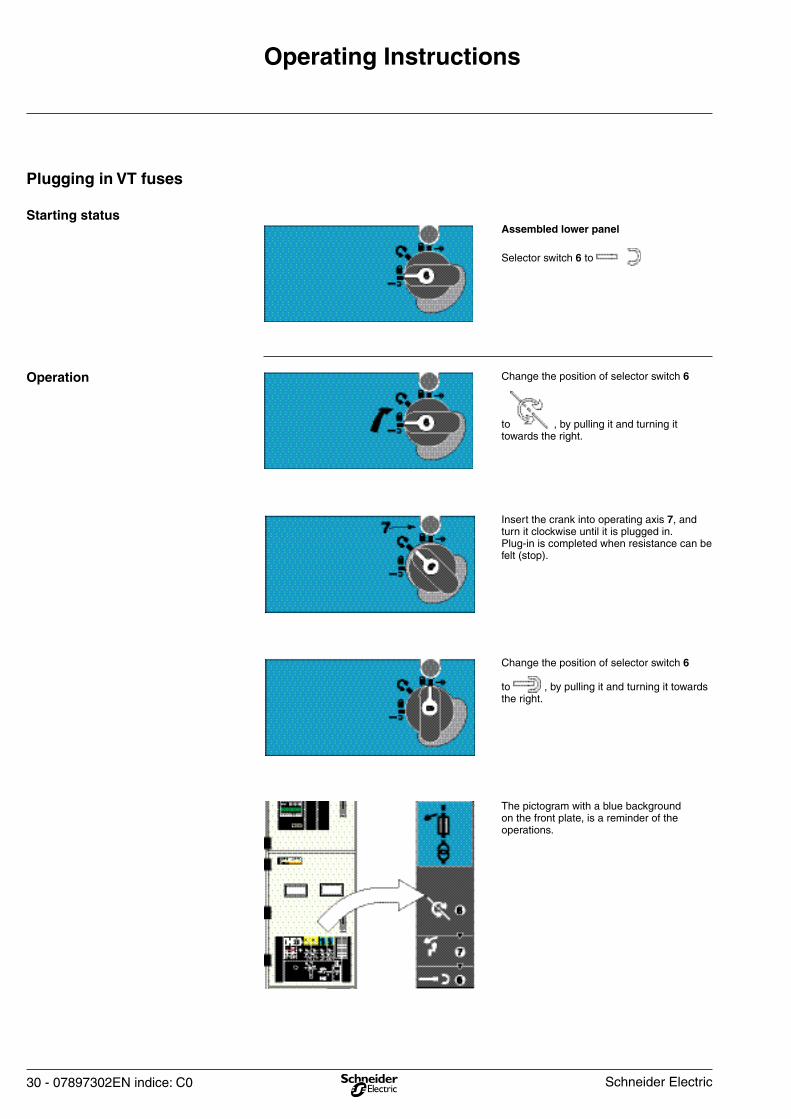
Change the position of selector switch 6
to , by pulling it and turning it towards the right.
Insert the crank into operating axis 7, and turn it clockwise until it is plugged in.Plug-in is completed when resistance can be felt (stop).
Change the position of selector switch 6
to , by pulling it and turning it towards the right.
Operation
Selector switch 6 to
Assembled lower panelStarting status
Plugging in VT fuses
The pictogram with a blue background on the front plate, is a reminder of the operations.
Schneider Electric
07897302EN indice: C0 - 31
Operating Instructions
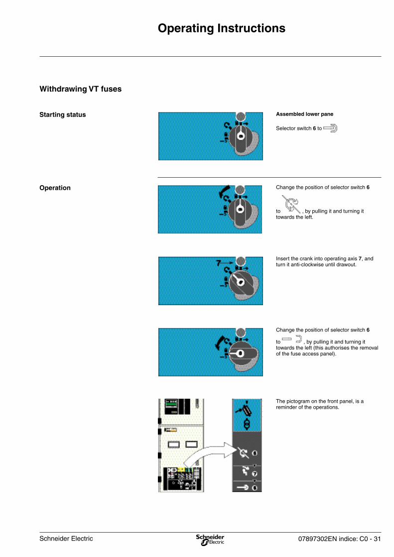
Change the position of selector switch 6
to , by pulling it and turning it towards the left (this authorises the removal of the fuse access panel).
Insert the crank into operating axis 7, and turn it anti-clockwise until drawout.
Change the position of selector switch 6
to , by pulling it and turning it towards the left.
Operation
Selector switch 6 to
Assembled lower paneStarting status
Withdrawing VT fuses
The pictogram on the front panel, is a reminder of the operations.
Schneider Electric
32 - 07897302EN indice: C0
Operating Instructions
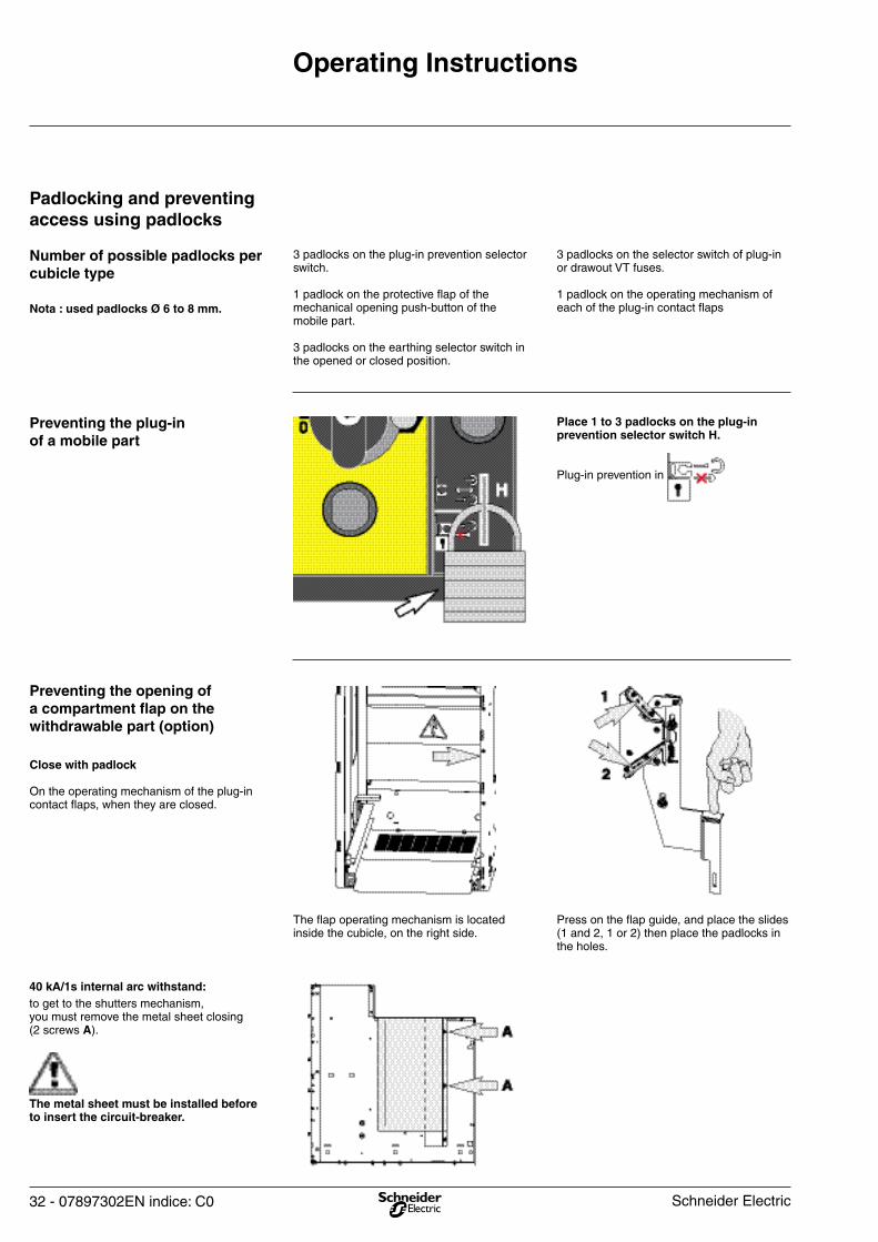
Press on the flap guide, and place the slides (1 and 2, 1 or 2) then place the padlocks in the holes.
The flap operating mechanism is located inside the cubicle, on the right side.
On the operating mechanism of the plug-in contact flaps, when they are closed.
Close with padlock
Preventing the opening of a compartment flap on the withdrawable part (option)
Place 1 to 3 padlocks on the plug-in prevention selector switch H.
Plug-in prevention in
Preventing the plug-in of a mobile part
3 padlocks on the selector switch of plug-in or drawout VT fuses.
1 padlock on the operating mechanism of each of the plug-in contact flaps
3 padlocks on the plug-in prevention selector switch.
1 padlock on the protective flap of the mechanical opening push-button of the mobile part.
3 padlocks on the earthing selector switch in the opened or closed position.
Nota : used padlocks Ø 6 to 8 mm.
Number of possible padlocks per cubicle type
Padlocking and preventing access using padlocks
The metal sheet must be installed before to insert the circuit-breaker.
to get to the shutters mechanism, you must remove the metal sheet closing(2 screws A).
40 kA/1s internal arc withstand:
Schneider Electric
07897302EN indice: C0 - 33
Operating Instructions
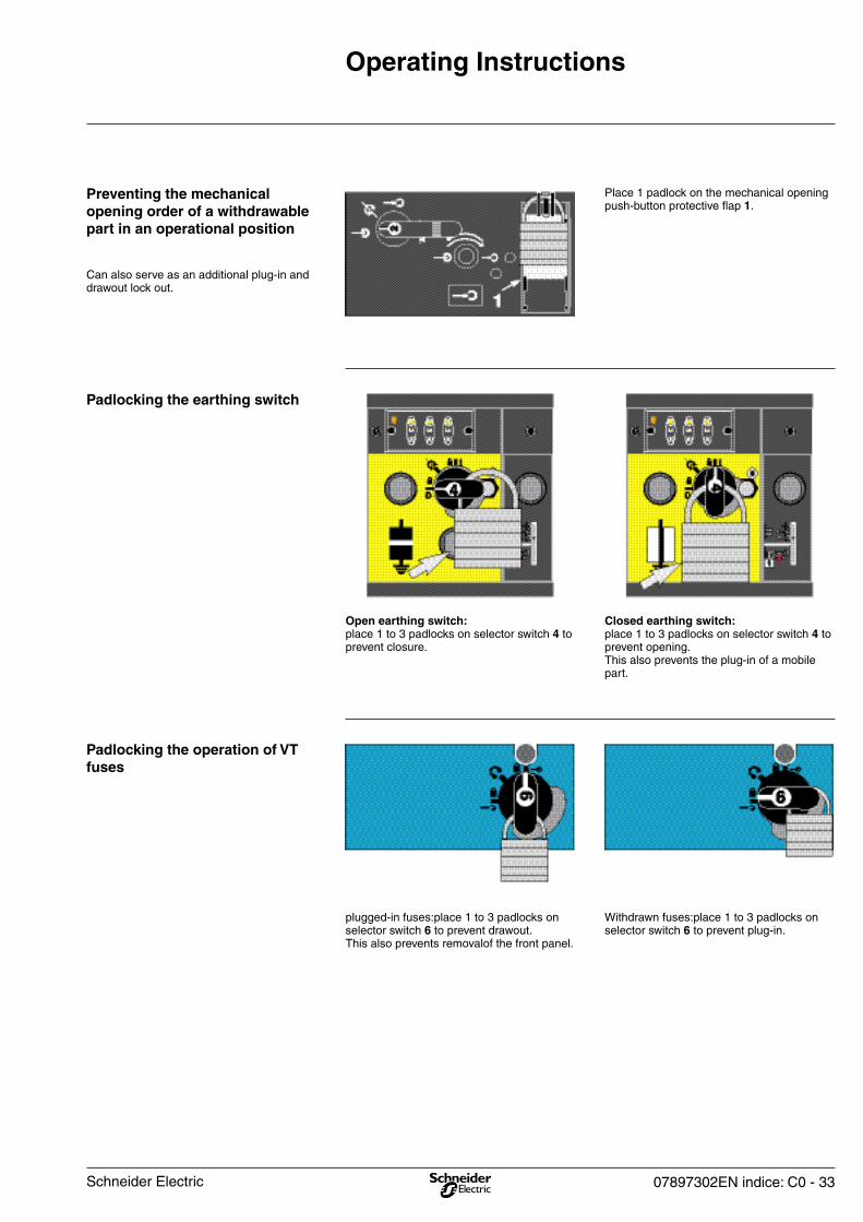
Withdrawn fuses:place 1 to 3 padlocks on selector switch 6 to prevent plug-in.
plugged-in fuses:place 1 to 3 padlocks on selector switch 6 to prevent drawout.This also prevents removalof the front panel.
Padlocking the operation of VT fuses
Closed earthing switch: place 1 to 3 padlocks on selector switch 4 to prevent opening.This also prevents the plug-in of a mobile part.
Open earthing switch: place 1 to 3 padlocks on selector switch 4 to prevent closure.
Padlocking the earthing switch
Place 1 padlock on the mechanical opening push-button protective flap 1.
Can also serve as an additional plug-in and drawout lock out.
Preventing the mechanical opening order of a withdrawable part in an operational position
Schneider Electric
34 - 07897302EN indice: C0
Operating Instructions
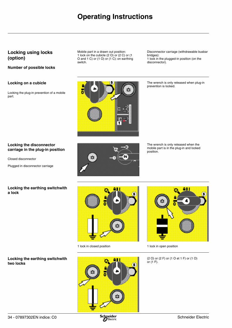
(2 O) or (2 F) or (1 O et 1 F) or (1 O) or (1 F).
Locking the earthing switchwith two locks
1 lock in open position1 lock in closed position
Locking the earthing switchwith a lock
The wrench is only released when plug-in prevention is locked.
Closed disconnector
Plugged in disconnector carriage
Locking the disconnector carriage in the plug-in position
Locking the plug-in prevention of a mobile part.
Locking on a cubicle
Disconnector carriage (withdrawable busbar bridges): 1 lock in the plugged-in position (on the disconnector).
Mobile part in a drawn out position: 1 lock on the cubicle (2 O) or (2 C) or (1 O and 1 C) or (1 O) or (1 C): on earthing switch.
Number of possible locks
Locking using locks (option)
The wrench is only released when the mobile part is in the plug-in and locked position.
Schneider Electric
07897302EN indice: C0 - 35
Operating Instructions
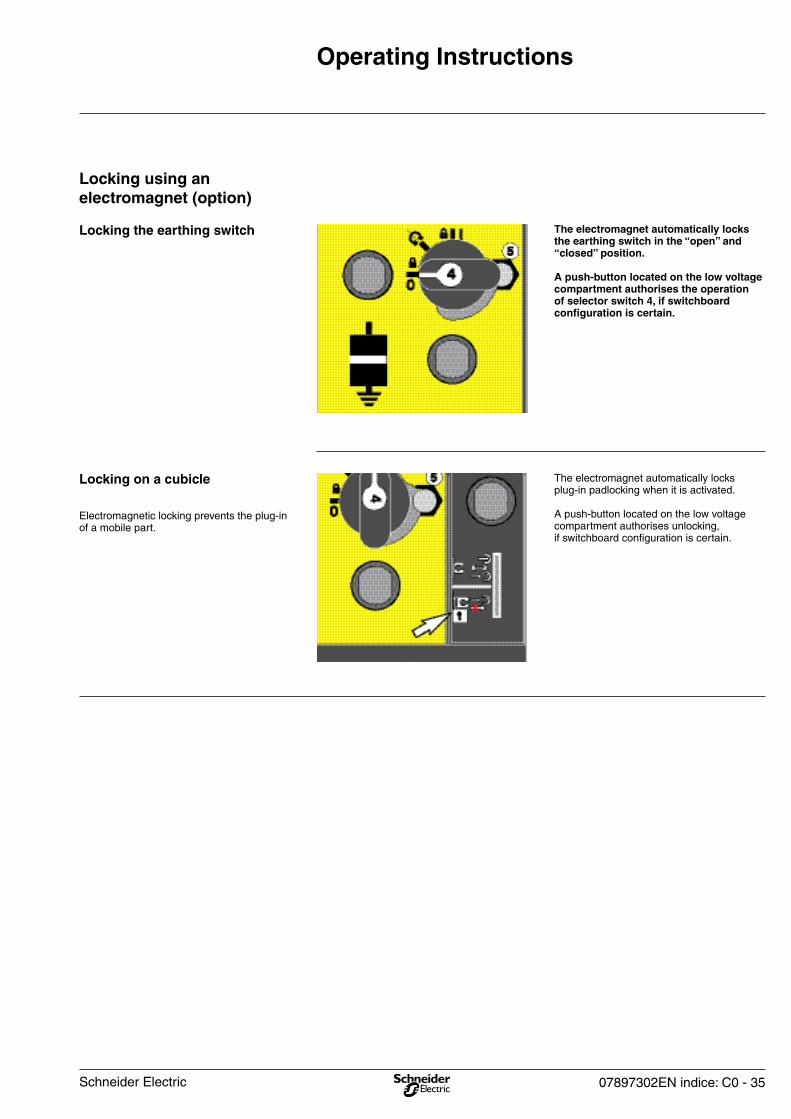
The electromagnet automatically locks plug-in padlocking when it is activated.
A push-button located on the low voltage compartment authorises unlocking,if switchboard configuration is certain.
Electromagnetic locking prevents the plug-in of a mobile part.
Locking on a cubicle
The electromagnet automatically locks the earthing switch in the “open” and “closed” position.
A push-button located on the low voltage compartment authorises the operation of selector switch 4, if switchboard configuration is certain.
Locking the earthing switch
Locking using an electromagnet (option)
Schneider Electric
36 - 07897302EN indice: C0
Corrective maintenance
Summary table
- Nylstop (self-locking nut)- Contact washer- Stop rings- Mechanical pin.
Careful: during replacement, all the following accessories must absolutely be replaced by new equipment.
For any other intervention,call upon the nearest Schneider group agents.
After each operation, carry out electric tests in compliance with the standards in force.
Corrective maintenance operations allow for defective subassemblies to be replaced.
The operations mentioned in the summary table here after can be carried out by the customeror by Schneider Electric After Sales agents.
Forward
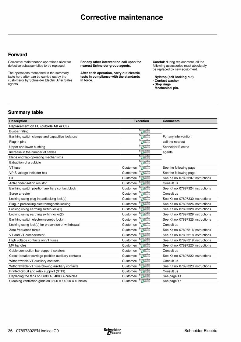
Description Execution Comments
Replacement on FU (cubicle AD or CL)
Busbar rating
Earthing switch clamps and capacitive isolators For any intervention,
Plug-in pins call the nearest
Upper and lower bushing Schneider Electric
Increase in the number of cables agents.
Flaps and flap operating mechanisms
Extraction of a cubicle
VT fuse Customer/ See the following page
VPIS voltage indicator box Customer/ See the following page
CT Customer/ See Kit no. 07897207 instructions
Anti-condensation resistor Customer/ Consult us
Earthing switch position auxiliary contact block Customer/ See Kit no. 07897324 instructions
Surge arrester Customer/ Consult us
Locking using plug-in padlocking lock(s) Customer/ See Kit no. 07897330 instructions
Plug-in padlocking electromagnetic locking Customer/ See Kit no. 07897326 instructions
Locking using earthing switch lock(1) Customer/ See Kit no. 07897328 instructions
Locking using earthing switch locks(2) Customer/ See Kit no. 07897329 instructions
Earthing switch electromagnetic lockin Customer/ See Kit no. 07897325 instructions
Locking using lock(s) for prevention of withdrawal Customer/ Consult us
Zero frequence toroid Customer/ See Kit no. 07897216 instructions
VT and VT compartment Customer/ See Kit no. 07897218 instructions
High voltage contacts on VT fuses Customer/ See Kit no. 07897219 instructions
MV handles Customer/ See Kit no. 07897220 instructions
Cable connection bar support isolators Customer/ Consult us
Circuit-breaker carriage position auxiliary contacts Customer/ See Kit no. 07897222 instructions
Withdrawable VT auxiliary contacts Customer/ Consult us
Withdrawable VT fuse blowing auxiliary contacts Customer/ See Kit no. 07897223 instructions
Printed circuit and relay support (STPI) Customer/ Consult us
Replacing the fans on 3600 A / 4000 A cubicles Customer/ See page 41
Cleaning ventilation grids on 3600 A / 4000 A cubicles Customer/ See page 17
Schneider Electric
07897302EN indice: C0 - 37
Corrective maintenance
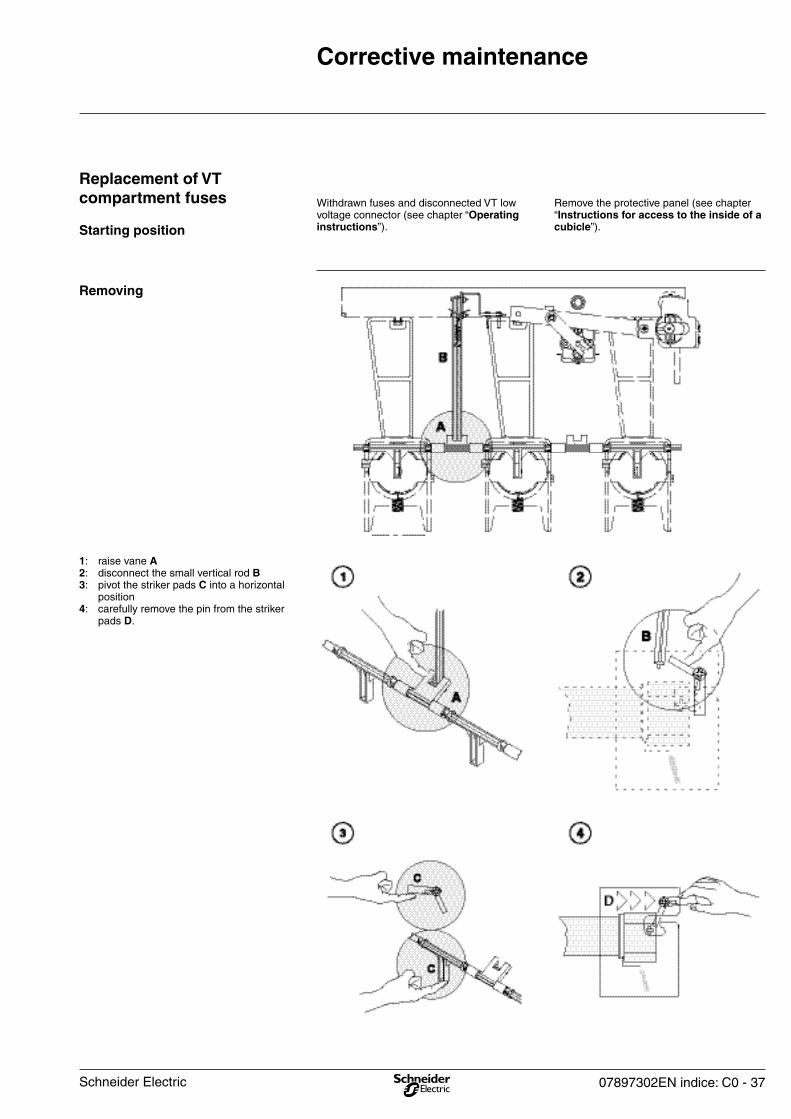
1: raise vane A2: disconnect the small vertical rod B3: pivot the striker pads C into a horizontal position4: carefully remove the pin from the striker pads D.
Removing
Remove the protective panel (see chapter “Instructions for access to the inside of a cubicle”).
Withdrawn fuses and disconnected VT low voltage connector (see chapter “Operating instructions”).Starting position
Replacement of VT compartment fuses
Schneider Electric

38 - 07897302EN indice: C0
Corrective maintenance
1: push wrench E
2: turn it towards the right and let go. The fuse is locked, check the wrench latching mechanism.
Place the fuses, with the strikers on the outside.
Fit the wrenches on the fuses (spring towards the bottom).
Place the spring on the wrench and check that it is butted against the bottom of the wrench and positioned between the two clips indicated by the arrows.
5: push wrench E and turn towards the left and let go. The fuse is unlocked.
6: Remove the wrench and the fuse.
Placing
Schneider Electric

07897302EN indice: C0 - 39
Corrective maintenance
Place protective panel (see chapter “Instructions for access to the inside of a cubicle”).
Connect the VT low voltage connector (see chapter “Operating instructions”).
Operation
3: carefully insert the pin on the striker pads D.
4: raise vane A to place the striker pads C in a vertical position.
5: connect the small vertical rod B to ensure free operation of the small rod.
Schneider Electric
40 - 07897302EN indice: C0
Corrective maintenance
Tightening torque: 0.1 mdaN.
Place the new voltage indicator box in the reverse order of removal.
Check on the characteristics label (B) that the new box corresponds to the rated voltage of your network.
- 1.7 kV to 3 kV- 3 kV to 7.2 kV- 10 kV to 24 kV.
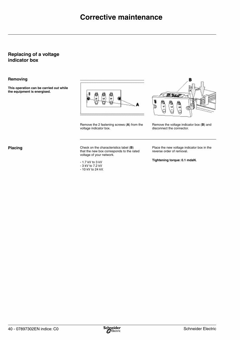
Remove the voltage indicator box (B) and disconnect the connector.
Remove the 2 fastening screws (A) from the voltage indicator box.
This operation can be carried out while the equipment is energised.
Removing
Replacing of a voltage indicator box
Placing
Schneider Electric
07897302EN indice: C0 - 41
Corrective maintenance
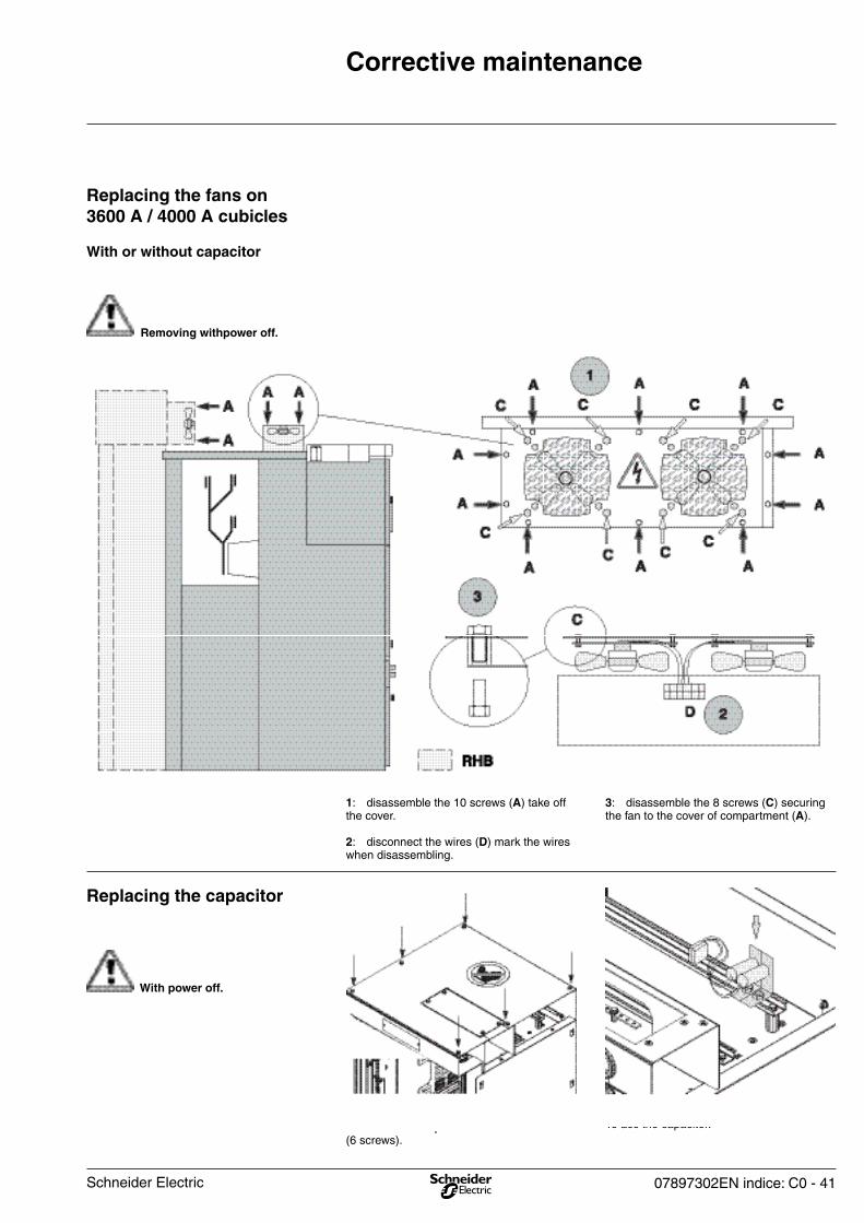
Replacing the capacitor
3: disassemble the 8 screws (C) securing the fan to the cover of compartment (A).
1: disassemble the 10 screws (A) take off the cover.
2: disconnect the wires (D) mark the wires when disassembling.
With or without capacitor
Replacing the fans on 3600 A / 4000 A cubicles
Remove the roof plate on each cubicle (6 screws).
To acc the capacitor.
With power off.
Removing withpower off.
Schneider Electric
42 - 07897302EN indice: C0
Corrective maintenance
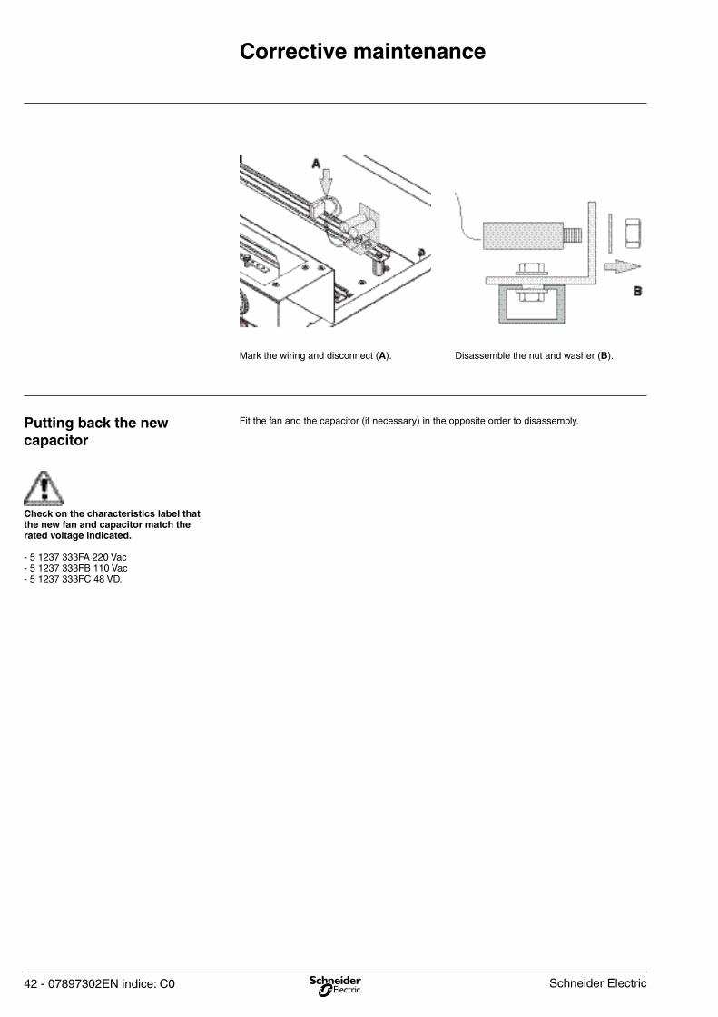
Fit the fan and the capacitor (if necessary) in the opposite order to disassembly.Putting back the new capacitor
Disassemble the nut and washer (B).Mark the wiring and disconnect (A).
Check on the characteristics label that the new fan and capacitor match the rated voltage indicated.
- 5 1237 333FA 220 Vac- 5 1237 333FB 110 Vac- 5 1237 333FC 48 VD.
Schneider Electric

07897302EN indice: C0 - 43Schneider Electric

44 - 07897302EN indice: C0 Schneider Electric
Schneider Electric Industries SAS89, boulevard Franklin RooseveltF-92506 Rueil-Malmaison CedexTel: +33 (0)1 41 29 85 00www.schneider-electric.com
07897302EN - REV. C0 10/2005
0789
7302
EN
- R
EV.
C0
a S
chne
ider
Ele
ctric
Indu
strie
s S
AS
– A
ll rig
hts
rese
rved
.
As standards, specifications and designs change from time to time, please ask for confirmation of the information given in this publication. Thisdocumenthasbeenprinted onecologicalpaper.
Publishing: Schneider Electric Industries SAS.Design: Profil.Printing:
Schneider Electric group service centers are there to provide: - engineering and technical assistance,- commissioning,- training,- preventive and corrective maintenance,- adaptation work,- spare parts.
Call your sales representative who will put you in touch with your nearest Schneider Electric group service center or directly call the following telephone number: +33 (0)4 76 57 60 60 Grenoble France.