FIBEROPTIC SERIES - Fischer Connectors · The Fischer FiberOptic Series offers the best quality and...
30
TECHNICAL SPECIFICATIONS © Fischer Connectors SA – All rights reserved Web version 1.4 - 03.2017 – Changes without prior notice FISCHER FIBEROPTIC SERIES
Transcript of FIBEROPTIC SERIES - Fischer Connectors · The Fischer FiberOptic Series offers the best quality and...

TECHNICAL SPECIFICATIONS
© Fischer Connectors SA – All rights reserved
Web version 1.4 - 03.2017 – Changes without prior notice
FISCHERFIBEROPTIC SERIES

I 1
DURABILITY
■ IP68 mated
■ IP67 unmated
■ 1,000 mating cycles
■ Performs in extreme environments
■ High optical stability
■ Low back reflection
■ Singlemode & Multimode optical fibers
■ UPC & APC polishing
■ High-end butt joint technology
■ Push-pull locking system makes it easy to mate/unmate with one hand
■ Easy operation
■ Removable monoblock mate adapter for easy access to ferrules
■ Easy maintenance
■ Easy field cleaning
PERFORMANCE EASY CLEANING EASY MATING
The Fischer FiberOptic Series offers the best quality and stability needed for an optical link, com-bined with easy mating and easy field cleaning. It performs perfectly in harsh and extreme envi-ronments and has a high ingress protection of IP68 when mated, and IP67 unmated. This rugged push pull fiber optic connector, for both indoor and outdoor applications, can aslo be available pre-cabled for maximum performance and time saving, either directly from our factory or from one of our in-country Value Added Reseller partners.
The Fischer FiberOptic Series is available in two versions:
FiberOptic FO1, FO2 & FO4A rugged connector with one (FO1), two (FO2) or four (FO4) fibers.
FiberOptic Hybrid FOHA rugged hybrid connector with two fiber channels and two electrical contacts.
KEY FEATURES
FISCHER FIBEROPTIC SERIES
FIB
ER
OP
TIC

FISCHER FIBEROPTIC
SERIES

FISCHER FIBEROPTIC SERIESBody style selection I 4
Configuration matrix I 5
Technical dimensions I 6
Optical termini and electrical contact I 20
Part numbering I 21
Protective caps I 22
Deployment accessories I 23
Quote request form I 25
Accessories I 27
Technical information I 28
I 3
ROBUST | OPTICAL PERFORMANCE | EASY CLEANING
A rugged solution ideal for :Faultless optical performance | Indoor and extreme outdoor applications | Easy field cleaning
FISCHER FIBEROPTIC SERIES
I 3
FIB
ER
OP
TIC

PLUG
CABLE MOUNTED
BODY STYLE P01
REAR ACCESSORIES Wire –Cable clamp ❍
Potting ●
CABLE MOUNTED
BODY STYLE R50
REAR ACCESSORIES Wire –Cable clamp ❍
Potting ●
PANEL FRONT MOUNTED
BODY STYLES R03 R13
REAR ACCESSORIES Wire ● ●
Cable clamp ❍ ❍
Potting ● ❍
RECEPTACLES
PANEL REAR MOUNTED
BODY STYLES R01
REAR ACCESSORIES Wire ●
Cable clamp ❍
Potting ●
FISCHER FIBEROPTIC SERIES
Technical SpecificationsI 4
FIB
ER
OP
TIC
Body style selection
– Not available for this body style❍ Partially available for this body style● Available for all body styles

PLUGS & RECEPTACLES
FISCHER FIBEROPTIC SERIES
I 5All dimensions and images shown are in millimeters and are for reference only.
Configurations matrix
Wire P01 R01 R03 R13 R50
FO1 - • • • -FO2 - • • • -FO4 - • • • -FOH - • • • -
Cable Clamp P01 R01 R03 R13 R50
FO1 • • • - •FO2 • • • • •FO4 • • • • •FOH - - - - -
Potting P01 R01 R03 R13 R50
FO1 • • • - •FO2 • • • • •FO4 • • • • •FOH • • • • •
FIB
ER
OP
TIC

FISCHER FIBEROPTIC SERIES
Technical SpecificationsI 6
FIB
ER
OP
TIC
CABLE MOUNTED
P01
BODY STYLE
PLUGS - FO1
33.5
ø13
ø 6
104
24
ø 1
1.4
98
24
ø 1
1.4
REAR ACCESSORIES
CABLE CLAMP SET POTTING SET
FO1 P01 CABLE CLAMP SET L36 D3.5 FO1 P01 POTTING SET L41 D3.5
Technical dimensions
Part number: : FO1 P01LGR1 00A00 A 000
Indicated connector P/N = delivered without contacts, termini and rear accessory

FISCHER FIBEROPTIC SERIES
I 7All dimensions and images shown are in millimeters and are for reference only.
107.4
27.5
ø 1
1.4
CABLE MOUNTED
R50
BODY STYLE
RECEPTACLES - FO1
101.4
27.5
ø 1
1.4
36.9
ø 8
.25
ø13
REAR ACCESSORIES
CABLE CLAMP SET POTTING SET
FO1 R50 CABLE CLAMP SET L36 D3.5 FO1 R50 POTTING SET L41 D3.5
Technical dimensions
Part number: : FO1 R50LGR1 00A00 A 000
Indicated connector P/N = delivered without contacts, termini and rear accessory
FIB
ER
OP
TIC

FISCHER FIBEROPTIC SERIES
Technical SpecificationsI 8
FIB
ER
OP
TIC
Technical dimensions
36.9
144
3
ø 1
3.6
ø 8
.25
Panel max.4
111) TC00.0071)
M 1
0x0.
5
ø10
9.5Panel cut-out
Top
+0.1
0
+0.10
PANEL REAR MOUNTED
R01
BODY STYLE
RECEPTACLES - FO1
1) Torque 5.0 Nm. Torque (Nm) are recommended values that may be influenced by the quality of the panel surface. Tests have to be made to evaluate the exact values.Indicated connector P/N = delivered without contacts, termini and rear accessory
41.6 67.1 72
REAR ACCESSORIES
WIRE SET CABLE CLAMP SET POTTING SET
PANEL CUT-OUT
FO1 R01 WIRE SET L18 D3.5 FO1 R01 CABLE CLAMP SET L36 D3.5 FO1 R01 POTTING SET L41 D3.5
Part number : FO1 R01LGR1 00A00 A 000

FISCHER FIBEROPTIC SERIES
I 9All dimensions and images shown are in millimeters and are for reference only.
PANEL FRONT MOUNTED
R03
BODY STYLE
41.6 72
RECEPTACLES - FO1
ø12
11.6Panel cut-out
Top
+0.1
0
+0.10
1) Torque 5.0 Nm. Torque (Nm) are recommended values that may be influenced by the quality of the panel surface. Tests have to be made to evaluate the exact values.
Technical dimensions
36.9
11.5panel max. 7
43
ø15
.6
ø8.
25
141) 111)
M12
x0.5
67
PANEL CUT-OUT
REAR ACCESSORIES
WIRE SET CABLE CLAMP SET POTTING SET
FO1 R03 WIRE SET L18 D3.5 FO1 R03 CABLE CLAMP SET L36 D3.5 FO1 R03 POTTING SET L41 D3.5
Part number:FO1 R03LGR1 00A00 A 000
FIB
ER
OP
TIC

FISCHER FIBEROPTIC SERIES
Technical SpecificationsI 10
FIB
ER
OP
TIC
Technical dimensions
27.6102.5
23
18
ø2.2 (2x)
15
ø8.
4
ø8.
25
41.27
Panel cut-out
13.3
ø2.2
18
9.9
+0.1
0
+0.10
+0.10
+0.10
Compatible with following SC & LC duplex panel cut-out
Panel cut-out
ø2.2
18
9+0
.1
0
+0.10
+0.10
41
PANEL CUT-OUT
REAR ACCESSORY
WIRE SET
FO1 R13 WIRE SET L20 D3.5
RECEPTACLES - FO1
PANEL FRONT MOUNTED
R13 - SQUARE FLANGE2)
BODY STYLE
Part number : FO1 R13LGR1 00A00 A 000
1) Torque 5.0 Nm. Torque (Nm) are recommended values that may be influenced by the quality of the panel surface. Tests have to be made to evaluate the exact values.2) Due to panel mounting with screws, sealing can’t be guaranteed at panel level.Note : indicated connector P/N = delivered without contacts, termini and rear accessry

FISCHER FIBEROPTIC SERIES
I 11All dimensions and images shown are in millimeters and are for reference only.
36.9
ø13
.5
ø 2
4
CABLE MOUNTED
P01
BODY STYLE
PLUGS - FO2/FO4
Technical dimensions
114.3
ø 1
8
REAR ACCESSORIES
CABLE CLAMP SET POTTING SET
FO2-4 P01 CABLE CLAMP SET L49 D6 FO2-4 P01 POTTING SET L49 D6.5)
ø24
ø16
.5
114.1
ø 1
8
34.6
Part number : FO2 P01LGR1 00A00 A 000FO4 P01LGR1 00A00 A 000
Note : indicated connector P/N = delivered without contacts, termini and rear accessry
FIB
ER
OP
TIC
FISCHER FIBEROPTIC SERIES
Technical SpecificationsI 12
FIB
ER
OP
TIC
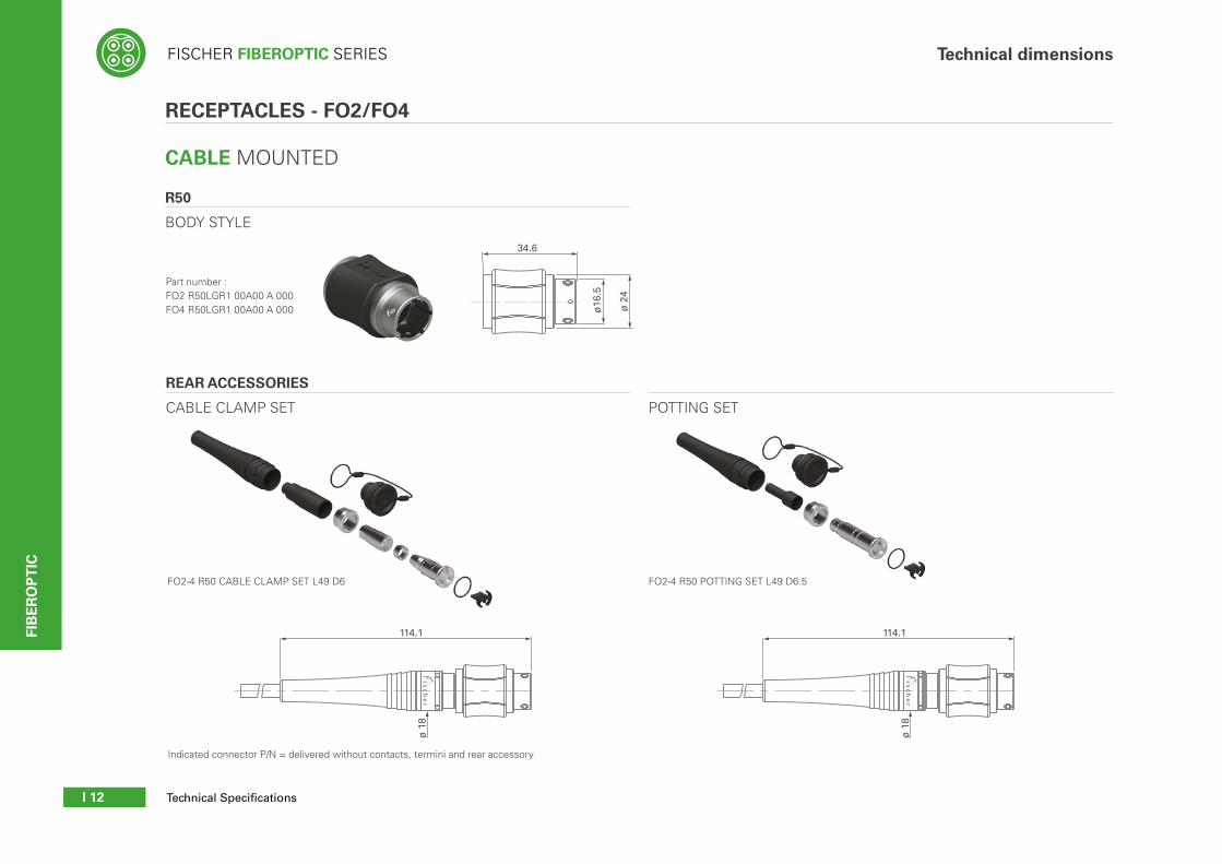
CABLE MOUNTED
R50
BODY STYLE
RECEPTACLES - FO2/FO4
34.6
ø16
.5
ø 2
4114.1
ø 1
8
REAR ACCESSORIES
CABLE CLAMP SET POTTING SET
FO2-4 R50 CABLE CLAMP SET L49 D6 FO2-4 R50 POTTING SET L49 D6.5
114.1
ø 1
8
Technical dimensions
Part number : FO2 R50LGR1 00A00 A 000FO4 R50LGR1 00A00 A 000
Indicated connector P/N = delivered without contacts, termini and rear accessory
FISCHER FIBEROPTIC SERIES
I 13All dimensions and images shown are in millimeters and are for reference only.
34.6
4
Panel max.8
ø 1
6.5
ø 2
5.8
M 2
0x1
5
ø20.1
19.1Panel cut-out
Top
+0.
10
+0.10
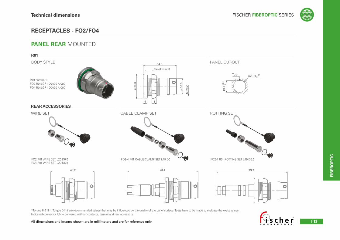
PANEL REAR MOUNTED
R01
BODY STYLE
RECEPTACLES - FO2/FO4
1) Torque 6.5 Nm. Torque (Nm) are recommended values that may be influenced by the quality of the panel surface. Tests have to be made to evaluate the exact values.Indicated connector P/N = delivered without contacts, termini and rear accessory
45.2 73.773.4
PANEL CUT-OUT
REAR ACCESSORIES
WIRE SET CABLE CLAMP SET POTTING SET
FO2 R01 WIRE SET L20 D6.5FO4 R01 WIRE SET L20 D6.5
FO2-4 R01 CABLE CLAMP SET L49 D6 FO2-4 R01 POTTING SET L49 D6.5
Technical dimensions
Part number : FO2 R01LGR1 00A00 A 000FO4 R01LGR1 00A00 A 000
FIB
ER
OP
TIC

FISCHER FIBEROPTIC SERIES
Technical SpecificationsI 14
FIB
ER
OP
TIC
Technical dimensions
PANEL FRONT MOUNTED
R03
BODY STYLE
45.273.7
RECEPTACLES - FO2/FO4
ø20.1
19.1Panel cut-out
Top
+0.
10
+0.10
1) Torque 6.5 Nm. Torque (Nm) are recommended values that may be influenced by the quality of the panel surface. Tests have to be made to evaluate the exact values.Indicated connector P/N = delivered without contacts, termini and rear accessory
34.6
Panel max.8 14
4 4
ø 1
6.5
ø 2
5.8
M 2
0x1
251) 191)
73.4
PANEL CUT-OUT
REAR ACCESSORIES
WIRE SET CABLE CLAMP SET POTTING SET
FO2 R03-R13 WIRE SET L20 D6.5FO4 R03-R13 WIRE SET L20 D6.5
FO2-4 R03-R13 CABLE CLAMP SET L49 D6 FO2-4 R03-R13 POTTING SET L49 D6.5
Part number : FO2 R03LGR1 00A00 A 000FO4 R03LGR1 00A00 A 000

FISCHER FIBEROPTIC SERIES
I 15All dimensions and images shown are in millimeters and are for reference only.
PANEL FRONT MOUNTED
R13 - SQUARE FLANGE
BODY STYLE
RECEPTACLES - FO2/FO4
26 34.619 12.5
2.5
31 24
ø3.5 (2x)
ø16
.5
ø23
.5
5.52
Panel cut-out 24±0
.1
19±0.1
ø23.8±0.1
ø3.2
Technical dimensions
1) Due to panel mounting with screws, sealing can’t be guaranteed at panel level.Indicated connector P/N = delivered without contacts, termini and rear accessory
45.2 73.4 73.7
PANEL CUT-OUT
REAR ACCESSORIES
WIRE SET CABLE CLAMP SET POTTING SET
FO2 R03-R13 WIRE SET L20 D6.5FO4 R03-R13 WIRE SET L20 D6.5
FO2-4 R03-R13 CABLE CLAMP SET L49 D6 FO2-4 R03-R13 POTTING SET L49 D6.5
Part number : FO2 R13LGR1 00A00 A 000FO4 R13LGR1 00A00 A 000
FIB
ER
OP
TIC

FISCHER FIBEROPTIC SERIES
Technical SpecificationsI 16
FIB
ER
OP
TIC
Technical dimensions
125.1
ø 2
3
RECEPTACLES - FOH
CABLE MOUNTED
R50
BODY STYLE
34.6
ø16
.5
ø 2
4
POTTING SET
FOH R50 POTTING SET L54 D10.8
CABLE MOUNTED
P01
BODY STYLE
PLUGS - FOH
125.3
ø 2
3
36.9
ø13
.5
ø 2
4
REAR ACCESSORIES
POTTING SET
FOH P01 POTTING SET L54 D10.8
Part number : FOH P01LGR1 00A00 A 000
Part number : FOH R50LGR1 00A00 A 000
Indicated connector P/N = delivered without contacts, termini and rear accessory

FISCHER FIBEROPTIC SERIES
I 17All dimensions and images shown are in millimeters and are for reference only.
Technical dimensions
Indicated connector P/N = delivered without contacts, termini and rear accessory
51.1
DIN 46247/T2
78.7
DIN 46247/T2
PANEL REAR MOUNTED
R01
BODY STYLE
RECEPTACLES - FOH
ø20.1
19.1Panel cut-out
Top
+0.
10
+0.10
34.6
4
Panel max.8
ø 1
6.5
ø 2
5.8
M 2
0x1
5191) TP00.0131)
PANEL CUT-OUT
REAR ACCESSORIES
WIRE SET POTTING SET
FOH R01 WIRE SET L26 D8 FOH R01 POTTING SET L54 D10.8
Part number : FOH R01LGR1 00A00 A 000
FIB
ER
OP
TIC

FISCHER FIBEROPTIC SERIES
Technical SpecificationsI 18
FIB
ER
OP
TIC
51.1
DIN 46247/T2
78.7
DIN 46247/T2
RECEPTACLES - FOH
PANEL FRONT MOUNTED
R03
BODY STYLE
ø20.1
19.1Panel cut-out
Top
+0.
10
+0.10
34.6
Panel max.8 14
4 4
ø 1
6.5
ø 2
5.8
M 2
0x1
251) 191)
PANEL CUT-OUT
REAR ACCESSORIES
WIRE SET POTTING SET
FOH R03-R13 WIRE SET L26 D8 FOH R03-R13 POTTING SET L54 D10.8
Technical dimensions
Part number : FOH R03LGR1 00A00 A 000
1) Torque 6.5 Nm. Torque (Nm) are recommended values that may be influenced by the quality of the panel surface. Tests have to be made to evaluate the exact values.2) For gas tightness performances, please contact us.Note : indicated connector P/N = delivered without contacts, termini and rear accessry

FISCHER FIBEROPTIC SERIES
I 19All dimensions and images shown are in millimeters and are for reference only.
78.751.2
PANEL FRONT MOUNTED
R13 - SQUARE FLANGE
BODY STYLE
RECEPTACLES - FOH
Panel cut-out 24±0
.1
19±0.1
ø23.8±0.1
ø3.2
26 34.619 12.5
2.5
31 24
ø3.5 (2x)
ø16
.5
ø23
.5
5.52
PANEL CUT-OUT
REAR ACCESSORIES
WIRE SET POTTING SET
FOH R03-R13 WIRE SET L26 D8 FOH R03-R13 POTTING SET L54 D10.8
Technical dimensions
Part number : FOH R13LGR1 00A00 A 000
1) Torque 6.5 Nm. Torque (Nm) are recommended values that may be influenced by the quality of the panel surface. Tests have to be made to evaluate the exact values.2) For gas tightness performances, please contact us.Note : indicated connector P/N = delivered without contacts, termini and rear accessry
FIB
ER
OP
TIC

FISCHER FIBEROPTIC SERIES
Technical SpecificationsI 20
FIB
ER
OP
TIC
Designation Housing Part Number
Singlemode terminus
Black (default) FO TERMINI SMA PC
Beige FO TERMINI SMA PC BG
Multimode terminus
Black (default) FO TERMINI MMA PC
Beige FO TERMINI MMA PC BG
Electrical contact (FOH Only)
Black (default) FO Termini EL M Ø1.25 SR A
Beige FO Termini EL M Ø1.25 SR A BG
Optical termini and electrical contacts

FISCHER FIBEROPTIC SERIES
I 21All dimensions and images shown are in millimeters and are for reference only.
Part numbering
Plugs■ P01 = Cable mounted
Receptacles■ R01 = Panel rear mounted, circular flange■ R03 = Panel front mounted, circular flange■ R13 = Panel front mounted, rectangular flange■ R50 = Cable mounted
■ 00 = Delivered without optical terminus■ 01 = Delivered with one optical terminus■ 02 = Delivered with two optical termini■ 03 = Delivered with three optical termini■ 04 = Delivered with four optical termini
■ A = Delivered without optical terminus ■ S = Single-mode optical terminus■ M = Multi-mode optical terminus
FO Type
Optical Contact Type
Housing Design Contacts Modification code
■ L = Push-pull locking system
Locking System
Body style
■ 00 = Delivered without electrical contact■ 01 = Delivered with one electrical contact■ 02 = Delivered with two electrical contacts■ 03 = Delivered with three electrical contacts■ 04 = Delivered with four electrical contacts
Number of Electrical contacts (FOH only)
■ GR = Grey Nickel / Chrome plating
Coating
Number of Optical TerminiLeying code
■ 000 = Default■ 001 = White PBT Insulator■ 002 = Beige electrical contact / optical termini housing
Modification code
■ A = Delivered without rear accessory■ W = Delivered with Wire Set accessory■ C = Delivered with Cable Clamp Set accessory ■ P = Delivered with Potting Set accessory
Rear accessory
Example: 000P01 S 00L GRFO 4 1 04
Rear accessory
W
Series
Number of channels (optic +Electric)
■ 1 = Code 1
■ FO = FiberOptic Series
■ 1 = Single Channel■ 2 = Two Channels■ 4 = Four Channels■ H = Hybrid
FIB
ER
OP
TIC

FISCHER FIBEROPTIC SERIES
Technical SpecificationsI 22
FIB
ER
OP
TIC
ø D
ø1
A
B
Crimp ferrule and heat shrink tube are included.
ød
øD ø1
B
A
ø1
ø3.2
~A
ø1
~A
for receptacle R01
for receptacle R50
for receptacle R03-R13
øD
2
øD
1
ø1
A
FO
FOH
FO
FOH
FOR REPLACEMENT ON PLUGS
PROTECTIVE CAPS
FOR REPLACEMENT ON RECEPTACLES
Reference Number P01 A B ø D
FO1 FOCP06C 1B2 A120 120 10.5 13
FO2/4 FOCP14C 1B2 A150 150 14 22
FOH2-2 FOHCP14C 1B2 A150 150 14 22
Reference Number A B ø d ø D øD1 øD2
FO1 R01 FOCR06P 1B2 A70 70
11.5 6 13
10 14
R03-R13 FOCR06P 1B2 E150 150- -
R50 FOCR06C 1B2 A120 120
FO2/4 R01 FOCR14P 1B2 A110 110 14 13.5 22 20 25
R03-R13 FOCR14P 1B2 E150150 14 13.5 22 - -
R50 FOCR14C 1B2 A150
FOH 2-2 R01 FOHCR14P 1B2 A110 110 14 13.5 22 20 25
R03-R13 FOHCR14P 1B2 E150150 14 13.5 22 - -
R50 FOHCR14C 1B2 A150
FISCHER FIBEROPTIC SERIES
I 23All dimensions and images shown are in millimeters and are for reference only.
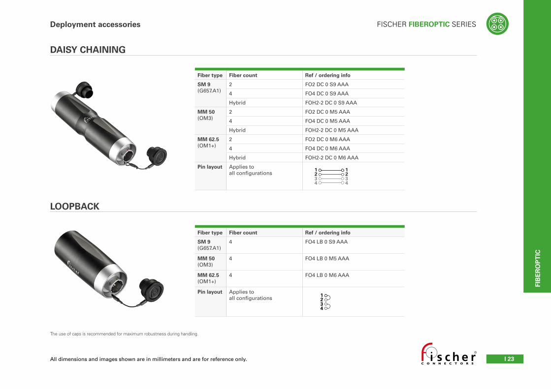
Fiber type Fiber count Ref / ordering info
SM 9(G657.A1)
2 FO2 DC 0 S9 AAA
4 FO4 DC 0 S9 AAA
Hybrid FOH2-2 DC 0 S9 AAA
MM 50(OM3)
2 FO2 DC 0 M5 AAA
4 FO4 DC 0 M5 AAA
Hybrid FOH2-2 DC 0 M5 AAA
MM 62.5(OM1+)
2 FO2 DC 0 M6 AAA
4 FO4 DC 0 M6 AAA
Hybrid FOH2-2 DC 0 M6 AAA
Pin layout Applies to all configurations
Fiber type Fiber count Ref / ordering info
SM 9(G657.A1)
4 FO4 LB 0 S9 AAA
MM 50(OM3)
4 FO4 LB 0 M5 AAA
MM 62.5(OM1+)
4 FO4 LB 0 M6 AAA
Pin layout Applies to all configurations
The use of caps is recommended for maximum robustness during handling.
1234
1234
1234
DAISY CHAINING
LOOPBACK
Deployment accessories
FIB
ER
OP
TIC

FISCHER FIBEROPTIC SERIES
Technical SpecificationsI 24
FIB
ER
OP
TIC
Deployment accessories
50 meter reels 100 meter reels
Fiber type Fiber count Ref / ordering info Ref / ordering info
SM 9(G657.A1)
1 FO1 P01P0 S9-050.0-00.0 P01P0 RAA FO1 P01P0 S9-100.0-00.0 P01P0 RAA
2 FO2 P01P0 S9-050.0-00.0 P01P0 RAC FO2 P01P0 S9-100.0-00.0 P01P0 RAC
4 FO4 P01P0 S9-050.0-00.0 P01P0 RAC FO4 P01P0 S9-100.0-00.0 P01P0 RAC
Hybrid FOH2-2 P01P0 S9-050.0-00.0 P01P0 RAC FOH2-2 P01P0 S9-100.0-00.0 P01P0 RAC
MM 50(OM3)
1 FO1 P01P0 M5-050.0-00.0 P01P0 RAA FO1 P01P0 M5-100.0-00.0 P01P0 RAA
2 FO2 P01P0 M5-050.0-00.0 P01P0 RAC FO2 P01P0 M5-100.0-00.0 P01P0 RAC
4 FO4 P01P0 M5-050.0-00.0 P01P0 RAC FO4 P01P0 M5-100.0-00.0 P01P0 RAC
Hybrid FOH2-2 P01P0 M5-050.0-00.0 P01P0 RAC FOH2-2 P01P0 M5-100.0-00.0 P01P0 RAC
150 meter reels 200 meter reels
Fiber type Fiber count Ref / ordering info Ref / ordering info
SM 9(G657.A1)
1 FO1 P01P0 S9-150.0-00.0 P01P0 RAA FO1 P01P0 S9-200.0-00.0 P01P0 RAA
2 FO2 P01P0 S9-150.0-00.0 P01P0 RAC FO2 P01P0 S9-200.0-00.0 P01P0 RAC
4 FO4 P01P0 S9-150.0-00.0 P01P0 RAC FO4 P01P0 S9-200.0-00.0 P01P0 RAC
Hybrid FOH2-2 P01P0 S9-150.0-00.0 P01P0 RAC FOH2-2 P01P0 S9-200.0-00.0 P01P0 RAC
MM 50(OM3)
1 FO1 P01P0 M5-150.0-00.0 P01P0 RAA FO1 P01P0 M5-200.0-00.0 P01P0 RAA
2 FO2 P01P0 M5-150.0-00.0 P01P0 RAC FO2 P01P0 M5-200.0-00.0 P01P0 RAC
4 FO4 P01P0 M5-150.0-00.0 P01P0 RAC FO4 P01P0 M5-200.0-00.0 P01P0 RAC
Hybrid FOH2-2 P01P0 M5-150.0-00.0 P01P0 RAC FOH2-2 P01P0 M5-200.0-00.0 P01P0 RAC
300 meter reels 450 meter reels
Fiber type Fiber count Ref / ordering info Ref / ordering info
SM 9(G657.A1)
1 FO1 P01P0 S9-300.0-00.0 P01P0 RAA FO1 P01P0 S9-450.0-00.0 P01P0 RAA
2 FO2 P01P0 S9-300.0-00.0 P01P0 RAC FO2 P01P0 S9-450.0-00.0 P01P0 RAC
4 FO4 P01P0 S9-300.0-00.0 P01P0 RAC FO4 P01P0 S9-450.0-00.0 P01P0 RAC
Hybrid FOH2-2 P01P0 S9-300.0-00.0 P01P0 RAC -
MM 50(OM3)
1 FO1 P01P0 M5-300.0-00.0 P01P0 RAA FO1 P01P0 M5-450.0-00.0 P01P0 RAA
2 FO2 P01P0 M5-300.0-00.0 P01P0 RAC FO2 P01P0 M5-450.0-00.0 P01P0 RAC
4 FO4 P01P0 M5-300.0-00.0 P01P0 RAC FO4 P01P0 M5-450.0-00.0 P01P0 RAC
Hybrid FOH2-2 P01P0 M5-300.0-00.0 P01P0 RAC -
Ltot
P01 P01
Assembled on Schill drum with OCC cable (FO1) and LEONI cable (FO2, FO4, FOH 2-2).
PRE-CONFIGURED REELS

FISCHER FIBEROPTIC SERIES
I 25
Quote request form
Cable assembly types
End A End B
Ltot
Ltot
Patch cord
Receptacle
Gas tight receptacle
Breakout
Quantity - Please use one request form per cable assembly type
Drawings are for reference only. All types exist for FO1, FO2, FO4 and FOH 2-2.
Ltot
Lb
Ltot
Lb
End A Assembly End B
FiberOptic connector
CNA - Free end No Connector
P01 - Plug
R50 - Receptacle cable mounted
R01 - Receptacle panel rear mounted
R03 - Receptacle panel front mounted
R13 - Receptacle panel square flange
Telecom connector
LC SC
FC ST
Contact End-faceAvailable for SM only
0° PC 8° APC
Breakout length* Lbfor breakout & gas tight(if applicable / min. 0.3, max 2.0)
0.5 meter
1 meter
Total length* Ltotend-to-end total (min. 0.5 except receptacles)
1 meter
2 meters
FiberOptic connectors
P01 - Plug
R50 - Receptacle cable mounted
R01 - Receptacle panel rear mounted
R03 - Receptacle panel front mounted
R13 - Receptacle* panel square flange
Contact End-faceAvailable for SM only
0° PC 8° APC
Short length receptaclesFor receptacles < 0.5 meters900 µm buffered fibers wires
For receptacles > 0.5 meters2.0 mm tight buffered wires
CONFIGURE YOUR SOLUTION
*Cable length in 0.1 meter units only. Cable length tolerance according IPC-WHMA-A-620.
LtotSingle Fiber
FIB
ER
OP
TIC

FISCHER FIBEROPTIC SERIES
Technical SpecificationsI 26
FIB
ER
OP
TIC
Quote request form
INDOOR/OUTDOOR
Supplier Brand
Fiber Count
SM 9/125G.657.A1
MM 50/125 OM3
MM 62.5/125OM1+
OCC
1
2
4
LEONI2
4
LEONIHybrid
2+2
RODENT PROOF
Supplier Brand
Fiber Count
SM 9/125G.657.1.A1
MM50/125OM3
MM 62.5/125
OM1+
LEONIGlass Fiber
2
4
METAL ARMORED
KAIPHONE 1
BRUGG2
4
Outdoor cable features OCC LEONI LEONI KAIPHONE BRUGG
Available for FO1 FO2, FO4 FO2, FO4 FO2, FO4 FO1 FO2, FO4
Best for Premium application High load application Rodent proof Metal armored Metal armored
- Overall ruggedness- Easy deployment- High end tactical cable
- High load resistance- Easy deployment- High end tactical cable
- Semi-static applications- Easy deployment- Dielectric rodent protection - High flexibility
- High rodent protection- Static & deployable applications- Ultra-light armored technology- Sensing applications
- High rodent protection- Static & deployable applications- Self supporting applications- Ultra-light armored technology- Direct burial
Technology - Tight buffered fibers- Aramid yarn- PUR jacket
- Tight buffered fibers- Aramid yarn- PUR jacket
- Tight buffered fibers- Aramid yarn / - PUR double skin jacket
- Stainless steel loose tube- Aramid yarn- LDPE jacket
- Stainless steel loose tube- Stainless steel yarn- PA Jacket
Outer diameter 2.9 mm 5.5 mm 5.5 mm 9.4 mm 3.0 mm 3.8 mm
Weight 8 kg/km 27 kg/km 28 kg/km 105 kg/km 18 kg/km 25 kg/km
Operating tensile load 300 N 600 N 1500 N 2000 N 300 N 900 N
Crush resistance 500 N/cm 1800 N/cm 800 N/cm 800 N/cm 300 N/cm 800 N/cm
Min. bending radius 1.5 cm 3.3 cm 5.5 cm 9.4 cm 3.0 cm 5.7 cm
Operating temperature -40°C to +85°C -55°C to +85°C -55°C to +85°C -40°C to + 85°C -40°C to + 70°C
CHOOSE YOUR CABLE
See our Cable Specifications for detailed information.
Available Available under special lead time - please contact your local sales departement for details.
FISCHER FIBEROPTIC SERIES
I 27
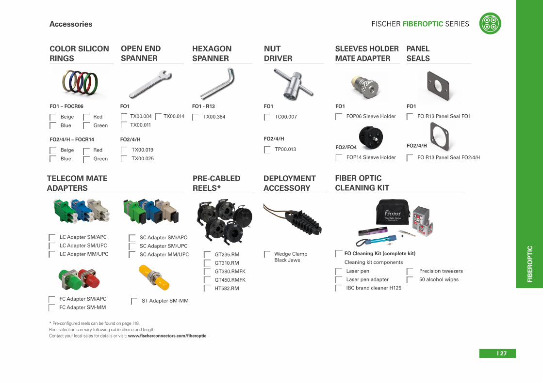
Accessories
Beige
Blue
Laser pen
Laser pen adapter
IBC brand cleaner H125
FOP06 Sleeve Holder
FO Cleaning Kit (complete kit)
COLOR SILICON RINGS
SLEEVES HOLDER MATE ADAPTER
OPEN END SPANNER
NUT DRIVER
FIBER OPTIC CLEANING KIT
Cleaning kit components
TC00.007
GT235.RM
GT310.RM
GT380.RMFK
GT450.RMFK
HT582.RM
FC Adapter SM/APC
FC Adapter SM-MMST Adapter SM-MM
Wedge Clamp Black Jaws
LC Adapter SM/APC
LC Adapter SM/UPC
LC Adapter MM/UPC
SC Adapter SM/APC
SC Adapter SM/UPC
SC Adapter MM/UPC
* Pre-configured reels can be found on page I 18. Reel selection can vary following cable choice and length.Contact your local sales for details or visit: www.fischerconnectors.com/fiberoptic
TELECOM MATE ADAPTERS
PRE-CABLED REELS*
DEPLOYMENT ACCESSORY
Precision tweezers
50 alcohol wipes
FOP14 Sleeve HolderTX00.019
TX00.025
FO1 – FOCR06
Red
Green
Beige
Blue
FO2/4/H – FOCR14
Red
Green
FO1
FO2/4/H
FO1
TP00.013
FO2/4/H
FO1
FO2/FO4
TX00.004
TX00.011
HEXAGON SPANNER
TX00.384
FO1 - R13
TX00.014
PANEL SEALS
FO R13 Panel Seal FO1
FO1
FO R13 Panel Seal FO2/4/H
FO2/4/H
FIB
ER
OP
TIC
FISCHER FIBEROPTIC SERIES
Technical SpecificationsI 28
FIB
ER
OP
TIC
Technical information
Characteristic Performance Standard
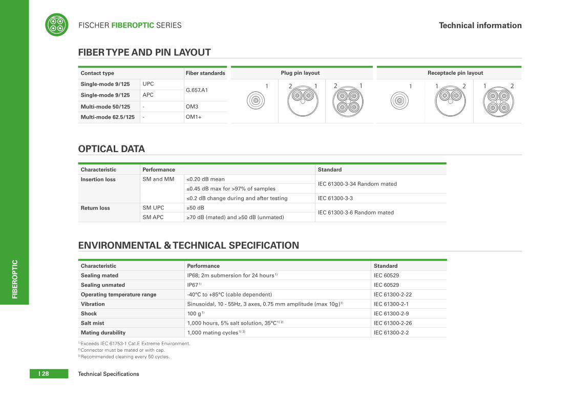
Sealing mated IP68; 2m submersion for 24 hours1) IEC 60529
Sealing unmated IP671) IEC 60529
Operating temperature range -40°C to +85°C (cable dependent) IEC 61300-2-22
Vibration Sinusoidal, 10 - 55Hz, 3 axes, 0.75 mm amplitude (max 10g)1) IEC 61300-2-1
Shock 100 g1) IEC 61300-2-9
Salt mist 1,000 hours, 5% salt solution, 35°C1) 2) IEC 61300-2-26
Mating durability 1,000 mating cycles1) 3) IEC 61300-2-2
1) Exceeds IEC 61753-1 Cat.E Extreme Environment.2) Connector must be mated or with cap.3) Recommended cleaning every 50 cycles.
Contact type Fiber standards Plug pin layout Receptacle pin layout
Single-mode 9/125 UPCG.657.A1
Single-mode 9/125 APC
Multi-mode 50/125 - OM3
Multi-mode 62.5/125 - OM1+
ENVIRONMENTAL & TECHNICAL SPECIFICATION
FIBER TYPE AND PIN LAYOUT
Characteristic Performance Standard
Insertion loss SM and MM ≤0.20 dB meanIEC 61300-3-34 Random mated
≤0.45 dB max for >97% of samples
≤0.2 dB change during and after testing IEC 61300-3-3
Return loss SM UPC ≥50 dBIEC 61300-3-6 Random mated
SM APC ≥70 dB (mated) and ≥50 dB (unmated)
OPTICAL DATA
2 1
3* 4*
2 1 1 2 1 2
4* 3*
1 1

FISCHER FIBEROPTIC SERIES
I 29
Technical information
Metal partsMaterial Finish
Designation ISO
Standard Designation Standard
Housing, nut BrassCuZn39Pb3
CW614N Chrome over Nickel
SAE-AMS 2460UNS C 38500
Back nut (plug)FO1
BrassCuZn39Pb3
CW614N Black Chrome over Nickel
SAE-AMS 2460UNS C 38500
Back nut (plug)FO2, FO4, FOH 2-2
BrassCuZn39Pb3
CW614NNickel
SAE-AMS-QQ-N-290
UNS C 38500 SAE-AMS 2404
Electrical contact BrassCuZn39Pb3
CW614NUNS C 38500
1µm Gold over Nickel
MIL-DTL-45204D Type 1 + ASTM B488 / SAE-AMS-QQ-N-290 / SAE-AMS 2404
Shell contact Stainless steel X5CrNiMo18-10 (1.4401) - -
Spring Stainless steel X10CrNi18-8 (1.4310) - -
Mantel clip Stainless steel X5CrNiMo18-10 (1.4401) - -
Sleeve holder (plug)FO1
BrassCuZn39Pb3
CW614NNickel
SAE-AMS-QQ-N-290
UNS C 38500 SAE-AMS 2404
Sleeve holder shaftFO2, FO4, FOH 2-2
Stainless steel X8CrNiS18-9 (1.4305) - -
Locking balls Stainless steel X46Cr13 (1.4034) - -
Non metallic parts Material Flammability
Ferrules & sleeves Zirconia -
Contact housing LCP UL 94 V-0
Contact bloc & sleeves holder
PBT UL 94 V-0
PEEK -
Mantel ring PTFE UL 94 V-0
O-ringsFPM (Viton®) UL 94 V-0
NBR (Nitrile) -
Sealant material Bi-component epoxy
-
Cable strain relief TPE UL 94 HB
Caps TPE UL 94 HB
Locking protection sleeve
TPE UL 94 HB
Characteristic Performance Standard
Contact count 2 contacts, ground by shell -
Current 10 [A] 1) IEC 60512-5-2-5b
Rated voltage 400 [V] r.m.s. 2) 3) EIA-364-20-B
Contact resistance (power contact) < 10 mΩ IEC 60512-2-1-2a
Contact resistance (ground contact) < 50 mΩ IEC 60512-2-1-2a
Insulation resistance > 1010 Ω IEC 60512-3-1-3a
Contact termination Solder -
Wire size AWG17 / 1 mm2 -
Test voltage AC 1.5 [kV] r.m.s IEC 60512-4-1 Test 4a
Test voltage DC 2.8 [kV] IEC 60512-4-1 Test 4a
ELECTRICAL DATA - FOH 2-2
MATERIAL & SURFACE TREATMENT
1) Current per contact at 40°C temperature rise measured on the basic curve according to IEC 60512-5-2-5b. For the max. operating current a reduction factor must be used and limitations due to the size of the wires and the permissible upper temperature limit of the materials employed must be taken into account. See page A17 for details.
2) Recommended operating voltage at sea leavel measured according to IEC 60664-1. This rated voltage is a general purpose guideline where no other electrical standard applies. In case where other standard rule a specific use of the connectors, the application-specific safety criteria shall be considered first. This must be evaluated within the framework of equipment engineering. In case where other calculation methods are preferred, please use the Test voltage to determine the specific operating voltage.
3) Based on IEC 61984 safety requirements, Fischer Connectors recommends that, for operating voltage > 50V, power should not be used without integration of an active security system. Please contact us for further information.
FIB
ER
OP
TIC