FS01 Hybrid Fiberoptic Sensoe (FS-V11)
30
54 Digital LED Bar-graph LED Manual calibration button MODE selector button The digital LED indicator is a powerful aid for optical axis alignment. Dual monitoring system The FS-V10 Series features both a digital LED indicator, which numerically displays the received light intensity, and a bar LED, which shows the level of detection stability (excess gain). The digital LED indicator can be used to align the optical axis and to display operating conditions during sensor mounting. The bar LED indicates detection stability during operation. Auto and manual calibration In addition to the conventional AUTO SET button, the FS-V10 Series features a Manual Calibration button, which enables fine adjustment. You can start detection after a quick calibration using the AUTO SET button, then make fine adjustments to the sensitivity using the Manual button. Using only the automatic calibration or only the manual calibration will provide satisfactory detection. Even an inexperienced person can make very precise adjustments. Description Features ● An Industry-first dual monitoring system ● Auto and manual calibration ● 20-bit concurrent processing chip ● High accuracy and high power ● Wire-saving 0-line or 1-line connection system Detecting Distance Thrubeam – Up to 3,600 mm (with lens) Diffuse-reflective – Up to 300 mm Definite-reflective – Up to 14 mm = = Calibration comparisons Setting procedure Fine adjustment By button Good Good No good No good Good Good Just press the button for optimal setting. Just press the button for fully automatic calibration. Settings vary depending on the operator. Sensitivity is fixed. Fine adjustment is impossible. By trimmer Calibration requires experience. Sensitivity can be set as desired. By hybrid calibration Sensitivity can be finely adjusted. Manual adjustment trimmer Sensitivity UP Sensitivity DOWN AUTO SET button Automatic SET button FS01 Series FS01 Series High Accuracy Fibreoptic Sensors <FS-V10 Series> NEW 20-bit concurrent processing chip + 12-bit A/D converter The FS-V10 Series features a newly developed 20-bit concurrent processing chip. This chip can concurrently process 12 types of control including “high-speed calculation of received light intensity”, “dual monitor display”, and “peak/bottom hold display”. Compared to general-purpose CPUs for sequential processing, this chip offers various advantages such as low current consumption, high-speed response, and reduced heat value, resulting in the improvement of overall usability.
Transcript of FS01 Hybrid Fiberoptic Sensoe (FS-V11)

54
Digital LED
Bar-graph LED
Manual calibration button
MODE selector button
The digital LED indicator is a powerful aid foroptical axis alignment.
Dual monitoring systemThe FS-V10 Series features both adigital LED indicator, whichnumerically displays the receivedlight intensity, and a bar LED, whichshows the level of detectionstability (excess gain). The digitalLED indicator can be used to alignthe optical axis and to displayoperating conditions during sensormounting. The bar LED indicatesdetection stability during operation.
Auto and manual calibrationIn addition to the conventional AUTO SET button, the FS-V10 Seriesfeatures a Manual Calibration button, which enables fine adjustment.You can start detection after a quick calibration using the AUTO SETbutton, then make fine adjustments to the sensitivity using the Manualbutton. Using only the automatic calibration or only the manualcalibration will provide satisfactory detection. Even an inexperiencedperson can make very precise adjustments.
Description
Features An Industry-first dual monitoring system Auto and manual calibration 20-bit concurrent processing chip High accuracy and high power Wire-saving 0-line or 1-line connection
system
Detecting Distance
Thrubeam – Up to 3,600 mm (with lens)
Diffuse-reflective – Up to 300 mm
Definite-reflective – Up to 14 mm
=
=
Calibrationcomparisons Setting procedure Fine adjustment
By button Good
Good
No good
No good
Good
Good
Just press the button for optimal setting.
Just press the button for fullyautomaticcalibration.
Settings vary depending on the operator.
Sensitivity is fixed. Fine adjustment is impossible.
By trimmer
Calibration requires experience. Sensitivity
can be set as desired.
By hybrid calibration
Sensitivity can be finely adjusted.
Manual adjustment trimmer
Sensitivity UP
Sensitivity DOWN
AUTO SET button
Automatic SET button
FS01 SeriesFS01 Series
High AccuracyFibreoptic Sensors
<FS-V10 Series>
NEW 20-bit concurrentprocessing chip + 12-bit A/D converterThe FS-V10 Series features a newlydeveloped 20-bit concurrent processing chip.This chip can concurrently process12 types of control including “high-speedcalculation of received light intensity”,“dual monitor display”, and “peak/bottomhold display”. Compared to general-purposeCPUs for sequential processing, this chipoffers various advantages such as lowcurrent consumption, high-speed response,and reduced heat value, resulting in theimprovement of overall usability.

High Accuracy Fibreoptic Sensors FS01
55
6
1
Phot
oele
ctric
Sens
ors
Safe
ty L
ight
Cur
tain
sPr
oxim
ity
Sens
ors
Pres
sure
Se
nsor
sPr
ogra
mm
able
Logi
c Co
ntro
llers
Visi
on S
yste
ms
Bar
Cod
eR
eade
rsD
ispl
acem
ent
Sens
ors
Hig
h Pr
ecis
ion
Sens
ors
Ana
log
Sens
orC
ontr
olle
rsVi
deo
Mic
rosc
ope
2
3
4
5
7
8
9
10
11
12
13
Tech
nica
lG
uide
Thru
beam
Mea
surin
g In
stru
men
tsC
ount
ers,
C
ontr
ol U
nits
14
seireS 01V-SF V-SF T-SF M-SF
ledomreifilpmAtinuniaM 11V-SF 1V-SF 1T-SF 1M-SF
tinunoisnapxE 21V-SF — 2T-SF 2M-SF
metsysnoitcennocgnivas-eriwenil-1.eriwylppusrewopongniriuqer,stinunoisnapxeotrewopseilppustinuniaM•
noisserppusecnerefretnilautuMstinugnidnapxeylpmisybecnerefretnistneverpyllacitamotuA• .1 .2 .2 .3
nottubelgnisahtiwsedomnoitarbilaccitamotuA4citamotua-ylluF•
gninoitisoP•tniop-2•
ytivitisnesmumixaM•
—
sedomyalpsid3gnirefforotinomlatigiDytisnetnideviecertnerrucgniwohs:rotinomytisnetnI•
eulavtimilteserpgniwohs:yalpsideulavtimiL•yllatigideulavtimilgnignahc:tnemtsujdaeulavtimiL•
.4 —
stuptuotnednepedni2sreifilpmaetarapesowtsaskrowtinuenO•
— — —
tnemtsujdanoitarbilaclaunaMelbatsujdaylenifytivitisneS• .5 .5 — .6
ledomenohtiwecnamrofrepelitasreVytisnetnirewop-hgihotycarucca-hgihmorfsnoitacilppasrevocledomenO• .7 — — .8
FS01 Series amplifier functional chart
1. FINE mode: Up to 4, TURBO/SUPER-TURBO: Up to 8 4. V1 controls T2. 7. 3 modes: FINE/TURBO/SUPER-TURBO2. Up to 4 5. Push-button 8. 2 modes: FINE/TURBO3. FINE mode: Up to 4, TURBO: Up to 8 6. Trimmer
Amplifier Variations
Fibreoptic sensors
FS01 Series
Hybrid Calibration Type:FS-V10 Series• Dual monitoring function with
bar LED and digital display• Hybrid calibration with Auto SET
button and manual adjustmentbutton
One-touch Calibration Type:FS-T Series• Fully-automatic calibration by
pressing a button• Green LED light source model
FS-T1G is also available
Manual Calibration Type:FS-M Series• Fine adjustment in calibration by
using a multi-turn trimmer• Ultra-high-speed response
model FS-M1H is also available
Digital Calibration Type:FS-V1 Series• Digital monitor function and 2
independent outputs• Control and adjustment function
for 1-line expansion units
FS01 Series features• High accuracy detection:
Detects down to 0.01 mm dia wire withthrubeam unit
• High power intensity:Detects target at the industry longest300 mm distance with reflective unit
• Wire-saving connection:1-line connection system reduces thewiring labour to 1/2 of conventional method
• Compact size with 9-mm thickness:Installing several units requires very smallspace.

1
PhotoelectricSensors
High Accuracy Fibreoptic SensorsFS01
56
SUPER TURBOMode
TURBOMode
200 mm
300 mm
FINEMode
100 mm
Model: FU-66
Functions
From ultra-high precision to ultra-high power:A single unit covers every application
The FS-V10 Series offers three levels of detection tosuit the application.
The FS-V10 Series can be used for high-precisiondetection of wire as thin as 0.01 mm in diameter with athrubeam type fibre unit. It can also be used for detectionin harsh environments where oil or dust exists. Becausethe FS-V10 Series can work in almost all applications,sensor selection is easy.
Readable digital display of moving target:Peak/bottom hold displayThe digital LED monitor can hold the displayed value.The light intensity value of a moving target can be frozento control the numerical values easily.
At a glance digital LED monitors interruptedlightThe digital LED monitor displays the light quantity at thelight-receiving element incrementally from 0 to 4095. Thisenables you to determine the degree of dust accumulationon the sensor and the deviation in the optical axis.In addition, checking the change in the light quantity withthe digital reading ensures an optimal setting value,improving the detection reliability.
Detection under harsh environmentDetection with ultra-high precision
The
rece
ived
ligh
t int
ensi
ty
Small target
Received light quantity: Large
Large target
Received light quantity: Small
FU-12Area detection fibre unit

High Accuracy Fibreoptic Sensors FS01
57
6
1
Phot
oele
ctric
Sens
ors
Safe
ty L
ight
Cur
tain
sPr
oxim
ity
Sens
ors
Pres
sure
Se
nsor
sPr
ogra
mm
able
Logi
c Co
ntro
llers
Visi
on S
yste
ms
Bar
Cod
eR
eade
rsD
ispl
acem
ent
Sens
ors
Hig
h Pr
ecis
ion
Sens
ors
Ana
log
Sens
orC
ontr
olle
rsVi
deo
Mic
rosc
ope
2
3
4
5
7
8
9
10
11
12
13
Tech
nica
lG
uide
Thru
beam
Mea
surin
g In
stru
men
tsC
ount
ers,
C
ontr
ol U
nits
14
Low excess gainOne LED does not lightduring light beam reception.That means the excess gainis +10%.
Inspection requiredTwo LEDs do not lightduring light beam reception.That means the excess gainis +5%.An immediate inspection isrequired.
1-line wire-saving connection system significantly reduces wiring timeThe FS-V10 Series uses the KEYENCE’s unique 1-line system.Power is supplied from the main unit (FS-V11) through the expansion connector so that the expansion units (FS-V12) donot require power cables.
When 10 units are used
Unstable operating conditions can be discovered at a glance using Bar LED indicatorsThe bar LED indicates detection stability using a 7-level bar LED.The bar LED shows when maintenance is required at a glance, which is difficult to notice with the digital display.
SET
LOCK
SET
OFF.DON.DOFF
D.ONL.ON
FS-T1
SET
LOCK
SET
OFF.DON.DOFF
D.ONL.ON
FS-T1
SET
LOCK
SET
OFF.DON.DOFF
D.ONL.ON
FS-T1
SET
LOCK
SET
OFF.DON.DOFF
D.ONL.ON
FS-T1
SET
LOCK
SET
OFF.DON.DOFF
D.ONL.ON
FS-T1
SET
LOCK
SET
OFF.DON.DOFF
D.ONL.ON
FS-T1
SET
LOCK
SET
OFF.DON.DOFF
D.ONL.ON
FS-T1
SET
LOCK
SET
OFF.DON.DOFF
D.ONL.ON
FS-T1
SET
LOCK
SET
OFF.DON.DOFF
D.ONL.ON
FS-T1
SET
LOCK
SET
OFF.DON.DOFF
D.ONL.ON
FS-T1
The red wires can be reduced with the 1-line system.
No. of terminal blocks20 pairs
No. of wires58
No. of crossover wires8
Man-hours120 minutes Approx.
1-line system
Space advantage
No. of terminal blocks12 pairs
No. of wires24
No. of crossover wires0
Man-hours50 minutes Approx.
Conventional system
Automatic interference preventionIn TURBO/SUPER TURBO mode, up to 8 units can bemounted side-by-side without mutual interference.(In FINE mode, up to 4 units)

1
PhotoelectricSensors
High Accuracy Fibreoptic SensorsFS01
58
Specifications
epyT)latigid,launam+hcuot-enO(noitarbilacdirbyH noitarbilaclatigiD
tinuniaM tinunoisnapxeenil-1 tinunoisnapxeenil-0 tinuniaM
ledoMNPN 11V-SF 21V-SF 01V-SF .1 1V-SF
PNP P11V-SF P21V-SF — P1V-SF
ecruosthgiL DELdeR
emitesnopseR )OBRUTREPUS(sm1/)OBRUT(sµ005/)ENIF(sµ052 sm7.1otsµ014 .2 sµ052
edomnoitarepO )elbatceles-hctiws(NO-KRAD/NO-THGIL
srotacidnI
DELdeR:rotacidnituptuOtigid-4,tnemges-7,DELdeR:rotinomDELlatigiD
DELegnarO/neerG:rotinomDELhpargraB .3
DELegnarO:rotacidninoitarbilaC .3
:srotacidnituptuOsDELdeR2
DCL:rotinomDCLlatigiD)til-kcabDELneerG/deR(
:rotacidninoitarbilaCDELegnarO
noitcnufremiT/sm01/sm04:yaled-FFO
)elbatceles(FFOremiT
/sm04:yaled-NO/sm04:yaled-FFO
FFOremiT)elbatceles-hctiws(
tuptuolortnoC .xamV1:egatlovlaudiseR,.xam)V04(Am001:rotcelloc-nepoPNProNPN .4
tiucricnoitcetorP rebrosbaegrus,noitcetorptnerruc-revo,noitcetorpytiralopesreveR
ylppusrewoP %01±CDV42ot21
noitpmusnoctnerruC .xamAm05
noitanimullitneibmA .xamxul000,02:thgilnuS,.xamxul000,01:pmaltnecsednacnI
erutarepmettneibmA 55+ot01- °C .5
lairetamgnisuoH etanobracyloP:revoC/ydoB
thgieW)elbacm-2gnidulcni(
g08.xorppA g54.xorppA g02.xorppA g08.xorppA
FS-T Series
epyTnoitarbilachcuot-enO
tinuniaM noitcetedruoloC tinunoisnapxeenil-1 tinunoisnapxeenil-0
ledoMNPN 1T-SF G1T-SF 2T-SF 0T-SF
PNP P1T-SF — P2T-SF —
ecruosthgiL DELdeR DELneerG DELdeR DELdeR
emitesnopseR sµ052 sµ052 sµ052 sm1otsµ014 .1
edomnoitarepO )elbatceles-hctiws(NO-KRAD/NO-THGIL
srotacidnI DELegnarO:rotacidninoitarbilaC,DELneerG:rotacidninoitarepoelbatS,DELdeR:rotacidnituptuO
noitcnufremiT )elbatceles-hctiws(FFOremiT,sm04:yaled-FFO,sm04:yaled-NO
tupninoitarbilaclanretxElangis
)etatsdilos,tcatnoc(tupniegatlov-noN — —
tuptuolortnoC .xamV1:egatlovlaudiseR,).xamV04(.xamAm001:PNProNPN .2
tuptuoytilibatS .xamV1:egatlovlaudiseR,).xamV04(.xamAm05:PNProNPN .3
tiucricnoitcetorP rebrosbaegrus,noitcetorptnerruc-revo,noitcetorpytiralopdesreveR
ylppusrewoP %01±CDV42ot21 %01±CDV42ot21 %01±CDV42ot21 .4 %01±CDV42ot21 .4
noitpmusnoctnerruC .xamAm53 .xamAm53 .xamAm53 .xamAm53
thgiltneibmA .xamxul000,02:thgilnuS,.xamxul000,01:pmaltnecsednacnI
erutarepmettneibmA 55+ot01- °C 55+ot01- °C 55+ot01- °C 55+ot01- °C
gnisuoH etanobracyloP:revoC/ydoB etanobracyloP:revoC/ydoB etanobracyloP:revoC/ydoB etanobracyloP:revoC/ydoB
thgieW)elbacm-2gnidulcni(
g57.xorppA g57.xorppA g04.xorppA g02.xorppA
AmplifierFS-V Series
1. The response speed varies depending on the number of expansion units connected.2. The FS-T0/M0 have no control output.3. Only the FS-T1/M1 provide stability outputs. Stability outputs for the FS-T2/T0/M2/M0 are output from the FS-T1/M1 or FS-R0.4. Power to the FS-T2/T0/M2/M0 is supplied through the FS-V11/V1/T1/M1 or FS-R0.
1. FS-V10 has no output wire and FS-R0 should be used for issuing output.2. The response time varies depending on the number of expansion units connected.3. The orange LED is normally part of the bar graph LED monitor. It is used as a calibration indicator during the setting of the sensitivity.4. FS-V1 has 2 outputs.5. When several units are connected, the allowable ambient temperature changes depending on the following conditions. To connect several units, be sure to mount them to a DIN rail (metal DIN rail). Make sure that the output current is 20 mA max. When 3 to 10 units are connected: -10 to +50°C, When 11 to 16 units are connected: -10 to +45°C

High Accuracy Fibreoptic Sensors FS01
59
6
1
Phot
oele
ctric
Sens
ors
Safe
ty L
ight
Cur
tain
sPr
oxim
ity
Sens
ors
Pres
sure
Se
nsor
sPr
ogra
mm
able
Logi
c Co
ntro
llers
Visi
on S
yste
ms
Bar
Cod
eR
eade
rsD
ispl
acem
ent
Sens
ors
Hig
h Pr
ecis
ion
Sens
ors
Ana
log
Sens
orC
ontr
olle
rsVi
deo
Mic
rosc
ope
2
3
4
5
7
8
9
10
11
12
13
Tech
nica
lG
uide
Thru
beam
Mea
surin
g In
stru
men
tsC
ount
ers,
C
ontr
ol U
nits
14
epyTnoitarbilaclaunaM
tinuniaM tinunoisnapxeenil-1 esnopserdeeps-hgiH tinunoisnapxeenil-0
ledoMNPN 1M-SF 2M-SF H1M-SF 0M-SF
PNP P1M-SF P2M-SF — —
ecruosthgiL DELdeR DELdeR DELdeR DELdeR
/tnemtsujdaytivitisneSnoitcelesedoM
)elbatceles-hctiws(OBRUT/ENIF,)rotacidnihtiw(remmirtnrut-8
emitesnopseR,)ENIF(sµ052)OBRUT(sµ005
,)ENIF(sµ052)OBRUT(sµ005
,)ENIF(sµ02)OBRUT(sµ05
sm2.1otsµ014 .1
edomnoitarepO )elbatceles-hctiws(NO-KRAD/NO-THGIL
srotacidnI DELneerG:rotacidninoitarepoelbatS,DELdeR:rotacidnituptuO
noitcnufremiT )elbatceles-hctiws(FFOremiT,sm04:yaled-FFO,sm04:yaled-NO
tuptuolortnoC .xamV1:egatlovlaudiseR,).xamV04(.xamAm001:PNProNPN .2
tuptuoytilibatS .xamV1:egatlovlaudiseR,).xamV04(.xamAm05:PNProNPN .3
tiucricnoitcetorP rebrosbaegrus,noitcetorptnerruc-revo,noitcetorpytiralopdesreveR
ylppusrewoP %01±CDV42ot21 %01±CDV42ot21 .4 %01±CDV42ot21 %01±CDV42ot21 .4
noitpmusnoctnerruC .xamAm53 .xamAm53 .xamAm53 .xamAm53
thgiltneibmA .xamxul000,02:thgilnuS,.xamxul000,01:pmaltnecsednacnI
erutarepmettneibmA 55+ot01- °C 55+ot01- °C 55+ot01- °C 55+ot01- °C
gnisuoH etanobracyloP:revoC/ydoB etanobracyloP:revoC/ydoB etanobracyloP:revoC/ydoB etanobracyloP:revoC/ydoB
thgieWm-2gnidulcni( )elbac
g57.xorppA g04.xorppA g02.xorppA g02.xorppA
1. The response speed varies depending on the number of expansion units connected.2. The FS-T0/M0 have no control output.3. Only the FS-T1/M1 provide stability outputs. Stability outputs for the FS-T2/T0/M2/M0 are output from the FS-T1/M1 or FS-R0.4. Power to the FS-T2/T0/M2/M0 is supplied through the FS-V11/V1/T1/M1 or FS-R0.
FS-M Series
Amplifier Function
1-line connection amplifiers reduce wiringand labourUp to 16 expansion units can be connected to a singlemain unit and can be freely combined.
Main units
FS-V11 :Hybrid calibrationFS-V1 :Multi-functions and
digital calibrationFS-T1 :One-touch calibrationFS-M1 :Manual calibration
Expansion units
+
FS-T1G :Green LED light sourceFS-M1H :High-speed responseFS-V12 :Hybrid calibrationFS-T2 :One-touch calibrationFS-M2 :Manual calibration
FS-V1 FS-T1 FS-M1 FS-T1G FS-M1H FS-T2 FS-M2 FS-R0 FS-T0 FS-M0 FS-R3
Connector unit 0-lineexpansion-units
FS-V11 FS-V12
0-line connection units eliminate wiring andlabourThe innovative 0-line connection system only requires anFS-R0 connector unit and a cable with a MIL connector forwiring. The units can be easily connected to an I/O card ofa PLC (programmable controller) or special board. Unitscan be freely combined to suit the application.
Board Input
DC powersupply
PLC
Cable with MIL connector
FS-V10
Terminalblock unit

1
PhotoelectricSensors
High Accuracy Fibreoptic SensorsFS01
60
FU-67G FU-77G FU-77FU-67 FU-66Z FU-63Z FU-35FZ FU-12
Thrubeam Area detection
M6, reflective with armoured tube
M4, thrubeam with armoured tube
M4, thrubeamM6, reflective M4, reflective M4, reflective with sleeve
M3, reflective
Conventional fibre
A standard fibre will easilybreak.
A single-core fibreexposed to excessivebending will easily break.
ToughFlex fibre
ToughFlex will not breakeven when sharply bent.
The 217-core fibre ishardly affected by exces-sive bending.
Tough even whenentangledEven if the fibre unit be-comes entangled, the fibreunit and the base of thehead will continue toperform.
Ready for immediateuseArmoured ToughFlexprovides a cost and laboursavings by eliminating theneed for protective tubing.
Shock-resistantThe fibre unit and the baseof the head will continue toperform even when droppedor struck by a tool.
More flexible than conventional spiral fibres
ToughFlex will not break evenwhen sharply bent.
More flexible thanconventional spiralfibres.
StandardFibre
ToughFlex Fibre PrincipleKeyence has developed the toughest fibre unit series bybundling multiple core fibres of 66 µm diameter. Thesefibres will work normally without any malfunction evenwhen they are bent to a minimum radius or when they arehit or pulled suddenly.Keyence has also maintained a long detecting distancewhile using this unique design. Including focused smallspot model, area detection model, ultra-long detectingdistance model, and thin sleeve models, every applicationcan be improved with maintenance efficiency.Plus, the latest armoured model is sheathed by a flexiblestainless steel jacket to protect the fibre from daily wearand exposure to harsh environmental conditions.
ToughFlex fibre variations
ToughFlex Fibre Features
ToughFlexwill not breakeven whensharply bent.FU-67G/77G

High Accuracy Fibreoptic Sensors FS01
61
6
1
Phot
oele
ctric
Sens
ors
Safe
ty L
ight
Cur
tain
sPr
oxim
ity
Sens
ors
Pres
sure
Se
nsor
sPr
ogra
mm
able
Logi
c Co
ntro
llers
Visi
on S
yste
ms
Bar
Cod
eR
eade
rsD
ispl
acem
ent
Sens
ors
Hig
h Pr
ecis
ion
Sens
ors
Ana
log
Sens
orC
ontr
olle
rsVi
deo
Mic
rosc
ope
2
3
4
5
7
8
9
10
11
12
13
Tech
nica
lG
uide
Thru
beam
Mea
surin
g In
stru
men
tsC
ount
ers,
C
ontr
ol U
nits
14
“Break-free” ToughFlex Fibres [Patent pending]:FU-67/77/35FZ/4FZ/5FZ/63Z/66Z/12Fibres with a minimum bend radius of 2 mm retain lightintensity even when folded. These innovative fibres can berouted just like an electric wire, enabling installation anywhere.
High-flex Fibres: FU-45X/48/49X/59/65X/68/69X/78/79These fibres, which provide higher flexibility than an electricwire, can endure repeated bends. The bendradius of 4 mm makes fibre routingeasier and saves mountingspace.
Compact Definite Reflective Fibres:FU-38/38V/38RThese fibres are excellent for detection intight spaces such as being embedded in arobot arm or on a conveyor. Detection isalmost unaffected by target backgrounds.
Area Detection Fibre: FU-12The FU-12, which provides a detecting area 10 mmwide, is suitable for detecting vibrating targetsor minute targets. A target assmall as 1.2 mm in diametercan be accurately detected.
Wafer Mapping Fibre: FU-18The FU-18 incorporates a special lens and prism andhas an aperture angle of 2° enabling ultra-narrowbeam emission. This capability is well suitedto mapping (positioning) wafers placedat a small pitch.
Long Detecting Distance, Side-view Fibre: FU-16The FU-16 provides a long detecting distance of 1.7 m and anaperture angle of 6°, enabling narrow beam emission. Almostno light reflected by surrounding objects enters the receiver,enabling stable detection.
Liquid Level Detection Fibre:FU-93The FU-93 is totally encased in aTeflon®-sheath. It is liquid resistantand can be used to reliably detect aliquid surface level.
Focused Beam Lens and Fibre: FU-21X + F-2HAThe FU-21X with the F-2HA forms a tiny beam spot 0.2mm in diameter at a detecting distanceof 7 mm. This combination is very usefulfor detecting minute targets orpositioning with high accuracy.
Fibre Unit Selection Guide (major models only)
Tube-mountable Liquid Level Detec-tion Fibre: FU-95The FU-95 is a liquid-level-detection fibrethat can be easily mounted to a tube.Because it is lightweight it can bemounted in anywhere.
Narrow-beam Fibre: FU-22XThe light diffusion angle is 10°(1/6 of conventional models),allowing narrow beam emission.This capability is ideal fordetecting minute targets.

1
PhotoelectricSensors
High Accuracy Fibreoptic SensorsFS01
62
NEW
Type Shape FeaturesDetecting distance1. (mm)Smallest2.
detectableobject
Minimumbend
radiusModelWeight
(Approx.)
Th
rub
eam
Dif
fuse
-ref
lect
ive
640
760(3600)
320
ø0.03 mm
ø0.03 mm
ø0.03 mm
ø0.01 mm
ø0.01 mm
ø0.03 mm
ø0.01 mm
ø0.1 mm
ø0.1 mm
ø0.03 mm
ø1.2 mmø0.3 mm
R25 mm
R4 mm
R2 mm
R10 mm
R4 mm
R25 mm
R10 mm
R25 mm
R10 mm
R2 mm
Standard
High-flex
ToughFlex
Thin-sleeve
Side-view
Area detection
FU-5F
Long-detecting distance
19g
FU-7F21g
FU-78A minimum bend radius of4 mm
9g
FU-5FZ
Break-free fibre
Armoured ToughFlex fibre
19g
FU-77G39g
FU-59
High-flex fibre
3g
FU-796g
FU-75FThin sleeve 10g
FU-73Long-detecting distance with sleeve
24g
FU-36XNarrow-beam type with built-in micro lens
11g
FU-32
FU-18
FU-16
Side-view type with thin sleeve 5g
8g
6g
FU-34Space-saving, side-view type 17g
FU-12Area detection fibre with a detecting width of 10 mm
23g
300370
150
460
230
570 (3000)
200
220
100
120
150
75
640
760
320
400500
250
1000
1300
650
6080
13001700
800
30
200250
100
8001000
600
TURBOSUPER TURBO SUPER TURBO is for FS-V11/12/10 only. For FS-V1 and FS-T, see FINE.
1. Detecting range varies depending on detecting distance and target diameter. Refer to "Characteristics". Detecting distance for reflective sensors were obtained using a white paper target (standard target). 2. The smallest detectable object was determined at the optimal detecting distance and sensitivity setting.3. Smallest detectable object is ø1.2 mm in TURBO mode and ø0.3 mm in FINE mode.
FINE
Free-cut
Free-cut
Free-cut
Free-cut
Free-cut
Free-cut
Free-cut
Free-cut
Free-cut
Free-cut
Free-cut
Free-cut
FU-7721g
Free-cut
Free-cut
Free-cut
Free-cut
Free-cut
ø0.01 mm(gold wire)
R25 mm
FU-4F8g
FU-6F21g
FU-6610g
Long-detectingdistance
200300
100Standard
3.
Long-detecting distance side-view type
Wafer-mapping type
LensF-1, F-2, F-4
LensF-1, F-2, F-4
LensF-1, F-2, F-4
M41.65 mm dia.
Min. bend radius of sleeve: 10 mm
4 mm dia.1.65 mm dia.
Min. bend radius of sleeve: 10 mm
M30.82 mm dia.
Do not bend sleeve.
2.5 mm dia.0.82 mm dia.
Do not bend sleeve.
3 mm dia.1.2 mm dia.
Min. bend radius of sleeve: 25 mm
M4
M4
M4
M3
3 mm dia.
1.5 mm dia.
3 mm dia.
M6
M4
3 mm dia.
4 mm dia.
4 mm dia.
M4
Fibre Unit Selection Chart

High Accuracy Fibreoptic Sensors FS01
63
6
1
Phot
oele
ctric
Sens
ors
Safe
ty L
ight
Cur
tain
sPr
oxim
ity
Sens
ors
Pres
sure
Se
nsor
sPr
ogra
mm
able
Logi
c Co
ntro
llers
Visi
on S
yste
ms
Bar
Cod
eR
eade
rsD
ispl
acem
ent
Sens
ors
Hig
h Pr
ecis
ion
Sens
ors
Ana
log
Sens
orC
ontr
olle
rsVi
deo
Mic
rosc
ope
2
3
4
5
7
8
9
10
11
12
13
Tech
nica
lG
uide
Thru
beam
Mea
surin
g In
stru
men
tsC
ount
ers,
C
ontr
ol U
nits
14
ø0.01 mm(gold wire)
R4 mm
R4 mm
ø0.01 mm(gold wire)
R25 mm
R25 mm
R25 mm
R10 mm
High-flex
Coaxial
Thin-sleeve
Side-view
FU-487g
FU-688g
FU-49x3g
FU-69X3g
FU-22X4g
FU-45X4g
FU-65X5g
FU-438g
FU-6310g
FU-63T10g
FU-3310g
FU-315g
High-flex fibre
Narrow-beam type for small-beam spot
Flush-mount type with sleeve
Screw-mount type
Long-sleeve,Flat type
Long-sleeve
Compact
Flush-mount typewith thin-sleeve
Screw-mount typewith thin-sleeve
20
25
15
1012
8
5070
30
10
6
14
40
55
25
4060
20
20
27
13
Type Shape FeaturesDetecting distance1. (mm)Smallest2.
detectableobject
Minimumbend
radiusModelWeight
(Approx.)
Dif
fuse
-ref
lect
ive
SUPER TURBO
1. Detecting distance for reflective sensors were obtained using a white paper target (standard target). 2. The smallest detectable object was determined at the optimal detecting distance and sensitivity setting.
TURBO FINE
ø0.01 mm(gold wire)
ø0.01 mm
R2 mm
ø0.01 mm(gold wire)
R2 mm
R10 mmToughFlex
Break-free fibre
Armoored ToughFlex fibre
FU-4FZ8g
FU-66Z10g
FU-6721g
FU-35FZCoaxial fibre with 0.4 mm spot diameter when used with F-2HA
Thin sleeve break-free fibre
29g
6g
FU-63Z10g
45
45
8045
3520
Free-cut
Free-cut
Free-cut
Free-cut
FU-67G
Free-cut
Free-cut
Free-cut
Free-cut
Free-cut
Free-cut
Free-cut
Free-cut
65
25
130
130
180
65
200300
100
160240
80
2028
12
70110
35
ø0.01 mm(gold wire) R25 mm
Suitable for positioning
0.2 mm spot diameter when used with F-2HA
0.4 mm spot diameter when used with F-2HA
4g
18g
4g
6g
Free-cut
Free-cut
FU-23X
FU-25
FU-21X
FU-35FA
NEW
LensF-2HA
LensF-1, F-2, F-4
Lens F-2HA, F-3HA, F-4HA
ø0.03 mm(copper wire)
M41.65 mm dia.
1.65 mm dia.
2.1 mm dia.4.8 mm dia.
1.65 mm dia.4 mm dia.
Min. bend radius of sleeve: 10 mm
Min. bend radius of sleeve: 10 mm
Min. bend radius of sleeve: 25 mm
M4
M3
1.5 mm dia.
3 mm dia.
3 mm dia.
M3
1.77 mm dia.
2.5 mm dia.
0.82 mm dia.
0.82 mm dia.
2.0 mm dia.2.8 mm dia.
Do not bend sleeve.
Do not bend sleeve.
Do not bend sleeve.
Do not bend sleeve.
Do not bend sleeve.
M41.65 mm dia.
Min. bend radius of sleeve: 10 mm
M4
M3
M6
3 mm dia.
M6
M3
M3
3 mm dia.
M6
SUPER TURBO is for FS-V11/12/10 only. For FS-V1 and FS-T, see FINE.
1
PhotoelectricSensors
High Accuracy Fibreoptic SensorsFS01
64
R40 mm
R40 mm
R10 mm–
ø0.01 mm(gold wire)
ø0.01 mm(gold wire)
R25 mm
R25 mm
R25 mm
R35 mm
R35 mm
ø0.03 mm
ø0.2 mm
ø0.1 mm
Liquid-level
Heat-resistant
Heat-resistant
Oil-proof, Chemical proof
Oil-proof, Chemical proof
FU-957g
FU-94C90g
FU-81C24g
FU-82C
Heat resistance: 350°C, glass fibre with sleeve
Heat resistance: 300°C, glass fibre with sleeve
Heat resistance: 300°C, glass fibre
Heat resistance: 300°C, glass fibre
Teflon® fibre
Teflon® fibre,side-view type
Teflon® fibre
Heat resistance: 105°C, plastic fibre
Heat resistance: 105°C, plastic fibre
Heat resistance: 180°C, plastic fibre
Heat resistance: 180°C, plastic fibre
29g
FU-83C23g
FU-8521g
FU-8733g
FU-9132g
FU-84C66g
FU-8622g
FU-8836g
FU-9271g
FU-9671g
Liquid level detection by sensor head immersion.Teflon® covered for high durability against chemicals.FU-94C heat resistant up to 200°C
Liquid level detectionby sensor headimmersion.Teflon®-sheathed
For mounting toa tube
140
210
70
140
210
70
300370 (3600)
150
640760
320
400500
200
200300
100
85110
60
120180
Transparent tube of 4 to 26 mm dia.
60
25002200
1100
870700
350
Type Shape FeaturesDetecting distance1. (mm)Smallest2.
detectableobject
Minimumbendradius
ModelWeight(Approx.)
1. Detecting range varies depending on detecting distance and target diameter. Refer to "Characteristics". Detecting distance for reflective sensors were obtained using a white paper target (standard target). 2. The smallest detectable object was determined at the optimal detecting distance and sensitivity setting.
Free-cut
R40 mm(Teflon® part)
–
FU-9378g
Liquid (except for milky white liquids)
Free-cut
Free-cut
Free-cut
Free-cut
Free-cut
Free-cut
Free-cut
Free-cut
Th
rub
eam
Dif
fuse
-ref
lect
ive
TURBOSUPER TURBO FINE
Definite-reflective
3 (Centre of detecting distance)3 (Centre of detecting distance)3 (Centre of detecting distance)
6 ±16 ±16 ±1
0 to 40 to 40 to 4
0 to 14 (Centre of detecting distance)
0 to 14 (Centre of detecting distance)
ø0.3 mm(gold wire)
ø0.08 mm(copper
wire)
R25 mm
R10 mm
ø0.01 mm(gold wire)
FU-376g
FU-385g
FU-38V5g
20g
Almost unaffectedby target colour and background
Almost unaffected by target background, side-by-side detection available
Free-cut
FU-38RFree-cut
Free-cut
Free-cut
Almost unaffected by target colour and background, long- detecting distance
Def
init
e-re
flec
tive
SUPER TURBO is for FS-V11/12/10 only. For FS-V1 and FS-T, see FINE.
LensF-2
Lens F-1, F-2, F-4
M6
M6
2.1 mm dia. M4
2.1 mm dia. M4
M4
M4
M4
M4
4.5 mm dia.
5 mm dia.
5 mm dia.
High Accuracy Fibreoptic Sensors FS01
65
6
1
Phot
oele
ctric
Sens
ors
Safe
ty L
ight
Cur
tain
sPr
oxim
ity
Sens
ors
Pres
sure
Se
nsor
sPr
ogra
mm
able
Logi
c Co
ntro
llers
Visi
on S
yste
ms
Bar
Cod
eR
eade
rsD
ispl
acem
ent
Sens
ors
Hig
h Pr
ecis
ion
Sens
ors
Ana
log
Sens
orC
ontr
olle
rsVi
deo
Mic
rosc
ope
2
3
4
5
7
8
9
10
11
12
13
Tech
nica
lG
uide
Thru
beam
Mea
surin
g In
stru
men
tsC
ount
ers,
C
ontr
ol U
nits
14
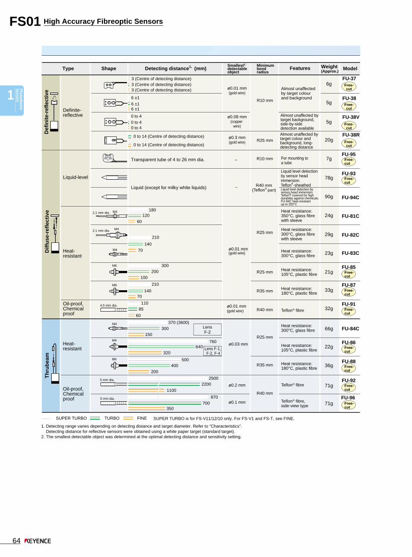
Selection Chart
epyT dradnatStnatsiser-taeH ,foorpliO
foorplacimehC053 ° epytC 003 ° epytC 081 ° epytC 501 ° epytC
erutarepmettneibmA
07+ot04- °C:77,76,21-UF(
05+ot04- ° ,C:93-UF001+ot03- ° )C
053+ot03- °C .1 003+ot04- °C .1 081+ot06- °C .1 501+ot04- °C 07+ot03- °C
lairetaM
,citsalP:erbiF:htaehS
enelyhteyloP)ssalg:93-UF(
,ssalG:erbiFlaripsleets-sselniatS:htaehS
ebut
,citsalP:erbiF:htaehS
nobracoroulFgnitaocremylop
,citsalP:erbiF:htaehS
enelyporpyloP
,citsalP:erbiFnolfeT:htaehS
Specifications
Fibre unit
1. Ambient temperature varies depending on the distance from the tip or a fibre unit. Refer to "Dimensions". The ambient temperature for the FU-87 and 88 is in dry condition.
Th
rub
eam
Dif
fuse
-ref
lect
ive
Type Configuration Feature ModelFINE TURBO SUPER
TURBOModel
Detecting distance (mm)Applicable fibre units
Focusing lens
Long-detecting distance, focusing lens
Long-detecting distance, high focusing lens
Side-view
Long-detecting distance
Ultra-long detecting distance
FU-35FA(Z)
FU-35FA(Z)
FU-21X
FU-35FA(Z)
FU-7F,86 400
260
220
220
1800
1500
1200
1500
3000
2500
2000
800
540
440
440
3600
3000
2400
3000
36002.
36002.
36002.
1000
670
550
550
36002.
3600
3000
3600
36002.
36002.
36002.
FU-77, 77G
FU-78
FU-84C
FU-7F,86
FU-77, 77G
FU-78
FU-84C
FU-7F
FU-77, 77G
FU-78
7 ±2 with beam spot diameter of 0.4 mm
0 to 20 with beam spot diameter of 4 mm
15 ±2 with beam spot diameter of 0.5 mm
7 ±2 with beam spot diameter of 0.2 mm
Focuses light beam for precise aiming. Improves the stability for the minute target detection.
Space-saving, side-view type
Greatly increases the detecting distance., Aperture angle: 15°
Greatly increases the detecting distance.Aperture angle: 8°
F-2HA
F-3HA
F-4HA
F-11.
F-2
F-4
NEW
NEW
Lens attachment
1. When using the F-1 at a temperature of 70°C or more, specify the "Heat-resistant F-1".2. "3600" is assumed as maximum because the fibre cable has the length of 2 m.

1
PhotoelectricSensors
High Accuracy Fibreoptic SensorsFS01
66
190
120
50
160
100
45
65
40
25
190
120
50
20
12
10
300
200
100
120
75
30
190
120
50
80
50
20
36
20
12
28
17
12
8
10
24
15
4
50
30
18
80
50
20
FU-5F
FU-7F
FU-5FZ
FU-77,77G
FU-59
FU-79
FU-73
FU-32
FU-12
FU-84C
FU-86
FU-4F
FU-6F
FU-66Z
FU-67, 67G
FU-35FA
FU-49X
FU-69X
FU-43
FU-63
FU-63T
FU-83C
FU-85
19g
21g
19g
21g
3g
6g
24g
5g
23g
66g
22g
8g
21g
10g
21g
6g
3g
3g
8g
10g
10g
23g
21g
Standard
High-flex
ToughFlex
Side-view
Sleeve
Area detection
Heat-resistant
High-flex
Standard
ToughFlex
Sleeve
Heat-resistant
Coaxial
When using the FS-M1H (TURBO mode) When using the FS-T1GWhen using the FS-M1H (FINE mode)
Type Shape Detecting distance1. (mm) ModelWeight(Approx.)
Th
rub
eam
Dif
fuse
-ref
lect
ive
Free-cut
Free-cut
Free-cut
Free-cut 1 m
1 m
Free-cut
Free-cut
Free-cut
Free-cut
Free-cut
Free-cut
Free-cut
Free-cut
Free-cut
Free-cut
Free-cut
Free-cut
Free-cut
Free-cut
Free-cut
1.Detecting range varies depending on detecting distance and target diameter. Refer to "Characteristics".Detecting distance for reflective sensors were obtained using a white paper target (standard target).
3 mm dia.
M4
M4
M3
1.5 mm dia.
2.5 mm dia.0.82 mm dia.
Do not bend sleeve.
M41.65 mm dia.
Min. bend radius of sleeve: 10 mm
M4
M4
3 mm dia.
3 mm dia.
1.5 mm dia.
M4
M3
M3
Do not bend sleeve.
Min. bend radius of sleeve: 10 mm
M4
M4
M4
4 mm dia.1.65 mm dia.
1.65 mm dia.
1.65 mm dia.
M6
M6
Detecting distance using FS-T1G/FS-M1H
Fibre unit
Fibre Unit Selection Chart

High Accuracy Fibreoptic Sensors FS01
67
6
1
Phot
oele
ctric
Sens
ors
Safe
ty L
ight
Cur
tain
sPr
oxim
ity
Sens
ors
Pres
sure
Se
nsor
sPr
ogra
mm
able
Logi
c Co
ntro
llers
Visi
on S
yste
ms
Bar
Cod
eR
eade
rsD
ispl
acem
ent
Sens
ors
Hig
h Pr
ecis
ion
Sens
ors
Ana
log
Sens
orC
ontr
olle
rsVi
deo
Mic
rosc
ope
2
3
4
5
7
8
9
10
11
12
13
Tech
nica
lG
uide
Thru
beam
Mea
surin
g In
stru
men
tsC
ount
ers,
C
ontr
ol U
nits
14
Specifications
epyT ecnatsidgnitceted-gnol-artlU snelgnisucoF
ledoM 4-F AH2-F AH3-F
tinuerbiF 68,F7-UF G77,77-UF AF53-UF
gnitceteDecnatsid
)mm(
)ENIF(H1M-SF 0031 0001 8 02
H1M-SF)OBRUT(
0012 0061 01 03
G1T-SF 006 005 8 51
epyT weiv-ediS ecnatsidgnitceted-gnoL
ledoM 1-F 2-F
tinuerbiF 68,F7-UF .1 G77,77-UF C48-UF .1 68,F7-UF G77,77-UF C48-UF
gnitceteDecnatsid
)mm(
)ENIF(H1M-SF 061 021 001 008 006 005
H1M-SF)OBRUT(
052 022 061 0031 0001 008
G1T-SF 07 05 54 004 053 052
STB.
Selector switch
34 pins20 pins
20 cores
3 m 34 pins3 m20 pins
20 cores
For 16 I/O unit (OP-26442) For 32 I/O unit (OP-26441)
12 to 24VDC
0 V
0 1 2 3 4 15• • • • • • •
1 112 123 134 145 156 167 178 189 1910 20
OUT 0 OUT 8
OUT 7 OUT 15/STB (stability output)*12 to 24 VDC 12 to 24 VDC
0 V 0 V
* Pin 18 can be switched to OUT 15 or STB.
Power supply wire
Brown (common to pins 9 and 19)
Blue (common to pins 10 and 20)
Connector pin number
ledoM NPN 0R-SF
ylppusrewoP .xam,%5±CDV42ot21 .1
noitpmusnoctnerruCtnerrucsulp,sselroAm02stinunoisnapxeybdemusnoc
detcennoc
stupnielbadnapxE )tuptuoytilibatsgnisunehw51(61
stuptuoforebmuN 61
emitesnopseR sm2.1otsµ014 .2
tuptuolortnoC).xamV04(.xamAm05NPN
.xamV1:egatlovlaudiseR
ledoM 3R-SF
ylppusrewoP .xam%5±CDV42ot21 .1
noitpmusnoctnerruCybdemusnoctnerrucsulp,sselroAm05
).xamAm001(rosnesdetcennoc
stupnielbadnapxE 2
langistupnItupniegatlov-nonPNP/NPNgnihctiws)etats-dilos,tcatnoc(
emitesnopseR sm1otsµ053 .2
edomtuptuO )elbatceles-hctiws(.C.N/.O.N
Attachment (with FS-M1H/T1G)
1. To use the F-1 with the FU-84C or FU-86, specify the heat-resistant F-1 when ordering.
Using stability outputThere is a selector switch locatedon the bottom of the FS-R0.By sliding the selector switch inthe direction of the arrow, thestability output of any sensor thatruns on will output from OUT 15.
Cable with MIL connector (FS-R0)(For connecting to the programmable logic controller)
Contact KEYENCE for cables for programmable logiccontrollers made by other manufacturers.
0-line systemSimple wiring connector unit
1. Change the supply voltage to meet the requirement of the input device (PLC, etc.).2. The response speed varies depending on the number of expansion units connected.
Terminal block unit
1. Change the supply voltage to meet the requirement of the input device (PLC, etc.).2. The response speed varies depending on the number of expansion units
connected.
Connector pin assignment (FS-R0)

1
PhotoelectricSensors
High Accuracy Fibreoptic SensorsFS01
68
Input/Output Circuits
3.3 kΩ
11 kΩ Pink
12 to 24 VDC
0 VContact orsolid-state input
3.3 kΩ
0 V
11 kΩ Pink12 to 24VDC
Contact orsolid-state input
470
2.7 k
NPN
PNP
0 V
IN
0 V
Power supply for sensors
12 to 24 VDC
Ω
Ω
Pho
toel
ectri
c se
nsor
mai
n ci
rcui
t
Input circuit
Brown
Black(Control output)
(Stability output)
Orange1.
Blue
Pink 2.
(External calibration)
Ove
rcur
rent
prot
ectio
n ci
rcui
t
Load100 mA max.
Load50 mA max.
12 to 24 VDC
Pho
toel
ectr
ic s
enso
rm
ain
circ
uit
Input circuit
Brown
100 mA max.
50 mA max.
Black
Orange1.
Blue
Pink 2.
(External calibration)
Ove
rcur
rent
prot
ectio
n ci
rcui
t
Load
Load
12 to 24 VDC
(Control output)
(Stability output)
FS-T1/M1/T1G/M1H
Pho
toel
ectri
c se
nsor
mai
n ci
rcui
t
Input circuit
Brown
Black(Control output)
(Control output)White
Blue
Pink (External calibration)
Ove
rcur
rent
prot
ectio
n ci
rcui
t
Load100 mA max.
Load100 mA max.
12 to 24 VDC
Pho
toel
ectr
ic s
enso
rm
ain
circ
uit
Black(Control output)
Brown
Blue
Load100mA max.
Ove
rcur
rent
prot
ectio
n ci
rcui
t
12 to 24 VDC
FS-V11 FS-V1
Blue (common to pins 10 and 20)
OUT 0 to 151.
Brown (common to pins 9 and 19)
(Control output)50mA max.
Pho
toel
ectr
ic s
enso
rm
ain
circ
uit
Load
Ove
rcur
rent
prot
ectio
n ci
rcui
t
12 to 24VDC
Pho
toel
ectr
ic s
enso
rm
ain
circ
uit
Black
0 V
(Control output)
Load100mA max.
5 to 40 VDC
Ove
rcur
rent
prot
ectio
n ci
rcui
tFS-V12
Pho
toel
ectr
ic s
enso
rm
ain
circ
uit
Black
0 V
(Control output)
Load100mA max.
5 to 40 VDC
Ove
rcur
rent
prot
ectio
n ci
rcui
t
Pho
toel
ectr
ic s
enso
rm
ain
circ
uit
Black
12 to 24 VDC
(Control output)
Load100mA max.
0 V
Ove
rcur
rent
prot
ectio
n ci
rcui
t
FS-V11P FS-V1P
Pho
toel
ectr
ic s
enso
rm
ain
circ
uit
Black
12 to 24 VDC
(Control output)
Load100mA max.
0 V
Ove
rcur
rent
prot
ectio
n ci
rcui
t
FS- V12P
Input circuitNPN
FS-T1/T1G/V1External calibration input circuit
When the external calibration input is not used,cut the pink cable at the root, or connect this cableto the positive terminal of the power supply.
PNP
FS-T1P/V1PExternal calibration input circuit
When the external calibration input is not used,cut the pink cable at the root, or connect this cableto the 0 V terminal of the power supply.
Power is supplied through the main unit.
NPN/PNP
FS-R3
Output circuitNPN
1. When the stability output is not used, cut the orangecable at the base, or connect this cable to the 0 Vterminal of the power supply.
2. The FS-M1/M1H does not have a pink cable (forexternal calibration).
PNP
1. When the stability output is not used, cut the orangecable at the base, or connect this cable to the positiveterminal of the power supply.
2. The FS-M1P does not have a pink cable.
FS-R0
When OUT 15 is switched to STB, an over-currentprotection circuit is not provided.
FS-T2/M2
Power is supplied through the main unit.
FS-T1P/M1P
Pho
toel
ectr
ic s
enso
rm
ain
circ
uit
Black(Control output)
Brown
Blue
Load100mA max.
12 to 24 VDC
Ove
rcur
rent
prot
ectio
n ci
rcui
t
Pho
toel
ectr
ic s
enso
rm
ain
circ
uit
Input circuit
Brown
(Control output)
100 mA max.
100 mA max.
(Control output)
Black
White
Blue
Pink(External calibration)
Ove
rcur
rent
prot
ectio
n ci
rcui
t
Load
Load
12 to 24 VDC
FS-T2P/M2P
Power is supplied through the main unit.
Power is supplied through the main unit.
Power is supplied through the main unit.

High Accuracy Fibreoptic Sensors FS01
69
6
1
Phot
oele
ctric
Sens
ors
Safe
ty L
ight
Cur
tain
sPr
oxim
ity
Sens
ors
Pres
sure
Se
nsor
sPr
ogra
mm
able
Logi
c Co
ntro
llers
Visi
on S
yste
ms
Bar
Cod
eR
eade
rsD
ispl
acem
ent
Sens
ors
Hig
h Pr
ecis
ion
Sens
ors
Ana
log
Sens
orC
ontr
olle
rsVi
deo
Mic
rosc
ope
2
3
4
5
7
8
9
10
11
12
13
Tech
nica
lG
uide
Thru
beam
Mea
surin
g In
stru
men
tsC
ount
ers,
C
ontr
ol U
nits
14
Adjustment
MODE MODE
MODE MODEPress this buttononce.
Received light intensity
Press this buttononce.
Display changes alternately.
Hold display(Light intensity)
Press this buttononce.
Excess gain display (%)
Press this buttononce.
Display changes alternately.
Hold display(Excess gain)
hctiwsrotcelestuptuO yalpsiD eulavdloH
NO-THGIL eulavdloh-kaeP
NO-KRAD eulavdloh-mottoB
SET
1 2
Rec
eive
d lig
ht in
tens
ity
Setting value*
Time
SET
Rec
eive
d lig
ht in
tens
ity
Max.
Setting value*
Min.Time
3 seconds minimum.
SET
1 2
3 seconds minimum.
Reflective type
With no target
Thrubeam type
With target
FS-V10 Series
Selecting displayed dataThe display changes every time the MODE button ispressed.
Displaying the setting value
Press or once while the received lightintensity is displayed. The setting value flashes for 2seconds, and then the received light intensity appearsonce more.
[Note]To change the setting value, press or whilethe setting value is flashing.
• Displaying received light intensityReceived light intensity is displayed 4095 max.
[Note]The MAX and MIN values vary depending on the fibre unitconnected.
• Displaying excess gainReceived light intensity is converted by defining thesetting value as 100 P (%).
• Stable LIGHT status is obtained with 110 P (%) or more.• Stable DARK status is obtained with 90 P (%) or less.
• Displaying the hold valueThe peak value or the minimum value of the received lightintensity or excess gain is displayed.
The setting of the output selector switch determineswhether the peak value or the minimum value is dis-played.
Setting the sensitivity(Automatic calibration)Select the sensitivity setting procedure according to thetarget condition.When the setting is completed, the setting value flashestwice.
For sensitivity adjustment using a moving target• Fully-automatic calibration
1. Pass a target through theoptical axis while pressing theSET button.
2. The calibration indicator(orange LED) flashes.
3. Release the SET button. (Theorange LED goes off.)
*The setting value is adjusted tothe midpoint of the differencebetween the maximum andminimum values of the receivedlight intensity.
If the fully-automatic calibration does not work properly, trythe two-point calibration.
• Maximum sensitivity setting1. Under the conditions on the
left, press the SET button for 3seconds or more.
2. The calibration indicator(orange LED) flashes.
3. Release the SET button. (Theorange LED goes off.)
If the detecting distance isinsufficient, try the two-pointcalibration.
For sensitivity adjustment using a stationary target• Two-point calibration
1. With no target in place, pressthe SET button and release it.(The orange LED lights.)
2. Position a target in place.Press the SET button againand release it. (The orangeLED goes off.)
*The setting value is adjusted tothe midpoint of the difference in thereceived light intensity when thetarget is absent and present.
For target positioning• Positioning calibration
1. With no target, press the SETbutton and release it. (Theorange LED lights.)
2. Place a target in the positionwhere it is to be stopped.
3. Press the SET button for 3seconds or more until thecalibration indicator (orangeLED) flashes. Release the SETbutton. (The orange LED goesoff.)
The setting value is adjusted toturn on the sensor when thetarget comes to the place where itshould be stopped.
When the reflective type is usedto detect a target with someobjects in the background, thesensitivity is set to the maximumvalue at which the backgroundobjects are not detected.

1
PhotoelectricSensors
High Accuracy Fibreoptic SensorsFS01
70
MODE
MODE
MODE
Press this button once.
Press this button once.
Current value
Press this buttonfor 3 seconds
or more.
SUPE
R
TURB
O
FINE SE
T
40m
s
10m
s
OFF
SUPE
R
TURB
O
FINE SE
T
40m
s
10m
s
OFF
SUPE
R
TURB
O
FINE SE
T
40m
s
10m
s
OFF
FINE
TURBO
SUPER
When detecting a minute difference in a short detecting distance
When the detecting distance of FINE mode is insufficient
When the environment is hostile, such as dusty
The light is steadilyreceived.
The light is irregularlyreceived.
The light is irregularlyinterrupted.
The light is steadilyinterrupted.
+15% or more+10% or more+5% or moreSetting value-5% or less-10% or less-15% or less
UP DOWN
Current value display
Press or once.
Flashing display
Wait for 2 seconds. At least3 seconds
A B
MODE
SETCH
120PA
At least3 seconds A B
MODE
SETCH
A100P
A B
MODE
SETCH
120PA
At least3 seconds
Reflective type Thrubeam type
With no target With target
Changing the setting value(Manual calibration)
Use only the button.
• When the sensitivity difference is insufficientIf the sensitivity has no allowance, “- - - -” flashes immedi-ately after the completion of the automatic calibration.
[Note]Sensitivity is set and entered even when the sensitivitydifference is insufficient. Be sure to confirm that thedetection is properly performed.
Selecting mode (Power/Timer)Power selectionOne lamp in the bar graph LED monitorflashes to show the currently selectedpower mode. Press or tochoose the desired power mode.
Timer selectionOne lamp in the bar graph LED monitorflashes to show the currently selectedoutput timer mode. Press or tochoose the desired timer mode.
[Note]Be sure to readjust the sensitivity after the power mode ischanged.
Bar graph LED monitor in normal operationThe LEDs show thereceived light intensitywith respect to thesetting value.The monitor showsthe stability level of thecurrent detection.
When the detection becomes unstable due to the changein surrounding environment or targets, readjust sensitivity.
FS-V1/FS-T SeriesSelect the sensitivity setting procedure according to thetarget condition. (FS-T has no display.)
For sensitivity adjustment using a moving target• Fully automatic calibration
1. Pass a target throughthe optical axis whilepressing the SETbutton.
2. Confirm that thecalibration indicator(yellow LED) flashes.
3. Release the SETbutton. The calibrationindicator goes off.
To detect a minute difference• Two-point calibration
1. With a target inplace, press the SETbutton and release it.The calibrationindicator (yellowLED) lights.
2. With the targetremoved, press theSET button andrelease it. Thecalibration indicatorgoes off.
For target positioning• Positioning calibration
1. With no target, pressthe SET button andrelease it. Thecalibration indicator(yellow LED) lights.
2. Place a target in theposition where it is tobe stopped.
3. Press the SET buttonuntil the calibrationindicator flashes.
4. Release the SETbutton.
For stable detection unaffected by dust• Maximum sensitivity setting
1. Under the followingconditions, press theSET button until thecalibration indicator(yellow LED) flashes.
2. Release the SETbutton. The calibra-tion indicator goesoff.
SUPE
R
TURB
O
FINE SE
T
40m
s
10m
s
OFF
SUPE
R
TURB
O
FINE SE
T
40m
s
10m
s
OFF
SUPE
R
TURB
O
FINE SE
T
40m
s
10m
s
OFF
OFF
10 ms
40 ms
Output timer OFF
OFF-delay for 10 ms
OFF-delay for 40 ms
High Accuracy Fibreoptic Sensors FS01
71
6
1
Phot
oele
ctric
Sens
ors
Safe
ty L
ight
Cur
tain
sPr
oxim
ity
Sens
ors
Pres
sure
Se
nsor
sPr
ogra
mm
able
Logi
c Co
ntro
llers
Visi
on S
yste
ms
Bar
Cod
eR
eade
rsD
ispl
acem
ent
Sens
ors
Hig
h Pr
ecis
ion
Sens
ors
Ana
log
Sens
orC
ontr
olle
rsVi
deo
Mic
rosc
ope
2
3
4
5
7
8
9
10
11
12
13
Tech
nica
lG
uide
Thru
beam
Mea
surin
g In
stru
men
tsC
ount
ers,
C
ontr
ol U
nits
14
FS-T FS-VMODE
SET+V
0V
Pink
Blue
BrownLock
Contact or solid-state input
+V
0V
Pink
Blue
BrownLock
Contact or solid state input
NPN PNP
A
A
B
A
BOptimalposition
A
A
B
A
BOptimalposition
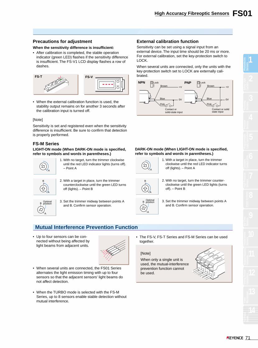
[Note]
When only a single unit isused, the mutual-interferenceprevention function cannotbe used.
Mutual Interference Prevention Function
• Up to four sensors can be con-nected without being affected bylight beams from adjacent units.
• When several units are connected, the FS01 Seriesalternates the light emission timing with up to foursensors so that the adjacent sensors’ light beams donot affect detection.
• When the TURBO mode is selected with the FS-MSeries, up to 8 sensors enable stable detection withoutmutual interference.
DARK-ON mode (When LIGHT-ON mode is specified,refer to symbols and words in parentheses.)
1. With a target in place, turn the trimmerclockwise until the red LED indicator turnsoff (lights). – Point A
2. With no target, turn the trimmer counter-clockwise until the green LED lights (turnsoff). – Point B
3. Set the trimmer midway between points Aand B. Confirm sensor operation.
FS-M SeriesLIGHT-ON mode (When DARK-ON mode is specified,refer to symbols and words in parentheses.)
1. With no target, turn the trimmer clockwiseuntil the red LED indicator lights (turns off).– Point A
2. With a target in place, turn the trimmercounterclockwise until the green LED turnsoff (lights). – Point B
3. Set the trimmer midway between points Aand B. Confirm sensor operation.
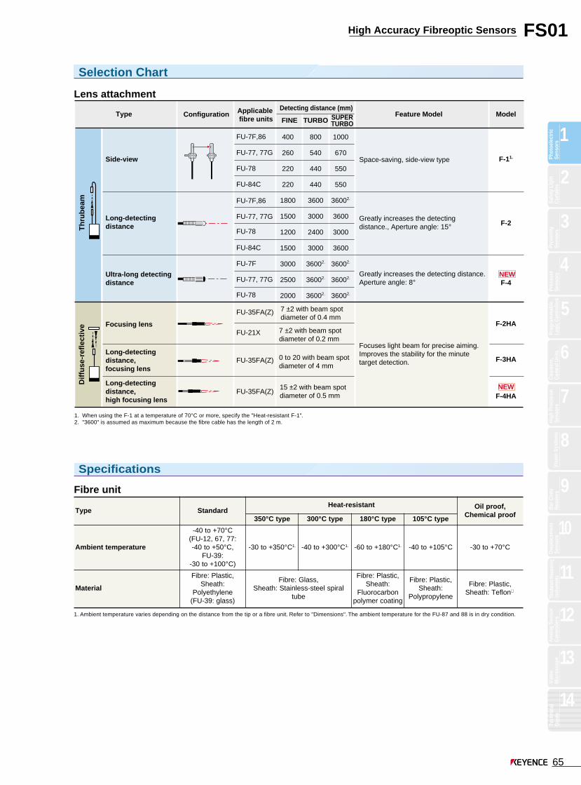
Precautions for adjustmentWhen the sensitivity difference is insufficient:• After calibration is completed, the stable operation
indicator (green LED) flashes if the sensitivity differenceis insufficient. The FS-V1 LCD display flashes a row ofdashes.
• When the external calibration function is used, thestability output remains on for another 3 seconds afterthe calibration input is turned off.
[Note]
Sensitivity is set and registered even when the sensitivitydifference is insufficient. Be sure to confirm that detectionis properly performed.
External calibration functionSensitivity can be set using a signal input from anexternal device. The input time should be 20 ms or more.For external calibration, set the key-protection switch toLOCK.
When several units are connected, only the units with thekey-protection switch set to LOCK are externally cali-brated.
• The FS-V, FS-T Series and FS-M Series can be usedtogether.

1
PhotoelectricSensors
High Accuracy Fibreoptic SensorsFS01
72
3 311 2
Stable operation level
Detection level
Stability output
“ 8 seconds”
The received light quantity does notexceed the stable operation level31 times continuously .
The received light quantity does notexceed the stable operation level8 seconds continuously .
Characteristics
0 100 200 300 400 500 600 9008007000.1
1
10
100
1000
Detecting distance X (mm) Detecting distance X (mm)Detecting distance X (mm)
0 200 400 600 800 1000 1600140012000.1
1
10
100
1000x
Exc
ess
gain
0 1000 2000 3000 4000 50000.1
1
10
100
1000x
Exc
ess
gain
x
SUPER
TURBOFINE
SUPER
TURBOFINE
SUPER
TURBOFINE
Operating level
Exc
ess
gain
FS-V/T+FU-5F, 7F ,73, 86 FS-V/T+FU-7F, 86+F-1 FS-V/T+FU-7F, 86+F-2*
Operating level Operating level
*Data was obtained using a 5-m type fiber unit.
0 100 200 3000.1
1
10
100
1000
Detecting distance X (mm) Detecting distance X (mm)Detecting distance X (mm)0 100 200 300 400 500 700600
0.1
1
10
100
1000x
Exc
ess
gain
0 50 100 150 200 2500.1
1
10
100
1000x
Exc
ess
gain
150 25050
x
SUPER
TURBOFINE
SUPER
TURBOFINE
SUPER
TURBO
FINEOperating level
Exc
ess
gain
FS-V/T+FU-59, 79 FS-V/T+FU-5FZ, 77 FS-V/T+FU-75F
Operating level Operating level
0 4 8 120.1
1
10
100
1000
Detecting distance X (mm)Detecting distance X (mm)0 10 20 30 40 50 7060
0.1
1
10
100
1000
Exc
ess
gain
6 102
SUPER
TURBOFINE
SUPER
TURBOFINE
Operating level
Exc
ess
gain
FS-V/T+FU-38FS-V/T+FU-49X, 69X
Operating level
Detecting distance X (mm)0 100 200 300 400 500
0.1
1
10
100
1000
Exc
ess
gain
SUPER
TURBOFINE
FS-V/T+FU-4F, 6F, 66, 85
Operatinglevel
x
White mat paper
x
White mat paper
X
White matpaper
When the received light quantity exceeds the detectionlevel but does not exceed the stable operation level“31 times continuously” or “for 8 seconds continuously”,the stability output is activated.
Reset: When the stability output is activated, clean thefront surface of the fibre unit or realign the optical axisso that the stable operation indicator (green LED) lightsagain. The stability output is reset when detection is donewith the stable operation indicator (green LED) turned on.
Operation chart
[Note]
When several units are connected, the stability outputs of allthe units are output from the main unit based on OR logic.
Self-diagnostic Function
Receiver excess gain vs. detecting distance (Typical) FS-T1/V1 detecting distance is the same as that for FINE mode.

High Accuracy Fibreoptic Sensors FS01
73
6
1
Phot
oele
ctric
Sens
ors
Safe
ty L
ight
Cur
tain
sPr
oxim
ity
Sens
ors
Pres
sure
Se
nsor
sPr
ogra
mm
able
Logi
c Co
ntro
llers
Visi
on S
yste
ms
Bar
Cod
eR
eade
rsD
ispl
acem
ent
Sens
ors
Hig
h Pr
ecis
ion
Sens
ors
Ana
log
Sens
orC
ontr
olle
rsVi
deo
Mic
rosc
ope
2
3
4
5
7
8
9
10
11
12
13
Tech
nica
lG
uide
Thru
beam
Mea
surin
g In
stru
men
tsC
ount
ers,
C
ontr
ol U
nits
14
100
1000
10
1
0 100 200 300 400 500 600 700 800
Exc
ess
gain
Detecting distance X (mm)
FS-M (TURBO)/ FU-5F,7F,73,86
Operating level
X100
10
1
0 200 400 600 800 1000 1200
Exc
ess
gain
Detecting distance X (mm)
FS-M (TURBO)/ FU-7F, 86+F-1
Operating level
X100
10
1
0 500 1000 1500 2000 2500 3000 3500 4000 4500 5000
Exc
ess
gain
Detecting distance X (mm)
FS-M (TURBO)/ FU-7F, 86+F-2
Operating level
X
FS-V (SUPER)+FU-4F, 6F, 66, 85FS-V (SUPER)+FU-49X, 69XFS-V (SUPER)+FU-4F, 6F, 66, 85
100
80
60
40
20
0
20
40
60
80
100
250 300
X
Y
10
5
0
5
10
15
20
5 10 15 25
X
Y
5 10 15 20 25 30 35 450
5
10
15
5
10
15
Y
40
X
Dis
tanc
e Y
(m
m)
Distance X (mm)D
ista
nce
Y (
mm
)Distance X (mm)
Dis
tanc
e Y
(m
m)
Distance X (mm)
Target: 30 cm x 30 cm
Dia.
Gold wireø0.01
Copper wireø0.1
Copper wireø0.3
20
50 100 150 200
FS-V (SUPER)+FU-7F, 86+F-1FS-V (SUPER)+FU-5F, 7F, 73, 86FS-V (SUPER)+FU-49X, 69X
2 4 6 8 10 120
1
1
2
3
4
2
3
4
Y
X
250
200
150
100
50
0
50
100
150
200
250
YX
250
200
150
100
50
0
50
150
100
200
250
X
Y
X Y
200 400 1000600 800
Gold wireø0.01
Copper wireø0.1
Copper wireø0.3
Dia. Direction A
Direction B
Dis
tanc
e Y
(m
m)
Distance X (mm)
Dis
tanc
e Y
(m
m)
Distance X (mm)D
ista
nce
Y (
mm
)Distance X (mm)
Direction B
Direction A
Direction A
Direction B
300200100 400 500 600 700 800
FS-V+FU-7F, 86+F-1FS-V (SUPER)+FU-59, 79FS-V (SUPER)+FU-7F, 86+F-2
500
400
300
200
100
0
100
200
300
400
500
1000 2000 3000 4000
YX
100
80
60
40
20
0
20
40
60
80
100
YX
0 100 200 300
5
10
15
20
25
30
ON OFF
SUPER
FINE
Dis
tanc
e Y
(m
m)
Distance X (mm)
Dis
tanc
e Y
(m
m)
Distance X (mm)
Dis
tanc
e Y
(m
m)
Distance X (mm)
Detectingdistance Hysteresis
TURBO
50 100 150 200 250
Receiver excess gain vs. detecting distance (Typical)
Operating distance vs. detecting distance (Typical) Detecting area (Typical)
Parallel displacement of optical axis (Typical)
Hysteresis (Typical)

1
PhotoelectricSensors
High Accuracy Fibreoptic SensorsFS01
74
100
10
1
0 50 100 150 200 250 300E
xces
s ga
in
Detecting distance X (mm)
FS-M (TURBO)/ FU-4F, 6F, 66, 85
Operating level
100
10
1
0 5 10 15 20 25 30 35 40 45 50
Exc
ess
gain
Detecting distance X (mm)
FS-M (TURBO)/ FU-49X,69X
Operating level
X X
White mat paperWhite mat paper
100
1000
10
1
0 50 100 150 200 250 300
Exc
ess
gain
Detecting distance X (mm)
FS-M (TURBO)/ FU-59,79
Operating level
X
Dis
tanc
e Y
(m
m)
120
90
60
30
0 25 50 75 100 125 150 175
30
90
60
120FS-M (TURBO)/ FU-4F, 6F, 66, 85
Distance X (mm)
Dis
tanc
e Y
(m
m)
12
8
4
0 5 10 15 20
4
8
12FS-M (TURBO)/ FU-49X, 69X
Distance X (mm)
X
Y
Target: 100 x 100white mat paper
X
Y
Target: 30 x 30white mat paper
Dis
tanc
e Y
(m
m)
300
400
200
100
0 500 1000 1500 2000 2500 3000 3500
100
200
300
400FS-M (TURBO)/ FU-7F, 86+F-2
Distance X (mm)
X
Y
Det
ectin
g ar
ea (
mm
)
2
4
6
8
10
12FS-M (FINE)/ FU-12
0 100 200 300 400 500
Distance X (mm)
ø1.2 (when using slit A)ø1.2 (without slit)
ø0.8 (when using slit A)
Detecting area
Diameter
Dis
tanc
e Y
(m
m)
20
40
60
80
100FS-M (FINE)/ FU-4F, 6F, 66, 85
0 1 2 3 4 5 6 7 8 9
Number of trimmer turns Number of trimmer turns
Dis
tanc
e Y
(m
m)
200
25
50
75
100
125
150
175
FS-M (TURBO)/ FU-4F, 6F, 66, 85
0 1 2 3 4 5 6 7 8 9
X
White mat paper
X
White mat paperø0.8 (without slit)
ø0.5 (without slit)
ø0.5 (when using slit A)ø0.3 (when using slit B)
Hys
tere
sis
(mm
)
1
2
3
4
5FS-M (FINE)/ FU-4F, 6F, 66, 85
0 20 40 60 80 100
Distance X (mm)
Hys
tere
sis
(mm
)
4
2
6
8
10
12FS-M (TURBO)/ FU-4F, 6F, 66, 85
0 20015010050
Distance X (mm)
Detecting distance Hysteresis
Target: 100 x 100White mat paper
ON OFF
Detecting distance Hysteresis
Target: 100 x 100White mat paper
ON OFF
Dis
tanc
e Y
(m
m)
60
80
40
20
0 25 50 75 100 125 150 175
20
40
60
80FS-M (TURBO)/ FU-59, 79
Distance X (mm)
X
Y
Parallel displacement of opticalaxis (Typical)
Operating distance vs. detecting distance (Typical)
Hysteresis (Typical)
Target diameter vs. detecting area(Typical)
Number of trimmer turns vs. detecting distance (Typical)

High Accuracy Fibreoptic Sensors FS01
75
6
1
Phot
oele
ctric
Sens
ors
Safe
ty L
ight
Cur
tain
sPr
oxim
ity
Sens
ors
Pres
sure
Se
nsor
sPr
ogra
mm
able
Logi
c Co
ntro
llers
Visi
on S
yste
ms
Bar
Cod
eR
eade
rsD
ispl
acem
ent
Sens
ors
Hig
h Pr
ecis
ion
Sens
ors
Ana
log
Sens
orC
ontr
olle
rsVi
deo
Mic
rosc
ope
2
3
4
5
7
8
9
10
11
12
13
Tech
nica
lG
uide
Thru
beam
Mea
surin
g In
stru
men
tsC
ount
ers,
C
ontr
ol U
nits
14
Hints on Correct Use
21
1 2
2
1
Single-core
Multiple-core
TransmitterReceiver
epyT epahS tinuerbifelbacilppA
ArotpadA)00562-PO(
retemaidmm3.1roF
/34/ZF4/F4/ZF53/AF53/23-UF39/19/87/Z66/66/T36/Z36/36
BrotpadA)10562-PO(
retemaidmm1roF
/95/84/V83/83/73/13/81/61-UF59/97/F57/86
Using the cutterCut the free-cut fibre unit to the desired length using theincluded cutter.
1. Insert the fibre unit into thecorresponding cutter hole tothe desired length.
2.Cut the fibre by quickly pushingthe blade all the way down.Stopping the blade midway willprevent a clean cut, therebylessening the detectingdistance. Do not use a cutterhole more than once.
Mounting the fibre unitTilt the quick-release lever. Insert the fibre unit until itstops, and then lift the quick-release lever.
• To connect a fibre unit with a small diameter, use theadapter included with the FU Series.
1.Attach the adapter to the fibre unit.
2.Fully insert the adapter into the mounting holes of theamplifier, and then lift the quick-release lever.
• The required adapter is included in each model of theFU Series. If an inadequate adapter is used, the fibreunit cannot be properly installed.
• To connect the coaxial reflective type fibre unit to theamplifier, connect the single-core fibre to the transmitterside, and connect the multiple-core fibre to the receiverside. (Connect the fibres according to the marking onthe amplifier lateral side.)

1
PhotoelectricSensors
High Accuracy Fibreoptic SensorsFS01
76
Mounting Detaching
Power lines or high-voltage lines
Protective cover
Main unit
Align the claw.
Up to 16 expansion units can be connected.Remove
the protective cover.
End unit(Included with expansion unit)
Expansion unit
1.2.
Mounting expansion unit1.Mount amplifiers to a DIN rail one at a time.
2.Slide one expansion unit toward another. Align the frontclaws of the amplifiers and push the amplifiers togetheruntil they click.
3.Fix the amplifiers together by pushing an end unit ontoeach end (The end units are included in the expansionunit. Be sure to use end units.).
1. The FS-V11/V1/T1/M1, PS-T1, CZ-K1 (1-line connection) andFS-R0 (0-line connection) can be used as the main unit.
2. The FS-V12/T2/M2, PS-T2 (1-line connection) and FS-T0/M0(0-line connection) can be used as the expansion unit.(The FS-T Series and FS-M Series can be used together.)
[Notes]• When several units are connected, confirm the ambient
temperature. (See “Specifications”.)
• To connect several units, be sure to use a DIN rail andend units.
• When detaching amplifiers from DIN rail, slide theexpansion units apart, and detach them individually.
Amplifier• When extending, use the cable
whose sectional area is morethan 0.3 mm3. Do not extendthe cable more than 100 m.(When using the expansionunit, contact Keyence.)
• If the amplifier cable is placedtogether with power lines or high-voltage lines in thesame conduit, detection error may occur due to noiseinterference, or the sensor may be damaged. Isolate theamplifier cable from these lines.
• Do not use the FS01 Series outdoors, or in a placewhere extraneous light can enter the light-receivingsurface directly.
• When the external calibration input is not used, cut thepink cable at the base, or connect this cable to the 0 Vterminal of the power supply. If the wiring is incorrect,the unit may heat up, or the sensitivity setting mayfluctuate.
• Do not remove the protectivecover of the expansionconnector on the outermostunit.
Mounting/Detaching the amplifier to/from aDIN rail or the mounting bracketHook the claw located at the amplifier cable side onto theDIN rail, and then hook the front side claw to the rail whilepressing the amplifier forward. To detach the amplifier,unhook the front claw by lifting the amplifier front sidewhile pressing it forward.
Do not detach several units at one time that are con-nected together.
Side mounting (main unit)Using the side holes of the standardmounting bracket, fix the amplifierwith the screws.

High Accuracy Fibreoptic Sensors FS01
77
6
1
Phot
oele
ctric
Sens
ors
Safe
ty L
ight
Cur
tain
sPr
oxim
ity
Sens
ors
Pres
sure
Se
nsor
sPr
ogra
mm
able
Logi
c Co
ntro
llers
Visi
on S
yste
ms
Bar
Cod
eR
eade
rsD
ispl
acem
ent
Sens
ors
Hig
h Pr
ecis
ion
Sens
ors
Ana
log
Sens
orC
ontr
olle
rsVi
deo
Mic
rosc
ope
2
3
4
5
7
8
9
10
11
12
13
Tech
nica
lG
uide
Thru
beam
Mea
surin
g In
stru
men
tsC
ount
ers,
C
ontr
ol U
nits
14
Dimensions
Free-cut
Free-cut
Free-cut
Free-cut
Free-cut
Free-cut
Free-cut
Free-cut
Free-cut
Free-cut
15(14)
2000
ø2.2
ø1.0 (ø1.13) core fibre
ø3.0 stainless steel
( ) shows FU-5FZ.
3 200012
ø2.2
Across-flats: 7, t=2
ø1.0 core fibre
M4 x P0.7Nickel-plated brass
M2.6 x P0.45
6.44.2
10
3
20
3.9 122023.3 2000
16
10
ø2.2
2 x ø3.2, ø6.6 spot-facing mounting hole
(Centre of optical axis)
ø4Stainless steel
ø1
ø2.5 (Core fibre)
20001317
3
3.6
ø4Stainless steel
ø1
ø2.5 (Core fibre)
20001317
3
3.6
FU-32
FU-34
FU-36X
FU-59
FU-73
FU-75F
10001515
0.6
2.3 ø0.82
ø1.3stainless steel
ø0.6 (Beam dia.)
ø2.5 stainless steel
1565 1920
2
0.4
2.5
ø2.2
ø1.2 stainless steel ø3.0 stainless steel
10 5Bendable area
15
1510
5*
65 1000
ø1
ø1.0 lens ø1.65 stainless steel ø4.0 stainless steel
Bendable area
*Area for mounting
10 1000
4 x ø0.265
ø1.0
core fibre
ø1.5 stainless steel
200015
10 5
65
ø2.2
ø1.65 Across-flats: 7, t=2ø1.0 core fibre
M4 x P0.7Nickel-plated brass
ø1.3
Bendablearea
2
stainless steel
3
*
ø1.0
ø0.5 core fibre
stainless steel M3 x P0.5Nickel-plated brass
ø0.82 Across-flat: 5.4, t=2
* Do not bend this area.
10001515
Thrubeam type
FU-5F/5FZ
FU-7F
FU-12
FU-16
FU-18
Unit: mm

1
PhotoelectricSensors
High Accuracy Fibreoptic SensorsFS01
78
Free-cut
Free-cut
Free-cut
Free-cut
Free-cut
Free-cut
Free-cut
Free-cut
Free-cut
2000113
ø2.2
M4 x P0.7Nickel-plated brass
M2.6 x P0.45
ø1.13core fibre
Across-flats: 7, t=2
8 x ø0.265core fibre
ø1.3
Across-flats: 7, t=2
M4 x P0.7Nickel-plated brass
M2.6 x P0.45
2000123
4 x ø0.265core fibre
ø1.0
Across-flats: 5.4, t=2M3 x P0.5Nickel-plated brass
10 1000
102000
1500
123
20480(-40 to 300˚C) (-40 to 200˚C) (-40 to 70˚C)
ø2.9 stainless steel
M4 x P0.7 stainless steel
ø4.2M2.6 x P0.45
ø1.0 fibre Across-flats: 7, t=2
Hexagonal clasp
3 200012
ø2.2
Across-flats: 7, t=2
ø1.0 core fibre
M4 x P0.7Nickel-plated brass
M2.6 x P0.45
M4 x P0.7stainless steel ø2.2
Across-flats: 7, t=2
ø1.5
ø2.9
core fibre
115
12000
ø3.7 lens
ø2.2
ø5.0 Teflon®-tube ø4.0 Teflon®-tube
1002000Embed this area in metal casing.
(22)
ø2.2
ø5.0 Teflon®-tube
ø2.8 lens
ø4.0 Teflon®-tube
1002000
(23)Embed this area in metal casing.
(4.5) Centre of optical axis
core fibre
2 x ø1.0 (ø1.13)
17 2000
ø3 stainless steel
( ) shows FU-4FZ.
2 x ø1.3
3 14 2000
2 x ø2.22 x ø1.0
ø4
Across-flats: 10, t=2
core fibreM6 x P0.75Nickel-plated brass
ø0.25core fibre
10 x ø0.125core fibre 50015
ø1.5
Across-flats: 5.4, t=2
M3 x P0.5Nickel-plated brass
1215.6
Free-cut
core fibreø1.13
1000
Stainless steelø2.9
ø4Nickel-plated brassM4 x P0.7Across-Flat : 7, t=2,
M2.6 x P=0.45
22123
Unit: mmFU-77
FU-77G
FU-78
FU-79
FU-84C
FU-86
FU-88
FU-92
FU-96
Diffuse-reflective type
FU-4F/4FZ
FU-6F
FU-21X
FU-21X+F-2HA

High Accuracy Fibreoptic Sensors FS01
79
6
1
Phot
oele
ctric
Sens
ors
Safe
ty L
ight
Cur
tain
sPr
oxim
ity
Sens
ors
Pres
sure
Se
nsor
sPr
ogra
mm
able
Logi
c Co
ntro
llers
Visi
on S
yste
ms
Bar
Cod
eR
eade
rsD
ispl
acem
ent
Sens
ors
Hig
h Pr
ecis
ion
Sens
ors
Ana
log
Sens
orC
ontr
olle
rsVi
deo
Mic
rosc
ope
2
3
4
5
7
8
9
10
11
12
13
Tech
nica
lG
uide
Thru
beam
Mea
surin
g In
stru
men
tsC
ount
ers,
C
ontr
ol U
nits
14
Free-cut
Free-cut
3 14 2000
2 x ø2.2
16 x ø0.25core fibre
Across-flats: 10, t=2ø1.0 core fibre M6 x P0.75
Nickel-plated brassø4
1
0.52
15 15 2000
ø2 ø2.8 2 x ø1
1
2.3 2.5 ø2.2 x 2ø2.1 ø2.1 stainless steel
ø4.8 stainless steel
Bendable area10 5
1565 1000
18(12)
5 10008 x ø0.265
2 x ø1.3
Across-flats: 5.4, t=2
( ) shows FU-35FZ.
ø3
ø0.5 core fibreM3 x P0.5stainless steel
core fibre
Free-cut
Free-cut
Free-cut
Free-cut
Free-cut
Free-cut
Free-cut
Free-cut
Unit: mm
15.6 15(9)
5
( ) shows FU-35FZ.
9.5 15(9)
5
( ) shows FU-35FZ.
20001520*
2 x ø0.5
ø1.3
2 x ø1.3
ø1.65stainless steel
*Do not bend this area.
core fibre
ø4 stainless steel
2
2 x ø0.265core fibre
*Do not bend this area.
ø0.82 ø1.0
stainless steel
ø3 stainless steel
15 5005*
2 x core fibre2- 4 x ø0.265
15 2000
ø1.0ø3 stainless steel
4 x ø0.265core fibre
15 1000
ø1.0ø1.5 stainless steel
200015652
10 5
9.5
2 x ø1.3
ø1.3
2 x ø0.5 ø1.65Bendable area
2 x ø3.4
core fibre stainless steel
3 10
3
t=3, Nickel-plated brass
200015652
10
2 x ø1.3
ø1.3(ø1.65)
ø1.65(ø2.0) 2 x ø0.5(ø0.65)
stainless steel
Across-flats: 7, t=2
( ) shows FU-63Z.
core fibre
M4 x P0.7Nickel-plated brass
5Bendable area
15 50015**Do not bend this area.
ø1.02 x ø0.265 Across-flats: 5.4, t=2
core fibre M3 x P0.5Nickel-plated brass
ø0.82 stainless steel
2 x ø1.0 ( ø1.13)
core fibre
3 200012
2 x ø1.3
Across-flats: 7, t=2
( ) shows FU-66Z.
M4 x P0.7stainless steel
ø2.6
2000133
2 x ø2.2M6 x P0.75Nickel-plated brass
Across-flats: 10, t=2
2 x ø1.13core fibre
50014
ø1.77
6
ø2.0
ø2.5 stainless steel
stainless steel
9 x ø0.25core fibre
ø0.5 core fibre
17
ø1.0
16 x ø0.25
ø2.2
core fibre
core fibre
ø3 stainless steel
500
Across-flats : 10, t=2,
M6 x P0.75
Nickel-plated brasscore fibre2 x ø1.13
1000
15
ø 3.8
Stainless steel
2
ø4
FU-22X
FU-23X
FU-25
FU-31
FU-33
FU-35FA/35FZ
FU-35FA(35FZ)+F-2HA
FU-35FA(35FZ)+F-3HA
FU-43
FU-45X
FU-48
FU-49X
FU-63T
FU-63/63Z
FU-65X
FU-66/66Z
FU-67
FU-67G

1
PhotoelectricSensors
High Accuracy Fibreoptic SensorsFS01
80
Free-cut
Free-cut
Free-cut
Free-cut
Free-cut
Free-cut
Free-cut
Free-cut
Free-cut
5 15 25 1590
1000
5
500 480 20
ø1.85
ø3.8
Across-flats: 7, t=2ø1.45 fibre
ø2.1 stainless steel
M4 x P0.7 stainless steel
ø5
Bendable area
(-30 to 200˚C)(-30 to 70˚C)(-30 to 350˚C)
ø3.8
Bendable area
901000
500
20 25 105
480 20(-40 to 300˚C) (-40 to 70˚C)
ø1.45 fibre ø2.1Stainless steel
Across-flats: 7, t=2 M4 x P0.7 stainless steel
ø4.2
ø3.4 stainless steel
Hexagonal clasp
Hexagonal clasp
(-40 to 300˚C)
101000
500
143
20480(-40 to 300˚C) (-40 to 200˚C) (-40 to 70˚C)
ø1.45 fibre
ø3.4 stainless steel
Across-flats: 7, t=2 M4 x P=0.7 stainless steelø4.2
ø2.6
Hexagonal clasp
3 14 2000
2 x ø2.22 x ø 1.0
ø4
Across-flats: 10, t=2
core fibre M6 x P0.75Nickel-plated brass
200013
Across-flats: 10, t=2M6 x P0.75stainless steel
ø2.2
ø4.9
2 x ø1.5 core fibre
31
2 x
2000 100*Embed this area in metal casing.
(20)*
core fibre2 x ø1.0 2 x ø1.3
ø4.5 Teflon®-tube
ø4.2 Teflon®-tube
*Do not bend or cut this portion.
(80)*
(12.5)7 ø6, Teflon® tube
Resin casinginserted
*Do not bend or cut this portion.
2000 200
2 x ø1.3
(80)*
(12.5)7ø6 Teflon® sheath
Resin casinginserted
*Do not bend or cut this portion.
2008 10
Across-flats: 6.8,hexagonal clasp
Stainless steelø3.9 spiral tube
2000
1120 2000
(0.9)
8.4
15.4ø1 x 2
2 x ø3.2mounting hole
15 5
ø12 x
719 2000
8.414.4
3
5
2 x ø3.4, ø6 spot facingmounting hole
5.5
12
3.57
19 2000
2 x ø3.2, ø6.2 spot facing mounting hole
2 x ø1
4 6
4.3 5.5
12
3.57
19 2000
2 x ø12 x ø3.2, ø6.2 spot facing mounting hole
6.514.9
2000
3.8 29
(4.6)
(20)* *Do not bend this part.
3
2 x ø3.5, ø6.2 spot facing mounting hole
4x ø0.265core fibre
ø1
Across-flats: 5.4, t=2
M3 x P0.5 Nickel-plated brass
100010
123 2000
2 x ø1.02-4 x ø0.265
ø3
core fibre
Across-flats: 7, t=2
M4 x P0.7stainless steel
Free-cutFU-68
FU-69X
FU-81C
FU-82C
FU-83C
FU-85
FU-87
FU-91
Definite-reflective typeFU-37
FU-38
FU-38R
FU-38V
Liquid-level type
FU-93
FU-94C
FU-95
Unit: mm

High Accuracy Fibreoptic Sensors FS01
81
6
1
Phot
oele
ctric
Sens
ors
Safe
ty L
ight
Cur
tain
sPr
oxim
ity
Sens
ors
Pres
sure
Se
nsor
sPr
ogra
mm
able
Logi
c Co
ntro
llers
Visi
on S
yste
ms
Bar
Cod
eR
eade
rsD
ispl
acem
ent
Sens
ors
Hig
h Pr
ecis
ion
Sens
ors
Ana
log
Sens
orC
ontr
olle
rsVi
deo
Mic
rosc
ope
2
3
4
5
7
8
9
10
11
12
13
Tech
nica
lG
uide
Thru
beam
Mea
surin
g In
stru
men
tsC
ount
ers,
C
ontr
ol U
nits
14
18
4
6.7 2.1
78
12 min.
(Maximum when the cover is opened)
ø3.9, 5-core
Cable length: 2 m
Brown/Blue: 0.34 mm2
Black/White/Pink: 0.18 mm2
(12.5)
(33)
1.1 6
28.5
35.48.4
53.5
DIN-rail mounting
( (
9
4
6.7
78
12 min.
(Maximum when the cover is opened)
*ø3.9 5-core
Cable length: 2 m
Brown/Blue: 0.34 mm2
Black/Orange/Pink: 0.18 mm2
* FS-M1: ø3.9 4-core xBrown/Blue: 0.34 mm2
Black/Orange: 0.18 mm2
(12.5)
(33)
1.1 6
28.5
35.48.4
53.5
DIN-rail mounting 135°max.
( (
9
4
6.7
78
(12.5)
(33)
1.1 6
28.5
35.48.4
53.5
11min.
ø2.6 single-core x 0.34 mm2
Cable length: 2 mFS-T2/M2 (1-line expansion unit)
(Maximum when the cover is opened)
DIN-rail mounting
4
6.7
78
(33)
1.1 6
28.5
35.48.4
53.53.6
(Maximum when the cover is opened)
DIN-rail mounting
9
FS-T0/M0 (0-line expansion unit)
3
0.7
36.5
3.8
22.8
25.6 25.4
816
30.8
9
15
313
9
0.7
6.7
4(33)28.5
20.7 35.4
(13)
66
3
9
0.7
6.7
4(33) 28.5
20.7 35.4
(13)
66
2 x (4.4 x 3.4), spot facing: ø7, d=4
Rear of mounting bracket
2 x ø3.4,spot facing: ø6, d=2.7
12 min.
11 min.
12 min.
ø3.9, 3-core (Brown/Blue/Black) x 0.34 mm2
*FS-V10 has no output wire.
Cable length: 2 m
(Maximum when the cover
is opened)90
(Maximum when the cover
is opened)90
DIN-rail mounting
DIN-rail mounting
ø2.6 single-core x 0.34 mm2 *
AmplifierFS-V11(P)
FS-V1(P)
FS-T2(P)/M2(P) FS-T0/M0
The FS-T0/M0 do not have connecting cables.
Unit: mm
When the mounting bracket (suppliedwith FS-V11) is attached:
FS-V10/V12(P)
FS-T1(P)/M1(P)/T1G/M1H

1
PhotoelectricSensors
High Accuracy Fibreoptic SensorsFS01
82
6 6L
End unit 1. End unit 2.
1. The FS-V11/V1/T1/M1/R0, PS-T1, CZ-K1 is mounted in . 2. When using expansion units, be sure to use the end unit (accessory to the FS-R0, T2, M2).
No. of units L1 92 183 274 365 456 547 638 729 81
10 9011 9912 10813 11714 12615 13516 144
When expanding an FS-R3, refer to theFS-R3 dimensional drawing.
69.5
ø2.8
ø4
7.9
ø4
515.6
ø5ø4.3
59.5
ø5ø4.3
121000
ø8 ø10
(for mounting the fibre unit)
ø5.8 spiral tube
13
M4, P0.7ø7, d=10(for mounting the connector)
9.5
ø4.3
8
27
ø8ø7.4
34.6(33)
7.5
28.5
35.48.4
53.514
min.
24
6.9
Cable diameter
ø5.8 2-core x 0.5 mm2
Cable length: 2 m
Cable with MIL connector (option)
DIN-rail mounting
135°max.
(39.5)
6
35
35.48.453.5 3
18
86.5
(Maximum when the cover is opened)
DIN-rail mounting
6
35.4
53.8
9.2
(22.6) 20.8
DIN-rail mounting
15
1012 131000
ø8
(for mounting the fibre unit)
ø5.8 spiral tube
M4, P0.7 ø7, d=10
ø8
(for mounting the connector)
Unit: mm
Protective tube (optional)OP-6630
OP-6631
Attachment (optional)F-1 F-2HA
F-2 F-3HA
F-4 F-4HA
FS-R0 FS-R3
End unit (included in the FS-R0,T2,M2) When several units are connected:

High Accuracy Fibreoptic Sensors FS01
83
6
1
Phot
oele
ctric
Sens
ors
Safe
ty L
ight
Cur
tain
sPr
oxim
ity
Sens
ors
Pres
sure
Se
nsor
sPr
ogra
mm
able
Logi
c Co
ntro
llers
Visi
on S
yste
ms
Bar
Cod
eR
eade
rsD
ispl
acem
ent
Sens
ors
Hig
h Pr
ecis
ion
Sens
ors
Ana
log
Sens
orC
ontr
olle
rsVi
deo
Mic
rosc
ope
2
3
4
5
7
8
9
10
11
12
13
Tech
nica
lG
uide
Thru
beam
Mea
surin
g In
stru
men
tsC
ount
ers,
C
ontr
ol U
nits
14
MEMO