AG Shield Cross Auger Manual for John Deere JD630FD
32
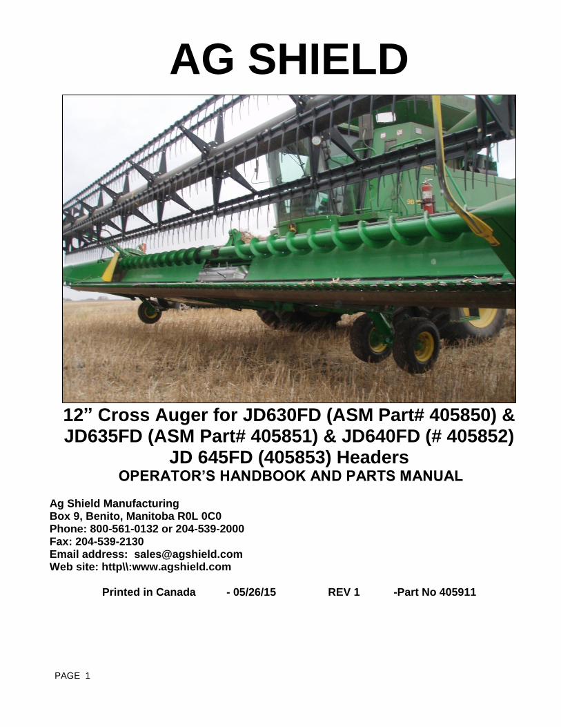
PAGE 1 AG SHIELD 12” Cross Auger for JD630FD (ASM Part# 405850) & JD635FD (ASM Part# 405851) & JD640FD (# 405852) JD 645FD (405853) Headers OPERATOR’S HANDBOOK AND PARTS MANUAL Ag Shield Manufacturing Box 9, Benito, Manitoba R0L 0C0 Phone: 800-561-0132 or 204-539-2000 Fax: 204-539-2130 Email address: [email protected] Web site: http\\:www.agshield.com Printed in Canada - 05/26/15 REV 1 -Part No 405911
Transcript of AG Shield Cross Auger Manual for John Deere JD630FD
PAGE 1
AG SHIELD
12” Cross Auger for JD630FD (ASM Part# 405850) & JD635FD (ASM Part# 405851) & JD640FD (# 405852)
JD 645FD (405853) Headers OPERATOR’S HANDBOOK AND PARTS MANUAL
Ag Shield Manufacturing Box 9, Benito, Manitoba R0L 0C0 Phone: 800-561-0132 or 204-539-2000 Fax: 204-539-2130 Email address: [email protected] Web site: http\\:www.agshield.com
Printed in Canada - 05/26/15 REV 1 -Part No 405911
PAGE 2
TABLE OF CONTENTS
1 INTRODUCTION AND SIGN-OFF FORM .................................................................................... 3 3 SAFETY ..................................................................................................................................... 4
3.1 SAFETY OVERVIEW ................................................................................................................... 5 3.2 GENERAL SAFETY .................................................................................................................... 5 3.2 MAINTENANCE SAFETY ............................................................................................................ 6 3.3 HYDRAULIC SAFETY ................................................................................................................. 6 3.4 SHEAR SAFETY ......................................................................................................................... 6 3.5 STORAGE SAFETY .................................................................................................................... 6 2.2 TRANSPORT SAFETY ................................................................................................................ 6 3.6 REFUELING SAFETY ................................................................................................................. 7 3.7 TIRE SAFETY .............................................................................................................................. 7 3.8 OPERATING SAFETY ................................................................................................................. 7 3.9 CROSS AUGER SAFETY ........................................................................................................... 7 3.10 SAFETY DECALS ....................................................................................................................... 8
4 SETUP FROM SHIPPING MODE .............................................................................................. 9
5 INSTALLATION ....................................................................................................................... 11 5.1 HYDRAULIC MOTOR SET UP .................................................................................................. 19 5.2 JD 640 FD CENTER MOUNT INSTALLATION ......................................................................... 20 5.3 STRIPPER BAR INSTALLATION.............................................................................................. 21
6 OPERATIONS ......................................................................................................................... 22 6.1 FIELD SETTING THE CROSS AUGER ..................................................................................... 22
7 PARTS ..................................................................................................................................... 23 7.1 405850 JD630FD & 405851 JD635FD AUGER PARTS OVERVIEW ........................................ 23 7.2 405852-405853 JD640FD 645FD-AUGER PARTS OVERVIEW ............................................... 24 7.3 FD SERIES RIGHT END DIRECT DRIVE .................................................................................. 25 7.4 LEFT END MOUNT- ALL MODELS .......................................................................................... 26 7.5 CENTER MOUNT FOR MODEL 635-630FD ............................................................................. 27 7.6 CENTER MOUNT FOR MODEL 640FD-645FD ......................................................................... 28
8 WARRANTY ............................................................................................................................ 29

PAGE 3
1 INTRODUCTION AND SIGN-OFF FORM
Congratulations! on your choice of an Ag Shield cross auger. This equipment has been designed and
manufactured to meet the harvesting needs of the discerning farmers and custom harvesters.
OPERATOR ORIENTATION - The directions left, right, front and rear, as mentioned throughout this manual,
are as seen from the tractor driver's seat and facing in the normal direction of travel. Ag Shield follows the general safety standards specified by the American Society of Agricultural Engineers (ASAE) and the Occupational Safety and Health Administration OSHA). Anyone who will be operating and/or maintaining the Ag Shield Yield Shield must read and clearly understand ALL Safety, Operating, and Maintenance information presented in this manual. Do not operate or allow anyone else to operate this equipment until such information has been reviewed. Review this information annually before season start-up. Make these reviews of safety and operation a standard practice for all of your equipment. An untrained operator is not qualified to operate this machine. A sign off sheet is provided for your record keeping to show that all personnel who will be working with the equipment have read and understood the information in the Operators Handbook and have been instructed in the operation of the equipment.
SIGN-OFF FORM
DATE OPERATORS SIGNATURE EMPLOYERS SIGNATURE
4
3 SAFETY
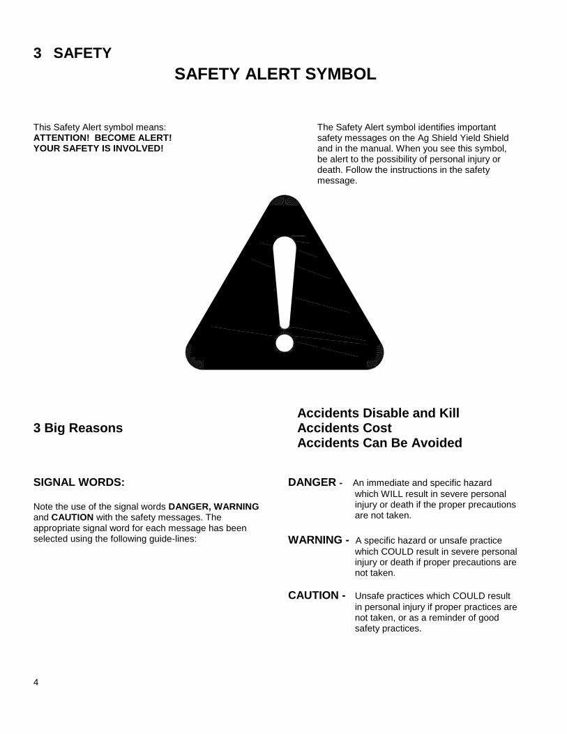
SAFETY ALERT SYMBOL
This Safety Alert symbol means: ATTENTION! BECOME ALERT! YOUR SAFETY IS INVOLVED!
The Safety Alert symbol identifies important safety messages on the Ag Shield Yield Shield and in the manual. When you see this symbol, be alert to the possibility of personal injury or death. Follow the instructions in the safety message.
Accidents Disable and Kill 3 Big Reasons Accidents Cost
Accidents Can Be Avoided
SIGNAL WORDS: Note the use of the signal words DANGER, WARNING and CAUTION with the safety messages. The appropriate signal word for each message has been selected using the following guide-lines:
DANGER - An immediate and specific hazard
which WILL result in severe personal injury or death if the proper precautions are not taken.
WARNING - A specific hazard or unsafe practice
which COULD result in severe personal injury or death if proper precautions are not taken.
CAUTION - Unsafe practices which COULD result
in personal injury if proper practices are not taken, or as a reminder of good safety practices.
5
3.1 SAFETY OVERVIEW YOU are responsible for the SAFE operation and maintenance of your Ag Shield cross auger. YOU must ensure that you and anyone else who is going to operate, maintain or work around the cross auger be familiar with the operating and maintenance procedures and related SAFETY information contained in this manual. This manual will take you step-by-step through your working day and alerts you to all good safety practices that should be adhered to while operating the cross auger.
Remember, YOU are the key to safety. Good safety practices not only protect you but also the people around you. Make these practices a working part of your safety program. Be certain that EVERYONE operating this equipment is familiar with the recommended operating and maintenance procedures and follows all the safety precautions. Most accidents can be prevented. Do not risk injury or death by ignoring good safety practices.
Cross auger owners must give operating instruc-
tions to operators or employees before allowing them to operate the cross auger, and at least annually thereafter per OSHA regulation 1928.57.
The most important safety device on this
equipment is a SAFE operator. It is the operator's responsibility to read and understand ALL Safety and Operating instructions in the manual and to follow these. All accidents can be avoided.
A person who has not read and understood all
operating and safety instructions is not qualified to operate the machine. An untrained operator exposes himself and bystanders to possible serious injury or death.
Do not modify the equipment in any way.
Unauthorized modification may impair the function and/or safety and could affect the life of the equipment.
Think SAFETY! Work SAFELY!
3.2 GENERAL SAFETY 1. Read and understand the
Operator's Manual and all safety signs before operating, maintaining, adjusting the Yield Shield.
2. Only trained competent persons shall operate the
reconditioner. An untrained operator is not qualified to operate the machine.
3. Have a first-aid kit
available for use should the need arise and know how to use it.
4. Have a fire extinguisher
available for use should the need arise and know how to use it.
5. Do not allow riders.
6. Wear appropriate
protective gear. This list includes but is not limited to:
A hard hat
Protective shoes with slip resistant soles
Protective glasses or goggles
Heavy gloves
Hearing protection
7. Stop the engine, place all controls in neutral, set
park brake, remove ignition key and wait for all moving parts to stop before servicing, adjusting, repairing or unplugging.
8. Review safety related items with all personnel
annually.
2
2.
4.
6.

6
3.2 MAINTENANCE SAFETY 1. Review the Operators Manual and all safety items
before working with, maintaining or operating the Yield Shield.
2. Stop the tractor engine, place all controls in
neutral, set park brake, remove ignition key, wait for all moving pads to stop before servicing, adjusting, or repairing.
3. Before applying pressure to a hydraulic system,
make sure all components are tight and that steel lines, hoses and couplings are not damaged.
4. Relieve pressure from hydraulic circuit before
servicing or disconnecting from tractor.
5. Keep hands, feet, clothing and hair away from all
moving and/or rotating parts.
6. Clear the area of bystanders, especially children,
when carrying out any maintenance and repairs or making any adjustments.
7. Place stands or blocks under the frame before
working beneath the machine.
3.3 HYDRAULIC SAFETY 1. Always place all tractor hydraulic controls in
neutral before dismounting. 2. Make sure that all components in the hydraulic
system are kept in good condition and are clean.
3. Replace any worn, cut, abraded, flattened or
crimped hoses and steel lines.
4. Do not attempt any makeshift repairs to the
hydraulic lines, fittings or hoses by using tape, clamps or cements. The hydraulic system operates under extremely high-pressure. Such repairs will fail suddenly and create a hazardous and unsafe condition.
5. Wear proper hand and eye protection when
searching for a high-pressure hydraulic leak. Use a piece of wood or cardboard as a backstop instead of hands to isolate and identify a leak.
6. If injured by a concentrated high-pressure stream
of hydraulic fluid, seek medical attention immediately. Serious infection or toxic reaction can develop from hydraulic fluid piercing the skin surface.
7. Before applying pressure to hydraulic system
make sure that all connections are tight and that all hoses and fittings are in good condition.
3.4 SHEAR SAFETY The operator must obey all safety labels. 1. Keep operators and bystanders away from all
moving parts. 2. Shut off tractor engine and remove key before
coming close to the implement or doing any maintenance
3. Never service or unplug shears while they are running, a single slip and you could be badly hurt or killed.
3.5 STORAGE SAFETY
1. Store unit in an area away from human activity.
2. Do not permit children to play on or around the
stored Yield Shield.
2.2 TRANSPORT SAFETY
1. Read and understand ALL the information in the Operator's Manual regarding procedures and SAFETY when operating the Yield Shield in the field and/or on the road.
2. Check with local authorities regarding machinery
transport on public roads. Obey all applicable laws and regulations.
3. Always travel at a safe speed. Use caution when
making corners or meeting traffic.
4. Make sure the SMV (Slow Moving Vehicle)
emblem and all the lights and reflectors that are required by the local highway and transport authorities are in place, are clean and can be seen clearly by all overtaking and oncoming traffic. Daybreak and dusk are particularly dangerous and pilot vehicles are recommended.
7
5. Ensure that the trailer is hitched positively to the towing vehicle. Always use a safety chain between the trailer and the tractor.
6. Keep to the right and yield the right-of-way to allow
faster traffic to pass. Drive on the road shoulder, if permitted by law.
7. Always use hazard warning flashers on the Yield
Shield when transporting unless prohibited by law.
3.6 REFUELING SAFETY 1. Handle fuel with care. It is highly flammable.
2. Do not refuel the machine while smoking or when near open flame or sparks. 3. Stop engine before refueling.
Clean up spilled fuel before restarting engine.
3.7 TIRE SAFETY 1. Failure to follow proper procedures when
mounting a tire on a wheel or rim can produce an explosion, which may result in serious injury or death.
2. Do not attempt to mount a tire unless you have the
proper equipment and experience to do the job. 3. Have a qualified tire dealer or repair service
perform required tire maintenance. 4. Operate the tires at the pressures, loads, and
speeds suggested by the manufacturer.
3.8 OPERATING SAFETY 1. Read and understand the Operator’s Manual and
all safety signs before using. 2. Stop engine place all controls in neutral, set park
brake, remove ignition key, wait for all moving parts to stop before servicing, adjusting, repairing or unplugging.
3. Before conditioning a field, be familiar with all
potential hazards: trees, rocks ditches, gullies, etc. Plan your route to avoid hazards. Keep Yield Shield width in mind when maneuvering to avoid obstacles.
4. Keep hands, feet, hair and clothing away from all moving and/or rotating parts.
5. Keep all shields and guards in place when
operating. 6. Do not allow riders on the Yield Shield or tractor
during operation or transporting. 7. Clear the area of all bystanders, especially
children, before starting. 8. Stay away from machine when folding deflectors.
Keep others away. 9. Before applying pressure to the hydraulic system,
make sure all components are tight and that steel lines, hoses and couplings are not damaged.
10. Review safety instructions annually
3.9 CROSS AUGER SAFETY The cross auger has sufficient power to sever limbs and cause serious to fatal injury. Always stop the cross auger before dismounting. Always be certain that no one is in front of combine header Shield before engaging the auger drive. When greasing the auger, do so with the combine motor shut off and the park brake securely set. Never attempt to help the crop move along the canvases with a wrench or other item that might get into the auger and draw the wrench holder into the auger.
8
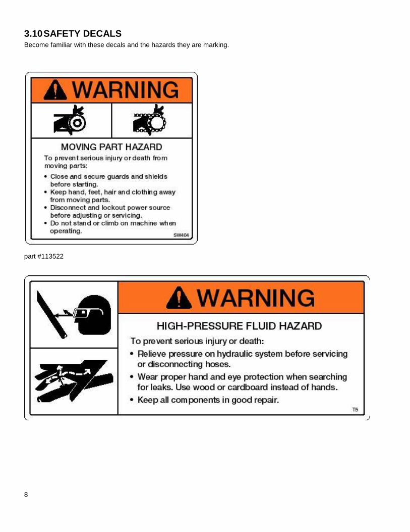
3.10 SAFETY DECALS Become familiar with these decals and the hazards they are marking.
part #113522
1.
9
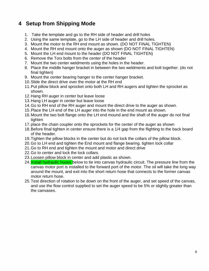
4 Setup from Shipping Mode
1. Take the template and go to the RH side of header and drill holes 2. Using the same template, go to the LH side of header and drill holes. 3. Mount the motor to the RH end mount as shown. (DO NOT FINAL TIGHTEN) 4. Mount the RH end mount onto the auger as shown (DO NOT FINAL TIGHTEN) 5. Mount the LH end mount to the header (DO NOT FINAL TIGHTEN) 6. Remove the Torx bolts from the center of the header 7. Mount the two center weldments using the holes in the header. 8. Place the middle hanger bracket in between the two weldments and bolt together. (do not
final tighten) 9. Mount the center bearing hanger to the center hanger bracket. 10. Slide the direct drive over the motor at the RH end 11. Put pillow block and sprocket onto both LH and RH augers and tighten the sprocket as
shown. 12. Hang RH auger in center but leave loose 13. Hang LH auger in center but leave loose 14. Go to RH end of the RH auger and mount the direct drive to the auger as shown. 15. Place the LH end of the LH auger into the hole in the end mount as shown. 16. Mount the two bolt flange onto the LH end mound and the shaft of the auger do not final
tighten 17. place the chain coupler onto the sprockets for the center of the auger as shown 18. Before final tighten in center ensure there is a 1/4 gap from the flighting to the back board
of the header. 19. Tighten the pillow blocks in the center but do not lock the collars of the pillow block. 20. Go to LH end and tighten the End mount and flange bearing. tighten lock collar 21. Go to RH end and tighten the mount and motor and direct drive 22. Go to center and lock the lock collars. 23. Loosen pillow block in center and add plastic as shown. 24. Install hydraulic hoses below to tie into canvas hydraulic circuit. The pressure line from the
canvas motor port is installed to the forward port of the motor. The oil will take the long way around the mount, and exit into the short return hose that connects to the former canvas motor return hose.
25. Test direction of rotation to be down on the front of the auger, and set speed of the canvas, and use the flow control supplied to set the auger speed to be 5% or slightly greater than the canvases.
10
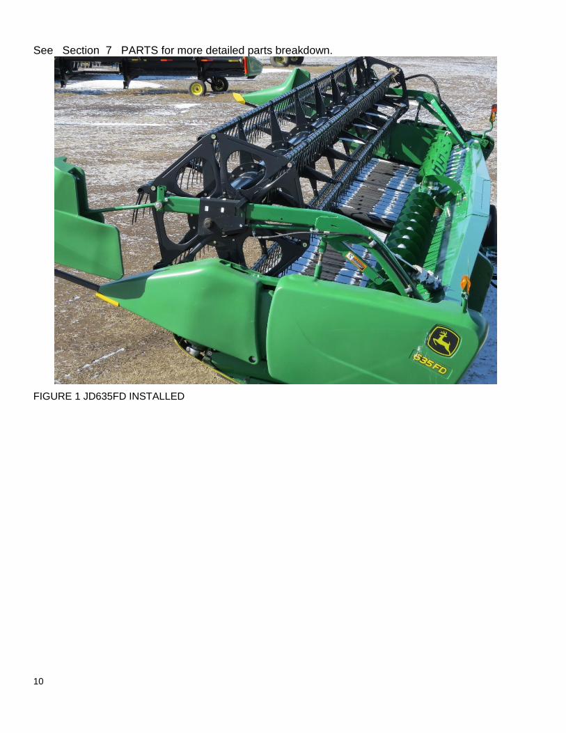
See Section 7 PARTS for more detailed parts breakdown.
FIGURE 1 JD635FD INSTALLED
11
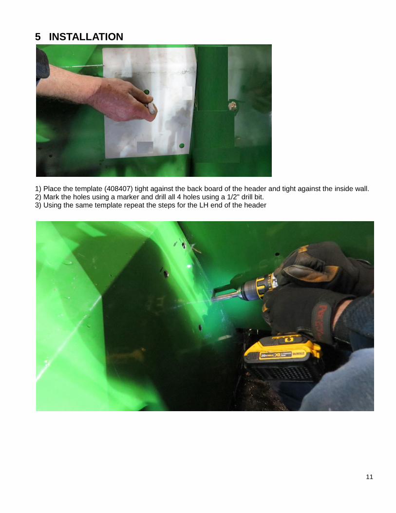
5 INSTALLATION
1) Place the template (408407) tight against the back board of the header and tight against the inside wall. 2) Mark the holes using a marker and drill all 4 holes using a 1/2" drill bit. 3) Using the same template repeat the steps for the LH end of the header
12
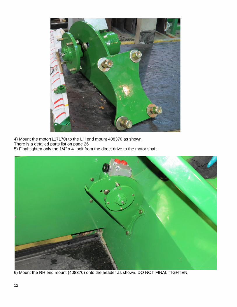
4) Mount the motor(117170) to the LH end mount 408370 as shown. There is a detailed parts list on page 26 5) Final tighten only the 1/4" x 4" bolt from the direct drive to the motor shaft.
6) Mount the RH end mount (408370) onto the header as shown. DO NOT FINAL TIGHTEN.
13
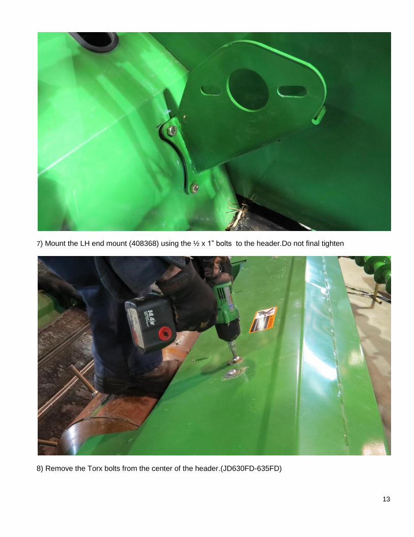
7) Mount the LH end mount (408368) using the ½ x 1” bolts to the header.Do not final tighten
8) Remove the Torx bolts from the center of the header.(JD630FD-635FD)
14
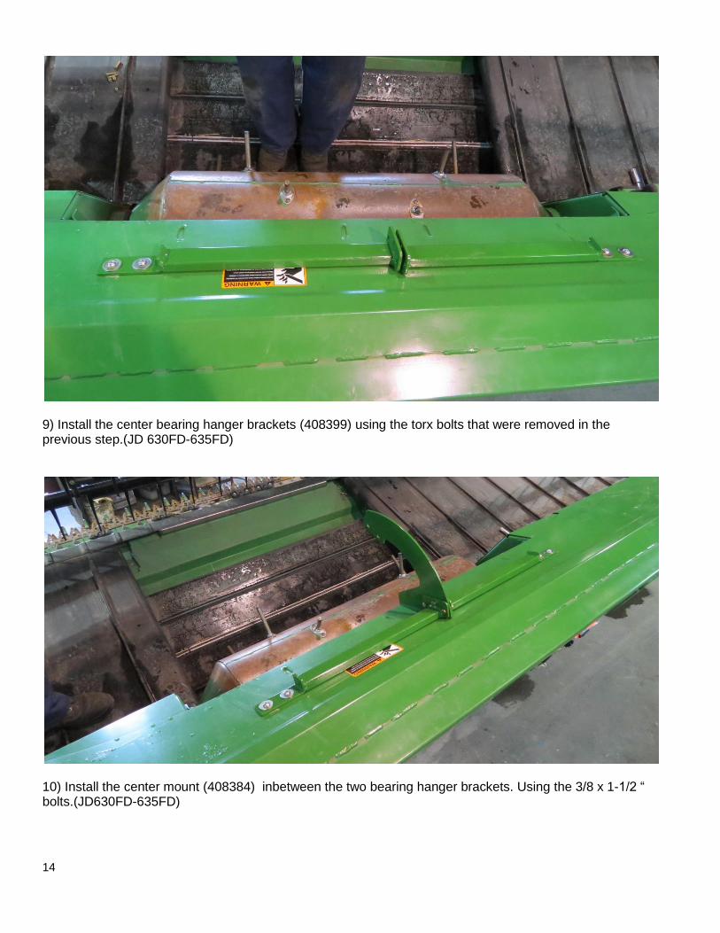
9) Install the center bearing hanger brackets (408399) using the torx bolts that were removed in the previous step.(JD 630FD-635FD)
10) Install the center mount (408384) inbetween the two bearing hanger brackets. Using the 3/8 x 1-1/2 “ bolts.(JD630FD-635FD)
15
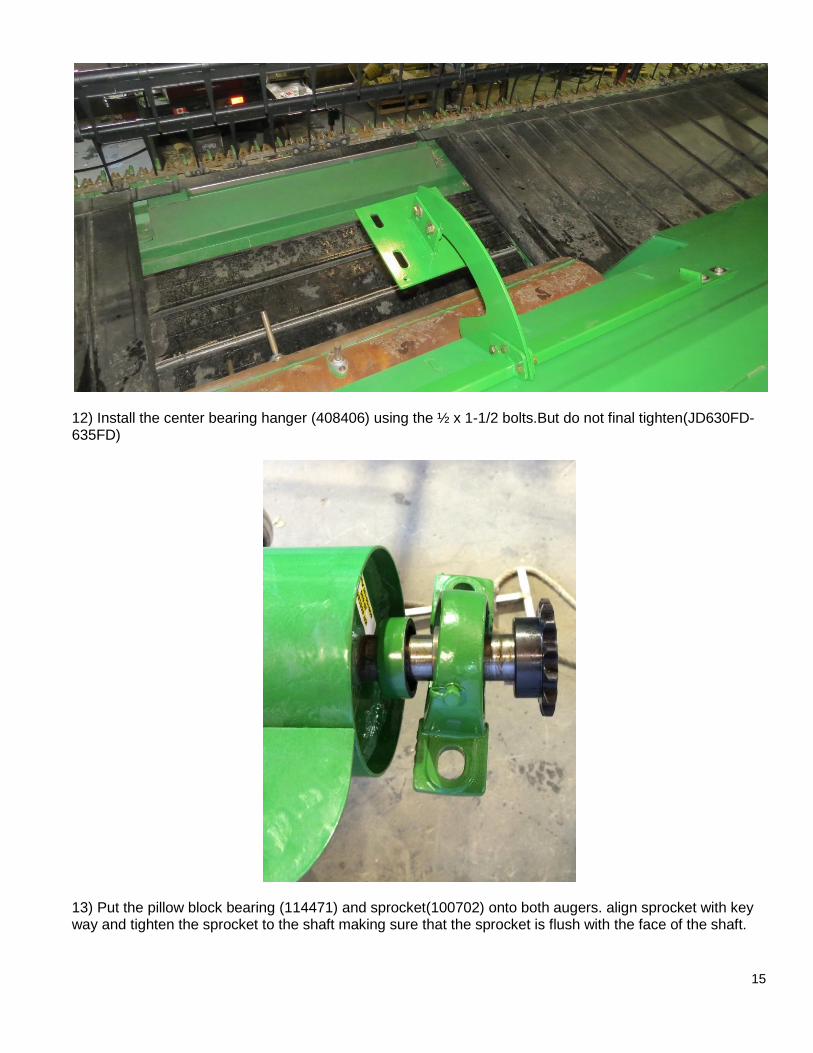
12) Install the center bearing hanger (408406) using the ½ x 1-1/2 bolts.But do not final tighten(JD630FD-635FD)
13) Put the pillow block bearing (114471) and sprocket(100702) onto both augers. align sprocket with key way and tighten the sprocket to the shaft making sure that the sprocket is flush with the face of the shaft.
16
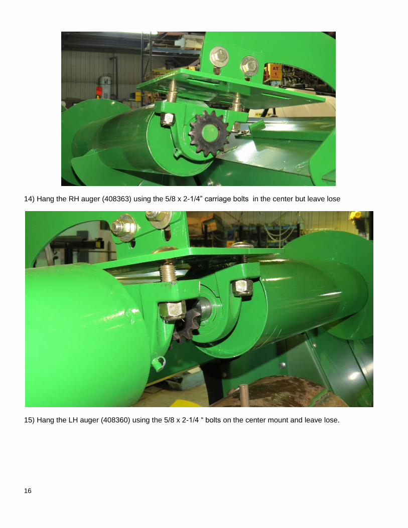
14) Hang the RH auger (408363) using the 5/8 x 2-1/4” carriage bolts in the center but leave lose
15) Hang the LH auger (408360) using the 5/8 x 2-1/4 “ bolts on the center mount and leave lose.

17
16) Mount the RH end of the the RH auger onto the direct drive (407105) using the 3/8 x 1-1/4 bolts and 3/8 lock washers. Tighten snug but do not final tighten.
17) Go the the LH end and slide the auger shaft through the end mount hole, Mount the flange bearing (114483) onto the shaft and bolt it to the end mount. Using the ½ x 2 carriage bolt tighten snug but do not final tighten.
18
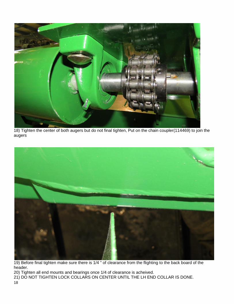
18) Tighten the center of both augers but do not final tighten, Put on the chain coupler(114469) to join the augers
19) Before final tighten make sure there is 1/4 " of clearance from the flighting to the back board of the header. 20) Tighten all end mounts and bearings once 1/4 of clearance is acheived. 21) DO NOT TIGHTEN LOCK COLLARS ON CENTER UNTIL THE LH END COLLAR IS DONE.
19
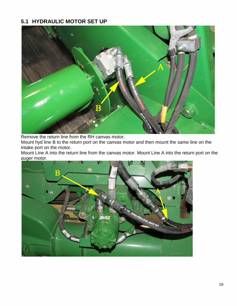
5.1 HYDRAULIC MOTOR SET UP
Remove the return line from the RH canvas motor. Mount hyd line B to the return port on the canvas motor and then mount the same line on the intake port on the motor. Mount Line A into the return line from the canvas motor. Mount Line A into the return port on the auger motor.

20
5.2 JD 640 FD CENTER MOUNT INSTALLATION
JD640FD has a center reel mount in the middle of the header. The reel mount arm is held in place with a 1” pin. The red piece shown in the picture above will be green. As well as the grey piece as well.
1) Undo the bolt that is holding the pin in place for the center reel mount
2) Begin to pound out the pin until the “red part 408476” can slide in place.
3) Pound the pin back to original spot but not all the way, just enough so that the pin holds the red piece in
place. If the pin is to short, use the 1" bolt provided in the kit.
4) Slide the “grey piece 408489” over the 1” pin and bolt it to the red part using the 3/8” bolts.
5) Put bolt back into pin and tighten bolt.
This is a view from behind the header. The two small grey tabs shown will keep the center mount from
trying to lift up. The hole is cut off center to allow a different length each 90 degrees of rotation.
These tabs will mount through the “red piece” and the small over hang from the header.
21
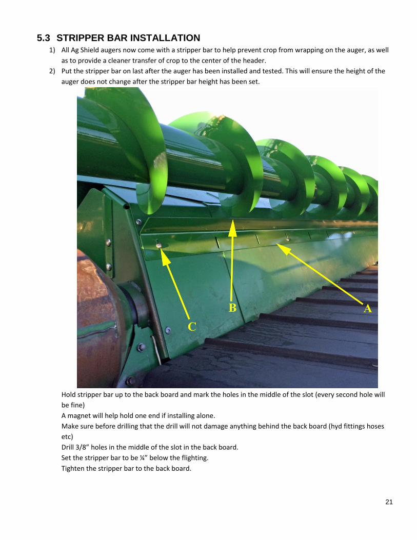
5.3 STRIPPER BAR INSTALLATION 1) All Ag Shield augers now come with a stripper bar to help prevent crop from wrapping on the auger, as well
as to provide a cleaner transfer of crop to the center of the header.
2) Put the stripper bar on last after the auger has been installed and tested. This will ensure the height of the
auger does not change after the stripper bar height has been set.
Hold stripper bar up to the back board and mark the holes in the middle of the slot (every second hole will
be fine)
A magnet will help hold one end if installing alone.
Make sure before drilling that the drill will not damage anything behind the back board (hyd fittings hoses
etc)
Drill 3/8” holes in the middle of the slot in the back board.
Set the stripper bar to be ¼” below the flighting.
Tighten the stripper bar to the back board.
22
6 OPERATIONS
DANGER Stay clear of auger whenever it is running
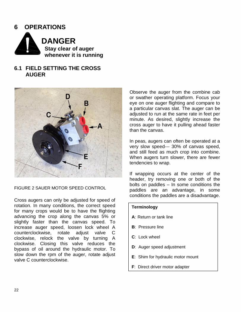
6.1 FIELD SETTING THE CROSS AUGER
FIGURE 2 SAUER MOTOR SPEED CONTROL
Cross augers can only be adjusted for speed of rotation. In many conditions, the correct speed for many crops would be to have the flighting advancing the crop along the canvas 5% or slightly faster than the canvas speed. To increase auger speed, loosen lock wheel A counterclockwise, rotate adjust valve C clockwise, relock the valve by turning A clockwise. Closing this valve reduces the bypass of oil around the hydraulic motor. To slow down the rpm of the auger, rotate adjust valve C counterclockwise.
Observe the auger from the combine cab or swather operating platform. Focus your eye on one auger flighting and compare to a particular canvas slat. The auger can be adjusted to run at the same rate in feet per minute. As desired, slightly increase the cross auger to have it pulling ahead faster than the canvas. In peas, augers can often be operated at a very slow speed--- 30% of canvas speed, and still feed as much crop into combine. When augers turn slower, there are fewer tendencies to wrap. If wrapping occurs at the center of the header, try removing one or both of the bolts on paddles – In some conditions the paddles are an advantage, in some conditions the paddles are a disadvantage.
Terminology A: Return or tank line B: Pressure line C: Lock wheel D: Auger speed adjustment E: Shim for hydraulic motor mount F: Direct driver motor adapter

23
7 PARTS
7.1 405850 JD630FD & 405851 JD635FD AUGER PARTS OVERVIEW
DETAIL A
DETAIL B
DETAIL C
A
B
C
ITEM QTY PART NUMBER
1 1 408360 JD635FD auger wldt LH dir drv
2 1 408363 JD635FD auger wldt RH dirdrv
3 1 114483 Bearing 1.25 in FL207 2 bolt
flat flg
4 1 408368 JD 635FD Auger Mnt Wldt
5 1 407105 direct drive motor adapter wldt
6 1 407271 shim hyd motor mt AGCO
9250
ITEM QTY PART NUMBER
7 1 117170 motor with flow control 5.9
danfoss
8 1 408370 JD 635FD Auger RH Mnt Wldt
9 2 408399 JD635FD center mount tube
10 1 408384 JD 635 FD center hanger
bracket
11 1 408406 JD 635 FD CENTER BRNG
WLDT
12 1 408408 JD 635FD plastic guard
JD 635FD OVERVIEW
9
9
11
12
10
2
1
8
7
2
1
3
4
6
5

24
7.2 405852-405853 JD640FD 645FD-AUGER PARTS OVERVIEW
DETAIL A
DETAIL B
DETAIL C
A
B
C
ITEM QTY PART NUMBER
1 1 408370 JD 635FD Auger RH Mnt Wldt
2 1 408368 JD 635FD Auger Mnt Wldt
3 1 408470 JD640FD auger wldt RH dirdrv
4 1 408473 JD640FD auger wldt LH dir drv
5 1 117170 motor with flow control 5.9
danfoss
6 1 407271 shim hyd motor mt AGCO
9250
7 1 407105 direct drive motor adapter wldt
8 1 114483 Bearing 1.25 in FL207 2 bolt
flat flg
9 1 408476 JD64x Center mount wldt
10 1 408408 JD 635FD plastic guard
11 1 100956 bolt 1nc x 11 gr8 pltd
12 1 408490 JD 640 center mount slot tab
11
9
12
10
4
3
5 1 6 7 3
8
42
640FDOVERVIEW
25
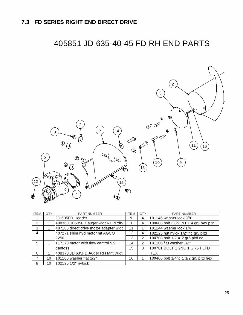
7.3 FD SERIES RIGHT END DIRECT DRIVE
ITEM QTY PART NUMBER
1 1 JD 635FD Header
2 1 408363 JD635FD auger wldt RH dirdrv
3 1 407105 direct drive motor adapter wldt
4 1 407271 shim hyd motor mt AGCO
9250
5 1 117170 motor with flow control 5.9
danfoss
6 1 408370 JD 635FD Auger RH Mnt Wldt
7 10 101106 washer flat 1/2"
8 10 102125 1/2" nylock
ITEM QTY PART NUMBER
9 4 101145 washer lock 3/8"
10 4 100603 bolt 3 8NCx1 1 4 gr5 hex pltd
11 1 101144 washer lock 1/4
12 4 102125 nut nylok 1/2" nc gr5 pltd
13 2 100703 bolt 1-2 X 2 gr5 pltd nc
14 2 101106 flat washer 1/2"
15 8 100701 BOLT 1 2NC 1 GR5 PLTD
HEX
16 1 100405 bolt 1/4nc 1 1/2 gr5 pltd hex
405851 JD 635-40-45 FD RH END PARTS
12
5
4
15
68
7
14
13
10 9
3
11 16
2

26
7.4 LEFT END MOUNT- ALL MODELS
PART NUMBERQTYITEM
408360 JD635FD auger wldt LH dir drv11
114483 Bearing 1.25 in FL207 2 bolt
flat flg
12
408368 JD 635FD Auger Mnt Wldt13
101106 washer flat 1/2"104
102125 1/2" nylock105
102125 nut nylok 1/2" nc gr5 pltd46
100943 carriage bolt 1-2 X 2 NC27
100701 BOLT 1 2NC 1 GR5 PLTD
HEX
88
100405 bolt 1/4nc 1 1/2 gr5 pltd hex19
1
5
4
8
7
2
6
3
JD 630 -35-40-45 FD LEFT END
27
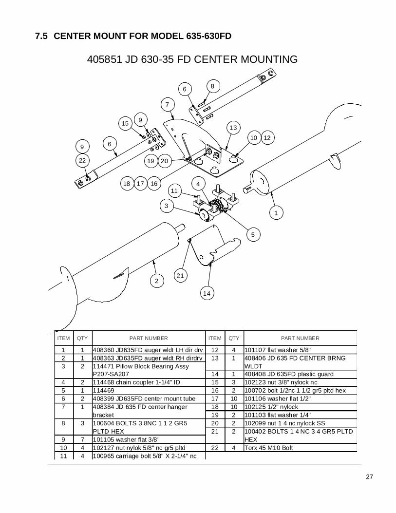
7.5 CENTER MOUNT FOR MODEL 635-630FD
ITEM QTY PART NUMBER
1 1 408360 JD635FD auger wldt LH dir drv
2 1 408363 JD635FD auger wldt RH dirdrv
3 2 114471 Pillow Block Bearing Assy
P207-SA207
4 2 114468 chain coupler 1-1/4" ID
5 1 114469
6 2 408399 JD635FD center mount tube
7 1 408384 JD 635 FD center hanger
bracket
8 3 100604 BOLTS 3 8NC 1 1 2 GR5
PLTD HEX
9 7 101105 washer flat 3/8"
10 4 102127 nut nylok 5/8" nc gr5 pltd
11 4 100965 carriage bolt 5/8" X 2-1/4" nc
ITEM QTY PART NUMBER
12 4 101107 flat washer 5/8"
13 1 408406 JD 635 FD CENTER BRNG
WLDT
14 1 408408 JD 635FD plastic guard
15 3 102123 nut 3/8" nylock nc
16 2 100702 bolt 1/2nc 1 1/2 gr5 pltd hex
17 10 101106 washer flat 1/2"
18 10 102125 1/2" nylock
19 2 101103 flat washer 1/4"
20 2 102099 nut 1 4 nc nylock SS
21 2 100402 BOLTS 1 4 NC 3 4 GR5 PLTD
HEX
22 4 Torx 45 M10 Bolt
405851 JD 630-35 FD CENTER MOUNTING
2
14
13
11
5
4
13
10 126
22
9
915
7
6 8
161718
2019
21
28
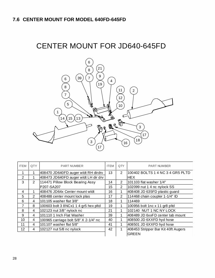
7.6 CENTER MOUNT FOR MODEL 640FD-645FD
ITEM QTY PART NUMBER
1 1 408470 JD640FD auger wldt RH dirdrv
2 1 408473 JD640FD auger wldt LH dir drv
3 2 114471 Pillow Block Bearing Assy
P207-SA207
4 1 408476 JD64x Center mount wldt
5 2 408488 center mount lock plas
6 4 101105 washer flat 3/8"
7 8 100603 bolt 3 8NCx1 1 4 gr5 hex pltd
8 4 102123 nut 3/8" nylock nc
9 4 101110 1 Inch Flat Washer
10 4 100965 carriage bolt 5/8" X 2-1/4" nc
11 4 101107 washer flat 5/8"
12 4 102127 nut 5/8 nc nylock
ITEM QTY PART NUMBER
13 2 100402 BOLTS 1 4 NC 3 4 GR5 PLTD
HEX
14 2 101103 flat washer 1/4"
15 2 102099 nut 1 4 nc nylock SS
16 1 408408 JD 635FD plastic guard
17 2 114468 chain coupler 1-1/4" ID
18 1 114469
19 1 100956 bolt 1nc x 11 gr8 pltd
21 1 102140 NUT 1 NC NY LOCK
39 1 408489 JD 6xxFD center tab mount
40 1 408500 JD 6XXFD hyd hose
41 1 408501 JD 6XXFD hyd hose
42 1 408453 Stripper Bar Kit 40ft Augers
GREEN
5
1
2
419
9
21
16
3
17
18
17
3
131514
10
12
11
7
8
6
CENTER MOUNT FOR JD640-645FD
39 7
8
6
29
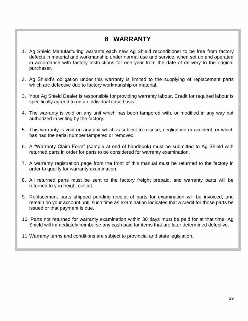
8 WARRANTY
1. Ag Shield Manufacturing warrants each new Ag Shield reconditioner to be free from factory defects in material and workmanship under normal use and service, when set up and operated in accordance with factory instructions for one year from the date of delivery to the original purchaser.
2. Ag Shield’s obligation under this warranty is limited to the supplying of replacement parts
which are defective due to factory workmanship or material. 3. Your Ag Shield Dealer is responsible for providing warranty labour. Credit for required labour is
specifically agreed to on an individual case basis. 4. The warranty is void on any unit which has been tampered with, or modified in any way not
authorized in writing by the factory. 5. This warranty is void on any unit which is subject to misuse, negligence or accident, or which
has had the serial number tampered or removed. 6. A “Warranty Claim Form” (sample at end of handbook) must be submitted to Ag Shield with
returned parts in order for parts to be considered for warranty examination. 7. A warranty registration page from the front of this manual must be returned to the factory in
order to qualify for warranty examination. 8. All returned parts must be sent to the factory freight prepaid, and warranty parts will be
returned to you freight collect. 9. Replacement parts shipped pending receipt of parts for examination will be invoiced, and
remain on your account until such time as examination indicates that a credit for those parts be issued or that payment is due.
10. Parts not returned for warranty examination within 30 days must be paid for at that time. Ag
Shield will immediately reimburse any cash paid for items that are later determined defective. 11. Warranty terms and conditions are subject to provincial and state legislation.

35
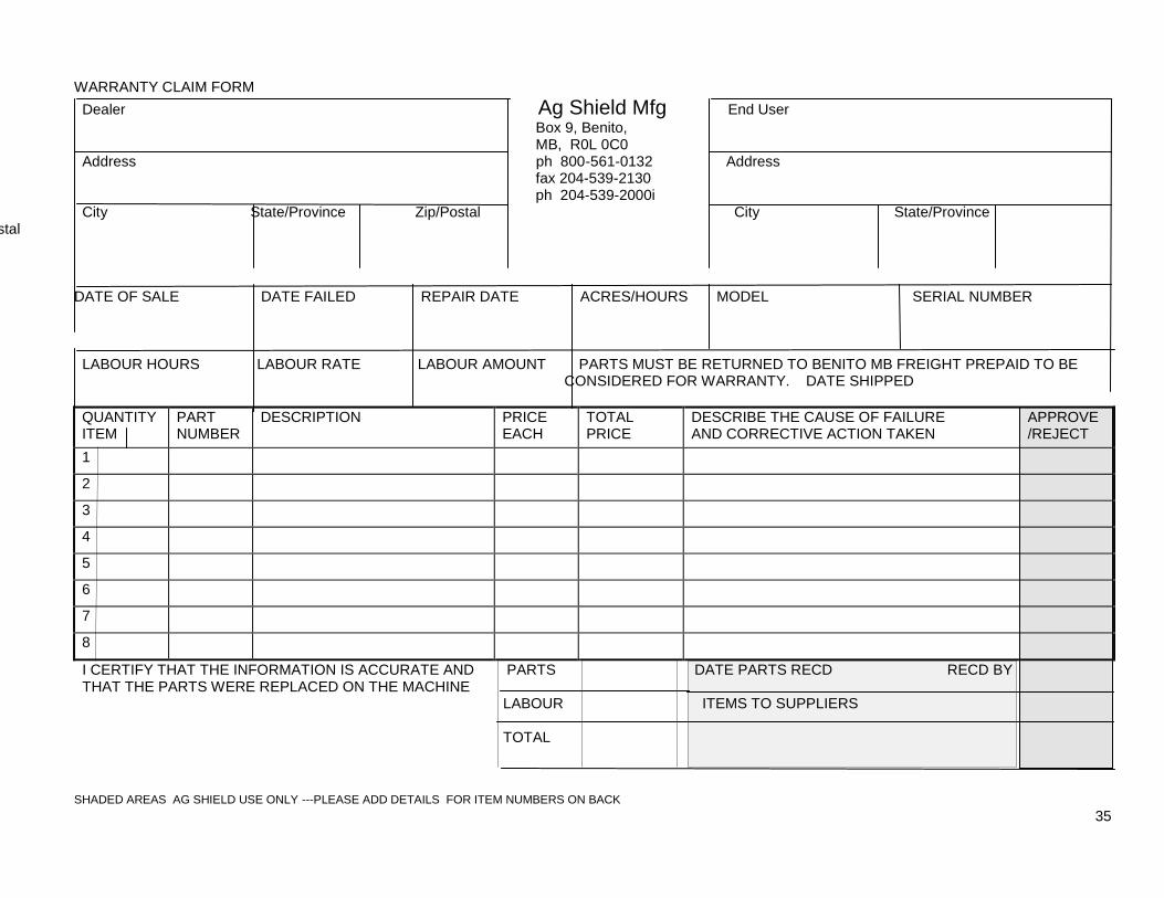
WARRANTY CLAIM FORM
Dealer Ag Shield Mfg End User
Box 9, Benito, MB, R0L 0C0 Address ph 800-561-0132 Address fax 204-539-2130 ph 204-539-2000i City State/Province Zip/Postal City State/Province
Zip/Postal DATE OF SALE DATE FAILED REPAIR DATE ACRES/HOURS MODEL SERIAL NUMBER LABOUR HOURS LABOUR RATE LABOUR AMOUNT PARTS MUST BE RETURNED TO BENITO MB FREIGHT PREPAID TO BE CONSIDERED FOR WARRANTY. DATE SHIPPED
QUANTITY ITEM
PART NUMBER
DESCRIPTION PRICE EACH
TOTAL PRICE
DESCRIBE THE CAUSE OF FAILURE AND CORRECTIVE ACTION TAKEN
APPROVE /REJECT
1
2
3
4
5
6
7
8
I CERTIFY THAT THE INFORMATION IS ACCURATE AND PARTS DATE PARTS RECD RECD BY THAT THE PARTS WERE REPLACED ON THE MACHINE LABOUR ITEMS TO SUPPLIERS TOTAL SHADED AREAS AG SHIELD USE ONLY ---PLEASE ADD DETAILS FOR ITEM NUMBERS ON BACK

36
ITEM ITEM The end