4. 7.3 Dielectric breakdown
43
www.binils.com for Anna University | Polytechnic and Schools Download Binils Android App in Playstore Download Photoplex App 4. 7.3 Dielectric breakdown When a dielectric is placed in an electric field and when the field exceeds the critical field, the dielectric loses its insulation property and becomes conduction. This phenomenon is known as dielectric breakdown. Dielectric strength The electrical field strength at which dielectric breakdown occurs is known as dielectric strength. It is the breakdown voltage per unit thickness of the material The dielectric strength = ℎ There are different mechanisms by which the dielectric breakdown takes place. Some of the types of breakdown are 1. Intrinsic (or) avalanche breakdown 2. Thermal breakdown 3. Chemical and electrochemical breakdown 4. Discharge breakdown 5. Defect breakdown 1. Intrinsic (or) avalanche breakdown When a dielectric is subjected to electric field then the electrons in the valance band acquire sufficient energy, go to conduction band by crossing the energy gap, and hence become conducting electrons. Therefore, large current flows and is called Intrinsic (or) Zener breakdown Avalanche breakdown These conduction electrons on further application of field collide with the valence electrons, which are involved in the covalent bonds and remove more electrons hence transferring them as conduction electrons. This process continues as a chain reaction.
Transcript of 4. 7.3 Dielectric breakdown
www.binils.com for Anna University | Polytechnic and Schools
Download Binils Android App in Playstore Download Photoplex App
4. 7.3 Dielectric breakdown
When a dielectric is placed in an electric field and when the field exceeds the
critical field, the dielectric loses its insulation property and becomes conduction. This
phenomenon is known as dielectric breakdown.
Dielectric strength
The electrical field strength at which dielectric breakdown occurs is known as
dielectric strength. It is the breakdown voltage per unit thickness of the material
The dielectric strength = 𝐷𝑖𝑒𝑙𝑒𝑐𝑡𝑟𝑖𝑐 𝑣𝑜𝑙𝑡𝑎𝑔𝑒 𝑇ℎ𝑖𝑐𝑘𝑛𝑒𝑠𝑠 𝑜𝑓 𝑑𝑖𝑒𝑙𝑒𝑐𝑡𝑟𝑖𝑐
There are different mechanisms by which the dielectric breakdown takes place.
Some of the types of breakdown are
1. Intrinsic (or) avalanche breakdown
2. Thermal breakdown
3. Chemical and electrochemical breakdown
4. Discharge breakdown
5. Defect breakdown
1. Intrinsic (or) avalanche breakdown
When a dielectric is subjected to electric field then the electrons in the valance
band acquire sufficient energy, go to conduction band by crossing the energy gap, and
hence become conducting electrons. Therefore, large current flows and is called
Intrinsic (or) Zener breakdown
Avalanche breakdown
These conduction electrons on further application of field collide with the valence
electrons, which are involved in the covalent bonds and remove more electrons hence
transferring them as conduction electrons. This process continues as a chain reaction.
www.binils.com for Anna University | Polytechnic and Schools
Download Binils Android App in Playstore Download Photoplex App
Therefore, very large current flows through the dielectric and hence called avalanche
breakdown
Characteristics
1. It can occur even at lower temperatures
2. It requires relatively large electric fields
3. This kind of breakdowns occurs in thin samples
4. It does not depends on the electrodes and shape of
the material.
5. It occurs within a short span of time (milliseconds)
2. Thermal Breakdown
When a dielectric is subjected to an electrical field, heat is generated. The
generated heat is dissipated by the dielectric. In some cases, the heat generated will be
very high compared to the heat dissipated. Under such conditions, the temperature
inside the dielectric increases which results in local melting. Once melting starts, that
particular region becomes highly conduction. So enormous current flows through the
material and dielectric breakdown occurs
Characteristics
1. It can occur even at higher temperatures
2. It requires moderate electric fields
3. It depends on the size and shape of the dielectric material
4. Since the dielectric loss is proportional to frequency, the breakdown occurs at
relatively lower field strength
5. It occurs in the order of milli seconds
3. Chemical and electrochemical breakdown
This type of breakdown is almost similar to the thermal breakdown. If the
temperature increases, mobility of the ions will increase. When mobility increases,
leakage current also increases and hence the electro chemical reaction may be induced
to take place.
www.binils.com for Anna University | Polytechnic and Schools
Download Binils Android App in Playstore Download Photoplex App
Therefore when mobility of ions is increased, insulation resistance decreases and hence
dielectrics become conducting. This type of break down is known as Chemical and
electrochemical breakdown
Characteristics
1. It can occurs only at lower temperatures
2. It occurs even in the absence of electric field
3. It depends on the concentration of ions and magnitude of leakage curr4ent
4. Discharge breakdown
In some dielectric gas bubbles are present. When these dielectrics are subjected
to electric field, the gas present in the material will easily ionize and hence produce
large ionization current and is known as Discharge breakdown
Characteristics
1. It occurs at low voltages
2. It occurs due to the presence of gas bubbles
3. It depends upon the frequency of the applied voltage
5. Defect breakdown
Some dielectrics have defects such as cracks, pores, blow holes etc. These vacant
position may have moisture or impurities which leads too breakdown known as defect
breakdown
Remedies for breakdown mechanisms
To avoid breakdown the dielectrics should have the following properties
(i) It should possess high dielectric strength
(ii) It should have high resistivity
(iii) Dielectric loss should be low
(iv) Thermal expansion should be low
(v) It should have sufficient mechanical strength
(vi) It should be fire proof
(vii) It must have less density
(viii) It should be resistive to oils, liquids and gases
www.binils.com for Anna University | Polytechnic and Schools
Download Binils Android App in Playstore Download Photoplex App
(ix) There should not be any defects
(x) It must be in pure form
Applications of dielectric materials
1. It is used as a dielectric medium in capacitors.
2. It is used as insulating materials in transformers.
3. It is used in industries and dielectric heating.
4. Dielectrics possessing piezoelectric effect is used in gas lighters, microphones,
phonographs.
5. Dielectric heating is the principle used in microwave oven.
6. Dielectric heating is also used in the dehydration of food, tobacco etc.
www.binils.com for Anna University | Polytechnic and Schools
Download Binils Android App in laystore Download Photoplex App
4 .7 DIELECTRIC MATERIALS
Introduction
Dielectrics are the materials for which all the electrons are tightly bounded to their
parent molecule. All dielectrics are insulators, but it slightly differs from insulators because
dielectrics are used to store electrical energy.
Examples: Glass, Mica, Rubber, Paper, Wood,
Ceramic, Ebonite
Properties of dielectrics
1. Dielectrics are non-metals with high resistivity
2. They have very large energy gap of more than 3eV
3. The electrical conductivity of dielectric is very low because there are no free
electrons to carry charges
4. They have negative temperature coefficient of resistance and high insulation
resistance
Basic definitions
Electric Dipole
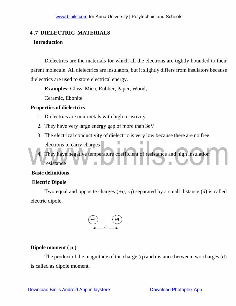
Two equal and opposite charges (+q, -q) separated by a small distance (d) is called
electric dipole.
Dipole moment ( μ )
The product of the magnitude of the charge (q) and distance between two charges (d)
is called as dipole moment.
www.binils.com for Anna University | Polytechnic and Schools
Download Binils Android App in laystore Download Photoplex App
Dipole moment μ = q. d
Its unit is Coulomb- meter
Permittivity (ε)
Permittivity represents the dielectric property of the medium. Permittivity of free space
is ε0 = 8.854 X10 -12 Farad/meter
Electric displacement vector (D)
The electric displacement vector (D) is a quantity which is a convenient function for
analyzing the electrostatic fields in the dielectrics. It is given by
Dielectric Constant(ε r)
It is the ratio between the permittivity of a medium (ε) and the permittivity of free
space (εo).
Polarization
The process of producing electric dipoles by the application of an external electric
field is called polarization in dielectrics.
Polarisability
We know that average dipole moment (μ) is proportional to the applied electrical field
(E)
www.binils.com for Anna University | Polytechnic and Schools
Download Binils Android App in laystore Download Photoplex App
Where α is the polarizability
Polarisability is defined as the ratio of the average dipole moment per unit electrical field
applied. Its unit is Farad-metre2
Polarization vector (p)
It is defined as the dipole moment per unit volume
Its unit is Coulomb – meter-2
Polar molecules
Molecules have permanent dipole moment even in the absence of an applied field is
called polar molecules.
Example: CHCl3, H2O,HCl
Non polar molecules
Molecules do not have permanent dipole moment is called non-polar molecules.
Example: CCl4, CO2, H2
Active dielectrics
When a dielectric is subjected to an external electric field, if the dielectric actively
accepts the electricity, then they are termed as active dielectrics. Thus active dielectrics are
the dielectrics which can easily adopt itself to store the electrical energy in it.
Example: Piezoelectric, ferroelectrics, pyro electrics
Passive dielectrics
www.binils.com for Anna University | Polytechnic and Schools
Download Binils Android App in laystore Download Photoplex App
These dielectrics are also called insulating materials. As the name itself suggests
conduction will not take place through these dielectrics. Thus passive dielectrics are the
dielectrics which restrict the flow of electrical energy in it.
Example: Glass, Mica, Plastic
www.binils.com for Anna University | Polytechnic and Schools
Download Binils Android App in Playstore Download Photoplex App
4.3. Domain Theory of Ferro Magnetism
This theory was proposed by Weiss in 1907. It explains the hysteresis and the properties of
ferromagnetic materials.
Postulates of domain theory:
1. A ferromagnetic material is divided into a large number of small region called domains
(0.1 to 1 of area)
2. In each domain the magnetic moments are in same direction.
3. But the magnetic moment varies from domain to domain and the net magnetization is
zero,
4. In the absence external magnetic field all the magnetic moments are in different
direction.
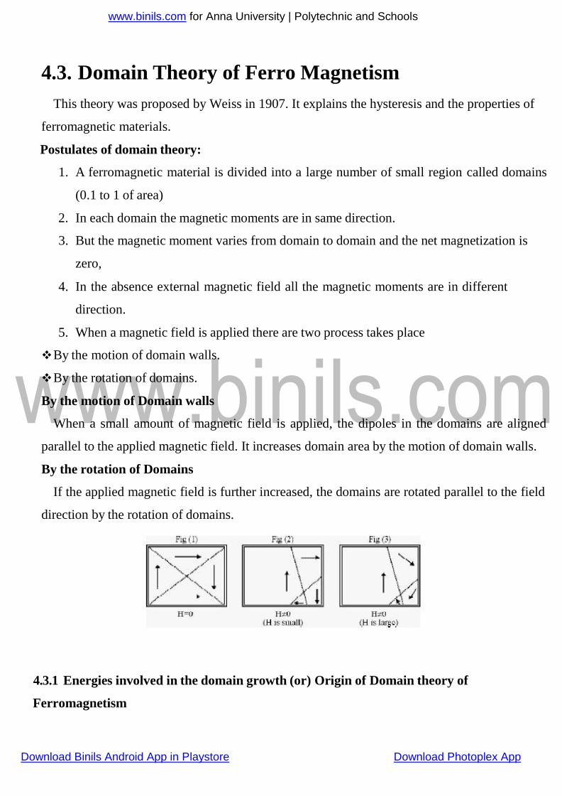
5. When a magnetic field is applied there are two process takes place
By the motion of domain walls.
By the rotation of domains.
By the motion of Domain walls
When a small amount of magnetic field is applied, the dipoles in the domains are aligned
parallel to the applied magnetic field. It increases domain area by the motion of domain walls.
By the rotation of Domains
If the applied magnetic field is further increased, the domains are rotated parallel to the field
direction by the rotation of domains.
4.3.1 Energies involved in the domain growth (or) Origin of Domain theory of
Ferromagnetism
www.binils.com for Anna University | Polytechnic and Schools
Download Binils Android App in Playstore Download Photoplex App
The total internal energy of the domain structure in a ferromagnetic material is made up from
the following
1. Exchange energy (or) Magnetic field energy.
2. Crystalline energy (or) Anisotropy energy.
3. Domain wall energy (or) Bloch wall energy.
4. Magnetostriction energy
1. Exchange energy (or) Magnetic Field energy
“The interaction energy which makes the adjacent dipoles align themselves” is the called
exchange energy (or) magnetic field energy. It arises from an interaction of electron spins. It
depends upon the inter atomic distance. This exchange energy also called magnetic field
energy. Whose energy is required in
assembling the atomic magnets into a single domain
and this work done is stored as potential energy. The
volume of the domain may very between 10–2 to 10–6
cm3.
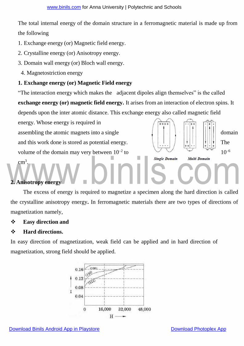
2. Anisotropy energy
The excess of energy is required to magnetize a specimen along the hard direction is called
the crystalline anisotropy energy. In ferromagnetic materials there are two types of directions of
magnetization namely,
Easy direction and
Hard directions.
In easy direction of magnetization, weak field can be applied and in hard direction of
magnetization, strong field should be applied.
www.binils.com for Anna University | Polytechnic and Schools
Crystalline anisotropy energy is energy of magnetization which is the function of crystal
orientation. As shown in figure magnetization curves for iron with the applied field along different
crystallographic direction crystallographic directions have been drawn. For example, in BCC iron
the easy direction is [100], the medium direction is [110], and the hard direction [111]. This energy
is very important in determining the characteristic domain boundaries.
3. Domain wall energy or Bloch wall energy
A thin boundary or region that separates adjacent domains in different directions is called domain
wall or Bloch wall. The size of the Bloch walls is about 200 to 300 lattice constant thickness. The
energy of domain wall is due to both exchange energy and anisotropic energy. Based on the spin
alignments, two types of Bloch walls may arise, namely
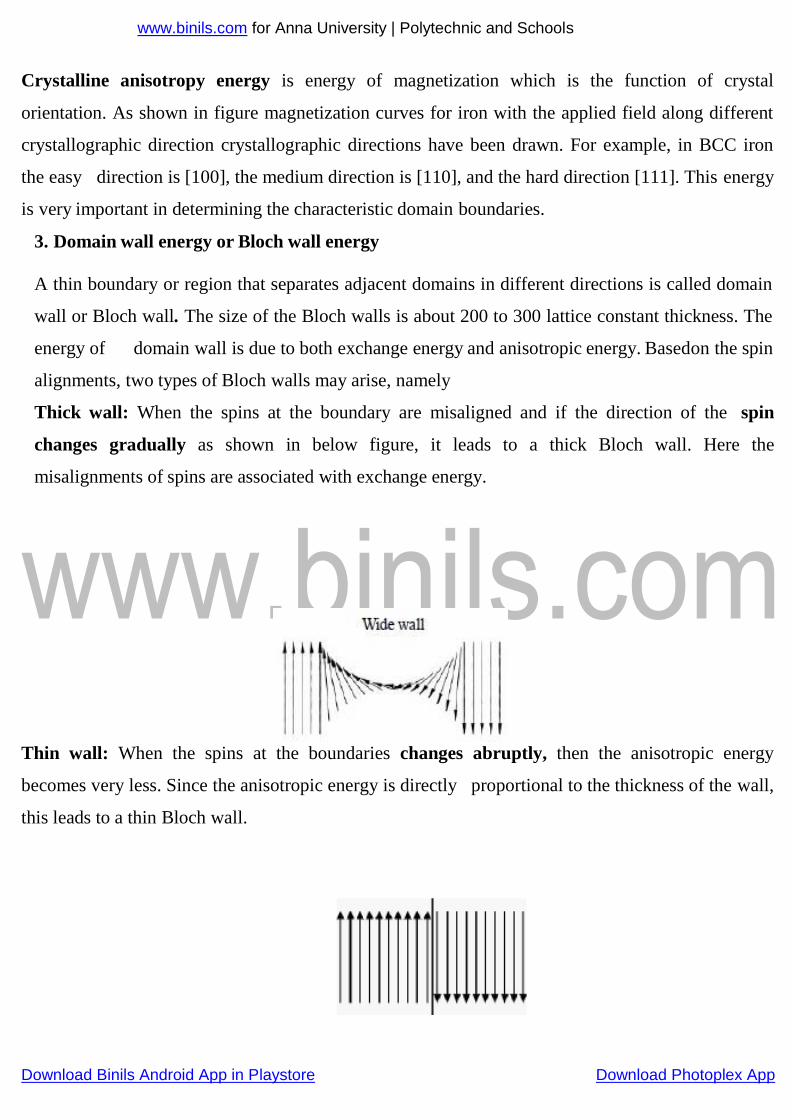
Thick wall: When the spins at the boundary are misaligned and if the direction of the spin
changes gradually as shown in below figure, it leads to a thick Bloch wall. Here the
misalignments of spins are associated with exchange energy.
Thin wall: When the spins at the boundaries changes abruptly, then the anisotropic energy
becomes very less. Since the anisotropic energy is directly proportional to the thickness of the wall,
this leads to a thin Bloch wall.
Download Binils Android App in Playstore Download Photoplex App
www.binils.com for Anna University | Polytechnic and Schools
Download binils Android App in playstore Download Photoplex
4. Magetostriction energy
When a material is magnetized, it is found that it suffers a change in dimensions. This
phenomenon is known as Magnetostriction. This deformation is different along different
crystal directions. So if the domains are magnetized in different directions, they will either
expand or shrink. This means that work must be done against the elastic restoring forces. The work
done by the magnetic field against these elastic restoring forces is called magneto-elastic energy or
Magnetostrictive energy.
Download Binils Android App in Playstore Download Photoplex App
www.binils.com for Anna University | Polytechnic and Schools
Download Binils Android App in Playstore Download Photoplex App
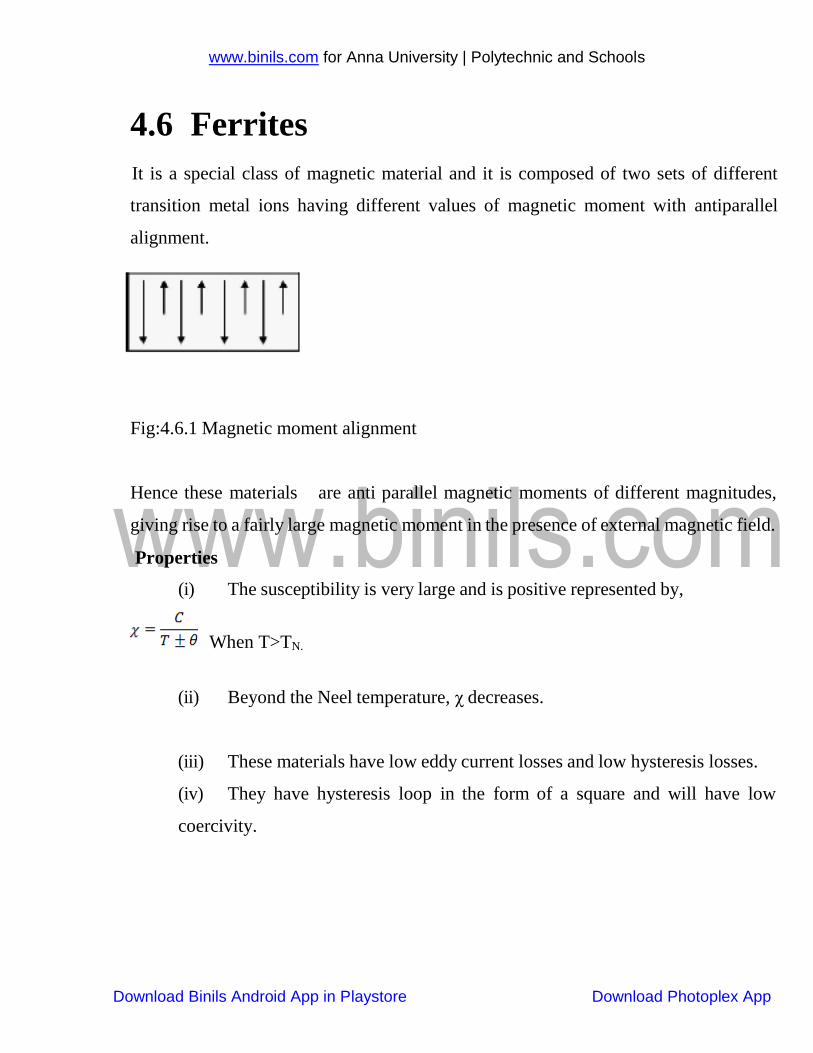
4.6 Ferrites
It is a special class of magnetic material and it is composed of two sets of different
transition metal ions having different values of magnetic moment with antiparallel
alignment.
Fig:4.6.1 Magnetic moment alignment
Hence these materials are anti parallel magnetic moments of different magnitudes,
giving rise to a fairly large magnetic moment in the presence of external magnetic field.
Properties
(i) The susceptibility is very large and is positive represented by,
When T>TN.
(ii) Beyond the Neel temperature, χ decreases.
(iii) These materials have low eddy current losses and low hysteresis losses.
(iv) They have hysteresis loop in the form of a square and will have low
coercivity.
www.binils.com for Anna University | Polytechnic and Schools
Download Binils Android App in Playstore Download Photoplex App
2 4
2 4
2 4
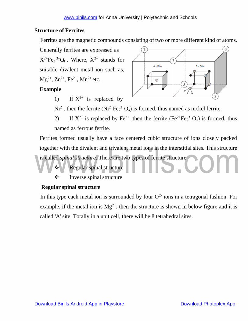
Structure of Ferrites
Ferrites are the magnetic compounds consisting of two or more different kind of atoms.
Generally ferrites are expressed as
X2+Fe 3+O . Where, X2+ stands for
suitable divalent metal ion such as,
Mg2+, Zn2+, Fe2+, Mn2+ etc.
Example
1) If X2+ is replaced by
Ni2+, then the ferrite (Ni2+Fe 3+O ) is formed, thus named as nickel ferrite.
2) If X2+ is replaced by Fe2+, then the ferrite (Fe2+Fe 3+O ) is formed, thus
named as ferrous ferrite.
Ferrites formed usually have a face centered cubic structure of ions closely packed
together with the divalent and trivalent metal ions in the interstitial sites. This structure
is called spinal structure. There are two types of ferrite structure.
Regular spinal structure
Inverse spinal structure
Regular spinal structure
In this type each metal ion is surrounded by four O2- ions in a tetragonal fashion. For
example, if the metal ion is Mg2+, then the structure is shown in below figure and it is
called 'A' site. Totally in a unit cell, there will be 8 tetrahedral sites.
www.binils.com for Anna University | Polytechnic and Schools
Download Binils Android App in Playstore Download Photoplex App
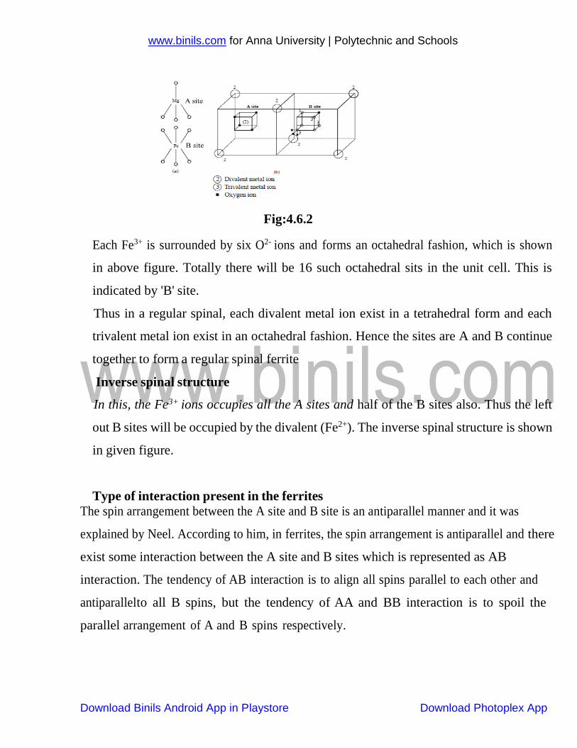
Fig:4.6.2
Each Fe3+ is surrounded by six O2- ions and forms an octahedral fashion, which is shown
in above figure. Totally there will be 16 such octahedral sits in the unit cell. This is
indicated by 'B' site.
Thus in a regular spinal, each divalent metal ion exist in a tetrahedral form and each
trivalent metal ion exist in an octahedral fashion. Hence the sites are A and B continue
together to form a regular spinal ferrite
Inverse spinal structure
In this, the Fe3+ ions occupies all the A sites and half of the B sites also. Thus the left
out B sites will be occupied by the divalent (Fe2+). The inverse spinal structure is shown
in given figure.
Type of interaction present in the ferrites
The spin arrangement between the A site and B site is an antiparallel manner and it was
explained by Neel. According to him, in ferrites, the spin arrangement is antiparallel and there
exist some interaction between the A site and B sites which is represented as AB
interaction. The tendency of AB interaction is to align all spins parallel to each other and
antiparallel to all B spins, but the tendency of AA and BB interaction is to spoil the
parallel arrangement of A and B spins respectively.
www.binils.com for Anna University | Polytechnic and Schools
Download Binils Android App in Playstore Download Photoplex App
Since AB is very strong as compared with AA and BB, the effect of AB interaction
dominates and gives rise to antiparallel spin alignment.
Applications of Ferrites
It is used to produce ultrasonic waves by magneto striction principle
It is used in audio and video transformers
It is used in radio receivers
It is used to amplifier input signals with low noise
It is used to as a power limiters
It is used in computer and data processing circuit
It is used as Gyrators, circulator and Isolator
www.binils.com for Anna University | Polytechnic and Schools
Download Binils Android App in Playstore Download Photoplex App
4.7.4 Ferro electricity and its applications
When a dielectric material exhibits electric polarization even in the absence of
external field, it is known as ferroelectricity and these materials are termed as
ferroelectrics.Ferroelectrics are anisotropic crystals which exhibit spontaneous
polarization.
Examples:
Rochelle salt
Potassium phosphate
Barium titanate
Potassium niobate
Lithium niobate
Lithium tantalate etc.
Properties:
1. The dielectric constant of these ferroelectric materials is above 2000.
2. It will not vary with respect to temperature.
3. The dielectric constant reaches maximum value only at a particular temperature
called Curie temperature.
4. The polarization does not varies linearly with respect to electric field.
5. Ferro electrics exhibits electric polarization very easily, even in the absence of
external electric field
6. They exhibit domain structure similar to that of ferromagnetic material.
7. Ferro electric materials also exhibitshysteresis.
8. Ferro electric materials exhibit piezo electricity and pyro electricity.
Piezo electricity means the creation of electric polarization by mechanical
stress.
www.binils.com for Anna University | Polytechnic and Schools
Download Binils Android App in Playstore Download Photoplex App
Pyro electricity means the creation of electric polarization by thermal stress.
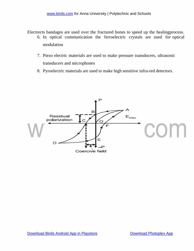
Hysteresis of Ferroelectric Materials
The ferroelectrics are known as non-linear dielectrics. Such materials exhibit
hysteresis curve similar to that of ferromagnetic materials. The lagging of polarization
‘P’ behind the applied electric field E is called dielectric hysteresis.
When a ferroelectric material is subjected to external electric field (E) the
polarization (P) increases with respect to the field applied and it reaches the maximum
value ‘OA’. If now the applied electric field is reduced, the polarization also decreases
from a, and when E becomes zero a small amount of polarization exists in the material
is called spontaneous (or) residual polarization.
In order to reduce the value of polarization to zero, a reversing electric field ‘OC’
should be applied. This field is known as coercive field. Thus the variation of ‘P’ with
respect to ‘E’ traced along the closed path ‘ABCDEFA’ in one full cycle of polarization
and depolarization is called hysteresis or the hysteresis curve.
Applications
1. Ferro electric materials are used to produce ultrasonic
2. Ferro electrics are also used in SONAR, Strain gauges etc.
3. Ferroelectrics are used to measure and control the temperature.
4. They are also used as frequency stabilizers and crystal controlled oscillators.
5. Electrects are the type of ferroelectric material used in the production of
capacitor, microphones, gas filters etc
www.binils.com for Anna University | Polytechnic and Schools
Download Binils Android App in Playstore Download Photoplex App
Electrects bandages are used over the fractured bones to speed up the healing process. 6. In optical communication the ferroelectric crystals are used for optical
modulation
7. Piezo electric materials are used to make pressure transducers, ultrasonic
transducers and microphones
8. Pyroelectric materials are used to make high sensitive infra-red detectors.
Fig:4.7.4.(i)
www.binils.com for Anna University | Polytechnic and Schools
Download Binils Android App in Playstore Download Photoplex App
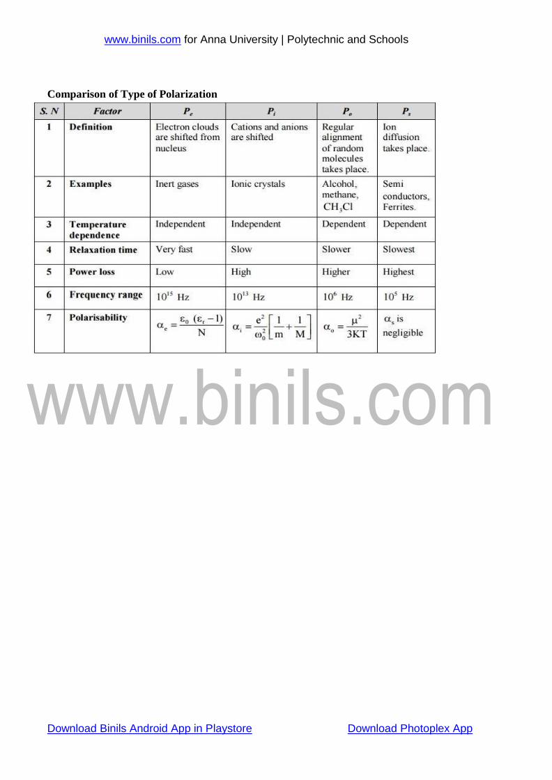
Comparison of Type of Polarization
www.binils.com for Anna University | Polytechnic and Schools
Download Binils Android App in Playstore Download Photoplex App
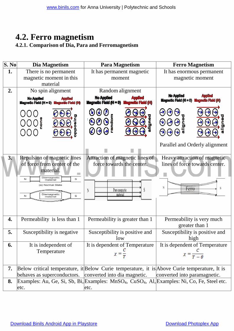
4.2. Ferro magnetism 4.2.1. Comparison of Dia, Para and Ferromagnetism
S. No Dia Magnetism Para Magnetism Ferro Magnetism
1. There is no permanent
magnetic moment in this material
It has permanent magnetic
moment
It has enormous permanent
magnetic moment
2. No spin alignment Random alignment
Parallel and Orderly alignment
3. Repulsion of magnetic lines
of force from center of the
material.
Attraction of magnetic lines of
force towards the center.
Heavy attraction of magnetic
lines of force towards center.
4. Permeability is less than 1 Permeability is greater than 1 Permeability is very much greater than 1
5. Susceptibility is negative Susceptibility is positive and low
Susceptibility is positive and high
6. It is independent of
Temperature
It is dependent of Temperature
It is dependent of Temperature
7. Below critical temperature, it
behaves as superconductors.
Below Curie temperature, it is
converted into dia magnetic.
Above Curie temperature, It is
converted into paramagnetic.
8. Examples: Au, Ge, Si, Sb, Bi, etc.
Examples: MnSO4, CuSO4, Al, etc.
Examples: Ni, Co, Fe, Steel etc.
www.binils.com for Anna University | Polytechnic and Schools
Download Binils Android App in Playstore Download Photoplex App
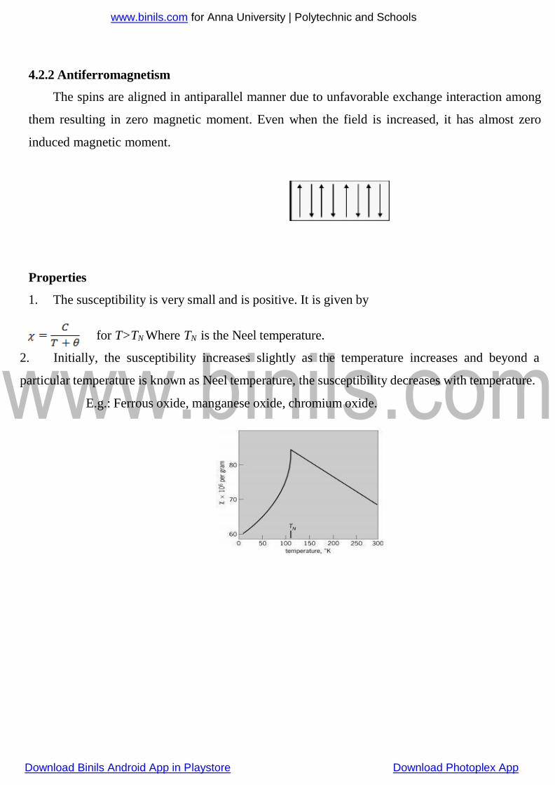
4.2.2 Antiferromagnetism
The spins are aligned in antiparallel manner due to unfavorable exchange interaction among
them resulting in zero magnetic moment. Even when the field is increased, it has almost zero
induced magnetic moment.
Properties
1. The susceptibility is very small and is positive. It is given by
for T>TN Where TN is the Neel temperature.
2. Initially, the susceptibility increases slightly as the temperature increases and beyond a
particular temperature is known as Neel temperature, the susceptibility decreases with temperature.
E.g.: Ferrous oxide, manganese oxide, chromium oxide.
www.binils.com for Anna University | Polytechnic and Schools
Download Binils Android App in Playstore Download Photoplex App
4.7.2 Frequency and temperature dependence of polarization
On the application of an alternating electric field, the polarization process occurs
as a function of time. The polarization P(t) as a function of time ‘t’ is given by
𝑃(𝑡) = 𝑃 [1 − 𝑒 (−𝑡
)
𝑡𝑟 ]
Where,‘P’ is the maximum polarization attained on external applied static field
and ‘tr’ is the relaxation time for the particular polarization process. The relaxation time
is a measure of the time scale of a polarization process. This varies for different
polarization process.
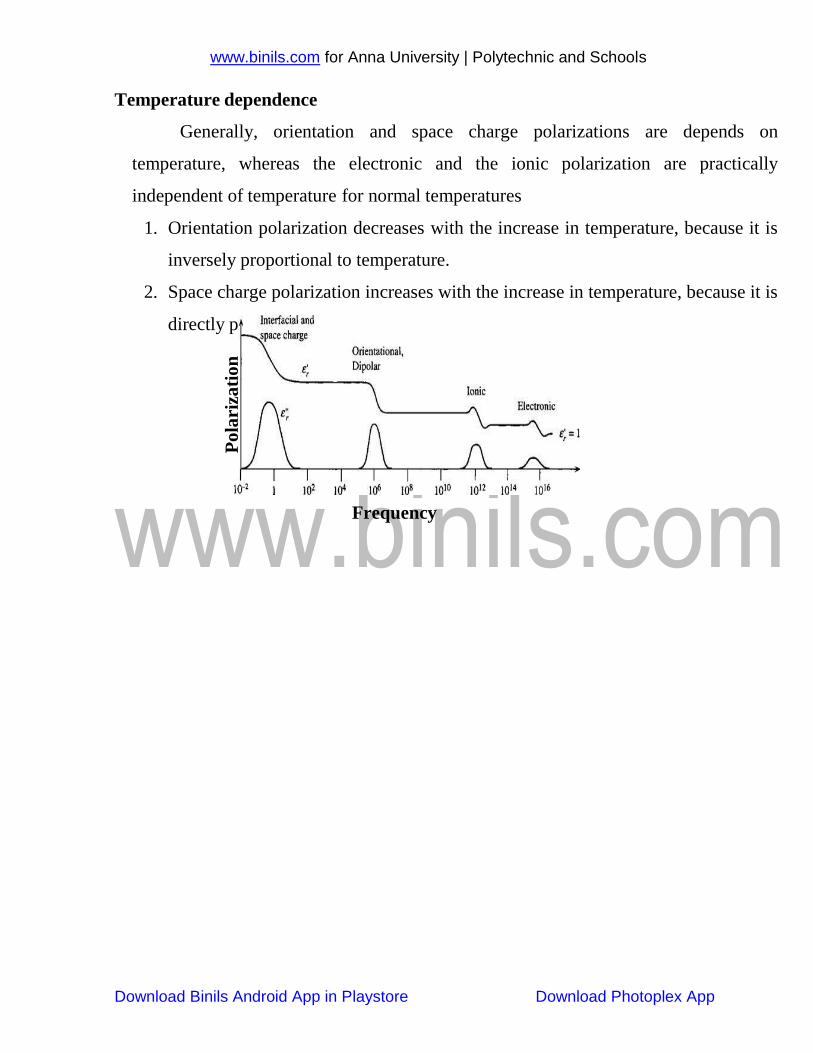
Frequency dependent polarization
1. Electronic polarization is very fast. The frequency of the voltage is very high, which
is in the optical range (≈1015 Hz). Thus it occurs at all frequencies.
2. Ionic polarization is slower than the electronic polarization, because the mass of the
ions are heavier than the electrons cloud. It is occurs in the infra-red frequency
region (1013 Hz).
3. Orientation polarization is slower than the ionic polarization and which is occurs
only at electrical frequency (106 Hz).
4. Space charge polarization is the slowest process and occurs only at power
frequencies (102 Hz).
5. Thus at lower frequencies, the value of the total polarization is very high and at
higher frequencies (optical frequencies) the value of the total polarization is very
small.
www.binils.com for Anna University | Polytechnic and Schools
Download Binils Android App in Playstore Download Photoplex App
roportional to temperature
Temperature dependence
Generally, orientation and space charge polarizations are depends on
temperature, whereas the electronic and the ionic polarization are practically
independent of temperature for normal temperatures
1. Orientation polarization decreases with the increase in temperature, because it is
inversely proportional to temperature.
2. Space charge polarization increases with the increase in temperature, because it is
directly p
Frequency
Po
lari
zati
on
www.binils.com for Anna University | Polytechnic and Schools
Download Binils Android App in Playstore Download Photoplex App
Hmax
-Hmax
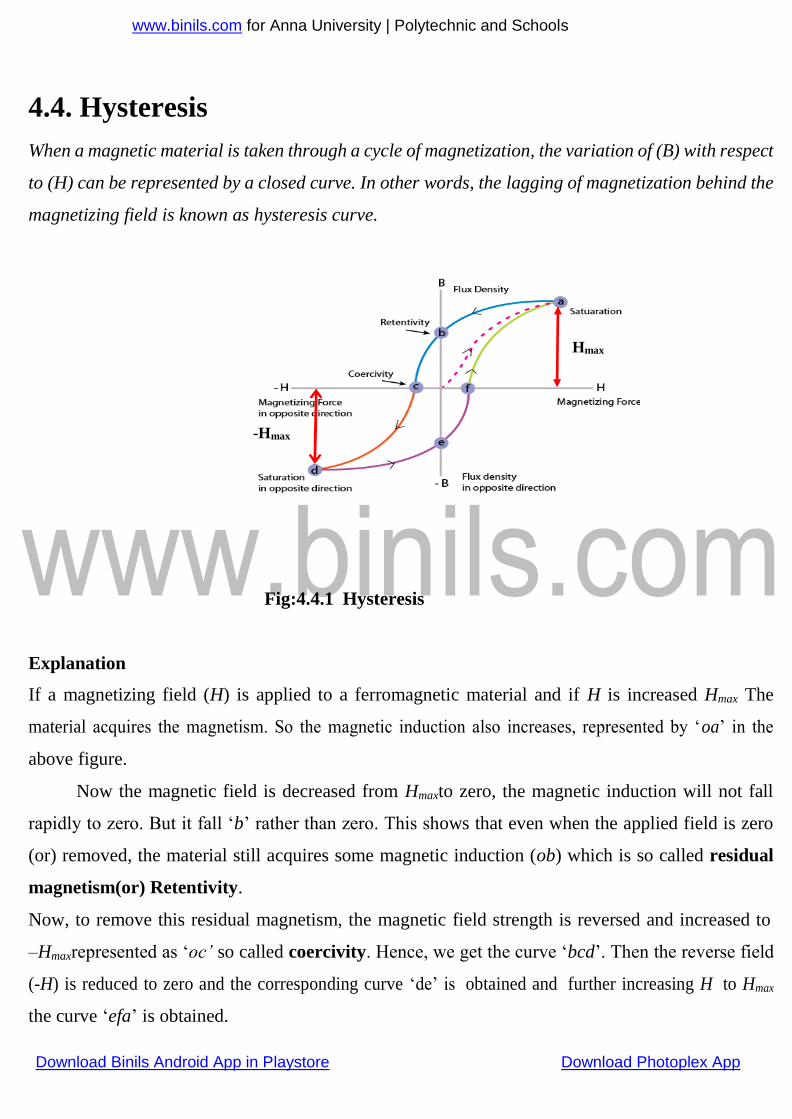
4.4. Hysteresis
When a magnetic material is taken through a cycle of magnetization, the variation of (B) with respect
to (H) can be represented by a closed curve. In other words, the lagging of magnetization behind the
magnetizing field is known as hysteresis curve.
Fig:4.4.1 Hysteresis
Explanation
If a magnetizing field (H) is applied to a ferromagnetic material and if H is increased Hmax The
material acquires the magnetism. So the magnetic induction also increases, represented by ‘oa’ in the
above figure.
Now the magnetic field is decreased from Hmaxto zero, the magnetic induction will not fall
rapidly to zero. But it fall ‘b’ rather than zero. This shows that even when the applied field is zero
(or) removed, the material still acquires some magnetic induction (ob) which is so called residual
magnetism(or) Retentivity.
Now, to remove this residual magnetism, the magnetic field strength is reversed and increased to
–Hmaxrepresented as ‘oc’ so called coercivity. Hence, we get the curve ‘bcd’. Then the reverse field
(-H) is reduced to zero and the corresponding curve ‘de’ is obtained and further increasing H to Hmax
the curve ‘efa’ is obtained.
www.binils.com for Anna University | Polytechnic and Schools
Download Binils Android App in Playstore Download Photoplex App
C
B
A
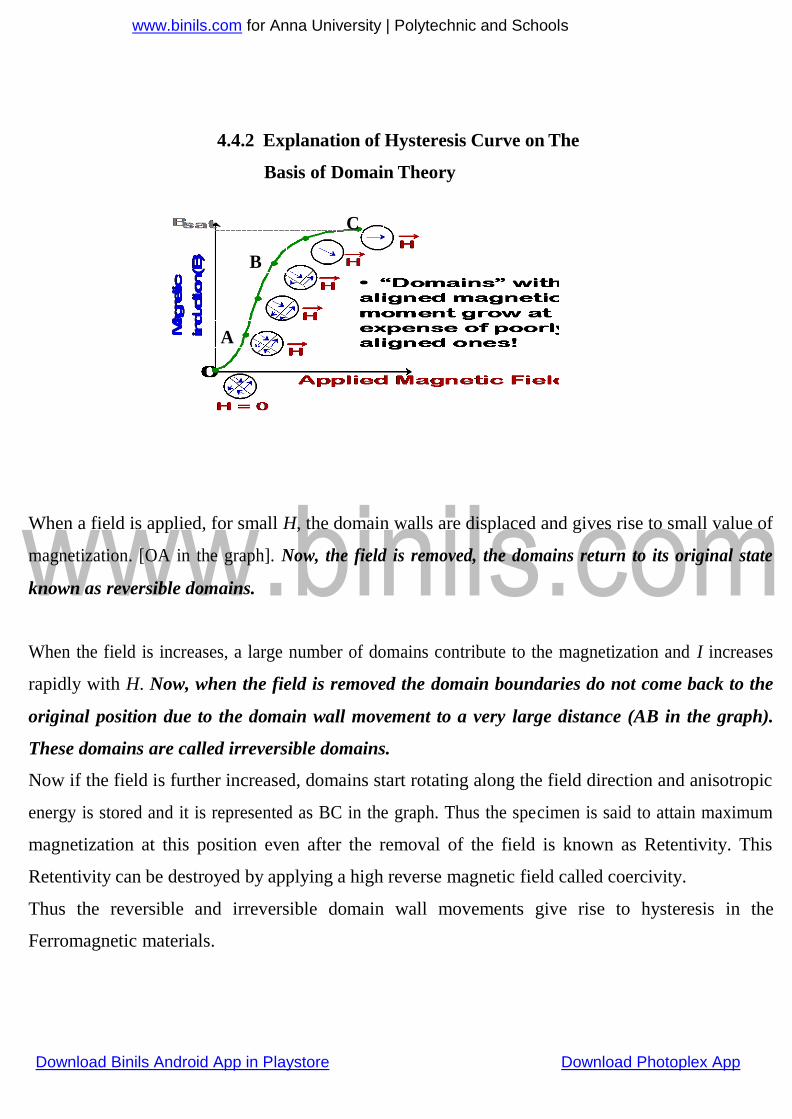
4.4.2 Explanation of Hysteresis Curve on The
Basis of Domain Theory
When a field is applied, for small H, the domain walls are displaced and gives rise to small value of
magnetization. [OA in the graph]. Now, the field is removed, the domains return to its original state
known as reversible domains.
When the field is increases, a large number of domains contribute to the magnetization and I increases
rapidly with H. Now, when the field is removed the domain boundaries do not come back to the
original position due to the domain wall movement to a very large distance (AB in the graph).
These domains are called irreversible domains.
Now if the field is further increased, domains start rotating along the field direction and anisotropic
energy is stored and it is represented as BC in the graph. Thus the specimen is said to attain maximum
magnetization at this position even after the removal of the field is known as Retentivity. This
Retentivity can be destroyed by applying a high reverse magnetic field called coercivity.
Thus the reversible and irreversible domain wall movements give rise to hysteresis in the
Ferromagnetic materials.
www.binils.com for Anna University | Polytechnic and Schools
Download Binils Android App in Playstore Download Photoplex App
UNIT-IV
MAGNETIC PROPERTIES OF MATERIALS
Introduction
Magnetic materials widely used in nuclear magnetic resonance equipment’s and
particle accelerators etc. These devices play vital role in our modern living. The knowledge
about the origin and the behavior of magnetic materials will be of great help in proper
utilization of such devices.
Basic definitions
Magnetic field
Space around the magnet is called magnetic field.
Magnetic dipole
Magnetic dipole is a system consisting of two equal and opposite magnetic pole
separated by a small distance (l).
Magnetic dipole moment
The diploe moment of a magnet is defined as the product of its pole strength (m) and
the distance between two poles (l). Unit -Weber/m.
Magnetic moment = m x l
Magnetic flux (Φ)
The number of magnetic lines of force passing through a surface is known as magnetic
flux. It is represented by the symbol Φ. Unit -Webber
Magnetic flux density (or) magnetic Induction (B)
Magnetic flux density is defined as the number of magnetic lines of force passing through
a unit area of cross-section.
B = Φ/A (Weber/m2)
Intensity of magnetization (I)
It is the measure of magnetization of a magnetized specimen. It can also be defined as
the magnetic moment per unit volume.
www.binils.com for Anna University | Polytechnic and Schools
Download Binils Android App in Playstore Download Photoplex App
I = M/V (A/m)
Magnetic field intensity (H)
It is defined as the force experienced by a unit north pole placed in a magnetic field
H = F/m (A/m)
Magnetic permeability (μ)
It is defined as the ratio of the magnetic flux density to the applied magnetic field
intensity
μ = B/H (Henry/m)
Relative permeability (μr)
It is the ratio between the absolute permeability of a medium to the permeability of a
free space.
μr = μ /μo (No unit)
Magnetic susceptibility (χ)
It is the ratio of intensity of magnetization induced in it to the magnetizing field
χ = I/H
Relation between χ and μ
We know that the magnetic induction is,
B = μ H
This equation can be written in another way as
B= μo (I+H)
= μoH ((I/H) +1)
B = μoH (χ +1)
B/H = μo (χ +1)
μ=μo(χ +1)
of electrons in an atom. The permanent magnetic moment arises due to the
Orbital angular momentum of the electron
Spin angular momentum of the electron
Nuclear magnetic moment
Orbital angular momentum of the electron
The orbital motion of electron revolving about a nucleus is equivalent to a tiny
www.binils.com for Anna University | Polytechnic and Schools
Download Binils Android App in Playstore Download Photoplex App
current loop. This produces a magnetic moment perpendicular to the plane of the
orbit.
Let us consider an electron moving with constant speed “v” in a circular radius “r”.
Let “T” be time taken for one revolution and “e” be the charge of the electron.
Magnetic moment associated with the orbit is,
The current I across at any point in the orbit is,
Substitute equation (2) and (3) in equation (1), we get
Since, T is time taken by electron for one complete revolution. The distance
(Circumference of the orbit) travelled by an electron in a given time (T) is called
velocity.
Substitute T in equation (4), we get,
Dividing and multiplying the RHS of equation (5) by m (mass of the electron), we get
www.binils.com for Anna University | Polytechnic and Schools
Download Binils Android App in Playstore Download Photoplex App
Where, L = mvr is the orbital angular momentum of the electron. The equation (6) is the
final expression for the magnetic moment associated with the orbital motion of the
electron.
Bohr Magnetron
The magnetic moment associated with the orbital magnetic moment of the electron is
According to the quantum theory, orbital angular momentum is,
Where, n is the orbital angular momentum quantum number and substitute equation (2) in
equation (1) we the Bohr magnetron,
This is the final expression for Bohr magnetron and the value is calculated by the
substitution of all the constants in equation (3). The calculated Bohr magnetron value is
.
Spin angular momentum of the electron
Similar to orbital motion, magnetic moment due to spin motion of the electron is given
by,
Where, S is the spin angular momentum and it is given by,
Where, s is the spin quantum number and it takes +1/2 or -1/2.
www.binils.com for Anna University | Polytechnic and Schools
Download Binils Android App in Playstore Download Photoplex App
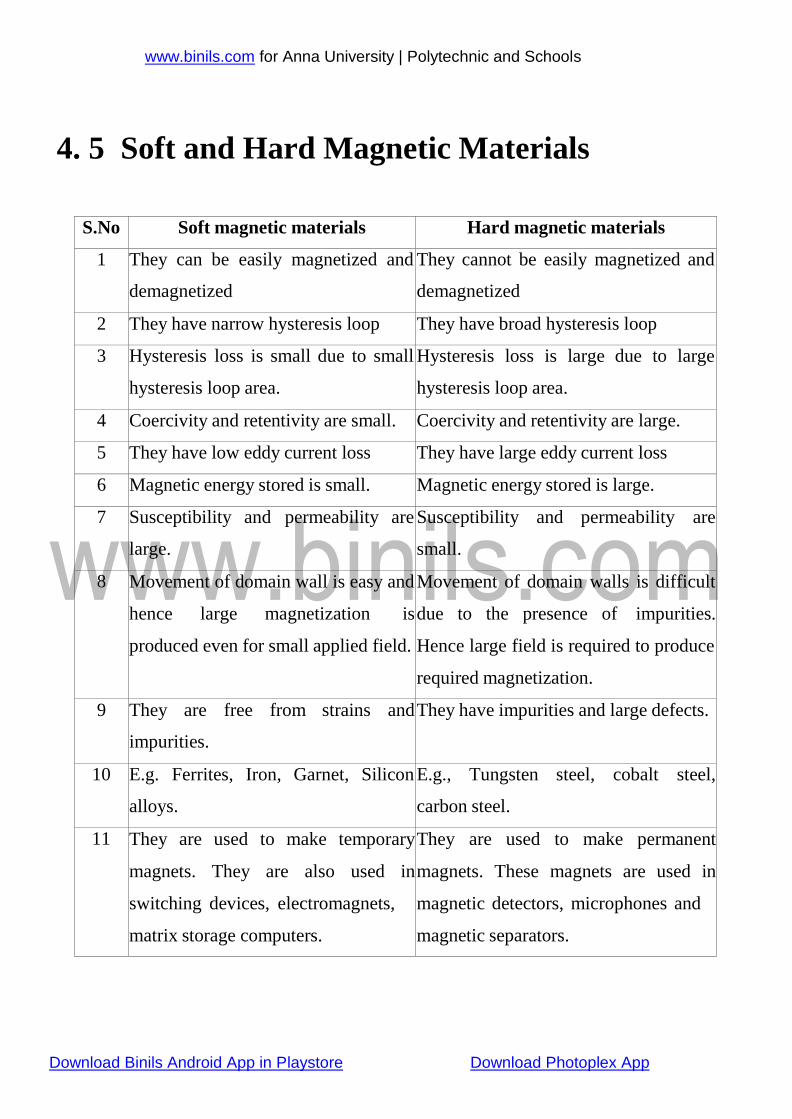
4. 5 Soft and Hard Magnetic Materials
S.No Soft magnetic materials Hard magnetic materials
1 They can be easily magnetized and
demagnetized
They cannot be easily magnetized and
demagnetized
2 They have narrow hysteresis loop They have broad hysteresis loop
3 Hysteresis loss is small due to small
hysteresis loop area.
Hysteresis loss is large due to large
hysteresis loop area.
4 Coercivity and retentivity are small. Coercivity and retentivity are large.
5 They have low eddy current loss They have large eddy current loss
6 Magnetic energy stored is small. Magnetic energy stored is large.
7 Susceptibility and permeability are
large.
Susceptibility and permeability are
small.
8 Movement of domain wall is easy and
hence large magnetization is
produced even for small applied field.
Movement of domain walls is difficult
due to the presence of impurities.
Hence large field is required to produce
required magnetization.
9 They are free from strains and
impurities.
They have impurities and large defects.
10 E.g. Ferrites, Iron, Garnet, Silicon
alloys.
E.g., Tungsten steel, cobalt steel,
carbon steel.
11 They are used to make temporary
magnets. They are also used in
switching devices, electromagnets,
matrix storage computers.
They are used to make permanent
magnets. These magnets are used in
magnetic detectors, microphones and
magnetic separators.
www.binils.com for Anna University | Polytechnic and Schools
Download Binils Android App in Playstore Download Photoplex App
4 .8 Super Conductors and their properties
Super conductors
Super conductors are the materials which has zero resistivity and
behaves as dia magnet below its transition temperature.
Transition temperature: The temperature at which the normal conductors
changed into superconductor is called transition temperature.
Properties:
1. Electrical resistance: It has zero electrical resistance.
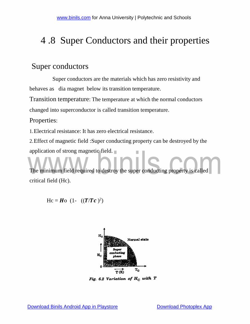
2. Effect of magnetic field :Super conducting property can be destroyed by the
application of strong magnetic field.
The minimum field required to destroy the super conducting property is called
critical field (Hc).
Hc = 𝑯o (1- ((𝑻/𝑻𝒄 )2)
www.binils.com for Anna University | Polytechnic and Schools
Download Binils Android App in Playstore Download Photoplex App
Effect of heavy current:
Super conducting property can be destroyed by the application of strong electric
field.
Critical current required to destroy the superconducting property is Ic = 2rc
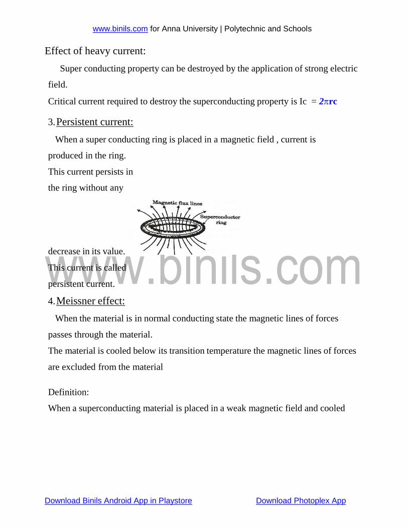
3. Persistent current:
When a super conducting ring is placed in a magnetic field , current is
produced in the ring.
This current persists in
the ring without any
decrease in its value.
This current is called
persistent current.
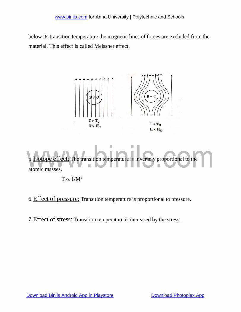
4. Meissner effect:
When the material is in normal conducting state the magnetic lines of forces
passes through the material.
The material is cooled below its transition temperature the magnetic lines of forces
are excluded from the material
Definition:
When a superconducting material is placed in a weak magnetic field and cooled
www.binils.com for Anna University | Polytechnic and Schools
Download Binils Android App in Playstore Download Photoplex App
below its transition temperature the magnetic lines of forces are excluded from the
material. This effect is called Meissner effect.
5. Isotope effect: The transition temperature is inversely proportional to the
atomic masses.
Tc 1/Mα
6. Effect of pressure: Transition temperature is proportional to pressure.
7. Effect of stress: Transition temperature is increased by the stress.
www.binils.com for Anna University | Polytechnic and Schools
Download Binils Android App in Playstore Download Photoplex App
4 3
4.7.1 Polarization mechanisms in dielectrics
Langevin-Debye Equation
.The application of an electric field to a dielectric material creates the dipoles
resulting in polarization. There are four different types of polarization namely
(i) Electronic (or) Induced polarization
(ii) Ionic (or) atomic polarization
(iii) Orientation polarization
(iv) Space-charge (or) Interfacial polarization
4.7.1(i).Electronic (or) Induced polarization
Electronic polarization occurs due to the displacement of positively charged nucleus
and negatively charged electrons in opposite directions, when an external electric field is
applied.
Induced dipole moment is
(1)
Where αe is known as electronic polarizability. Monoatomic gases exhibit this kind
of polarization. It is proportional to the volume of the atoms and independent of temperature.
Calculation of electronic polarizability (α e)
a) Without field
Let us consider a classical model of an atom. Assume the charge of nucleus of that
atom is (+Ze).The nucleus surrounded by an electron cloud of charge(-Ze), which is
distributed throughout the sphere (atom) of radius R.
The charge density ‘ρ’ of the electrons
ρ= 𝑇𝑜𝑡𝑎𝑙 𝑛𝑒𝑔𝑎𝑡𝑖𝑣𝑒 𝑐ℎ𝑎𝑟𝑔𝑒
𝑉𝑜𝑙𝑢𝑚𝑒 𝑜𝑓 𝑡ℎ𝑒 𝑎𝑡𝑜𝑚
The charge density ‘ρ’ of the electrons = −𝑍𝑒 𝜋𝑅
3
Charge density = −3 𝑍𝑒 ......................
(2) 4 𝜋𝑅3
b) With field
www.binils.com for Anna University | Polytechnic and Schools
Download Binils Android App in Playstore Download Photoplex App
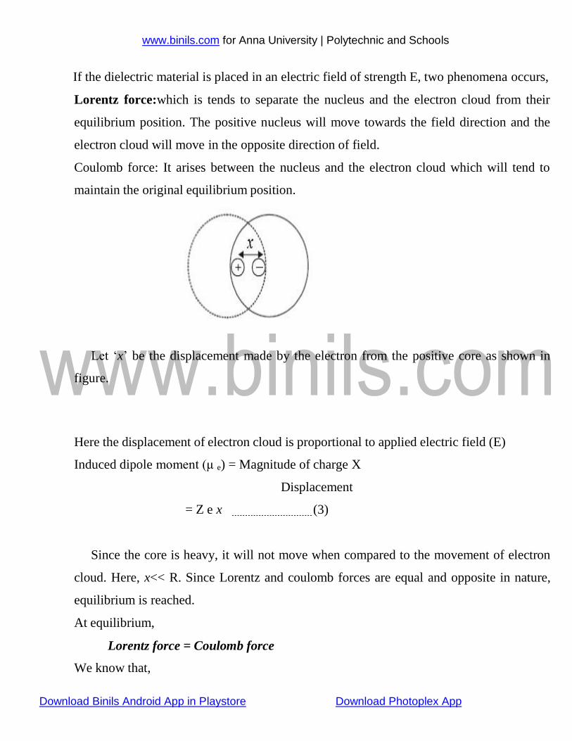
If the dielectric material is placed in an electric field of strength E, two phenomena occurs,
Lorentz force:which is tends to separate the nucleus and the electron cloud from their
equilibrium position. The positive nucleus will move towards the field direction and the
electron cloud will move in the opposite direction of field.
Coulomb force: It arises between the nucleus and the electron cloud which will tend to
maintain the original equilibrium position.
Let ‘x’ be the displacement made by the electron from the positive core as shown in
figure.
Here the displacement of electron cloud is proportional to applied electric field (E)
Induced dipole moment (μ e) = Magnitude of charge X
Displacement
= Z e x (3)
Since the core is heavy, it will not move when compared to the movement of electron
cloud. Here, x<< R. Since Lorentz and coulomb forces are equal and opposite in nature,
equilibrium is reached.
At equilibrium,
Lorentz force = Coulomb force
We know that,
www.binils.com for Anna University | Polytechnic and Schools
Download Binils Android App in Playstore Download Photoplex App
Lorentz force (FL) = Charge x Electric field
= - ZeE ………(4)
Coulomb force (FC) = 𝑄𝑍𝑒 4𝜋∈0𝑥2
(5)
Total number of negative charges (Q) enclosed in the sphere of radius x = charge density
charges of electrons x Volume of the sphere
−3 𝑍𝑒 4 𝑄 = 3
4𝜋𝑅3 ×
3 𝜋𝑥
Q = −𝑍𝑒𝑥3 ..............................
(6) 𝑅3
Substitute eqn. (6) in (5) we get,
Coulomb force (Fc) = 𝑍𝑒 4𝜋∈0𝑥2
×
−𝑍𝑒𝑥3
𝑅3
F = −𝑍2𝑒2𝑥
……… (7)
At equilibrium position,
Equation (4)= equation (7)
Therefore by substitution we get
c 4𝜋∈0𝑅3
-ZeE =−𝑍
2𝑒2𝑥
4𝜋∈0𝑅3
E = −𝑍𝑒𝑥
4𝜋∈0𝑅3
x = 4𝜋∈0𝑅3𝐸 ..........................
(8)
𝑍𝑒
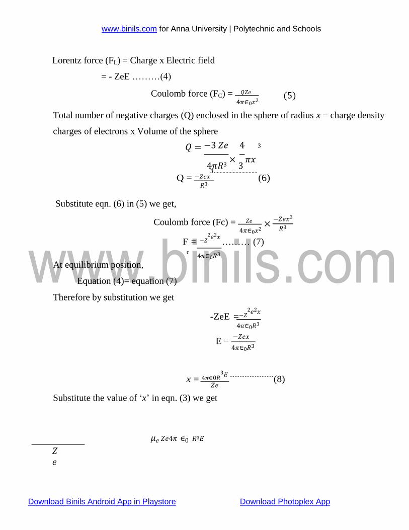
Substitute the value of ‘x’ in eqn. (3) we get
𝜇𝑒 𝑍𝑒4𝜋 ∈0 𝑅3𝐸
𝑍𝑒
www.binils.com for Anna University | Polytechnic and Schools
Download Binils Android App in Playstore Download Photoplex App
𝜇𝑒 = 4𝜋 ∈0 𝑅3𝐸 − − − − − (9)
Compare eqn. (9) and (1) we get,
4𝜋 ∈0 𝑅3𝐸 = 𝛼𝑒E
𝛼𝑒 = 4𝜋 ∈0 𝑅3 -------------- (10)
Where αeis called electronic polarization
Conclusion:
Electronic polarization is independent of temperature.
It is proportional to the volume of atoms in the material
Electronic polarization takes place in all dielectrics
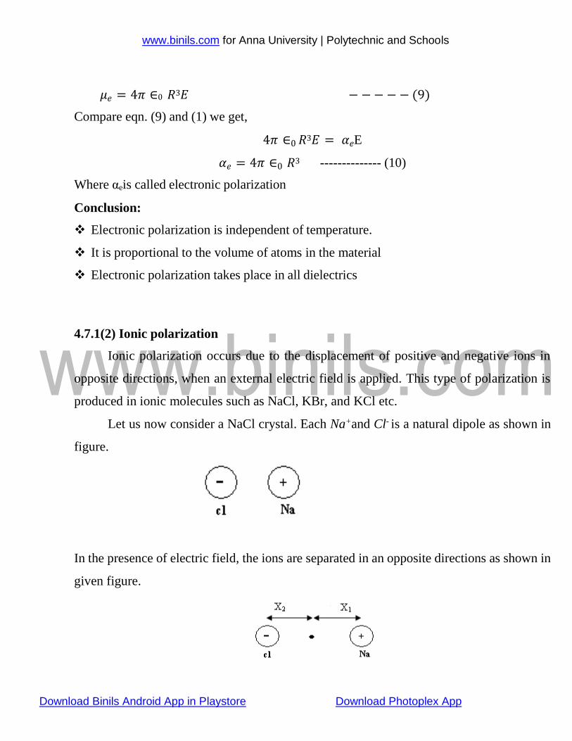
4.7.1(2) Ionic polarization
Ionic polarization occurs due to the displacement of positive and negative ions in
opposite directions, when an external electric field is applied. This type of polarization is
produced in ionic molecules such as NaCl, KBr, and KCl etc.
Let us now consider a NaCl crystal. Each Na+and Cl- is a natural dipole as shown in
figure.
In the presence of electric field, the ions are separated in an opposite directions as shown in
given figure.
www.binils.com for Anna University | Polytechnic and Schools
Download Binils Android App in Playstore Download Photoplex App
0
0
0
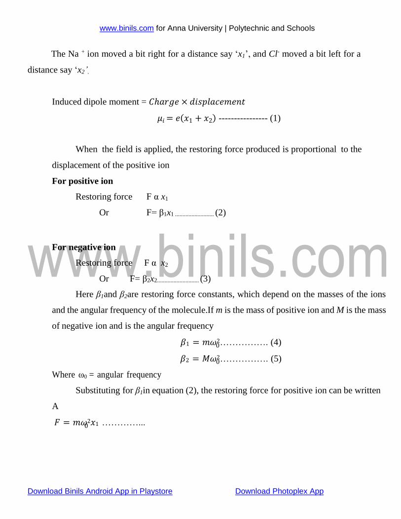
The Na + ion moved a bit right for a distance say ‘x1’, and Cl- moved a bit left for a
distance say ‘x2’.
Induced dipole moment = 𝐶ℎ𝑎𝑟𝑔𝑒 × 𝑑𝑖𝑠𝑝𝑙𝑎𝑐𝑒𝑚𝑒𝑛𝑡
𝜇𝑖 = 𝑒(𝑥1 + 𝑥2) ---------------- (1)
When the field is applied, the restoring force produced is proportional to the
displacement of the positive ion
For positive ion
Restoring force F α x1
Or F= β1x1 .......................... (2)
For negative ion
Restoring force F α x2
Or F= β2x2............................ (3)
Here β1and β2are restoring force constants, which depend on the masses of the ions
and the angular frequency of the molecule.If m is the mass of positive ion and M is the mass
of negative ion and is the angular frequency
𝛽1 = 𝑚𝜔2……………. (4)
𝛽2 = 𝑀𝜔2……………. (5)
Where ω0 = angular frequency
Substituting for β1in equation (2), the restoring force for positive ion can be written
A
𝐹 = 𝑚𝜔2𝑥1 …………...

www.binils.com for Anna University | Polytechnic and Schools
Download Binils Android App in Playstore Download Photoplex App
0
0
0
0
0
0
0
We know that
𝐹 = 𝑒𝐸……….(7)
Equating eqn.(6) and (7) we get
Therefore,
𝑒𝐸 = 𝑚𝜔2𝑥1
𝑥1 = 𝑒𝐸
…………….... (8) 𝑚𝜔2
Similarly for the negative ion we can write
𝑥2
Adding eqn.(9) and (10) we get
= 𝑒𝐸
𝑀𝜔2 …………….... (9)
𝑥1 + 𝑥2 = 𝑒𝐸
( 1
+
𝜔2 𝑚
1 )………… (10) 𝑀
Substitute equation(11) in eqn. (1) we get
But, from definition,
𝜇𝑖 = 𝑒2𝐸
( 1
+
𝜔2 𝑚
1 ) ------(11) 𝑀
𝜇𝑖 = 𝛼𝑖𝐸 ----------- (12)
Compare equation (12) and (13) we get,
𝛼𝑖𝐸 =
𝑒2𝐸 1 1
𝜔2 (𝑚 + 𝑀
)
Conclusion
𝛼𝑖 = 𝑒2
( 1
𝜔2 𝑚 +
1 )------- (13)
𝑀
So the ionic polarizability is inversely proportional to the square of the natural
frequency of the ionic molecule
It is directly proportional to reduced mass
It is independent of temperature
4.7.1(3) Orientation polarization
www.binils.com for Anna University | Polytechnic and Schools
Download Binils Android App in Playstore Download Photoplex App
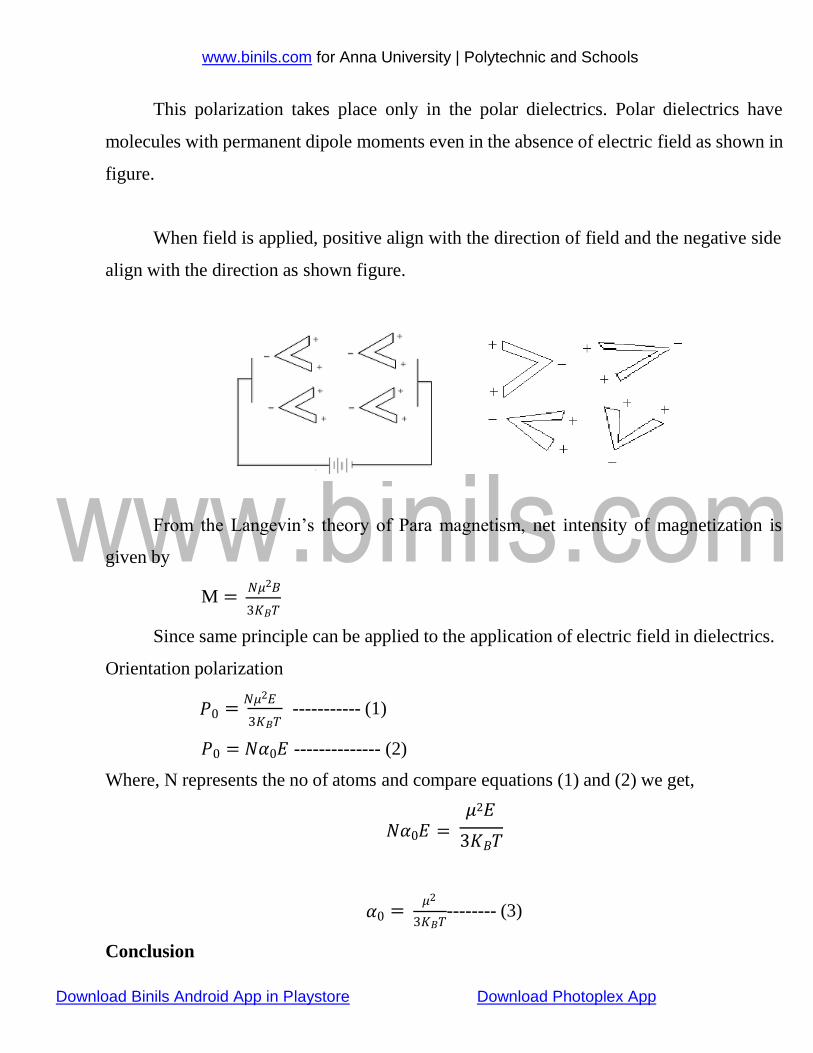
This polarization takes place only in the polar dielectrics. Polar dielectrics have
molecules with permanent dipole moments even in the absence of electric field as shown in
figure.
When field is applied, positive align with the direction of field and the negative side
align with the direction as shown figure.
From the Langevin’s theory of Para magnetism, net intensity of magnetization is
given by
M = 𝑁𝜇2𝐵
3𝐾𝐵𝑇
Since same principle can be applied to the application of electric field in dielectrics.
Orientation polarization
𝑃0 = 𝑁𝜇2𝐸
3𝐾𝐵𝑇
----------- (1)
𝑃0 = 𝑁𝛼0𝐸 -------------- (2)
Where, N represents the no of atoms and compare equations (1) and (2) we get,
𝜇2𝐸 𝑁𝛼0𝐸 =
3𝐾𝐵𝑇
Conclusion
𝛼0 = 𝜇2
3𝐾𝐵𝑇 -------- (3)
www.binils.com for Anna University | Polytechnic and Schools
Download Binils Android App in Playstore Download Photoplex App
The orientation polarizability is inversely proportional to absolute temperature of the material
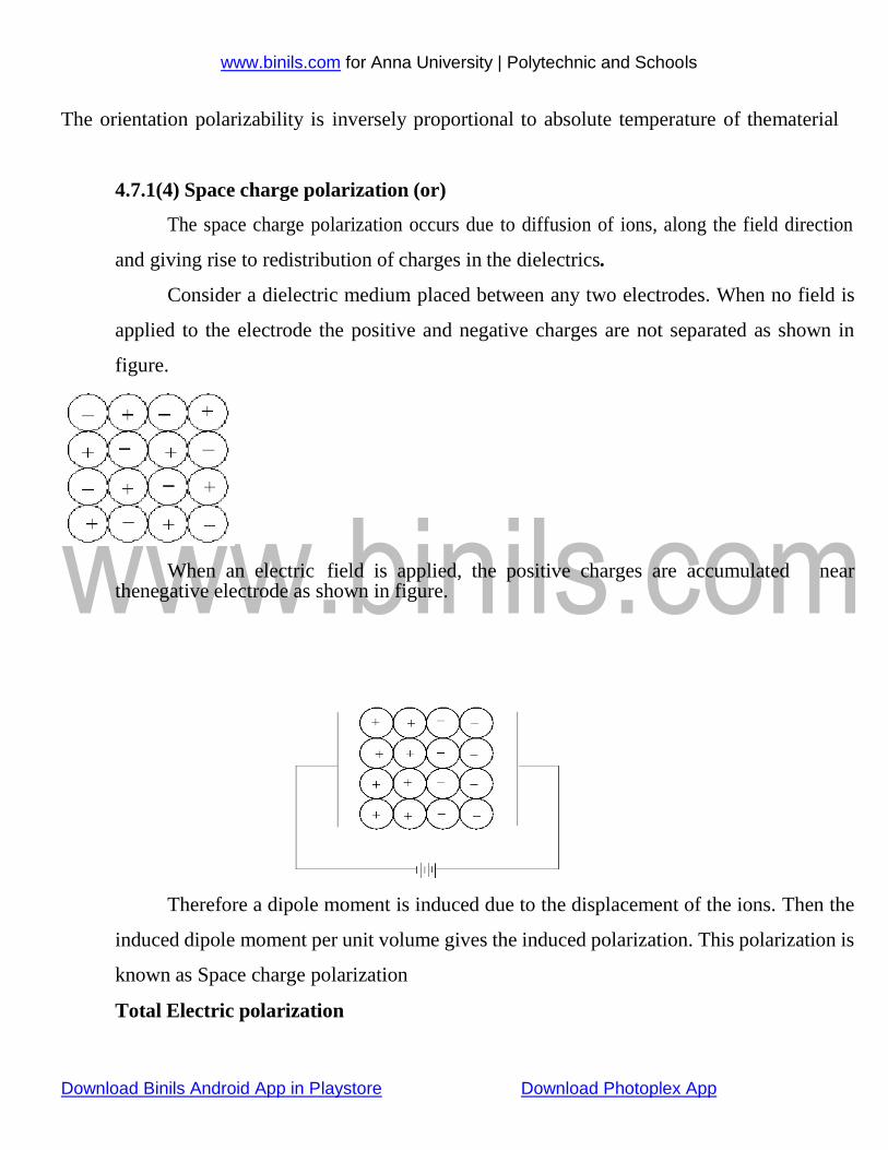
4.7.1(4) Space charge polarization (or)
The space charge polarization occurs due to diffusion of ions, along the field direction
and giving rise to redistribution of charges in the dielectrics.
Consider a dielectric medium placed between any two electrodes. When no field is
applied to the electrode the positive and negative charges are not separated as shown in
figure.
When an electric field is applied, the positive charges are accumulated near thenegative electrode as shown in figure.
Therefore a dipole moment is induced due to the displacement of the ions. Then the
induced dipole moment per unit volume gives the induced polarization. This polarization is
known as Space charge polarization
Total Electric polarization
www.binils.com for Anna University | Polytechnic and Schools
Download Binils Android App in Playstore Download Photoplex App
0
The Total Electric polarization is the sum of electronic polarization, ionic polarization, orientation
polarization, and space charge polarization. Among these, the space charge polarization is very
small compared to others. So it can be neglected
Therefore the total polarizability is given by
α = α e + α i + α 0
α = 4𝜋 ∈0 𝑅3 + 𝑒2
( 1
+ 𝜔2
1 ) + 𝜇2 ----- (1)
We know that the total polarizationis
𝑃 = 𝑁𝐸𝛼 ---------- (2)
Substitute equation (1) in (2) we get,
0 𝑚 𝑀
𝑒2 1
3𝐾𝐵𝑇
1
𝜇2
𝑃 = 𝑁𝐸 [4𝜋 ∈0 𝑅3 + 𝜔2
(𝑚
+ ) + 𝑀
] 3𝐾𝐵𝑇
This equation is called Langevin- Debye equation
![Time-Dependent Dielectric Breakdown in High-Voltage GaN MIS … paper.pdf · We also found evidence of pro-gressive breakdown (PBD) prior to final hard breakdown [7]. Fig. 1 shows](https://static.fdocuments.net/doc/165x107/5f52e924da7dff34614b6513/time-dependent-dielectric-breakdown-in-high-voltage-gan-mis-paperpdf-we-also.jpg)