
21, rue d’Artois, F -75008 PARIS B1-301 CIGRE 2014 http ...
15
Innovative insertion of very long AC cable links into the transmission network F. LESUR, P. MIREBEAU, M. MAMMERI, J. SANTANA RTE Nexans Silec Cable Prysmian France SUMMARY To ensure the safety of the electricity transmission in the south east area of France, a new network is being created using insulated cables at the 225 kV level, taking advantage of many innovations in the field of HV power cables. The installation of 110 km of three-phase circuits is in progress. In the report, the authors address the following points: • The reasons for choosing the technical solution based on 100% insulated cables, for the network safety improvement. o Management of losses, o Management of active and reactive power, o Load flow studies, o Protection system. • The cable system design, with special considerations to safety and cost efficiency ratio. o Cable design with special extruded and grounded semi-conductive outer skin, o Long unit length, o Accessories with special design care in case of internal or external fault. Preferred choice of dry accessories, short-circuit tests, and internal fault tests. o Direct cross bonding of joints. o Qualification tests. • The installation work with reduced environmental impact. o Trench design, o Ground thermal management, o Fault containment. The project started in 2009 and the commissioning date is expected in 2015. KEYWORDS Long HVAC cable system, cable design, semi-conductive outer skin, cable system tests, direct cross-bonding, trench design, fault containment. 21, rue d’Artois, F-75008 PARIS B1-301 CIGRE 2014 http : //www.cigre.org [email protected]
Transcript of 21, rue d’Artois, F -75008 PARIS B1-301 CIGRE 2014 http ...

Innovative insertion of very long AC cable links into the transmission network F. LESUR, P. MIREBEAU, M. MAMMERI, J. SANTANA RTE Nexans Silec Cable Prysmian
France
SUMMARY To ensure the safety of the electricity transmission in the south east area of France, a new network is being created using insulated cables at the 225 kV level, taking advantage of many innovations in the field of HV power cables. The installation of 110 km of three-phase circuits is in progress.
In the report, the authors address the following points: • The reasons for choosing the technical solution based on 100% insulated cables, for
the network safety improvement. o Management of losses, o Management of active and reactive power, o Load flow studies, o Protection system.
• The cable system design, with special considerations to safety and cost efficiency ratio. o Cable design with special extruded and grounded semi-conductive outer skin, o Long unit length, o Accessories with special design care in case of internal or external fault.
Preferred choice of dry accessories, short-circuit tests, and internal fault tests. o Direct cross bonding of joints. o Qualification tests.
• The installation work with reduced environmental impact. o Trench design, o Ground thermal management, o Fault containment.
The project started in 2009 and the commissioning date is expected in 2015. KEYWORDS Long HVAC cable system, cable design, semi-conductive outer skin, cable system tests, direct cross-bonding, trench design, fault containment.
21, rue d’Artois, F-75008 PARIS B1-301 CIGRE 2014 http : //www.cigre.org

INTRODUCTION The French southeast area (between Provence and French Riviera: Marseille-Toulon-Cannes-Nice) is characterized by the risky situation of a weakness in its transmission grid: poor local generation (10% of its own electricity consumption), a unique 400 kV "south road" to supply a dense populated area, and no possibility of 400 kV loop from the North. Overload at peak time occurs, more particularly in winter, and 400 kV overhead lines can be stopped due to forest fires and lightning in this dry Mediterranean region in summer. No sufficient alternative links could have been found for decades in this protected and touristic area, so much that this situation can lead to a blackout (up to 2.5 million people). A safety plan included three major improvements: the installation of renewable energy generators, a citizen action to promote energy consumption (residents are invited by sms to reduce their electrical use before critical peaks), and the development of new transmission lines. It was decided to build three sections, 100% underground with 225 kV insulated cables to reinforce the existing AC network [5]: Boutre-Trans (65 km), Biançon-Fréjus (25 km) and Biançon-La Bocca (17 km).
Fig. 1: Map of the project, southeast France The cable system design and the choice of the cable route must to take into account a rocky soil, high temperatures in summer, and high environmental issues. The use of existing infrastructures was preferred as far as possible.
Fig. 2: Example of singularities to be crossed with heavy cable drums
1

RTE (the French transmission system operator), cables manufacturers and civil engineer companies implemented many innovations to achieve this ambitious project. All the aspects – not only delivery lengths on drums – have been reviewed and processed to deal with very long AC cable links: Boutre-Trans (65 km) is a world first at this level of power (up to 800 MW). The project was made possible by solving two essential requirements: a significant reduction of cost to make the solution acceptable, and a duration as short as possible to minimize any effects for communities and residents. NETWORK STUDIES The integration of a very long underground cable circuit into the transmission network requires many detailed electrotechnical studies and simulations in both static and dynamic conditions. The insulated cable has different electrical characteristics compared to the equivalent length of overhead lines: higher capacity, lower inductance and characteristic impedance, lower propagation speed. A significant capacitive current can decrease the expected transmitted current rating, and the cables generate capacitive reactive power. The flowchart below describes the main studies performed at the early stage of the project:
Fig. 3: Flowcharts of grid studies It was decided to install a 80 MVAR shunt reactor at each end of the longest link (Boutre-Trans, 65 km) to compensate 60% of the reactive power generated by the cables. The use of oil immersed reactor enabled to reduce the floor space. The selection of the device was a technical compromise to limit the losses due to the capacitive current, to decrease the reactive power for high voltage issues in summer, and to keep enough reactive power for low voltage issues in winter at peak time.
Static behaviour (steady-state
analysis)
Current rating and reactive power compensation
analysis
Dynamic behaviour (slow)
Optimum reactive power flow, static
security N-1 analysis
Study of resonances
Fast transients, fault analysis, voltage
performance
Definition of mitigation measures
Specifications
Validated solution
Critical analysis (Ecole Polytechnique
de Montréal)
Study of protections
• Confirmed results of the static study
Critical analysis (CESI)
• Requirement of two 80 MVAR reactors
• No hazardous phenomenon
2

Time domain studies took into account pre-load cable energising and de-energising, cable fault clearance, and overhead line fault clearance in the vicinity, in order to finalise the high voltage equipment arrangement. CABLE DESIGN Conductor 2000 and 2500 mm² cross-sections are necessary to transmit the specified current rating, depending on the thermal environment, and eventually connected by transition joints. Cable losses are minimized by Milliken copper conductors with enamelled wires, reducing skin and proximity effects. Despite the unfavourable thermal conditions of the area, the high current rating (1600 A in winter, 1400 A in summer) can be achieved.
Fig. 4: Design and picture of enamelled copper 225 kV XLPE cable
Cable 2000 mm² Cu 2500 mm² Cu Thickness (mm) Diameter (mm) Thickness (mm) Diameter (mm)
Conductor 56 66 Insulation 18 96 18.5 111
Metal screen 1.25 105 1.25 116 Oversheath 5 115 6 130
Weight 26.4 kg/m 33 kg/m
Table 1: Dimensional characteristics of the cables The metal screen is a thick welded aluminium foil (Combined Design), bonded to HDPE outer sheath. A conductive outer coating (skin) is applied. This skin makes possible the sheath integrity test, maintenance checks and fault location test. Indeed, the main installation method over the cable route is using plastic pipes, isolating the outer sheath from the surrounding soil. The sheath integrity test is performed under 20 kV DC (15 min) after installation. The resistance of conductive skin must be less than 16 MΩ/m to allow for the detection of defects. It must be more than 580 Ω/m to avoid for large touching currents. The skin is grounded each time it can be seen and touched: at terminations and on each side of a joint in gallery. LONG UNIT LENGTH For many years the standard delivery length for underground EHV cable was in the range of 500 m, leading to about 30 t drums. This value was due to different limitations such as: capacity of equipment like take-up units, maximum power of test transformers, transportation
3

in terms of drum size and weight, in terms of access to site work and regulation, and technical restriction on the maximum standing voltages along the metal shield.
Induced voltage (V)
Summer : Ic = 1400A 205
Winter : Ic = 1600 A 235
Short circuit 31.5kA 9000
Table 2: Induced voltages for a length of 1450 m (longest section) In France the maximum allowed voltage of metal shield is 400 V where public access is prohibited. This particular feature of the French regulation makes possible the extension of unit lengths up to 2000 m and more, depending on the current rating and laying method.
Fig. 5: Example of difficult access for heavy big drums CROSS-BONDING DESIGN Another way to optimize the cost of underground power cable connections is to minimize the needed number of protections in joint bays along the route. This approach has been called “direct cross-bonding”. The use of longer delivery lengths as well as “direct cross bonding” method supposes that an accurate and thorough study of the electrical stress applied to joint shield break is carried out as part of the basic design of the link. Lightning strikes on OHL (overhead lines) are likely to cause the propagation of surge waves in underground links they are connected with. The magnitude of the over-voltages stressing the screen ends at cross-bonding locations decreases with the distance to the end of the underground cable link. As a consequence, the over-voltages in the midspans are likely to be lower than the withstand level at shield end in relating joints [1] [3] even if not protected by SVL (surge voltage limiter). Cross-bonding current design in France Sectionalised cross-bonding is currently used [2]. Cables are transposed to limit induced voltages in neighbouring networks. The screen interruptions are protected by surge arresters connected to the shield break joints through concentric bonding leads, maximum 10 m in length. These arresters are star connected, and the neutral point is grounded. They are located in a manhole, designed to contain the effect of an internal arcing. Up to now, the nominal voltage was limited to 6 kV and has been increased to 12 kV.
4
The withstand levels specified in the French standard NF C-33-254 [6] are given in Table 3. Regarding impulse levels, international recommendations from Cigré and IEC are given between brackets, if they are different. In addition, AC withstand levels are also required. Nominal voltage of the link (kV) 36/63 (72,5) 52/90 (100) 130/225
(245) 230/400
(420)
Lightning impulse voltage for main insulation (kVc) 325 450 1050 1425
Screen to ground impulse withstand level (kVc) 50 (30) 50 (37,5) 50 (47,5) 62,5
Impulse withstand level of screen interruption (kVc) 80 (60) 80 (75) 100 (95) 125
Screen to ground AC withstand level (kV) (15 min) 20 20 20 20
AC withstand level for screen interruption (kV) (15 min) 25 25 25 35
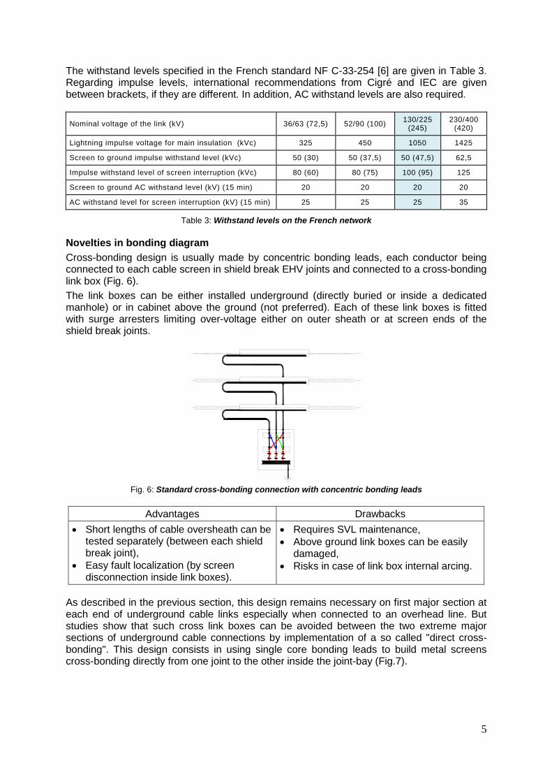
Table 3: Withstand levels on the French network Novelties in bonding diagram Cross-bonding design is usually made by concentric bonding leads, each conductor being connected to each cable screen in shield break EHV joints and connected to a cross-bonding link box (Fig. 6). The link boxes can be either installed underground (directly buried or inside a dedicated manhole) or in cabinet above the ground (not preferred). Each of these link boxes is fitted with surge arresters limiting over-voltage either on outer sheath or at screen ends of the shield break joints.
Fig. 6: Standard cross-bonding connection with concentric bonding leads
Advantages Drawbacks
• Short lengths of cable oversheath can be tested separately (between each shield break joint),
• Easy fault localization (by screen disconnection inside link boxes).
• Requires SVL maintenance, • Above ground link boxes can be easily
damaged, • Risks in case of link box internal arcing.
As described in the previous section, this design remains necessary on first major section at each end of underground cable links especially when connected to an overhead line. But studies show that such cross link boxes can be avoided between the two extreme major sections of underground cable connections by implementation of a so called "direct cross-bonding". This design consists in using single core bonding leads to build metal screens cross-bonding directly from one joint to the other inside the joint-bay (Fig.7).
5

Fig. 7: Direct cross-bonding connections In the case of the so called “direct cross bonding”, the reliability of the system is totally dependent on the integrity of the insulating shield break. The dielectric strengths, and the AC, impulse, and switching surge withstand levels of the interruptions have to be fixed in relation with the calculated magnitudes of AC and transient voltages in the circuit [8]. For very long links, in order to make possible the fault location, the link is divided in shorter segments, shield break joints being used for earthed joints. Each cable screen end inside the joint are connected to earth via bonding leads and a link box as shown in Fig. 8.
Fig. 8: Bonding to earth through link box using leads with possible disconnection
NEW CONCEPT FOR ACCESSORIES The number of joint bays of Boutre-Trans link is limited to 68, some drums weighting up to 50 t (1400 m of cable). The use of the direct cross-bonding system implies new types of accessory as shown on the sketch Fig.9. The shield break joint was successfully tested according to RTE Specification (0214) [7] sequence. The cable system was submitted to short-circuit test (31.5 kA / 0.5 s) followed by “Test of outer protection of the joint” (IEC 62 067 – Annex G) where the insulation of the shield sectionalizing was subjected to 100 kVp impulses and 25 kV AC power frequency voltage test (Table 3).
Fig 9: Schematic diagram of extra-long 225 kV cable line with direct cross-bonding sections
A
B C D X Y
Z
6

The mentioned link is 65 km long which is the worldwide longest 225 kV line related to power installed in the world. It connects an outdoor substation (A) to a GIS substation (Z). The general earthing scheme of the cable link corresponds to the cross-bonding of the cable screen as shown in Fig. 9. Unbalanced cross-bonding has been limited in order to optimize benefits from the reduction of the cable screen losses by compensation of the circulating current within the cable screen. At each end of the link, sections between B to C and X to Y a classical cross-bonding system was used. Sections between D and G use the direct cross-bonding system.
Three different types of joints and their associated hardware are used: • Earthing Joints. • Sectionalizing Joints to classical cross-bonding connections between B and C and
between X and Y: the screen ends are protected with SVL’s. They are intended to perform easy fault location, if any, using screen disconnection inside link boxes.
• Sectionalizing Joints with direct cross-bonding connections on the major part of the line between C and D and up to X: no SVL are provided for the protection of screen interruption against over-voltages.
• Straight joints have been implemented in order to optimize the earthing scheme. CABLE SYSTEM QUALIFICATION The whole cable system includes 2000 mm² and 2500 mm² 225 kV XLPE cable with thick welded aluminium foil, CB premoulded joint, GIS and composite outdoor terminations. The cable system has been successfully tested and qualified according to NF C 33-354 and RTE Specification. Electrical tests on complete cable system As mentioned above, depending on the thermal environment, two conductor sizes 2000 and 2500 mm² could be used. Such a configuration needs the implementation of a transition joint between the two cross-sections. In this context, the 225 kV XLPE cable system including the transition joint has been subjected to an “extended prequalification test”. The test has been performed in accordance with clause 13.3 of IEC 62067 Ed. 2011 and the following protocol was applied:
• Test voltage values, • Bending test on cables, • Partial discharge test at ambient, • Tan δ measurement, • 80 heating cycle voltage test under 2 U0, • Partial discharge test at ambient and high temperature, • Lightning Impulse Voltage test, • Short-circuit test (31.5 kA / 0.5 s), • Tests of outer protection for joint (Annex G) where the insulation of the shield
sectionalizing was subjected to 100 kVp impulses and 25 AC power frequency voltage test (Table 3).
• Examination of the cable system after completion of the above tests. The installation of the complete cable system subjected to the electrical tests has been installed taking into consideration both rigid and flexible configurations Fig. 10.
7

Fig. 10: Extended Prequalification tests on 225 kV Cable System including transition premoulded joint between 2000 mm² and 2500 mm² enamelled copper
Pulling tests In order to validate the maximum pulling force and the sidewall pressure on the cable avoiding any damage of the civil works during installation, the following protocol tests has been performed:
• Pulling tests (Fig. 11), • Electrical tests: PD measurement at 195 kV, AC test at 260 kV / 15 min, • Dimension measurements, • Visual inspection.
The tests were carried out successfully on a 2500 mm² enamelled copper cable where a maximum force of 10 000 daN was applied. The bending radius was 10 m. It is noted that the inner side of the duct was inspected through a mobile camera after pulling test and no sign of damage was observed. As expected, the result was satisfactory according to [4].
Fig.11: Pulling test on 2500 mm² enamelled copper simulating installation conditions
8

TRENCH DESIGN Previous underground cable installation on civil engineering sites in a close area showed that the rocky soil can lead to low performance of trench opening and to quick wear of machine tools. In order to face this issue on long distance cable installation and to avoid potential delays, RTE performed studies and selected preferential typical cross-section, whose feasibility was then validated by civil engineering companies. Regulatory requirements A French law, known as the Technical Decision of 17/05/2001, describes the technical conditions with which electric power networks must comply. Especially, underground cables must be protected against any damage that could occur due to soil compaction, the contact of hard materials and the hit of hand-held tools. In some constraints (rocky soil or the crossing of other networks), the load height above cables can be lower than 1.00 m, subject to effective mechanical protection. Local authorities (regulation of the road operator) clarify the rights and obligations of the actors of the public domain in order to reconcile the different stakes of public services. Roads are classified by their daily traffic and the conditions of roadway repair work are listed, including the height of cable covering. Fault containment behaviour French transmission cables are extensively installed in plastic ducts: polyvinyl chloride (PVC) thin ducts encased in concrete or high density polyethylene (HDPE) thick ducts directly buried. The first installation mode is used in urban sites, while the second is reserved for rural areas. A wide validation campaign was performed in 1998 at Les Renardières testing plant, and showed that sufficient thickness of HDPE duct can perfectly confine cable fault. This input data must be considered when optimizing the trench design, as a compromise with laying depth. Further tests are discussed in this paper. Mechanical strength during cable pulling Maximising cable length delivered on drums decreases the number of joints, thus reducing the global cost of the system and limiting the risk of potential weakness by moisture ingress. Studies of mechanical strength were performed in order to improve the pulling in ducts of long cable lengths. A maximum pulling stress of 10 000 daN was specified for copper large conductors. Current rating The immediate thermal environment of the cables trench has a strong impact on the maximum current rating. Therefore, the trench design (depth, materials, and compaction) and circuit geometry (axial distance between conductors) are essential parameters. The soil thermal management is discussed in this paper. Electromagnetic fields For a single circuit; the influent parameters are the current rating, the position of the conductors and the height of calculation or measurement. Special care is taken to promote and achieve favourable configurations (trefoil formation). The compaction of the circuit (spacing between cables) and laying depth are key factors to generate magnetic fields whose magnitude is well under the recommended value of exposure of general public (100 µT). Civil works The construction of the underground power line must be completed in less than two years.
9

The French way of cable laying (reference case below) has been giving a satisfactory feedback for about fifteen years. Several cases were studied to adapt the trench design to the specific constraints of the project and to lower the installation cost:
• While the regular ratio of the pipe internal diameter to the cable outer diameter is greater than 1.5, smaller duct size was applied.
• The depth was reduced by 30 cm to improve thermal transfer and to reach the specified current rating. The resulting height is lower than the limit (1.30 m) which makes compulsory the casing with planks to prevent from potential collapse, saving a considerable amount of time.
• HDPE ducts were preferred to thin PVC ducts in order to keep a good level of fault containment despite the reduced depth, to withstand the pulling of heavy long cable length, and to decrease the thickness of concrete around ducts.
These decisions contributed to a smaller and narrower trench, leading to lower volumes to excavate (key role in rocky soils), better efficiency of the operations, and decreased supply of materials for the backfill and cover.
Reference Optimised
Fig. 12: Cross-sectional view of installed cables and handling to connect ducts with sleeves The use of sleeve to connect the ducts in bars induces an over thickness at the connection. The consequences of the extra spacing between touching ducts in trefoil (about 40 mm) have been reviewed every time that the axial distance between conductors is an influent parameter (overall size, volume of materials, electromagnetic fields, mutual heating). SOIL THERMAL MANAGEMENT Cables are installed in southeast France, in an area where RTE applies soil thermal assumptions of warm conditions: 22°C in winter and 30°C in summer, including a 5°C safety margin to take into account the mutual heating of possible cables in parallel in the future. The soil thermal resistivity is considered as 0.85 K.m/W in winter and 1.2 K.m/W in summer. A special care is taken to prevent from any soil drying due to moisture migration initiated by
Backfill
Concrete
10

cable heating. The interface between soil and concrete embedding must be lower than 60°C in winter and 55°C in summer. The use of directly buried ducts was rejected due to this soil drying criterion (the resulting current rating was too low). The underground cable system is embedded with concrete, whose thickness (50 mm) around ducts has been optimized to get the best compromise between the thermal performance (concrete behaves as a controlled backfill), mechanical withstanding (load), and cost (excavation and volume of material supply).
Fig. 13: Thermal assumptions for the cable system design (project area in the green frame)
Iterative calculations between analytic elements (IEC standards) and finite element methods (FEM, software application Flux2D) have been performed to design the cable system, according to steady state operation and emergency (overload 5, 10 and 20 min) conditions. FAULT CONTAINMENT AND DUCT DESIGN Validation campaigns showed performance in terms of fault containment of different HDPE conduits for a short-circuit of 31.5 kA and different values of Standard Dimension Ratio (SDR: ratio of pipe outside diameter to wall thickness):
Installation SDR load height (m)
Short-circuit duration (ms)
Ducts directly buried 17 1.00 250
Ducts embedded in concrete 33 0.60 100
Test was very satisfactory, since the concrete block remained intact and the duct was not even perforated. The circular cross-section of the inner pipe was checked with the free passage of a gauging device (85% of cross-sectional surface).
Fig. 14: Safe duct and connection sleeve after short-circuit test
s
D
s D SDR =
Cold Intermediate Warm
11

The underground cable system will be protected by two differential protections. It is assumed that the extremely low probability of a combined failure of the circuit-breaker and an internal cable fault at full fault current makes the assumption of the maximum short-circuit duration of 100 ms realistic. The use of thinner HDPE ducts (SDR = 33 instead 17) saves approximately half the cost of ducts. Since the weight of SDR 33 ducts is twice lighter, plastic ducts can be handled into the trench more easily. Then, the assembly of 12 to 18 m bars with connection sleeve requires no specific tool. For high SDR (thin large conduits), the risk of ovalization (the cross-section becomes elliptic under external pressure constraints) must be studied, as well as the risk of buckling for long duct bars. It was decided to use spacers every 4 m for SDR 33 and 6 m for SDR 17, considering that the over thickness of connection sleeves are natural spacers. A special care is taken to strap the system in trefoil at every spacer. The minimal radius of bending also depends on SDR. A value of 35 times the value of the duct external diameter is used for SDR 17. Due to the lack of feedback with SDR 33 ducts, a value of 50 times the duct external diameter was selected on the basis of an expert manufacturer opinion. When the cable route includes sharp turns, a duct of adequately low SDR must be preferred.
Fig. 15: Ducts in trefoil formation with connecting sleeves and spacers
WITHSTAND ABILITY TO COMPRESSIVE FORCES A study was performed in order to check the durability of the civil engineering including HDPE ducts and concrete, under the effect of rolling loads, static or dynamic, isolated or spread, for various locations of installation: under roadway, under the side of a pathway, or under natural ground. It concluded that the durability of the system can be achieved without reinforced concrete, and the concrete formulation could have been established to withstand the compressive forces, wherever the trench is opened. The over cost of this concrete of better mechanical strength is only a few euros per metre. The best location of the trench is at the middle or on the right side of the rolling lane, when administrative authorizations can be obtained. The thickness of concrete around the ducts – and especially the lower layer, as an apron – conditions the integrity of the system. Measures must be implemented during the filling of the concrete into the trench in order to ensure the minimal thickness. In addition to the mechanical strength, concrete contributes to heat dissipation and current rating performance.
12

The use of connection sleeves (inducing an extra space between ducts) involves limiting the size of the concrete aggregates to improve the filling of the space between conduits and to prevent any weak points. Furthermore, during the concreting operations, ducts are subject to Archimedean buoyancy force: a weighting device must be provided to ensure the proper vertical positioning of the ducts in the concrete. ON-SITE MANUFACTURE OF HDPE DUCTS For the first time in France, a mobile polyethylene extrusion line was installed close to the cable route to produce continuous lengths of ducts. Three teams of two people took turns to produce the first set of 120 km of ducts, extruded from 1160 t of raw materials. The plastic pipes were cut into bars of 8 - 8.5 m bars in order to make the handling into the trench easier (9 kg/m).
Fig. 16: Extrusion line of HDPE ducts: extrusion head in a container / cooling line under a tent
Four days were required to install the manufacturing plant. Ten weeks were planned to complete the expected components. Despite a few unexpected hazards which delayed the production, the economic balance with a conventional supply of this first was reached. The lesson learned should make significant savings with future projects. However, for this first section of 40 km of the project, only 39 trucks were used instead of 100, 125000 km and 128 t of CO2 were saved.
Fig. 17: Mobile manufacturing plant
13

CONCLUSIONS The strategic need of improving the safety of the southeast French grid has required the use of large conductors with enamelled copper: 2000 mm² for standard laying and 2500 mm² for singular sections with potential hot spots. It was decided to install a 80 MVAR shunt reactor at each end of the longest link (Boutre-Trans, 65 km) to compensate 60% of the reactive power generated by the cables. The use of 50 t drums made possible the delivery of 1400 m cable lengths thus limiting the number of joint bays. The French maximum allowed voltage of metal shield is 400 V where public access is prohibited, which enables the management of the induced voltages. The withstand of shield break joints is 25 kV and the withstand of surge arresters was doubled to 12 kV. The maximum pulling stress of cables in ducts was increased to 10 000 daN. These factors contribute to decrease the number of joints by one-third, improving the reliability of the system. The direct cross-bonding made possible a 75% saving for the bonding system with the suppression of the intermediate link boxes, with the overview of reduced maintenance.
The optimized trench design made possible: • a 35% reduction of waste excavated materials, a 45% reduction of filler materials, the
exemption of casing with planks and shoring up, • lighter ducts for an easier installation, a 25% saving on their supply, a lower
environmental impact (35% reduction of plastic materials, less CO2), • the required current rating, excluding the risk of soil drying, • maximum magnitude of electromagnetic fields (≤ 30 µT) at 1 m above the ground
surface, well under the recommended 100 µT value for general public exposure, despite the high current rating (1600 A in winter),
• a 15% saving on civil works and a 50% gain in speed compared with standard methods of installation.
BIBLIOGRAPHY [1] A. GILLE & al: “Double 150 kV link, 32 km long, in Belgium: design and construction”,
2004 Cigré report B1-305. [2] E. DORISON & al: “400 kV underground links for bulk power transmission. New
developments in the field of XLPE insulated cables”, 2000 Cigré paper 21-105. [3] Cigré Technical Brochure 283 “Special Bonding of High Voltage Cable”, October 2005. [4] Cigré Technical Brochure 446 “Advanced design of metal laminated coverings:
Recommendation for tests, guide to use, operational feedback”, WG B1.25, February 2011.
[5] M. SURDON: WET’S 2011 – paper 1.1. [6] French standard NF C 33-254: “Insulated cables and their accessories for power
systems”. [7] French Specification R-TECH-CNER-SETP-LS-05-00214. [8] D. DUBOIS & al: “Evolution in method and performance for bonding the metal screen of
UG HV power cable”, Jicable 2011 paper B10.4.
14


![21, rue d’Artois, F-75008 PARIS - cigre.org.br · Mrs. Martinato, Mr. Miethke, Mr. Asano, Mr. Alaor, Dr. Knorr, Mrs. Höhlein [3] Copper Strip Corrosion Standards – ASTM Method](https://static.fdocuments.net/doc/165x107/5b8ee41c09d3f2c7748b8dbe/21-rue-dartois-f-75008-paris-cigreorgbr-mrs-martinato-mr-miethke.jpg)


