Teleprotecio CIGRE
172
Cigré JWG 34/35.11 PROTECTION USING TELECOMMUNICATIONS Joint Working Group 34/35.11 December 2000
description
tele protección cigre
Transcript of Teleprotecio CIGRE

Cigré JWG 34/35.11
PROTECTIONUSING
TELECOMMUNICATIONS
Joint Working Group 34/35.11
December 2000

PROTECTION USING TELECOMMUNICATIONSCIGRE JWG 34/35.11
2 / 172
Protection using Telecommunications
Cigré Joint Working Group 34/35.11
- Final Report -
Regular members of JWG34/35.11:
Per Odd GJERDE (Convenor) (Norway)
Hermann SPIESS (Secretary) (Switzerland)
Alastair ADAMSON (United Kingdom)
Ken BEHRENDT (United States)
Michael CLAUS (Germany)
Alouis W. H. GEERLING (Netherlands)
José Angel GONZALES VIOSCA (Spain)
Christopher HUNTLEY (Canada)
Carlos SAMITIER OTERO (Spain)
Yoshizumi SERIZAWA (Japan)
Kent WIKSTROM (Sweden)
Corresponding members:
Ricardo de AZEVEDO DUTRA (Brazil)
Stephen HUGHES (Australia)
David C. SMITH (South Africa)
Comments and contributions received from:
Hervé HOUKE (France)
Trygve JORDAN (Norway)

PROTECTION USING TELECOMMUNICATIONSCIGRE JWG 34/35.11
3 / 172
Contents1 FOREWORD, SCOPE, OBJECTIVE ..............................................................................................................7
2 POWER SYSTEMS AND FAULT CLEARING .............................................................................................9
2.1 ELECTRIC POWER SYSTEMS ..............................................................................................................................92.2 ELECTRIC POWER SYSTEM FAULTS AND CLEARING........................................................................................12
2.2.1 Electric Power System Faults ................................................................................................................122.2.2 Fault Clearing .......................................................................................................................................13
2.3 WHY DOES PROTECTION NEED TELECOMMUNICATION? ..................................................................................152.4 INTRODUCTION TO POWER SYSTEM PROTECTION ...........................................................................................15
2.4.1 Fault clearing system.............................................................................................................................172.5 HOW IS TELECOMMUNICATION USED..............................................................................................................19
3 PROTECTION USING TELECOMMUNICATIONS .................................................................................21
3.1 LINE PROTECTION ...........................................................................................................................................213.1.1 Analog Comparison Schemes ................................................................................................................21
3.1.1.1 Current differential protection ........................................................................................................................... 223.1.1.2 Phase comparison protection ............................................................................................................................. 283.1.1.3 Charge comparison protection ........................................................................................................................... 31
3.1.2 State Comparison Schemes....................................................................................................................333.1.2.1 Intertripping Underreach Distance Protection ................................................................................................... 343.1.2.2 Permissive Underreach Distance Protection ...................................................................................................... 363.1.2.3 Permissive Overreach Distance Protection ........................................................................................................ 373.1.2.4 Accelerated Underreach Distance Protection..................................................................................................... 383.1.2.5 Blocking Overreach Distance Protection ........................................................................................................... 393.1.2.6 Deblocking Overreach Distance Protection ....................................................................................................... 40
3.2 BUSBAR PROTECTION......................................................................................................................................423.2.1 Two-breaker busbar configuration........................................................................................................42
3.2.1.1 Normal fault clearing......................................................................................................................................... 423.2.1.2 Breaker failure ................................................................................................................................................... 43
3.2.2 One- and a half breaker busbar configuration ......................................................................................433.2.2.1 Normal fault clearing......................................................................................................................................... 443.2.2.2 Breaker failure ................................................................................................................................................... 45
3.2.3 Two zones / one breaker configuration..................................................................................................463.2.3.1 Normal fault clearing......................................................................................................................................... 46
3.3 OTHER PROTECTION SCHEMES ........................................................................................................................473.3.1 Generator protection .............................................................................................................................473.3.2 Transformer protection..........................................................................................................................473.3.3 Reactor protection .................................................................................................................................48
3.4 SYSTEM PROTECTION ......................................................................................................................................483.4.1 Back-up protection ................................................................................................................................493.4.2 System-wide protection..........................................................................................................................53
4 TELECOMMUNICATION SYSTEMS FOR PROTECTION ....................................................................55
4.1 TELECOMMUNICATION CIRCUITS ....................................................................................................................564.1.1 Private and rented circuits ....................................................................................................................564.1.2 Analogue and digital circuits.................................................................................................................56
4.2 TELECOMMUNICATION NETWORKS.................................................................................................................574.3 TRANSMISSION MEDIA....................................................................................................................................58
4.3.1 Pilot wires / Copper wires .....................................................................................................................584.3.2 Power Line Carrier (PLC).....................................................................................................................604.3.3 Microwave Radio...................................................................................................................................62
4.3.3.1 Multichannel radio............................................................................................................................................. 634.3.3.2 Single channel radio .......................................................................................................................................... 64
4.3.4 Optical fibres .........................................................................................................................................654.3.5 Satellites ................................................................................................................................................67
4.3.5.1 GEO - Geosynchronous Earth Orbit Satellites................................................................................................... 67

PROTECTION USING TELECOMMUNICATIONSCIGRE JWG 34/35.11
4 / 172
4.3.5.2 MEO - Medium Earth Orbit Satellites ............................................................................................................... 684.3.5.3 LEO - Low Earth Orbit Satellites ...................................................................................................................... 68
4.4 MULTIPLEXING TECHNIQUES AND DIGITAL HIERARCHIES..............................................................................694.4.1 Multiplexing Techniques........................................................................................................................69
4.4.1.1 Frequency Division Multiplexing (FDM).......................................................................................................... 694.4.1.2 Time Division Multiplexing (TDM) .................................................................................................................. 704.4.1.3 Code Division Multiplexing (CDM).................................................................................................................. 71
4.4.2 Digital Hierarchies................................................................................................................................724.4.2.1 PDH - Plesiochronous Digital Hierarchy........................................................................................................... 724.4.2.2 SDH - Synchronous Digital Hierarchy .............................................................................................................. 73
4.5 NETWORK TECHNOLOGIES..............................................................................................................................754.5.1 Transport Networks ...............................................................................................................................774.5.2 Service Networks ...................................................................................................................................78
4.5.2.1 Circuit Switched Networks (POTS, ISDN) ....................................................................................................... 794.5.2.2 Packet Switched Networks (X.25, Frame Relay)............................................................................................... 804.5.2.3 Cell Switched Networks (ATM)........................................................................................................................ 804.5.2.4 Datagram Networks (IP)................................................................................................................................... 81
4.5.3 Local Area Networks .............................................................................................................................824.5.3.1 Topology............................................................................................................................................................ 834.5.3.2 Media Contention and Protocols........................................................................................................................ 844.5.3.3 Advanced topologies ......................................................................................................................................... 85
4.6 NETWORK DESIGN AND OPERATION ...............................................................................................................864.6.1 Introduction ...........................................................................................................................................864.6.2 Technological considerations................................................................................................................88
4.6.2.1 PDH/SDH Networks.......................................................................................................................................... 884.6.2.2 ATM Networks.................................................................................................................................................. 894.6.2.3 IP Networks ....................................................................................................................................................... 91
5 TELEPROTECTION INTERFACES ............................................................................................................93
5.1 CONTACT INTERFACES ....................................................................................................................................935.2 ANALOG INTERFACES......................................................................................................................................94
5.2.1 Pilot-wires (50/60Hz) ............................................................................................................................945.2.2 Voice frequency circuits (2-wire/4-wire) ...............................................................................................94
5.3 DIGITAL DATA INTERFACES.............................................................................................................................945.3.1 Electrical interfaces...............................................................................................................................945.3.2 Optical fibre interfaces ..........................................................................................................................955.3.3 LAN / Ethernet interfaces ......................................................................................................................96
6 PERFORMANCE AND RELIABILITY REQUIREMENTS ......................................................................99
6.1 REQUIREMENTS ON TELECOMMUNICATION SYSTEM........................................................................................996.1.1 Introduction ...........................................................................................................................................99
6.1.1.1 Terminology and General Requirements ......................................................................................................... 1006.1.1.2 Definitions ....................................................................................................................................................... 103
6.1.2 Requirement from analog comparison protection ...............................................................................1086.1.2.1 Time synchronization through GPS................................................................................................................. 1086.1.2.2 Time synchronization through communication network.................................................................................. 108
6.1.3 Requirements from state comparison protection .................................................................................1096.1.3.1 Propagation Time............................................................................................................................................. 109
6.1.4 Requirements from intertripping .........................................................................................................1096.1.5 Requirements from system protection..................................................................................................110
6.2 REQUIREMENTS ON TELEPROTECTION ...........................................................................................................1116.2.1 Requirements on interface compatibility .............................................................................................1126.2.2 Functional requirements......................................................................................................................112
6.2.2.1 Analog comparison protection control and monitoring ................................................................................... 1136.2.2.2 State comparison protection control and monitoring ....................................................................................... 1136.2.2.3 Erroneous signal detection............................................................................................................................... 1146.2.2.4 Loop-back and misconnect detection............................................................................................................... 1146.2.2.5 Actions on alarm conditions ............................................................................................................................ 114
6.3 REQUIREMENTS ON PROTECTION...................................................................................................................115

PROTECTION USING TELECOMMUNICATIONSCIGRE JWG 34/35.11
5 / 172
6.3.1 Requirements on analog comparison protection .................................................................................1156.3.1.1 Need for delay compensation .......................................................................................................................... 115
6.3.2 Requirements on state comparison protection.....................................................................................1166.3.2.1 Interface co-ordination..................................................................................................................................... 1166.3.2.2 Delay Compensation........................................................................................................................................ 116
6.3.3 Requirements on other protections......................................................................................................1166.4 CONSIDERATIONS ON INTERFACES AND INSTALLATION PRACTICES...............................................................116
7 PROTECTION SYSTEM CONFIGURATIONS AND DESIGN ..............................................................119
7.1 PROTECTION SCHEMES AND TELECOMMUNICATION SYSTEMS COMPATIBILITY ............................................1197.2 DESIGN CHECKLIST .......................................................................................................................................124
7.2.1 Application ..........................................................................................................................................1247.2.2 Interfaces .............................................................................................................................................1247.2.3 Contractual..........................................................................................................................................125
8 FUTURE TRENDS AND PROBLEMS TO BE SOLVED..........................................................................128
8.1 TRENDS IN COMMUNICATION........................................................................................................................1288.1.1 General Network Development............................................................................................................1288.1.2 Transport Technologies.......................................................................................................................1288.1.3 Networking Technologies ....................................................................................................................1298.1.4 Service Access/Provisioning Technologies..........................................................................................1298.1.5 Integration of Technologies.................................................................................................................1298.1.6 New Technologies for QoS provision ..................................................................................................1308.1.7 Intra- and inter-substation communication .........................................................................................131
8.1.7.1 Intra-substation communication....................................................................................................................... 1318.1.7.2 Inter-substation communication....................................................................................................................... 132
8.2 TRENDS IN PROTECTION................................................................................................................................1348.2.1 Considerations on new protection philosophies ..................................................................................134
8.3 OPEN ISSUES AND PROBLEMS TO BE SOLVED.................................................................................................1378.3.1 Protection relay interoperability .........................................................................................................137
9 CONCLUSIONS.............................................................................................................................................139
ANNEX A1 TELEPROTECTION SYSTEM CONFIGURATIONS ............................................................141
ANNEX A2 TELECOMMUNICATION SYSTEMS CHARACTERISTICS ..............................................144
ANNEX A3 QUALITY OF SERVICE.............................................................................................................146
A3.1 INTRODUCTION TO QOS............................................................................................................................146A3.2 QOS DEFINITION IN ATM NETWORKS.......................................................................................................147
A3.2.1 ATM Service Categories..................................................................................................................149A3.2.2 ATM over SDH/SONET...................................................................................................................151A3.2.3 Applications Summary.....................................................................................................................152
A3.3 QOS DEFINITION IN IP NETWORKS............................................................................................................152A3.4 IP TO ATM SERVICE MAPPING..................................................................................................................155A3.5 QUALITY OF SERVICE STANDARDS ...........................................................................................................156
ANNEX A4 PROTECTION SYSTEM TIME SYNCHRONIZATION TECHNIQUES.............................157
A4.1 TIME SYNCHRONISATION FOR SIMULTANEOUS SAMPLING.........................................................................157A4.1.1 Internal timing synchronization ......................................................................................................157A4.1.2 External timing synchronization .....................................................................................................159
LIST OF FIGURES.................................................................................................................................................161
LIST OF TABLES...................................................................................................................................................163
BIBLIOGRAPHY ...................................................................................................................................................164

PROTECTION USING TELECOMMUNICATIONSCIGRE JWG 34/35.11
6 / 172
ABBREVIATIONS..................................................................................................................................................166
INDEX......................................................................................................................................................................169

PROTECTION USING TELECOMMUNICATIONSCIGRE JWG 34/35.11
7 / 172
1 FOREWORD, SCOPE, OBJECTIVEDeregulation in both the telecommunication and electric power industry, together with newtelecommunication network technologies and advances in numerical protection, has resulted inthe need to reconsider traditional methods of delivering teleprotection schemes and theirassociated bearer services. Fibre-optic technology is commonly deployed in newtelecommunication networks for inter-station communication, and utility-owned and publictelecommunication networks from third parties are available for protection purposes. Trends insubstation automation move towards the use of bus- and LAN technologies within substationsand interchange of information in numerical form. Numerical protection has been state-of-the-artfor protection relaying for some years.
In September 1996, Cigre SC34 "Power System Protection and Local Control", and SC35"Power System Communication and Telecontrol", decided to form the joint working group CigréJWG 34/35.11, with the following scope of work:
- Assess the state of development of advanced protection using inter-site communications- Analyze the relevance and opportunities of newly released telecommunication
technologies (referring to the work of WG 35.07)- Identify and promulgate opportunities for future advances in the joint discipline of
teleprotection- Examine the need for, and if necessary compile, a lexicon of terminology to suit the new
environment- Develop a new report to update the Technical Brochure Ref. No. 13, 1987.
JWG 34/35.11 met for a kick-off meeting in Oslo in September 1997. The working group agreedthat a new version of the former Technical Brochure "Protection systems usingtelecommunication" (Ref. No. 13, 1987) should be produced. The document should createawareness for the requirements, opportunities and risks of protection systems usingtelecommunications, and guide protection and telecommunication engineers towards a commonunderstanding for the design and operation of reliable teleprotection schemes that meetperformance requirements in the most economical way.
This Technical Brochure has the following content:
Chapter 2 describes power systems from a teleprotection point of view, with focus on powersystem faults, their reasons and characteristics, and fault clearing requirements. It continueswith the definition of fault clearing systems, protection systems, protection schemes, and endsup with explanations why teleprotection is needed, and how protection can usetelecommunication to meet fault clearing requirements.
Chapter 3 describes protection relaying principles and protection schemes usingtelecommunications, and deals - from a power system point of view - with various aspectsaround the need of teleprotection, its benefits and adverse implications if the teleprotectionservice would fail.
Chapter 4 gives an overview of telecommunication systems, with focus on capabilities andlimitations related to protection signal transmission. Problems and risks that may arise withdifferent types of telecommunication technologies are addressed, and functional and reliabilityaspects are dealt with, both under normal conditions and - most important - under power system

PROTECTION USING TELECOMMUNICATIONSCIGRE JWG 34/35.11
8 / 172
fault conditions.
Chapter 5 deals with interfaces. Requirements on interfaces between protection, teleprotectionand telecommunication devices are given.
Chapter 6 focuses on performance requirements on protection, teleprotection andtelecommunication functions.
Chapter 7 deals with protection system configuration and design. Compatibility issues betweenprotection schemes and telecom technologies are addressed to provide a guide for protectionand telecommunication specialists to design teleprotection systems that will meet fault clearingrequirements.
Chapter 8 gives an outlook on future trends and addresses some problems to be solved.
In Chapter 9 the document is summarized some conclusions are drawn.
Annexes A1 to A4 contain some related topics and additional information, which the JWG hasfound valuable for the better understanding of the subject.

PROTECTION USING TELECOMMUNICATIONSCIGRE JWG 34/35.11
9 / 172
2 POWER SYSTEMS AND FAULT CLEARING
2.1 ELECTRIC POWER SYSTEMSElectric power systems consist of three principal components: generating stations, transmissionsystems, and distribution systems. Generating stations convert mechanical or thermal energy toelectric energy, typically in the form of 50 or 60 Hz alternating current. Transmission systemstransmit electric energy from the generating stations to the distribution system. To transmitelectric energy efficiently over long distances, transmission system power lines are typicallyoperated at 200 kV to 800 kV. The operating voltage of generators and distribution systems istypically in the range of 2.4 kV to 25 kV. Electric power systems deliver electric energy to powerconsuming equipment owned by residential, commercial, industrial, and governmentalcustomers. Consumer products typically operate at several hundred volts. Power transformersare required to step the power system voltage up and down to connect various power systemsegments having different system operating voltages.
Power lines designed to transmit electric energy, called transmission lines, are often networkedto improve service capability and reliability. This permits lines to be taken out of service forplanned maintenance, or forced out of service by fault clearing, without disrupting the delivery ofelectric energy from the generating source to the customer. Branches of the network areconnected at nodes, called busbars or buses. Power systems are almost always three phasesystems, including conductors for 3 phases and ground wires. Throughout this report only singleline diagrams are shown. Some simple busbar configurations are shown in Figure 2.1-1 andFigure 2.1-2.
Node in network = busbar
Overhead power line
Breakers
Generator andtransformer unit 2
Generator andtransformer unit 1
Overhead power line
Underground or submarine
cable Breakers
Figure 2.1-1: Single-line diagram of a typical power station
Nodes at different voltage levels are connected by transformers. These connection points,transformers and other units are made within a limited geographical area, called a station.

PROTECTION USING TELECOMMUNICATIONSCIGRE JWG 34/35.11
10 / 172
Configuration of a typical power generating station is shown on Figure 2.1-1, and Figure 2.1-2shows a typical transformer station.
Node in network = busbar
Transformer 2
Breakers
Load
Power lines/cables
Transformer 1
Overhead power line
Underground or submarine
cable
Overhead power line
Breakers
Figure 2.1-2: Single line diagram of a typical transformer station
Power flows through all healthy transmission lines in the electric power system network as itmoves from generation sources to consuming equipment owned by customers. Electric powersystem networks operated by more than one electric power utility are often tied together to forma large grid that supports the transmission of power over a very large area, sometimes spanningseveral countries. Figure 2.1-3 shows the routes of major power lines connected in theScandinavian power grid.

PROTECTION USING TELECOMMUNICATIONSCIGRE JWG 34/35.11
11 / 172
/ 50 100 150 kmVNHA
FLENSBURG
TORNEHAMN
NARVIK
LETSI
AJAURE
GRUNDF.
LINN-VASSELV.
PETÄJÄSKOSKI
PIKKARALA
PIRTTIKOSKI
ALAJÄR VI
ALAPITKÄ
HUUTOKOSKIPETÄJÄVESI
ALTA
JÄRP-STRÖMMEN
O
ULVILA
HYVINKÄÄHIKIÄ
KANGAS-ALA
EN-KÖPING
BORG-VIK
HASLE
RJUKAN
V
OSLO
GÖTEBORGNÄSSJÖ
NEA
STORFINNF.
INKOOHELSINKI
LOVIISA
TJELE
KARLSHAMN
FINNLAND
[04/ \
TOIVILA
VUOLIJOKI
HJÄLTA
DCDC
KRISTIANSAND
ISLAND
KARLSHAMN
HAMNOSKARS-
NORRKÖPING
OLKILUOT
ORNORRFORSST
OFOTEN
TRONDHEIM
MALMÖ
BERGEN
RING-HALS
HELSING-BORG
KøBEN-
TUNNSJØDAL
(132)
TROMSØ
SVARTISEN
REYKJAVIK
STAVANGERSTOCKHOLM
KASSØ
LISTA
HAMBURG
DEUTSCHLAND
NORWEGEN
SCHWEDEN
Figure 2.1-3: The Scandinavian Power Grid

PROTECTION USING TELECOMMUNICATIONSCIGRE JWG 34/35.11
12 / 172
2.2 ELECTRIC POWER SYSTEM FAULTS AND CLEARING
2.2.1 Electric Power System FaultsPower system conductors energized to extremely high voltages in three phase systems must beproperly insulated from each other and from ground. This insulation is achieved by specialinsulation materials covering each conductor and/or by air insulation. Air is a very inexpensiveinsulator, but requires very large spacing. Special non-conducting materials typically insulate theenergized conductors in generators, transformers, capacitors, reactors and cables wherecompact design is essential. Overhead power lines are insulated by air, except at the point theyare attached to the supporting poles and towers. Special insulators made of porcelain, glass, orinsulating plastic with special surface design and shape achieve the combination of strengthand electric insulation to make this attachment. Overhead line design principles are shown inFigure 2.2-1 which also indicates possible arc fault tracks.
Ground wires
The three phase conductors
Phase - Ground fault
Phase - Ground fault
Phase - Phase fault
Ground
Tower
Insulator
Figure 2.2-1: Power line with examples of fault types and fault positions
All power system components are exposed to faults due to insulation breakdowns. TheScandinavian power system shown in Figure 2.1-3, for instance, typically experiencesapproximately 3000 faults per year.
Voltage stresses caused by lightning and switching transients, and contamination due topolluted air are major sources of insulation breakdowns. Mechanical stresses caused by wind,vibration, ice, and snow-loading are major sources of insulator and supporting structure damagethat also leads to insulation breakdown.
For power lines, most insulation breakdowns are in air between phases and/or phases andground. Most frequently, insulation breakdowns are along the surface of insulators due toexcessive voltage stresses. An example of insulator flashover is shown in Figure 2.2-2

PROTECTION USING TELECOMMUNICATIONSCIGRE JWG 34/35.11
13 / 172
A flashover in air influences a few rather narrow ‘corridors'where the air loses electrical insulation capabilities. The airdoes not recover its insulation capability as long as thecurrent is flowing. Therefore it is very important to interruptthe fault current as soon as possible to recover insulationcapability. When the current is interrupted, air recovers it’sfull insulation capability within a fraction of a second. If thefault current is interrupted rather fast, normally no damageis caused to conductors, insulators or towers. Then thepower line can be re-energized within a short time so it canagain carry power in the grid.
One of the most important design and operational criteriafor a power transmission system is that the power systemshould withstand tripping of at least one power line (unit)without any unnecessary interruption of consumers orpower producing units.Wide area weather disturbances, like lightning storms,severe wind storms, and ice storms, expose multipletransmission lines to the risk of faults within the same timeperiod. Consequently, high speed tripping and fast re-closing of tripped transmission lines may be very importantto avoid power system collapse due to two or more powerlines out of service at the same time.
Faults on power apparatus like breakers and units likegenerators, transformers and cables are most probablybreakdowns and damage of special insulation materials.This causes damage that must be repaired before the unitcan be re-energized to carry power. This may take aconsiderable length of time, depending on the availabilityof spare parts, and trained service personnel. Sometimesunits are completely destroyed and must be replacedbefore normal operation can be achieved.
Faults on both power lines and other power units can alsobe caused by misoperation of earth switches and "forgotten" security ground connections.
Power system faults caused by weather, animals, high trees, humans, or equipment failuredisrupt normal power flow by diverting current through a short-circuited connection andcollapsing power system voltage. In addition to equipment damage, power system faults causetransients that adversely affect sources of generation and customer loads. Consequently, faultsmust be detected and isolated very quickly. Electric power system generators, transformers,busbars, and power lines are therefore monitored by protective relays designed to detect powersystem faults and operate isolating devices designed to interrupt damaging fault current.
2.2.2 Fault ClearingPower system fault clearing requirements are very important design and operational criteria forpower systems. Faults can cause damage that requires expensive repair work or investmentsfor equipment replacement. Faults also cause severe operational disturbances. Generators
Figure 2.2-2: Insulator flashover

PROTECTION USING TELECOMMUNICATIONSCIGRE JWG 34/35.11
14 / 172
accelerate, motors retard and severe voltage drops can easily result in tripping of complexindustrial plants. For the power system itself, severe disturbances can result in collapses andblackout for regions, and, in severe cases, even for several countries. Today’s society does notaccept frequent severe disturbances and blackouts because of their heavy reliance on electricpower consuming devices for business activities, safety, lighting, heating, cooking,communication and many other conveniences.
Therefore, to avoid severe disturbances and blackouts, sound protection practices are used toprovide rapid fault clearing. In some cases, formal requirements for fault clearing are provided toassure consistent levels of reliability levels throughout the power system. Formal requirementsmay be grouped in external requirements and utility requirements as already done in [3].
External requirements may encompass:- Customer power quality and interruption requirements.- Requirements from insurance companies who underwrite equipment failures.- Legal requirements to meet ‘prudent utility practice and industry standards’ in case
primary equipment failures result in personal injury or property damage and legal actionsare taken against the utility by the parties incurring damage.
- International and national safety regulations, imposed by governmental and otheragencies.
- Requirements imposed by manufacturers of primary equipment in order to validateequipment warranties.
- Requirements from occupational safety and hazard prevention.
Utility requirementsThe power system must be designed and operated to avoid instability, loss of synchronism,voltage collapse, undesired load shedding, and unacceptable frequency or voltage. Goodprotection practices help meet these objectives by detecting and clearing faults rapidly. Rapidfault clearing helps:
- Prevent severe power swings or system instability- Minimize disruption of system power transfer capability- Prevent unreliable services- Limit or prevent equipment damage
It is very important to clear the fault within specified ‘limits’ to ensure that the healthy remainderof the power system can continue to serve it’s customers with acceptable quality and reliability.
Requirements on protectionProtection performance requirements are issued to satisfy external and utility requirements.These requirements specify how protective schemes must perform on specific contingencies tofulfill external and utility requirements. They typically provide a balance between the conflictinggoals of dependability and security. Dependability goals require maximum sensitivity and fastresponse time to detect and clear all faults quickly with very low probability of a failure to trip.Security goals require maximum selectivity and slow response time to minimize the probabilityof an unwanted trip on an unfaulted circuit. Security is an issue during fault conditions as well asduring normal, unfaulted conditions.
Simply stated, the implementation of these protection requirements should result in dependableoperation of only those relays protecting the faulted unit, and secure non-operation of the relaysduring non-fault conditions and when faults occur on adjacent power system units. This balanceis met only through proper protection scheme design, proper relay and equipment selection,

PROTECTION USING TELECOMMUNICATIONSCIGRE JWG 34/35.11
15 / 172
and proper connection and setting of these relays and equipment to achieve appropriatesensitivity and coordination.
When protection schemes detect a fault on the equipment or line they protect, they signalisolating devices, called circuit breakers, to open, isolating the faulty segment of the system,and restoring normal system voltage and current flow in the power system.
Protection schemes command circuit breakers to isolate faults with no intentional time delay.When the protection scheme and circuit breakers operate properly, the fault is isolated withinthe required fault-clearing time. Protection applied on high voltage systems, where fault-clearingtimes are most critical, typically detect faults and operate in about one to two cycles. Someschemes operate in less than one cycle. Circuit breakers operate in one to three cycles. Thecombination of high-speed protection schemes and fast circuit breakers can interrupt a fault inabout two cycles, although more common fault-clearing times range from three to six cycles.
2.3 WHY DOES PROTECTION NEED TELECOMMUNICATION?Protection systems must meet sensitivity, time response, selectivity and reliability requirementsin order to meet fault clearing requirements. Fault clearing systems (see 2.4.1) for generators,busses, transformers or other units within a substation can normally meet these requirementswithout using telecommunication. Telecommunication may be needed for the protection of thesesubstation units only if a breaker is missing or fails to interrupt fault-currents.
Protection schemes for extremely high voltage transmission lines, however, very seldom meetall these requirements without using telecommunications. Some protection schemes, such asstand-alone step-distance schemes, provide very reliable and sensitive protection capable ofclearing all power system faults without using telecommunications, but time response and/orselectivity requirements can only be met by using telecommunications. Telecommunications aretherefore needed to ensure that time response and selectivity requirements are met for allpower system fault conditions! Telecommunications is also essential for some types ofprotection schemes, like analogue comparison schemes, to operate.
If telecommunication fails, backup protection schemes ensure that power system faults will becleared, but they may not be cleared within specified performance requirements. Then theprobability of uncontrollable power swings and partial or complete system blackout increasessignificantly. Alternative methods for reducing the probability of fault-induced blackouts is tobuild additional generating stations and transmission lines, or add redundanttelecommunications. In virtually all cases, it will be far less expensive to add redundanttelecommunications. Telecommunications is therefore vital to the reliability and economy ofmodern electric power systems.
2.4 INTRODUCTION TO POWER SYSTEM PROTECTIONPower system protection schemes are designed to detect and clear faults, in accordance withrequirements on protection, as discussed in the previous sub-chapter, to:
- Minimize adverse affects on customer loads- Minimize disruption of system power transfer capability- Coordinate tripping with protective relays in other protection zones- Prevent severe power swings or system instability- Limit or prevent equipment damage
Power units and lines are protected in zones to coordinate fault detection and clearing. A
PROTECTION USING TELECOMMUNICATIONSCIGRE JWG 34/35.11
16 / 172
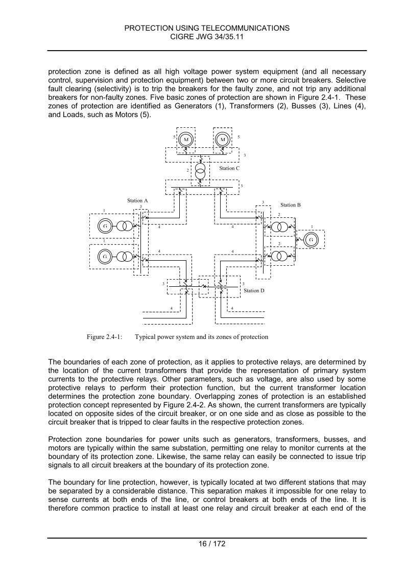
protection zone is defined as all high voltage power system equipment (and all necessarycontrol, supervision and protection equipment) between two or more circuit breakers. Selectivefault clearing (selectivity) is to trip the breakers for the faulty zone, and not trip any additionalbreakers for non-faulty zones. Five basic zones of protection are shown in Figure 2.4-1. Thesezones of protection are identified as Generators (1), Transformers (2), Busses (3), Lines (4),and Loads, such as Motors (5).
G
Station A
G
G
M M
Station B
Station C
Station D
1
1
1
4
4
4
4
4
3
33
3
2
2
2
3
55
4
3
Figure 2.4-1: Typical power system and its zones of protection
The boundaries of each zone of protection, as it applies to protective relays, are determined bythe location of the current transformers that provide the representation of primary systemcurrents to the protective relays. Other parameters, such as voltage, are also used by someprotective relays to perform their protection function, but the current transformer locationdetermines the protection zone boundary. Overlapping zones of protection is an establishedprotection concept represented by Figure 2.4-2. As shown, the current transformers are typicallylocated on opposite sides of the circuit breaker, or on one side and as close as possible to thecircuit breaker that is tripped to clear faults in the respective protection zones.
Protection zone boundaries for power units such as generators, transformers, busses, andmotors are typically within the same substation, permitting one relay to monitor currents at theboundary of its protection zone. Likewise, the same relay can easily be connected to issue tripsignals to all circuit breakers at the boundary of its protection zone.
The boundary for line protection, however, is typically located at two different stations that maybe separated by a considerable distance. This separation makes it impossible for one relay tosense currents at both ends of the line, or control breakers at both ends of the line. It istherefore common practice to install at least one relay and circuit breaker at each end of the

PROTECTION USING TELECOMMUNICATIONSCIGRE JWG 34/35.11
17 / 172
line. These relays may operate independently, or they may share information to improve theiroperating speed, or they may require communication between them to operate.1
CT for Zone B
CT for Zone A
Zone A Zone B
CT for Zone B
CT for Zone A
Zone A Zone B
b. both CTs on same side of breaker
a. CTs on opposite sides of breaker
Figure 2.4-2: Overlapping protection zones established by current transformer location
2.4.1 Fault clearing systemA Fault Clearing System is defined in this report according to Figure 2.4-3. Fault currents mustbe interrupted from both (all) sides. The fault clearing system therefore includes :
- Protection system- Mechanisms of circuit breakers
Fault Clearing System includes one or more protection systems and the circuit breakersrequired to clear (interrupt) a fault and isolate the faulted portion of the circuit.
Protection System includes a complete arrangement of protection equipment and otherdevices required to achieve a specified function based on one protection principle. A protectionsystem is all embracing and includes protection functions as well as auxiliary power systems,sensors for detecting measured quantities, controls and circuitry for closing/opening circuitbreakers, teleprotection and telecommunications for interchange of information betweenprotective functions and all necessary connections between these functions and units.(Example: A phase comparison protection system, or a line current differential protectionsystem.)
Sensors include voltage transformers and current transformers that scale primary systemvoltages and currents down to secondary values compatible with the protective device design.
The Teleprotection Function converts the signals and messages from the protection functioninto signals and messages compatible with the telecommunication system, and vice versa. Theteleprotection function may be integrated with the protective device, or the telecommunicationequipment, or it may be in a stand-alone device.
The Telecommunication System provides a communication link between ends of a protected 1 Protection schemes that share information to improve operating speed are sometimes referred to as “non-unit” protection
schemes. Protection schemes that require communication to operate are sometimes referred to as “unit” protection schemes.

PROTECTION USING TELECOMMUNICATIONSCIGRE JWG 34/35.11
18 / 172
circuit, permitting the exchange of information (analogue data and/or status) or transmission ofcommands. In Figure 2.4-3, the telecommunication system may be dedicated point-to-point,shared point-to-point, or a network.
Mech-anism
High Voltage Equipment
Fault Clearing System
Protection System
Auxiliary power
Protection Functions
Teleprotection Function
Control
Sensors
TelecommunicationSystem
Teleprotection Function
Mech-anism
Protection Functions Control
Circuit Breaker
Auxiliary power
Sensors
Circuit Breaker
ProtectionScheme
Protection Zone
Figure 2.4-3: Fault clearing system
Protection Function(s) may be performed by multiple protective relays working together, ormore commonly in modern protection systems, by one or more multi-function protective relays.

PROTECTION USING TELECOMMUNICATIONSCIGRE JWG 34/35.11
19 / 172
Protection functions in one station interchange information with protection functions in a remotestation via teleprotection and telecommunications. This sub-total functionality forms aProtection Scheme.
2.5 HOW IS TELECOMMUNICATION USEDTelecommunication is essential for analog comparison protection schemes (see 3.1.1) to sharedata between relays at each end of the protected line. Telecommunication is needed for directintertripping schemes to pass tripping commands from the protection and control scheme at oneline terminal to the power circuit breaker at the other line terminal. Telecommunication is usedwith state comparison protection schemes (see 3.1.2) to reduce the overall tripping time forfaults on the protected line section.
Analog comparison protection schemes typically share data, such as line current magnitudesand phase angles, to differentiate between power system faults within the protected zone oroutside the protected zone. Communication between relays at each line terminal is essential tothe operation of analog comparison protection schemes. State comparison protection schemesshare the logical status of relay elements to determine if the fault is internal or external. Theseschemes are generally built by adding and interfacing communication to stand-alone relays toimprove tripping speed for faults in the end-zone areas not protected by direct tripping relays.Schemes that use communication to improve tripping speed are referred to as communicationassisted schemes.
Telecommunication is also used for intertripping schemes that must communicate a tripcommand to a remote substation circuit breaker to isolate a fault within the local station, blockand control schemes, and wide area protection schemes. All of these schemes are described ingreater detail in Chapter 3. Telecommunication systems used for protection are described inChapter 4.
Protection using telecommunication provides consistent relay tripping times in the order of 2 to 3cycles for faults over the entire length of a protected transmission line. Stand-alone protectionschemes may take upwards of 20 to 30 cycles to trip both line terminals of a faulted line.Protection schemes using telecommunication can thereby reduce the tripping and clearing timefor line faults by as much as 18 to 28 cycles compared with stand-alone protection schemes.This reduced tripping time greatly reduces the affect of faults on generators, power transfer, andcustomer loads, and reduces the damage to faulted and unfaulted equipment. The faster faultclearing speeds are essential to the efficient and economic operation of modern power systems.
As described in this document, protective relays are interfaced with telecommunication systemsthrough the teleprotection function. The teleprotection function may be performed by a stand-alone device, or it may be integrated with the protective relay or with the telecommunicationequipment. Interfaces between protection relays, teleprotection, and telecommunicationsystems are described in Chapter 5.
The following chart is excerpted from the IEC 60834-1 standard to help show the relationshipbetween protection, teleprotection, and telecommunication.From the teleprotection point of view, the relatively selective protection schemes shown inFigure 2.5-1 are typically communication-aided state comparison schemes (see 3.1.2), and theabsolutely selective protection schemes in Figure 2.5-1 are typically communication dependentanalog comparison-schemes (see 3.1.1.).

PROTECTION USING TELECOMMUNICATIONSCIGRE JWG 34/35.11
20 / 172
Figure 2.5-1: Fundamental terms on protection and teleprotection(From IEC60834-1)

PROTECTION USING TELECOMMUNICATIONSCIGRE JWG 34/35.11
21 / 172
3 PROTECTION USING TELECOMMUNICATIONS
3.1 LINE PROTECTION
3.1.1 Analog Comparison SchemesAnalog comparison protection is based on the transmission and comparison of electricalparameters such as primary currents (amplitude and/or phase) between the ends of a protectedline. Each end sends its registered values to each other and compares them with the remoteones. When an internal fault occurs, the result of the comparison will be a differential value, sothat, if it is higher than a threshold, the relay will initiate the trip.
These systems are called analogue comparison protection systems because they exchangeanalogue quantities such as amplitude and/or phase with the other ends. They are sometimesalso referred to as "unit protection" or "closed" schemes. The term “unit” refers to the clearinterdependence between the ends for operation and to the closed and absolutely selectivecharacteristic of this protection.
Obviously, the comparison must be made between magnitudes at the same instant, whichimplies a transmission and comparison system as fast as possible. A delay must be provided forthe local signal to compensate for the transmission time of the remote value.
Unlike the time-grade protection such as distance and time overcurrent relays, the trip of theanalog comparison protection is instantaneous for every fault on the protected line.
It is applicable to any overhead line or cable at all voltage levels and for any type of systemneutral arrangement. It is particularly suitable where:
- Step distance relays (without acceleration schemes) have limitations, for example:� Very short lines and cables due to their low impedance, which makes it difficult to
find an adequate setting to get a instantaneous trip for faults on the main part of theline.
� Multi-terminal lines, since the intermediate infeeds modify the impedance seen bythe distance relays, which depends not only on the distance to the fault, but also onthe infeed from the remote terminals, making impossible an accurate measure of theimpedance.
- No potential transformers and only current transformers are installed at each end of theline.
We can distinguish two types analog comparison protection systems: longitudinal currentdifferential protection and phase comparison protection. The current differential protectioncompares the power frequency signals proportional to the primary power system currents(amplitude and phase angle), while the phase comparison one is based on comparison of thephase angle (or sign) between currents of each end of the protected line.
Since both of them use only current information, in comparison with the distance or othersystem protections, analog comparison protections have the following advantages:
- Not responsive to system swings and out-of-step conditions- Unaffected by inadvertent loss-of-potential (i.e., due to a blown potential fuse)

PROTECTION USING TELECOMMUNICATIONSCIGRE JWG 34/35.11
22 / 172
- No mutual coupling problems from parallel lines. This may cause the line-to-ground faultcurrent reverses and flows into a weak source terminal, causing faulty directionaldiscrimination if other protection systems are used
- Not subject to transient problems associated with coupling capacitor potential devices- With segregated current differential there are no problems of phase selection for single
pole auto-reclosing at simultaneous faults on different circuits and phases close to oneline end, because it operates only for faults between current transformers in each phase.
- Some relaying problems in EHV transmission lines due to applying series capacitors arealso overcome, e.g. voltage reversal, current inversion or phase imbalance.
When phase selection is required for single phase tripping, especially at simultaneous faults ondifferent circuits and phases or in a faulty line when handling heavily loaded EHV lines, thephase-segregated technique is used. The analogue information is transmitted separately foreach phase.
In cases where the complete information about the polyphase conditions is not essential andsingle-phase tripping is not needed, the non-segregated technique is used. It reduces the three-phase system of currents to a single-phase one by means of a mixing device. Thecommunication link needs therefore to only accommodate the transmission of this single phaseinformation. Some mixing techniques are described in [1].
3.1.1.1 Current differential protection
Operating principlesAs mentioned above the current differential protection is an absolutely selective protectionsystem for transmission lines, tripping instantaneously for faults in the protected zone defined bythe current transformers of each end of the line.
It is based in the principle of current comparison. The Figure 3.1-1 shows a basic scheme of thedifferential protection. In each terminal, an evaluation circuit compares the sum of the local andremote current values, i.e. the differential current, with an operation threshold value Iop. Innormal operation conditions or external faults, the current entering at one end is practically thesame as one leaving at the other end, so the differential current value is practically zero and theprotection will remain stable. For a fault on the protected power line the differential current valuewill exceed the operation value and the protection will trip.
When very large currents flow through the protected zone for a fault external to the zone adifferential current appears due to the different ratio error and saturation characteristic of thecurrent transformers, which could exceed the operation level. Such a maloperation of theprotection is prevented by the stabilizing. The stabilizing characteristic uses a bias current,which is usually proportional to the sum of the absolute values of the currents at each terminal,i.e. |iA| + |iB|, in order to make the protection less sensitive for higher through currents. Thistechnique is also called percentage restraint.

PROTECTION USING TELECOMMUNICATIONSCIGRE JWG 34/35.11
23 / 172
SA TX
RX+
Id>Iop
IAA
iB
DEL
SA
+
Id>Iop
iBTX
RX
DELiA
iA
IB B
Telecommunicationsystem
SA = Signal adapter (filtering, mixing circuit, A/D conversion, etc.)TX = TransmitterRX = ReceiverIop = Operation threshold according to stabilizing characteristicDEL = Delay compensationTPF = Teleprotection Function
Id IdTPF TPF
Figure 3.1-1: Principle of differential protection
Figure 3.1-2 shows an example of percentage restraint characteristic with two slopes: the lowerslope ensures good sensitivity to resistive faults under heavy load conditions, while the higherslope is used to improve relay stability against saturation of the current transformers and otherdistortion effects under heavy through fault conditions.
The selection of the minimal operation current Is1 is based upon the magnitude of linecapacitance current and switching transients expected on the protected line. The capacitance ofthe three conductors to earth and, except in single core cable, also between each other, makesthat under undisturbed conditions the current at both ends differs in angle and magnitude.Particularly in cables, the capacitive charging current can attain significant values. Nevertheless,usually the necessary rise of the Is1 does not involve an important loss of sensitivity.
Idiff
Ibias
slope k1
slope k2
TRIP
NO TRIP
Is1
Is2
Idiff = iA + iB
Ibias = |iA| + |iB|
Idiff > k1xIbias + Is1
Idiff > k2xIbias - (k2-k1)Is2 + Is1
Figure 3.1-2: Differential protection: Example of percentage restraint characteristic

PROTECTION USING TELECOMMUNICATIONSCIGRE JWG 34/35.11
24 / 172
The differential principle may be applied to multi-terminal lines. The protection relies on the sumof the inflowing currents, which are added geometrically. For this purpose, the measuringcircuits have to be so arranged that at each end of the line, the local current and the currentsfrom each of the others ends of the line are available for comparison. Generally, the most recentdesigns allow up to three terminals applications.
For a multi-terminal system, the master/slave or centralized configuration is also used. In thiscase, the current values are sent to a specific terminal for evaluation of the differential current.This terminal will henceforth be noted as a master, while the terminal sending information aboutcurrents will be denoted as a slave terminal. For a two-terminal system, the master/slaveconfiguration can, of course, also be used, but a master/master or distributed configuration,where the current information is exchanged between both terminals and evaluated at both endsis normally preferred, since this gives a shorter operating time than that in a master/slaveconfiguration. See Figure 3.1-4 and Figure 3.1-5 for more details about centralized anddistributed configurations.
The saturation of the current transformers for heavy through currents normally requires theselection of a higher slope setting which involves a loss of sensitivity for internal faults. Recentprotections include some techniques to detect the saturation, so in only such conditions is theprotection desensitized increasing the restraint slope. To avoid the maloperation of the remoteprotections, the terminal that detects the saturation includes a code in the message transmittedto the other ends, so that all terminals increase the degree of stabilization.
Time delay compensationAs mentioned, the current values used in the differential protection must be taken at the sameinstant at all ends of the power line for comparison, so a delay circuit is needed to compensatethe transmission time for the remote values. Classical designs incorporate an adjustable delayfor aligning the current values. However, when digital communication systems with automaticroute switch are used, the time delay can change and the protection must continuously adjustthe time alignment. For this purpose, digital devices incorporate different techniques in whichthe messages of current values sent through the communication channel are tagged with thesampling time. The principles of some synchronization techniques are described in more detailin A4.1. An error in delay compensation results in a differential current that - according to Figure3.1-2 - increases the risk of unwanted tripping. For more information see 6.1.2.2 and 6.3.1.1.
Additional functionsGenerally, differential protections use intertrip functions, i.e. the sending of trip commands to theremote ends. Intertrip commands are sent through the same communication channels used totransmit the current values (switching the channel frequency to a specific intertrip frequencywhen analogue links are used, or flagging the corresponding command bits in the out-goingdata messages in digital links).
The intertrip function is activated either when the relay reaches a trip decision, or by closing anexternal contact connected to an input of the relay.
The intertrip function can be used for:- Breaker failure protection- Stub protection: this is applied in switchyards with 1½ circuit breaker configuration.
Operating an input by external contact when the line isolator opens allows to protect theline between the circuit breakers and the line isolator.

PROTECTION USING TELECOMMUNICATIONSCIGRE JWG 34/35.11
25 / 172
Telecommunication systems used for differential protection
Differential protection systems using pilot wires for 50/60Hz signalsPilot wires connect both ends electrically and establish a differential circuit where the secondaryquantities may be in the form of current signals or voltage signals, which are proportional to theprimary current. Accordingly, there are two basic methods of creating a differential circuit,current balance or voltage balance. Figure 3.1-3 shows a basic scheme of a current balancedsystem using three pilot wires.
Evaluation circuitEvaluation circuit
MCTMCT
ST
TR TR
ST
MCT = Mixing current transformerTR = Transformer for trippingST = Transformer for stabilizing effect
Pilot wires
Figure 3.1-3: Basic scheme of a current balanced system using three pilot wires
In this case, the three-phase system is converted into a single AC current in the mixingtransformer MCT (non-segregated).
One differential system for each power phase (segregated) of the protected circuit can also beprovided. If high resistance faults are expected or faults on which the value of earth fault currentis relatively low, a fourth measuring system for the zero sequence component can beintroduced. This however, increases the number of pilot wires and therefore the communicationcost of the comparison information.
In both methods, a replica of the vector difference is formed at each line end by means of atransformer ST for the stabilizing effect and a replica of the vector sum of the currents flowing ateach end by means of a further transformer TR for the tripping effect. These values areevaluated separately at each line end in a measuring module and a tripping command is issuedto the circuit-breaker when the fault current has exceeded a permanently adjusted thresholdvalue.
Where the voltage induced into the pilot cables during earth faults may exceed the rated values,the protective relays should be isolated from the pilot wires by isolating transformers, which canalso be used to subdivide the total length of the pilot wires into two or three sections. Thisprevents the equipment from being subjected to excessive longitudinal voltage due to

PROTECTION USING TELECOMMUNICATIONSCIGRE JWG 34/35.11
26 / 172
interference. In any case, the grounding conditions should be considered.
The application of differential protection using pilot wires is restricted on lines up to 10-25 kmdepending upon the scheme used. So for longer lines, modulation techniques over othertransmission media should be used. More details about differential protection using pilot wiresand their limitations can be found in [1] and in chapter 4.3.1.
Differential protection systems using modulation or coding techniquesModulation or coding techniques that are compatible with analog and digital telecommunicationcircuits are used to overcome some of the shortfalls experienced with direct pilot wire coupling.1Typical techniques that are used:
- Frequency modulation (FM) for analog voice frequency (VF) channels.The instantaneous current values at each terminal are transmitted as analoguequantities to the other terminals in a voice frequency band (0.3 to 3.4 kHz) usingfrequency modulation. Whatever transmission media for analogue voice channels maybe applied.
- Numerical coding for digital telecommunication systemsThe instantaneous current values at each end of the power line are sampled, convertedto digital data and transmitted towards the other terminals through a digitaltelecommunication system. Sample rates ranging from 12 to 60 samples per cycle havebeen used.Normally, the telecommunication system is shared with other services like voice,telecontrol, etc. using Time Division Multiplexing techniques (see 4.4.1.2). The protectionsystem is connected to the PCM) multiplexer through standard interfaces. The mostcommonly used electrical interfaces are those contained within the ITU-T or EIArecommendation and are described in 5.3.1 and in [2].
- Dedicated optical fibres.Direct optical fibre links between protection terminals are also used. A higher reliability isachieved because intermediate devices are eliminated. However, when using dedicatedfibres over long distances, the cost can be prohibitive beyond 10-20 km. See 4.3.4 formore information on optical fibres.
Multi-terminal configurationTransmission line protection based on a current differential scheme detects zone faults by usingeach terminal current and transmits the detection results of the zone fault to the other terminals.There are two types of multi-terminal current differential protection configurations; centralizedand distributed configurations. As these configurations are applied to a single zone protection,they may be also applied to multi-zone and wide-area protections. 1 Note on pilot-wire replacement:
The corrosion problems of buried copper wires, with the trend of telcos to replace copper-pair cables with fibre communicationlinks, have put pressure on utilities to consider alternate means of connecting their extensive infrastructure of pilot-wire relays; thishas created a market for specialized interface units which emulate these copper wires.The accuracy requirements of such interfaces depend on the accuracy requirements of the relay settings, the main parameters ofconcern are:- The interfaces’ dynamic range. This should not limit on fault currents, whilst providing the required signal integrity during low
line-current conditions.- The end-to-end propagation delay. Since a 10% fault current error would be caused by the 5 degrees phase error accruing
from 230µs on a 60Hz grid (280µs on a 50Hz grid), this delay is critical (this teleprotection application has the most stringentdelay requirements of all teleprotection applications).
- In practice, up to 1ms may be manageable for the protection of 2-ended lines, but 500us or less may be required for 3-endedlines.

PROTECTION USING TELECOMMUNICATIONSCIGRE JWG 34/35.11
27 / 172
Centralized configurationFigure 3.1-4 shows an example of line protection for a five-terminal EHV line [7]. Each terminalhas a terminal unit that detects the current and transmits the data to the main unit terminal via acommunication channel. This configuration simplifies the unit of each terminal andcommunication channel. Since the main unit has current data of all terminals, the fault locatorfunction can be easily implemented by using these data.
Figure 3.1-4: Centralized configuration
Distributed configurationFigure 3.1-5 shows a distributed configuration of five-terminal current differential line protectionsystem. Each terminal has the current differential protection function as well as the signaltransmitting function that multiplexes current data at each terminal into one communicationsignal. Master station A sends its own current data to slave station B. Slave stations B, C, D andE multiplex their own current data over communication signal. Slave station E turns back thissignal toward slave station D. Now current data of all terminals are on the communication busand available for protection. In addition, this system contains sampling synchronization functionwhich enables the simultaneous sampling of current data at each terminal with high accuracy.Many installations were conducted using a 1.544-Mbit/s fiber-optic communications channel forHV double-circuit multi-terminal (up to ten terminals) or tapped lines [8]. In this networkconfiguration where current differential calculation is usually carried out at each terminal, acentralized scheme where only master station conducts the calculation and sends the transfertrip signal to all slave stations is also available.
Figure 3.1-5: Distributed configuration

PROTECTION USING TELECOMMUNICATIONSCIGRE JWG 34/35.11
28 / 172
3.1.1.2 Phase comparison protection
Operating principlesPhase comparison protection is based on the comparison of the phase angle between currentsof each end of the protected power line. Under normal load conditions or in case of an externalfault, the angle measured between the local current and the current at the remote ends will besmall. If the angle is large, it is due to an internal fault.
The basic principle of all phase comparison systems is to measure the angle as abovementioned. However, the method of doing so can differ from manufacturer to manufacturer. Aphase comparison system can be characterised by the following features:
- Comparison is made for each phase separately. A zero sequence circuit may also beincluded => Segregated protection.
- The currents of the three phases are mixed into one quantity for comparison => Non-segregated protection.
- The measurement is made twice every period => Full-wave phase comparison.- The measurement is made once every period => Half-wave phase comparison.- The phase angle signal is transmitted to the remote end only when a starter has picked
up.- Measuring is carried out continuously and the signals are permanently transmitted.- A phase comparison scheme can be designed for a blocking mode or for an unblocking
mode of operation, similar to a distance protection system using telecommunication.
The current which is used in the comparison is converted into a square wave signal, so that thepositive portion corresponds to the positive half-cycle and the zero portion corresponds to thenegative half cycle. The square wave from the remote terminal is compared with the localsquare wave as shown in Figure 3.1-6.
SA TX
RX∆ϕ>θ
IAA
iB
DEL iA
IB B
Telecommunicationsystem
SA = Signal adapter (mixing circuit, filtering, etc.)SQ = SquarerTX = TransmitterRX = ReceiverDEL = Delay compensation∆ϕ = Coincidence angleθ = Stabilizing angle
SQ
&
SATX
RX ∆ϕ>θiA
DELiB
SQ
&
& = Logical AND
TPF TPF
TPF = Teleprotection Function

PROTECTION USING TELECOMMUNICATIONSCIGRE JWG 34/35.11
29 / 172
∆ϕ<θ
IA
IB
iA
iB
a) External fault or normal load
∆ϕ>θ
IA
IB
iA
iB
iA & iB
b) Internal fault
Half-wave phase comparison
iA & iB
Figure 3.1-6: Phase comparison operating principles
In normal line conditions, there is a (small) phase current difference between line ends due to:- The capacitance of the power line- Errors due to the equipment, e.g. current transformers, sequencer, filters, squarer, etc.- The time delay due to the signal propagation time between the terminals
To prevent false trips, a critical angle is defined, commonly called stabilizing angle, which limitsthe maximum phase difference between currents, which would correspond to a boundarybetween tripping and stabilizing.
In a non-segregated phase comparison protection, the three currents are mixed into onequantity by means of a composite sequence network. The half-wave system use starters,normally based on overcurrent detectors, to determine whether a fault has occurred, to initiatesignal transmission to the remote end and to permit local tripping. In the full-wave system, thecomparison is made for each semi-period and normally is therefore faster than the half-wavetype. Phase comparison information is transmitted all the time to the remote equipment, and nostarter is required.
The comparison in the segregated protection system is similar to the non-segregated protectionbut, the comparison is made separately for each phase. It is very suitable for single polereclosing when handling heavily loaded EHV lines and parallel circuits on the same towers.Segregated protection is more sensitive for earth faults than non-segregated protection, but it ismore costly and the requirements on communication are higher.
More details about non-segregated and segregated techniques can be found in [1].

PROTECTION USING TELECOMMUNICATIONSCIGRE JWG 34/35.11
30 / 172
Some recent designs use dynamic principles based on the variation of the instantaneouscurrent values in for example two periods, i.e. ∆i = i(t) - i(t-2T), so that the signal to compare isthe sign of this variation value ∆i. This principle, normally operating in combination with aconventional phase comparison with starter, gives a higher sensitivity for high resistance groundfaults.
Time delay compensationAs described for differential protection system, time delay compensation must be also providedin phase comparison protection in order that phase current values can be compared at thesame instant. Depending on the technology, the channel delay can be compensated either bydynamic measuring techniques, or by a fixed delay setting in the protection relay. This latercase is only useful when there is no possibility for time delay variations.
Additional functionsA number of complementary functions may be included in the protection relay. Intertrip functionsare used to trip the remote breakers by means of sending a command through the samecommunication channel used for comparison signals. An overcurrent criterion normallysupervises the remote trip to prevent tripping under normal conditions.
The same additional functions mentioned for current differential protection are also applicablefor phase comparison protection.
Telecommunication systems used for phase comparison protection
Non-phase-segregated techniqueIn a half-wave comparison scheme it is very common to use power line carrier ascommunication medium, with the same carrier frequency used for both directions. The carrier isamplitude modulated i.e. switched “on” during positive half-cycles, and “off” during negative half-cycles, or vice-versa. This system operates as a blocking scheme. For an internal fault, if theblocking signal from the other end is not received, the output of the comparator circuit sends atrip command when the starters have picked up. This system might behave incorrectly in somesituations due to the noise generated during a fault, i.e. blocking the operation for internal faults(=> delayed tripping) or deblocking for external faults (=> unwanted tripping).
In a full-wave comparison different frequencies for the two directions must be used. A FSK(frequency shift keying) signal is used, which can be transferred over pilot wires, power line,radio or fibre-optic link. The communication equipment continuously monitors itself and when afault occurs, the local signal is compared with the remote for both positive and negative half-cycle in the protection relay.
Phase-segregated techniqueIn this case, the values of each phase are transmitted separately via independent channels.Most recent phase comparison systems usually operate in segregated mode and use digitalcommunication systems. The square signals to compare are sampled and converted to digitaldata, which are transmitted serially to the opposite terminal by the telecommunication system.Data rates and electrical or optic interfaces are the same as those mentioned for differentialprotection.
When starters are used to initiate the comparison, a sequence of “guard” bits is transmitted in

PROTECTION USING TELECOMMUNICATIONSCIGRE JWG 34/35.11
31 / 172
normal state of operation, in order to monitor the channel availability and performance by thereceiver.
Some designs optionally include a modem to interconnect two terminals through a 4-wire audiochannel. In this case, a data rate of 9'600 or 19'200 bit/s may be used.
3.1.1.3 Charge comparison protectionCharge comparison is based on the principle of conservation of charge at a node. The chargeentering one line terminal must be approximately the same as the charge leaving the other lineterminal(s) of a healthy transmission line. This is also the principle from which Kirchoff’s CurrentLaw (the theoretical basis of current differential relaying) is derived.
To perform charge comparison, the waveform of each line terminal’s phase and residual currentis sampled every ½ millisecond. The half-cycle area under each wave is measured byintegrating current samples between zero-crossings. For each phase and ground, the resultingampere-second area (i.e., coulombs of charge) is stored in local memory, along with polarityand start/finish time-tags. This storage operation occurs only if the magnitude exceeds 0.5ampere r.m.s. equivalent and the half-cycle pulse width is equal to 6 ms or more.1
Every positive (negative 3Io) magnitude is also transmitted to the remote terminal, along withphase identification and some timing information related to pulse width and queuing time (if any)at the transmitting terminal. When the message is received at the remote terminal, it isimmediately assigned a received time-tag. A time interval is then subtracted from the receivedtime-tag. This interval represents the channel delay compensation (which does not have to beprecisely equal to the actual channel delay time) and the timing information contained in thereceived message. The adjusted received time-tag (after subtraction) is then compared with thelocal start and finish time-tags, looking for a “nest”, per Figure 3.1-7 (shown for an externalfault).
Remote current
Local current
Start time-tag
Adjusted receivedtime-tag
Finish time-tag Received time-tag
Time adjusted inreceived message
Actual channeldelay time
Channel delaycompensation
Time intervalsubtracted
Figure 3.1-7: Operation of charge comparison, external fault
1 Magnitude is actually measured in terms of ampere-seconds (i.e., coulombs). However, all values are converted to amperes rms
equivalent, based on a perfect 60 Hz (or 50 Hz) sine wave, without offset.

PROTECTION USING TELECOMMUNICATIONSCIGRE JWG 34/35.11
32 / 172
A nest is achieved when the adjusted received time-tag is greater than the local start time-tagand smaller than the local finish time-tag, for a given half-cycle stored in memory.
When the nesting operation is successful, the local and remote current magnitudes (actuallycharges converted to equivalent currents) are then added to create the scalar sum (sum ofabsolute magnitudes). The scalar sum becomes the effective restraint quantity and thearithmetic sum becomes the effective operate quantity, per the bias characteristic shown inFigure 3.1-8.
(TRIP)
SCALAR SUM
ARITHMETIC SUM
BIAS LEVEL
(RESTRAINT)
Figure 3.1-8: Bias characteristic of charge comparison
The bias level is an operate threshold which provides security in the presence of spuriousoperate current due to line charging current, current transformer mismatch, analog-to-digitalconversion quantizing errors, etc. As shown in Figure 3.1-8, the bias level rises sharply after thescalar sum reaches a high value. This provides security for unequal CT saturation during highcurrent external faults. At lower currents, the bias level has a slight upward slope. This takescare of the relatively minor non-communications-related errors that increase with current level,such as CT ratio errors.
The operating characteristic of charge comparison, when plotted on a polar diagram, is the“ideal” rainbow-shape of Figure 3.1-9. Referring to Figure 3.1-7, if the adjusted received time-tag nests with a local negative half-cycle, this is equivalent to the upper half of Figure 3.1-9. Ifthe adjusted received time-tag nests with a local positive half-cycle, then the arithmetic sum andscalar sum are equal to each other, which describes a 45 degree line on the bias characteristic(well above the bias threshold for all except very small values of current). This is equivalent tothe lower half of Figure 3.1-9.
RESTRAINT REGION OF IR
IL
Protectedline
IL IR
Figure 3.1-9: Ideal polar diagram characteristic

PROTECTION USING TELECOMMUNICATIONSCIGRE JWG 34/35.11
33 / 172
The bias level of charge comparison is significantly more sensitive than that of conventionalcurrent differential relays for line protection. The conventional relay requires a graduallyincreasing bias to take care of increasing spurious operate current for a given assumed error inchannel delay compensation (the biggest single source of spurious operate current). In contrast,charge comparison introduces no additional communications-related error as the currents getbigger, for a given error in channel delay compensation. Furthermore, for a given magnitude ofthrough current, no operate error current is introduced, at all, for increasing channel delaycompensation error (up to + 4 ms, at which point a total relay misoperation occurs – typical of adigital system). The + 4 ms misoperation threshold for charge comparison is almost three timesthe + 1.5 ms (approximately + 30 degrees on 60 Hz systems) misoperation threshold which istypical of conventional current differential schemes with circular polar diagram characteristics.Lit: [38]
3.1.2 State Comparison SchemesState comparison protection schemes use communication channels to share logical statusinformation between protective relay schemes located at each end of a transmission line. Thisshared information permits high speed tripping for faults occurring on 100 percent of theprotected line. The logical status information shared between the relay terminals typically relatesto the direction of the fault, so the information content is very basic and requires very littlecommunication bandwidth. Additional information may also be sent to provide additional control,such as transfer tripping and reclose blocking.For instance, breaker failure protection in ring bus and breaker and one-half bus configurationsmust transfer trip the remote terminal breaker(s) to isolate the failed breaker. Refer to chapter3.2.2.2 for Bus Bar Protection/Breaker Failure Protection for more information on this subject.
Overall, the communication requirements for state comparison protection schemes areconsiderably less stringent than for analog comparison protection schemes. Communicationspeed, or minimum delay, is always of utmost importance because the purpose for usingcommunication is to improve the tripping speed of the scheme. Also, variations incommunication speed are better tolerated in state comparison schemes than in the analogcomparison protection schemes discussed in an earlier section. Communication channelsecurity is essential to avoid false signals that could cause incorrect tripping, andcommunication channel dependability is important to ensure that the proper signals arecommunicated during power system faults, the most critical time during which the protectionschemes must perform their tasks flawlessly.
Comparing the direction to the fault at one terminal with the direction to the fault at the otherterminal permits each relay scheme to determine if the fault is within the protected line section,requiring the scheme to trip, or external to the protected line section, requiring the scheme toblock tripping. Directional distance and/or directional overcurrent relays are typically used ateach line terminal to determine the fault direction. The relays used at each line terminal operateindependent of the relays at other line terminals; some may even be set to provide time delayedtripping for faults outside the protected line section, hence the term “non-unit” protection, or“open system” protection is sometimes given to these types of schemes.
If it were possible to set relays to see all faults on their protected line section, and to ignorefaults outside of their protected line section, then there would be no need for communicationschemes to assist the relays. However, distance and directional overcurrent relays cannot beset to “see” faults within a precise electrical distance from their line terminal. They are imprecisebecause of many factors, including voltage and current transformer errors, relay operatingtolerance, line impedance measurement errors and calculation tolerance, and source

PROTECTION USING TELECOMMUNICATIONSCIGRE JWG 34/35.11
34 / 172
impedance variations. The primary relay elements used to detect line faults are therefore set tosee or reach either short of the remote line terminal (this is called under reaching), or to see orreach past the remote line terminal (this is called over reaching).
Communication between line terminals at different electric power substations could beaccomplished by simply extending a number of wires between the substations. Connecting arelay contact output from a relay scheme at one terminal to a relay scheme control input at theother line terminal with a pair of copper wires provides the communication necessary for onerelay scheme to tell the other relay scheme that it has, or has not, seen a fault. Unfortunately,connecting communication wires directly between substations is not that simple and can evenbe hazardous. Voltage drop, induced voltages, and ground potential rise between substationsduring a fault make direct metallic wire connection between relay schemes unreliable, insecure,and hazardous.
Communication for state comparison protection schemes must therefore be designed to providesafe, reliable, secure, and fast information transfer from one relay scheme to another. Thecommunication scheme must also be able to transmit information in both directions at the sametime. The amount of information required to transfer between relay schemes depends on therelay scheme logic. The basic and most common state comparison protection schemes aredescribed in the following subsections. Their communication requirements are discussed withinthese subsections. The order in which they are presented does not imply their priority, relativeimportance, or usage. Other schemes and combinations of schemes may be designed to meetspecific protection needs, however, they are typically all based on the basic schemes describedin this document.
The terminology used to describe these state comparison protection schemes may differ fromutility to utility and country to country. State comparison schemes are basically definedaccording to the impedance zone which sends the protection signal to the remote end of theline. The following Table 3.1-1 shows the preferred CIGRE scheme names and alternatescheme names used elsewhere. CIGRE scheme names will be used throughout this document.
CIGRE State Comparison Protection SchemeName
Alternate State Comparison Protection SchemeName
Intertripping underreach distance protection Direct underreach transfer tripping
Permissive underreach distance protection Permissive underreach transfer tripping
Permissive overreach distance protection Permissive overreach transfer tripping
Accelerated underreach distance protection Zone acceleration
Deblocking overreach distance protection Directional comparison unblocking
Blocking overreach distance protection Directional comparison blocking
Table 3.1-1: State Comparison Protection Schemes
3.1.2.1 Intertripping Underreach Distance ProtectionThe basic logic for a Intertripping Underreach Distance Protection scheme is shown in Figure3.1-10. This scheme requires underreaching functions (RU) only, which are usually provided byphase and ground distance relay elements. The scheme is usually applied with an activechannel that transmits a GUARD signal during quiescent, or unfaulted, conditions. Thetransmitter is keyed to a TRIP signal when the associated underreaching relay element detectsa fault within its reach. The underreaching functions (RU) must overlap in reach to prevent a

PROTECTION USING TELECOMMUNICATIONSCIGRE JWG 34/35.11
35 / 172
gap between the protection zones where faults would not be detected.
RU - underreaching trip function, must be set to reach short of remote terminal and must overlap in reach with RU at remote terminal
Protection Equipment
TeleprotectionEquipment
Protected Line
TRIP Bkr 2
Bkr 1 Bkr 2
RU RU
RU
RU
RX
TX
TRIP Bkr 1OR
RX
TX
OR
Figure 3.1-10: Intertripping Underreach Distance Protection Scheme Logic
For internal faults within the overlap zone, the underreaching functions at each end of the lineoperate and trip their associated line breaker directly. At the same time, the RU function keysits respective transmitter to send a direct transfer trip signal to the relay scheme at the remoteline terminal. Receipt of the trip signal from the remote line terminal also initiates line breakertripping.
This scheme provides high speed tripping at both line terminals for all faults within the protectedline section under most conditions. However, it will not provide tripping for faults beyond thereach of one of the RU functions if the remote breaker is open or if the remote channel isinoperative. If only one communications channel is used at each terminal, security may bejeopardized because any erroneous output from the channel initiates an instantaneous breakertrip. For this reason, this scheme is often applied with dual channels where both outputs mustprovide a TRIP signal to initiate a breaker trip. Or a slight delay may be added to a singlechannel output to ensure that the remote trip signal is valid before tripping the breaker.
Time-delayed overreaching back-up tripping functions that do not interface with thecommunication scheme are usually added to trip the associated line breaker for faults beyondthe reach of the RU functions when the remote breaker is open, or when the communicationchannel is inoperative.
This scheme may use virtually any communication media that is not adversely affected byelectrical interference from fault generated noise or by electrical phenomena, such as lightning,that cause faults. Communication media that use a metallic path are particularly subject to thistype of interference, and must, therefore, be properly shielded, or otherwise designed to providean adequate communication signal during power system faults.

PROTECTION USING TELECOMMUNICATIONSCIGRE JWG 34/35.11
36 / 172
3.1.2.2 Permissive Underreach Distance ProtectionThe Permissive Underreach Distance Protection scheme requires both overreaching (RO) andunderreaching (RU) relay functions at both line terminals. This scheme is similar to theIntertripping Underreach Distance Protection scheme except that all communication assistedtripping is supervised by overreaching relay elements having what is often called a zone 2reach. The scheme is usually applied with an active channel that transmits a GUARD signalduring quiescent, or unfaulted, conditions. The transmitter is keyed to a TRIP signal when theassociated underreaching relay element detects a fault within its reach. The underreachingfunctions (RU) must overlap in reach to prevent a gap between the protection zones wherefaults would not be detected. Basic logic for the Permissive Underreach Distance Protectionscheme is shown in Figure 3.1-11. The relay functions and logic are easily performed withmodern multi-zone phase and ground protective relays. Distance type relay elements are mostoften used for the underreaching functions (RU), and distance relay elements or directionalovercurrent relay elements are used for the overreaching functions (RO).
RO
RU - underreaching trip function, must be set to reach short of remote terminal and must overlap in reach with RU at remote terminal
RO - overreaching trip function, must be set to reach beyond remote end of line
RU
RO
RU
Protection Equipment
Teleprotection Equipment
Duplex Communication Link
Protected Line
TRIP Bkr 2
Bkr 1 Bkr 2
RO
RU
RX
TX
TRIP Bkr 1OR
RX
TX
OR&
RO
RU
&
Figure 3.1-11: Permissive Underreach Distance Protection Scheme Logic
When the underreaching relay elements detect a fault, they trip the local breaker directly andkey a TRIP signal to the remote line terminal. Unlike the Intertripping Underreach DistanceProtection Scheme, the Permissive Underreach Distance Protection Scheme supervises thereceived trip signal with an overreaching relay element. Communication assisted tripping occursonly if the overreaching relay element detects a fault during the time that a trip signal is receivedfrom the remote line terminal via the communication channel.
Because the received communication signal is supervised by the output from an overreachingrelay element, there is less concern about a false signal causing an incorrect trip. This schemeis therefore typically applied with a single duplex communication channel. This scheme may usevirtually any communication media that is not adversely affected by electrical interference from

PROTECTION USING TELECOMMUNICATIONSCIGRE JWG 34/35.11
37 / 172
fault generated noise or by electrical phenomena, such as lightning, that cause faults.Communication media that use a metallic path are particularly subject to this type ofinterference, and must, therefore, be properly shielded, or otherwise designed to provide anadequate communication signal during power system faults.
The overreaching (RO) relay elements often start a zone 2 timer to provide time delayed trippingfor faults outside the reach of the underreaching (RU) relays elements if the communicationchannel is inoperative.
3.1.2.3 Permissive Overreach Distance ProtectionThe Permissive Overreach Distance Protection scheme requires only overreaching relayfunctions. Phase distance functions are used almost exclusively for detection of multi-phasefaults, whereas ground distance functions or directional ground overcurrent functions can beused for the detection of ground faults. The scheme is usually applied with an active duplexcommunication channel that transmits a GUARD signal during quiescent, or unfaulted,conditions. The transmitter is keyed to a TRIP signal when the associated overreaching relayelement detects a fault within its reach. Basic logic for the Permissive Overreach DistanceProtection scheme is shown in Figure 3.1-12.
RO - overreaching trip function, must be set to reach beyond remote end teminal
Protection Equipment
Teleprotection Equipment
Duplex Communication Link
Protected Line
TRIP Bkr 2
Bkr 1 Bkr 2
RO RO
RO
RO
RX
TX
TRIP Bkr 1&
RX
TX
&
Figure 3.1-12: Permissive Overreach Distance Protection Scheme Logic
For a fault anywhere on the protected line, both of the RO functions operate and assert one ofthe inputs to the logic AND (&) gate. At the same time, RO also keys the transmitter TRIPsignal. Receipt of the TRIP signal at each terminal, and an output from the RO function,satisfies the logic AND (&) gate to produce a TRIP output to the breaker. For external faults, theRO functions at only one end of the line will operate, so communication assisted breakertripping is not initiated at either terminal.
The scheme is very secure in that it does not trip for any external fault if the channel isinoperative. Conversely, the scheme is lacking in dependability because it will not trip for anyinternal faults if the channel is inoperative. The scheme also will not trip for any fault if the faultis not detected at all terminals of the line. The scheme may not trip at high speed for close-in

PROTECTION USING TELECOMMUNICATIONSCIGRE JWG 34/35.11
38 / 172
faults at the strong terminals because the fastest tripping time that can be expected isdependent on the slowest function to operate for an internal fault. Some means must be usedto key the transmitter at an open breaker if tripping is to be initiated for faults seen at the otherterminals. Breaker auxiliary contact switch keying with echo logic is commonly used to providethis requirement. Time-delayed back-up tripping can be provided because the scheme usesoverreaching functions. Because the GUARD signal is transmitted continuously, the channelcan be monitored on a continuous basis.
This scheme may use virtually any communication media that is not adversely affected byelectrical interference from fault generated noise or by electrical phenomena, such as lightning,that cause faults. Communication media that use a metallic path are particularly subject to thistype of interference, and must, therefore, be properly shielded, or otherwise designed to providean adequate communication signal during power system faults.
3.1.2.4 Accelerated Underreach Distance ProtectionBasic logic for the Accelerated Underreach Distance Protection scheme is shown in Figure3.1-13. This scheme requires the use of underreaching relay element functions (RU) that can beextended in reach by the receipt of a TRIP signal from the relay scheme at the remote lineterminal. The RU functions must be set to overlap in reach to avoid a gap in their faultdetection. This generally requires the use of ground distance functions for the detection ofground faults, whereas phase distance functions are used for the detection of multi-phasefaults. The scheme is often applied with an active communication channel that transmits aGUARD signal during quiescent, unfaulted conditions, and is keyed to a TRIP signal when theassociated RU function detects a fault within its reach.
RU - underreaching trip function, must be set to reach short of remote terminal and must overlap in reach with RU at remote terminal. It must be capable of being switched in reach.
Protection Equipment
Teleprotection Equipment
Duplex Communication Link
Protected Line
TRIP Bkr 2
Bkr 1 Bkr 2
RU RU
Extended RU
Extend RU Extend RU
Extended RU
RU
RU
RX
TX
TRIP Bkr 1
RX
TX
Figure 3.1-13: Accelerated Underreach Distance Protection Scheme Logic
For an internal fault within the overlap zone of the RU functions, breaker tripping is initiateddirectly at both line terminals and each communication channel is keyed to the TRIP signal.Receipt of the TRIP signal extends (accelerates) the reach of the RU functions to beyond theremote line terminal. This reach extension has no further affect because breaker tripping has

PROTECTION USING TELECOMMUNICATIONSCIGRE JWG 34/35.11
39 / 172
already occurred at each line terminal. For an internal fault near one terminal, the RU functionat that terminal operates, tripping the breaker and keying its transmitter to the TRIP signal.Receipt of the TRIP signal at the other terminal extends the reach of that terminal’s RU function,which then detects the fault to initiate tripping. For external faults, none of the RU functionsoperate, therefore tripping does not occur at either line terminal.
The scheme is more secure than the Direct Underreach Distance Protection scheme because itdoes not trip directly on receipt of a trip signal. Conversely, it is slower than the PermissiveUnderreach and Overreach Distance Protection schemes because it must wait for the extendedRU function to detect the fault before tripping. As mentioned before, it also requires a specialrelay with zone extension capability.
This scheme may use virtually any communication media that is not adversely affected byelectrical interference from fault generated noise or by electrical phenomena, such as lightning,that cause faults. Communication media that use a metallic path are particularly subject to thistype of interference, and must, therefore, be properly shielded, or otherwise designed to providean adequate communication signal during power system faults.
3.1.2.5 Blocking Overreach Distance ProtectionBasic logic for a Blocking Overreach Distance Protection scheme is shown in Figure 3.1-14. Thescheme requires overreaching tripping functions (RO) and blocking functions (B) as shown.Distance functions are used almost exclusively for multi-phase fault protection, but either grounddistance functions or ground directional overcurrent functions are used for ground faultdetection. A quiescent, or OFF/ON, communications channel is typically used with this type ofscheme. The power line itself is often used as the communications medium because thecommunication channel is not required when the fault is on the protected line. Thecommunication channel is only used to transmit a block trip signal when the fault is external tothe protected line. Audio tone over leased phone lines, microwave radio, and fibre-optic mediaare also used. The transmitter is normally in the OFF state for quiescent conditions and iskeyed to the ON state by operation of any one of the blocking functions. Receipt of a signalfrom the remote terminal applies the NOT or inverted input to BLOCK the trip output.
The overreaching tripping functions (RO) must be set to reach beyond the remote terminal ofthe transmission line with margin so they will be able to detect a fault anywhere on thetransmission line. The blocking functions (B) are used to detect any fault not on the protectedline that the remote tripping functions are capable of detecting; so they must be set to reachfurther behind the terminal than the tripping function at the remote terminal.
For a fault external to the protected line, one or more of the blocking functions operate to key itsrespective transmitter to send a blocking signal to the remote terminal. Receipt of the blockingsignal blocks tripping in the event one of the tripping functions has operated for the remote fault.The coordinating timer, TL1, is required to allow time for a blocking signal to be received fromthe remote terminal. It is set to compensate for channel time, signal propagation time and forany difference in operating time that might result if the remote blocking function is slower thanthe local tripping function.
For a fault anywhere on the transmission line, one or more of the tripping functions (RO) at eachterminal will operate and apply an input to its respective AND gate (&). The blocking functionswill not operate for an internal fault, therefore neither transmitter is keyed, so that there is nooutput from either receiver. The logic at each terminal produces an output that starts the TL1timer. When the TL1 timer expires, the scheme produces an output to trip the breaker.

PROTECTION USING TELECOMMUNICATIONSCIGRE JWG 34/35.11
40 / 172
RO - overreaching trip function, must be set to reach beyond remote end of line B - blocking function, must be set to reach beyond overreaching trip function at remote end of line C - Coordinating time, required to allow time for blocking signal to be received
(set equal to channel time plus propogation time plus margin)
RO
B
RO
B
Teleprotection Equipment
Protection Equipment
Simplex or Duplex Communication Link
Protected Line
TRIP Bkr 2
Bkr 1 Bkr 2
RO
B
RX
TX
TRIP Bkr 1
RX
TX
&
RO
B
& TL1
C 0.0
TL1 C
0.0
Figure 3.1-14: Blocking Overreach Distance Scheme Logic
The scheme is very dependable because it will operate for faults anywhere on the protected lineeven if the communication channel is out of service. Conversely, it is less secure thanpermissive schemes because it will trip for external faults within reach of the tripping functions(RO) if the channel is out of service. This scheme does not require breaker auxiliary contact orecho logic keying when the remote breaker is open to permit tripping for faults anywhere on theline. It provides relatively fast tripping (dependent on coordinating time delay) for most sourceand line conditions. However, it may not trip weak terminals of the transmission line, if faultlevels are below the sensitivity of the tripping relays.
If quiescent (OFF/ON) communication channels are used there is no way to monitor the channelcontinuously because the channel is only keyed on during external faults. A communicationchannel check-back scheme is often used to periodically key a momentary block signal to checkthe channel status. Some check-back schemes echo a signal back to verify that the channel isoperational in both directions. Other schemes must receive a signal within a preset time periodto declare the channel in service.
The overreaching functions can be used to drive timers so that time-delayed back-up trippingcan be provided for faults within reach of the overreaching functions.
3.1.2.6 Deblocking Overreach Distance ProtectionAs mentioned in some previous sections, metallic communication paths adversely affected byfault generated noise may not be suitable for some teleprotection schemes that rely on a signaltransmitted during a protected line fault. With power line carrier, for example, the communication

PROTECTION USING TELECOMMUNICATIONSCIGRE JWG 34/35.11
41 / 172
signal may be attenuated by the fault, especially when the fault is close to a line terminal,thereby disabling the communication channel. Multi-phase power line carrier coupling schemescan be used to minimize this problem.
The Deblocking Overreach Distance Protection scheme includes logic specifically designed toaccommodate a loss of communication signal during the protected line fault. The DeblockingOverreach Distance Protection scheme, like the Permissive Overreach Distance Protectionscheme, uses overreaching phase distance functions almost exclusively for multi-phase faultdetection, and ground distance or directional ground overcurrent functions for ground faultdetection. The logic requires the use of an active communication channel that transmits aGUARD signal during quiescent, or unfaulted, conditions, and is keyed to a TRIP signal whenthe associated overreaching relay element detects a fault within its reach. To overcome the lossof signal caused by the internal line fault, deblocking logic permits a TRIP output if the loss ofsignal occurs at nearly the same time the overreaching relay function(s) detect a fault. Atripping period is controlled by a timer that is typically set between 150 and 300 milliseconds.Basic logic for the Deblocking Overreach Distance Protection scheme is shown in Figure 3.1-15.
RO - overreaching trip function, must be set to reach beyond remote end teminal LOG - Loss of GUARD detection from receiver, RX T - deblocking time delay, typically set for 150 to 300 milliseconds.
Frequency Shift Power Line Carrier Communication Link
{}
Protected Line
TRIP Bkr 2
Bkr 1 Bkr 2
RO RO
RO
RO
RX
TX
TRIP Bkr 1&
RX
TX
&TRIP TRIP
GUARD OR TRIP
GUARD OR
TRIP
LOG
& T 0.0
LOG T 0.0 &
OROR
Figure 3.1-15: Deblocking Overreach Distance Protection Scheme Logic
If the signal loss is due to a fault on the protected line, at least one of the overreaching tripfunctions (RO) will be picked up. Thus, tripping will be initiated when the deblocking output isproduced. If none of the permissive trip functions are picked up, the channel will lock itself out150 - 300 milliseconds after the signal is lost and will stay locked out until the GUARD signalreturns for a pre-set amount of time. It is important to understand that this logic requires that theloss of signal associated with the operation of an overreaching relay element must only becaused by a fault on the protected line. Loss of signal due to external line faults will cause falsetrips. Therefore, the Deblocking Overreach Distance Protection Scheme Logic is used almostexclusively with power line carrier communication.

PROTECTION USING TELECOMMUNICATIONSCIGRE JWG 34/35.11
42 / 172
3.2 BUSBAR PROTECTIONVery often fault clearing criteria for a power system specify that busbar faults must be cleared inthe order of 5 cycles, and that only a few feeders are allowed to be tripped.This may be the maximum allowed disturbance for a power system, in order to maintain stabilityof the remaining power system after fault clearing. Therefore phase to phase faults and phaseto ground faults should be cleared within 5 cycles.
Typical power system busbar configurations are shown on Figure 3.2-1, Figure 3.2-2, andFigure 3.2-3. Busbar protection is typically based on differential current principles.
Busbar protections are mostly configured with zones, one or more zones for bus A and one ormore zones for bus B. The busbar protection very often includes breaker failure protection, timedelayed typically 5 to 9 power frequency cycles.
3.2.1 Two-breaker busbar configurationTwo-breaker power system busbar configuration is shown on Figure 3.2-1. With two currenttransformers in each bay, busbar protection functions (measuring and trip actions) areindependent of isolator positions. Breaker failure protection is started from busbar protection,line protection and transformer protection.
Notation :
Bus-A is section A of the bus.
CB-A-L1 is circuit breaker A for line 1.
BP-A is bus protetion for bus zone A.
CBFP-A-F1 is circuit breakerfailure protection for breaker A onfeeder 1. Feeders may be lines,transformers or any other feeder.
Id-A is current differential protection forbus zone A.
Line 1
CBFP-B-L1
BP-B
Id-BCBFP-A-L1
CB-B-L1CB-A-L1Id-A
BP-A
Bus A Bus B
Line 2
CBFP-B-L2
CBFP-A-L2
CB-B-L2CB-A-L2
Transf
CBFP-B-T
CBFP-A-T
CB-B-TCB-A-T
a
c
c
d
b
Figure 3.2-1: Two breaker busbar configuration
3.2.1.1 Normal fault clearingFor improving dependability or security, combinations of protection systems may be applied.
The protection system has to detect faults and initiate actions on following faults:

PROTECTION USING TELECOMMUNICATIONSCIGRE JWG 34/35.11
43 / 172
Fault location a (b) :CBFP-A (CBFP-B) trips bus A (B), and the fault is cleared. There is no need fortelecommunication.
Fault location c :This is a fault for line protection or transformer protection, see Chapter 3.1 and 3.3.2.
Fault location between CB and CT, exemplified with fault location d :Busbar protection zone A trips bus A. But the fault is not yet cleared - there is still infeed frombus B and Line 1. To obtain fast fault clearing, the breaker failure protection 'CBFP-A-L1' tripsbreaker B on Line 1 and must initiate tripping of the remote breaker(s) on Line 1. This remotetripping can be executed either by direct intertripping or by ’commanding’ or helping lineprotection systems on Line 1 to trip the line at least at the remote end. Telecommunication isneeded. Automatic reclosing is not wanted on busbar faults, so if line protection executes thetripping, it should be three phase without initiation of automatic reclosing.
Fault clearing time will normally exceed 5 cycles. As the current transformer and circuit breakerare very close, this fault is very seldom. If the line protection is performed by distance relays,transmitting a carrier signal to accelerate the 2nd zone of the line protection, at the remote lineend, would provide a good solution.
3.2.1.2 Breaker failureThe following fault clearing procedures apply in case of a breaker failure.
Fault location a (b):For fault location a, if breaker CB-A-L1 is stuck, CBFP-A has to trip CB-B-L1 and initiate trippingof remote breaker(s) on Line 1. This can only be done by means of telecommunication asdescribed in chapter 3.2.1.1 for fault location d.
Fault location c:If breaker CB-A-L1 (CB-B-L1) is stuck, CBFP-A-L1 (CBFP-B-L1) has to trip bus A (B). There isno need for telecommunication in this case.
Fault location between CB and CT, exemplified with fault location d :The scenario is the same as described in 3.2.1.1.
3.2.2 One- and a half breaker busbar configurationOne- and a half breaker busbar configuration is shown on Figure 3.2-2. Busbar protectionfunctions (measuring and trip actions) are independent of isolator positions. Breaker failureprotection is started from busbar protection, line protection and transformer protection.

PROTECTION USING TELECOMMUNICATIONSCIGRE JWG 34/35.11
44 / 172
Notation :
Bus-A is section A of thebus.
T1 is transformer 1.
CB-A-L1 is circuit breakerA for line 1.
CB_L1-L2 is circuit breakerbetween line 1 and line 2.
BP-A is bus protetion forbus zone A.
CBFP-A-F1 is circuitbreaker failure protectionfor breaker A on feeder 1.Feeders may be lines,transformers or any otherfeeder.
Id-A is current differentialprotection for bus zone A.
Line 2
CBFP-B-L1
BP-B
Id-BCBFP-A-L1
CB-B-L2CB-A-L1Id-A
BP-A
Bus A Bus B
Line 4
CBFP-B-L2
CBFP-A-L2
CB-B-L4CB-A-L3
T2
CBFP-B-T2
CBFP-A-T1
CB-B-T2CB-A-T1
a
c
e
b
Line 1
Line 3
T1
c
hgf
dd
CB-T1-T2
CB-L3-L4
CB-L1-L2
Figure 3.2-2: 1½ breaker busbar configuration
3.2.2.1 Normal fault clearingFor improving dependability or security, combinations of protection systems may be applied.The protection system has to detect faults and initiate actions on following faults :
Fault location a (b) :CBFP-A (CBFP-B) trips Bus A (B), and the fault is cleared. There is no need for telecomm-unication.
Fault location c and d :This is a fault for line protection or transformer protection, see Chapters 3.1 and 3.3.2.
Fault location between CB and CT, exemplified with fault location e (h) :Busbar protection zone A trips Bus A. But the fault is not yet cleared - there is still infeed frombus B and Line 1.To obtain fast fault clearing, the breaker failure protection 'CBFP-A-L1' trips breaker CB-L1-L2and must initiate tripping of remote breaker(s) on Line 1. This remote tripping can be executedeither by direct intertripping of breakers, or by ’commanding’ or helping line protection systemson Line 1 to trip the line at least at the remote end. Telecommunication is needed. Automaticreclosing is not wanted on busbar faults, so if line protection execute the trip, it should be threephase without initiation of automatic reclosing.Fault clearing time will normally exceed 5 cycles. As the current transformer and circuit breakerare very close, this type of fault is rare in practice.If the line protection is performed by distance relays, transmitting a carrier signal to acceleratethe 2nd zone of the line protection, at the remote line end, would provide a good solution.

PROTECTION USING TELECOMMUNICATIONSCIGRE JWG 34/35.11
45 / 172
Fault location f and g:If current measurement for line protection of Line 1 and Line 2 crosses, this is a fault for lineprotection or transformer protection. See ’Fault location c and d’ above.
3.2.2.2 Breaker failureThe following fault clearing procedures apply in case of a breaker failure.
Fault location a (b):For fault location a, if breaker CB-A-L1 is stuck, CBFP-A-L1 has to trip CB-L1-L2 and initiatetripping of remote breaker(s) on Line 1. This can only be done by means of telecommunicationas described in Chapter 3.2.1.1 for fault location d.
Fault location c :If breaker CB-A-L1 (CB-B-L1) is stuck, CBFP-A (B) has to trip Bus A (B). There is no need fortelecommunication in this case.If breaker CB-L1-L2 is stuck, the breaker failure protection of that breaker has to initiate trippingof remote breaker(s) of Line 1 (2). This remote tripping can be executed either by directintertripping or by ’commanding’ or helping line protection systems on Line 1 (2) to trip the lineat least in the remote end. Telecommunication is needed. Automatic reclosing is not wanted onbusbar faults, so if line protection execute the trip, it should be three phase without initiation ofautomatic reclosing.Fault clearing time will normally exceed 5 cycles. As the current transformer and circuit breakerare very close, this type of fault is rare in practice.
Fault location f or g :If current measurement for line protection of Line 1 and Line 2 ’crosses’, this is similar to ’Faultlocation c’ above.
Fault location between CB and CT, exemplified with fault location e or h :The probability of this fault location in combination with stuck breakers is very low. Normally nobreaker failure protection is applied.

PROTECTION USING TELECOMMUNICATIONSCIGRE JWG 34/35.11
46 / 172
3.2.3 Two zones / one breaker configuration
Notation :
Bus-A is section A of the bus.
T1 is transformer 1.
CB-L1 is circuit breaker for line 1.
CB-T1 is circuit breaker for transformer 1.
Coupler is coupler between bus section Aand B.
I-A-L1 is isolator A for line 1.
Id-A is current differential protection for buszone A.
Line 1
BP-B
Id-B
I-B-L1I-A-L1
Id-A
BP-A
Bus A Bus B
CB-L1
Coupler-A-B
a
c
b
T1CB-T1
d
Figure 3.2-3: Two protection zones / one breaker busbar configuration
3.2.3.1 Normal fault clearing
Fault location a and b:The busbar protection trips the bus, and the fault is cleared. If a line breaker fails, the secondzone of the line protection ( Z< ) at the opposite line end serves as back-up protection.
Fault location c:Busbar protection zone A and/or B trips bus A and/or B dependent of isolator positions. But thefault is on the line side of the breaker. Therefore, the fault is not cleared. To achieve fast faultclearing, trip command from busbar protection - dependent of isolator position - must initiatetripping of remote breaker(s) of Line 1(n). This remote tripping can be executed either by directintertripping or by ’commanding’ or helping line protection systems on Line 1(n) to trip the line atleast in the remote end. Telecommunication is needed. Automatic reclosing is not wanted onbusbar faults, so if line protection executes the trip, it should be three phase without initiation ofautomatic reclosing. Fault clearing time will not necessarily exceed 5 cycles.
Fault location d:The protection initiates a trip command, but the fault is not yet cleared. In order to clear the faultbusbar protection zone B is designed to trip bus B if receiving a signal from zone A for morethan 5 cycles.

PROTECTION USING TELECOMMUNICATIONSCIGRE JWG 34/35.11
47 / 172
3.3 OTHER PROTECTION SCHEMESThe following protection schemes may require telecommunication for intertripping.
3.3.1 Generator protectionGenerator and step-up transformer protection is normally designed to detect all faults andabnormal conditions dangerous for generators and step-up transformers. If action is needed, astop signal is issued to the generator and a trip command is issued to a breaker interfacing thepower grid. Telecommunication is normally not needed.As indicated on Figure 3.3-1, telecommunication is needed to trip a remote breaker if, forinstance, the breaker interfacing the power grid is stuck is stuck or has not been installed toreduce capital expenditure.
~Generator
Step-uptransformer
Short or longoverheadpower line
Substation
Transformer protection&
Generator protection
Intertripping(telecommunication)
Stop
Figure 3.3-1: Generator protection
3.3.2 Transformer protectionThe transformer protection normally consists of differential protection, overpressure protectionand residual current protection. Overcurrent and impedance protection are often used as back-up protection. The absence of a circuit breaker on the high voltage side in order to economizeon circuit breakers requires an intertripping system to the adjacent station. In the event of aninternal fault a lock out signal is recommended in order to block the closing of the connectedcircuit breakers.

PROTECTION USING TELECOMMUNICATIONSCIGRE JWG 34/35.11
48 / 172
Inter-tripping
Power lineprotectionTelecommunication
system
Power lineprotection
Trip
Trip
Transformerprotection
Lockout
Figure 3.3-2: Transformer protection
3.3.3 Reactor protectionReactors are used to regulate the network voltage. These reactors are placed on the highvoltage line to compensate capacitive generation.Normally the reactors have no circuit breakers, hence the reactor protection must send a tripand intertrip signal to the circuit breakers to both ends of the power line.
Intertrip
Intertrip
Telecommunicationsystem
Reactorprotection
Reactorprotection
Reactor Reactor
Figure 3.3-3: Reactor protection
3.4 SYSTEM PROTECTIONFigure 3.4-1 shows the relationship between protected zones/areas and operate times forvarious protection schemes. Main protection systems operate to clear faults at the very

PROTECTION USING TELECOMMUNICATIONSCIGRE JWG 34/35.11
49 / 172
beginning in power transmission lines, busbars, transformers, and so on. If faults cannot becleared by a main protection, however, successive operations are needed in the forms ofbackup, multi-zone and/or system-wide protections.
Main protection #2(Redundant or backup)
Wide-area orsystem-wideprotection
Time afterfault occurrence
Protected zones/area
Main protection #1
System stabilisingprotection
Local backupprotection
Remote backupprotection
Multi-zoneprotection
Figure 3.4-1: Relationship between protected area and operate time with respect to protectionschemes
3.4.1 Back-up protectionBack-up protection [3] is a protection system that operates independently of specifiedcomponents in the fault clearing system. It may duplicate the main protection system or mayhave the task to operate only when the main protection fails to operate or when the mainprotection is temporarily out of service. Back-up protections are usually categorized into circuitlocal back-up protections, substation local back-up protections, and remote back-up protections.
On EHV networks it is common practice to use duplicated line protections as circuit local back-up protection; a main protection (#1) and another redundant main protection (#2), takingaccount of maintenance or failures of one of the two main protections.
A substation local back-up protection including a circuit-breaker failure protection is energizedfrom instrument transformers located within the same substation as the corresponding mainprotection and is not associated with the same primary circuit. For example, when a circuitbreaker failure occurs after a power line fault and a main protection operation, the breakerfailure protection trips all the circuit breakers connected to the same busbar in the substation, ifit is confirmed that the main protection has operated and the fault is not cleared.
A remote back-up protection is located in a substation remote from that substation in which thecorresponding main protection is located. The conventional remote back-up protections employdistance relays and utilize local electrical data for operating in zone 2 or wider zones. Figure3.4-2 shows a network protected by distance protections without telecommunications. Thedistance protection uses current and voltage measured at one end of the power line. Theprotection uses these measurements to decide if the fault lies within the zones of the distanceprotection. A zone of the distance protection is open at the remote end. Zone-1 of the distanceprotection covers only about 85% of the power line. Zone-2 of the distance protection at Areaches beyond the remote terminal B. Zone-1 of the distance protections at B and zone-2 ofthe distance protection at A both detect fault close to B on the power line from B to C. To obtainrapid fault clearing, distance protections operate instantaneously when the fault occurs withinzone-1. To obtain selectivity we have to delay the tripping for faults within zones-2 and 3. This

PROTECTION USING TELECOMMUNICATIONSCIGRE JWG 34/35.11
50 / 172
co-ordination delay is usually about 0.4 seconds.
Figure 3.4-2: Distance protection providing remote backup
Zone-2 of the distance protection at A must cover the entire power line from A to B. Zone-2 ofthe distance protection at A must not reach beyond zone-1 of the distance protection at B.Zone-2 of the distance protection at A backs up the distance protection at B. However, this istrue for only one part of the power line from B to C. Zone-3 of the distance protection at Aprovides back-up for the rest of the power line from B to C. We have to delay the tripping fromzone-3 of the distance protection at A more than the tripping from zone-2 of the distanceprotection at B, direction C.
Splitting protection for busbar using communication for multi-circuit multi-terminal lineFor the configuration of double busbar and double circuit transmission lines, if a fault persistsdue to a CB failure or main protection failure, separation of the busbar by using splittingprotection before remote back-up operation is effective to prevent interruption. However, formulti-terminal lines the splitting protection is done by sequential tripping and the operation timemay not be coordinated with remote back-up operation. Figure 3.4-3 gives a sample applicationfor three-terminal transmission lines.
Figure 3.4-3: Splitting protection (BD) using telecommunications for multi-circuit and multi-terminal line. Ry, CB and Td denote operating times of relay (30 ms) and CB (40ms) and time delay for coordination, respectively.

PROTECTION USING TELECOMMUNICATIONSCIGRE JWG 34/35.11
51 / 172
Splitting protections operate sequentially from (1) to (2), and then to (3). Therefore, it cannot becoordinated with the operation time (340 ms) of remote back-up protection (zone 2 of distancerelay) of substation A, and remote back-up tripping occurs at the substation A end on both lines,which results in the isolation of substation C. To prevent such isolation, splitting protection atsubstation C performs transfer tripping of busbar CBs at substations A and B usingcommunication channels. Busbars at substations A and B are separated within 260 ms whichallows coordinating of the remote back-up protection. Lit.: [4].
Coordination time control using communicationFor the configuration where long distance transmission lines adjoin short distance transmissionlines, coordination between remote back-up protections may not be achieved. Figure 3.4-4gives an example where there is a long distance transmission line between substations A and Band a short distance transmission line between substations B and C. If fault F1 occurs at thebusbar in substation B, zone 2 of distance relay of substation A may operate. Zone 2 ofsubstation A cannot be coordinated in the standard zone-2 time setting of 270 ms. In this case,the time setting needs to be changed from 270 ms to 370 ms, which is equivalent to theoperation time of zone 3. However, there is another problem that remote back-up operation(zone 2) of the substation B is delayed for the busbar fault F2 at substation B. In order toaccelerate the operate time, the splitting protection operation signal is sent from substation B tosubstation A by a communication channel, and the operation time of zone 2 in substation A isshortened to 270 ms. Lit.: [4].
Figure 3.4-4: Coordination time control using telecommunications.Ry, CB and Td denote operating times of relay (30 ms) and CB (40 ms) and timedelay for coordination, respectively.
Wide-area current differential back-up protectionTo cope with such complexity of coordinating operate times and reaches and obtainingnecessary selectivity in remote back-up protection employing distance relays, wide-area back-up protection based on a current differential algorithm which utilize electrical data at remotestations employing wide-area telecommunication networks among substations is proposed asshown in Figure 3.4-5. The wide-area back-up protection system covering multi-zones consistsof central equipment (CE) and terminal equipment (TE) which are connected bytelecommunication networks. The terminal equipment samples all the currents from instrumenttransformers installed at a busbar and at power transmission lines and power transformers

PROTECTION USING TELECOMMUNICATIONSCIGRE JWG 34/35.11
52 / 172
connected to that busbar. The data are transmitted by the terminal equipment to the centralequipment through data communication channels. As this protection scheme has to be installedfor every busbar, one central equipment may cover two or more protected areas or busbars. Forthe double-busbar and double-circuit configuration shown in the figure, the conventional back-up protection firstly performs busbar splitting protection to prevent the interruption of a soundcircuit or isolation of transmission lines, which leads to longer operate time, wider outage areaor isolated transmission lines. When a fault occurs at F in the busbar in substation B, forexample, and if the busbar protection fails to operate, the conventional remote back-upprotections or distance relays of substation A and C operate in zone-2 after the bus-tie splittingprotection operates to prevent disruption of the sound circuits. The wide-area back-upprotection operates to minimize the outage area, which is the same as the main protection inthis case. Therefore, the operate time is 140 ms shorter than the conventional protection andthe outage area is smaller. Lit.: [6].
Figure 3.4-5: Wide-area current differential back-up protection employing telecommunications
The wide-area current differential protection system requires wide-area timing synchronizationfor simultaneous current sampling. As some current differential multi-terminal line protectionsemploy centralized timing synchronization scheme in their telecommunication circuits, a similarscheme may be applied to such wide-area protections. More terminals, however, lead to thecomplexity of achieving total synchronization among the terminals using telecommunicationcircuits. Satellite-based wide-area timing synchronization such as GPS may be an alternativesolution. Since back-up protections are initiated after a main protection operated, delays fortransmitting current data and tripping signals are not necessarily crucial, while timingsynchronization and data integrity and reliability are still important.

PROTECTION USING TELECOMMUNICATIONSCIGRE JWG 34/35.11
53 / 172
Since this kind of wide-area protection system employing telecommunications can collectvarious kinds of power system data simultaneously sampled throughout the area, furthersophisticated power system monitoring, control, protection, and restoration could be achieved.
3.4.2 System-wide protectionSystem stabilizing protection operates in a wider area than that for power line protections or in asystem-wide area to prevent power system disturbance. For example, when severe faults suchas double faults in a double-circuit transmission line occur, and even if main and back-upprotections operate properly, it may result in a power system disturbance such as overload,power swing, abnormal frequency or voltage. Operations of such protection are load shedding,generator shedding or system separation, which in many cases requires wide-areatelecommunications. Some adaptive protections, defined as a philosophy that permits andmakes adjustments to protection functions automatically for making the protection more attunedto the prevailing power system conditions, require wide-area on-line telecommunicationchannels [9].
A predictive out-of-step protection [10] operates for preventing total system collapse caused bystep-out between large-capacity generator groups due to a serious fault in the trunk powertransmission line as shown in Figure 3.4-6.When a double-fault occurs along both circuits of a double-circuit line forming one route, thesubstations at both ends of the line are disconnected and power transmission capability isinterrupted. If a successive fault occurs after reclosing, a slow cyclic power swing developsbetween the western generator group and the bulk power system.
The same situation occurs in case of failure of a busbar protection to operate during a busbarfault. Over time, the phase difference of the generator groups thus undergoes oscillatingdivergence. If this condition is not corrected, an out-of-step situation will begin to occur invarious parts of the power system and may lead to total collapse of the power system. Takingaccount of this characteristic of the power system, the western area can be isolated from thebulk power system before an out-of-step situation occurs and then be operated independently.This eliminates power swing between the generator groups of the two systems and restoresstability.
This separation of the western area is performed in a manner to preserve the power supply anddemand. The separation point is selected based on the power flow at pre-determined points forseparation before the fault. Adjustment of the supply/demand balance of each area afterseparation is performed by governor control of the corresponding generator groups. Thewestern generator group, however, may under certain conditions becomes overloaded. In thiscase, load shedding via under-frequency relays is relied upon to correct the unbalance. Thisprotection is accomplished by using on-line voltage data, or busbar voltage waveforms,collected from the generator group by central equipment to predict step-out based on themeasured voltage phases and then issuing a system separation command. This systemconsists of central equipment and RTUs, and requires sampling synchronization for the voltagephase measurement. The telecommunication requirements from this protection are almost thesame as the wide-area current differential protection described above. The required overalloperating time is less than a few hundreds of milliseconds, where transmission time includinginitiation and processing of frame-formatted cyclic data transmission (Tac in Figure A1-5) shouldbe less than several tens of milliseconds, and propagation delay requirement including mediaand equipment delay be at most several milliseconds.

PROTECTION USING TELECOMMUNICATIONSCIGRE JWG 34/35.11
54 / 172
Figure 3.4-6: A system-wide protection; predictive out-of-step protection
Another system stabilizing protection, which consists of central processing unit, fault detectingunit, and transfer trip unit, operates for stabilizing power frequency or transient instability [11].The central processing unit collects data on generated energy and load as controllablequantities from power stations and substations, automatically recognizes electric power systemconnections, performs calculations in advance to prepare for faults, and automaticallydetermines control quantity and objects for each pattern of separation. If a fault occurs, thecentral processing unit sends a trip signal to the transfer trip unit based on the calculationresults.
The fault detecting unit detects a route disconnection fault in any of the EHV lines, andcalculates power flow through the main lines, frequency, and voltage drops, and transmits thesedata to the central equipment. If faults occur, the transfer trip unit receives a transfer trip signalfrom the central processing unit, and sheds the generators and/or loads as controllablequantities based on the received information to stabilize the frequency of each separated part.
A means of high-speed multiplexed data transmission of large volume of information is essentialto a power stabilizing system that provides adaptive approach at high speed. A dedicatedtransmission unit is used for the important information such as fault or route-off detection andtransfer trip signals to ensure high-speed and reliable transmissions, while relatively largevolumes of information that do not necessarily require high speed are transmitted by anEMS/SCADA communication network. The overall operate time and transmission timerequirements are similar to the previous system stabilizing protection.

PROTECTION USING TELECOMMUNICATIONSCIGRE JWG 34/35.11
55 / 172
4 TELECOMMUNICATION SYSTEMS FOR PROTECTIONThe purpose of a telecommunication system in conjunction with protection systems is to transfera protection signal in due time from the protection equipment at one station to a similarequipment at the remote station. A secure and dependable point-to-point communication isnormally required for this purpose. Possible transmission media are:
- Pilot wires / copper wires- Power line carrier (PLC) links- Microwave radio links- Fibre optic links- Satellite links
The telecommunication link should have a high degree of availability and should transmit theprotection signal as fast as necessary to the remote station with the highest possible reliability.The actual requirements on transmission speed, dependability for wanted operation andsecurity against unwanted operation may vary for different protection schemes and lineconfigurations. Practical and economical reasons may define which type of transmissionmedium has to be used.
All communication systems are subject in varying degrees to interference and noise of variousforms. These can corrupt the information arriving at the receiver, either by simulating a signalwhen no such signal has been transmitted, or by delaying or blocking a true signal. In analogsystems, there are many ways in which transmission can be degraded. For example, the signal-to-noise ratio may be poor, or the signal may suffer distortion or crosstalk from one user toanother, or the system may clip the input signal. In comparison, a digital system has theparameters: bit rate, error rate, delay, and delay variation. Channel impairments may result inbad messages, no messages, excessive message delay, excessive message delay variationand/or excessive delay difference in the transmit and receive direction.
The quantity of information per unit time (bits per second) which a communication channel cantransfer depends on its bandwidth and on the received signal quality1 (normally expressed asSignal-to-Noise Ratio, SNR).
The signal transfer delay introduced by the medium is normally low for terrestrial links, since inmost media the signals propagate typically at speeds between 60% and almost 100% of thespeed of light in vacuum. The propagation delay is for example about 3.3µs/km for open-wire(e.g. Power Line Carrier) and microwave radio links, about 5µs/km for optical fibres and 5 ....10µs/km for pilot wires. The significant part of the overall operating time of a teleprotectionsystem is normally introduced by the terminal equipment including their interfaces to theprotection, by intermediate repeater stations and network node devices with channel routingfunctions. See also Figure A1-5 in ANNEX A1.
Transmission time delay, bandwidth and signal quality are important parameters whenconsidering the design of a telecommunication system used for protection. The criteria applyequally for both analogue and digital communication systems. For digital systems it is however 1 The maximum information flow that a communication channel can transfer without errors is called its capacity. According to
Shannon's law the channel capacity is given by the formula C = B x ld(1 + SNR), with C = Capacity in bits/s, B = Channelbandwidth in Hertz, ld = logarithm to the base of 2, and SNR = Signal-to-Noise Ratio of the received signal. The channel capacityis a theoretical value that can only be approximated at the cost of excessive signal transfer delay due to infinite coding- anddecoding efforts. The formula also indicates that a bandwidth related data rate increase is compromized by the bandwidth relatedSNR deterioration (=> the wider the bandwidth is, the more noise is captured).

PROTECTION USING TELECOMMUNICATIONSCIGRE JWG 34/35.11
56 / 172
more convenient to use the data rate instead of the bandwidth and to express the transmissionquality in terms of bit errors (e.g. bit error rate, errored seconds etc.) rather than signal-to-noiseratio.
4.1 TELECOMMUNICATION CIRCUITSThe term "circuit" may be used to characterize legal aspects or physical properties of acommunication service. Some examples of circuits are described below.
4.1.1 Private and rented circuitsCommunication circuits may be utility owned or rented from third parties. Security, dependabilityand availability of rented circuits do not always satisfy the requirements from protection. Sometypical threats and risks are:
- Rented circuits are beyond the control of the power utility- Rented circuits may be re-routed for operational reasons. This can change the
transmission characteristic, e.g. the signal transfer delay, which may cause problems tothe protection function
- Signals may be injected into the circuit for routine tests or maintenance reasons whichmay prevent protection from operating or may cause unwanted operation
- The medium (wires, fibres, radio etc.) and hence its associated typical risks may not beknown to the user
Circuit or service providers however may offer circuits or services with guaranteed performance,which seem to be applicable to protection.
4.1.2 Analogue and digital circuitsAll physical transmission media are analogue by nature. The distinction between analoguecircuits and digital circuits is defined solely by the communication equipment technology. Theterm "analogue" or "digital" circuits thus mainly relates to the physical properties of thecommunication interface, see also interfaces (a) and (b) in Figures A1-1 to A1-5 in 9. If aninterface accommodates waveforms that vary continuously with time and amplitude, thatinterface provides an analogue circuit. If an interface accommodates signals that may changebetween few (normally 2 or 3) amplitudes at certain instants of time only, that interface providesa digital circuit.
Analogue communication systems have enhanced protection systems for many years. Theiradvantage is their efficient use of bandwidth, especially for the transmission of analogue signalssuch as voice. Historically, analogue communication systems provided analogue circuits to theuser.
The situation has changed with the advances in digital electronics and signal processing, withthe development of bandwidth efficient digital modulation principles and with the breakthroughin optical fibre technology. Due to the availability and the advances in digital communications, itis increasingly being used for the protection of power systems. Digital communication systemsmay provide both analogue circuits (e.g. for voice, telefax and modems) and digital circuits (fordata) to the user.
The relatively simple characterization of a digital communication system is an importantadvantage over analog systems, where there are many parameters and ways in which atransmission can be degraded.

PROTECTION USING TELECOMMUNICATIONSCIGRE JWG 34/35.11
57 / 172
Important parameters for analogue circuits are the bandwidth, the frequency response ( =attenuation and group delay) and the signal-to-noise ratio at the receiver input. Analoguecircuits are characterized by their “graceful degradation” under disturbed channel conditions, i.e.the quality of the received signal deteriorates gradually with increasing disturbance and noise.
Important parameters for digital circuits are the bit rate, the data transfer delay and delayvariation (timing jitter) and the error rate of the received data. The impairments of thecommunication medium, which may be quite severe, are hidden from the user. Error rates canbe bounded to very low values by placing regenerative repeaters at periodic intervals(intermediate stations) along the physical medium.Digital circuits are characterized by their “threshold behavior” under disturbed channelconditions. Simply speaking, they are either very good or not available.
The protection of power systems normally imposes very stringent demands on thecommunication system regarding its real-time properties. The signal transfer time and transfertime variation is for example much more critical for protection signal transmission than forgeneral data or voice communication.
Voice frequency circuitsThe term voice frequency (VF) circuit is used for analogue circuits that pass frequenciesbetween approximately 300 Hz and 3400 Hz and block frequencies outside this range.Historically this frequency range has been defined for the transmission of speech signals.Today, analogue voice frequency circuits are provided by both analogue and digitaltelecommunication systems and may be used by voiceband modems for data transmission upto approximately 33 kbit/s.Voice frequency circuits may further be characterized according to the number of wires that arerequired: 2-wire circuits employ the same wire pair for transmitting and receiving, whilst with 4-wire circuits one wire pair is used for transmitting and the other wire pair is used for receiving.
4.2 TELECOMMUNICATION NETWORKS The requirements from protection on communication have traditionally been met with simplepoint-to-point links. The introduction of high capacity digital networks is therefore hardly justifiedby its exclusive use for power system protection. The deployment of digital networks is primarilymotivated by the need for enhanced power network control and increasing data traffic indistributed systems, and particularly by new telecom business opportunities in deregulatedmarkets. Protection may however technically and economically benefit from moderncommunication networks if some inherent network problems and their impact on protectionoperating performance are carefully analyzed. Finally, properly designed networks are aprerequisite for the emerging wide-area protection systems that will require the exchange ofinformation between many sites rather than isolated point-to-point links. Networks can enhance the availability of a protection system when the network inherentredundancy and route diversity is exploited. Measures have however to be taken to ensure thatautomatic re-routing is prevented from re-using the same bearer (e.g. the same fibre cable)when attempting to re-direct a channel which has failed, thus destroying the diversity concept.Pre-definition of a primary and an alternate path with ensured diversity and guaranteed signaltransfer delay is suggested. Special attention has to be paid to networks where the protection information may pass throughnetwork nodes with switching, routing and loop-back facilities, or when the protection signal

PROTECTION USING TELECOMMUNICATIONSCIGRE JWG 34/35.11
58 / 172
shares an aggregate with other services. Switching, routing and multiplexing techniques bear acertain risk that a transmitted signal is directed to a receiver which it was not originally intendedfor (channel cross-over or signal loop-back).
The consequences of signal misdirections on protection are different for analog comparison andstate comparison protection schemes. For example, signal misdirection is typically less criticalfor state comparison protection systems that are normally in the guard (non-operate) state, thanfor analog comparison protection systems, which depend on continuous exchange ofinformation between line ends and may immediately trip the line if signals from the wrongtransmitter are received.1
In addition to inadvertent signal misdirection there exist some other network-related risks thatare new or have a different impact when compared to traditional ‘hard-wired’ point-to-point links,for example:
- Automatic re-route to some non-defined alternate path with inadequate performance forprotection
- Automatic re-route to a pre-defined non-preemptible (dedicated) path- Excessive outage time until re-route completed- Different propagation time delays between the various paths selected- Possibility of different go and return propagation time delays- Protection circuits may be bumped at the expense of others when re-routing after a link
failure, unless prevented by adequate circuit priority rating mechanisms- Channel may not revert back to its original path unless manually optimized, eg on a least
cost basis- Unacceptable signal transfer delays due to queuing mechanisms in networks with
dynamic bandwidth allocation- Availability may be less than expected due to the particular definition of "Available Time"
for telecom ISDN circuits according to ITU-T G.821
Power system protection performance may be unacceptably jeopardized unless appropriatemeasures are taken regarding the control and management of the network, and unless theprotection system is designed to cope with typical network related risks.
More on networks is found in Chapters 4.4, 4.5 and 4.6.
4.3 TRANSMISSION MEDIA
4.3.1 Pilot wires / Copper wiresPilot wires consist of a pair of metallic wires normally embedded in an aerial or undergroundcable. They have historically been widely used for transmitting protection signals. Although the 1 State comparison schemes and command-based protection systems:
When an inadvertent channel mix-up or loop-back occurs in a command based protection system, normally only the guard signal(‘do not trip’) is misdirected or looped back, as the system is normally in the guard state. A residual risk for a missed tripping orunwanted tripping exists for the unlikely case when the channel-misdirection would coincide with protection operation.
Analog comparison schemes:Signal misdirection is more critical for analog comparison schemes like current differential protection. A channel cross-over orsignal loop-back would simulate a differential signal, which may immediately produce an unwanted tripping. Should a channelcross-over coincide with a line fault, an unwanted tripping for the wrong line may be produced. Terminal equipment addressingwith address validation times of less than the protection relay’s operating time is therefore a prerequisite. Any measure forimproving the security has however to be weighted against its adverse impact on dependability.

PROTECTION USING TELECOMMUNICATIONSCIGRE JWG 34/35.11
59 / 172
tendency is to replace pilot wires by optical fibres which are free from electromagneticinterference, their use may still be justified for economical reasons.Pilot wire circuits may be utility owned or rented from telecommunication companies. Utilityowned pilot wires often follow the same route as power cables. Since pilot wires may be subjectto dangerous induced voltages during faults in the primary system, appropriate installationprecautions must be taken in order to prevent maloperation, hazards to personnel and damageto equipment.
The electrical parameters of pilot wires such as signal attenuation and signal delay per unitlength depend on their mechanical parameters like wire diameter, insulation material and cableconstruction, as well as on the signal frequency. Values for the attenuation coefficient between0.5 dB/km and 3 dB/km in the audio frequency range are typical.
The signals, which are transmitted over pilot wires are historically sometimes DC signals orsignals at power frequency (50 or 60 Hz) e.g. from pilot wire differential relays. Transmission ofDC or AC signals at power frequency is hardly used any more due to the pronouncedsusceptibility to interference from the primary system. Normally the information is modulatedonto a carrier which “shifts” the information from the power frequency range into the audiofrequency range for transmission. At the receiving end, the information signal can be separatedfrom the power frequency by means of filtering. This function is usually performed by means ofa teleprotection equipment operating over a 2- or 4-wire circuit.2-wire circuits use the same pair of wires for transmitting and receiving. Transmit and receivesignals are normally separated by their respective frequencies. With 4-wire circuits, a pair ofwires is allocated to the transmitter and a pair of wires is allocated to the receiver. The samefrequency is normally used for transmitting and receiving.
A typical application for pilot wires is the transmission of binary on/off protection commandsusing dedicated teleprotection equipment in conjunction with distance or directional comparisonrelays. The protection command is modulated onto an audio frequency carrier somewhere in the0.3 kHz to 3.4 kHz range, which makes the transmission less susceptible to power frequencyinterference and high frequency noise. The teleprotection equipment may also multiplex severalcommands from different relays onto the same wires.
Internet access and multimedia services had a tremendous impact on the development of newhigh speed transmission principles for copper wires. High-speed modems would allow the useof pilot wires for higher data rates, ranging from several tens of kbit/s for voiceband modems toup to 10 Mbit/s over short distances for wideband (xDSL) modems. However, due to theirinherent high signal transfer delay (latency) and their sensitivity to channel disturbances, theuse of high-speed modems is not recommended for the transmission of protection signals.Electromagnetic interference, power frequency harmonics and wideband noise produced byfaults in the power system are likely to block the modem receiver just in that moment when thecommunication is truly needed.

PROTECTION USING TELECOMMUNICATIONSCIGRE JWG 34/35.11
60 / 172
SummaryAdvantages and disadvantages of Pilot Wires as related to protection signal transmission are:
Advantages Disadvantages
• High availability and reliability with MTBFin the order of 200’000 to 500’000 hours
• Wide deployment• Low cost, especially when also used for
other purposes• Little interference from power lines if
separate routing is used
• High sensitivity to induced voltages in theevent of power line faults and lightningstrokes
• Problems with potential barriers at thestation entrance
• Crosstalk between circuits in the samecable deteriorates performance andreduces link lengths
• Buried cables my be damaged or brokenby civil works
• Short to medium link lengths only, due tothe attenuation, bandwidth, crosstalk andinterference constraints
• High cost of new cables, e.g. when civilworks are required.
Table 4.3-1: Advantages and disadvantages of pilot wires
4.3.2 Power Line Carrier (PLC)A PLC system uses the high voltage power line as a transmission medium. Both overhead linesand buried high voltage cables can be used. Lines with mixed overhead line sections and cablesections are also possible, but each case has to be carefully investigated.
PLC systems have been extensively used for more than 60 years on HV and EHV lines for thetransmission of voice, control data and protection signals. PLC links are entirely under thecontrol of the power utility. They normally provide the shortest and most direct connectionbetween line ends, power stations and substations and are in many cases justified by thetransmission of protection signals, where PLC links have proven to perform very effectively.Continued operation has even been reported for power lines, which were broken down after anearthquake. Due to their reliability PLC links are often the preferred back-up medium forselected important channels of wideband communication systems. This is especially true forprotection signals.
The carrier frequency range which can be used by PLC systems is normally between 40 kHzand 500 kHz. It is sometimes subject to national regulations to prevent interference with othersystems operating in the same frequency band.The carrier frequency range between 40 kHz and 500 kHz is subdivided into slots of 4 kHzbandwidth. A PLC link may typically use one to four such slots for transmitting and receiving,depending on the number of channels and on the technology used.
Traditional Analogue PLC transmitters translate a voice frequency band of 4 kHz grossbandwidth into one of the 4 kHz carrier frequency slots using single sideband (SSB) modulation.The voice frequency baseband may contain speech, superimposed data and protection signalswhich share the channel by means of frequency division multiplexing (FDM, see 4.4.1.1). During

PROTECTION USING TELECOMMUNICATIONSCIGRE JWG 34/35.11
61 / 172
the transmission of protection commands the speech and data signals may be switched off suchthat the maximum transmit power is available to the protection signal. This "boosting" of theprotection signals compensates the additional signal attenuation, which is introduced by thefault on the protected power line when signalling over faulty lines. As voice and data areinterrupted during protection signalling, boosting is not recommended for the transmission ofpersistent commands, as might be the case for reactor protection for example.
Emerging Digital PLC systems translate serial digital data into one or several 4 kHz slots atcarrier frequency range using bandwidth efficient digital modulation techniques, such asquadrature amplitude modulation (QAM) or multicarrier (MCM) modulation. The serial aggregatedata may accommodate digitized speech and digital data by time-division-multiplexing (TDM,see 4.4.1.2). Protection command transmission is usually accomplished by means of adedicated subsystem in order to achieve the required dependability and minimum signaltransfer delays under faulty line conditions.
For both analogue and digital PLC systems the signal at carrier frequency is amplified totypically 5 to 100 Watts output power (PEP, peak envelope power) and coupled to the powerline via an impedance matching device and a high voltage coupling capacitor. For optimumtransmission performance under faulty line conditions coupling onto two phases in “push-pull”mode is normally preferred. Line traps in series to the power line prevent the carrier signals frombeing shunted by the local busbar and prevent signal leakage to adjacent lines. Several PLCterminals may share a common coupling equipment.
The propagation of the signal along a multi-conductor power line may be explained by thecombined transmission of independent modes whose number is equal to the number of non-earthed conductors above ground. Each mode propagates with its specific attenuation andvelocity. The signal attenuation depends on the construction of the power line, the line conditionand on the carrier frequency used. It is typically in the range of 0.02 dB/km to 0.2 dB/km,increasing with frequency.
The signal quality may be impaired by various noise sources.
Corona noise results from electric impulse discharges along the surface of the phaseconductors. Its spectrum extends well into the carrier frequency range. Corona noise is alwayspresent on an energised line and is perceived as background noise in a PLC receiver. Its leveldepends on the power system voltage and design, the climatic conditions and the altitude abovesea level. It normally does not constitute a problem to protection signal transmission since itslevel is less than other channel impairments caused by line faults for example.
Isolator operation creates high frequency noise of high amplitudes which cause poor signal-to-noise ratios in the PLC receiver. Its duration may last some seconds depending on the isolatordesign. The signal quality degradation depends largely on the method of coupling and on thecharacteristics of the equipment. The interference produced by isolator noise is most severe incomparison with other noise sources. Because it occurs under healthy line conditions it maycause unwanted operation of the protection system.
Operation of breakers produces disturbance similar to isolator operation. Its duration ishowever limited to the operating period of the circuit breaker which is typically less than 20 ms.
During line faults the PLC channel is subject to strong transient noise at the onset of the linefault until the arc has established, followed by an immediate increase in signal attenuation due

PROTECTION USING TELECOMMUNICATIONSCIGRE JWG 34/35.11
62 / 172
to the short circuit of the faulty phase(s). During the interruption of the fault current, noise isproduced again by the operation of the circuit breakers.Interference produced by power system faults occurs during the time when the protection is inactive operation. It may therefore prevent operation of the protection system.
Channel impairments during line faults are the primary reason why PLC links have so far beenrestricted for two applications for protection signal transmission, where they have howeverproven to perform most effectively:
- Transmission of binary status information in conjunction with distance protection ordirectional comparison relays in state comparison protection schemes
- Transmission of phase comparison signals in conjunction with phase comparison relaysin analog comparison protection schemes.
SummaryAdvantages and disadvantages of PLC links as related to protection signal transmission are:
Advantages Disadvantages
• The overhead power line constitutes avery reliable transmission medium
• The power line is normally the shortestand "fastest" link between line ends,power stations and substations
• PLC teleprotection links are normally“hard-wired” point-to-point links with littlerisk of unwanted re-routing, switching ortampering
• The equipment is situated at the powerstation, giving easy access for control andmaintenance
• The medium (power line) and terminalequipment are under the full control of theutility
• Very long distances of many hundredkilometers may be covered withoutintermediate repeaters.
• No earth potential rise problems since thetransmitter and receiver as well ascoupling equipment are normally situatedwithin the station earth network
• Channel is subject to increaseddisturbance during faults in the primarysystem
• Application for protection signal trans-mission is limited to the transmission ofbinary commands and non-segregatedphase comparison signals
• Not applicable for current differentialprotection
• The narrow bandwidth (few kHz)constrains the number of signals that canbe transferred and the signal transfer time
• Limited frequency band available, limitingthe number of PLC links that can work in agiven network (frequency congestion)
Table 4.3-2: Advantages and disadvantages of power line carrier links
4.3.3 Microwave RadioMicrowave radio links have been extensively used by many electric power utilities mainly tosatisfy the increasing demand for more communication capacity. Until the introduction of fibre-optic links they represented the only true wideband medium which could accommodate a largenumber of voice channels. Another reason for selecting microwave radio links is their relativeimmunity against electromagnetic interference produced by the high-voltage power network.

PROTECTION USING TELECOMMUNICATIONSCIGRE JWG 34/35.11
63 / 172
From a legal point of view terrestrial microwave radio systems may be broadly categorized intolicensed radio and unlicensed radio systems:Licensed radio systems operate in a "protected" frequency range that has been licensed to theutility by national authorities. Licensed radio systems typically constitute point-to-point multi-channel links that are used in the backbone of the communication network.Unlicensed radio systems operate in an "unprotected" frequency range that is open to thepublic. Unlicensed radio systems usually share a common frequency band and support point-to-multipoint communication. Access to the shared medium (i.e. the common frequency band) isaccomplished either through TDMA (Time Division Multiplex Access) or CDMA (Code DivisionMultiple Access), or a combination of the two, to prevent mutual interference between users.See also chapters 4.4.1.2 and 4.4.1.3.1
4.3.3.1 Multichannel radioAlthough the microwave equipment may be owned and operated by the power utility, thefrequency bands for its use have to be licensed from national authorities. The frequency bandsfor microwave radio systems are typically between 400 MHz and 40 GHz.
In legacy analog microwave systems a number of voice baseband channels with 4 kHzbandwidth each are combined onto a single aggregate signal by frequency division multiplexing(FDM, see 4.4.1.1). One or several of the 4 kHz baseband channels may be used individually orcollectively for the transmission of protection signals.Earlier analogue microwave systems used frequency modulation (FM) where the analogueaggregate FDM signal varies the frequency of the emitted carrier. Analogue microwave systemsare mainly of historical interest since they have been gradually replaced by digital systems.
In digital microwave systems a number of digital data channels of typically 64 kbit/s each arecombined onto an aggregate data stream using time division multiplexing (TDM, see 4.4.1.2).Analogue signals such as speech are converted into digital data prior to multiplexing. One orseveral of the digital 64 kbit/s channels may be used either individually or collectively for thetransmission of protection signals.In digital microwave systems frequency modulation has been replaced by phase shift keying(PSK) modulation or combined phase-amplitude shift keying, which is also called quadratureamplitude modulation (QAM), with 16-QAM being widely used today. Higher level QAM like 64-QAM or 128-QAM provide a higher bandwidth efficiency, i.e. they allow to transmit more bits persecond in a given bandwidth, however at the expense of an increasing susceptibility againstinterference and noise.
Licensed microwave radio links are normally point-to-point with maximum distances between 40and 100 km. The distances that can be covered depend on the transmitter output power, on thefrequency band used, on atmospheric conditions, on the topography and on obstacles, whichmay impede signal propagation or cause signal reflections. Signal reflections may lead tomultipath propagation which causes a certain additional attenuation or signal extinction whenthe direct wave and the reflected wave are opposite in phase at the receiver.Waves reflected by the ionized part of the atmosphere or by a changing refractive index due totemperature or humidity variations have the same effect, but since the degree of reflection issubject to a random process, the received signal varies statistically with time. This phenomenonis called “fading” as the received signal can fade or disappear on a statistical basis.
1 TDMA and CDMA are general media access technologies that are for example typically used in point-to-multipoint radio systems
where many users share a common frequency band.

PROTECTION USING TELECOMMUNICATIONSCIGRE JWG 34/35.11
64 / 172
These drawbacks can be overcome by careful link planning, by the positioning of intermediaterepeaters, by the selection of the transmitted power and by the antenna design.Diversity is commonly used to improve the availability of microwave links by adding somedegree of redundancy. Space diversity is obtained if different antennas are located in differentpositions on the antenna tower. Frequency diversity is used when the same signal is transmittedusing different frequencies. At the receiving side the signals coming from different antennas arecombined to achieve the best possible signal at the output, permitting to limit the outage time ofthe link during the worst period of the year.
4.3.3.2 Single channel radioUnlicensed radio systems normally constitute single-channel point-to-multipoint short-haul linksthat can be set up on the fly at moderate cost. Single-channel point-to-multipoint microwaveradio links have been used at MV level with less stringent demand on signal transfer times.Access to the common medium - i.e. the shared radio frequency band - is accomplished bymeans of TDMA (Time Division Multiple Access) or CDMA (Code Division Multiple Access) toprevent mutual interference between transmitters operating simultaneously, see also 4.4.1.3.
Successful operation of such systems has been reported from South Africa. Both intertrippingas well as differential protection signals are transferred over point-to-point TDMA-based single-channel radio links between outstations, with typical signal propagation delays (outstation tooutstation) in the range of 14ms to 22ms1 at data rates of 19.2kbit/s and 64kbit/s.
The use of unlicensed spread spectrum radio for the transmission of state indication in a statecomparison scheme for a 138 kV line has been reported from the USA.
SummaryAdvantages and disadvantages of microwave radio links as related to protection signaltransmission are:
Advantages Disadvantages
• Wideband medium, with scalable capacity(number of channels)
• Little interference from the primary system• No earth potential rise problems when the
transmitter and receiver are situated withinthe station earth network
• Fast setting up, especially when towersare existing or when roof top installationsare possible, or when unlicensed radiosystems can be used
• Frequency bands constitute a limitedresource and may not be available asdesired
• Influence of atmospheric conditions suchas rain, fog, snowfall, sandstorms. Unlessa high signal margin is provided, the linkmay be temporarily lost due to fading
• Correlation / coincidence between poorweather conditions, line faults and poorlink performance exists
• Problem of getting line-of-sight both forsingle-hop and multi-hop links
• Multiple hops introduce extra cost, reducereliability and cause additional signaltransfer delays
1 Caution: It is most important to mention that the “upstream” and “downstream” time delays between masterstation and outstation
are different with certain types of TDMA equipment – this can lead to difficulties with differential protection systems: An additional“dummy” outstation may have to be installed at the master-station site for the sole purpose of equalizing the go and return timedelays!

PROTECTION USING TELECOMMUNICATIONSCIGRE JWG 34/35.11
65 / 172
• Microwave antenna towers are subject tolightning strokes
• Potential barrier problems when thetransmitter and receiver are locatedoutside the station earth network
• Many channels are lost when a highcapacity microwave link fails
• Unequal upstream and downstream signalpropagation delays of certain TDMA orCDMA radio systems may cause seriousproblems for differential current protectionrelays
Table 4.3-3: Advantages and disadvantages of radio links
4.3.4 Optical fibresThe deployment of optical fibres for signal transmission started in the seventies with a few short-haul links and has made tremendous progress since then regarding fibre and terminalequipment technology. The unique advantage of optical fibres is their immunity toelectromagnetic interference, their isolating quality and their extremely wide bandwidth, allmaking the introduction of optical fibre links very attractive for electric power utilities.
Optical fibres are normally used in pairs, i.e. one fibre is used for transmitting and one forreceiving. Communication over one fibre in both directions is technically possible, for exampleusing time-shared multiplexing or wavelength division multiplexing (WDM, see chapter 4.4.1.1)techniques. It has however been rarely used for long distance telecommunication systems sofar.
A number of optical fibres (10 … 50 … 100) are normally embedded in an underground or aerialcable. The immunity against electromagnetic disturbance allows installing fibre-optic cablesalong the same route as power cables. They may also be integrated into power cables orground wires of HV power lines. The latter design which is called OPGW (OPtical Ground Wire)is preferably used by electric power utilities. Other popular techniques are the mounting ofADSS (All Dielectric Self-Supporting) Cables along the towers, or the Helical Wrapping of afiberoptic cable around the ground wire or phase wire, which may be advantageous forrefurbishing existing lines. Lashed aerial cable techniques are also used whereby an all-dielectric cable is lashed to a messenger (e.g. earth wire) by means of a tape or cords. In allcases the mechanical strength of the towers has to be examined regarding the additional loadintroduced by the optical cables, especially when extra loads due to snow and ice are to beexpected.Care must be taken with ADSS and Helical Wrap cables to avoid surface erosion caused bydry-band arcing in high field strength locations.
For long distance links, Multimode Step-Index fibres and multimode Graded Index fibres are ofhistorical interest only. They have been almost completely superseded by Single Mode fibreswhich provide a very large bandwidth over a long distance.
The transmission properties of optical fibres are characterised by their attenuation per unitlength (dB/km) and by their chromatic dispersion (ps/nm∗km). Chromatic dispersion means that

PROTECTION USING TELECOMMUNICATIONSCIGRE JWG 34/35.11
66 / 172
lightwaves of different wavelengths (= "colours") propagate with different velocities. An injectedlight impulse, which is for technical and physical reasons composed of several wavelengths,thus tends to “broaden” when it propagates. The impulse broadening limits the useful bandwidthof the link because the individual impulses can no longer be discriminated by the receiver whenthey overlap significantly. Using laser emitters with a narrow emission spectrum is thereforemandatory for long-haul high bitrate links.
At 1300 nm optical fibres naturally exhibit minimum dispersion which introduces minimum pulsedistortion at high data rates. At 1550 nm the attenuation is lowest, however the dispersion ishigher than at 1300 nm. Special fibre designs called Dispersion Shifted Fibres minimize thechromatic dispersion at 1550 nm, however at the expense of a higher attenuation due tomechanical stress combined with certain penalties when used in WDM systems [12]. Themaximum length of an optical fibre link may therefore be either attenuation limited or dispersion(bandwidth) limited which is an important system planning issue for high capacity long-haullinks. Very long distances can be overcome by means of optical boosters and amplifiers whichinject more light power into the fibre at the transmit side and amplify the received signal on anoptical basis at the receiving end.
Laser Diodes (LD) or Light Emitting Diodes (LED) may be used as optical transmitters. Laserdiodes are required for long repeater spans (up to about 100 to 200 kilometres, depending onthe bit rate) and high bitrates (up to some Gigabits per second), whereas LEDs are cost efficientfor shorter distances and lower data rates. The optical power injected by a LD into a singlemode fibre is in the order of 1 Milliwatt, that of an LED is around 10 to 20 Microwatts. Theemitted wavelength of both LDs and LEDs is in the infrared range at either around 850nm,1300 nm or 1550 nm. Special optical transmit- and receive devices such as Optical Boostersand Erbium Doped Fibre Amplifiers (EDFA) may be used for bridging extra long distances ofseveral hundred kilometers without intermediate repeater stations.
Wavelength Division Multiplexing (WDM) may be used to further exploit the huge transmissioncapacity of optical fibres, or simply to use the same fibre for different communication systems by“stacking” their optical transmitters onto the same fibre, each transmitter using a differentwavelength. More on the subject is found in chapter 4.4.1.1 and in [12].
As applied to protection signal transmission, either dedicated optical fibres from relay to relaymay be used, or the protection signal may be electrically or optically multiplexed with otherservices, as shown in ANNEX A1, Figures A1-2 and A1-3. Whilst the installation of dedicatedoptical fibre cables for the transmission of protection information would match the traditionalpoint-to-point approach and guarantee minimum signal transfer delays, it might not be easilyjustified for cost reasons. However, the use of dedicated fibres is facilitated when theincremental cost of extra fibres in a cable are low, or when “spare” fibres can be used. A moreeconomical means to achieve a certain isolation of the protection from other services and/orsystems is to perform the multiplexing at the optical level using WDM (Wavelength DivisionMultiplexing), where only the optical fibre but not the terminal equipment is shared betweenindividual systems. More on the subject of WDM is found in chapter 4.4.1.1 and in [12].
Fibre optic communication systems are - with very few exceptions - realised as digital systems.Since the optical fibre represents a wideband medium, a large number of channels and servicesare usually combined into an aggregate by some form of time-division-multiplexing (TDM, seeChapter 4.4.1.2). The aggregate digital bitstream finally modulates the optical transmitter (Laserdiode or LED) by switching it on and off in accordance with the data to be transmitted.

PROTECTION USING TELECOMMUNICATIONSCIGRE JWG 34/35.11
67 / 172
SummaryAdvantages and disadvantages of optical fibre links as related to protection signal transmissionare:
Advantages Disadvantages
• Wideband medium, supports extremelyhigh data rates
• Immune against electromagneticinterference from the primary system (atthe optical level)
• Immune against athmospheric interference• Perfect electrical isolation between link
ends and between high-voltage euipmentand telecom equipment
• No crosstalk between fibres• Normally extraordinarily low bit error rate• No earth potential rise problems• Little influence by atmospheric conditions• Fairly long repeaterless distances possible
(…..200km)
• Many channels are lost when a highcapacity fiberoptic link fails
• Repair is difficult when fibres areintegrated into high voltage cables orOPGWs
• High installation cost when only moderatedata rates are needed.
• Dedicated fibres for protection signaltransmission may not be justified for costreasons
• For long distances (> 200km) repeaterstations have to be used
Table 4.3-4: Advantages and disadvantages of optical fibre links
4.3.5 SatellitesThe race for satellite communication has been on ever since the announcement of pocket-sizedground terminals to provide a truly global mobile telephone service. At present, there are manydifferent satellite systems that have been proposed to complement terrestrial communicationnetworks, all at varying developmental stages. Narrowband satellite systems which carry manyvoice or low speed data channels - up to 9'600 bits per second - are more advanced in terms ofdevelopment than wideband systems supporting SDH and ATM (see Chapters 4.4.2.2, 4.5.1and 4.6.2.2 on SDH and ATM). The reason is mainly due to new or more acute issues related tocreating broadband satellite links with QoS (Quality of Service) guarantees (ANNEX A3).Projects have been launched worldwide to investigate the integration of terrestrial widebandnetworks with satellite networks.
Satellites are usually classified according to the type of orbit they are in.
4.3.5.1 GEO - Geosynchronous Earth Orbit SatellitesGEO satellites are placed in the orbit such that their period of rotation exactly matches theEarth’s rotation, i.e. they appear stationary from earth. Earth station antennas do therefore notneed to move once they have been properly aimed at a target satellite in the sky.Today, the majority of satellites in orbit around the earth are positioned in GEO at 36’000 kmorbital height. It is at the precise distance of 36’000 km that a satellite can maintain an orbit witha period of rotation exactly equal to 24 hours.Due to the long distance of 36’000 km GEO satellites experience long up-down signalpropagation delays of about 250 ... 280 ms which normally excludes them from being used as acommunication medium for protection signal transmission, with perhaps few exceptions forwide-area protection applications.

PROTECTION USING TELECOMMUNICATIONSCIGRE JWG 34/35.11
68 / 172
4.3.5.2 MEO - Medium Earth Orbit SatellitesTechnological innovations in space communications have led to new satellite system designsover the past few years. MEO satellite systems have been proposed that will orbit at distancesof about 10’350 km. The lower distance as compared to GEO systems means improved signalstrength at the receiving antenna, which allows for smaller receiving terminals. The lowerdistance also translates into less signal transmission delay of about 120 ms which leads to asignificant performance improvement for certain real-time applications such as voicecommunication.As applied to protection signal transmission the delay appears however still unacceptable formost applications, with perhaps the exception of wide-area protection where requirements onsignal transfer times to remote locations that are distributed over a geographically widespreadarea may be less stringent. Another problem is that signal interruptions of approximately 25milliseconds duration are expected about every 2 hours when the signal is switched from onesatellite to the next: As the satellite descends towards the horizon, the traffic being serviced bythat satellite must be handed over to the satellite just ascending from the opposing horizon.
4.3.5.3 LEO - Low Earth Orbit SatellitesProposed LEO satellite systems are divided into three categories: Little LEOs operating in the800 MHz range, big LEOs operating in the 2 GHz or above range, and mega LEOs operating inthe 20 - 30 GHz range. The higher frequencies associated with mega LEOs translate into morecommunication capacity and better performance for real-time applications. Present systemssupport moderate data rates of up to 9’600 bit/s yet, with much higher data rates being targetedfor the near future. The orbital distance of LEO satellite systems is between 750 and 1500 km,giving rise to signal up-down propagation delays of about 20 to 30 ms.
As applied to protection signal transmission the delay introduced by a single LEO satellite up-down link may be acceptable for certain protection applications, provided that the extra delaypossibly introduced by relaying the signal between satellites plus the delay introduced by theterrestrial section can be kept sufficiently low. It is noted that signal interruptions of 3 to 9milliseconds duration are expected about every 8 to 12 minutes when the signal is switchedfrom one satellite to the next (roaming): as the satellite descends towards the horizon, the trafficbeing serviced by that satellite must be handed over to the satellite just ascending from theopposing horizon. Moreover, the signal propagation delay variation as the signals are routeddynamically from satellite to satellite before reaching the terrestrial destination will requirefurther detailed investigation, before MEO and LEO satellite channels may eventually be usedfor conveying protection signals.
LEO satellite systems may eventually become a communication alternative for certain protectionapplications when signal transfer delay and reliability requirements are not very demanding.Little experience seems to exist today in this area. There are still many open research issuesthat need to be addressed before such systems can be used.

PROTECTION USING TELECOMMUNICATIONSCIGRE JWG 34/35.11
69 / 172
SummaryAdvantages and disadvantages of satellite links as related to protection signal transmission are:
Advantages Disadvantages
• Coverage of geographically widely spreadareas
• Easy and fast deployment of groundterminal stations
• Electrical isolation between terminals
• High signal propagation delay• Availability and reliability may not be
adequate for protection• Subject to adverse atmospheric influence,
including lightning strokes and snow andice covering satellite dishes
• prohibitive costs for permanentconnections and/or high bandwidth
Table 4.3-5: Advantages and disadvantages of satellite links
4.4 MULTIPLEXING TECHNIQUES AND DIGITAL HIERARCHIES
4.4.1 Multiplexing TechniquesBecause of the installation cost of telecommunication systems, such as microwave radio oroptical fibre links, it is desirable to share the communication medium among multiple users ormultiple services. Multiplexing is the sharing of a communications medium through localcombining of signals at a common point. Multiplexing is thus a technique that is used to transmittwo or more signals over a shared medium. The reverse action of extracting the individualsignals from the aggregate at the receiving end is called demultiplexing.Three basic types of multiplexing are commonly employed: frequency-division multiplexing(FDM), time-division multiplexing (TDM) and code-division multiplexing (CDM).1
As there is a certain - although low - risk of accidental channel cross-over in multiplexedsystems, it is recommended that precautions are taken at the teleprotection side to preventunwanted operation of the protection. Robust synchronization procedures and/or terminalequipment addressing2 may be used. The benefits of measures for improving the security havehowever to be carefully balanced against their adverse influence on dependability.
4.4.1.1 Frequency Division Multiplexing (FDM)With FDM, multiple channels or multiple services are combined onto a single aggregate byfrequency translating, or modulating, each of the individual signals onto a different carrierfrequency for transmission. The individual channels are thus separated in the aggregate by theirfrequencies, i.e. each channel has its dedicated frequency slot. At the receiving end, thereverse action of extracting the individual signals is accomplished by filtering. While each user's 1 Note on 'Multiplexing' and 'Multiple Access':
Both techniques deal with the sharing of a communication channel or a transmission medium among communication users. Theterm 'multiplexing' is relevant for the sharing of a communication channel or medium through the local combining of signals at acommon point (signal aggregation or signal concentration). The three main multiplexing techniques are FDM, TDM, CDM.'Multiple access' deals with the sharing of a common medium among terminal stations that are located at physically differentlocations by mastering the medium access procedures. Similar to multiplexing, the three multiple access technologies are FDMA,TDMA and CDMA respectively, which are widely used in radio communications.
2 Terminal addressing will also protect against protection maloperation when signals are (inadvertently) looped back for testing ormaintenance reasons.

PROTECTION USING TELECOMMUNICATIONSCIGRE JWG 34/35.11
70 / 172
information signal may be either analog or digital, the combined FDM signal is inherently ananalog waveform. FDM is therefore primarily used with analogue transmission systems.
Wavelength Division Multiplexing (WDM)With optical fibre systems, a special form of FDM called WDM (Wavelength DivisionMultiplexing) is increasingly being introduced to further exploit the huge capacity of opticalfibres. Several transmission systems, each using a different wavelength or 'colour', may bestacked onto the same fibre using WDM. In its simplest form, WDM uses different opticalwindows for the multiplexing, e.g. the windows centred around 1300 nm and 1550 nmwavelength. More sophisticated systems multiplex a number of optical channels (e.g. 4, 16, 32or 64) within the same optical window centred around 1550 nm wavelength. As the spacingbetween the different wavelengths becomes very narrow in this case, the technology is calledDense Wavelength Division Multiplexing (DWDM). An in-depth treatment of WDM technology isfound in [12].
As WDM actually creates 'virtual fibres' it may also be employed for the de-coupling oftransmission systems from each other. Dedicated teleprotection links that operate quasi-isolatedfrom other telecom services could be realized using WDM for example: In Figure 4.4-1, system1 consists of a protection relay with internal or external teleprotection function plus a fibre-optictransmitter/receiver operating at wavelength λ1. System 2 could be any other fibre-opticcommunication system operating at wavelength λ2 and carrying other services such as data andvoice. A failure or maloperation of System 2 should not adversely affect System 1, as the onlycommon parts of the two systems are the optical fibre and the passive optical wave-divisionmultiplexer / demultiplexer.
Although the isolation of the teleprotection from other services by means of WDM appearsattractive from an operational point of view, it may not be easily justified for cost reasons.
Figure 4.4-1: Principle of Wavelength Division Multiplexing for 2 wavelengths, 1
4.4.1.2 Time Division Multiplexing (TDM)Multiplexing may also be conducted through the interleaving of time segments from differentsignals onto a single shared transmission path. With TDM, multiple channels thus share thecommon aggregate based on time. While TDM may be applied to either analog or digitalsignals, in practice it is applied almost always to digital signals. The digital signals may beinterleaved bit-by-bit (bit interleaving), byte-by-byte (byte interleaving) or cell-based where datais broken up into “cells” consisting of a number of bytes. 1 Figure 4.4-1 shows a simplex (i.e. unidirectional) communication for simplicity reasons. Full-duplex (i.e. bi-directional) operation
would require either a second fibre, or a 3rd and a 4th wavelength (λ3 and λ4 respectively) on the same fibre.
System 1
System 2
System 1
System 2
Optical fibre
λ1
λ2
λ1+λ2
λ1
λ2
WDM WDM

PROTECTION USING TELECOMMUNICATIONSCIGRE JWG 34/35.11
71 / 172
Most modern telecommunication systems employ some form of TDM for transmission over long-distance routes. The multiplexed signal may be sent 'directly' (called 'baseband' transmission)over optical fibres, or it may be modulated onto a carrier signal for transmission over analoguemedia, such as microwave radio or coaxial cables for example.TDM can be split into various subclasses. The most important are Fixed TDM and StatisticalTDM.
Fixed TDMIn fixed TDM - sometimes also called synchronous TDM - each channel has its assignedtimeslot which sustains a fixed data rate and uses aggregate bandwidth irrespective of actualuser data being transmitted or not. The number of channels is normally equal to the number oftimeslots in a frame. Due to the fixed allocation of channels and timeslots, data can always betransmitted. Buffering and flow control are not required. Continuous data flow at a fixed bit ratewithout delay variations is ensured, a condition which is a prerequisite for protection signaltransmission.
Statistical TDMStatistical - sometimes also called asynchronous TDM - multiplexers rely on the ‘bursty’ trafficcharacteristics of certain information sources. Data may be transmitted in any timeslot as longas there are free slots available. Relying on the statistics of the data, the number of channels orthe peak data rate which is supported by the statistical multiplexer may be larger than the totalnumber of timeslots or the aggregate data rate in a frame. Data buffering and flow control isemployed to store and withhold data until a free timeslot or free cells become available.Buffering and flow control introduce extra delay as well as delay variations, and data may bediscarded in case of overload. Loss of information is normally not acceptable for protectionsignal transmission. Statistical multiplexing has therefore to be avoided unless the requiredquality of service is explicitly guaranteed.
A multiplexing technology which was originally intimately bound up with the emerging SDH(Synchronous Digital Hierarchy, see 4.4.2.2) standards is ATM (Asynchronous Transfer Mode,see also 4.5.2.3 and 4.6.2.2) which was conceived as a way in which arbitrary-bandwidthcommunication channels could be provided within a multiplexing hierarchy consisting of adefined set of fixed bandwidth channels. ATM multiplexers support both constant bit rate (CBR)and variable bit rate (VBR) traffic, where CBR which basically emulates fixed TDM is aprerequisite for today’s protection systems using telecommunication.
4.4.1.3 Code Division Multiplexing (CDM)In CDM, several signals share a common medium (copper wires or radiowaves) using the samefrequency band simultaneously. Multiplexing of different channels is achieved by utilizingdifferent pseudorandom binary sequence codes that modulate a carrier. The process ofmodulating the signal by the code sequence causes the power of the transmitted signal to bespread over a larger bandwidth. Systems based on CDM are therefore sometimes also referredto as 'Spread Spectrum' (SS) systems. The spreading of the spectrum enhances the noiseimmunity of such systems.
CDM and in particular CDMA (code division multiple access) is mainly used with unlicensedspread spectrum radio where many simultaneous users have to share the same frequencyband. CDM/SS techniques may also be used with wire-based systems to enhance thetransmission capacity and noise immunity. Its application for inter-substation communicationwould however need to be further examined with respect to cost efficiency and transmissionperformance.

PROTECTION USING TELECOMMUNICATIONSCIGRE JWG 34/35.11
72 / 172
The use of unlicensed single channel CDMA/SS radio for the transmission of protectioncommands for a 138 kV line has been reported from the USA. However, no practicalinstallations of CDM/SS technology for the transmission of protection signals over copper wireshave been reported. A final conclusion on CDM is not possible at the time of writing.
4.4.2 Digital HierarchiesDigital transport systems form the backbone of modern telecommunication networks or wide-area networks (WAN). As the demand for information transmission increased and levels oftraffic grew higher it became evident that larger number of channels need to be bundled in orderto avoid having to use excessively large number of individual physical links. Thus, it wasnecessary to define further levels of multiplexing which are structured in Digital Hierarchies.
4.4.2.1 PDH - Plesiochronous Digital Hierarchy
Multiplexing structureDigital telecommunication systems have historically been based on the plesiochronous digitalhierarchy (PDH). PDH systems accommodate "almost synchronous" channels in multiples of 64kbit/s. The base rate of 64 kbit/s represents the digital equivalent of an analogue telephonechannel using traditional, uncompressed PCM speech coding techniques. The PDH hierarchylevels and transmission rates are given in Table 4.4-1 below.
Hierarchical level Europe North America Japan
0 64 kbit/s 64 kbit/s1 64 kbit/s1
1 2’048 kbit/s 1’544 kbit/s 1’544 kbit/s
2 8’448 kbit/s 6’312 kbit/s 6’312 kbit/s
3 34’368 kbit/s 44’736 kbit/s 32’064 kbit/s
4 139’264 kbit/s 139’264 kbit/s 97’728 kbit/s
Table 4.4-1: PDH - Plesiochronous Digital Hierarchy levels
When multiplexing a number of digital signals with the same nominal bitrate they are likely tohave been created by different pieces of equipment each generating a slightly different bitratedue to their independent internal clocks. A technique called “bit stuffing” is used for bringing theindividual signals up to the same rate prior to multiplexing. Dummy bits or justification bits areinserted at the transmit side and discarded by the demultiplexer at the receiving end, leaving theoriginal signal. The same problem with rate alignment occurs at every level of the multiplexinghierarchy. The process of multiplexing “almost synchronous” signals is called “plesiochronous”,from Greek. The use of plesiochronous operation throughout the hierarchy has led to theadoption of the term “Plesiochronous Digital Hierarchy”.
Plesiochronous operation does not allow extracting and inserting individual channels from theaggregate without prior demultiplexing and subsequent re-multiplexing, leaving towers ofmultiplexers. With the exception of vendor specific solutions, network management andperformance monitoring throughout the hierarchy is not adequately supported with PDHsystems either, as PDH systems have developed over time with insufficient provision forstandardized management. These disadvantages have - amongst others - finally led to thedefinition of a new digital transmission hierarchy: the Synchronous Digital Hierarchy. 1 Some (legacy) systems may provide only 56 kbit/s to the user.

PROTECTION USING TELECOMMUNICATIONSCIGRE JWG 34/35.11
73 / 172
4.4.2.2 SDH - Synchronous Digital Hierarchy
Multiplexing structureThe rapid growth of digital networks and the convergence of telephone and high-speed datanetworks have enforced the development of new standards, which would facilitate thedeployment of complex networks with new services and comprehensive network managementoptions. Proposals in ITU-T for a Broadband Integrated Services Digital Network (B-ISDN)opened the door for a new synchronous multiplexing standard that would better supportswitched broadband services. The new standard appeared first as SONET (SynchronousOptical Network) in the United States. Initially, the objective of the SONET standard was toestablish a North American standard that would permit interworking of equipment from multiplevendors (1985 …1987). Subsequently, the ITU-T (former CCITT) was approached with the goalof migrating this proposal to a worldwide standard. Despite the considerable difficulties arisingfrom the historical differences between the North American and European digital hierarchies,this goal was achieved with the adoption of the SDH (Synchronous Digital Hierarchy) standards(1988). In synchronous networks, all multiplexing functions operate synchronously using clocksderived from a common source.SDH embraces most of SONET and is an international standard, but is often mistakenlyregarded an European standard, because most of its suppliers carry only the European PDH bitrates specified by ETSI (European Telecommunication Standards Institute).While there are commonalities between SDH and SONET, particularly at the higher rates, thereare significant differences at the lower multiplexing levels, in order to accommodate therequirement of interworking the differing regional digital hierarchies. Through an appropriatechoice of options, a subset of SDH is compatible with a subset of SONET; therefore, trafficinterworking is possible. Interworking for alarms and performance management is howevergenerally not possible between SDH and SONET systems.
The ITU-T recommendations define a number of basic transmission rates within the SDH andSONET, see table below, with further levels proposed for study.
SDH SONET
SynchronousTransport
Module levelAggregate Rate Optical
Carrier levelSynchronous
Transport Signallevel
Aggregate RateMax. number of
simultaneous voicechannels
(informative)OC-1 STS-1 51.840 Mbit/s 783
STM-1 155.520 Mbit/s OC-3 STS-3 155.520 Mbit/s 2'349
STM-4 622.080 Mbit/s OC-12 STS-12 622.080 Mbit/s 9'396
STM-16 2’488.320 Mbit/s OC-48 STS-48 2’488.320 Mbit/s 37'584
STM-64 9’953.280 Mbit/s OC-192 STS-192 9’953.280 Mbit/s 150'336
Table 4.4-2: SDH - Synchronous Digital Hierarchy levels
The recommendations also define a multiplexing structure whereby an STM-N (SynchronousTransport Module level N) or STS-N (Synchronous Transport Signal level N) aggregate cancarry a number of lower bitrate signals as payload, in order to facilitate the transport of legacyPDH tributaries.
SDH / SONET are expected to dominate transmission for decades to come, as the multiplexingstructure has been designed to carry not only current services but also emerging ones usingATM and/or IP framing structures for example.

PROTECTION USING TELECOMMUNICATIONSCIGRE JWG 34/35.11
74 / 172
Although SONET and SDH were conceived originally for optical fibre transmission, SDH radiosystems exist at rates compatible with both SONET and SDH.
SDH/SONET network topologies and network resilienceA synchronous network will be more reliable than PDH due to both the increased reliability ofindividual elements, and the more resilient structure of the whole network. SDH will allowdevelopment of network topologies which will be able to achieve 'network protection', that is tosurvive failures in the network by reconfiguring and maintaining service by alternate means.Network protection can be accomplished by the use of cross-connect functionality to achieverestoration, or through the use of self-healing ring architectures.
Two main types of synchronous ring architectures have been defined:- The Dedicated Protection Ring - This is a dedicated path switched ring which sends
traffic both ways around the ring, and uses a protection switch mechanism to select thealternate signal at the receive end upon failure detection.
- The Shared Protection Ring - This is a shared switched ring which is able to provide'shared' protection capacity which is reserved all the way around the ring. In the event ofa failure, protection switches operate on both sides of the failure to route traffic throughthe reserved spare capacity.
The ability to share protection capacity in shared protection rings can in many instances offer asignificant capacity advantage over dedicated protection rings. This means, in economic terms,less equipment, lower cost and less operation efforts. However, this is at the expense of aslower restoration time than a path switched ring.
Protection switching in a ring topology can be either "uni-directional" or "bi-directional". Uni-directional means that only the faulted path is reverted along the ring by selecting the healthyfibre at the receiving end, whilst the non-faulted path follows the original route.With bi-directional protection both the go and return path are switched to follow the oppositedirection along the ring.It is noted that only bi-directional protection will maintain equal signal propagation delays for thego and return path, whilst uni-directional protection may introduce unequal propagation delaysthat may cause severe difficulties for current differential protection relays!
The synchronous ring structure, with its inherent resilience, is a powerful building block fromwhich survivable networks can be built:A typical power system control network has a radial (star) topology, with point-to-point linksconnecting a central control station with associated substations. SDH/SONET networkimplementations may connect the substations in rings. The logical star connection is achievedby configuring the channels within the SDH/SONET network in order to provide the requiredlogical point-to-point links. In case of a path interruption, signal flow may be reversed along thering such that communication is sustained.
More about SDH network design and -operation is found in chapter 4.6.2.1 of this document.
SDH/SONET for power system protectionSince SDH/SONET networks provide a set of fixed bandwidth channels with a deterministictransmission characteristic, they are well suited for applications that rely on the transmission ofa sustained fixed data rate and short signal transfer times, as needed by differential currentprotection for example. As SDH/SONET signals follow a fixed physical path through thenetwork, SDH/SONET channels will exhibit a fixed transmission delay with low delay variations

PROTECTION USING TELECOMMUNICATIONSCIGRE JWG 34/35.11
75 / 172
or "jitter" unless paths are re-routed automatically or manually due to network failures. Transmitand receive directions may however still experience different signal propagation times when thephysical route does not follow the same path. Provisions to accommodate the non-equal signaltransfer times have to be built into the protection relay in this case, see also Chapter 6.3.1.1.
In conclusion, transport networks based on SDH/SONET technology can be designed to meetthe stringent requirements of legacy and future protection systems regarding signal transfertimes and error characteristics. Propagation velocity of the light pulses in optical fibres is around200 km/ms, signal transfer delays between ports of an SDH/SONET node are typically wellbelow 1ms, and networks are designed to produce very low error rates (<< 10-6) under normaloperating conditions. Issues that are more critical to the operation of the protection scheme arerelated to network management and network security, e.g., the impact of path re-routing ontransmission time variation and on circuit availability. These are however primarily matters ofnetwork planning and network operation.
More about the subject on wideband transport technologies and networks can be found in [13]and [2].
4.5 NETWORK TECHNOLOGIESA Telecommunication Network is a set of communication and switching devices that work in acollaborating way to provide a telecommunication service on access points distributed over awide area.
Depending on the geographical extension of the network, it can be classified into three groups:- Local-Area Network (LAN). The users are geographically close together in the same
building or area.- Metropolitan-Area Network (MAN). The users are located in a campus or a city that do
not cover a wide extension.- Wide-Area Network (WAN). The users are located far apart over a region or one or
several countries. Network components are connected by means of communicationequipment. The largest WAN in operation today is the Internet which give service tohundreds of million users all over the world.
WAN is the more complex type. LAN and MAN are simplifications of the general principlesincluded in WAN. Therefore, the following introduction to the general concepts of the networkstechnologies will be focused on WAN.
Although the main network components are communication equipment and switching nodes,which are the hardware devices of the network, software components that perform thealgorithms are the elements that define the final service performance.
Networking algorithms work in a distributed way in order to achieve a global serviceperformance. Nevertheless, the actual implementation of these algorithms is local so that everyswitch performs its own task in a way that is collaborating with the task performed by the othernetwork components.
In order to achieve the best cost performance ratio, and so get a cost-effective approach,networks are designed following a non-regular architecture. Although there are no general rulesthat can apply to the architectural design, as it depends on the geographical distribution of theusers and on the type of services offered by the network, a network can be formed by two mainparts or layers: the transport network and the service network.

PROTECTION USING TELECOMMUNICATIONSCIGRE JWG 34/35.11
76 / 172
TRA NS PO RTLAY ER
SERV IC ELAY ER
SERV IC EAC CES SPO IN TS
Figure 4.5-1: Network Architecture
The transport layer takes care of the communication between geographically separated sitesproviding the transport service for the telecommunication service network and so connecting thedifferent parts of the whole service network.
Depending on the geographical distribution, the transport layer could form a mesh of channelsconnecting different sites, or be reduced to the actual links that connect the switching nodes ofthe service network.
The service layer performs all the necessary functions to offer the final service to the user. It isformed by switching nodes connected by means of dedicated links or throug channels of thetransport network.
Service networks can be classified according to the technology on which they are implemented.They can also be classified by the service they provide; nevertheless, this classification hasbecame obsolete due to fact that modern networks are designed to integrate a wide variety ofservices.
Service networks could be structured, depending on the size and geographical distribution, inaccess and core networks. The access network connects end-users to the closest core nodewhereas the core network performs transit functions in order to set-up a connection betweenaccess nodes thus establishing the final end-to-end connection.
Figure 4.5-2 shows the main components of a complete network. It can be seen that transportfunctions are placed in the bottom layer as they provide the basic interconnection functionalityto the upper functions, the networking layer. This layer is formed by a set of functions that areresponsible for the delivering of the final service to the end user.

PROTECTION USING TELECOMMUNICATIONSCIGRE JWG 34/35.11
77 / 172
PDH/SDH
SWITCHINGROUTING
ADDRESSING
TRANSPORT
NETWORKING
NETWORK SERVICES
PHYSICAL MEDIA
SIGNALLING
Figure 4.5-2: Network components
There are four main functions included in the networking layer:
- Switching. A set of hardware and software components whose function is to establishconnections throughout a node.
- Routing. An algorithm and the related protocol whose function is to route calls or user’sinformation that allow a call or the user’s information to be routed to its final destination.
- Addressing. A set of rules that allow unique and well-known identification to beassigned to every user in the network.
- Signalling. A protocol that allows call-control and auxiliary information to beinterchanged among the nodes of the service network. Signalling services are used bythe other components of the networking layer in order to carry out a collaborating taskand achieve a global performance of the network service.
It is important to comment that these components should interact among themselves to offer thefinal networking service so that every node of the service network has to be able to supportthose functions and work in a collaborating way so that a global performance could beachieved.
4.5.1 Transport Networks Transport Networks are basically formed by communication links connecting different sites andCross-Connect equipment that establish fix connections across the nodes. These connectionsallow information flows to be transported through several stations to the final destination. These connections are established from the Management Centre and so cannot be controlledby the final user. These permanent connections are usually devoted to link nodes of the servicenetwork, though, they can also be used to interconnect any other device when networkingfunctionality is not required. Out of the analogue transmission systems, which can form transport networks by means ofanalogue transit connections, two main digital transport technologies, PDH and SDH can bedistinguished. Plesiochronous Digital Hierarchy PDH was the base of the former digital networks. PDH is amature technology that has been relegated, in modern networks, to access functions. It is basedon the Time Division Multiplexing TDM technique. This technique divides the capacity of a

PROTECTION USING TELECOMMUNICATIONSCIGRE JWG 34/35.11
78 / 172
channel in equal shares among its users by assigning a part of the time to every user. Synchronous Digital Hierarchy SDH is the newest transport technology. It is used for highcapacity transport applications, being the transport technology in which the Broadband ISDN (B-ISDN) is based. See also chapter 4.4.2.
4.5.2 Service Networks Service networks provide the final service to the user. The service that is offered by thetransport layer is used to interconnect the nodes that form the service network.
In 1978, the ISO (International Standards Organization) started the works to define an opencommunication architecture. After ten years of works, the OSI (Open System Interconnection)model was released. The OSI model defines a generic architecture for data communicationnetworks that due to its global and wide perspective is normally used to explain the operation ofcommunication networks.
Two types of systems have been defined in the OSI reference model: End-Systems andIntermediate Systems.
An End-System is a terminal equipment that delivers the final service to the user. AnIntermediate System is a network device, which does not directly support users but forwardsreceived data towards the final destination. Intermediate systems do not need to understand theinformation being sent between the users, but need to understand and possibly modify theinformation added by the network to provide the communication.
End Systems may be directly connected, but more normally rely on the service provided by oneor more Intermediate Systems. Examples of intermediate systems are routers or networkswitches.
The communications process between End systems and Intermediate systems is usuallydefined in terms of the seven layers OSI reference model. In this reference model, shown onFigure 4.5-3, intermediate systems handle only protocol information at and below the networklayer, whereas end systems use protocols at all the layers of the reference model.
Application Programs
Physical Layer Physical Layer
Data Link Layer Data Link Layer
Network Layer Network Layer
Transport Layer Transport Layer
Session Layer Session Layer
Presentation Layer Presentation Layer
Application Layer Application Layer
1 1
2 2
3 3
4 4
5
6
11
7 7
6
5
22
Medium Medium
Application Programs
3 3
Figure 4.5-3: Seven layer OSI model

PROTECTION USING TELECOMMUNICATIONSCIGRE JWG 34/35.11
79 / 172
Every layer has a well-defined functionality and provides a service to the upper layer in themodel. The functions carried out by every one of the OSI model layers are:
1. Physical layer. The responsibility of the physical layer is to transmit unstructured bits ofinformation across a link. It deals with the physical aspects such as the shape of connector,pin assignment, etc.
2. Data link layer. The responsibility of the data link layer is to transmit the information across alink. It deals with error detection and correction, information alignment and addressing whenseveral system are reachable as in LANs or multipoint links.
3. Network Layer. The responsibility of the network layer is to enable the communicationbetween any pair of end system in the network. The network layer deals with the routecalculation function, congestion control, etc.
4. Transport layer. The responsibility of the transport layer is to establish a reliablecommunication stream between a pair of End systems. It deals with the detection andcorrection of the errors introduced by the network layer, such as packet lost or duplicated,reordering of out-of-order information, etc.
5. Session layer. The responsibility of the session layer is to co-ordinate the way data aretransferred throughout the communication provided by the transport layer.
6. Presentation layer. The responsibility of the presentation layer is to adapt, when necessary,the different internal data representation format used by the End system that are transferringinformation.
7. Application layer. The responsibility of the application layer is to deliver the communicationservice to the application that is using the service provided by the network.
Service networks can be implemented by using different technologies. Every technology ingeneral could be more suitable to offer some services. Since the design of modern network isfocused towards service integration, only those technologies that can be able to offer serviceintegration are being considered for future designs. Nevertheless, we are going to mention notonly future trends but also existing technologies owing to their capabilities to support the relatedapplications.
4.5.2.1 Circuit Switched Networks (POTS, ISDN) Circuit switched networks are connection oriented networks. The establishment of a connectionrequires a call set-up that chooses a path in the network in which the necessary resources tosupport the connection are reserved. Resources are allocated to a connection whilst this connection is maintained, even though theywere not used. Only when the connection is released will the resources be liberated. Circuit switched networks can be based on analogue transport technology, on digital transport,whether PDH or SDH, or on a mixed configuration. Due to the fact that a circuit of constant bit-rate, usually 64 kbit/s, is used to support the connection, a deterministic delay performance isachieved in the final service offered. On the other hand, since every connection established inthe network is based on the use of 64 kbit/s channels, when a connection is used for thetransmission of information with a lower bit-rate poor resource efficiency is obtained, unlesssub-multiplexing techniques are applied. Narrow-Band ISDN is the ITU-T standard for Digital Circuit Switched Networks. Switched andpermanent connections can be established. The integration of services is limited to connection-oriented constant bit-rate service types.

PROTECTION USING TELECOMMUNICATIONSCIGRE JWG 34/35.11
80 / 172
4.5.2.2 Packet Switched Networks (X.25, Frame Relay) Packet switched networks are connection-oriented networks. The establishment of a connectionrequires a call set-up that chooses a path in the network in which the necessary resources tosupport the connection are reserved. The difference with Circuit Switched Networks is thatnetwork resources are shared by the users, that is to say, resources are only used whenneeded. Thanks to this, a 64 kbit/s channel can be shared by several connections of lower bit-rates. This mechanism allows resource optimisation to be achieved at network level but, on the otherhand, a non-deterministic delay is obtained for every virtual connection due to the effect ofstatistical multiplexing used in the network. This type of networks offers packet-oriented services. It is not possible to obtain constant bit-rate services due to the intrinsic non-deterministic delay of its transmission mode. They aremainly used to interconnect computers as they offer data communication services. X.25 and Frame-Relay networks are examples of this type of networks. They provide datapacket communication service primary used for LAN or Mainframe interconnections and datanetwork implementation.
4.5.2.3 Cell Switched Networks (ATM) Asynchronous Transfer Mode is a very efficient switching technology that has been adopted bythe ITU-T as the base for the Broadband ISDN (B-ISDN) network. B-ISDN is a connection-oriented network. Thanks to the use of ATM, any type of service suchas packet-oriented, circuit-oriented, constant bit-rate, variable bit-rate or even connectionlesscan be integrated on the same network. In ATM networks, the information is carried in cells. The cells follow the pre-established path inthe network. Cells are generated depending on the amount of information the user wants totransmit. Resource optimisation is achieved as cells are generated only when some informationhas to be transmitted, so that the network capacity is shared by the users, the total amount ofbandwidth required being lower due to the statistical multiplexing gain. One of the new concepts introduced by ATM is the flexible bandwidth and QoS serviceallocation, (see A3.2). It is possible for every user to set requirements on bandwidth, total End-to-End delay and delay variation. Thanks to this, connections with fixed bandwidth and boundeddelay and delay variation can be defined in an ATM network. This possibility is used to offer theCircuit Emulation Service (CES), [14]. The performance of a circuit emulated by an ATMnetwork is comparable to that experienced with current TDM technology. CES offers structured DS1/E1 Nx64 kbit/s (Fractional DS1/E1, where a selected subset of the32 channels from the entire frame are transmitted, i.e. N = 1…32) services as well asunstructured DS1/E1 (2'048 kbit/s gross data rate, transparent bit-by-bit transmission)

PROTECTION USING TELECOMMUNICATIONSCIGRE JWG 34/35.11
81 / 172
IWF IWFDTE DTEATM
CBR
Figure 4.5-4: Reference model of the Circuit Emulation Service (CES)
Figure 4.5-4 shows the reference model of the CES. We can distinguish three maincomponents: The Data Terminal Equipment (DTE), the Internet-Working Function (IWF) and theATM network. The DTEs are the actual users of the service, a protection relay or ateleprotection equipment providing 64 kbit/s or N times 64 kbit/s for instance. The IWF providesthe conversion of the bit-stream generated by the users into cells and the reconstruction of theoriginal bit-stream at the reception side including timing recovery and jitter removal. Thisfunction is usually embedded in the ATM access device. Finally, the ATM network shouldprovide a Constant Bit-Rate (CBR) virtual channel that should have been dimensioned with thefixed bandwidth required to carry the bit-stream provided by the users. When Nx64 kbit/s working mode is selected, cross-connect (DXC, Digital Cross-Connect)functionality can also be provided, thereby being possible to deliver every single 64 kbit/schannel to different locations in a similar way as PDH cross-connect devices do.
Since the CES has to offer quality performance similar to a PDH/SDH connection, it has to fulfilthe requirement of the related standards. Therefore, a CES has to comply with ANSI T1.403and ITU-T G.824 for jitter and wander performance of digital networks that are based on the1544kbit/s hierarchy, and ITU-T G.823 for networks that are based on the 2048 kbit/s digitalhierarchy, see also Table 4.4-1. Other facilities related with the data format and structure suchas framing, alarm transmission, loops, etc, should comply with the relevant standards alreadyapplied to PDH/SDH connections.
The Bit Error Rate (BER) of the emulated channel should comply with the ITU-T G.826recommendation for E1 (2048 kbit/s) and the ANSI T1.510-1994 for DS1 (1544 kbit/s), or ITU-TG.821 for lower bit rates, e.g. 64 kbit/s.
CES could find a direct application to connect existing protection relays or digital teleprotectionequipment to ATM networks without the need of a specific implementation or externaladaptation devices. Nevertheless, no practical experience of using this approach has beenreported until the moment of writing this document.
4.5.2.4 Datagram Networks (IP)The traditional network concept we have discussed so far is based on the circuit-switchedapproach. Each connection is associated to a circuit that has resources allocated for itsexclusive use along a path. There is no uncertainty about the bandwidth or delay along this pathso the Quality of Service in terms of bandwidth and delay can be guaranteed.
Datagram networks have introduced a very different mode of operation. Network resources(bandwidth, buffers, etc.) are statistically shared among their users. This presents manyadvantages for computer communication applications, since data traffic tends to be bursty sothat resource reservation would lead to low utilisation levels. In datagram networks, data

PROTECTION USING TELECOMMUNICATIONSCIGRE JWG 34/35.11
82 / 172
packets are delivered to the Network without any resource allocation, and the network exerts its“best effort” to serve the packets.
Two different working modes can be distinguished in data networks, “Hop-by-Hop” control, usedin Virtual Circuit Networks and “End-to-End” control used in Datagram Network.
In the first approach, a connection is set up in the network, so that every intermediate systeminvolved in this connection change its internal state. Every node takes care of every packet andguarantees its transmission towards its destination. This scheme suffers from a side effectknown as “fate-sharing”: The End-to-End connection depends on the state of all theintermediate systems involved in this connection. If any of those systems fails, the connectionwill be lost.
In the datagram approach, the End-to-End connection does not depend on the state of any oneof the intermediate systems of the network. If one of the intermediate systems fails, theinformation will be routed using another path so that the final users will not be aware of thischange. This scheme increases the overall availability of the network with this effect being moreimportant for bigger networks.
In the End-to-End scheme, the responsibilities are shared between the network and its users.The Network is responsible for the routing whereas the users are responsible for the control ofthe communication. Thanks to this approach, the Datagram networks present an unmatchableresilience level as well as the best resource optimisation. These characteristics make themsuitable for mission-critical applications such as most of the applications that can be found inthe Power Utility Control Network environment.
Datagram networks using IP (Internet Protocol) cannot assure the QoS as the network presentsa non-deterministic transmission delay. Then it cannot be applied to delay sensitive applicationssuch as teleprotection, unless some specific Quality of Service mechanisms were added inorder to guarantee bandwidth and/or delay. Refer to chapter A3.3 in ANNEX A3.
The great flexibility of this type of networks makes them suitable for service integration.Although they cannot intrinsically offer a constant bit-rate service, thanks to a new applicationprotocol that has been defined (Real-time protocol) it is possible to eliminate the delay variationat the application level. However this comes at the expense of an additional delay that may notbe acceptable for protection.
4.5.3 Local Area NetworksThe Local Area Network (LAN), is by far the most common type of data network. As the namesuggests, a LAN serves a local area (typically the area of a floor or a building). Typicalinstallations are in industrial plants including substations, office buildings, college or universitycampuses, etc. In these locations, it is feasible for the owning organisation to install high quality,high-speed communication links inter-connecting nodes. Typical data transmission speedsranges from 10 to 1000 Megabits per second.
In summary, a LAN is a communication network that can be characterised by the following facts:
- It is local. Geographically limited to one or several buildings- It has multiple systems attached to a shared medium- It offers high total bandwidth that is shared by the users- Limited number of users (hundreds)

PROTECTION USING TELECOMMUNICATIONSCIGRE JWG 34/35.11
83 / 172
- Low delay and low error rate- Intrinsic Broadcast capabilities
The following characteristics differentiate existing LAN technologies:
- Topology: The way network devices are connected. Straight-line bus, ring, and star arethe most common arrangements.
- Protocols and media contention: The rules and encoding specifications for datainterchange and for the administration of the shared medium.
- Physical media: Devices can be connected by twisted-pair cable, coaxial cable, fibre orwireless.
4.5.3.1 TopologyAs shown in Figure 4.5-5, there are three basic topologies used in LANs:
- Bus topology. All devices are connected to a central cable, called the bus or backbone.Bus networks are relatively inexpensive and easy to install for small networks.
- Ring topology. All devices are connected to one another in the shape of a closed loop,so that each device is connected directly to two other devices, one on either side of it.Ring topologies are relatively expensive and difficult to install and maintain, but theyoffer higher bandwidth than bus topology and can span large distances.
- Star Topology. All devices are connected to a central hub. Star networks are relativelyeasy to install and manage, but bottlenecks can occur because all data must passthrough the hub.
StarR ing
B us
Figure 4.5-5: LAN Topologies
The market trend in terms of topology is going towards the star topology since both hubs andswitches have enough capacity to cope with all the traffic that can be generated in a LAN. Startopology has been adopted to support internal substation communication in the new UCAarchitecture.
Bus topology is a cost-effective solution for small LANs but due to the fact that is less reliablethan star topology, it is not recommended for substation applications.
Although ring topology is conceptually the best approach, its lack of flexibility and scalability hasput it aside of the main innovative applications though still maintains a considerable market

PROTECTION USING TELECOMMUNICATIONSCIGRE JWG 34/35.11
84 / 172
share.
4.5.3.2 Media Contention and ProtocolsLANs are based on the use of a shared medium to connect all the users. In this environment,only one user can transmit at a time. Some mechanism must therefore exist to allocatebandwidth among users in such a way that:
- Each user gets a fair share of the bandwidth- Each user gains access to the medium within a reasonable amount of time- The bandwidth used for arbitration be minimized.
The two most popular bandwidth arbitration mechanisms used on LANs are token schemes andcontention schemes.
In a token scheme, a user can send a piece of information when it has the token. The token iscirculated from user to user.In a contention scheme, every user can send at will when it sees the channel in idle condition.When two or more users transmit at the same time a “collision” occurs. This situation is resolvedby means of contention mechanisms that have a probabilistically fair behavior.The CSMA/CD (Carrier Sense Multiple Access with Collision Detection) working principle whichis used by the Ethernet LANs has proved to be the most efficient and flexible contentionscheme able to adapt to different speeds and physical media.
Every different aspect of LAN networks, from physical specifications to protocols, has beendeveloped by the IEEE 802 committee and later adopted by international standardizationbodies. Protocols involved in the data interchange in LANs are confined to the OSI data linklayer. Figure 4.5-6 shows the protocol stack of the Ethernet LAN and its relation with the OSI 7layers reference model. The 100 Mbit/s Ethernet protocol stack has been shown since this is thestandard adopted for the internal substation communication.
Physical
Data Link
Network
Session
Presentation
Transport
Application
OSI7- Layer
referenceModel
Logical Link ControlLLC
Media Access ControlMAC
RS
PhysicalMedia
Media IndependentInterface MII
IEEECSMA/CD
Model
Higher Layers
100 Mbit/s
Figure 4.5-6: LAN protocol layering

PROTECTION USING TELECOMMUNICATIONSCIGRE JWG 34/35.11
85 / 172
The definition of an intermediate media independent interface simplifies the adaptation todifferent physical media. The most relevant physical interfaces used in the substationenvironment are:
- 100BASE-TX that uses a 2 pairs UTP (Unshielded Twisted Pairs) category 5 cable in apoint-to-point arrangement (Star topology)
- 100BASE-FX that uses an optical fibre (2 strands) in a point-to-point arrangement (Startopology)
4.5.3.3 Advanced topologiesLANs offer a set of advantages that make them very attractive for local communicationprovision. They are a cost-effective solution that can carry any type of network protocol, evenwork without network layer protocol, providing high bandwidth to the users.
Due to this, it is very appealing to extend its range of application. Nevertheless, this is notalways possible since LANs have also certain limitations:
- The number of users that can be connected in a LAN segment is limited.- The geographical expansion of a LAN is limited.- The amount of traffic that can be carried is limited.
To overcome these limitations, devices like repeaters, bridges and Ethernet switches have beendesigned. They allow several LANs to be interconnected thereby becoming a single LAN fromthe point of view of the users without the above mentioned limitations.
The typical functionality of the devices that allow LAN topology expansion is:
- Repeater. A network device used to regenerate or replicate a signal. Repeaters areused to regenerate the signal distorted by the physical media. A repeater can relaymessages between subnetworks that use different protocols or cable types. A repeatercannot do any kind of intelligent routing performed by other devices like Switches,Bridges or routers.
- Hub. A common connection point for devices in a LAN. It is the centre of a LAN with startopology. A hub contains multiple ports. When a packet arrives at one port, it is copied tothe other ports so that all segments of the LAN can see all packets.
- Bridge. A device which connects two or more LANs. The two LANs being connectedcan be alike or dissimilar. For example, a bridge can connect an Ethernet with a Token-Ring network.There are several type of bridges, the most common being the “learning bridges”. Thistype of bridge is able to learn where every user is placed and forward the packets to theport where the final user is connected. When they are connected in a meshed networkwith some loops on it, a very simple routing scheme, the spanning tree algorithm, allowsloops to be avoided and therefore packets are forwarded to the final destination usingthe shortest path. It has to be mentioned that this very simple routing scheme function iscarried out by the Data Link Layer without any kind of relation with the routing protocolsthat can be included in the network layer to cross the WAN. Thanks to the Data LinkLayer Routing the information is forward to the final user inside our own network but itcannot be used to reach users of other networks.
- Ethernet Switch (Switched Hub). This is a device with a similar functionality to aBridge but with much more capacity and a wider range of extra functions. Most Ethernetswitches support the Virtual LAN functionality defined in the IEEE 802.1Q standard. Oneof the most relevant functions included in this specification is the virtual LAN definition,

PROTECTION USING TELECOMMUNICATIONSCIGRE JWG 34/35.11
86 / 172
that is to say, a group of users connected in any physical LAN segment can be logicallyassociated so that they work as if they were connected in a single LAN segment withbroadcast functionality. Between different Virtual LAN segments attached to the samedevice, bridging functionality is provided.
Most of the off-the-shelf LAN access/control devices include Hub, Bridging and Switchingfunctions. These devices allow the network manager to define several virtual LANs that sharethe same physical infrastructure and set when hub-, bridging- or switching functions have to beused in order to optimize the LAN performance. When the LAN serves a site of a Wide AreaNetwork, routing functionality can also be included in most of these devices, being then possibleto forward packets to any other site of the same Wide Area Network.
4.6 NETWORK DESIGN AND OPERATION
4.6.1 IntroductionProtection devices that operate over the same power line or subsystem require communicationto improve their protection capabilities. The telecommunication service supporting protectioncommunication should comply with a set of tough requirements.
The main requirements that are considered in the definition of a Telecommunication service forProtection can be expressed with three concepts: Transmission time, Dependability andSecurity.
Transmission time is the time required by a signal to propagate along the path that providescommunication between the protection devices. This delay corresponds to the addition of thedelays introduced by every component of the path, that is, the propagation delay of every linkinvolved in the path and the transit delay of every cross-connect or switch that establish thecommunication path. Refer also to ANNEX A1, Figure A1-5.
IEC 60834-1 states that the propagation delay introduced by the communication circuit shouldbe less than 5 milliseconds, see Figure A1-5 in ANNEX A1. This delay is the addition of thedelays introduced by every link or node involved in the communication path. It should behighlighted that those networks that introduce a variable delay in the information, such as IPdatagram or ATM networks, should be engineered to assure the maximum delay instead of thetypical engineering approach that works with the mean delay of the information.In order to design the network architecture, any possible communication path used to transportprotection information should be analysed in order to verify if it complies with the End-to-Enddelay required by the protection scheme that is going to use this path.
Some protection schemes, such as Differential Current Protection, require a symmetrical delayfor the go- and return direction in the communication path. This requirement should beconsidered in the design of the network in order to avoid the use of asymmetrical paths as theypresent different propagation delay in each direction.
Security performance of a protection scheme is generally related to the Bit Error Rate (BER) ofthe channel that communicates the protection systems. It is assumed that the design of the linksused for any type of application is carried out in accordance to the ITU-T recommendations andso the expected performance in terms of BER will be always in the working limits under normaloperating conditions.
Dependability is related to the BER and the signal propagation delay of the channel. Assuming

PROTECTION USING TELECOMMUNICATIONSCIGRE JWG 34/35.11
87 / 172
that the digital path supporting the protection communication complies with the ITU-T standardsfor the Quality of Service of digital connections the dependability will depend on theperformance of the protocol used by the protection communication device (i.e. teleprotectionfunction).
Availability of a communication path can be defined as the ability of this path to perform itsrequired function at any instant of time within a given time interval, assuming that the externalresources, if required, are provided. It can be expressed as:
A MUTMDT MUT
=+
Where MDT is the Mean Down Time and MUT is the Mean Up Time.
In general, it is widely accepted that the availability objective for a Telecommunication Servicefor protection should reach the 99,99%. This availability level, as can be seen from the above-mentioned expression, is quite difficult to achieve with a single link so that a back-up link shouldbe considered.
When a network implements the communication path, other protection measures can beincluded in order to improve the availability of the service without devoting several links forevery protection device. Among these protection measures such as recovery or self-healingmechanisms are the more relevant issues to be considered. When these protection proceduresare implemented in a network, other functional components such as routing and addressingshould also be analyzed in order to prevent collateral effects that could affect the protectionservice performance.
Out of the above mentioned concepts directly related with the protection service, there are otherrequirements at the network level that should also be studied as they can influence theprotection service operation.
Service isolation and service prioritization facility is another important issue to be consideredin the design of a network for protection communication:
Modern digital networks are used to integrate different types of services. This is a commonpractice in transport networks as the aggregation of different traffic services allows a moreefficient use of high capacity links such as fibre-optic cables or microwave radio links.Integration of services implies that different users are sharing the network resources. Underthese conditions, the network should provide mechanisms in order to guarantee the isolationamong different users. By providing this, every user has a guarantee of use of their assignedresources and so it can expect a guaranteed level of availability.On the other hand, networks integrating mission-critical services should provide a prioritymechanism that allows the implementation of different availability levels. The priority mechanismshould guarantee that in case of lack of resources due to an outage situation or networkcongestion, the service with a higher priority will always be able to use the remaining networkresources and so maintain the expected service availability.
Network Security is a very important aspect to be considered in the design of a network thatoffers communication service to protection applications:
Network Security includes different aspects that all together provide the necessary means for

PROTECTION USING TELECOMMUNICATIONSCIGRE JWG 34/35.11
88 / 172
secure and reliable operation of the network. The goal of the security functions is to assure thatany other user of the network cannot interfere with, by any means, the proper operation of theprotection system. That is to say, the network should withstand any security attack coming fromany other user of the network whether on purpose or by mistake.
The security aspects of the Network Management Centre are standardized by the ITU-T and theISO. The operational details are discussed later in this chapter.
Among others, it should be mentioned the implementation of checking procedures to assurethat the parties connected by a path belong to the same “type of user” such as protectiondevices of the same electrical subsystem, etc. This procedure could prevent a wrongestablishment of connections. The control of misconnection or misinsertion of information due toa failure in any network component is also a relevant functionality.
4.6.2 Technological considerationsThe design of a network that supports teleprotection service should be carried out taking intoaccount the specific requirement of the protection scheme. The solution adopted will depend onthe networking technology that supports this service. Different technologies are analyzed inorder to identify advantages and specific considerations that should be considered in thedesign.
4.6.2.1 PDH/SDH NetworksTransport Networks are used to transfer signal between different access points. These networksare based on permanent dedicated circuits multiplexed over higher capacity communicationtrunks.PDH and SDH are the basic technologies used in transport networks, see also Chapter 4.4.2.
Both technologies are based on the Time Division Multiplexing technique, see 4.4.1.2. Thanksto this, they present a deterministic and relatively low transmission delay. Apart from changingsignal transfer delays due to route switching, their use for most of the protection schemes do notpose any problem as the transmission delay is low in comparison with most of the protectionrequirements.
The use of a fixed connection established over a PDH or SDH network for the communication oftwo protection devices does not present any type of drawback as the incremental delaycompared with a direct link is very low. On the other hand, as we have seen before, in order toachieve the availability level requested for this type of service we have to implement some typeof recovery mechanism in the network that allows the use of an alternative path when the mainpath fails. See also 4.4.2.2 on network resilience of SDH networks.
The BER of a digital connection established in a PDH/SDH network is normally very low and soit will not have any effect on the Security and Dependability of the protection scheme that usesthis path. Nevertheless, the quality of the path can be affected by the synchronization of thenetwork or may be adversely affected by a power system fault due to EMI (ElectromagneticInterference).
The implementation of a good network synchronization plan is very important to achieve thetransmission quality levels expected in this type of networks. A poor synchronization schemewill lead to signal slips that produce error bursts that increment the BER of the digital pathleading to a poor transmission quality or loss of signal. This effect can disturb the properprotection scheme operation. It can be relevant for Current Differential Protection schemes

PROTECTION USING TELECOMMUNICATIONSCIGRE JWG 34/35.11
89 / 172
since a slip can be seen as a sudden phase change in an analogue signal.
SDH transport networks uses a pointer mechanism to indicate the phase of the informationinside the main information frame. Changes in phase leads to pointer adjustments that ifmishandled can produce sudden phase changes in the transported signals that have a similareffect to the above mentioned slips.
The implementation of recovery or Self-Healing mechanism in a PDH network is based onproprietary solutions. A careful analysis of these algorithms should be carried out in order to findout if it is possible to control the routing of the alternative path and so limit its length. A suddenincrement in the number of hops of a path will present a considerable increase in the total delayof the transport path. Uncontrolled changes in delay can disturb the proper operation of certaintypes of protection schemes such as Differential Current Protection. In any case it should beanalysed that any of the main or back-up path do not present an End-to-End propagation delaygreater than 5 …8 ms or whatever the particular protection relay can tolerate.
Recovery mechanisms in SDH network are fully standardised. There are two basic mechanismsthat could be applied to improve the overall availability of the transport Network, the MultiplexerSection Protection and the Path Protection.
Multiplexer Section Protection is a straightforward method that protects the connection betweentwo nodes by adding back-up links. In order to achieve a full coverage in the protection bothlinks should use physically diverse routes.
Path Protection Mechanism protects the End-to-End connection of the final users over thetransport network. This method has proved to be very efficient in small ring configurations, but itpresents a serious drawback for certain types of protection schemes such as CurrentDifferential due to the fact that the back-up path can be configured with an asymmetrical layoutthat leads to an asymmetrical delay. This effect together with a possible sudden change in delaydue to a different back-up path length will drive to erroneous protection actuation.
Both methods present a poor bandwidth utilisation as the amount of traffic that should beprotected requires the same back-up capacity reserved in the network even though not all ofthem will fail at the same time.
More about SDH network resilience is found in Chapter 4.4.2.2.
PDH/SDH presents intrinsic service isolation and security. Due to the fact that these networksare based on the TDM technique and no signalling is available in a transport network, it is notpossible for a user to attack another connection. The only point in which security measuresshould be considered is in the Control Centre.
4.6.2.2 ATM NetworksATM technology, which is based on statistical multiplexing technique, is a very efficientconnection-oriented switching technology that can also offer a transport service with aguaranteed QoS (Quality of Service). Among the parameters that specify the quality of aconnection are the End-to-End delay and the BER. ATM technology is an appealing solution for protection communications as long as it is possiblefor a user to specify the overall QoS requirements.

PROTECTION USING TELECOMMUNICATIONSCIGRE JWG 34/35.11
90 / 172
The BER in an ATM link depends only on the characteristics of the physical media used as noerror detection or correction techniques are applied to the user data ( = payload). Nevertheless,the BER could be considered as negligible due to the wide use of highly reliable links, mainlybased on fibre-optics.
However, the BER experienced by the protection service will be affected by the Cell Loss RateCLR (a QoS parameter, see A3.2 in ANNEX A1), which depends on the scheduling, and CallAdmission Control (CAC) algorithms used in the network.
The use of ATM networks to communicate protection devices requires a careful analysis of theEnd-to-End delay of the service. The performance of an ATM connection in terms of delaydepends on the cell scheduling policy in the switches as well as on the Call Admission Controlalgorithms implemented in the network. It is important to find out if the scheduling algorithms ofthe switches are able to isolate protection information from the rest of the traffic of the network,so that the possible interference among different traffic flows that could drive to an uncontrolledEnd-to-End delay can be prevented.
Network topology should be designed taking into account the availability of low-delaycommunication paths between protection devices. Routing algorithms should also be analyzedin order to find out if they implement QoS routing. This facility is a necessary piece to guaranteean End-to-End bounded delay.
The availability of the protection communication service can be improved if the networkimplements some recovery mechanism that can use the spare capacity of the network.Recovery mechanisms are under standardization process in the ATM-Forum. The greatadvantage of ATM networks is that they can choose the back-up route in function of the QoSrequested by the service user. Thanks to this, the back-up path will always comply with therequested End-to-End delay. The design of the network should take into account that in order toprotect the communication path used by the protection service the network must have somespare capacity, and the topology design must include some physically disjointed routes with lowtransmission delay.
Synchronization is not a critical issue in ATM networks. As they work in asynchronous mode,the synchronization is carried out at link level and no synchronization plan is needed for thewhole ATM network. Nevertheless, the transport of Constant Bit Rate (CBR) signals and theinterconnection of PDH/SDH network throughout ATM network using the Circuit EmulationService (CES) requires a clock synchronization plan to be deployed.
Due to the fact that ATM networks are based on statistical multiplexing, the emulation of atransmission circuit will require the following aspects to be taken into account:
- Total end-to-end delay has to be limited- Jitter and wander have to be limited according to transmission standards- Clocking facilities have to be provided to support the network synchronization plan
The two former requirements are achieved by the proper ATM service specification whereas thelast one is not under the control of the ATM network.
Jitter and wander reduction as well as clocking facilities will have to be provided by the Inter-Networking Function (IWF), see Figure 4.5-4.

PROTECTION USING TELECOMMUNICATIONSCIGRE JWG 34/35.11
91 / 172
Two clocking modes can be used:
- Synchronous mode in which timing is supplied by the IWF- Asynchronous mode in which timing is supplied by the user (DTE)
Since the ATM network cannot transmit timing information suitable for network synchronization,the IWF has to include the clock recovery functions. There are two methods to recover clockinformation: the Synchronous Residual Time Stamp (SRTP) and the Adaptive Clock.
SRTP requires a common reference clock to be available at every access point of the ATMnetwork providing a transport service, whereas the adaptive method does not require anyexternal clock. Due to this fact, some wander may be introduced by the adaptive methodthereby not being recommended to use it in emulation of circuits that support thecommunication of analog comparison protection devices.
The ATM Forum and the ITU-T have standardized this service. In the network design phase, thesynchronization plan should be carefully analyzed; taken into account that ATM network shouldnot be used to transport timing references and therefore, a network-wide reference clock willhave to be provided.
ATM networks present intrinsic service isolation. Every different service integrated in an ATMnetwork is based on a Virtual network; this network is formed by a set of Virtual Paths (VP).Cells belonging to a VP cannot be delivered by any means to another VP.
Flow isolation in the same virtual network is also an intrinsic characteristic of ATM networks.Cells belonging to a due flow are identified by a particular Virtual Connection Identifier. Thesecells cannot be delivered by any means to another connection.
Security aspects in ATM networks should be considered in the design phase in order toguaranteed the integrity of the Protection information transported by the network. Despite thetremendous complexity involved, the signalling network can be used to perform a maliciousattack disturbing the proper operation of any service if no counterpart measures areimplemented. The ATM Forum is defining a common framework of security in ATM networks.This work will produce a set of standards that will improve the security and offer robustprotection to any external security attacks.
4.6.2.3 IP NetworksIP networks are packet switched networks that work in Datagram mode. The End-to-Endconnection does not depend on the state of any one of the intermediate systems of the network.If one of the intermediate systems fail, the information will be routed using another path so thatthe final users will not be aware of this change. This scheme dramatically increases the overallavailability of the network, however at the expense of a non-deterministic delay.
Due to the fact that IP networks are based on statistical multiplexing and network accesstechniques, they present a non-deterministic delay.
The quality of service, in terms of delay and packet loss, depends not only on the networkworking principles but also on the offered traffic load. In the actual network implementations, theEnd-to-End delay is not guaranteed. Nevertheless, if the network has been properly engineeredand includes a priority scheme, the delay experienced by the information with higher priority canbe limited to an acceptable value. In this way, the protection information flow is isolated from the

PROTECTION USING TELECOMMUNICATIONSCIGRE JWG 34/35.11
92 / 172
rest of the users and is not affected by traffic overloads.
The IETF (Internet Engineering Task Force, an international institution developing standards forthe internet) is working on the standardization of a new signaling protocol - RSVP - that willallow the implementation of real-time services over IP networks. This new facility will open thepossibility of offering services with guaranteed End-to-End bounded delays.
IP networks present an intrinsic survivability. As far as a path exist between the users thecommunication will be maintained. There is no need for any specific recovery mechanism butthe network should be designed with some spare capacity in order to maintain all the services inoperation in the event of an outage situation.
IP networks do not provide any type of synchronization of the flows that are being transported.Applications that require this functionality should use specific synchronization protocols such asReal-Time Protocol (RTP) that is embedded into the application and provides the timingrecovery functionality. The application of such type of protocols for delay sensitive protectionschemes should be very carefully analyzed in order to find out if the resolution and precision ofthis type of protocols fulfil the operational requirement of this type of protection scheme.
An IP network presents intrinsic service isolation. In general, every application that uses thenetwork services, such as protection, is associated to a port number of an IP address. The IPaddress range could identify the service whereas the port number identifies the flow. If theaddressing scheme of the private IP network has been properly defined and static IP addressallocation is implemented every service is unequivocally identified by a fixed IP address range.In this situation, there is little risk that information belonging to a due application could bedelivered to another application in the network.
IP networks present an intrinsic network security due to its working mode. In a Datagramnetwork, it is not possible for a user to know the physical path that will be used by theinformation. In fact, every datagram can follow a different path in the network so no specificmeasures are needed to prevent security attacks at network level.
Although the network is intrinsically secure, the applications using the network are not protectedat all. It should be analyzed if some security measures have to be taken into account in thenetwork design to protect certain types of critical applications such as the one that supportsprotection service.

PROTECTION USING TELECOMMUNICATIONSCIGRE JWG 34/35.11
93 / 172
5 TELEPROTECTION INTERFACESFour types of interfaces are commonly used for protection relaying:
- Contact based interfaces- Analogue interfaces- Electrical serial data interfaces- Optical fibre interfaces
In the near future, Ethernet interfaces will likely be introduced. not only for intra-stationcommunication using LANs, but also for inter-station communication across a WAN.
The type of interface depends strongly on whether the teleprotection device is a separateequipment or whether it is an integrated function of the protection relay. Little has been done inthe standardization area in respect of surge protection of copper-based Ethernet/LAN circuitsthat operate in the electromagnetic hostile environment of power stations and substations, asthis technology has mainly been deployed in the office environment.
Interface co-ordination has to be ensured regarding:- Type of interface (applicable standard)- Data rate (digital) or bandwidth (analog)- Signals to be used- Signal flow direction- Electrical insulation requirements- EMC requirements- Cable screening and signal ground connections- Connector design and pin/signal allocation
And in particular for digital circuits:- Clock provisioning for synchronous operation- Low level data formats (asynchronous data format, synchronous operation)- Data flow control
Unless all interface parameters are properly co-ordinated between devices, proper operation ofthe protection scheme cannot be expected. The checklist in chapter 7.2.2 may serve as aguideline.
5.1 CONTACT INTERFACESThis is an interface of type (a) in Figure A1-1 to A1-5 in ANNEX A1.Contact interfaces are typically used to connect protection relays to teleprotection equipment intraditional state comparison or intertripping schemes. The sender closes a contact to initiateoperation and applies the station battery voltage (110VDC to 250VDC) or an auxiliary voltage tothe receiving input circuit (typically a relay coil, opto-coupler or transistor input).Contact based protection relays/schemes have so far been the only ones which are inter-operable and support multi-vendor platforms. For example, distance relays of differentmanufacturers have been used to protect power lines using simple contact interfaces betweenthe protective relay and the teleprotection equipment. The advantage of the contact interface isits simplicity and robustness. Its disadvantage is that its application is limited to binary trip/donot trip command transmission, and the need for a separate teleprotection equipment externalto the protection relay.
EMC and insulation requirements for contact interfaces are found in [27].

PROTECTION USING TELECOMMUNICATIONSCIGRE JWG 34/35.11
94 / 172
5.2 ANALOG INTERFACES
5.2.1 Pilot-wires (50/60Hz)This is an interface of type (a) in Figure A1-1 to A1-5 in ANNEX A1.The connection is copper wires (2, 3 or 4) to the pilot-wire terminals on the pilot-wire relay. Thesignals are 50 or 60 Hz sinusoids, with transients during fault conditions. The levels andimpedances do not conform to any standards, being proprietary to the various vendors of pilot-wire relays. Peak voltages of 20 to 150 volts are typical. The pilot-wire interface must withstandfast transient surges as well as longitudinal induced voltages at power frequency. Insulationvoltages of 5kVrms to 10kVrms at power frequency are typically required.As this type of interface won't be used for new designs, it is unlikely that standards will ever bedeveloped for pilot-wire interfaces.
5.2.2 Voice frequency circuits (2-wire/4-wire)This is an interface of type (b) in Figure A1-1 to A1-5 in ANNEX A1.The connection is copper wire pairs to the VF (Voice Frequency) terminals on the teleprotectionequipment. The signals comprise typically the sum of several 300 to 3400 Hz sinusoidal tones,each being (usually) frequency-modulated with the information being conveyed. The impedanceis normally 600 Ohms balanced.The signal levels should be set as high as possible without overload or causing near-endcrosstalk, generally 0 to –10 dBm (1mW to 0.1mW) per tone. When using rented circuits,maximum permitted levels may be subject to national regulations or to requirements from thecircuit provider.
EMC and insulation requirements are defined in IEC 60834-1 [27].
5.3 DIGITAL DATA INTERFACES
5.3.1 Electrical interfacesWhen the teleprotection function is integrated in the protection relay, the interface circuit to thetelecommunication system is normally accomplished by means of a serial data interface of type(b) in the Figures of ANNEX A1. The serial interfaces shall comply with international standardsfor data communication. They have however to be enhanced with surge protective circuits toprevent damage.
Commonly used interface types are shown in Table 5.3-1. An in-depth treatment of theseinterfaces regarding their application to protection is found in [2]. With the exception of theG.703 interface, serial interfaces are normally not electrically isolated from ground or from eachother in case of multiple interface circuits. A special design to provide electrical isolation fromground and between interface circuits may be requested, as these circuits are installed in theelectromagnetic hostile environment of power stations and substations with inherent risks ofground loops and strong EMI, in particular during fault incidents.
EMC and insulation requirements are found in [27], [28].

PROTECTION USING TELECOMMUNICATIONSCIGRE JWG 34/35.11
95 / 172
ITU-T EIA Operating mode Data rate(typical)
Electricalisolation
V.24/V.28 RS 232c/d/e up to 38.4kbit/s
Not part of thestandard;Electrical isolationrequires specialdesign
V.11 RS 422a up to 38.4kbit/s
Not part of thestandard;Electrical isolationrequires specialdesign
------ RS 485
asyn
chro
nous
up to 38.4kbit/s
Not part of thestandard;Electrical isolationrequires specialdesign
------ RS232c/d/e up to 38.4kbit/s
Not part of thestandard;Electrical isolationrequires specialdesign
V.11/X.24 RS 422aup to 64kbit/sorn*64kbit/s(n=1...32)
Not part of thestandard;Electrical isolationrequires specialdesign
RS 485
up to 64kbit/sorn*64kbit/s(n=1...32)
Not part of thestandard;Electrical isolationrequires specialdesign
G.703co-directional -----
sync
hron
ous
n*64kbit/s;n=1…32 yes
Table 5.3-1: Serial data interfaces
5.3.2 Optical fibre interfacesOptical fibre interfaces are normally of type (b) in Figures A1-1 to A1-5 in ANNEX A1. Opticalfibres provide perfect electrical isolation between units and are immune against electromagneticinterference. Standards exist for optical fibre connectors and optical fibres, and also for theinterfaces to optical LANs and high capacity SDH communication systems, see for examplechapter 4.4.2.2. However, due to the lack of standards for protocols and low level data formatsin the area of low-speed fibre-optic communication, optical fibre interfaces for interface (b) inANNEX A1 have so far all been proprietary.1Optical fibre interfaces may be used for:
- Direct fibre connections between protective relays- Fibre connections between the protective relay and the telecommunication system
(typically a multiplexer)- Fibre connections between the teleprotection equipment and the telecommunication
system
Electro-optical (E/O) converters may be required as intermediate devices between proprietaryoptical fibre interfaces and serial electrical interfaces in a multi-vendor environment. Thedevelopment of integrated substation control and protection schemes has accelerated the need 1 The IEEE is presently (2000) developing a standard for nx64kbit/s relay-to-multiplexer communication.
The German VDE is presently (2000) developing a DIN/VDE standard for protection relay communication protocols.

PROTECTION USING TELECOMMUNICATIONSCIGRE JWG 34/35.11
96 / 172
to find suitable methods of providing noise immune methods of interconnecting services andproviding power supplies to the interface converter units within the substation environment.
Many electro-optical converters and DC power filters are available and offer advanced solutionsto the well-known problems experienced by protection and telecommunication engineers. Themajority of the units are proprietary and are only compliant when used in conjunction with theapproved proprietary protection solutions.
It is essential that the convergence of Substation control and Protection philosophies addressthe need to have common international standards for protocols and interfaces to meet theneeds of standard substation network build.
5.3.3 LAN / Ethernet interfacesLocal Area Networks are increasingly deployed in HV substation for intra-stationcommunication. They have become a widely used technology for the implementation of thecommunications required by the local substation control and other auxiliary functions. With theadvent of the new UCA (Utility Communications Architecture), being standardized by IEC61850, new and more advanced functions have been added to this local communicationinterface being not only used for local control but also to support telecontrol and protectioncommunications. Furthermore, its field of applications has been extended from thecommunication room or the control building to the bay level and switchyard.
Although there are several LAN technologies as explained in Chapter 4.5.3, Ethernet ispredominantly being used in the substation environment. Ethernet, which was developed in the1970s, was the technological basis for IEEE 802.3 specification, which was initially released in1980. The differences between Ethernet and IEEE 802.3 LANs are subtle. Ethernet providesservices corresponding to Layers 1 and 2 of the OSI reference model (see Figure 4.5-3 andFigure 4.5-6), while IEEE 802.3 specifies Layer 1 and the Medium Access (MAC) portion of theData Link Layer (Layer 2), but does not define a logical link control protocol (LLC). Today, theterm "Ethernet" is often used to refer to all carrier sense multiple access/collision detection(CSMA/CD) LANs that generally conform to Ethernet specifications, including IEEE 802.3.
The following paragraphs and Table 5.3-2 depict the most common physical interfaces used toimplement LAN in substations.
10Base2 - 10 Mbit/s Thin Coaxial Ethernet interfaceThis interface uses a thin and flexible coaxial cable that can be directly plugged into theEthernet interface of the device or computer using a BNC type connector. The coaxial cable hasto be laid from one computer to the next thereby interconnecting every device of the LAN. Thedistance between terminals can range from 0.5 m to 185 m.The flexibility and low cost of the thin coaxial system has made it a popular solution fornetworking clusters of computers. However, thin coaxial is limited to 10 Mbit/s and can posesome grounding problems due to the earth current in the shield of the coaxial cable. It istherefore not advisable to use it between buildings of the same substation or at the bay level insubstations.
10BaseT - 10 Mbit/s Twisted-Pair EthernetThe 10BaseT interface operates over two pairs of wires, one pair is used for receive datasignals and the other pair is used for transmit data signals. The two wires of each pair must betwisted together for the entire length of the segment. The two pairs are connected by means ofan eight-pin RJ-45 type connector. This interface is a point to point interface intended for star

PROTECTION USING TELECOMMUNICATIONSCIGRE JWG 34/35.11
97 / 172
topology and requires the use of a Hub equipped with a port for every device connected to theLAN. The length of the cable from the attached device to the Hub can range up to 100 m.Due to non-compliance with EMC requirements and test severity levels that have beendeveloped for protection relay I/O circuits, like the Fast Transient Test for example, the 10BaseTinterface should only be used with care for protection relaying, or when EMC requirements havebeen agreed between user and manufacturer.
10BaseFL. - 10 Mbit/s Fibre Optic Media EthernetThe 10BaseFL interface is a point to point connection that provides complete electrical isolation.As in the previous case, a Hub (see 4.5.3.3) is required to interconnect every device to the LANsegment. While Ethernet interfaces used in metallic media segments has protection circuitdesigned for medium level electrical hazards, fibre optical interface provides total immunity fromelectrical discharges including the effect of lightning strikes and ground current that can befound in substations and specially in connection between different buildings of the samesubstation. Another advantage of this type of interface is the distance it can span ranging up to200 m from the host to the Hub.The interconnection with the optical fibre requires a specific Media Attachment Unit (MAU) thatcan be build into the Ethernet card or externally provided. In the latter case, the external unit isconnected to the Ethernet interface using the Attachment Unit Interface (AUI) which is based ona 15 pin connector and can range up to 15 m.
100BaseTX - 100 Mbit/s Twisted-Pair EthernetThe 100BaseTX interface operates over two pairs of wires, one pair is used for receive datasignals and the other pair is used for transmit data signals. The most popular wiring used todayis the Unshielded Twisted-Pair (UTP) cable though shielded twisted-pair cable can also beused. The two wires of each pair must be twisted together for the entire length of the segment.The two pairs are connected by means of an eight-pin RJ-45 type connector. This interface is apoint to point interface intended for star topology and requires the use of a Hub (see 4.5.3.3)equipped with a port for every device connected to the LAN. The length of the cable from theattached device to the Hub can range up to 100 m when a specific UTP Category 5 cable isused.As for previous similar metallic interfaces, this type of interface should only be use for wiringinside a building.Due to non-compliance with EMC tests and test severity levels that have been developed forprotection relay I/O circuits, the 100BaseTX interface should only be used with care forprotection relaying, or when more moderate EMC requirements have been agreed betweenuser and manufacturer.
100BaseFX - 100 Mbit/s Fibre Optic Media EthernetThe 100BaseFX interface is a point to point connection that provides complete electricalisolation and immunity to EMI. As in the previous case, a Hub (see 4.5.3.3) is required tointerconnect every device to the LAN segment. This interface uses two fibres, one for receptionand other for transmission. The fibres are connected to the device using SC, ST or FDDI typefibre-optic connector.

PROTECTION USING TELECOMMUNICATIONSCIGRE JWG 34/35.11
98 / 172
IEEE802.3Ethernet
10Base2 10BaseT 10BaseFL 100BaseTX 100BaseFXData rate(Mbit/s) 10 10 10 10 100 100
Max. segmentlength (m) 500 185 100 100
100(UTP category
5 cable)100
Medium 50-Ohm coax(thick)
50-Ohm coax(thin)
Unshieldedtwisted-pair
wire
Optical fibrepair
Unshieldedtwisted-pair
wire
Optical fibrepair
Topology Bus Bus Star / Hub Star /Hub Star / Hub Star / Hub
Table 5.3-2: Common physical LAN interfaces
Warning:LANs with Bus/Star/Hub topologies exhibit the risk of "single point-of -failures", unlessappropriate precautions like redundant LANs or some other form of protection against singlepoint-of-failures are implemented.

PROTECTION USING TELECOMMUNICATIONSCIGRE JWG 34/35.11
99 / 172
6 PERFORMANCE AND RELIABILITY REQUIREMENTS
6.1 REQUIREMENTS ON TELECOMMUNICATION SYSTEM
6.1.1 IntroductionWhen setting up performance requirements, it is important to relate the same to a definedreference point or interface. The boundary between protection, teleprotection andtelecommunication is not always well understood, particularly when some of the functions (e.g.,teleprotection) are integrated into the protection relay or into the telecommunication terminalequipment. It is therefore important that a common understanding be achieved. The figures inANNEX A1 should facilitate this.
The arrangement of teleprotection schemes and their various interfaces will depend on whetherthe teleprotection is an integrated part of or separate from the protection equipment. Theprincipal interfaces are referred to in Figures A1-1 to A1-4 in ANNEX A1.
In an integrated arrangement the interface between the protection equipment and theteleprotection equipment will invariably be within the same equipment case or cubicle.Furthermore, the two parts will have been designed as one, so that interface levels, impedancematching etc. and other specialized requirements will be a function of the design and not afunction of the external environment. As a result of this internal interface some of therequirements stated in this document will not apply to this category of equipment. However, therequirements of the interface between the telecommunication system and the teleprotectionequipment / -function will, in most instances, still be applicable.
In the separated arrangement, the teleprotection will most likely be physically divorced from theprotection equipment , and, since it will not have been designed as a complete unit, all therequirements in this document apply.
Correspondingly, the teleprotection equipment and the telecommunication equipment may forman integrated arrangement. In this case some of the requirements concerning interface (a) inFigures A1-1 to A1-5 (ANNEX A1) are still applicable.
Other interfaces, not shown in the Figure in ANNEX A1, exist between the sensors (current andvoltage transformers) and the protection equipment, as well as between the protectionequipment and the tripping circuit of the breaker. Since the requirements in this paragraph applymainly to the telecommunication and teleprotection functions, performance requirementsassociated with these interfaces are not defined. However, when overall performance has to beevaluated, it may be necessary to set up or simulate the power frequency quantities in asuitable test environment.
Table 6.1-1 and Table 6.1-2 summarize basic requirements from protection and may serve as aguideline for assessing teleprotection systems. Particular systems are then dealt with in moredetail in the following paragraphs. Obviously, requirements are different depending on whichinterface (a) or (b) in ANNEX A1 is considered.
Actual requirements depend on many factors, such as line voltage level, protection systemdesign, utility practice, degree of redundancy, power grid stability, etc. It is therefore neitherpossible nor practical to establish fixed requirements that would cover all cases. The figures in

PROTECTION USING TELECOMMUNICATIONSCIGRE JWG 34/35.11
100 / 172
Table 6.1-1 and Table 6.1-2 merely permit the comparison of various systems and highlightsome critical issues that need to be addressed when designing a protection system usingtelecommunications.
The requirements in Table 6.1-1 and Table 6.1-2 focus on digital systems. In numerical relays,the teleprotection equipment - which caters for the data integrity - may be integrated as afunction into the protection relay. This is mainly the case for analog comparison protectionrelays. Interface (a) is then not directly accessible for the user since it is relay internal. Thus,interface (b) in Figures A1-1 to A1-5 in ANNEX A1 is of particular interest in the context of thisdocument. Requirements for the more traditional interface (a) are also given in the table, asthese are relevant for dedicated teleprotection equipment, or when the teleprotection function isintegrated into the telecommunication terminal equipment. Where possible, references toexisting standards are made.
6.1.1.1 Terminology and General RequirementsThe basic requirements are summarized in Table 6.1-1 and Table 6.1-2. Terms and specificrequirements related to these tables are explained below in some detail. Definitions are found inChapter 6.1.1.2.
Propagation timeSignal propagation time across a telecommunication network is one of the most criticalparameters, as it should be kept to a minimum to ensure that a circuit can be tripped as quicklyas possible. Protection may therefore specify a maximum acceptable value measured atreference point (b), see the figures in ANNEX A1. Validation of the actual value may beperformed for each link as part of the commissioning tests. The delay should also be measuredwith the circuit manually switched to its alternate route(s).
Propagation time symmetry (differential delay)Propagation time symmetry - i.e. equal propagation times for transmit- and receive direction - isnormally not required for state comparison schemes and command-based protection systems.However, propagation time symmetry between transmit- and receive paths is likely to be acritical issue for differential protection systems which measure the round trip delay and assumethat the one-way delay is half of this value. If transmit and receive paths have different delays,this assumption is not valid. Non-equal propagation times may be caused by transmit andreceive signals being switched to different paths through the network, or by data buffering andqueuing in network nodes or traffic (over)load.Particular attention has to be paid to ring topologies where the signal may be sent in theopposite direction around the ring in case of a communication network fault. This may lead tounacceptable differential delays which must be prevented, for example by ensuring thatindependent switching of transmit and receive paths is disabled.Maximum allowable values for differential delays depend on the particular protection /teleprotection equipment design and should not be exceeded by the telecommunication system(measured at interfaces (b), see ANNEX A1).
Propagation time variationWhile propagation time variation - i.e. static or transient changes in propagation time - isnormally not an issue for state comparison schemes or command-based protection systems, itis crucial for current differential protection where synchronous samples of the power frequencywaveform need to be compared at each end of the protected line.Static changes in propagation time may arise due to signals being re-routed to different pathsthrough the network. Dynamic propagation time variation (jitter) may be the result of data

PROTECTION USING TELECOMMUNICATIONSCIGRE JWG 34/35.11
101 / 172
buffering and queuing in network nodes or traffic (over)load.GPS based time stamping or samples indexing may be efficient solutions to overcome theproblems due to propagation time variation for current differential protection, as this wouldensure that synchronous pairs of samples are compared at each line end.Maximum allowable values for propagation time variation depend on the particular protection /teleprotection design and should not be exceeded by the telecommunication system (measuredat interfaces (b), ANNEX A1).
AvailabilityAvailability figures are not explicitly included in Table 6.1-1 and Table 6.1-2, as the definition ofavailability (or available time) according to ITU-T G.821 has little relevance for protection, or atleast needs a closer examination.As defined in ITU-T G.821, a period of unavailable time begins when the bit error rate in eachsecond exceeds 10-3 for ten consecutive seconds and terminates when the bit error rate in eachsecond drops below 10-3 for ten consecutive seconds.Whilst a period of ten or more seconds during which a communication link is unavailable may beacceptable for non time-sensitive data or voice communication as messages may be repeated,it is not accepted for protection, because protection operation represents an emergency casewhere communication has to be unconditionally available. High-end protection systems aretherefore normally designed as redundant systems. Nevertheless, the definition according toITU-T G.821 suggests that a teleprotection system should remain operational up to bit errorrates of 10-3, although performance may start to degrade at error rates that exceed 10-5.
Re-routingRe-routing - and in particular automatic re-routing - is a salient feature of moderncommunication networks. It requires however special consideration if this function is applied toprotection channels.For example, it is recommended that the BER and the delay at which a telecom network initiatesa changeover be co-ordinated with the teleprotection dependability characteristic. There may bean unacceptable break in service of typically some tens of milliseconds if changeover is initiateddue to a disturbed channel that is coincident with a power system fault. In many cases, therewould be a good chance of signaling over the disturbed channel and successfully tripping thecircuit, if a hasty route switching can be inhibited.As there is a real possibility - for example when re-routing is based on an equal delay or leastcost strategy - that automatic re-routing could end up in transporting both Main 1 and Main 2protection over the same bearer (e.g. same fibre cable or same radio link), special measureshave to be taken to ensure that this eventuality cannot arise, e.g. by pre-defining two paths(main and alternate) with appropriate diversity and known signal transfer delays.
Data integrityAlthough a telecommunication system is designed to produce low error rates (< 10-6) undernormal operating conditions (measured at interface (b) in ANNEX A1), there may always becertain exceptional conditions that produce excessive error rates. Examples are fadingmicrowave links, link failures, synchronization failures, bit slips or equipment defects. Error ratesmay then accept any value up to 50% before the corrupt data is eventually blocked by thetelecommunication system. This requires that an error detection system be included in theteleprotection receive function in order to keep the residual error rate sufficiently low to preventmaloperation of the protection. Formats and protocols in accordance with IEC 60870-5-1 maybe used.

PROTECTION USING TELECOMMUNICATIONSCIGRE JWG 34/35.11
102 / 172
Channel squelchingAlthough communication protocols for protection signal transmission (= teleprotection protocols)usually provide a high resilience against transmission errors, it is advisable thattelecommunication receive circuits are muted or clamped to a predefined state (normally "allones") when the error rate becomes excessive for an extended period. High error rates of up to50% may for example be found in conjunction with a link failure, or data may be inverted due toan equipment failure. Data muting or clamping may be accomplished at the receive side ofinterfaces (b) or (a) in Figures A1-1 to A1-4 in ANNEX A1.
Terminal equipment addressingProtection systems should incorporate some form of terminal equipment addressing in order toprevent maloperation when communication links are looped back or when a signal should berouted to the wrong terminal. Terminal addressing is of particular importance for differentialcurrent protection, as a misdirected signal would simulate a differential current, which wouldimmediately trip the line. Address validation time should therefore be shorter than the protectionrelay’s signal processing/decision time.The address validation time is less critical for state comparison or command-based protectionsystems, as temporary signal misdirection would normally only exchange guard signals betweenteleprotection terminal units, thus not producing unwanted tripping.The addressing facility is normally implemented in the teleprotection function (Figures A1-1 toA1-4 in ANNEX A1).
Network management and configurationApart from precautions against random errors in the received data or against problems relatedto automatic re-routing, appropriate security measures to protect from inadvertent human-madeerrors need to be installed at the network management level. Password protection or channellocking may be used for that purpose. For example, in the case of Main 1 and Main 2 circuitsbeing conveyed via the same network, it has to be ensured that there is no possibility of thecircuits following the same route and causing a single contingency to simultaneously fail all theteleprotection associated with a particular line.
SynchronizationWhen analogue voice-frequency (VF) bearer services or asynchronous digital circuits are used,synchronization of network with the teleprotection signaling devices is not fundamental to theeffective operation of the service.When synchronous digital services are required the need for secure and stable synchronizationis imperative.In most configurations the teleprotection signaling device is provided as a Data TerminatingEquipment (DTE). For the majority of schemes the bearer network is controlled from a masterclock source, and all DTEs slave the timing from the master. On few other applications theDTEs may be required to take on the role of “master clock”.As the number of digital teleprotection bearer services increase, the need to ensure that thenetwork providing the connectivity for these services is part of a well defined and securesynchronized network, becomes an essential part of the power utilities strategy.It is important that the telecommunications engineer and the protection engineer have a clearunderstanding of their equipment and its needs. Too often the service fails due to a lack of clearand knowledgeable decisions made at the interface.The difficulties likely to be encountered by synchronization problems are well documented in[30]. This document should be considered as essential reading as part of this report.

PROTECTION USING TELECOMMUNICATIONSCIGRE JWG 34/35.11
103 / 172
Quality of Service (QoS) ParametersToday's teleprotection systems normally rely on channels that provide a deterministic signaltransfer delay and sustain a constant bit rate (CBR) over time. PDH and SDH networks (see4.4.2) using static multiplexing techniques comply with this requirement. The situation ishowever totally different when transmission technologies that employ statistical multiplexing(ATM), bandwidth-on-demand or "best effort" techniques (IP) are used. The impact of delay anddelay variations on the performance of the protection scheme has to be analyzed with care inthese cases, before these technologies can be considered for protection signal transmissionpurposes.A set of QoS parameters which confine for example minimum and maximum cell transfer delay(CTD) and cell delay variation (CDV) have been defined for ATM, see ANNEX A3. Similarefforts are under way to improve the real-time behavior of IP based communication. It ishowever not yet clear how far ATM and in particular IP based networks can meet the moststringent requirements for protection signal transmission, as the efforts in the ATM/IP-arearegarding real-time performance improvements focus on multimedia service integration forpublic telecommunication networks, where signal transfer times are less critical and delays up to200 ms are accepted in most cases.
6.1.1.2 DefinitionsThe following definitions are related to Table 6.1-1, Table 6.1-2 and the Figures in ANNEX A1.More terms are explained in Chapter 6.1.1.1.
Telecommunication system - telecommunication linkSystem composed of telecommunication equipment and the associated physical link required totransmit information signals over a distance (IEC 60834-1, [27]).
Teleprotection equipment - teleprotection functionEquipment specially designed to be used in conjunction with a protection system. Theteleprotection equipment, which is connected to a telecommunication link between both ends ofthe protected circuit, transforms the information given by the protection equipment into a formsuitable for transmission.The functionality of the teleprotection equipment may be integrated as a function (algorithm) inmodern numeric protective relays or in the telecommunication equipment.
Teleprotection systemSystem composed of teleprotection equipment and an associated telecommunication systembetween the ends of a protected circuit (IEC 60834-1, [27])
Propagation timeThe time elapsed between the instant of application to a telecommunication system (link,network), under stated conditions, of a specific value of the transmitted signal and the instantwhen the received signal assumes the corresponding value at the input of the teleprotectionreceiver (Signal transfer delay between interfaces (b) to (b) in Figures A1-1 to A1-5).
Propagation time symmetryA measure for the similarity of the propagation time in transmit- and receive direction.Sometimes also referred to as differential delay.
Propagation time variationThe change in propagation time with time. Sometimes referred to as "jitter" or "wander".

PROTECTION USING TELECOMMUNICATIONSCIGRE JWG 34/35.11
104 / 172
Propagation time may be measured and quoted if interfaces (b) in Figures A1-1 to A1-4 areaccessible.
Transmission timeThe transmission time of a teleprotection system is the time elapsed between the instant ofchange of state at the teleprotection transmit input and the instant of the corresponding changeof state at the teleprotection receive output (Interfaces (a) in Figures A1-1 to A1-4), excludingpropagation time. ([27], [28]).
The nominal transmission time T0 is the transmission time measured under disturbance-free transmission conditions.
The maximum actual transmission time Tac is the maximum transmission timeencountered under disturbed transmission conditions for a defined dependability andsignal-to-noise ratio (SNR) or bit error rate (BER).
Overall operating time of a teleprotection system / Teleprotection operating timeThe overall operating time TA of a teleprotection system is the time elapsed between theinstant of change of state at the teleprotection transmit input and the instant of thecorresponding change of state at the teleprotection receive output (Interfaces (a) inFigures A1-1 to A1-5), including propagation time and additional delay due tointerference and/or noise [27], [28].
Transmission time (T0, Tac) and teleprotection operating time (TA) may be measured and quotedif interfaces (a) in Figures A1-1 to A1-5 are accessible.
Protection operating timeThe protection operating time TB is the time interval between the instant a specific set of valuesof the input energizing quantities is applied under specific conditions at the input of theprotection system, including sensors or current and/or voltage transformers, and the instantwhen the protection relay output circuits are operated [28].
BandwidthAnalogue systems: The width of the frequency range used by the communication channel,expressed in Hertz (Hz).Digital systems: Sometimes used as a synonym for data rate.
Data rateA measure for the information per unit time transferred across a certain reference point /interface of a system, including any overhead. Normally expressed in bits per second.
DependabilityDependability relates to the ability to issue and receive a valid signal (command or message) indue time in the presence of interference and/or noise when a corresponding signal has beentransmitted [27], [28].1For practical reasons the probability of a missing signal is normally measured. The reference 1 Dependability as defined for teleprotection does not necessarily have the same meaning to the operation of the scheme. For
example with blocking schemes, a missing blocking command is likely to occur in the presence of an external fault condition andmay cause unwanted tripping (=> lack of security of the protection scheme).

PROTECTION USING TELECOMMUNICATIONSCIGRE JWG 34/35.11
105 / 172
point for the measurement is interface (a) in Figures A1-1 to A1-5 (ANNEX A1).
A poor dependability gives rise to a failure to trip or a delayed trip in an intertripping (directtripping) or permissive tripping scheme. A poor dependability in a analog comparison protectionscheme may give rise to a failure to trip or a delayed trip, or may produce unwanted tripping.
SecuritySecurity relates to the ability to prevent interference and noise from generating an unwantedsignal (command or message) at the receiving end when no corresponding signal has beentransmitted, [27], [28].1For practical reasons the probability of an unwanted signal is normally measured. The referencepoint for the measurement is interface (a) in Figures A1-1 to A1-5 (ANNEX A1).
With permissive tripping schemes, the risk of an unwanted tripping action due to inadequatesecurity of the teleprotection function is generally low, while in intertripping (direct tripping)schemes each unwanted command will lead to an unwanted tripping action. A poor security inan analog comparison protection scheme will typically produce unwanted tripping.
Data integrityData integrity relates to the probability that received data - that have passed certain errordetecting and/or error correcting procedures - are correct. Data integrity can be expressed asresidual error probability and may be categorized in classes, where each class is characterizedby its upper bound of residual error rates (IEC 60870-5-1). Data integrity is improved by usingprotocols that detect, reject or discard data that have been corrupted due to bit errorsintroduced by the telecommunication channel.
1 Security as defined for teleprotection does not necessarily have the same meaning to the operation of the scheme. For example
with blocking schemes, an unwanted command may lead, depending upon its duration, either to a delayed trip or to a failure to trip(=> lack of dependability of the protection scheme).

Inte
rface
(b) t
o (b
) in
Fig.
A1-
1 to
A1-
5In
terfa
ce (a
) to
(a) i
n Fi
g. A
1-1
to A
1-5
Gen
eral
Prop
agat
ion
Tim
ePr
opag
atio
nTi
me
Varia
tion
Prop
agat
ion
Tim
eSy
mm
etry
Band
wid
thor D
ata
Rat
e 1
Bit E
rror R
ate
(BER
)O
vera
llO
pera
ting
Tim
eT A
1D
epen
dabi
lity
1; 2
Secu
rity
1, 3
Dat
a In
tegr
ityIm
pact
of m
isco
nnec
tion;
Nee
d fo
r ter
min
alad
dres
sing
Rec
over
yTi
me
(non
-re
dund
ant
syst
ems)
and
Avai
labi
lity
Bloc
king
Ove
rreac
hD
ista
nce
Prot
ectio
n
Crit
ical
;(<
10m
s)
Not
crit
ical
toth
e op
erat
ion
ofth
e sc
hem
eN
ot re
quire
d
Low
4
Anal
og:
< 3k
Hz
Dig
ital:
< 10
kbit/
s
< 10
-5 n
orm
al;
< 10
-4 d
urin
gpo
wer
sys
tem
faul
t
Crit
ical
;D
epen
ding
on
co-o
rdin
atio
ntim
es(<
25m
s)
Hig
h;IE
C 6
0834
-1
Low
tom
ediu
m;
IEC
608
34-1
Med
ium
;IE
C 6
0870
-2-1
Cla
ss I2
Mis
conn
ectio
n cr
itica
l whe
npr
esen
t dur
ing
faul
toc
curre
nce.
Ris
k of
non
-se
lect
ive
tripp
ing.
Addr
ess
valid
atio
n tim
e le
sscr
itica
l, si
nce
syst
emno
rmal
ly in
gua
rd s
tate
Perm
issi
veU
nder
reac
hD
ista
nce
Prot
ectio
n
Crit
ical
;(<
10m
s)
Not
crit
ical
toth
e op
erat
ion
ofth
e sc
hem
eN
ot re
quire
d
Low
4
Anal
og:
< 3k
Hz
Dig
ital:
< 10
kbit/
s
< 10
-5 n
orm
al;
< 10
-4 d
urin
gpo
wer
sys
tem
faul
t
Crit
ical
;(<
25.
. 30m
s)M
ediu
m to
hig
h;IE
C 6
0834
-1M
ediu
m;
IEC
608
34-1
Med
ium
;IE
C 6
0870
-2-1
Cla
ss I2
Mis
conn
ectio
n cr
itica
l whe
npr
esen
t dur
ing
faul
toc
curre
nce.
Ris
k of
del
ayed
tripp
ing.
Addr
ess
valid
atio
n tim
e le
sscr
itica
l, si
nce
syst
emno
rmal
ly in
gua
rd s
tate
Perm
issi
veO
verre
ach
Dis
tanc
ePr
otec
tion
Crit
ical
;(<
10m
s)
Not
crit
ical
toth
e op
erat
ion
ofth
e sc
hem
eN
ot re
quire
d
Low
4
Anal
og:
< 3k
Hz
Dig
ital:
< 10
kbit/
s
< 10
-5 n
orm
al;
< 10
-4 d
urin
gpo
wer
sys
tem
faul
t
Crit
ical
;(<
25.
. 30m
s)H
igh;
IEC
608
34-1
Med
ium
tohi
gh;
IEC
608
34-1
Med
ium
;IE
C 6
0870
-2-1
Cla
ss I2
Mis
conn
ectio
n cr
itica
l whe
npr
esen
t dur
ing
faul
toc
curre
nce.
Ris
k of
del
ayed
tripp
ing.
Addr
ess
valid
atio
n tim
e le
sscr
itica
l, si
nce
syst
emno
rmal
ly in
gua
rd s
tate
Acce
lera
ted
Und
erre
ach
Dis
tanc
ePr
otec
tion
Crit
ical
;(<
10m
s)
Not
crit
ical
toth
e op
erat
ion
ofth
e sc
hem
eN
ot re
quire
d
Low
4
Anal
og:
< 3k
Hz
Dig
ital:
< 10
kbit/
s
< 10
-5 n
orm
al;
< 10
-4 d
urin
gpo
wer
sys
tem
faul
t
Crit
ical
;(<
25.
. 30m
s)H
igh;
IEC
608
34-1
Med
ium
;IE
C 6
0834
-1
Med
ium
;IE
C 6
0870
-2-1
Cla
ss I2
Mis
conn
ectio
n cr
itica
l whe
npr
esen
t dur
ing
faul
toc
curre
nce.
Ris
k of
mis
sed
tripp
ing.
Addr
ess
valid
atio
n tim
e le
sscr
itica
l, si
nce
syst
emno
rmal
ly in
gua
rd s
tate
STATE COMPARISON PROTECTION
Dire
ctIn
tertr
ippi
ngC
omm
and
Sche
mes
Less
crit
ical
;(<
30
ms)
Not
crit
ical
toth
e op
erat
ion
ofth
e sc
hem
eN
ot re
quire
d
Low
4
Anal
og:
< 3k
Hz
Dig
ital:
< 10
kbit/
s
< 10
-5 n
orm
al;
< 10
-4 d
urin
gpo
wer
sys
tem
faul
t
Less
crit
ical
;(<
50m
s)H
igh;
IEC
608
34-1
Hig
h;IE
C 6
0834
-1
Hig
h;IE
C 6
0870
-2-1
Cla
ss I3
Mis
conn
ectio
n cr
itica
l whe
npr
esen
t dur
ing
faul
toc
curre
nce.
Ris
k of
not
tripp
ing
and
of tr
ippi
ng th
ew
rong
line
.Ad
dres
s va
lidat
ion
time
less
criti
cal,
sinc
e sy
stem
norm
ally
in g
uard
sta
te
Recovery time: After a random communication failure less critical for command-basednon-unit protection schemes, as the system is normally in the guard state.Availability: The overall system design must ensure that proper operation is not adverselyaffected by the fault occurrence (electromagnetic interference)
Tabl
e 6.
1-1:
Req
uire
men
ts fr
om p
rote
ctio
n on
tele
com
mun
icat
ion
and
tele
prot
ectio
n: S
tate
Com
paris
on S
chem
es.
For t
erm
s and
def
initi
ons r
efer
to C
hapt
ers 6
.1.1
.1 a
nd 6
.1.1
.2.
1 Tra
nsm
issi
on ti
me,
ban
dwid
th, d
epen
dabi
lity
and
secu
rity
are
inte
rrela
ted.
One
can
for e
xam
ple
impr
ove
one
quan
tity
at th
e ex
pens
e of
ano
ther
. For
exa
mpl
e, fo
r a fi
xed
band
wid
th, s
ecur
ity c
an b
e im
prov
ed a
t the
expe
nse
of tr
ansm
issi
on ti
me
and/
or d
epen
dabi
lity.
The
par
ticul
ar c
hoic
e de
pend
s on
the
actu
al s
yste
m re
quire
men
ts a
nd o
n pr
actic
al li
mita
tions
.2 T
he in
terd
epen
denc
e be
twee
n de
pend
abilit
y an
d co
mm
unic
atio
n qu
ality
par
amet
ers
(SN
R o
r BER
) is
expl
aine
d in
IEC
608
34-1
. The
figu
res
sugg
est t
hat f
or a
BER
of <
10-6 th
e te
lepr
otec
tion
shal
l not
suf
fer a
not
icea
ble
depe
ndab
ility
dete
rioria
tion.
For
a B
ER o
f 10-6
to 1
0-3 th
e te
lepr
otec
tion
shal
l stil
l be
able
to p
erfo
rm it
s fu
nctio
n, a
lthou
gh a
cer
tain
loss
in d
epen
dabi
lity
is to
be
expe
cted
.3 T
he in
terd
epen
denc
e be
twee
n se
curit
y an
d co
mm
unic
atio
n qu
ality
par
amet
ers
(SN
R o
r BER
) is
expl
aine
d in
IEC
608
34-1
. The
figu
res
sugg
est t
hat t
he te
lepr
otec
tion
shal
l gua
rant
ee a
sta
ted
secu
rity
agai
nst u
nwan
ted
oper
atio
n irr
espe
ctiv
e of
the
actu
al B
ER o
r SN
R (w
orst
cas
e sc
enar
io).
4 Alth
ough
the
requ
irem
ent o
n ba
ndw
idth
or d
ata
rate
is lo
w fo
r com
man
d ba
sed
prot
ectio
n sc
hem
es, a
cha
nnel
with
64
kbit/
s ca
paci
ty (o
r a m
ultip
le th
ereo
f) m
ay b
e re
ques
ted
in d
igita
l sys
tem
s fo
r sta
ndar
diza
tion
reas
ons.

Inte
rface
(b) t
o (b
) in
Fig.
A1-
1 to
A1-
5In
terfa
ce (a
) to
(a) i
n Fi
g. A
1-1
to A
1-5
Gen
eral
Prop
agat
ion
Tim
ePr
opag
atio
nTi
me
Varia
tion
Prop
agat
ion
Tim
eSy
mm
etry
Band
wid
thor D
ata
Rat
e 1
Bit E
rror R
ate
(BER
)O
vera
llO
pera
ting
Tim
eT A
1D
epen
dabi
lity
1; 2
Secu
rity
1; 3
Dat
a In
tegr
ityIm
pact
of m
isco
nnec
tion;
Nee
d fo
r ter
min
alad
dres
sing
Rec
over
yTi
me
(non
-re
dund
ant
syst
ems)
and
Avai
labi
lity
Phas
eC
ompa
rison
w/o
tim
est
amp
Crit
ical
;(<
10m
s)C
ritic
al;
(< 0
.3m
s)
Crit
ical
for
syst
ems
base
d on
loop
roun
d-tri
p de
lay
mea
sure
-m
ent
Low
tom
ediu
m;
Anal
og:
< 3k
Hz
Dig
ital:
< 10
kbit/
s
< 10
-5 n
orm
al;
< 10
-4 d
urin
gpo
wer
sys
tem
faul
t
Less
than
1/2
perio
d of
the
pow
erfre
quen
cy fo
rhi
gh e
ndpr
otec
tion
Hig
h;IE
C 6
0834
-2M
ediu
m;
IEC
608
34-2
Hig
hIE
C 6
0870
-2-1
Cla
ss I3
Crit
ical
;R
isk
of u
nwan
ted
tripp
ing;
Addr
ess
valid
atio
n tim
ene
eds
to b
e sh
orte
r th
anre
lay
deci
sion
tim
e
Phas
eC
ompa
rison
with
tim
est
amp
Crit
ical
;(<
10m
s)Le
ss c
ritic
al;
(< 1
0ms)
Less
crit
ical
Low
tom
ediu
m;
Anal
og:
< 3k
Hz
Dig
ital:
< 10
kbit/
s
< 10
-5 n
orm
al;
< 10
-4 d
urin
gpo
wer
sys
tem
faul
t
Less
than
1/2
perio
d of
the
pow
erfre
quen
cy fo
rhi
gh e
ndpr
otec
tion
Hig
h;IE
C 6
0834
-2M
ediu
m;
IEC
608
34-2
Hig
hIE
C 6
0870
-2-1
Cla
ss I3
Crit
ical
;R
isk
of u
nwan
ted
tripp
ing;
Addr
ess
valid
atio
n tim
ene
eds
to b
e sh
orte
r tha
nre
lay
deci
sion
tim
e
Long
itudi
nal
Cur
rent
Diff
eren
tial
w/o
tim
est
amp
Crit
ical
;(<
10m
s)C
ritic
al;
(< 0
.1m
s)
Crit
ical
for
syst
ems
base
d on
loop
roun
d-tri
p de
lay
mea
sure
-m
ent
Typi
cally
64kb
it/s
n*64
kbit/
sfo
r mul
ti-te
rmin
allin
es
< 10
-6 n
orm
al;
< 10
-5 d
urin
gpo
wer
sys
tem
faul
t
Less
than
1/2
perio
d of
the
pow
erfre
quen
cy fo
rhi
gh e
ndpr
otec
tion
Hig
h;IE
C 6
0834
-2
Med
ium
tohi
gh;
IEC
608
34-2
Hig
hIE
C 6
0870
-2-1
Cla
ss I3
Crit
ical
;R
isk
of u
nwan
ted
tripp
ing;
Addr
ess
valid
atio
n tim
ene
eds
to b
e sh
orte
r tha
nre
lay
deci
sion
tim
e
Long
itudi
nal
Cur
rent
Diff
eren
tial
with
tim
est
amp
Crit
ical
;(<
10m
s)4
Less
crit
ical
;(<
10m
s)Le
ss c
ritic
al
64kb
it/s
typi
cal.
n*64
kbit/
sfo
r mul
ti-te
rmin
allin
es
< 10
-6 n
orm
al;
< 10
-5 d
urin
gpo
wer
sys
tem
faul
t
Less
than
1/2
perio
d of
the
pow
erfre
quen
cy fo
rhi
gh e
ndpr
otec
tion
Hig
h;IE
C 6
0834
-2
Med
ium
tohi
gh;
IEC
608
34-2
Hig
hIE
C 6
0870
-2-1
Cla
ss I3
Crit
ical
;R
isk
of u
nwan
ted
tripp
ing;
Addr
ess
valid
atio
n tim
ene
eds
to b
e sh
orte
r tha
nre
lay
deci
sion
tim
e
ANALOG COMPARISON PROTECTION
Cha
rge
Com
paris
onLe
ss c
ritic
al;
(< 3
0ms)
Less
crit
ical
;(<
4m
s)Le
ss c
ritic
al7.
2kbi
t/s t
o64
kbit/
s
< 10
-6 n
orm
al;
< 10
-5 d
urin
gpo
wer
sys
tem
faul
t
1 to
1.5
cyc
les
Hig
hM
ediu
m to
high
Hig
h
Crit
ical
;R
isk
of u
nwan
ted
tripp
ing;
Addr
ess
valid
atio
n tim
ene
eds
to b
e sh
orte
r tha
nre
lay
deci
sion
tim
e
Depending on backup scheme, recovery time after a random communication failuremay be critical for analog comparison protection schemes, as most of these rely oncontinuous transmission of information.Availability: The overall system design must ensure that proper operation is notadversely affected by the fault occurrence (electromagnetic interference)
Tabl
e 6.
1-2:
Req
uire
men
ts fr
om p
rote
ctio
n on
tele
com
mun
icat
ion
and
tele
prot
ectio
n: A
nalo
g C
ompa
rison
Sch
emes
.Fo
r ter
ms a
nd d
efin
ition
s ref
er to
Cha
pter
s 6.1
.1.1
and
6.1
.1.2
.
1Tr
ansm
issi
on ti
me,
ban
dwid
th, d
epen
dabi
lity
and
secu
rity
are
inte
rrela
ted.
One
can
for e
xam
ple
impr
ove
one
quan
tity
at th
e ex
pens
e of
ano
ther
. For
exa
mpl
e, fo
r a fi
xed
band
wid
th, s
ecur
ity c
an b
e im
prov
ed a
t the
expe
nse
of tr
ansm
issi
on ti
me
and/
or d
epen
dabi
lity.
The
par
ticul
ar c
hoic
e de
pend
s on
the
actu
al s
yste
m re
quire
men
ts a
nd o
n pr
actic
al li
mita
tions
.2
The
rela
tions
hip
betw
een
depe
ndab
ility
and
com
mun
icat
ion
qual
ity p
aram
eter
s (S
NR
or B
ER) i
s ex
plai
ned
in IE
C 6
0834
-2. I
t is
sugg
este
d th
at fo
r a B
ER o
f les
s th
an 1
0-6 th
e te
lepr
otec
tion
shal
l not
suf
fer a
not
icea
ble
depe
ndab
ility
dete
riora
tion.
For
a B
ER o
f 10-6
to 1
0-3 th
e te
lepr
otec
tion
may
stil
l be
able
to p
erfo
rm it
s fu
nctio
n, a
lthou
gh a
loss
in d
epen
dabi
lity
is to
be
expe
cted
.3
The
rela
tions
hip
betw
een
secu
rity
and
com
mun
icat
ion
qual
ity p
aram
eter
s (S
NR
or B
ER) i
s ex
plai
ned
in IE
C 6
0834
-2. T
he fi
gure
s su
gges
t tha
t the
tele
prot
ectio
n sh
all g
uara
ntee
a s
tate
d se
curit
y ag
ains
t unw
ante
dop
erat
ion
irres
pect
ive
of th
e ac
tual
BER
or S
NR
(wor
st c
ase
scen
ario
).4
For p
ilot w
ire re
plac
emen
t a p
ropa
gatio
n tim
e of
less
than
1m
s is
requ
ired.

PROTECTION USING TELECOMMUNICATIONSCIGRE JWG 34/35.11
108 / 172
6.1.2 Requirement from analog comparison protectionGeneral requirements of analog comparison protection schemes are listed in Table 6.1-2.
When setting demands on the communication system from line current differential protectionusing a digital telecommunications network, we must consider the two basic forms of protectionsystems:
- Protection using GPS systems to time tag the current values.- Protection using the communication network for time synchronization between the
measuring points
These two types of protection system place differing demands on the communication network.
6.1.2.1 Time synchronization through GPS
Overall operating timeFor a high-end protection, the overall operating time TA for a teleprotection system should beless than 1/2 of a power frequency period. Any longer delay will adversely affect the totaloperating time and fast fault clearing time of the protection.
Data integrityThe protocol used for teleprotection must detect errors before any unwanted functions occur.Security against unwanted operation must normally be given priority over dependability.
Route switchingA protection using GPS as time base is not affected by the number and frequency of routeswitching operations. However, the requirement of a maximum acceptable transmission timemust always be fulfilled to guarantee the stated performance for the protection.
Propagation time symmetryA protection using GPS as time base is not affected if propagation times in the transmit andreceive direction are not the same, provided that the maximum propagation time is boundedwithin useful limits.
6.1.2.2 Time synchronization through communication network
Overall operating timeFor a high-end protection, the overall operating time TA for a teleprotection system should beless than 1/2 of a power frequency period. Any longer delay will adversely affect the totaloperating time and fast fault clearing time of the protection.
Data integrityThe protocol used for teleprotection must detect errors before any unwanted functions occur.Security against unwanted operation must normally be given priority over dependability.
Route switchingA protection using the communication system for time synchronization can not allow too manyor too frequent route switching operations. The maximum number or frequency of route-switches depends both on manufacturer's algorithm for time synchronization and on how much

PROTECTION USING TELECOMMUNICATIONSCIGRE JWG 34/35.11
109 / 172
the transmitting and receiving times will change due to a route switch.
If the frequency of route switching is high but the change in propagation times is very little, thenthe protection will not be affected at all.
A fixed, dedicated connection would of course eliminate this problem.
Propagation time symmetryA protection using the communication system for time synchronization can tolerate somedifference between transmit and receive propagation times. Traditional current differential relaysnormally assume equal transmit and receive propagation times, as the round-trip time isnormally measured and divided by 2. Any difference in the actual times will automatically end upin a differential current and will directly affect both dependability and security. An example onhow security is affected is given below.
If the minimum allowed differential current limit is set to 20% of rated current, and this limit isused up to 100% of rated current before the we start to stabilize for current through the line, wecan allow up to 1.2 ms difference between transmit and receive times, because
receive time = 4.2 ms, transmit time = 3 ms� differential time = 1.2 ms, and average time = 3.6 ms
This gives a time difference for the comparison of the current vectors of 0.6ms = 10.8 degreesin a 50 Hz system, resulting in a differential current of sin(10.8) = 0.19*Irated.
To obtain a protection with high sensitivity the difference in receive and transmit time must be 5to 10 times less than given in the example above. This results in a maximum time differencebetween the transmit and receive direction of around 0.1 - 0.25 ms only.
6.1.3 Requirements from state comparison protectionGeneral requirements of state comparison protection schemes are listed in Table 6.1-1.
6.1.3.1 Propagation TimePermissive and deblocking type state comparison protection schemes typically do not have anyminimum or maximum time delay requirements; they simply wait for the tripping signal to arrivebefore issuing a tripping signal to the breaker for an internal line fault. One exception to this isthat if the permissive tripping signal arrives too soon, it may be rejected by the relay as anerroneous signal caused by power system fault generated noise. The protective relay mustmake this determination by comparing the signal arrival time to the fault detection time.
Blocking schemes, on the other hand, include a coordination delay timer setting to compensatefor communication signal latency. This timer is set based on the longest expected blockingsignal delay. Signal delays greater than the timer setting will cause the relay to incorrectly tripthe line breaker for an external line fault. The teleprotection function should measurecommunication signal delay and alarm if the delay is above a predetermined percentage of theblocking timer setting.
6.1.4 Requirements from intertrippingGeneral requirements from intertripping are listed in Table 6.1-1.
Intertripping schemes typically have rather high demands on both dependability and security,

PROTECTION USING TELECOMMUNICATIONSCIGRE JWG 34/35.11
110 / 172
and may compromise on maximum permissible operating times.Requirements on propagation time depends on the overall operating time requirement which istypically in the order of one power system cycle. Dependable operation minimizes the risk ofpersonal hazards and/or damage to power system components. Security requirements againstunwanted tripping are mainly driven from an economical aspect and reliable customer servicepoint of view.
6.1.5 Requirements from system protectionTo carry out load or generation shedding, system separation, or overload protection for severepower system faults, wide-area protections such as system stabilizing protection collect powersystem data such as power flows, currents, voltages, main protection operations, that is, upwardinformation transmitted from terminal units installed at power apparatus to a central processingunit (CPU), and transmit commands (downward information) based on the calculation by theCPU. As this protection is secondary or subsequent to main protections, the requirements ontelecommunications are of the same level as main protections except for overall operate times,transmission times and data rates. Overall operate times mostly required for recentsophisticated wide-area protections are 150 to 300 ms. Generally, dedicated transmissions areused for important information such as fault or route-off detection and transfer trip signals toensure high-speed and reliable transmissions, while relatively large volumes of information thatdo not necessarily require high speed are transmitted by an EMS/SCADA communicationnetwork. For example, frame-formatted cyclic digital transmission, HDLC or EMS/SCADAcommunications with transmission speeds of 1200 or 2400 bit/s are usually applied for upwardinformation transmissions. High-speed multiplexed digital transmissions or dedicated transfertrip signal transmissions are used for the downward information transmission. Transmissiondelays of 30 to 50 ms are assigned. Sophisticated system stabilizing protections such aspredictive out-of-step protection which make use of numerical or microprocessor-based relaysand utilize sampling synchronization technique require the same level of telecommunicationsystem as numerical current differential teleprotection systems, especially with respect topropagation time and propagation time symmetry. Most system stabilizing protections areconfigured in reliable double redundant systems.
Requirements such as BER and unavailability other than time constraints and data rates arebased on and similar to the present power line teleprotection requirements. The BERrequirement taken to satisfy field data for teleprotection unavailability, due to microwavechannel disturbances, should be of the order of 10-5. The system unavailability requirement issignificantly related to the sum of sustainable equipment availabilities for a microwaveteleprotection system, but the availability of protective relay still does not match the systemavailability model. Double redundancy is indispensable when considering maintenance ofteleprotection systems, particularly at EHV levels.
From both network viewpoints of power systems and telecommunications, wide-area or networkprotections will increasingly become more important in future complex and enlarged powersystems to meet the customers‘ demands of cost reduction and higher reliability. FACTS, forexample, is taken into account for stabilizing and optimizing the large interconnected powersystems of the future. As these system are situated in the grey zone between protection andcontrol, the possibility of such centralized or decentralized protection or control systems wouldform what is likely to be a large secondary control system. Therefore, requirements andevaluations with regard to network aspects would be needed. For example, as most protectionsystems are constructed in a redundant manner, when there are two network protectionsystems, A and B, that are overlapping with each other on one component, c, if each of thecorresponding redundant components of network protection systems A and B is out of service,

PROTECTION USING TELECOMMUNICATIONSCIGRE JWG 34/35.11
111 / 172
and if the critical common component c gets into failure, both protection systems are required,possibly leading to a more extensive outage. Therefore, such cross dependability and securitychecks among network protection and control systems for complex power systems will becomesignificantly important. A procedure to avoid the inappropriate overlapping of telecommunicationchannels is also needed for power system stabilizing protection systems as shown in Figure6.1-1. A failure on the overlapped link may result in a halt or failure of the protection systemoperation.
Figure 6.1-1: Inappropriate overlaping of relay communication links in a double redundantprotection system
6.2 REQUIREMENTS ON TELEPROTECTIONThe teleprotection function constitutes the interface between a protection function and atelecommunication system. The teleprotection function converts the signals and messages fromthe protection function into signals and messages compatible with the telecommunicationsystem, and vice versa. For instance, a protection device may have a contact output and a dcvoltage driven control input, and the telecommunication system may require a modulated audio-tone signal. The teleprotection function must convert the protection device output contact to oneor more specific audio-tone transmitted frequencies, and also convert the received audio-tonefrequency(ies) to a control voltage recognized by the protection device control input. In moderndigital protection devices, the teleprotection function must convert a digital word representingthe value of a sampled analog value to a series of light pulses compatible with an opticalcommunication system. The teleprotection function may be built into the protection device, or itmay be a device, separate from both the protection device and telecommunication system, or itmay be built into the telecommunication system.
Both the protection function and telecommunication system place requirements on theteleprotection function, which are summarized as follows:
- Present a compatible interface, suitable for the application and environment- Control transmitted signals/messages and monitor received signals/messages to:
� Guarantee the required signal/message integrity� Supervise the availability of the telecommunication circuit� Reject signals/messages that are not destined for the local protection device� Raise an alarm in case of abnormal conditions and take appropriate action
Refer to IEC60834-1 [27] and IEC60834-2 [28] for more information about requirements onteleprotection functions.

PROTECTION USING TELECOMMUNICATIONSCIGRE JWG 34/35.11
112 / 172
6.2.1 Requirements on interface compatibilityThe interface between protection function and teleprotection function, and betweenteleprotection function and telecommunication systems must pass signals and messages withminimal delay, attenuation, and disruption. To do this, the mated devices and systems musthave compatible interfaces, and the interfaces must be suitable for the application andenvironment in which they are installed. Compatibility is usually guaranteed by using aninterface that meets a recognized standard. The International Standards Organization (ISO)Open Systems Interconnection (OSI) Reference Model (see Chapter 4.5.2) describes a digitalnetwork communication architecture physical layer that can be related to the teleprotectioninterface. In this model, the communication network physical layer is responsible for transmittingraw bits over a communication channel. The physical layer design must ensure that when oneside sends a 1 bit, it is received by the other side as a 1 bit, not as a 0 bit. The design issuesinclude:
- electrical or optical signal characteristics- electrical or optical connectivity- physical and mechanical characteristics- procedural rules
Questions that must be addressed include:- how many volts should be used to represent a 1 and how many for a 0- the time duration of each bit- whether transmission may proceed simultaneously in both directions- how is the initial connection established and how is it disconnected when both sides are
finished- and how many pins the network connector has and what each pin does.
Standard interfaces that address these issues should be used, where applicable and wheneverpossible. However, standards do not exist for all interfaces or leave room for mutual agreementbetween manufacturer and user, in which case the interface must be completely specified toensure compatibility.
6.2.2 Functional requirementsThe following statements focus on digital systems, however, similar considerations apply tolegacy analog teleprotection systems.
Digital communication systems for analog comparison and state comparison protectionfunctions carry messages between digital protective relays at each end of a power line. Therelays continuously transmit and receive new messages as the relays continuously monitorpower system parameters, watching for abnormal conditions that may require them to act swiftlyand securely to interrupt and isolate the cause of the power system abnormality. The messagescontain data that are critical to the proper operation of the relays. Each message includes a“frame” that may include a destination address, data formatting information, and error checking.Message timing may also be critical. Any data, framing, or timing errors introduced in the digitalcommunication system can, and probably will cause relay misoperation if not detected andrejected or corrected. Most digital relays that send and receive digital messages thereforeinclude message error checking schemes to verify that each received message is accurate andvalid before using the data contained in the message.
Bad messages may be the result of a single transient noise burst caused by an internalcommunication system problem, or by an external condition like lightning, or power systemelectrical switching transient. Bad messages may also be the result of signal attenuation caused

PROTECTION USING TELECOMMUNICATIONSCIGRE JWG 34/35.11
113 / 172
by the declining health of communication circuits or equipment. Bad messages can also begood messages sent to the wrong location by faulty communication switching equipment, orintentionally misrouted, such as in a loop-back condition performed during communication circuittesting. No matter what the cause, the digital protective relay or associated digitalcommunication system interface must detect and reject or correct bad messages (includingmisrouted good messages) to prevent misoperation. It is common practice to alarm orannunciate a communication problem to alert the appropriate communication systemmaintenance personnel about existing or impending communication system problems. Somerelays log communication errors to help diagnose the nature and cause of communicationsystem problems. At the very least, the relay should provide a time-delayed output to alarm forthe continuous receipt of bad messages or complete loss of messages. In addition, moderndigital relays can perform other logic functions to modify their performance, or the performanceof the communication system when a problem occurs.
While it is important that the teleprotection function and telecommunication system send andreceive messages between protective relays as reliably and securely as possible, it is alsoimportant that these functions not resend old messages and data that error checkingdetermined were not correctly received at the remote terminal. The teleprotection andtelecommunication systems should continue to send only the newest messages and data, anddiscard old messages and data. Resending old messages may delay proper protection schemeoperation, or cause protection scheme misoperation and incorrect breaker tripping.
6.2.2.1 Analog comparison protection control and monitoringAnalog comparison protection schemes for digital communication circuits generally requireprotocols with error check procedures to avoid unwanted operations due to errors in themessages. Error checking may include parity check, check sum, and cyclic redundancy check(CRC) sequence. In addition, other checks can be included to increase the security:
- Checking the length of the received messages- Checking the time tag sequence of two consecutive messages- Detecting changes in the delay time above a tolerance setting
When a message error is detected, the message is rejected and the protection is reset. Below apredetermined message error rate, the protection remains stable but the operating time isdelayed due to the loss of messages. If the percentage of messages rejected exceeds a value,e.g. 25%, during a defined period of time, the operating time becomes intolerable and theprotection is blocked until the message error rate decreases to acceptable values. On blocking, a “channel failure” alarm is raised by the relay and sent to indicate a failure in thecommunication channel. If the protection uses only one channel, the “protection function failure”alarm is also raised. Some protection systems have a redundant channel through a differentcommunication path so the channel with a better performance is selected. In case of failure inboth channels, both channels and protection alarms are raised.
6.2.2.2 State comparison protection control and monitoringState comparison protection schemes designed for digital communication circuits generallyinclude protocols with error checking to detect bad messages that can cause protection schemerelay misoperation. Because each bit in a state comparison protection scheme’s message mayhave a different function, and therefore a different priority, some schemes apply additionalsecurity measures for each individual bit. For instance, a bit used to communicate a permissivetransfer trip does not need the same security as a bit used to communicate a direct,unsupervised transfer trip. The protective relay scheme may therefore require that two or three

PROTECTION USING TELECOMMUNICATIONSCIGRE JWG 34/35.11
114 / 172
consecutive messages be received with the direct transfer trip bit asserted before taking actionto perform the direct transfer trip output. This is analogous to using a time delayed output in ananalog scheme to improve the security of an output.
Likewise, if a bad message is detected, the protective relay should reject and ignore the badmessage, and may assume the status of each bit in the expected message based onpredefined criteria. For instance, the relay may be programmed to assume the bit should be inone of three states if the message is bad:
- a logical zero (0)- a logical one (1)- or it should retain the status the bit had in the last good message.
For additional security, the relay may require that several good messages be received after oneor more bad messages to ensure that the communication system has returned to a satisfactoryperformance level before using the bits in the new messages.
6.2.2.3 Erroneous signal detectionProtective relays may detect erroneous permissive, deblocking, or blocking signals based onsignals arriving too soon after power system fault detection. Proper permissive, deblocking, andblocking signals always incur some delay due to natural latencies in the relays andtelecommunication system. Premature signals can be generated by power system fault noiseinduced on the communication system. While the teleprotection device may have filtering toreject noise and pass only valid signals, filtering can be compromised by unique noise patterns.
6.2.2.4 Loop-back and misconnect detectionThe telecommunication service provider commonly checks telecommunication circuits byperforming a loop-back test. During the loop back test, the signal sent by a relay, intended forthe relay at the remote terminal, is returned to the originating relay. State comparison protectionschemes can operate incorrectly when a power system fault occurs while thetelecommunication circuit is in a loop-back configuration. The teleprotection device and/or relayshould detect the communication circuit loop-back configuration and disable communicationassisted tripping until proper communication circuit connectivity is restored. The relay and/orteleprotection device should also alarm during this condition to alert the appropriate operating,maintenance, or telecommunication service personnel.
6.2.2.5 Actions on alarm conditionsDigital protective relays or communication schemes typically do not alarm on a single badmessage, but should alarm on a string of consecutive bad messages that could indicate apermanent communication system failure. However, because individual bad messages, or smallgroups of bad messages may indicate an impending communication system failure, the digitalprotective relay or communication system should log the occurrence of bad messages, andtrack the performance of the communication system over time by comparing the number of badmessages to the number of good messages over a period of time. If the percentage of badmessages exceeds a predefined threshold appropriate for that communication system, the relayor communication system should alarm or annunciate the problem to alert communicationsystem maintenance personnel.
In addition to alarming, digital protective relays may also take additional action whencommunication system problems persist. For instance, the protection scheme could:
- force the communication system to switch communication paths or activate a redundantcommunication channel.

PROTECTION USING TELECOMMUNICATIONSCIGRE JWG 34/35.11
115 / 172
- change relay settings to compensate for the loss of communication-aided high-speedprotection. For instance, a state comparison protection scheme may enable Remote-End-Just-Opened logic, or Zone 1 Extension logic that provide faster (but less secure)tripping without communication assistance.
- block the protection scheme from operating.- trip to take the protected system out of service to preclude the possibility of a fault
occurring without high speed protection in service. This would only be done in extremecircumstances where time delayed tripping cannot be tolerated under anycircumstances.
In most cases, however, where communication assisted high-speed protection is required andcritical to power system stability, a second protection scheme with its own independentcommunication scheme is used to ensure high speed protection for the loss of onecommunication scheme. Most state comparison protection schemes, such as zone distancerelay schemes can provide stand-alone protection with high-speed tripping for faults on themajority (but not all) of the protected line segment, which reduces the reliance oncommunication-assisted tripping. Most analog comparison protection schemes are installed withsupplemental step distance schemes, which provide secure, but slower, tripping withoutcommunication.
6.3 REQUIREMENTS ON PROTECTION
6.3.1 Requirements on analog comparison protection
6.3.1.1 Need for delay compensationComparison of measured quantities from differential protection relays must be based on pairs ofsamples that were taken at the same instant of time. As the samples are transferred to theopposite end for comparison, the delay which is introduced by the telecommunication link has tobe taken care of by the protection end device that performs the comparison. Commonly usedmethods to accomplish time synchronization between the samples to be compared have beendescribed in chapters A4.1 and 6.1.2 of this document. The most popular being:
- Propagation delay estimation based on measurements, e.g. round-trip propagation delaymeasurement
- Time tagging of samples, where each sample carries its unique time tag with it, eitherreceived as a time stamp from an external source such as GPS, or as an index derivedfrom the relative sample position with respect to the power frequency zero-crossings.
The second method employing time tagging is preferred, as the comparison of the respectivesamples then does neither depend on equal signal propagation times for the 'go' and 'return'direction (propagation time symmetry), nor on stringent limitations for signal propagation timevariations. See also chapters 6.1.1.1 and 6.1.1.2 for explanations and definitions.As propagation time symmetry may be jeopardized when communication channels are re-routedupon a failure in the communication network, or because signal propagation times may varywith time due to signal buffering and queuing in the network, time tagging is a prerequisite forprotection using general communication networks, unless the network has been explicitlyengineered to comply with the timing requirements that are imposed by the protection relay.Refer for example to Chapters 4.2, 4.6 and 6.1.
In conclusion, whatever method for time synchronization is chosen, the protection relay - whenused in conjunction with modern telecom networks - will have to cope with:
- Static propagation times

PROTECTION USING TELECOMMUNICATIONSCIGRE JWG 34/35.11
116 / 172
- Propagation differential times between ‘go’ and ‘return’ direction- Dynamic propagation time variations
6.3.2 Requirements on state comparison protection
6.3.2.1 Interface co-ordinationThe interface between protection and teleprotection devices must be coordinated to minimizedelay, attenuation, and signal disruption. Likewise, the same coordination must be madebetween the teleprotection device and the telecommunication system. Physical connection andelectrical and/or optical compatibility must also exist at each of these interfaces.
6.3.2.2 Delay CompensationMost state comparison protection schemes tolerate communication delay and delay variationvery well. Blocking Overreach Distance Protection schemes, however, require a coordinationdelay timer setting based on the expected communication signal delay. Communication delaysgreater than the timer setting can cause a protection maloperation for an external fault.Conversely, unnecessary tripping delay occurs when the actual communication signal delay issignificantly less than the timer setting. The protective relay should measure the communicationsignal delay and adjust the timer to minimize the time the relay waits before issuing a trippingsignal for an internal line fault, yet assuring adequate time to receive a blocking signal for anexternal line fault.
6.3.3 Requirements on other protectionsApart from interface co-ordination no special requirements apply.
6.4 CONSIDERATIONS ON INTERFACES AND INSTALLATION PRACTICESThe design of protection and telecommunications devices to operate in an electrical hostileenvironment, complying with pre-defined standards for quality of service RFI (radio frequencyinterference) and EMC (electromagnetic compatibility), requires a consistent approach in themethods used to provision, install and deliver the telecommunications service, to theteleprotection signalling device.
Many problems are caused by bad installation practices and by using inappropriatetelecommunication services for the required teleprotection signalling function.This chapter attempts to capture a number of critical issues, and highlight the areas that may bethe source of service failure if adequate standards of installation are not implemented.
Fundamentally the protection requires a telecommunications bearer service that will provideperfect performance during electrical network faults. This may only be two or three times peryear and requiring the allocated circuit traffic capacity for no more than a few seconds. Theprotection engineer also expects the telecommunications bearer service to be monitored andmanaged by the circuit provider. On the whole this can not be achieved.As the monitoring of the bearer services provided must, by default, be a task performed by theteleprotection function/device, manufactures and protection engineers require to develop alarmstrategies that are more in keeping with the bearer services provided and the needs of thescheme.To achieve this requirement teleprotection signaling devices and bearer circuits require to beprocured that will guarantee quality of service before, during and after any incident. The circuitshall be designed to provide a secure and resilient service that will continue to function, withinspecified limits, before, during and after an electrical fault or network disturbance. The total

PROTECTION USING TELECOMMUNICATIONSCIGRE JWG 34/35.11
117 / 172
connectivity, including local connections and local power requirements, must not compromisethe ability of the teleprotection function to perform its task.
When designing and provisioning the required network bearer service the following should beconsidered:
- Is the bearer service immune to electrical disturbance?- Can the bearer service provide the required operating characteristics?- Can the bearer service provide the managed resilience and diverse routing in
compliance with service needs?- Does the teleprotection function raise an alarm if the bearer service does not comply
with pre-defined characteristics?- Assuming that we can provide immune external bearer services, how do we ensure that
we do not compromise the ability of the protection service to function by poor localinstallation practices?
It is imperative that the methods used to interconnect and power the teleprotection signallingdevice and the bearer service addresses the needs to comply with standards for EMC, RFI, riseof earth potential and other electrical disturbances. If this is done the security and integrity of theservice will not be compromised
The existing arrangements developed over a number of years were introduced at the timeteleprotection signaling schemes were reliant on physical copper connections and / or voicefrequency bearer services.The PTO (Public Telephone Operator) Bearer Service Providers, have over the last 20 yearssignificantly revised their networks and the services available on them. Copper with DCconnectivity is no longer available and the analogue network infrastructure, used to deliver voicefrequency services, has now been replaced by new digital network infrastructures. Most voicefrequency services are now derived from digital technologies.
Methods used to deliver the bearer service to the teleprotection device within the substationhave evolved rather than been developed to meet the changing needs of the service. Protectionservices have become more sophisticated and in turn demands more from the bearer serviceprovided. The migration of service provision from pure analogue services to analogue deriveddigital services has already caused problems with Differential Delay for analog comparisonProtection schemes. Guaranteed and consistent circuit parameters can no longer be assumedon networks delivered by public service providers. Network and local considerations must beaddressed and understood.
In the typical electrical hostile environment found in substations it is necessary to ensure thatthe equipments are compliant and the methods used to house, power and interconnect theseservices will not compromise the effective operation of bearer or teleprotection device.
If consideration is given to the above likely risks, existing configurations can be made secureand should provide trouble free service. Future developments and operational strategies shouldhowever identify the best methods that are now available to minimize the likelihood ofteleprotection failure.
Proposals are now being developed that use the increased availability of optical fibre serviceprovisions and interface devices.
If external services can be provided over alternatively routed fibre and interfaced with

PROTECTION USING TELECOMMUNICATIONSCIGRE JWG 34/35.11
118 / 172
appropriate service equipments housed in EMC / RFI cubicles, the likelihood of bearer servicefailure, during an electrical disturbance, will be greatly reduced.
If power requirements are designed to include appropriate filters and surge arrestors and ifcables are run in appropriate fashion, the interference experience by noise on DC powersupplies to equipment will be insignificant.
The connection from the delivered bearer service to the teleprotection device must consider thelocal environmental risks and adopt the most appropriate interface. This connection from EMC /RFI cubicle to teleprotection device may be best achieved by using Optical Fibre cable and theappropriate converter units at each end.
When copper cable is being used best practice for screening and route choice, to reduce theimpact of induced voltage, may provide acceptable results.
A comprehensive treatment of EMC including practical design-, cabling- and installation guidesis found in [37] and in the IEC standards below.
IEC 61000-5-1: Electromagnetic compatibility (EMC) - Part 5:Installation and mitigation guidelines - Section 1: General considerations - Basic EMC Publication
IEC 61000-5-2: Electromagnetic compatibility (EMC) - Part 5:Installation and mitigation guidelines - Section 2: Earthing and cabling
Table 6.4-1: IEC publications for EMC and installation

PROTECTION USING TELECOMMUNICATIONSCIGRE JWG 34/35.11
119 / 172
7 PROTECTION SYSTEM CONFIGURATIONS AND DESIGN
7.1 PROTECTION SCHEMES AND TELECOMMUNICATION SYSTEMS COMPATIBILITYThe following tables provide combinations of protection scheme and telecommunication systemtechnologies with comments regarding the acceptability of listed combinations. The tables areintended as an aid to protection engineers and telecommunication service providers in theselection of appropriate combinations of protection scheme and telecommunication systemtechnologies.All of the tables list protection schemes outlined in Chapter 2.4.1, Protection Using Tele-communication, condensed into basic groups according to their general communicationrequirements, as outlined in Chapter 6 of this document.
In general, all state comparison and intertripping schemes require less communicationbandwidth and are virtually immune to communication delay variations. Communication systembandwidth and delay variation requirements for analog comparison protection schemes, on theother hand, vary widely and must be segregated to identify their differences. Notations aremade, where appropriate, to explain unique conditions that impact the protection scheme andtelecommunication technology selection.
Three tables are used to segregate the telecommunication technologies into the basic types ofcommunication service outlined in ANNEX A1:
- Media for Dedicated Point-to-Point Service (Table 7.1-1)- Multiplexing Technologies for Shared Point-to-Point Service (Table 7.1-2)- Network Technologies (Table 7.1-3).
In general, the characteristics of dedicated point-to-point service are determined by the installedmedia, which have a wide range of bandwidth and delay characteristics. Multiplexed point-to-point service is also heavily influenced by the installed media, however, the media selected forthese systems generally have wide bandwidth capability. The overall performance is thereforemost significantly influenced by the multiplexing technique. Consideration must also be given tothe affect that intermediate drops, repeaters, communication “load”, and multiplexing steps willhave on the overall end-to-end performance, especially delay characteristics. Network systemsare comprised of communication branches, taps, and loops, where the physical media may bedifferent on different parts of the network. Like multiplexed point-to-point systems, the mediaselected for network systems generally have wide bandwidth capability. Network systemperformance is therefore most significantly influenced by network transfer protocol.Consideration must also be given to the affect of network configuration, network communicationloading, and operational switching.
The following three tables present the expected protection scheme performance using individualcommunication technologies. It must be stressed that protection systems rely on end-to-endcommunication performance. Evaluation of end-to-end performance on telecommunicationsystems that include a mix of media, multiplexing technologies, and network technologies mustconsider the worst case sum of all technologies used in the communication path. The bestperformance can therefore be expected from simple, direct, homogeneous communicationsystems. The performance of complex networked communication systems may be very difficult -if not impossible - to predict. Experimental field trials may provide the best indication ofexpected communication system performance.

PROTECTION USING TELECOMMUNICATIONSCIGRE JWG 34/35.11
120 / 172
Metallic wire pairs(see 4.3.1)
Power Line Carrier(see 4.3.2)
Licensed Radio(Microwave)(see 4.3.3.1)
UnlicensedRadio(see
4.3.3.2)
Opticalfibre(see
4.3.4)
ProtectionScheme
�
Pilot wires(see 4.3.1)
VoiceFrequency
Circuits(see 4.1.2)
Analog(SSB)
Digital(QAM, MCM) Analog Digital Digital Digital
All StateComparisonSchemes(see 3.1.2)
(1), (2) OK OK (6) OK OK (8) OK
Directintertripping(see3.2.1.2)
(1) OK OK (6) OK OK (8) OK
Digital CurrentDifferential(see 3.1.1)
(1) Notrecommended (3) Not applicable (3), up to
19.2kbit/s (3) (3), (8) OK
Analog currentdifferential(see 3.1.1)
OK OK (8) Notrecommended (3) (3) (3), (8) (3)
Pilot wirerelays(50/60Hz)(see 3.1.1)
OK Not used Not used Not used (4) (4) Notused (4)
PhaseComparison(see 3.1.1.2)
(3), (5) (3), (5) (3), (5)Not
recommended(8)
(3) (3) (3), (8) (3)
ChargeComparison(see 3.1.1.3)
(3) OK OKNot
recommended(8)
OK OK (8) OK
Table 7.1-1: Protection Schemes vs. Media
Notes:(1) Possible using audio tone communication.(2) Direct Transfer Trip is possible using d.c. voltage scheme, typically applied with ac current differential protection scheme.(3) OK if communication channel delay is kept within the relay’s delay compensation adjustment range(4) Possible, if delay can be kept below 1ms(5) Analogue non-segregated Phase Comparison only(6) OK with (analog) sub-system for teleprotection command transmission, see 4.3.2(7) OK for command-based systems(8) Might be possible, however not recommended for reliability reasons. No applications in HV grids reported
Protection schemes are described in Chapter 2.4.1.Media are described in Chapter 4.3.

PROTECTION USING TELECOMMUNICATIONSCIGRE JWG 34/35.11
121 / 172
ProtectionScheme
�
Frequency DivisionMultiplexing(see 4.4.1.1)
Wavelength DivisionMultiplexing(see 4.4.1.1)
Fixed TDM(see 4.4.1.2)
Statistical TDM(see 4.4.1.2)
Code DivisionMultiplexing(see 4.4.1.3)
All StateComparisonSchemes(see 3.1.2)
OK OK OK (2) (3)
Directintertripping(see3.2.1.2)
OK OK OK (2) (3)
Digital CurrentDifferential(see 3.1.1)
OK OK (1) (1), (2) (3)
Analog CurrentDifferential(see 3.1.1)
OK OK (1) (1), (2) (3)
Pilot wire relays(50/60Hz)(see 3.1.1)
Not used OK (4) Notrecommended
Notrecommended
PhaseComparison(see 3.1.1.2)
OK OK (1) (1), (2) (3)
ChargeComparison(see 3.1.1.3)
OK OK (1) (1), (2) (3)
Table 7.1-2: Protection Schemes vs. Multiplexing Techniques
Notes:(1) OK if communication channel delay is kept within the relay’s delay compensation adjustment range.(2) Dynamically allocated bandwidth is not recommended unless one has full control over delay(3) No practical installations using Code Division Multiplexing for protection have been reported yet.(4) Possible, if delay can be kept below 1ms
Protection schemes are described in Chapter 2.4.1.Multiplexing techniques are described in Chapter 4.4.

PROTECTION USING TELECOMMUNICATIONSCIGRE JWG 34/35.11
122 / 172
Transport Networks(see 4.5.1)
Service Networks(see 4.5.2)
ProtectionScheme
�
PDH(see
4.4.2.1)
SDH /SONET
(see4.4.2.2)
Cell switched(i.e. ATM)
(see 4.5.2.3)
Datagram(IP)
(see 4.5.2.4)
Circuit switched(POTS, ISDN)(see 4.5.2.1)
Packet switched(X.25, Frame
Relay)(see 4.5.2.2)
All StateComparisonSchemes(see 3.1.2)
OK OK (1) Not recommended(2), (4)
Not recommended(3)
Not recommended(4)
Direct Intertripping(see3.2.1.2) OK OK (1) Not recommended
(2)Not recommended
(3)Not recommended
(4)Digital CurrentDifferential(see 3.1.1)
(7) (5), (7) (1) Not recommended (2), (6)
Not recommended(3)
Not possible(4)
Analog currentdifferential(see 3.1.1)
(7) (5), (7) (1), (7) Not possible(8)
Not recommended(3)
Not possible(8)
Pilot wire relays(50/60Hz)(see 3.1.1)
OK(9)
OK(9) (1), (9) Not possible
(2)Not recommended
(3)Not possible
(4), (8)
Phase Comparison(see 3.1.1.2) (7) (5), (7) (1), (7)
Analog:Not possibleDigital:Not recommended
(2), (6)
Not recommended(3)
Not possibleAnalog: (4), (8)Digital: (4)
Charge Comparison(see 3.1.1.3) (7) (5), (7) (1), (7) Not recommended
(2), (6)Not recommended
(3)Not recommended
(4)
Table 7.1-3: Protection Schemes vs. Network Technologies
Notes:(1) No experience yet, but no obvious reason why it will not work with proper network design and ATM QoS guarantees, see
ANNEX A3.(2) Might be applicable in future WAN with proper network design with QoS guarantees. Today (1999), QoS standards are
still evolving.(3) Not recommended unless the circuit is permanently established. Call setup is too slow or may be rejected. Connection
may not be under the control of the service user or may be released inadvertently.(4) Delay is non-deterministic and may be excessive under heavy traffic load(5) OK, if requirement for propagation time symmetry is met, or protection terminals compensate for delay asymmetry(6) Protection devices may have to cope with significant propagation time and propagation time variation(7) OK if propagation time is within the relay's compensation range and delay variation is limited, see chapter 6, Table 6.1-2(8) Transparent transmission of analogue signals is not supported(9) If propagation time of less than 1ms end-to-end is guaranteed by the network
Protection schemes are described in Chapter 2.4.1.Networks are described in Chapter 4.5.

PROTECTION USING TELECOMMUNICATIONSCIGRE JWG 34/35.11
123 / 172
Table 7.1-4 broadly summarizes communication technologies and highlights some criticalissues that have to be addressed even when a properly designed communicationlink/system/network is assumed.
Type ofcommunication
Critical issue Advantage forprotection
Disadvantage / Risk /Warning
Remedy
Dedicated point-to-point link cost
- ensures minimumpropagation time
- independent anddeterministic
- single point-of-failure - introduce redundancy
Multiplexed PDHcircuits (point-to-point) propagation time - deterministic
behavior
- single point-of-failure
- channel crossover
- introduce redundancy- use terminal
addressing
SDH / ATM basedtelecom networks propagation time
- Network resilience- deterministic
behavior with QoSguarantees
- propagation timevariation due to re-routing
- channel crossover
- time stamping inprotection relay
- proper telecomnetwork design andsystem engineering
- use terminaladdressing
IP based WANs propagation time - Network resilience
- propagation timevariation
- non deterministicbehavior
- missing QoSguarantees
- time stamping inprotection relay
- proper networkdesign and systemengineering
Ethernet/IP basedLANs propagation time
- mainly for intra-substation control &monitoring
- little experience forprotection
- propagation timevariation
- EMC if copperbased LAN
- single point of failure
- time stamping inprotection relay
- proper networkdesign and systemengineering
Table 7.1-4: Configuration summary

PROTECTION USING TELECOMMUNICATIONSCIGRE JWG 34/35.11
124 / 172
7.2 DESIGN CHECKLIST
7.2.1 Application
1. Are protection and communication scheme compatible? (Refer to tables in chapter 7.1)� What protection schemes are needed?� What communication schemes are available?� Are redundant protection and/or communication schemes required?
2. Does the selected teleprotection scheme provide the required performance? (Refer tochapter 6)
� Teleprotection operating time (refer to Figure A1-5)� Dependability� Security� Addressing� Availability during power system fault conditions (EMC/RFI)� Telecommunication outage recovery time (sometimes referred to as 'protection
switching time')
3. Redundant system evaluation?� Probability of telecommunication common mode failures
- Power supplies and power source- Clocking scheme / architecture- Independent circuit routing- Telecom equipment and media
7.2.2 Interfaces(see Table 7.2-1)
� Type of interface� Electrical / optical parameters
- Connectivity- Electrical (voltages)- Optical (power budget)
� Physical / mechanical- Connectors- Pins / pinout
� Power requirements- Converters
� Cabling- Shielding / grounding- Type of cable / wire- Cable length- Who supplies
� Environment- EMC- Distance

PROTECTION USING TELECOMMUNICATIONSCIGRE JWG 34/35.11
125 / 172
7.2.3 Contractual
� Performance monitoring� Reporting
- Communication system- Protection
� Guarantees� Network policy
- Priorities- Who decides- Disaster recovery plan
� Technical support- Hot line

Tabl
e 7.
2-1
Part
1:
Con
tact
Inte
rfac
es a
nd A
nalo
gue
Inte
rfac
es
Type
of i
nter
face
1El
ectr
ical
/ op
tical
par
amet
ers
Mec
hani
cal /
cab
ling
/ oth
er
outp
ut
Mec
hani
cal c
onta
ct
Solid
sta
te c
onta
ct(T
rans
isto
r, SC
R)
Wet
ting
volta
geC
urre
nt ra
ting
(mak
e, c
arry
,br
eak)
cont
act p
ositi
on(N
/O, N
/C)
max
. lea
kage
curre
nt
Contact interface
Interface (a) in ANNEX A1
inpu
t
Rel
ay c
oil
Opt
ocou
pler
inpu
t
Tran
sist
or in
put
Max
. vol
tage
ON
/OFF
thre
shol
d vo
ltage
/cu
rrent
Load
cur
rent
Pick
-up
time
Wiri
ng, W
ire d
iam
eter
s
Type
of t
erm
inal
s / w
ire te
rmin
atio
n
Sign
al fl
ow d
irect
ions
EMC
sta
ndar
ds
Elec
trica
l iso
latio
n
2-w
ireou
tput
4-w
ire
Impe
danc
eTr
ansm
it le
vel
Isol
atio
n vo
ltage
Insu
latio
n re
sist
ance
Band
wid
th /
Freq
uenc
ysp
ectru
mFr
eque
ncy
rest
rictio
ns?
Leve
l res
trict
ions
?
2-w
ire
Analog voice frequencycircuit
Interface (b) in ANNEX A1
inpu
t
4-w
ire
Impe
danc
eR
ecei
ve le
vel
Isol
atio
n/In
sula
tion
Band
wid
th /
Freq
uenc
ysp
ectru
mC
ross
talk
(Nea
r-end
, far
-end
)
Wiri
ng, w
ire d
iam
eter
s
Type
of t
erm
inal
s / w
ire te
rmin
atio
n
Sign
al fl
ow d
irect
ions
EMC
sta
ndar
ds
Elec
trica
l iso
latio
n
Shie
ldin
g
outp
utn-
wire
(n =
2,3
,4)
Volta
geC
urre
ntSi
gnal
dyn
amic
rang
eIm
peda
nce
Insu
latio
n / I
sola
tion
Pilot wire circuit
Interface (a) in ANNEX A1
Pilo
t wire
inpu
tn-
wire
(n =
2,3
,4)?
Volta
geC
urre
ntSi
gnal
dyn
amic
rang
eIm
peda
nce
Insu
latio
n / I
sola
tion
Wiri
ng, w
ire d
iam
eter
s
Type
of t
erm
inal
s / w
ire te
rmin
atio
n
Sign
al fl
ow d
irect
ions
EMC
gen
eric
sta
ndar
ds
Elec
trica
l iso
latio
n
1 Typ
e of
inte
rface
(a) o
r (b)
refe
rs to
the
defin
ition
in th
e Fi
gure
s A1
-1 to
A1-
4 in
AN
NEX
A1.

Tabl
e 7.
2-1
Part
2:
Dig
ital S
eria
l Int
erfa
ces
and
Opt
ical
Fib
re In
terf
aces
Type
of i
nter
face
1El
ectr
ical
/ op
tical
par
amet
ers
Mec
hani
cal /
cab
ling
/ oth
er
Asyn
chro
nous
oper
atio
n
Dat
a fo
rmat
?(e
.g. S
tart,
Sto
p,Pa
rity,
Num
ber o
fbi
ts)
Dat
a flo
w c
ontro
l?
RS2
32
V24.
/V.2
8
RS
422
RS
485
Dev
ice
DTE
or D
CE
desi
gnat
ion?
Dat
a ra
te a
nd to
lera
nce
Do
data
pat
tern
rest
rictio
ns a
pply
? (e
.g.
0/1
dens
ity)
Sync
hron
ous
oper
atio
n
V.11
/X.2
4D
evic
e D
TE o
r DC
Ede
sign
atio
n?
Serial interface
Interface (b) in ANNEX A1
Dig
ital c
ircui
t
(ele
ctric
al)
G.7
03C
ontra
-dire
ctio
nal?
Co-
dire
ctio
nal?
(pre
ferre
d)
Dat
a ra
te?
Do
patte
rn re
stric
tions
appl
y? (e
.g. o
/1 d
ensi
ty)
Sync
hron
ous
oper
atio
n
Clo
ck p
rovi
sion
ing:
Clo
ck m
aste
r /sl
ave?
Clo
ck v
s. d
ata
phas
ing
Con
nect
or ty
pe(m
ale
/ fem
ale
….)
Con
nect
or p
in-o
ut
Whi
ch s
igna
ls o
f the
sta
ndar
d ar
ebe
ing
used
?
Sign
al fl
ow d
irect
ions
EMC
sta
ndar
ds
Elec
trica
l iso
latio
n
Gro
undi
ng a
nd c
able
shi
eldi
ng
Mul
timod
e fib
reFi
bre
band
wid
th(M
Hz
* km
)?ou
tput
Sing
le m
ode
fibre
Opt
ical
wav
elen
gth
Spec
tral w
idth
of l
ight
sour
ce (L
ED, L
ASER
)
Opt
ical
sig
nallin
g sp
eed
(pul
se ra
te)
Opt
ical
pow
erla
unch
ed in
to fi
bre?
Mul
timod
e fib
reFi
bre
band
wid
th(M
Hz
* km
)?
Optical fibre interfaces
Interface (b) in ANNEX A1
inpu
t
Sing
le m
ode
fibre
Opt
ical
wav
elen
gth
Opt
ical
sig
nallin
g sp
eed
(pul
se ra
te)
Min
. / M
ax. o
ptic
alre
ceiv
e le
vel?
Con
nect
or ty
pe, S
tand
ard
Fibr
e ty
pe, S
tand
ard
Num
ber o
f fib
res
need
ed
Com
patib
ility
betw
een
F/O
trans
ceiv
er a
nd fi
bre
Tabl
e 7.
2-1:
Che
cklis
t for
Inte
rfac
e co
-ord
inat
ion
betw
een
prot
ectio
n / t
elep
rote
ctio
n / t
elec
omm
unic
atio
n de
vice
s
1 Typ
e of
inte
rface
(a) o
r (b)
refe
rs to
the
defin
ition
s in
the
Figu
res
A1-1
to A
1-4
in A
NN
EX A
1.

PROTECTION USING TELECOMMUNICATIONSCIGRE JWG 34/35.11
128 / 172
8 FUTURE TRENDS AND PROBLEMS TO BE SOLVED
8.1 TRENDS IN COMMUNICATION
8.1.1 General Network DevelopmentTraditional Teleprotection systems were designed for use on transmission mediums with verylimited capacity. Teleprotection applications were limited both in terms of capacity and speed.Special communication networks were often designed to accommodate the peculiarrequirements of Teleprotection.
Two main factors have changed the traditional ‘legacy approach’:
- New transmission technologies, particularly in fibre, now provide abundant capacity forany utility application. Commercial transmission solutions already provide capacity inexcess of 100 Gbit/s. Experimental work indicates that viable solutions with 10 times thiscapacity will be available soon. The ‘theoretical’ limit is still another order of magnitudeabove today’s experimental level.
- Integration of services is a main development in the telecommunications industry. Thisrequires unified transport, switching and service-access systems. For this integration totake place mechanisms to guarantee a certain level of Quality is required. Quality ofService (QoS) -provisioning is now becoming an integral part of the network allowing anyservice to be connected/maintained with a guaranteed QoS-profile.
These new telecommunications and data -communications technologies will mean that utilitiesmay be able to buy standard, off-the-shelf telecommunications products or even outsource theircommunications needs. Within the Communications/Protection area of the utilities, the focus isexpected to shift from communication network design to a more facility managed approach.
8.1.2 Transport TechnologiesThe ITU-T defined standard Synchronous Digital Hierarchy (SDH) or the similar (but by nomeans identical) North American standard SONET has evolved to a level of maturity where it’sstability is no longer questioned. SDH offers bit-rates from about 155 Mbit/s (STM-1) to 10Gbit/s (STM-64). This technology allows traffic to be switched and routed through a network.High levels of availability may be achieved by exploring a certain (planned) degree ofredundancy in the network topology. Through the Network Management, critical services maybe allocated spare paths/containers in the network to give a desired degree of resilience. Thusa certain Quality of Service (QoS) may be planned for each individual application. For servicestransported over an SDH network, any desired Bit Error Rate (BER) in combination withAvailability can in theory be reached depending on the resilience (and cost) of the network.
The switching of a container through new network paths is highly undesirable for differentialprotection applications in that the receive and transmit paths may have different routes and thusdifferent time-delays. Several solutions are being proposed to overcome this, such as adaptingthe differential protection schemes to independent reference clocks or to use ‘channel locking’to fix the paths of the containers that hold the teleprotection information on a permanent basis.
Dense Wavelength Division Multiplexing (DWDM) is a technology that is increasingly used inhigh capacity transport systems, utilizing, to a greater extent, the potential available bandwidth

PROTECTION USING TELECOMMUNICATIONSCIGRE JWG 34/35.11
129 / 172
in the fibre and exploring optical technology to switch individual bandwidth-slots in each node ofthe network.
8.1.3 Networking TechnologiesSeveral networking technologies have evolved over the last few years. Of these, AsynchronousTransfer Mode (ATM) is expected to become a dominant technology. At present it offers manyadvantages to traditional networking and switching technologies:
- A possibility of integrating all services through an ubiquitous multiplexing and switchingarchitecture.
- A possibility to give each service an individual QoS-profile at call-set-up or path-set-up.- An efficient and fast switching architecture.
It has been shown that an ATM network may easily maintain and exceed the IEC Integrity level3. Therefore security and, with a proper network topology, availability requirements may be metwith ATM networks.
Both absolute time delay and time delay variations are QoS-parameters that can be specified atcall-set-up in an ATM-network - provided the ATM-nodes are designed for this. In practice thismeans that the Teleprotection messages are switched into high priority queues where no or littleother traffic may be waiting, and that the interface access is sufficiently fast ( > 2 Mbit/s).However, the achieved time-domain granularity may not be sufficient in some networks to givethe desired QoS-profile, unless special considerations are made.
Several techniques may be employed to get around the time delay problems. They will needcareful validation before they can be considered to be mature.
8.1.4 Service Access/Provisioning TechnologiesInternet Protocol technology (IP) will by many be associated with the global Internet thathappens to be based on a set of protocols with the same name. The global Internet has areputation for low performance. However, networks based on IP technology are exceptionallyreliable when the network has been designed and dimensioned properly.
Of special interest to the utility-applications is the fact that existing IP-Networks have beendesigned for the transmission of ‘delay-insensitive’ data. Such best effort technologies are notsufficient for power-utility applications. However, triggered by the onset of applications such as‘multimedia’, new promising protocol-suits are emerging such as IPv6 (Latest Internet Protocol),RVSP (Resource Reservation Protocol) and RTP/RTCP (Real Time Protocol / associatedControl Protocol). These new protocols will allow integration of diverse services with QoS-specific profiles for each application. Although security and dependability can be secured withthe new protocols, transmission time is still a critical issue at present. It is still not clear whetherthis will be resolved with sufficient granularity on the IP-platform.
8.1.5 Integration of TechnologiesThe division of the three technologies into three network levels above (transport, networkingand service access) will not always be the case:
- ATM solutions are being implemented where the ATM technology accounts for a fairportion of the transport mechanism, only the lowest layer (multiplex section anddownwards) is left to SDH components
- ATM has through its Adaptation Layers provisions for direct access to services

PROTECTION USING TELECOMMUNICATIONSCIGRE JWG 34/35.11
130 / 172
- IP is used as a networking technology especially for data-networks
A set of other and more detailed scenarios could be given. This, however, is outside the scopeof this brochure.
Essential for all these technologies is a Network Management system. Most systems on themarket today are Element Management systems strongly coupled to a particular vendorsequipment. There are some generic management platforms in existence today, but thesegenerally require substantial work to be developed and maintained in a specific networkenvironment consisting of multi-vendor equipment. Partly because of the complexity of thenetwork management system, unifying and simplifying the network technologies and limiting thenumber of different equipment in a network is clearly an important task in smaller networks.Three Network Management technologies are under development at present:
- OSI-Management/Telecommunication Management Network (TMN)- Simple Network Management Protocol (SNMP)- Web-based Management
TMN is the only approach that gives a complete management view at present. The other twoplatforms may also be suited for a network view but this requires some extra (often) network-specific development. It will still take time before any of the platforms have reached a stagewhere they can provide a multivendor/multitechnology network view without proprietarydevelopment.
8.1.6 New Technologies for QoS provisionA number of new networking architectures and technologies offering an easier and moreaccurate way of QoS implementation are currently under development. Most of them arebasically focused on video and TV broadcast service delivery.
Amongst the latest developments, Dynamic Time-slot Multiplexing (DTM) and Dynamic PacketTransport (DPT) are the approaches that can better suit the QoS requirements ofTeleprotection.
Both technologies are based on the same working principle, the transport of IP packets overSDH/Sonet networks, being the main differences between them the actual implementation andthe scalability limit. In both cases the bandwidth allocated to transport a flow of IP packets canchange dynamically during the life of the flow. Although these technologies are currentlyfocused towards MAN applications, there is no reason that prevents its application in a WAN. Itcan be noticed that whilst DPT is more focused towards IP transport, DTM seams to be a moregeneric approach that will be able to transport virtually any type of traffic.
The development of these technologies has not been fully completed although some fieldinstallations are offering basic services and a comprehensive range of equipment has beenannounced.
The process to consider these technologies a candidate for service provision will require astandardization process to be successfully accomplished. None of the main standardizationbodies, the ITU-T (International Telecommunication Union), the IEC (InternationalElectrotechnical Commission) or the IETF (Internet Engineering Task Force), have alreadyaccepted to start-up such a process.

PROTECTION USING TELECOMMUNICATIONSCIGRE JWG 34/35.11
131 / 172
8.1.7 Intra- and inter-substation communicationComputer networks are being introduced in power systems for intra- and inter- substation andcontrol centre communications using local and wide area networks. Since numerical relays areincreasingly introduced and they consist of microprocessors and digital devices, computercommunications can be inherently applied for protective relay communications within andbetween substations. Various attempts and practices for substation integrated or coordinatedprotection, control and data acquisition are being performed.
8.1.7.1 Intra-substation communicationFigure 8.1-1 shows an example for a basic configuration of intra-substation communicationsnetwork [22].The IEEE 802.4 Token Bus technology using optical star couplers is employed for coordinatedsubstation digital protection and control systems. As the cycle time of a token in such LANs isnormally not constant, the LAN system can maintain a constant cycle time by sending variablelength dummy data from its main station for achieving synchronized sampling of current andvoltage at the data acquisition and control units.The IEEE 802.3 Ethernet technology is used for the intra-substation control communications.
Figure 8.1-1: Local and wide area networks for protection
Figure 8.1-2 shows a concept of an integrated substation and the relationship betweenapplications from the Utility Communications Architecture (UCA) proposed by EPRI [23]. UCAprovides integrated utilities computer communication protocols which enable a wide variety ofutility information and control systems to share data seamlessly including real-timecommunications among corporate headquarters, power plants, control centres, substations,distribution automation equipment, and customer sites. Since UCA covers not only SCADAsystems, RTUs and substation automation devices, but also microprocessor-based intelligentelectronics devices (IED) including numerical relays, protective relay communications are alsoaccommodated by such networks.
The siginificant work in the UCA proposal is to identify how equipment should interoperate, andhow IEDs (Intelligent Electronic Devices) publish and subscribe to each other's information.Substation devices and functions are represented as standardized object models in GOMSFE(Generic Object Models for Substation and Feeder Equipment) in the UCA proposal. Modeling

PROTECTION USING TELECOMMUNICATIONSCIGRE JWG 34/35.11
132 / 172
provides a way to standardize information exchange between other models and devices.
As the IEEE 802.3 Ethernet technology is proposed for protection communications, its dynamicperformance has been evaluated by simulating the LAN traffic that would be generated by aparticularly severe incident in a typical substation. Under the reasonable assumption thatmessages generated by a power system fault are spread over 1 millisecond, it was found that[24], [29]:
- A 10 Mbit/s shared hub Ethernet network has limited performance, as it can deliver lessthan 20 messages in 4ms.
- Three types of LANs (10 Mbit/s switched hub, 100 Mbit/s shared hub, and 100 Mbit/sswitched hub) all can deliver 100 messages within 4 ms if messages are spread over 1ms.
This intra-substation communication project is co-ordinated with IEC activities to establish aprocess bus standard where a serial unidirectional point-to-point link using Ethernet is employedas an interim step (see also Chapter 8.3.1).
EMS SCADA
EquipmentDiagnosticsOscillographyMetersRelays
EngineeringWorkstation
SubstationController
DigitalCommunications
Sensors
Figure 8.1-2: Integrated substation applications dealt in UCA architecture
These intra-substation networks can be used for transmitting protection signals amongprotective relays inside a substation and for supervising and controlling protective relays. Assupervisory and control information can be also transmitted to other substations or controlcentres using wide-area networks (WAN) connected to the intra-substation networks (LAN), theissue is whether one can use the substation LAN for communicating between protection relaysin different substations or not.
8.1.7.2 Inter-substation communicationBetween the LAN and the WAN a Gateway is normally needed for protocol conversion asshown in Figure 8.1-3, because the protocols and network technologies (Chapter 4.5) utilizedwith the LAN and WAN are typically not the same. Although the delay depends on the messagelength and transmission speed of the WAN, one can broadly say that the main delays areintroduced by the substation LANs (random delay for accessing the shared medium), thereceiving Gateway (WAN-LAN protocol conversion) and by the propagation delay that isintroduced by the WAN.
In general, networking protocols and the data traffic they support can be characterized as beingeither connection-oriented or connectionless.With a connectionless protocol, no interaction between the terminals takes place prior to theexchange of data, and no fixed path through the network is set up. Data packets are routed

PROTECTION USING TELECOMMUNICATIONSCIGRE JWG 34/35.11
133 / 172
through the network individually on a hop-per-hop basis. Connection-less thus also means thatdata packets that belong to the same message may follow different routes with different signalpropagation delays through the network, and that the message transfer delay is determined bythe slowest packet. As data packets may not arrive in the same sequence as they have beensent, they have to be re-assembled in the correct order at the receiving end. Because of its non-deterministic latency characteristic, connection-less type of communication has so far not beenutilized for the transmission of protection signals across a WAN.
With a connection-oriented protocol between two network terminals, the source and destinationterminals interact with one another prior to the transport of data in order to set up and secure afixed connection between them. All data packets or cells will follow the same route once thepath has been established. A connection may be requested by the terminals through astandardized signalling protocol or dial-up procedure (e.g. PSTN or ISDN), or a permanentconnection may be established by the network operator on a contractual basis (leased lines), orthe network may provide a fixed and permanent connection by design ('hard-wired' circuits).
Since WANs that are based on PDH and SDH technology (see Chapters 4.4.2, 4.6.2.1) providea set of permanent communication channels with fixed bandwidths and minimum signal transferdelays, they are today the first choice in the selection of network technologies for the fast andreliable transmission of protection signals.
More on the subject of WANs and telecommunication networks is found in Section 4 of thisdocument.
In conclusion, LANs and Gateways can introduce substantial and unpredictable time delayswhich may not comply with the total available time budget for protection signal transmission.Considering the stringent requirements for bounded signal propagation times (upper limits,propagation time variation and -symmetry) and Quality of Service guarantees, it seems moreadvisable to link protection relays directly via PDH or SDH channels (and perhaps ATM with themost stringent AAL Class 1), thus bypassing the LAN and the Gateway by using a deterministicserial data link to access the WAN.A very careful bandwidth and latency study would need to be performed in any case.

PROTECTION USING TELECOMMUNICATIONSCIGRE JWG 34/35.11
134 / 172
Figure 8.1-3: Substation LANs connected by a WAN
8.2 TRENDS IN PROTECTION
8.2.1 Considerations on new protection philosophiesRecent developments in Information Technology and powerful solutions in (distributed) real-timeprocessing are already applied in Process Automation. By using these technologies in HVsubstations for protection and control, there can be opportunities for the development of newprotection philosophies in HV networks.
Because of the emerging competitive market in the utility area, cost-saving aspects will bebecome more and more a key issue. Future protection schemes should be reliable, moreintelligent and above all cheaper. Therefore, the use of new information technology and dataprocessing will be necessary.
Protection SystemsIn the present situation HV networks are protected by schemes and philosophies that are mainlybased on the following technologies:
- Analog comparison protection- State comparison protection- Teleprotection
Today, most applied protection schemes only use limited communication facilities (point to pointconnections via analog links or sometimes digital 64 kbit/s channels).The relays used in present schemes mostly get only information on bay level. The connectionsto the transformers and HV devices in that bay are hard wired.In the future, the use of communication networks enables the possibility to collect real-timeinformation from a much wider area than only from a substation bay. Summarized can bestated:

PROTECTION USING TELECOMMUNICATIONSCIGRE JWG 34/35.11
135 / 172
Today: - Analog comparison protection with point-to-point communication of analoguequantities
- State comparison protection with point-to-point communication of binary stateindication signals
Future: - Analog comparison-, state comparison- and new wide-area protection systems- LAN technology in substations to interconnect all equipment inside substations- WAN based on SDH/ATM technology with enhanced real-time IP to interconnect
substations with high speed communication- Integration of protection and control in one device with separate functions program
modules- Voltage, current, active and reactive power flow values available as real-time
information on LAN level in a substation and on WAN level in HV networks
Challenge: - To do more and to use more intelligent protection solutions based on advancedreal-time (<5ms delay times) communication possibilities on LAN level insubstations and on WAN level in a HV network
Comparable developments in Substation AutomationIn the area of Substation Automation there is a trend (EPRI with UCA2 architecture) for applyingfast LAN Technology to interconnect all the protection, control and HV equipment in thesubstation. The data-communication is assumed to have a high transmission speed and lowlatency. This concept can also be used in future protection schemes.
The following Figure 8.2-1 represents a substation LAN which is connected to all the relevantequipment within the substation. The circle represents a LAN connected to the varioussubstation devices (dotted lines). The square boxes represent integrated protection and controlunits.
LAN
P/C
P/C
P/C
Figure 8.2-1: Substation with LAN configuration
It is assumed that in substations, equipped which such a LAN, all the relevant information forprotection and control is available on the LAN and can be used by all protection and controldevices. This means that every relay can protect not only one bay, but it can perform protectioncalculations with information from all other bays within the entire substation. Relays can even

PROTECTION USING TELECOMMUNICATIONSCIGRE JWG 34/35.11
136 / 172
send trip commands to the other circuit breakers of the various bays via the LAN connection. Inthis situation, distributed processing of protection functions and distributed redundancy will bepossible in a substation. Therefore, separate redundant hardware modules for every single baycan be avoided. The amount of hardware may even be reduced to two or three dedicateddevices that protect the entire substation and connected lines and transformers. In such asystem, substantial cost-savings in protection schemes will be obtained.
Developments in high-voltage networksAs mentioned before there is a future trend for building substations with LAN communications.When this is realised in several substations, these can be interconnected by a WAN with hightransmission speed and high performance to suit the protection schemes. The following Figure8.2-2 represents a WAN.
P
LAN - A
LAN - C LAN - D
LAN - B
WAN
Figure 8.2-2: HV (sub)network with WAN
In Figure 8.2-2 a high-voltage (sub-)network consists of various substation LAN's which areinterconnected by a WAN. In such a system, all information is available on everyprotection/control device within this WAN network. Depending on the possibilities of the relays,distributed processing of protection functions for analog comparison-, state comparison,intertripping and wide-area protection can be carried out.This communication structure creates new opportunities for future protection schemes onnetwork level. In the telecommunication industry, path protection and re-routing is an integratedfunction. May be in the HV environment future protection can also co-operate with networkmanagement like in the telecommunications discipline, because a lot of real time information isavailable that can be used for fault clearing and automatic re-routing. This means that in everysubstation bay information of all other bays in the network is available, so it may be used formore advanced protection functionality and even for re-routing, because the information aboutnetwork topology and traffic load is also available.
Possibilities of (wide) area protectionIn case of a failure in a HV network which is equipped with a area protection the followingoptions will become feasible:

PROTECTION USING TELECOMMUNICATIONSCIGRE JWG 34/35.11
137 / 172
- intelligent fault clearing based on more available information;- complicated HV failures can be (re)evaluated at network level;- redundant and secured (2 out of 3) calculation for critical issues;- trip signals can be send to the most effective breakers;- load effects caused by fault clearing, can be estimated on HV network level;- automatic and fast network restoration facilities;- smart load scheduling based on active- and reactive power balance;- adaptive protection systems will be possible.
Application examplesFor the various options mentioned in chapter 5 a few examples of area protection functionalitycan be described:
- Petersen earthed HV-networks mostly include overhead lines and to some extentcables. In case of an earth fault in the cable part, a persisting earthing fault condition isnot acceptable. In that situation a distributed area protection can determine the faultlocation fast and accurately and trip the faulty cable.
- Cross-country fault clearing can be better carried out by a second protection level, alsoby an area protection. The first protection level trips the fault selective or if not, only oneof the two faults places. Because of the complexity of a cross-country failure, the faultclearing can be more selective with the second protection level and if necessary, aremaining earth fault can be tripped. Apart from that, the determination of the fault, thathas to be cleared (the first fault) can be based on the network topology.
- A future reactive power protection could be build by processing voltage on HV bussesand reactive power flows in HV- (sub-) networks. A smart load scheduling application incombination with reactive power protection can be used to minimise the number ofcustomers that will be switched off.
ConclusionApplication of LAN in substations in combination with a HV network WAN, with SDH, ATM andreal-time Internet Protocol communication challenges the design of future protection systems.The existence of an information WAN on HV network level is the main advantage. This gives thepossibility of creating distributed processing and inherent redundancy. This means that thenumber of protection devices, including wiring to the HV components, can be reduced withoutloss of availability, dependability and security of the system, if the stringent real-timerequirements can be met by the proposed concept.
8.3 OPEN ISSUES AND PROBLEMS TO BE SOLVED
8.3.1 Protection relay interoperabilityProtection relay interoperability relates to the ability of protection relays from differentmanufacturers to perform a stated function in a collaborating way.
As for today, interoperability has only be possible between protection relays in state comparisonprotection schemes (see Chapter 3.1.2) that use simple contact interfaces (see Chapter 5.1) forexchanging binary state information between the local protection relay and the relay at theremote end. The reason for this favorable situation can be attributed to the fact that thecommunication between relays is reduced to the simple exchange of "Trip" or "Do not trip"commands, and that the protection relays can perform their impedance/distance algorithms at

PROTECTION USING TELECOMMUNICATIONSCIGRE JWG 34/35.11
138 / 172
each line end independently from each other even when proprietary algorithms are used. Thusonly a minimum of co-ordination - if any - between relays is needed.
The situation is however less satisfactory for analog comparison protection schemes like currentdifferential protection, or for state comparison protection schemes when the teleprotectionfunction is integrated in the protection relay. Main reasons for incompatibility are proprietaryprotection algorithms and/or proprietary communication protocols due to missing standards ordue to the choice of different options from existing standards.The standards to be developed for protection relay interoperability would have to encompass atleast Layers 1 to 4 in the OSI reference model (Figure 4.5-3) when networking functionality shallbe included in the (tele-)protection device. True interoperability between protection relays wouldrequire to develop standards for all layers of the OSI reference model, including the ApplicationLayer. Whether interoperability of protection relays from different vendors would justify thedevelopment of a full set of complex standards is questionable. Nevertheless, it is becomingclear that for future designs consideration should also be given to emerging standards in relatedareas of utility communication, and that existing standards should be applied whenever possibleand economically justified.
Some ongoing - and for future teleprotection possibly relevant - standardization activities are:
- IEC TC57: Communication Networks and Systems in Substations.Presently developing IEC 61850 and companion standards, with one objective being toincorporate the UCA 2.0 (Universal Communication Architecture, Revision 2) proposalfrom EPRI.
- IEC TC57: Communication Networks and Systems in Substations.FDIS (Final Draft International Standard) of IEC 60870-5-104, specifying the transport ofteleoperation data (IEC 60870-5-101) using TCP/IP.
- IEEE PES/PSRC: Presently developing a proposal for N x 64 kbit/s optical fibreinterfaces between a teleprotection device and a multiplexer equipment.
- IEEE PES: Published a trial use recommended practice (IEEE P1379) for datacommunication that recommends both DNP (Distributed Network Protocol) from the DNPUser Group Technical Committee and IEC 60870-5 protocols as originally developed forSCADA/EMS systems. May be considered to be used for teleprotection.
- DIN/VDE (Germany): Currently developing a national standard dealing withcommunication protocols and data formats for protective relaying, with focus on layers 1and 2 of the OSI reference model.
As for today, protection systems using telecommunication are still some distance away from"plug-and-play" solutions, particularly for analog comparison schemes. This is one of the areaswhere forthcoming standardization may show promise.

PROTECTION USING TELECOMMUNICATIONSCIGRE JWG 34/35.11
139 / 172
9 CONCLUSIONSThe Telecommunications evolution and the IT revolution has resulted in the need to reconsidertried and tested methods of delivering teleprotection schemes and their associated bearerservices. The roll out of new communication network technologies presents possibleopportunities for cost efficient and advanced solutions for teleprotection systems. Widerbandwidths offer scope for the transmission of higher speed data for improved protectionfunctionality and potentially better reliability, combined with rich analytical information.
New network technologies can provide improvements in security, availability and resilience, asmodern networks are configurable from a centralized network management system and supportautomatic re-routing in case of single link failures. Service availability may therefore be betterthan for legacy network technologies or simple point-to-point configurations, and proper networkdesign can ensure that the risk of single point of failures is reduced.
Network technologies that permit delivery of messages to multiple locations, or collection of datafrom multiple locations will be essential for novel schemes such as wide area protection orsystem wide protection, stabilizing protection and centralized protection. The continueddevelopment of transport modes that can offer this type of service must be recognized andsuitable design concepts considered.
Optical fibre offers the best solution in an electrical hostile environment and is generallyaccepted as the most appropriate communication medium for developing service networkplatforms for the Electricity Supply Industry.
New communication network technologies have however also brought up new problems andnew challenges to protection, mostly related to the non-deterministic signal transfer timebehavior. Propagation time, its variation and symmetry are all critical characteristics that requirecareful consideration with respect to teleprotection requirements. The inherent problemsassociated with latency and signal transfer delay variation of “bandwidth on demand” or "besteffort" techniques may be overcome with the availability of higher bandwidths in the core andaccess network, together with controlled Quality of Service mechanisms. Quality of Serviceguarantees and sufficiently low network latency may however only be available at significantadditional cost.
Measures to overcome problems related to signal transfer time variations introduced by thecommunication network can also be taken in the protection relay, e.g. by time stamping ofmeasured quantities (samples). It is however obvious that some legacy protection andteleprotection equipment may not work with, or be able to take advantage of new Telecom / ITnetwork technologies, because they have been designed for deterministic (with respect tobandwidth and latency) communication channels.
The economic effectiveness of high capacity service connections with performance guaranteeswill always be subject to business justification. Protection is a niche application that has specificcharacteristic requirements associated with the bearer services provided by the core businessTelecommunications infrastructure or by the Public Telephone Operator (PTO). Bearer servicesfor Teleprotection often represent less than 0.001% of network services provided by third partyTelecom Service Providers. It is becoming clear that the Electricity Supply Industry cannot drivethe development of products and standards in the Telecommunications Industry.
The unique requirements for stringent signal propagation delays, delay variation and delay

PROTECTION USING TELECOMMUNICATIONSCIGRE JWG 34/35.11
140 / 172
symmetry are not common or even similar to any other customers needs. Future Telecom / ITplatforms and services offered by third party network service providers may not be able toprovide circuits that are compliant with existing and legacy teleprotection requirements.
Protection engineers must understand the changes that will be introduced by third partyproviders, and develop solutions that are compatible with the new platforms being offered. Ifthese changes can not be accommodated, the Electricity Supply Industry will require to developits own Network for operational needs that can guarantee the long term availability of compliantand resilient bearer services for the teleprotection and other mission-critical services needs.Many utilities are already developing their own networks that are dedicated to their operationalneeds using optical fibre infrastructure solutions. With an optical fibre infrastructure in place, theavailability of high capacity bandwidth at no additional cost is now implicit. Larger bandwidths(more information within the acceptable delay) may open the door for new and improvedprotection schemes such as multi terminal line protection, selectivity improvement for doublecircuit lines and wide-area protection, to name a few.
The cost effectiveness and operational advantages of ensuring continued support of legacyteleprotection services and the ability to accommodate new schemes on a compliant andmanaged network are as yet unproven. Organizational changes that demand outsourcing andfacility management of assets may jeopardize the integrity and security of thetelecommunications platform that provides the essential elements of the electrical powersystems protection schemes.
The combined understanding of Electricity Supply Industry manufactures and the industries'Protection / Telecommunication Engineers is needed to ensure that risks are minimized and themost appropriate solutions are adopted.
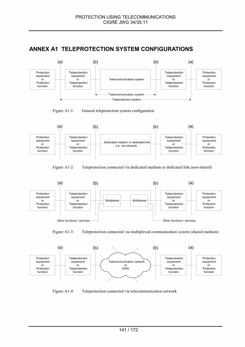
PROTECTION USING TELECOMMUNICATIONSCIGRE JWG 34/35.11
141 / 172
ANNEX A1 TELEPROTECTION SYSTEM CONFIGURATIONS
Protectionequipment
orProtectionfunction
Teleprotectionequipment
orTeleprotection
function
Telecommunication system
Teleprotectionequipment
orTeleprotection
function
Protectionequipment
orProtectionfunction
Telecommunication system
Teleprotection system
(a) (b) (b) (a)
Figure A1-1: General teleprotection system configuration
Protectionequipment
orProtectionfunction
Teleprotectionequipment
orTeleprotection
function
Dedicated medium or dedicated link(i.e. non-shared)
Teleprotectionequipment
orTeleprotection
function
Protectionequipment
orProtectionfunction
(a) (b) (b) (a)
Figure A1-2: Teleprotection connected via dedicated medium or dedicated link (non-shared)
Protectionequipment
orProtectionfunction
Teleprotectionequipment
orTeleprotection
function
Teleprotectionequipment
orTeleprotection
function
Protectionequipment
orProtectionfunction
(a) (b) (b) (a)
Multiplexer Multiplexer
Other functions / servicesOther functions / services
Figure A1-3: Teleprotection connected via multiplexed communication system (shared medium)
Protectionequipment
orProtectionfunction
Teleprotectionequipment
orTeleprotection
function
Teleprotectionequipment
orTeleprotection
function
Protectionequipment
orProtectionfunction
(a) (b) (b) (a)
Telecommunication networkor
WAN
Figure A1-4: Teleprotection connected via telecommunication network

PROTECTION USING TELECOMMUNICATIONSCIGRE JWG 34/35.11
142 / 172
Legend to Figures A1-1 to A1-4:
Protection equipment;Protection function:
Performs the protection function, excluding communication.Synonym for protection relay.
Teleprotection equipment;Teleprotection function:
Converts the information from the protection equipment (relay) into a signal suitable forreliable transmission over a telecommunication link /system/network. Includes all functionsthat are necessary to obtain the desired dependability, security, and data integrity.Performs intermediate function between protection and telecommunication. May alsomultiplex signals from several protection equipments/functions, status indications etc. ontoa single telecommunication channel.
Typical layouts:• Separate equipment for command-based state comparison protection schemes.
Interfaces (a) and (b) are accessible.• May be integrated into the protection equipment, particularly for analog comparison
protection schemes. Interface (b) is accessible. Interface (a) is equipment internal andnormally not accessible.
• May be integrated into telecom terminal equipment. Interface (a) is accessible.Interface (b) is equipment internal and normally not accessible.
Telecommunication system;Telecommunication link:
System composed of telecommunication equipment and the associated physical link /medium required to transmit information signals across a distance
Dedicated medium;Dedicated link:
A medium / link / circuit / channel that carries only the teleprotection service.
Multiplexer: A device which combines several signals or services onto a common medium fortransmission
Telecommunication network: A set of communication and switching devices that work in a collaborating way to provide atelecommunication service between access points distributed over a wide area

PROTECTION USING TELECOMMUNICATIONSCIGRE JWG 34/35.11
143 / 172
Figure A1-5: Typical operating times for protection systems incorporating teleprotection
(a)
Protectionequipment
Tele-protectiontransmitfunction
Telecommuni-cation system(-circuit / -link /-network)1)
Teleprotection receive function Protectionequipment
Circuit breaker
Faultrecognitiontime
10 - 30ms
Time forinitiatingtransmitaction
1 - 5ms
0 - 5
ms
Propa-gationtime 2)
Selectionand decisiontime, incl.O/P circuits
Additionaldelay due todisturbance
Relaydecisiontime
Operatingtimeincludingarcing time
1…10…40ms3) 0 - 20ms 0…10…30ms
4) 30 - 80ms
(b) (b)
(a)
TA2 - 70 ms
Teleprotection operating time(Overall operating time for a teleprotection system)
TC42 - 210 ms
Fault clearing time for a protection system
To2 - 45ms
Nominal transmission time(propagation time not included)
Tac2 - 65 ms
Maximum actual transmission time under disturbed channel conditions for a defineddependability and signal to noise ratio or BER.
(propagation time not included)
Fault inception Fault clearing
Notes:
1) Including the physical medium (cable, fibre) and the telecommunication intermediate- and terminal equipment2) 0 ms applies when interface (b) is connected back to back. The propagation delay depends on the route length and on the number and type
of intermediate and terminal equipment involved.5 ms may be difficult to achieve for networks. However, network latency will normally be offset by short times in the teleprotection receivefunction (typ. 2 … 10 ms) for digital systems operating at 64 kbit/s or higher, such that the requirement for the overall operating time can bemet. See note 3)
3) Typical values for analog (narrowband) teleprotection systems are in the range 10 to 30 msTypical values for digital (wideband) teleprotection systems operating at 64kbit/s or higher are in the range 2 to 10 ms
4) 0 ms can apply to intertripping (direct tripping equipment)2 to 10 ms are typical for state comparison protection relays (time for phase selection and O/P circuits operation)10 to 30 ms are typical for unit protection relays (time for signal comparison and O/P circuits operation)
TB12 - 130 ms
Protection operating time
Tpac12 - 125 ms
Maximum actual protection operating time timeunder disturbed channel conditions for a defineddependability and signal to noise ratio or BER.
(propagation time not included)
Propagationtime

ANN
EX A
2 TE
LEC
OM
MU
NIC
ATIO
N S
YSTE
MS
CH
ARAC
TER
ISTI
CS
Sum
mar
y of
tran
smis
sion
cha
ract
eris
tics
of v
ario
us m
edia
and
tele
com
mun
icat
ion
syst
ems.
All
valu
es a
re a
ppro
xim
ate.
Prop
agat
ion
time
(from
inte
rface
s (b
) to
(b) i
n AN
NEX
A1)
Prop
agat
ion
time
varia
tion
Prop
agat
ion
time
sym
met
ry(D
iffer
entia
l del
ay)
Add
/ Dro
p tim
eR
outin
g re
cove
rytim
e / N
etw
ork
rest
orat
ion
time
Cha
nnel
cro
ssov
erpr
obab
ility
Bit E
rror
Rat
e(ty
pica
l)
Band
wid
th o
rC
apac
ity
Pilo
t Wire
sSi
gnal
pro
paga
tion
time
5-10
µs/k
m<<
1m
s<
1ms
if th
e sa
me
rout
eN
ot a
pplic
able
(Pt-P
t lin
ks)
Not
app
licab
lelo
w(h
uman
erro
r)N
otap
plic
able
few
kH
z;<<
64
kbit/
sPo
wer
Lin
e C
arrie
r lin
ks(H
igh
Volta
ge L
ines
)Si
gnal
pro
paga
tion
time
on H
V lin
e 3.
3µs/
km(+
~1.
5ms
for e
ach
PLC
term
inal
equ
ipm
ent)
<< 1
ms
< 1m
sN
ot a
pplic
able
(Pt-P
t lin
ks)
Not
app
licab
lelo
w(h
uman
erro
r)<
10-3
4 …
8kH
z;<
64kb
it/s1
Mic
row
ave
Link
s.Si
gnal
pro
paga
tion
time
in a
ir 3.
3µs/
km(+
~1…
2ms
for e
ach
term
inal
equ
ipm
ent)
<< 1
ms
< 1m
sif
the
sam
e ro
ute
Not
app
licab
le(P
t-Pt l
inks
)N
ot a
pplic
able
low
(hum
an e
rror)
< 10
-3>
64kb
it/s
Fibr
e O
ptic
Cab
les
Sign
al p
ropa
gatio
n tim
e in
fibr
e ca
ble
~5µs
/km
<< 1
ms
< 1m
sif
the
sam
e ro
ute
Not
app
licab
leN
ot a
pplic
able
low
(hum
an e
rror)
< 10
-6>
64kb
it/s
GEO
Sat
ellit
esSi
gnal
roun
d tri
p tim
e 25
0-28
0ms
(up
+ do
wn)
No
data
ava
ilabl
eN
o da
ta a
vaila
ble
Not
app
licab
leN
o da
ta a
vaila
ble
No
data
ava
ilabl
e<
10-3
> 64
kbit/
s
MEO
Sat
ellit
esSi
gnal
roun
d tri
p tim
e ~1
00m
s(u
p +
dow
n)N
o da
ta a
vaila
ble
No
data
ava
ilabl
eN
ot a
pplic
able
No
data
ava
ilabl
eN
o da
ta a
vaila
ble
< 10
-3>
64kb
it/s
LEO
Sat
ellit
esSi
gnal
roun
d tri
p tim
e 10
…30
ms
(up
+ do
wn)
>> 1
ms
>> 1
ms
Not
app
licab
leN
o da
ta a
vaila
ble
No
data
ava
ilabl
e<
10-3
> 64
kbit/
s
PCM
cab
le li
nks
Sign
al p
ropa
gatio
n tim
e in
cab
le ~
5µs/
km +
max
. 0.6
ms
per 6
4kbi
t/s to
2M
bit/s
Mul
tiple
xer
< 1
ms
< 0.
1ms
Not
app
licab
leN
ot a
pplic
able
exis
ts(S
ync.
failu
re)
< 10
-6>
64kb
it/s
PDH
net
wor
ks
Sign
al p
ropa
gatio
n tim
e in
cab
le 5
µs/k
m +
max
. 0.6
ms
per 6
4 kb
it/s
to 2
Mbi
t/s M
ux +
15µ
s pe
r 2/8
Mbi
t/s M
ux +
1µ
s pe
r rep
eate
r
< 1
ms
< 1m
s~0
.6m
s~1
5min
exis
ts(S
ync.
failu
re)
< 10
-6>
64kb
it/s
SDH
net
wor
ks
Sign
al p
ropa
gatio
n tim
e in
cab
le ~
5µs/
km +
35µ
s fo
r 2M
bit/s
por
t to
STM
1 +
40µ
s ST
M1
aggr
egat
e +
110
µs S
TM1
to 2
Mbi
t/s p
ort
< 3
ms
typi
cal
< 1m
s w
ithbi
dire
ctio
nal
prot
ectio
n
< 12
0µs
per
ADM
or
repe
ater
~ 1m
s fo
r sin
gle
link
failu
re;
depe
ndin
g on
syst
em v
endo
r
exis
ts(S
ync.
failu
re)
< 10
-6>
64kb
it/s
ATM
net
wor
ks
Sign
al p
ropa
gatio
n tim
e in
cab
le ~
5µs/
km +
1 m
s pr
oces
sing
tim
e AT
M E
dge
Mux
+ 6
ms
pack
etiz
atio
n de
lay
for 6
4kbi
t dat
a +
0.5
ms
for e
ach
ATM
cor
e sw
itch
Not
e: N
orm
ally
, the
QoS
par
amet
er fo
r Max
imum
Cel
l Tra
nsfe
r Del
ay (M
axC
TD) w
ill be
def
ined
.E.
g., I
TU-T
I.35
6 su
gges
ts a
n up
per b
ound
on
the
CTD
of 4
00m
s fo
r an
inte
rnat
iona
l ATM
conn
ectio
n.
< 3m
s ce
ll de
lay
varia
tion
(CD
V) fo
rQ
oS c
lass
1 (IT
U-T
I.356
)
No
data
ava
ilabl
e(S
imila
r to
SDH
)
sam
e as
SD
H if
SDH
is tr
ansp
ort
laye
r
Cel
l mis
inse
rtion
ratio
(CM
R) <
1/d
ay(IT
U-T
I.35
6)<
10-6
> 64
kbit/
s
IP n
etw
orks
Non
-det
erm
inis
tic;
No
guar
ante
eN
o gu
aran
tee
Crit
ical
;N
o gu
aran
tee
Not
app
licab
leN
ot a
pplic
able
exis
ts(R
outin
g er
ror)
< 10
-5>
64kb
it/s
on d
eman
d
Ethe
rnet
10M
B LA
N
5…
. 15m
s sh
ared
hub
/ 1…
2m
s sw
itche
d hu
b +
6 …
.12m
s W
AN t
ime
Few
ms;
No
guar
ante
eN
o da
ta a
vaila
ble
Not
app
licab
leN
ot a
pplic
able
exis
ts(a
ddre
ssin
g er
ror)
< 10
-5>
64kb
it/s
Ethe
rnet
100
MB
LAN
1
…..
3ms
shar
ed h
ub /
< 1m
s sw
itche
d hu
b +
6 …
12m
s W
AN ti
me
Few
ms;
No
guar
ante
eN
o da
ta a
vaila
ble
Not
app
licab
leN
ot a
pplic
able
exis
ts(a
ddre
ssin
g er
ror)
< 10
-5>
64kb
it/s
1 For
voi
ce a
nd d
ata
only
. For
pro
tect
ion
sign
al tr
ansm
issi
on, t
he c
apac
ity is
suf
ficie
nt fo
r bin
ary
prot
ectio
n co
mm
ands
(sta
te c
ompa
rison
sch
emes
) or f
or n
on-s
egre
gate
d ph
ase
com
paris
on a
pplic
atio
ns(u
nit s
chem
es).


PROTECTION USING TELECOMMUNICATIONSCIGRE JWG 34/35.11
146 / 172
ANNEX A3 QUALITY OF SERVICE
A3.1 INTRODUCTION TO QOSQuality of Service becomes a hot topic for power network protection when thetelecommunication service is rented from a service provider rather than using dedicated linksthat are under the control of the service user. Transmission media and circuits are typicallyunknown to the service user in this case, and traditional planning methods may no longer apply.
Quality of Service is something that is often talked about as an important user requirement, butin the past little has been done in the standards area to give users any real influence over theQoS they may be able to obtain for the services they require. Typically, service characteristicsare fixed when systems are built or when communications services are subscribed to, afterwhich there is not much that users can do. OSI network and transport layer protocols allowlimited signaling of QoS requirements, but in practice, they offer little more than the ability tochoose throughput classes when X.25 is used.
However, this situation is changing. Real-time applications can differ enormously in theirrequirements for throughput and transit delay. Power network protection has extremely stringentrequirements for delivery within known time-windows, and will often need to use the samecommunication network as other traffic. Therefore, the demand is growing for power utility usersto be able to state or negotiate the QoS they need.
Much of the work on the dynamic treatment of QoS is still at the research stage. QoSmechanisms are being developed for time-critical communications, the Internet, multi-mediacommunications and so on. ITU-T and ISO/IEC are attempting to help in all this by developingsome common concepts and terminology (so that not everything is called a QoS parameter),and by providing a central place where QoS methods and mechanisms can be published.
In the following paragraphs, a general introduction into the concept of QoS is given, followed bya more detailed discussion regarding its application for ATM, where the concept of QoS hasbeen consistently adopted from the beginning.
QoS ParametersIn the common case, everything related to the desired quality of the traffic can be referred to asQuality of Service parameters. One may distinguish between user-level QoS, application-levelQoS, system level QoS and at even lower levels. Parameters considered here relate to thenetwork.
Services may be broadly categorized in a qualitative manner into the following service classesor service categories:
- DeterministicTypical use is for "hard" real-time applications
- StatisticalTypical use is for "soft" real-time applications
- Best effortEverything else, no guarantees are made
This crude approximation will probably not be sufficient in many cases. Thus, the followingquantitative QoS parameters may be specified:

PROTECTION USING TELECOMMUNICATIONSCIGRE JWG 34/35.11
147 / 172
- Throughput can be based both on average data rate and/or peak data rate. The ratio ofpeak rate and average rate of data streams is known as burstiness.
- Reliability relates to a certain probability of data loss which can be tolerated- Delay can be specified based on an absolute or probabilistic bound.- Delay variation or Jitter is the (short-term) variation in delay a message experiences.
Parameters are static if they are valid for the entire duration of the connection. If they can bechanged while a transmission is in progress, they are said to be dynamic.
A3.2 QOS DEFINITION IN ATM NETWORKSAs the concept of QoS has been thoroughly adopted for the specification of ATM layer services,the ATM QoS concept is discussed in some detail below and follows [26].
ATM service classesThe two main bodies that establish ATM specifications are the ATM-Forum and the ITU-T. Aunified approach to the definition of ATM services in the ATM Forum and in ITU-T is presentedin the Table below. The ATM-Forum uses Service Categories instead of ATM TranferCapabilities and QoS classes as defined by the ITU-T. Since different names are adopted todefine concepts that are very similar in purpose, the differences are more apparent than real.The close relationships that have been established between the two bodies give a furtherchance to harmonize their documents in the course of their parallel development.
An ATM Service Category (ATM Forum name) or ATM Transfer Capability (ITU-T name) isintended to represent a class of ATM connections that have homogeneous characteristics interms of traffic pattern, QoS requirements and possible use of control mechanisms, making itsuitable for a given type of network resource allocation. The ATM-Forum has split the ServiceCategories into real-time traffic (CBR and rt-VBR) and non-real-time traffic (nrt-VBR, ABR andUBR). In the ITU-T, real-time and non-real-time are included in the QoS classes rather than inthe ATM Transfer Capabilities. The ATM-Forum on the other hand permits the use of the ITU-TQoS classes, thus the differences are more apparent than real.
A first classification of these services/capabilities may be seen from a network resourceallocation viewpoint. We can identify:
- A category based on a constant (maximum) bandwidth allocation. This is calledConstant Bit Rate (CBR) in the ATM Forum and Deterministic Bit Rate (DBR) in ITU-T.
- A category based on a statistical (average) bandwidth allocation. This corresponds tothe ATM Forum Variable Bit Rate (VBR) and ITU-T Statistical Bit Rate (SBR). The ATMForum further divides VBR into real-time (rt-VBR) and non-real-time (nrt-VBR),depending on the QoS requirements.
- A category based on "elastic" bandwidth allocation, where the amount of reservedresources varies with time, depending on network availability. This is the Available BitRate (ABR). The same name is used both in the ATM Forum and in ITU-T.
- A category considered only in the ATM Forum is the Unspecified Bit Rate (UBR). Noexplicit resource allocation is performed; neither bandwidth nor QoS objectives arespecified.
In the rest of this document, the service categories are addressed based on the ATM Forum"Traffic Management Specification" only.

PROTECTION USING TELECOMMUNICATIONSCIGRE JWG 34/35.11
148 / 172
Correlation of ATM Forum and ITU-T ATM services:
ATM Forum TM 4.0:
ATM SERVICECATEGORY
ITU-T I.371:
ATM TRANSFERCAPABILITY
Traffic characteristics,Purpose Application examples
Constant Bit Rate(CBR)
Deterministic Bit Rate(DBR)
- Real-time / time-delaysensitive data with QoSguarantees
- Low cell delay variation- Circuit emulation
- Videoconferencing- Telephony- Audio/Video Distribution- Teleprotection
Real-Time Variable Bit Rate(rt-VBR) (for further study)
- Bursty real-time data- Efficient use of network
resources for delaysensitive data
- Statistical multiplexing
- Voice communicationwith bandwidthcompression and silencesuppression
- Interactive compressedvideo
- LAN interconnection- SCADA / EMS- Future teleprotection?
Non-Real-Time Variable BitRate(nrt-VBR)
Statistical Bit Rate(SBR)
- Bursty non-real-time data- Efficient use of network
resources for delayvariation insensitive data
- Statistical multiplexing
- Response-time criticaltransaction processingapplications (e.g.,banking transactions)
- Multimedia E-mail- No teleprotection
Available Bit Rate(ABR)
Available Bit Rate(ABR)
- Dynamic bandwidth- Flow control with
feedback- Network resource
exploitation
- LAN interconnection- LAN emulation- TCP/IP- E-Mail- File transfer- No teleprotection
Unspecified Bit Rate(UBR) (no equivalent)
- Best effort delivery, noguarantees
- Applications with vaguethroughput and delayrequirements
- Low cost
- E-Mail- File transfer- Messaging- TCP/IP- No teleprotection
Traffic ParametersA source traffic parameter describes an inherent characteristic of a source. The followingparameters are considered for the purpose of defining the Service Categories :
- Peak Cell Rate (PCR)- Sustainable Cell Rate (SCR)- Maximum Burst Size (MBS) and Burst Tolerance (BT)- Minimum Cell Rate (MCR)- Cell Delay Variation Tolerance (CDVT)- QoS Parameters
The traffic contract defines how the network should react when parameters that characterize thetraffic are exceeded. A traffic contract may be established either when the network user firstsubscribes to a network service, or dynamically via user interface signaling or networkmanagement negotiation.
QoS ParametersThe QoS parameters selected to correspond to a network performance objective may benegotiated between the end-systems and the network, e.g., via signalling procedures, or can betaken as default. One or more values of the QoS parameters may be offered on a per

PROTECTION USING TELECOMMUNICATIONSCIGRE JWG 34/35.11
149 / 172
connection basis:- Peak-to-peak Cell Delay Variation (CDV)- Maximum Cell Transfer Delay (maxCTD)- Cell Loss Ratio (CLR)
A number of additional QoS parameters have been identified, but their negotiation is notforeseen but are assigned at call set-up, e.g.:
- Cell Error Ratio (CER)- Severely Errored Cell Block Ratio (SECBR)- Cell Misinsertion Rate (CMR).
A3.2.1 ATM Service Categories
Constant Bit Rate (CBR)The CBR service category is used by connections that request a fixed (static) amount ofbandwidth, characterized by a Peak Cell Rate (PCR) value that is continuously available duringthe connection lifetime. The source may emit cells at or below the PCR at any time, and for anyduration.Thus, the only traffic parameter specified for the CBR service category is the Peak Cell Rate(PCR).The CBR service category is intended for real-time applications, i.e., those requiring tightlyconstrained Cell Transfer Delay (CTD) and Cell Delay Variation (CDV). It would be appropriatefor protection signal transmission, provided that the signal propagation time requirements (seeANNEX A1) that are influenced by the CTD and CDV parameters can be met.
The basic commitment made by the network is that once the connection is established, thenegotiated QoS is assured to all cells conforming to the relevant conformance tests. It is the endstation's responsibility to send only traffic that is compliant with the contract (PCR). The networkchecks the traffic against the contract, and noncompliant cells are discarded.
Real-Time Variable Bit Rate (rt-VBR)Like CBR, VBR is a reserved bandwidth service. The real-time VBR service category isintended for time-sensitive applications, (i.e., those requiring tightly constrained delay and delayvariation such as voice and video). Sources are expected to transmit at a rate which varies withtime. Equivalently, the source can be described as "bursty".Traffic parameters are Peak Cell Rate (PCR), Sustainable Cell Rate (SCR) and Maximum BurstSize (MBS).Cells which are delayed beyond the value specified by CTD are assumed to be of significantlyless value to the application. Real-time VBR service may support statistical multiplexing of real-time sources.
Rt-VBR may be a candidate to be studied for future teleprotection implementations, asprotection systems typically need little communication capacity during the guard state andrequest significant communication capacity in the operate state.
Non-Real-Time Variable Bit Rate (nrt-VBR)The non-real time VBR service category is intended for applications which have bursty trafficcharacteristics and do not have tight constraints on delay and delay variation.As for rt-VBR, traffic parameters are PCR, SCR and MBS.For those cells which are transferred within the traffic contract, the application expects a lowCell Loss Ratio (CLR). For all cells, it expects a bound on the Cell Transfer Delay (CTD). Non-

PROTECTION USING TELECOMMUNICATIONSCIGRE JWG 34/35.11
150 / 172
real time VBR service may support statistical multiplexing of connections.
Since the transmission of protection signals is extremely time sensitive, non-real-time VBR isnot applicable for teleprotection.
Available Bit Rate (ABR)The Available Bit Rate (ABR) is a service category intended for sources having the ability toreduce or increase their information rate if the network requires them to do so.ABR service can be seen as a mix of reserved and non-reserved bandwidth service.Periodically, a connection polls the network and, based upon the feedback it receives, adjustsits transmission rate. Polling is done by Resource Management (RM) cells sent by the sourceand looped back at the destination so that the network elements and the destination can providefeedback information.It is recognized that there are many applications having vague requirements for throughput.They can be expressed as ranges of acceptable values, e.g., a maximum and a minimum,rather than as an average value (that is typical for the VBR category).Traffic parameters, which the end system may specify, are therefore a maximum requiredbandwidth and a minimum usable bandwidth. These are designated as the Peak Cell Rate(PCR) and the Minimum Cell Rate (MCR), respectively. The MCR may be specified as zero.
Although no specific QoS parameter is negotiated with the ABR, it is expected that an end-system that adapts its traffic in accordance with the feedback will experience a low Cell LossRatio (CLR) and obtain a fair share of the available bandwidth according to a network specificallocation policy. Cell Delay Variation (CDV) is not controlled in this service, although admittedcells are not delayed unnecessarily.
Since ABR service is not (as specified at present) intended to support real-time applications andas no specific QoS parameters are negotiated, the ABR service category is not applicable toprotection signal transmission.
Unspecified Bit Rate (UBR)The Unspecified Bit Rate (UBR) service category is a "best effort" service intended for non-critical applications, which do not require tightly constrained delay and delay variation, nor aspecified quality of service. UBR sources are expected to transmit non-continuous bursts ofcells. UBR service supports a high degree of statistical multiplexing among sources.
As UBR service does not specify traffic related service guarantees, it is not applicable forprotection signal transmission.
The Table below summarizes Service Category Attributes and QoS Guarantees.

PROTECTION USING TELECOMMUNICATIONSCIGRE JWG 34/35.11
151 / 172
QoS Parameters (Guarantees)ATM ServiceCategory
�
TrafficParameters
� Min. Cell Loss(CLR)
Delay andDelay Variance(maxCTD, CDV)
Bandwidth
Use ofFeedbackControl
CBR PCR, CDVT YES YES YES NO
rt-VBR PCR, SCR, MBS,CDVT YES YES YES NO
nrt-VBR PRC, SCR, MBS,CDVT YES NO YES NO
ABRPCR, MCR, CDVT(+ traffic behaviorparameters)
YES NO YES YES
UBR PCR, CDVT NO NO NO NO
A3.2.2 ATM over SDH/SONETATM may use various technologies as its transport vehicle (physical layer). Frequently,SDH/SONET transport systems will be used. Errors introduced by the transport system as wellas other impairments will have a negative impact on the QoS. The Table below shows somesources of degradation for the ATM QoS parameters.
QoS Parameters
CERCell Error
Ratio
CLRCell Loss
Ratio
CMRCell
MisinsertionRatio
maxCTDMaximum
Cell TransferDelay
CDVCell DelayVariation
PropagationTime X
PropagationTimeVariation
X X
Link
/ ne
twor
k /
med
ium
para
met
ers
Bit Errors /Media Errors X X X
SwitchArchitecture X X X
BufferCapacity X X X
ATM
spe
cific
Traffic Load /ResourceAllocation
X(except CBR)
X(except CBR)
X(except CBR)
X(except CBR)
Number ofNodes / Hops X X X X X
Gen
eral
netw
ork
desi
gn Network /HardwareFailures
X
The following Table shows the expected impact of QoS parameters onto generalcommunication performance parameters at interface (b) in the Figures in ANNEX A1, and theirpossible adverse impact onto the (tele)protection function. It is noted that the table isspeculative as little experience yet exists with protection signal transmission over ATM.

PROTECTION USING TELECOMMUNICATIONSCIGRE JWG 34/35.11
152 / 172
Communication performanceparameters (Tele-)Protection parameters
BERBit Error Rate Jitter Dependability Security Transmission
TimeCERCell Error Ratio X X X X
CLRCell Loss Ratio X X X
CMRCellMisinsertionRatio
X X X X
maxCTDMaximum CellTransfer Delay
(X) X
ATM
QoS
par
amet
ers
CDVCell DelayVariation
X (X) (X)
A3.2.3 Applications SummaryThe Table below is an attempt to sum up the indications outlined in this section as related totypical power utility applications. It is not intended to create a restrictive correspondencebetween the identified application areas and ATM-layer services, and should therefore not betaken restrictively.
Application areas for ATM service categories:
APPLICATION AREA�
CBR rt-VBR nrt-VBR ABR UBR
Critical Data, not delaysensitive fair fair optimum fair not suitable
Critical Data, delaysensitive good good not suitable not suitable not suitable
Circuit Emulation optimum good not suitable not suitable not suitable
LAN InterconnectLAN Emulation fair fair good optimum good
State ComparisonProtection SignalTransmission
good fair…optimum ? not suitable not suitable not suitable
Analog ComparisonProtection SignalTransmission
good fair…optimum ? not suitable not suitable not suitable
The ratings (optimum - good - fair - not suitable) refer to the efficiency/cost advantages the useof ATM may have for the stated application areas. The ratings given for protection signaltransmission are speculative and apply subject to the condition that native ATM interfaces areavailable and that the requirements for the end-to-end signal propagation time can be fulfilled(see Figure A1-5).
A3.3 QOS DEFINITION IN IP NETWORKSAlthough IP networks have been traditionally considered as best-effort networks, the new QoSarchitecture has widened their applications. The Internet Engineering Task Force IETF hasdefined two models for providing QoS: the Integrated Services (Int-serv) and the DifferentiatedServices (Diff-serv).
The Integrated Services model is based on the resource reservation paradigm. Before data

PROTECTION USING TELECOMMUNICATIONSCIGRE JWG 34/35.11
153 / 172
are transmitted, the applications must set-up a path and reserve the resources. This workingprinciple resembles the one used in circuit switched networks therefore being adequate for non-elastic applications such as voice telephony, or Protection communication in the future. Thecomplete implementation of this architecture requires QoS aware applications or the addition ofGateways between the legacy applications and the Integrated Services core since the networkhas to be informed about the profile of the traffic offered and the QoS requirements of the user.
Differentiated Services is based on the definition of different classes of services. The packetsare marketed differently depending on the service class their application/flow belongs to.Therefore, Differentiated Services is essentially an evolution of the static-priority scheme.Whereas Int-serv architecture guarantee and End-to-End QoS, that is to say, application-to-application, the Diff-serv architecture guarantees the QoS only in its own domain.
Differentiated Services is an evolving architecture and in fact, still an immature technologyunder discussion by different working groups of the IETF.
The provision of QoS for the Teleprotection application is a must, since both the bandwidth andthe delay of the virtual channel established throughout the network to support the protectionrelay communication has to be guaranteed in a deterministic way.
Existing protection relays do not include IP Ethernet interface; therefore, we have to focus onthe new and evolving technologies. In this field, the new Utility Communication ArchitectureUCA is the most relevant example. The UCA architecture is based on the use of standardprotocol stacks. Two tracks with different profiles have been defined including both the ISO andthe TCP/IP approaches.
Data interchange with devices in real-time networking environments is accomplished by addingthe following specific components:
- Generic Object Models for Substation and Feeder Equipment, (GOMSFE) which definesa set of object models for use across a broad range of typical utility devices;
- Generic Object Oriented Substation Event, (GOOSE) which allows a device to broadcaststatus information on the local segment;
- Common Application Service Models, (CASM) which defines a standardized set ofabstract services supporting the UCA object models, as well as the methods of mappingthe services to the Manufacturing Message Services (MMS).
None of these application elements have been designed to specify their QoS requirements tothe network. Therefore, the provision of Teleprotection service will require static QoSrequirements that will have to be introduced in the Network Management Centre.
Three classes of services could be identified in IP QoS networks: Guaranteed Service,Controlled Load and Best-Effort.
The first one is used to support those applications that are non-tolerant to uncontrolled delaysand/or losses. The second is used to support elastic applications, that is to say, applicationsthat can control the traffic flow that they are offering to the network and therefore can toleratesome changes in delay and throughput, whereas that the third one is used by those applicationsthat do not require QoS.
Teleprotection service is associated with the Guaranteed Service class. Nevertheless, special

PROTECTION USING TELECOMMUNICATIONSCIGRE JWG 34/35.11
154 / 172
care has to be taken to verify that the network is providing deterministic guarantees. To achievethis, the network architecture requires a set of components to be provided.
The principle of QoS assurance is based on an interaction between the user and the network.This interaction is expressed by means of a Traffic Contract or agreement that includes thecommitments of both parties.
The total delay has two parts: a fixed delay caused by the transmission delay of the path and aqueuing delay caused by the intermediate nodes. The fixed delay depends only on the chosenpath and is not determined by the QoS mechanism but by the setup mechanism. The queuingdelay is determined and controlled by the QoS mechanism provided by the network. Thequeuing delay is primarily a function of two parameters the token bucket size and the data rate.These two values are under the application control, and therefore, the application can estimatethe delay and if it is larger than required, the bucket size and the rate can be modified toachieve a lower delay.
The end-to-end QoS is based on an assured bandwidth provided by the network that, whenused by a shaped flow, produces a delay bound service with no queuing loss. This servicescheme can only control the maximal queuing delay without providing any kind of control on thejitter since the delay will change from the transmission delay of the path to the transmissiondelay plus the queuing delay.
The traffic profile is specified by means of the Traffic Specification or TSpec whereas that theQoS requirements are specified by means of the Service Request Specification or RSpec. Bothspecifications form the two parts of the Traffic Contract.
TSpec defines the flow’s traffic pattern allowed in terms of the average packet rate, maximumburst rate and size, and the packet size. It has to be considered that these parameters definethe maximum allowed not the actual traffic profile. Excess traffic could be directly discarded ortransmitted as Best-effort depending on the traffic policy of the network.
RSpec specifies the QoS a flow requires. That is to say, the bounded maximum End-to-Enddelay expressed in this case by means of the bandwidth reservation required by the flowdefined by means of TSpec. The network should reserve enough resources to guarantee thatno losses due to network congestion will ever occur. A detailed specification of the QoSparameters including formats and range of values can be found in the RFC 2212 “Specificationfor Guaranteed Quality of Service”. The same document also describes internal networkarchitecture to achieve end-to-end QoS.
TSpec and RSpec are calculated by a QoS reservation algorithm embedded in the application.The algorithm takes into account the actual QoS requirement and the propagation delay of thepath to carry out the calculation of the TSpec and RSpec parameters That once accepted by theadmission control will be delivered to the network elements.
Other QoS aspects such as service availability are not defined in the Traffic Contract. Theyhave to be achieved by means of the proper network design.

PROTECTION USING TELECOMMUNICATIONSCIGRE JWG 34/35.11
155 / 172
Parameter Units RangeBucket depth “b” Bytes/sec 1 to 40 Tbytes/secBucket rate “r” Bytes/sec 1 to 40 Tbytes/secPeak rate “p” Bytes/sec 1 to 40 Tbytes/secMinimum policed unit “m”Datagrams shorter than m areaccounted as length m
Bytes m<M
Maximum datagram size “M” Bytes M<=MTU
Table 8.3-1: TSpec Parameters
Parameter Units Range
Transmission rate “R” Byte/sec 1 to 40 Tbytes/secR>r
Slack term “s”Difference between the desired delayand the delay obtained using “R”
µsec 0 to 232-1µsec
Table 8.3-2: RSpec Parameters
Although IP networks can offer deterministic guarantees to those flows that require it, only themaximum end-to-end delay can be controlled. The difference between the propagation delayand the bounded delay that includes the queuing delay cannot be controlled, thereby obtaininga considerable delay jitter that can impair the global quality of the virtual connection. This jittercould be increased by the imprecision of the queue schedulers in the packet switches. That is tosay, the algorithm that controls the process of packet switching can only offer the calculatedperformance for infinitesimal short packets. The longer the packets the bigger the imprecision inthe delay control. It has to be considered that the packet length of any other flow switched in thesame node will affect the delay jitter of our flow. Due to this, the use of IP networks to supportTeleprotection services should be limited to well-controlled domains in which all the abovementioned factor fall into our control.
ATM technology, which is based on a short and fix packet length called cell, can be envisionedas feasible solution to support the Teleprotection service since it can guarantee and effectivelycontrol both the delay and the delay variation.
The combination of IP technology that offers cost-effective access interfaces and the ATMtechnology that offers network wide reliable delay control might probably be one futureapproach to support the Teleprotection service in the broadband environment.Lit:. [31], [32], [33], [34], [35], [36].
A3.4 IP TO ATM SERVICE MAPPINGThe service offered to the final user of the network, which could be defined by the service classand its QoS parameters, should not be affected by the network implementation. That is to say,services classes, traffic descriptors and QoS parameters of a QoS IP network have to bemaintained even thought ATM backbones or any IP over ATM architecture had been chosen toimplement the network.
In order to achieve this goal, the devices that interconnect the IP and the ATM subnetworkshave to include, among others, the capability of translating every service aspect as well as QoSparameters in order to assure an end-to-end QoS.
Due to the different service definition in both networks the services are mapped according to the

PROTECTION USING TELECOMMUNICATIONSCIGRE JWG 34/35.11
156 / 172
following association:
- Guaranteed Service � CBR or rtVBR- Controlled Load � nrtVBR or ABR (with a minimum cell rate)- Best Effort � UBR or ABR
The details of service mapping as well as the QoS and traffic parameters could be found in theRFC 2381. “Interoperation of Controlled-Load Service and Guaranteed Service with ATM”, [36].
Traffic and QoS parameters are defined in the IP environment in terms of bytes/s whereas thatin ATM are defined in cells/s. The corresponding mathematical transformations that takes intoaccount overhead introduced by the different size of IP and ATM headers can be found in RFC2381, [36]. Since these functions are included in the standards, they are always included in theGateways that interconnect IP and ATM networks.
A3.5 QUALITY OF SERVICE STANDARDS
ITU-T RECOMMENDATION
No. TITLEISO/IEC
EQUIVALENT
E.800 Terms and definitions related to quality of service and network performanceincluding dependability none
X.140 General quality of service parameters for communication via public datanetworks none
X.641 Information technology - Quality of Service - Framework 13236
X.642Information technology - Quality of Service – Guide to methods andmechanisms
(presently at the stage of draft)13243
I.350 General aspects of quality of service and network performance in digitalnetworks, including ISDNs none
I.356 B-ISDN ATM layer cell transfer performance none
I.371 Traffic Control and Congestion Control in B-ISDN none
I.731 Types and general characteristics of ATM equipment(Paragraph 7: Generic performance requirements) none
Q.2723.1 B-ISDN User Part - Support of additional traffic parameters for SustainableCell Rate and Quality of Service none

PROTECTION USING TELECOMMUNICATIONSCIGRE JWG 34/35.11
157 / 172
ANNEX A4 PROTECTION SYSTEM TIME SYNCHRONIZATIONTECHNIQUES
A4.1 TIME SYNCHRONISATION FOR SIMULTANEOUS SAMPLINGTwo principal teleprotection functions for microprocessor-based current differential lineprotection, in which protection relays are comparing data with the same tag of time, is to providethe timing synchronization for the simultaneous sampling of current waveforms at all remoteterminals of the line and the current data transmissions among the terminals. There are twoways to achieve timing synchronization; internal timing synchronization using its ownteleprotection signaling channel and external timing synchronization using external timingsource such as GPS as shown in Figure 8.3-1.
Figure 8.3-1: Two ways of timing synchronization for current differential teleprotection
A4.1.1 Internal timing synchronizationThe internal timing synchronization scheme between two terminals is implemented in thetransmission or teleprotection equipment, and timing synchronization signals are transmitted inthe teleprotection channel to self-adjust the internal clocks of the terminals by sending amessage back and forth between the terminals. There are basically two types of messagetransmissions including timing pulses between master (or reference) and slave (orsynchronizing) terminals: round-trip and mutual (or two-way) transmission methods. However,many variations exist for implementation.
In the round-trip transmission method shown in Figure 8.3-2(a), a reference timing pulse at themaster terminal is transmitted to the slave terminal. The transmitted reference pulse is returnedto the master terminal. The returned reference pulse is delayed by round-trip transmissionthrough the outgoing and incoming transmission lines (δ1 and δ2). Transmission delay ismeasured at the master terminal, and the data is transmitted to the slave node. The slave nodeexecutes delay compensation corresponding to a half of the round-trip delay, (δ1 + δ2)/2 toachieve timing synchronization.

PROTECTION USING TELECOMMUNICATIONSCIGRE JWG 34/35.11
158 / 172
In the mutual or two-way transmission method, both terminals mutually transmit referencepulses. Each terminal measures the time difference between the transmission of its own pulseand the reception of the opposite terminal's pulse; TM at the master terminal and TS at theslave terminal. TM is transmitted to the slave terminal which executes delay compensationcorresponding to a half of the difference between the two delays, (TM - TS)/2. The delaycompensation is initiated upon reception of the master node's pulse by the slave terminal. Asynchronization error of a few microseconds between two PDH-based synchronization deviceswas experimentally obtained in multi- (four or five) repeater microwave.
Figure 8.3-2: Two-types of timing pulse transmission methods
Figure 8.3-3 shows another implementation. A terminal acts as the reference clock for thesystem. A numbered message is sent from the synchronizing terminal at time tA1. It is receivedat time tB1’ at the reference terminal and returned back at time tB2. It is received at thesynchronizing terminal at time tA2’. The times tB1’ and tB2 are sent with the next message to thesynchronizing terminal. The difference ∆t between the clocks in the synchronizing and thereference terminal can now be calculated by the synchronizing terminal as
222'1'21 BBAA tttt
t+
−+
=∆
The clock in the synchronizing terminal can now be adjusted by a fraction of ∆t until ∆t becomeszero. The synchronizing and reference terminal clocks are synchronized and the samples ofcurrent can be compared at the same sampling instant. Since the clocks are crystal controlled,they maintain synchronism for long times of transmission interruptions [16].
Figure 8.3-3: Implementation of round-trip transmission method
Another implementation is shown in Figure 8.3-4. In this case the terminals also use the samedata polling technique as described above for the measurement of the channel delay time.Every terminal calculates the time delay δ with regard to the other ones as

PROTECTION USING TELECOMMUNICATIONSCIGRE JWG 34/35.11
159 / 172
2)()( '121'2
21BBAA tttt −−−
==≡ δδδ
With the measurement of the time delay, the local sampling timing can be adjusted asδ−= 22 AAB tt .
Figure 8.3-4: Another implementation of round-trip transmission method
Although this method can achieve synchronization between the terminals, an asynchronousoperation where the internal clocks of the terminals don’t need to be synchronized can be alsoperformed. The sampling time of the received current vector values from the remote terminalcan be measured as tAB2. Since the current samples have not been taken at the same samplinginstant, a vector transformation in software is required to rotate the remote vector by an anglecorresponding to the time tAB2 - tA2, and then to compare with the local value sampled at tA2.
These procedures assume the same time delay δ in both directions, so in communicationsystems where both directions can be switched via different routes (SDH and ATM networks)the difference in time delay for data transfer in both directions will introduce an error in thedetermination of the differential current [15], [5]. Requirements on differential time delay andsolutions are discussed in chapter 6.
A4.1.2 External timing synchronizationInternal terminal-to-terminal basis synchronization may not be available for wide-areaapplications, because the multiple-link synchronization mechanism is hard to be implemented inconventional telecommunication or teleprotection equipment. External time synchronous signalmay be effective for that purpose. This eliminates the timing synchronization function from thetelecommunication system used for teleprotection signaling channels, which makes thetelecommunication system design much easier.
There are many ways to provide precise timing signals externally. Form the viewpoint oftechnological maturity and the ease of availability, the satellite-based Global Positioning System(GPS) is a solution [17], [18]. Other satellites such as the Russian GLONASS (GlobalNavigation Satellite System) are also candidates for the wide-area time dissemination.
Synchronization with GPS satellite signals is the preferred technique at the present time. GlobalPositioning System using on-board atomic clocks (cesium or rubidium) consists of 24 satellitesin 12-hour orbits at an altitude of 20,183 km. There are six orbits used with 4 satellites in eachorbit. Using the transmissions from these satellites, positions of objects can be determined withan accuracy of 10 meters in three dimensions, and in the common-view time transmissionprovided by these satellites, 1-pulse-per-second (1-pps) signals at any location in the world withan accuracy of about 1 µs (basic time synchronization accuracy is ±20 ns) are available when

PROTECTION USING TELECOMMUNICATIONSCIGRE JWG 34/35.11
160 / 172
decoded by appropriate receiver clocks. Synchronous phasor measurement technique usingGPS has been developed to measure power system phasors, transmit the data with time-tags,and then record or analyze them in real time [19]. The technique can be used for teleprotectionsignaling and wide-area adaptive protections. Prudent considerations should be taken withregard to unavailability and/or precision degradation due to intentional or unintentional radiointerference, satellite and/or receiver failures and so on. Recently, however, highly accurate butlow-cost timing sources which is usually synchronized with the GPS clock and maintains amicrosecond-order accuracy for several days even when the GPS signal is lost are beingdeveloped.
A variety of alternatives exist for time synchronization using a terrestrial signal from a centrallocation. AM radio broadcasts are least expensive, but their accuracy is limited to a fewmilliseconds. An access to reference time server using UNIX-based NTP (network timeprotocol) via TCP/IP networks or Internet is less accurate. Utilities can use their own privatetelecommunication channels such as microwave or fiber-optic circuits where the solution mayapproach 1 µs, and custom or dedicated fiber-optic links may achieve better accuracy.
In terms of future use by utilities of broadband digital communications, SDH networks, which arepresently master-slave frequency synchronous networks, appear promising for a terrestrial timesynchronous system. Terrestrial SDH-based time synchronous system of which accuracy iscomparable with GPS is under study in several organizations [20], [21]. Current SDH networksare equipped with clock supplies to synchronize its operation clock frequency all over thenetwork, making it easy to handle multiplexing and demultiplexing of digital signals. In order totime-synchronize frequency-synchronized networks of this type, externally additive timesynchronizing equipment which transmits time signals to adjacent nodes, measures round-tripor two-way delays between the nodes, and compensates the two-way differential delay, wasproposed as shown in Figure 8.3-5, [21]. To transmit a time signal, especially reference timingpulse in SDH networks, undefined bytes in the SDH frame overhead are used. In the systemauxiliary time synchronizing equipment (TSE) is attached to existing SDH transmissionequipment and clock supply equipment (CSE). In these systems frequency synchronization isconducted by CSEs which usually have a digital processing phase locked loop, and phase ortime synchronization is carried out by TSE. Experimental results indicated that an accuracy ofabout 1 µs can be achieved.
SDH: SDH Transmission Equipment (existing)CSE: Clock Supply Equipment (existing)TSE: Time Synchronous EquipmentM: Master, S: Slave
M
S S
S S S
GPS Time Transfer
GPS satellites
Timesignal
Power Control and Protection System
GPSreceivers
Slavestations
Master station
Terrestrial Time Transferusing digital (SDH) networks
Slavestations
Timesignal
Timesignal
Clock Data
SDH
SDH
CSE-M
TSE-M
CSE-S
TSE-S
Figure 8.3-5: GPS and an SDH-based master-slave time transfer network

PROTECTION USING TELECOMMUNICATIONSCIGRE JWG 34/35.11
161 / 172
LIST OF FIGURESFIGURE 2.1-1: SINGLE-LINE DIAGRAM OF A TYPICAL POWER STATION........................................................................9FIGURE 2.1-2: SINGLE LINE DIAGRAM OF A TYPICAL TRANSFORMER STATION ..........................................................10FIGURE 2.1-3: THE SCANDINAVIAN POWER GRID.....................................................................................................11FIGURE 2.2-1: POWER LINE WITH EXAMPLES OF FAULT TYPES AND FAULT POSITIONS ..............................................12FIGURE 2.4-1: TYPICAL POWER SYSTEM AND ITS ZONES OF PROTECTION..................................................................16FIGURE 2.4-2: OVERLAPPING PROTECTION ZONES ESTABLISHED BY CURRENT TRANSFORMER LOCATION ................17FIGURE 2.4-3: FAULT CLEARING SYSTEM..................................................................................................................18FIGURE 2.5-1: FUNDAMENTAL TERMS ON PROTECTION AND TELEPROTECTION (FROM IEC60834-1) .......................20FIGURE 3.1-1: PRINCIPLE OF DIFFERENTIAL PROTECTION..........................................................................................23FIGURE 3.1-2: DIFFERENTIAL PROTECTION: EXAMPLE OF PERCENTAGE RESTRAINT CHARACTERISTIC .....................23FIGURE 3.1-3: BASIC SCHEME OF A CURRENT BALANCED SYSTEM USING THREE PILOT WIRES ..................................25FIGURE 3.1-4: CENTRALIZED CONFIGURATION .........................................................................................................27FIGURE 3.1-5: DISTRIBUTED CONFIGURATION ..........................................................................................................27FIGURE 3.1-6: PHASE COMPARISON OPERATING PRINCIPLES .....................................................................................29FIGURE 3.1-7: OPERATION OF CHARGE COMPARISON, EXTERNAL FAULT..................................................................31FIGURE 3.1-8: BIAS CHARACTERISTIC OF CHARGE COMPARISON...............................................................................32FIGURE 3.1-9: IDEAL POLAR DIAGRAM CHARACTERISTIC..........................................................................................32FIGURE 3.1-10: INTERTRIPPING UNDERREACH DISTANCE PROTECTION SCHEME LOGIC.............................................35FIGURE 3.1-11: PERMISSIVE UNDERREACH DISTANCE PROTECTION SCHEME LOGIC .................................................36FIGURE 3.1-12: PERMISSIVE OVERREACH DISTANCE PROTECTION SCHEME LOGIC....................................................37FIGURE 3.1-13: ACCELERATED UNDERREACH DISTANCE PROTECTION SCHEME LOGIC.............................................38FIGURE 3.1-14: BLOCKING OVERREACH DISTANCE SCHEME LOGIC...........................................................................40FIGURE 3.1-15: DEBLOCKING OVERREACH DISTANCE PROTECTION SCHEME LOGIC .................................................41FIGURE 3.2-1: TWO BREAKER BUSBAR CONFIGURATION...........................................................................................42FIGURE 3.2-2: 1½ BREAKER BUSBAR CONFIGURATION .............................................................................................44FIGURE 3.2-3: TWO PROTECTION ZONES / ONE BREAKER BUSBAR CONFIGURATION..................................................46FIGURE 3.3-1: GENERATOR PROTECTION ..................................................................................................................47FIGURE 3.3-2: TRANSFORMER PROTECTION ..............................................................................................................48FIGURE 3.3-3: REACTOR PROTECTION.......................................................................................................................48FIGURE 3.4-1: RELATIONSHIP BETWEEN PROTECTED AREA AND OPERATE TIME WITH RESPECT TO PROTECTION
SCHEMES 49FIGURE 3.4-2: DISTANCE PROTECTION PROVIDING REMOTE BACKUP ........................................................................50FIGURE 3.4-3: SPLITTING PROTECTION (BD) USING TELECOMMUNICATIONS FOR MULTI-CIRCUIT AND MULTI-
TERMINAL LINE. RY, CB AND TD DENOTE OPERATING TIMES OF RELAY (30 MS) AND CB (40 ............................50FIGURE 3.4-4: COORDINATION TIME CONTROL USING TELECOMMUNICATIONS. RY, CB AND TD DENOTE OPERATING
TIMES OF RELAY (30 MS) AND CB (40 MS) AND TIME DELAY FOR COORDINATION, RESPECTIVELY. ....................51FIGURE 3.4-5: WIDE-AREA CURRENT DIFFERENTIAL BACK-UP PROTECTION EMPLOYING TELECOMMUNICATIONS....52FIGURE 3.4-6: A SYSTEM-WIDE PROTECTION; PREDICTIVE OUT-OF-STEP PROTECTION .............................................54FIGURE 4.4-1: PRINCIPLE OF WAVELENGTH DIVISION MULTIPLEXING FOR 2 WAVELENGTHS, ................................70FIGURE 4.5-1: NETWORK ARCHITECTURE.................................................................................................................76FIGURE 4.5-2: NETWORK COMPONENTS....................................................................................................................77FIGURE 4.5-3: SEVEN LAYER OSI MODEL .................................................................................................................78FIGURE 4.5-4: REFERENCE MODEL OF THE CIRCUIT EMULATION SERVICE (CES).....................................................81FIGURE 4.5-5: LAN TOPOLOGIES .............................................................................................................................83FIGURE 4.5-6: LAN PROTOCOL LAYERING................................................................................................................84FIGURE 6.1-1: INAPPROPRIATE OVERLAPING OF RELAY COMMUNICATION LINKS IN A DOUBLE REDUNDANT
PROTECTION SYSTEM .........................................................................................................................................111FIGURE 8.1-1: LOCAL AND WIDE AREA NETWORKS FOR PROTECTION .....................................................................131FIGURE 8.1-2: INTEGRATED SUBSTATION APPLICATIONS DEALT IN UCA ARCHITECTURE.......................................132FIGURE 8.1-3: SUBSTATION LANS CONNECTED BY A WAN ...................................................................................134FIGURE 8.2-1: SUBSTATION WITH LAN CONFIGURATION .......................................................................................135FIGURE 8.2-2: HV (SUB)NETWORK WITH WAN......................................................................................................136FIGURE 8.3-1: TWO WAYS OF TIMING SYNCHRONIZATION FOR CURRENT DIFFERENTIAL TELEPROTECTION ............157FIGURE 8.3-2: TWO-TYPES OF TIMING PULSE TRANSMISSION METHODS..................................................................158

PROTECTION USING TELECOMMUNICATIONSCIGRE JWG 34/35.11
162 / 172
FIGURE 8.3-3: IMPLEMENTATION OF ROUND-TRIP TRANSMISSION METHOD ............................................................158FIGURE 8.3-4: ANOTHER IMPLEMENTATION OF ROUND-TRIP TRANSMISSION METHOD............................................159FIGURE 8.3-5: GPS AND AN SDH-BASED MASTER-SLAVE TIME TRANSFER NETWORK ............................................160

PROTECTION USING TELECOMMUNICATIONSCIGRE JWG 34/35.11
163 / 172
LIST OF TABLESTABLE 3.1-1: STATE COMPARISON PROTECTION SCHEMES .....................................................................................34TABLE 4.3-1: ADVANTAGES AND DISADVANTAGES OF PILOT WIRES.......................................................................60TABLE 4.3-2: ADVANTAGES AND DISADVANTAGES OF POWER LINE CARRIER LINKS................................................62TABLE 4.3-3: ADVANTAGES AND DISADVANTAGES OF RADIO LINKS .......................................................................65TABLE 4.3-4: ADVANTAGES AND DISADVANTAGES OF OPTICAL FIBRE LINKS ..........................................................67TABLE 4.3-5: ADVANTAGES AND DISADVANTAGES OF SATELLITE LINKS.................................................................69TABLE 4.4-1: PDH - PLESIOCHRONOUS DIGITAL HIERARCHY LEVELS....................................................................72TABLE 4.4-2: SDH - SYNCHRONOUS DIGITAL HIERARCHY LEVELS ........................................................................73TABLE 5.3-1: SERIAL DATA INTERFACES .................................................................................................................95TABLE 5.3-2: COMMON PHYSICAL LAN INTERFACES..............................................................................................98TABLE 6.1-1: REQUIREMENTS FROM PROTECTION ON TELECOMMUNICATION AND TELEPROTECTION: STATE
COMPARISON SCHEMES. FOR TERMS AND DEFINITIONS REFER TO CHAPTERS 6.1.1.1 AND 6.1.1.2. ...................106TABLE 6.1-2: REQUIREMENTS FROM PROTECTION ON TELECOMMUNICATION AND TELEPROTECTION: ANALOG
COMPARISON SCHEMES. FOR TERMS AND DEFINITIONS REFER TO CHAPTERS 6.1.1.1 AND 6.1.1.2. ...................107TABLE 6.4-1: IEC PUBLICATIONS FOR EMC AND INSTALLATION ..........................................................................118TABLE 7.1-1: PROTECTION SCHEMES VS. MEDIA...................................................................................................120TABLE 7.1-2: PROTECTION SCHEMES VS. MULTIPLEXING TECHNIQUES ................................................................121TABLE 7.1-3: PROTECTION SCHEMES VS. NETWORK TECHNOLOGIES....................................................................122TABLE 7.1-4: CONFIGURATION SUMMARY.............................................................................................................123TABLE 7.2-1: CHECKLIST FOR INTERFACE CO-ORDINATION BETWEEN PROTECTION / TELEPROTECTION /
TELECOMMUNICATION DEVICES ........................................................................................................................127TABLE 8.3-1: TSPEC PARAMETERS........................................................................................................................155TABLE 8.3-2: RSPEC PARAMETERS........................................................................................................................155

PROTECTION USING TELECOMMUNICATIONSCIGRE JWG 34/35.11
164 / 172
BIBLIOGRAPHY[1] CIGRE SC34 WG34-35.05, "Protection systems using telecommunications”, TB 13,
1987.[2] CIGRE SC34 WG34.05, "Application of wide-band communication circuits to protection -
prospects and benefits”, TB 84, 1991.[3] CIGRE SC34 WG34.01, "Reliable Fault Clearance and Back-up Protection", TB 140,
April 1999.[4] T. Nagasawa and et al., "Present Situation and Experiences of Back-up Protection in
Japanese EHV Networks", CIGRE SC34, South Africa, 1997.[5] Y. Serizawa, et al., “Wide-band communication requirements for differential
teleprotection signaling” 600-03, CIGRE Symposium Helsinki 1995.[6] Y. Serizawa, et al., "Wide-Area Current Differential Backup Protection Employing
Broadband Communications and Time Transfer Systems", IEEE PES 1998 WinterMeeting, PE-203-PWRD-0-11-1997, Tampa, 1998.
[7] T. Nagasawa, et al., "Present Status and Experiences in Grouping of ProtectionFunctions in Integrated Systems", 1999 CIGRE SC34 Colloquium, 108, Florence, Italy,October 1999.
[8] J. Kobayashi, et al., "The State of the Art of Multi-circuit and Multi-terminal OverheadTransmission Line Protection Systems Associated with Telecommunication Systems",CIGRE, Paris, 34-203, 1990.
[9] CIGRE SC34 WG34.02, "Adaptive Protections and Control", 1995.[10] Y. Ohura, et al., "A Predictive Out-of-Step Protection System Based on Observation of
the Phase Difference between Substations", IEEE Trans. Power Delivery, Vol. 5, No. 4,1990.
[11] M. Tsukada, et al., "New Stabilizing Protection Systems with an Adaptive ControlApproach", 34-204, CIGRE SC34 Colloquium, Stockholm, 1995.
[12] "Wavelength Division Multiplexing for Electricity Utilities"; TB 131 to be published.[13] CIGRE SC35 WG35.07, "Power System Communications in the High Speed
Environment", TB 107, December 1996.[14] ATM Forum af-saa-0032.000, “Circuit Emulation Service Interoperability Specification”,
September 1995.[15] C.G.A Koreman et al., "Requirements for SDH networks due to protection signalling”
400-02, Cigré Symposium Helsinki 1995.[16] T. Einarsson et al., "Experiences of current differential protections for multi-terminal
power lines using multiplexed data transmission systems” 34-203, Cigré Session 1994.[17] W. Lewandowski and C. Thomas, "GPS Time Transfer", Proc. IEEE, Vol. 79, No. 7,
1991.[18] R. E. Wilson, "Use of Precise Time and Frequency in Power Systems", Proc. IEEE, Vol.
79, No. 7, 1991.[19] IEEE Std 1344-1995, "IEEE Standard for Synchrophasors for Power Systems", IEEE
Power Engineering Society, 1996.[20] M. Kihara and A. Imaoka, "System configuration for standardizing SDH-based time and
frequency transfer", European Frequency and Time Forum, No.418, pp. 465-470, 1996.[21] Y. Serizawa et al., "SDH-Based Time Synchronous System for Power System
Communications", IEEE Trans. Power Delivery, Vol. 13, No.1, Jan. 1998.[22] K. Yanagihashi et al., "Applications of co-ordinated control, protection and operation
support system in EHV substations", CIGRE SC34, Paris, 1996.[23] "Utility Communication Architecture: Substation Integrated Protection, Control and Data
Acquisition: Requirements Specification", RP3599-01, EPRI, 1996.[24] J. T. Tengdin, et al., "LAN Congestion Scenario and Performance Evaluation", IEEE

PROTECTION USING TELECOMMUNICATIONSCIGRE JWG 34/35.11
165 / 172
PES Winter Meeting, New York, 1999.[25] M. Tsukiyama et al., "Reliability of new digital type current differential carrier relaying
system via microwave channel", CIGRE SC34/35 Colloquium, Tokyo, 1983.[26] "ATM Service Categories: The Benefits to the User", The ATM Forum, White Paper
EMAC, 1997.[27] IEC 60834-1, Second edition 1999-10, "Teleprotection equipment of power systems -
Performance and testing. Part 1: Command systems[28] IEC 60834-2, First edition 1993-06, "Performance and testing of teleprotection
equipment of Power Systems - Part 2: Analogue comparison systems[29] IEC 6061850-5, 1st CD February 1999, "Communication Networks and Systems in
Substations - Part 5: Communication Requirements for Functions and Device Models"[30] CIGRE 1996: WG34/35.03; "Experience in the use of digital communication links for
Protection"[31] R. Braden, D. Clark, S. Shenker, "Integrated Services in the Internet Architecture: an
Overview", RFC 1633, June 1994[32] S. Blake, D. Black, M. Carlson, E. Davis, Z. Wang, W. Weiss, "An Architecture for
Differentiated Services", RFC 2475, Dec. 1998[33] S. Shenker, C. Partridge, R. Guerin, "Specification of Guaranteed Quality of Service",
RFC 2212, Sept. 1997[34] S. Shenker, J. Wroclawski, "General Characterization Parameters for Integrated Service
Network Elements", RFC 2215, September 1997[35] S. Keshav, "An Engineering Approach to Computer Networking", Addison-Wesley[36] M. Garret, M. Borden, "Interoperation of Controlled-Load Service and Guaranteed
Service with ATM", RFC 2381, August 1998[37] Sten Benda, “Interference-free Electronics – Electromagnetic Compatibility”, ISBN 91-
44-00454-0 Studentlitteratur[38] L. J. Ernst, W. L. Hinman, D. H. Quam, and J. S. Thorp, “Charge Comparison Protection
of Transmission Lines – Relaying Concepts”, presented at the IEEE Power EngineeringSociety Winter Meeting, January 1992.

PROTECTION USING TELECOMMUNICATIONSCIGRE JWG 34/35.11
166 / 172
ABBREVIATIONS
AAL ATM Adaptation LayerABR Available Bit RateADSS All Dielectric Self-Supporting (Cable)AM Amplitude ModulationANSI American National Standards InstituteATM Asynchronous Transfer ModeAUI Attachment Unit InterfaceBER Bit Error RateBFP Braker Failure ProtectionB-ISDN Broadband Integrated Services Digital Networkbit/s bits per secondCAC Call Admission ControlCASM Common Application Service ModelCB Circuit BreakerCBR Constant Bit RateCDM Code Division MultiplexCDMA Code Division Multiple AccessCDT Cell Transfer DelayCDV Cell Delay VariationCDVT Cell Delay Variation ToleranceCER Cell Error RatioCES Circuit Emulation ServiceCLR Cell Loss RatioCMR Cell Misinsertion RatioCPU Central Processing UnitCRC Cyclic Redundancy CheckCSMA/CD Carrier Sense Multiple Access with Collision DetectionCT Current TransformerCVT Capacitive Voltage TransformerdB DecibelDCE Data Circuit terminating EquipmentDCS Digital Clock SupplyDiff-serv Differentiated servicesDSL Digital Subscriber LoopDTE Data Terminal EquipmentDTT Direct Transfer TripDWDM Dense Wavelength Division MultiplexDXC Digital Cross-Connect (Multiplexer)EDFA Erbium-Doped Fibre AmplifierEHV Extra High VoltageEIA Electrical Industries AssociationEMC Electro-Magnetic CompatibilityEMI Electro-Magnetic InterferenceEMS Energy Management SystemEPRI Electrical Power Research InstituteFDDI Fibre Distributed Data InterfaceFDM Frequency Division MultiplexFDMA Frequency Division Multiple Access

PROTECTION USING TELECOMMUNICATIONSCIGRE JWG 34/35.11
167 / 172
FM Frequency ModulationFR Frame RelayGEO Geosynchronous Earth Orbit (Satellite)GI Graded Index (optical fibres)GLONASS Global Navigation Satellite SystemGOMSFE Generic Object Models for Substation and Feeder EquipmentGOOSE Generic Object Oriented Substation EventGPS Global Positioning SystemGSM Global System MobileHV High VoltageHz HertzIEC International Electrotechnical CommissionIED Intelligent Electronic DeviceIEEE The Institute of Electrical and Electronics EngineersIETF Internet Engineering Task ForceInt-serv Integrated servicesIP Internet ProtocolISDN Integrated Services Digital NetworkISO International Standards OrganizationITU International Telecommunications Unionkbit/s kilobits per secondLAN Local Area NetworkLD Laser DiodeLED Light Emitting DiodeLEO Low Earth Orbit (Satellite)MAN Metropolitan Area NetworkMAU Media Attachment UnitMbit/s Megabits per secondMBS Maximum Burst SizeMCM Multi-Carrier ModulationMCR Minimum Cell RateMDT Mean Down TimeMEO Medium Earth Orbit (Satellite)MM Multi-Mode (optical fibres)MMS Manufacturing Message ServicesMODEM Modulator - DemodulatorMUT Mean Up TimeNTP Network Time ProtocolOPGW Optical Ground WireOSI Open Systems InterconnectionPCM Pulse Code ModulationPCR Peak Cell RatePDH Plesiochronous Digital HierarchyPEP Peak Envelope PowerPES Power Engineering Society (of IEEE)PLC Power Line Carrier (equipment)POTS Plain Old Telephone Service (System)PSK Phase Shift KeyingPTO Public Telephone OperatorQAM Quadrature Amplitude ModulationQoS Quality of Service

PROTECTION USING TELECOMMUNICATIONSCIGRE JWG 34/35.11
168 / 172
RFC Request For CommentRFI Radio Frequency InterferenceRSpec Service Request SpecificationRSVP Resource Reservation ProtocolRTCP Real Time Control ProtocolRTP Real Time ProtocolRTU Remote Terminal UnitSCADA Substation Control and Data AcquisitionSCR Sustainable Cell RateSDH Synchronous Digital HierarchySM Single-Mode (optical fibres)SNMP Simple Network Management ProtocolSNR Signal-to-Noise RatioSOH Section OverheadSONET Synchronous Optical NetworkSS Spread SpectrumSSB Single-Side-BandSTM(-N) Synchronous Transport Module (- level N)TCP Transmission Control ProtocolTDM Time Division MultiplexTDMA Time Division Multiple AccessTE Terminal EquipmentTMN Telecommunication Network ManagementTSpec Traffic SpecificationUBR Unspecified Bit RateUCA Utility Communication ArchitectureUDP User Data ProtocolUTP Unshielded Twisted PairVAC Voltage Alternating CurrentVBR Variable Bit RateVBR-nrt Variable Bit Rate - non real-timeVBR-rt Variable Bit Rate - real-timeVC Virtual ContainerVDC Voltage Direct CurrentVF Voice FrequencyVP Virtual PathWAN Wide Area NetworkWDM Wavelength Division Multiplex

PROTECTION USING TELECOMMUNICATIONSCIGRE JWG 34/35.11
169 / 172
INDEX2
2-wire circuit .....................................................57, 59
4
4-wire circuit .....................................................57, 59
A
accelerated underreach distance protection .............38adaptive protections.................................................53addressing............................................77, 87, 92, 106
of terminal equipment .................................69, 102analog comparison protection..................................21analogue circuits......................................................57analogue communication systems ...........................56ATM67, 71, 80, 86, 89, 103, 129, 133, 137, 146, 147,
151, 152, 155ATM networks ........................................................89attenuation ...............................................................59auto-reclosing ..........................................................22availability .................................................58, 87, 101
B
back-up protection......... 35, 38, 40, 46, 47, 49, 51, 52bandwidth ................................................................55
definition ...........................................................104bit error rate
impact om availability.......................................101blocking overreach distance protection ...................39boosting ...................................................................61bridge.......................................................................85
C
carrier frequency range............................................60CDM
code division multiplex.......................................71CDMA
code division multiple access..............................64cell switched networks ............................................80centralized timing synchronization..........................52channel cross-over ...................................................58checklist
system design ....................................................124chromatic dispersion
optical fibres........................................................65circuit.......................................................................56circuit switched networks ........................................79clock provisioning .................................................102contact interface ......................................................93coordinating timer ...................................................39current differential protection21, 22, 74, 100, 101,
157
D
data integrity..........................................................101definition ...........................................................105
datagram..................................................................82datagram networks...................................................81deblocking .........................................................30, 41deblocking overreach distance protection ...............41dedicated protection ring
SDH/SONET.......................................................74delay ......................................... See propagation timedelay compensationSee propagation time
compensationdependability ...............................................33, 55, 86
definition ...........................................................104differential delay...... See propagation time symmetrydifferential protection ........................................47, 58digital circuits ..........................................................57digital communication systems ...............................56digital hierarchies
PDH, SDH...........................................................72directional distance relay.........................................33directional overcurrent relay....................................33diversity ...................................................................57
space, frequency..................................................64DWDM
Dense Wavelength Division Multiplex ...............70
E
echo logic ................................................................38EDFA
erbium doped fibre amplifier...............................66electric power system ................................................9EMC
Electromagnetic Compatibility............................93installation practice ...........................................117requirements on interfaces ..................................93
error detection........................................................101Ethernet ...........................................................96, 131external timing synchronization ............................159
F
fading.......................................................................63fault clearing............................................................13fault clearing system................................................17FDM
frequency division multiplex...............................69frequency division multiplex...............................60
fibre-optic cables .....................................................65frequency modulation........................................26, 63FSK
frequency shift keying.........................................30full-wave phase comparison ....................................30

PROTECTION USING TELECOMMUNICATIONSCIGRE JWG 34/35.11
170 / 172
G
Gateway.................................................132, 153, 156generator shedding...................................................53ground potential rise ................................................34
H
half-wave phase comparison ...................................30hub.....................................................................85, 97
I
installation .............................................................116interface ...................................................99, 112, 126
contact .................................................................93EMC....................................................................94fibre-optic............................................................95LAN / Ethernet..............................................85, 93protection / telecommunication...26, 30, 56, 93, 99serial....................................................................94VF - voice frequency...........................................94
interference26, 35, 36, 38, 39, 55, 59, 60, 61, 62, 63,64, 65, 67, 88, 90, 95, 104, 105, 116, 160
internal timing synchronization .............................157interoperability
of protection relays............................................137intertripping underreach distance protection ...........34intra-substation networks.......................................132IP networks..............................................................91ITU-T ......................................................................73
J
jitter ............................ See propagation time variation
L
LANlocal area network ...........................75, 82, 96, 132topologies............................................................83
LDlaser diode ...........................................................66
LEDlight emitting diode .............................................66
line traps ..................................................................61load shedding...........................................................53lock out signal .........................................................47loop-back.................................................................57
M
maloperation................ 22, 59, 70, 101, 102, 105, 113MCM
multicarrier modulation.......................................61microwave radio ......................................................62modem
high speed ...........................................................59modulation.........................................................26, 59multiplexer...............................................................95multiplexer section protection .................................89multiplexing.....................................................59, 119
CDM - Code Division Multiplex ........................71FDM - Frequency Division Multiplex.....60, 63, 69fixed, synchronous, PDH, SDH ........................103PDH, SDH...........................................................88plesiochronous ....................................................72statistical, asynchronous..........................80, 89, 91synchronous ........................................................73TDM - Time Division Multiplex.......61, 63, 66, 70WDM - Wavelength Division Multiplex.65, 66, 70
multiplexing, demultiplexing...................................69multi-terminal lines .....................................24, 26, 50
N
network layers .........................................................75network resilience
SDH/SONET.......................................................74network security ................................................87, 89network synchronization..........................................88networks
general...........................................................57, 75PDH, SDH...........................................................88risks .....................................................................58
noise .................................................. See interferencenon-segregated protection........................................22
O
OPGWoptical ground wire .............................................65
optical fibre interface...............................................95optical fibres ............................................................65optical transmitters ..................................................66OSI reference model................................................78over reaching ...........................................................34overall operating time..............................................55
definition ...........................................................104
P
packet switched networks..................................80, 91path protection.........................................................89PCM
pulse code modulation...................................26, 72PDH.................................................................88, 133
plesiochronous digital hierarchy ...................72, 77PDH/SDH networks ................................................88peak envelope power ...............................................61percentage restraint..................................................22performance monitoring ........................................112performance requirements
on telecommunication / teleprotection106, 107,108
permissive overreach distance protection................37permissive underreach distance protection..............36phase comparison
segregated, non-segregated .................................29phase comparison protection .............................21, 28phase-segregated protection ....................................22pilot wires ..........................................................25, 58

PROTECTION USING TELECOMMUNICATIONSCIGRE JWG 34/35.11
171 / 172
interface...............................................................94pilot-wire relay ........................................................94PLC
analog, digital......................................................60channel impairments ...........................................61coupling...............................................................61modes, propagation modes..................................61power line carrier ................................................60reliability .............................................................60
plesiochronous.........................................................72power line carrier...............................................40, 41power system faults .................................................12predictive out-of-step protection .............................53propagation time29, 39, 53, 55, 58, 67, 68, 75, 86, 88,
89, 100, 104, 106, 107, 110, 115, 132, 144, 149,152compensation ........................ 24, 30, 115, 157, 158definition ...........................................................103difference ..........................................................133symmetry74, 75, 86, 89, 100, 106, 107, 108, 109,
115variation ...................... 68, 100, 101, 106, 107, 115
propagation time symmetry.....................................58definition ...........................................................103
propagation time variation...........75, 81, 90, 100, 155definition ...........................................................103
protectioncommunication dependent ..................................19communication-aided..........................................19
protection functionintroduction .........................................................18
protection operating timedefinition ...........................................................104
protection scheme....................................................19analog comparison ........................................19, 21state comparison............................................19, 33
protection switchingSDH/SONET.......................................................74
protection system.....................................................17PSK
phase shift keying................................................63
Q
QAMquadrature amplitude modulation..................61, 63
R
Radiolicensed, unlicensed ............................................63
reactor protection.....................................................48repeater ....................................................................85requirements
from wide-area protection.................................110re-routing.................................................................57
time coordination ..............................................101risks (for protection)
delay related21, 29, 33, 52, 55, 56, 57, 58, 59, 61,
64, 67, 68, 71, 74, 75, 80, 82, 86, 89, 90, 91, 92,100, 101, 103, 104, 108, 115, 119, 128, 129,133
maloperation..............................................106, 107multiplexing ........................................................69network related............................................58, 133PLC related .........................................................62rented circuits ......................................................56re-routing.....................................................58, 101security related ..................................................105signal crossover...................................................58signal loopback ...........................58, 102, 113, 119
S
satellites ...................................................................67saturation ...........................................................22, 24SDH.................................................................88, 133
synchronous digital hierarchy .......................73, 78security ........................................................33, 55, 86
definition ...........................................................105self-healing
SDH/SONET.......................................................89serial interface .........................................................94service networks ......................................................78shared protection ring
SDH/SONET.......................................................74signal quality ...........................................................55signal transfer delay.................................................55slips..........................................................................88SNR
signal-to-noise ratio.............................................55SONET
synchronous optical network...............................73splitting protection...................................................50spread spectrum.......................................................71squelching..............................................................102stabilizing angle.......................................................29stabilizing protection ...............................................53standardization.......................................................138starters .....................................................................29state comparison protection .....................................33statistical multiplexing.............................................71
ATM....................................................................89synchronization......................................................102synchronous transport module.................................73system-wide protection............................................49
T
TDMfixed, synchronous ..............................................71statistical, asynchronous......................................71time division multiplex .................................61, 70
TDMAtime division multiplex access ............................64
telecommunication systemdefinition ...........................................................103introduction, purpose...........................................17

PROTECTION USING TELECOMMUNICATIONSCIGRE JWG 34/35.11
172 / 172
usage of ...............................................................19teleprotection equipment / function
definition ...........................................................103teleprotection function
introduction, purpose ..........................................17teleprotection system
definition ...........................................................103time coordination.....................................................51time delay variation .................................................30time stamping ........................................................101times
operating times..................................................143timing synchronization for simultaneous sampling
..........................................................................157transformer protection .............................................47transmission time.....................................86, 106, 107
definition ...........................................................104maximum actual................................................104nominal .............................................................104
transport networks .............................................77, 88
U
under reaching .........................................................34
V
virtual paths .............................................................91voice frequency circuit ............................................57voiceband modem....................................................57voice-frequency interface ........................................94
W
WDMWavelength Division Multiplex ..............65, 66, 70
wide-area current differential protection .................52wide-area protection ..........................................51, 57
requirements on telecommunication .................110wide-area timing synchronization............................52
Z
zone ..... 15, 22, 35, 36, 38, 39, 42, 43, 46, 49, 51, 115