1-s2.0-S0032591013003641-main
14
CFD simulation of cylindrical spouted beds by the kinetic theory of granular flow Seyyed Hossein Hosseini a, ⁎, Goodarz Ahmadi b , Martin Olazar c a Department of Chemical Engineering, University of Ilam, Ilam 69315-516, Iran b Department of Mechanical and Aeronautical Engineering, Clarkson University, Potsdam, NY 13699-5725, USA c Department of Chemical Engineering, University of the Basque Country, Bilbao, Spain abstract article info Article history: Received 8 November 2012 Received in revised form 30 April 2013 Accepted 4 May 2013 Available online 17 May 2013 Keywords: Cylindrical spouted bed CFD Hydrodynamics Two-Fluid Model Drag function Solid viscosity The hydrodynamics of a cylindrical spouted bed was studied using a Eulerian–Eulerian Two-Fluid Model (TFM) including the kinetic theory of granular flows. A series of simulations was performed; and the influences of the drag model, solid shear viscosity model, discretization scheme, as well as, transport equation for granular temperature were studied. The CFD results showed that different drag and solid shear viscosity models led to significant differences in the model prediction for the dilute region of the bed. The representative unit cell (RUC) drag model and the Syamlal et al. [1] viscosity model were found to be in close quantitative agreement with the experimental observations. In terms of the solid flow pattern in the spout and fountain zones, it was found that an algebraic equation for granular temperature with the appropriate coefficient of restitution provid- ed reasonable results at considerable computational economy compared with the full transport equation. It was shown that the discretization scheme significantly affects the computational model predictions; therefore, the computational modeling scheme should be optimized. The TFM model was also used to predict particle velocity profiles and voidage distribution in the spout and fountain regions. The simulation results were fairly consistent with the experimental data in a wide range of gas flow rates. © 2013 Elsevier B.V. All rights reserved. 1. Introduction Spouted beds are well known for their ability to handle coarse par- ticles corresponding to Geldart group D, because they provide good mixing and circulation patterns when beds made up of large and irreg- ular particles are used [2]. Today, spouted beds are used in various in- dustrial processes, such as drying, coating, granulation, black liquor, polymerizations, pyrolysis and gasification because of their efficiency in providing effective gas–coarse particle contact [3–10]. A spouted bed typically has three distinct regions: a central spout, annulus, and a fountain region. The volume fraction of particles varies from almost zero in the spout region to its maximum packing limit in the annulus region, which covers a complex recirculation pattern and a range of diverse gas–particle interactions. In order to make more effective use of cylindrical spouted beds in industrial applications, detailed knowledge of gas and particle hydrody- namics is needed. Although new approaches to the experimental inves- tigation of spouted beds have provided much needed information, computer simulation techniques have also evolved into useful tools for obtaining detailed information of the instantaneous flow behavior in spouted beds. With the major advances of computational methods, computational fluid dynamics (CFD) has been used for modeling multiphase flows to reduce design time and cost. CFD has now emerged as an effective tool in the simulation of gas–solid flows, especially in fluidized and spouted beds. The approaches that are used in the simulation of multiphase flows are the Two-Fluid Model (TFM) and the discrete element method (DEM). The DEM approach is based on a Lagrangian trajectory analysis and, therefore, is a more natural way to simulate the gas–solid flow. The trajectory analysis approach, however, becomes computationally more demanding as the number of particles increases. In the TFM approach, the gas and the particulate phase are described as interpenetrating continua [11]. The popularity of this approach compared to the DEM stems from relatively smaller CPU and memory resource requirements. As a result, the TFM approach is more commonly used for modeling of practical spouting flows and is also used in the current study. Another approach for understanding the details of gas–solid flows, which has been used by a number of researchers [12–18] in recent years, is direct numerical simulation (DNS). While DNS provides an indispens- able ability to investigate the micro-scale details of gas–solid flows and provide a test bed for constitutive laws for higher-level models such as two-fluid models, it is computationally expensive. Thus, the applications of the DNS approach have been limited to low Reynolds number flows and idealized geometries. That is, using DNS for typical industrial-scale or even laboratory-scale gas–solid systems has been out of reach due Powder Technology 246 (2013) 303–316 ⁎ Corresponding author. Tel.: +98 913 7944470. E-mail address: [email protected] (S.H. Hosseini). 0032-5910/$ – see front matter © 2013 Elsevier B.V. All rights reserved. http://dx.doi.org/10.1016/j.powtec.2013.05.016 Contents lists available at SciVerse ScienceDirect Powder Technology journal homepage: www.elsevier.com/locate/powtec
-
Upload
azharuddin-ehtesham-farooqui -
Category
Documents
-
view
4 -
download
3
description
paper and manual
Transcript of 1-s2.0-S0032591013003641-main

Powder Technology 246 (2013) 303–316
Contents lists available at SciVerse ScienceDirect
Powder Technology
j ourna l homepage: www.e lsev ie r .com/ locate /powtec
CFD simulation of cylindrical spouted beds by the kinetic theory ofgranular flow
Seyyed Hossein Hosseini a,⁎, Goodarz Ahmadi b, Martin Olazar c
a Department of Chemical Engineering, University of Ilam, Ilam 69315-516, Iranb Department of Mechanical and Aeronautical Engineering, Clarkson University, Potsdam, NY 13699-5725, USAc Department of Chemical Engineering, University of the Basque Country, Bilbao, Spain
⁎ Corresponding author. Tel.: +98 913 7944470.E-mail address: [email protected] (S.H. Ho
0032-5910/$ – see front matter © 2013 Elsevier B.V. Allhttp://dx.doi.org/10.1016/j.powtec.2013.05.016
a b s t r a c t
a r t i c l e i n f oArticle history:Received 8 November 2012Received in revised form 30 April 2013Accepted 4 May 2013Available online 17 May 2013
Keywords:Cylindrical spouted bedCFDHydrodynamicsTwo-Fluid ModelDrag functionSolid viscosity
The hydrodynamics of a cylindrical spouted bed was studied using a Eulerian–Eulerian Two-Fluid Model (TFM)including the kinetic theory of granular flows. A series of simulations was performed; and the influences ofthe drag model, solid shear viscosity model, discretization scheme, as well as, transport equation for granulartemperature were studied. The CFD results showed that different drag and solid shear viscosity models led tosignificant differences in the model prediction for the dilute region of the bed. The representative unit cell(RUC) drag model and the Syamlal et al. [1] viscosity model were found to be in close quantitative agreementwith the experimental observations. In terms of the solid flow pattern in the spout and fountain zones, it wasfound that an algebraic equation for granular temperature with the appropriate coefficient of restitution provid-ed reasonable results at considerable computational economy compared with the full transport equation. It wasshown that the discretization scheme significantly affects the computational model predictions; therefore, thecomputational modeling scheme should be optimized. The TFMmodel was also used to predict particle velocityprofiles and voidage distribution in the spout and fountain regions. The simulation results were fairly consistentwith the experimental data in a wide range of gas flow rates.
© 2013 Elsevier B.V. All rights reserved.
1. Introduction
Spouted beds are well known for their ability to handle coarse par-ticles corresponding to Geldart group D, because they provide goodmixing and circulation patterns when beds made up of large and irreg-ular particles are used [2]. Today, spouted beds are used in various in-dustrial processes, such as drying, coating, granulation, black liquor,polymerizations, pyrolysis and gasification because of their efficiencyin providing effective gas–coarse particle contact [3–10].
A spouted bed typically has three distinct regions: a central spout,annulus, and a fountain region. The volume fraction of particles variesfrom almost zero in the spout region to its maximum packing limit inthe annulus region, which covers a complex recirculation pattern anda range of diverse gas–particle interactions.
In order to make more effective use of cylindrical spouted beds inindustrial applications, detailed knowledge of gas and particle hydrody-namics is needed. Although new approaches to the experimental inves-tigation of spouted beds have provided much needed information,computer simulation techniques have also evolved into useful toolsfor obtaining detailed information of the instantaneous flow behaviorin spouted beds.
sseini).
rights reserved.
With the major advances of computational methods, computationalfluid dynamics (CFD) has been used for modeling multiphase flows toreduce design time and cost. CFD has now emerged as an effective toolin the simulation of gas–solid flows, especially in fluidized and spoutedbeds.
The approaches that are used in the simulation of multiphaseflows are the Two-FluidModel (TFM) and the discrete elementmethod(DEM). The DEM approach is based on a Lagrangian trajectory analysisand, therefore, is amore natural way to simulate the gas–solid flow. Thetrajectory analysis approach, however, becomes computationally moredemanding as the number of particles increases. In the TFM approach,the gas and the particulate phase are described as interpenetratingcontinua [11]. The popularity of this approach compared to the DEMstems from relatively smaller CPU andmemory resource requirements.As a result, the TFM approach is more commonly used for modeling ofpractical spouting flows and is also used in the current study.
Another approach for understanding the details of gas–solid flows,which has been used by a number of researchers [12–18] in recent years,is direct numerical simulation (DNS). While DNS provides an indispens-able ability to investigate the micro-scale details of gas–solid flows andprovide a test bed for constitutive laws for higher-level models such astwo-fluidmodels, it is computationally expensive. Thus, the applicationsof the DNS approach have been limited to low Reynolds number flowsand idealized geometries. That is, using DNS for typical industrial-scaleor even laboratory-scale gas–solid systems has been out of reach due
304 S.H. Hosseini et al. / Powder Technology 246 (2013) 303–316
to the required extensive computational resources.More recently, sever-al hybrid methods, such as the smoothed particle hydrodynamics (SPH)method and lattice Boltzmann scheme, for solving the two-fluid modelof particle–fluid fluidizations were developed [19–21].
A successful TFM depends on the proper modeling of all possibleintra- and inter-phase interactions, such as gas–solid drag, in additionto collision and frictional contact between particles and betweenparticles and the wall [22–24]. In this context, by introducing the con-cepts of solid “pressure” and “viscosity,” the kinetic theory of granularflow has been established, which has been used to compute the solidstresses. A summary of the particle interactions in CFD simulation ofgas–solid fluidization systems is provided in the subsequent sections.
Several researchers, assuming two-dimensional and/or axial sym-metry conditions, have simulated cylindrical spouted beds with CFDtools, using the combined kinetic theory of granular flow (KTGF) andTFM. Among these publications, there have been some efforts on the se-lection of optimal modeling parameters. The drag function, which hasthe primary effect on the hydrodynamic interactions of the phases inspouted beds, has been studied in detail. Du et al. [25] used the TFMmodel of the FLUENT commercial code to simulate the cylindricalspouted bed studied experimentally byHe et al. [26,27]. Du et al. [25] in-vestigated the effect of the dragmodel on the prediction of spouted bed,and found that the drag models suggested by Syamlal and O'Brien [28],Arastoopour et al. [29] and Gidaspow [30] provide qualitatively satisfac-tory flow patterns, whereas the best agreement with the experimentaldata is obtained by the Gidaspow [30] model with switch function. Fur-thermore, Hosseini et al. [31] studied the effects of different dragmodelson the CFD results of a cylindrical spouted bed with a non-porous drafttube, and found that the Wen–Yu drag function was most appropriate.Recently, Hosseini et al. [32] simulated a two-dimensional conicalspouted bed via a Eulerian–Eulerian approach and showed that thedragmodel of Dalla Valle [33]was the optimal choice for their simulatedcase. These earlier works found that the drag model significantlyimpacts the model prediction for the solid phase flow.
The restitution coefficient, which is a measure of inelastic particle–particle collisions, is another key parameter for computing the solidphase properties. Du et al. [34] studied the effect of restitution coefficientandmaximum packing on the CFD simulation of a spouted bed. Hosseiniet al. [32] investigated the effects of restitution coefficient on the hydro-dynamics of a two-dimensional conical spouted; and, consistentwith thefindings of Du et al. [34], they found that the restitution coefficient signif-icantly affects the granular temperature (particle fluctuating motion).
The other essential parameter in a CFD simulation of gas–solid sys-tems is the particle–wall interaction. Zhang and Yu [35] found that com-puter model simulation for fluidization depends on the boundaryconditions used. In particular, the free- and no-slip boundary conditionsfor particulate phase at thewall led to different types of slugs in the slug-ging fluidized beds. Li et al. [36,37] investigated the influence of the wallboundary condition on the predicted flow hydrodynamics of gas–solidfluidized beds and bubbling fluidized beds. They found that thesolid-phase wall boundary condition has a substantial impact on themodel prediction. Almuttahar and Taghipour [38] showed that for theflowof fluid catalytic cracking (FCC) particles in a high concentration cir-culating fluidized bed, the use of a small specularity coefficient wallboundary condition, rather than the no-slip wall boundary condition,leads to model predictions that are in better agreement with the exper-imental data.More recently, Lan et al. [24] investigated the hydrodynam-ics of spouted beds using the TFMwith different values of the specularitycoefficient and restitution coefficient for solid-phase wall boundary con-ditions. In the present study, the solid-phase wall boundary conditionsproposed by Lan et al. [24], including the effects of specularity coefficient,as well as, restitution coefficient are adopted and used.
The solid particles in the annulus region undergo frictional contactwith multiple neighbors due to the high solid volume fraction. Conse-quently, the frictional stress must be included in the CFD model. Huilinet al. [39] and Shuyan et al. [40] used the kinetic-frictional constitutive
model for the solids to simulate the gas–solid flow pattern in spoutedbeds by CFD code K-FIX. Their results are consistent with the experi-mental data obtained by He et al. [26,27] and San José et al. [41].
Hosseini et al. [32] analyzed the sensitivity of the CFD simulationresults of a spouted bed to the variation of physical and modelingparameters including the frictional stress models. They concluded thatthe frictional stresses are of particular significance in the simulation ofconical spouted beds. Accordingly, a suitable frictional stress model isrequired not only in the annulus, but also in the spout zone (a diluteparticulate region) for predicting the spouted bed hydrodynamics.
VanWachem et al. [42] provided a summary of the governing equa-tions and closuremodels commonly used in CFD simulation of gas–solidfluidization systems. Their quantitative comparisons showed that theCFD models in bubbling fluidized beds are not sensitive to the use ofdifferent solid stress models or radial distribution functions. They alsoconcluded that gravity and drag force are dominant for the majority ofthe flows and that frictional stresses become significant for very denseflows. van Wachem et al. [42] and Hosseini et al. [43] showed thatby using an algebraic expression, instead of the full equation, for thegranular temperature for CFD simulation in dense gas–solid systemsin bubbling and slugging fluidized beds, the computational time isreduced without losing accuracy.
Almost all the modeling results of a cylindrical spouted bed show anunderprediction of particle velocity in the spout region. From the CFD re-sults ofDuet al. [25,34], it is found that theirmodel underpredicts the axialand radial distribution of particle velocity, as well as voidage at differentbed levels. Nevertheless, their model has been widely used by numerousresearchers for simulating cylindrical and conical spouted beds. Zhonghuaand Mujumdar [44] studied gas–particle flow behavior in a cylindricalspouted bed as well as in a rectangular spout–fluid bed containing spher-ical particles. Their model is quite similar to that proposed by Du et al.[24,34]. They used FLUENT code and compared their results with the ex-perimental data of He et al. [26,27] and Link et al. [45], respectively, for cy-lindrical and rectangular beds. The overall flow patterns within thecylindrical spouted bed, aswell as bubble formation inside the rectangularspout–fluid bed, are well predicted by the model. The model, however,underpredicts the particle velocity in the spout portion of the bed.
Wang et al. [46] simulated the cylindrical spouted bed used by He etal. [26] and reported that the simulated axial particle velocities signifi-cantly underestimate the experimental data at every axial level. Theyadjusted (scaled down) the experimental data of axial particle velocityand compared the adjusted experimental data with the simulationresults. A good agreement was found by their adjustment.
Duarte et al. [47] simulated a cylindrical spouted bed by using a par-abolic gas velocity profile, generated by the CFD model, which was atthe same fountain height as in the experimental study of He et al.[27], and reported suitable results in terms of axial particle velocity atdifferent levels.
Thus, this present study is focused on providing an understandingof the patterns of gas–solid flows in the dilute spout and fountainregions of cylindrical–conical spouted beds. In particular, the effectsof certain modeling parameters, including solid viscosity, restitutioncoefficient, drag models, and the use of algebraic and/or full granulartemperature equations, are analyzed. Influence of the discretizationscheme on the CFD results is also investigated. Finally, the proposedmodel is evaluated for different gas inlet velocities. Moreover, thequantitative effects of certain parameters included in the drag andsolid shear viscosity models are also studied.
2. Numerical method
2.1. Hydrodynamic model
The governing equations and the associated constitutive models ofthe Eulerian–Eulerian TFM that are used in the simulation of cylindri-cal spouted beds with a conical base are summarized in this section.
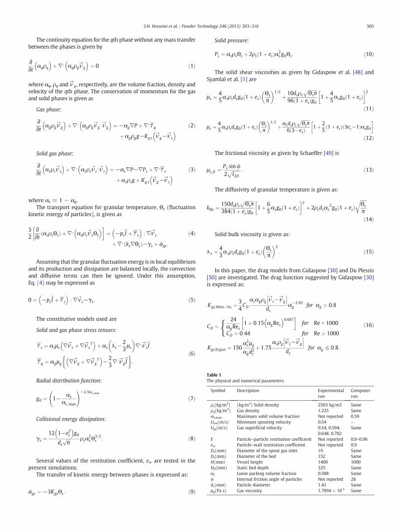
Table 1The physical and numerical parameters.
Symbol Description Experimentalrun
Computerrun
ρs(kg/m3) (kg/m3) Solid density 2503 kg/m3 Sameρg(kg/m3) Gas density 1.225 Sameαs,max Maximum solid volume fraction Not reported 0.59Ums(m/s) Minimum spouting velocity 0.54 –
Ugs(m/s) Gas superficial velocity 0.54, 0.594,0.648, 0.702
Same
E Particle–particle restitution coefficient Not reported 0.9–0.96ew Particle–wall restitution coefficient Not reported 0.9Ds(mm) Diameter of the spout gas inlet 19 SameDt(mm) Diameter of the bed 152 SameH(mm) Vessel height 1400 1000H0(mm) Static bed depth 325 Sameαs Loose packing volume fraction 0.588 Sameϕ Internal friction angle of particles Not reported 28ds(mm) Particle diameter 1.41 Sameμg(Pa s) Gas viscosity 1.7894 × 10 5 Same
305S.H. Hosseini et al. / Powder Technology 246 (2013) 303–316
The continuity equation for the qth phase without anymass transferbetween the phases is given by
∂∂t αqρq
� �þ∇⋅ αqρqν
→q
� �¼ 0 ð1Þ
where αq, ρq and ν→
q, respectively, are the volume fraction, density andvelocity of the qth phase. The conservation of momentum for the gasand solid phases is given as
Gas phase:
∂∂t αgρgν
→g
� �þ∇⋅ αgρgν
→g⋅ν
→g
� �¼ −αg∇P þ∇⋅τ g
þ αgρgg−Kg s ν→
g−ν→
s
� � ð2Þ
Solid gas phase:
∂∂t αsρsν
→s
� �þ∇⋅ αsρsν
→s⋅ν
→s
� �¼ −αs∇P−∇Ps þ∇⋅τ s
þ αsρsg þ Kg s ν→
g−ν→
s
� � ð3Þ
where αs = 1 − αg.The transport equation for granular temperature, Θs (fluctuation
kinetic energy of particles), is given as
32
∂∂t αsρsΘsð Þ þ∇⋅ αsρsν
→sΘs
� �� �¼ −psI þ τ s
� �: ∇ν
→s
þ∇⋅ ks∇Θsð Þ−γs þ ϕgs:
ð4Þ
Assuming that the granular fluctuation energy is in local equilibriumand its production and dissipation are balanced locally, the convectionand diffusive terms can then be ignored. Under this assumption,Eq. (4) may be expressed as
0 ¼ −psI þ τ s
� �: ∇v
→s−γs: ð5Þ
The constitutive models used are
Solid and gas phase stress tensors:
τ s ¼ αsμs ∇ν→
s þ∇ν→
sT
� �þ αs λs−
23μs
� �∇⋅ν→sI
τ g ¼ αgμg ∇ν→
g þ∇ν→
gT
� �−2
3∇⋅ν→gI
� :
ð6Þ
Radial distribution function:
g0 ¼ 1− αs
αs;max
!−2:5αs;max
ð7Þ
Collisional energy dissipation:
γs ¼12 1−e2s� �
g0
dsffiffiffiπ
p ρsα2sΘ
3=2s : ð8Þ
Several values of the restitution coefficient, es, are tested in thepresent simulations.
The transfer of kinetic energy between phases is expressed as:
ϕgs ¼ −3KgsΘs: ð9Þ
Solid pressure:
Ps ¼ αsρsΘs þ 2ρs 1þ esð Þα2s g0Θs: ð10Þ
The solid shear viscosities as given by Gidaspow et al. [48] andSyamlal et al. [1] are
μs ¼45αsρsdsg0 1þ esð Þ Θs
π
� �1=2þ 10dsρs
ffiffiffiffiffiffiffiffiΘsπ
p96 1þ esð Þg0
1þ 45αsg0 1þ esð Þ
� �2ð11Þ
μs ¼45αsρsdsg0 1þ esð Þ Θs
π
� �1=2þ αsdsρs
ffiffiffiffiffiffiffiffiΘsπ
p6 3−esð Þ 1þ 2
51þ esð Þ 3es−1ð Þαsg0
� �:
ð12Þ
The frictional viscosity as given by Schaeffer [49] is
μs; fr ¼Ps sinϕ2
ffiffiffiffiffiffiffiI2D
p : ð13Þ
The diffusivity of granular temperature is given as:
kΘs ¼150dsρs
ffiffiffiffiffiffiffiffiΘsπ
p384 1þ esð Þg0
1þ 65αsg0 1þ esð Þ
� �2þ 2ρsdsαs
2g0 1þ esð ÞffiffiffiffiffiffiΘs
π
r:
ð14Þ
Solid bulk viscosity is given as:
λ s ¼43α sρsdsg0 1þ esð Þ Θs
π
� �2: ð15Þ
In this paper, the drag models from Gidaspow [30] and Du Plessis[50] are investigated. The drag function suggested by Gidaspow [30]is expressed as:
Kgs;Wen�Yu ¼ 34CD
αsαgρg ν→
s−ν→
g
��� ���ds
α−2:65g for αg > 0:8
CD ¼ f 24αgRes
1þ 0:15 αgRes� �0:687� �
for Re b 1000
CD ¼ 0:44 for Re > 1000
Kgs;Ergun ¼ 150α2s μg
αgd2sþ 1:75
αsρg ν→
s−ν→
g
��� ���ds
for αg ≤ 0:8:
ð16Þ
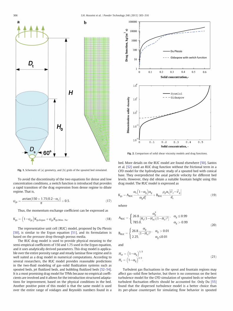
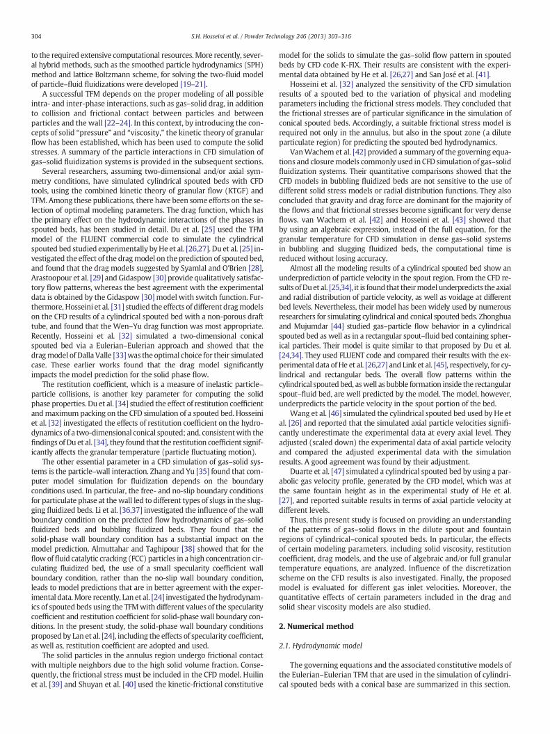
Fig. 1. Schematic of (a) geometry, and (b) grids of the spouted bed simulated.
Fig. 2. Comparison of solid shear viscosity models and drag functions.
306 S.H. Hosseini et al. / Powder Technology 246 (2013) 303–316
To avoid the discontinuity of the two equations for dense and lowconcentration conditions, a switch function is introduced that providesa rapid transition of the drag expression from dense regime to diluteregime. That is,
φgs ¼arctan 150� 1:75 0:2−αsð Þ½ �
πþ 0:5: ð17Þ
Thus, the momentum exchange coefficient can be expressed as
Kgs ¼ 1−φgs
� �Kgs;Ergun þ φgsKgs;Wen�Yu: ð18Þ
The representative unit cell (RUC) model, proposed by Du Plessis[50], is similar to the Ergun equation [51], and its formulation isbased on the pressure drop through porous media.
The RUC drag model is used to provide physical meaning to thesemi-empirical coefficients of 150 and 1.75 used in the Ergun equation,and it uses analytically derived parameters. This drag model is applica-ble over the entire porosity range and steady laminar flow regime and iswell suited as a drag model in numerical computations. According toseveral researchers, the RUC model provides reasonable predictionsin the two-fluid modeling of gas–solid fluidization systems such asspouted beds, jet fluidized beds, and bubbling fluidized beds [52–54].It is a most promising drag model for TFMs because no empirical coeffi-cients are involved and it allows for the introduction structured adapta-tions for improvement, based on the physical conditions in the bed.Another positive point of this model is that the same model is usedover the entire range of voidages and Reynolds numbers found in a
bed. More details on the RUC model are found elsewhere [50]. Santoset al. [52] used an RUC drag function without the frictional term in aCFD model for the hydrodynamic study of a spouted bed with conicalbase. They overpredicted the axial particle velocity for different bedlevels. However, they did obtain a suitable fountain height using thisdrag model. The RUC model is expressed as
Kgs ¼ ARUC
αs 1−αg
� �αg
αgd2s
þ BRUC
ρgαs ν→
s−ν→
g
��� ���ds
ð19Þ
where
ARUC ¼ f26:8α3g
He 1−Hetð Þ 1−Heð Þ2� ; αg ≤ 0:99
785:0; αg > 0:99
BRUC ¼ 26:8αg
1−Heð Þ2 ; αg > 0:01
2:25; αg≤0:01
8<:
ð20Þ
and
Het ¼ 1−αg
� �1=3He ¼ 1−αg
� �2=3:
ð21Þ
Turbulent gas fluctuations in the spout and fountain regions mayaffect gas–solid flow behavior, but there is no consensus on the bestturbulence model for the CFD simulation of spouted beds or whetherturbulent fluctuation effects should be accounted for. Only Du [55]found that the dispersed turbulence model is a better choice thanits per-phase counterpart for simulating flow behavior in spouted

Table 2Fountain heights, maximum particle velocities along the bed axis for different solidshear viscosity models.
Items Experimentaldata
Predicted results
Viscosity model ofGidaspow et al.[48]
Viscosity modelof Syamlal et al.[1]
Maximum particle velocitiesalong the bed axis, m/s
5.67 3.19 3.95
Fountain heights, m 0.25 0.105 0.165
307S.H. Hosseini et al. / Powder Technology 246 (2013) 303–316
beds. Therefore, the dispersed turbulence model is adopted in thisstudy, where turbulence predictions for the gas phase are obtainedby the standard k–ε model.
2.2. Simulation conditions
The experimental data of He et al. [26,27] for a cylindrical spoutedbed with conical base are used to validate the present model. Theyused afiber optic probe tomeasure particle velocities aswell as voidagesin a spouted bed. A detailed description of the experimental setup andthe spouted bed studied was reported by He et al. [26,27]. The corre-sponding physical and numerical parameters selected for the presentsimulation are listed in Table 1. The flow in the freeboard above thebed is assumed to be fully developed and, to fulfill this condition, thevertical dimension of the bed must be sufficiently high. Hence, in thesimulation carried out, a bed height of 1.0 m is deemed to be sufficient.
2.3. Solution procedure
A commercial grid-generation tool, GAMBIT 2.2, is used to createthe two-dimensional geometry and computational grid. In addition,the CFD code FLUENT 6.3 is used to simulate the hydrodynamicsof the cylindrical spouted bed studied by He et al. [26,27]. The set ofgoverning equations described in Section 2.1 is solved by a finitecontrol volume technique.
The phase-coupled PC-SIMPLE algorithm is used for the pressure–velocity coupling. Cammarata et al. [56] investigated the consistency oftwo- and three-dimensional simulations. They recommend using thetwo-dimensional/axisymmetric models for reducing the computationaltime when the gas–solid flow behavior is close to two-dimensionalor when axisymmetric and three-dimensional out-of-plane motion arenegligible. In this study, axial symmetry is assumed, and an axisymmetriccomputational model is used in the simulation. A second-order upwind
Fig. 3. Contour plots of solid volume fraction in the bed for U = 1.2Ums, es = 0.9, thealgebraic equation for granular temperature, the Gidaspow drag model [30] and (a): theGidaspow et al. [48] viscosity model, and (b): the Syamlal et al. [1] viscosity model.
discretization scheme is used for momentum, turbulence kinetic energyand turbulence dissipation rate equations; and a first-order upwindscheme is only used for the volume fraction term. Transient simulationsare performed with a constant time step of 0.0001 s with 30 iterationsper time step. A convergence criterion of 10−3 for each scaled residualcomponent is used for the relative error between two iterations. A gridresolution of 36 × 180 was used in this study, which is the same as thatof Lan et al. [24]. The bed and grid structures for the computationaldomain are illustrated, respectively, in Fig. 1a and b.
2.4. Initial and boundary conditions
The Dirichlet boundary conditions at the bottom of the bed (nozzle)are used to specify a uniform gas inlet velocity. The gas enters throughthe nozzle in the axial direction. Thus, the inlet gas velocity is given asux,0 = 0 and uy,0 = U.
As mentioned before, the outflow condition with zero velocitygradients is specified at the top of the freeboard. At the axis of thespouted bed, the velocity gradients for both phases and the granulartemperature gradient along the radial direction are zero. A no-slipboundary condition at the lateral bed wall is assumed for the gasphase. The particle normal velocity is set to zero at thewall. The Johnson
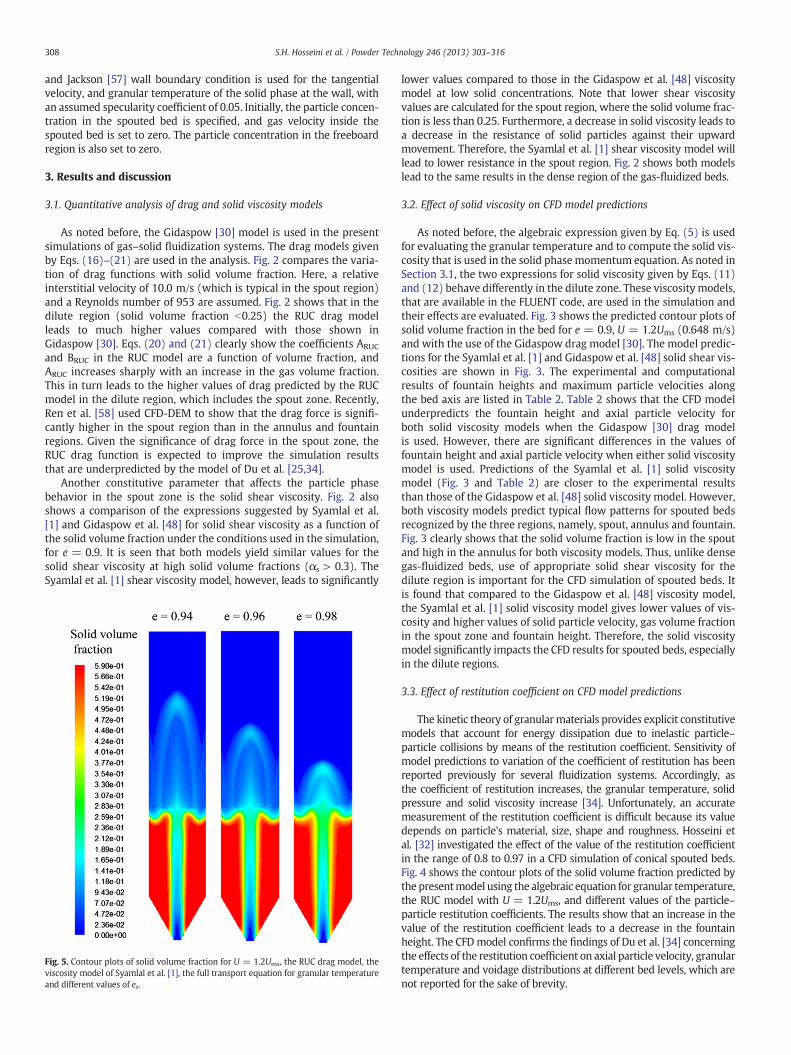
Fig. 4. Contour plots of solid volume fraction for U = 1.2Ums, the RUC drag model, theviscosity model of Syamlal et al. [1], the algebraic equation for granular temperatureand different values of es.
308 S.H. Hosseini et al. / Powder Technology 246 (2013) 303–316
and Jackson [57] wall boundary condition is used for the tangentialvelocity, and granular temperature of the solid phase at the wall, withan assumed specularity coefficient of 0.05. Initially, the particle concen-tration in the spouted bed is specified, and gas velocity inside thespouted bed is set to zero. The particle concentration in the freeboardregion is also set to zero.
3. Results and discussion
3.1. Quantitative analysis of drag and solid viscosity models
As noted before, the Gidaspow [30] model is used in the presentsimulations of gas–solid fluidization systems. The drag models givenby Eqs. (16)–(21) are used in the analysis. Fig. 2 compares the varia-tion of drag functions with solid volume fraction. Here, a relativeinterstitial velocity of 10.0 m/s (which is typical in the spout region)and a Reynolds number of 953 are assumed. Fig. 2 shows that in thedilute region (solid volume fraction b0.25) the RUC drag modelleads to much higher values compared with those shown inGidaspow [30]. Eqs. (20) and (21) clearly show the coefficients ARUC
and BRUC in the RUC model are a function of volume fraction, andARUC increases sharply with an increase in the gas volume fraction.This in turn leads to the higher values of drag predicted by the RUCmodel in the dilute region, which includes the spout zone. Recently,Ren et al. [58] used CFD-DEM to show that the drag force is signifi-cantly higher in the spout region than in the annulus and fountainregions. Given the significance of drag force in the spout zone, theRUC drag function is expected to improve the simulation resultsthat are underpredicted by the model of Du et al. [25,34].
Another constitutive parameter that affects the particle phasebehavior in the spout zone is the solid shear viscosity. Fig. 2 alsoshows a comparison of the expressions suggested by Syamlal et al.[1] and Gidaspow et al. [48] for solid shear viscosity as a function ofthe solid volume fraction under the conditions used in the simulation,for e = 0.9. It is seen that both models yield similar values for thesolid shear viscosity at high solid volume fractions (αs > 0.3). TheSyamlal et al. [1] shear viscosity model, however, leads to significantly
Fig. 5. Contour plots of solid volume fraction for U = 1.2Ums, the RUC drag model, theviscosity model of Syamlal et al. [1], the full transport equation for granular temperatureand different values of es.
lower values compared to those in the Gidaspow et al. [48] viscositymodel at low solid concentrations. Note that lower shear viscosityvalues are calculated for the spout region, where the solid volume frac-tion is less than 0.25. Furthermore, a decrease in solid viscosity leads toa decrease in the resistance of solid particles against their upwardmovement. Therefore, the Syamlal et al. [1] shear viscosity model willlead to lower resistance in the spout region. Fig. 2 shows both modelslead to the same results in the dense region of the gas-fluidized beds.
3.2. Effect of solid viscosity on CFD model predictions
As noted before, the algebraic expression given by Eq. (5) is usedfor evaluating the granular temperature and to compute the solid vis-cosity that is used in the solid phase momentum equation. As noted inSection 3.1, the two expressions for solid viscosity given by Eqs. (11)and (12) behave differently in the dilute zone. These viscosity models,that are available in the FLUENT code, are used in the simulation andtheir effects are evaluated. Fig. 3 shows the predicted contour plots ofsolid volume fraction in the bed for e = 0.9, U = 1.2Ums (0.648 m/s)and with the use of the Gidaspow drag model [30]. The model predic-tions for the Syamlal et al. [1] and Gidaspow et al. [48] solid shear vis-cosities are shown in Fig. 3. The experimental and computationalresults of fountain heights and maximum particle velocities alongthe bed axis are listed in Table 2. Table 2 shows that the CFD modelunderpredicts the fountain height and axial particle velocity forboth solid viscosity models when the Gidaspow [30] drag modelis used. However, there are significant differences in the values offountain height and axial particle velocity when either solid viscositymodel is used. Predictions of the Syamlal et al. [1] solid viscositymodel (Fig. 3 and Table 2) are closer to the experimental resultsthan those of the Gidaspow et al. [48] solid viscosity model. However,both viscosity models predict typical flow patterns for spouted bedsrecognized by the three regions, namely, spout, annulus and fountain.Fig. 3 clearly shows that the solid volume fraction is low in the spoutand high in the annulus for both viscosity models. Thus, unlike densegas-fluidized beds, use of appropriate solid shear viscosity for thedilute region is important for the CFD simulation of spouted beds. Itis found that compared to the Gidaspow et al. [48] viscosity model,the Syamlal et al. [1] solid viscosity model gives lower values of vis-cosity and higher values of solid particle velocity, gas volume fractionin the spout zone and fountain height. Therefore, the solid viscositymodel significantly impacts the CFD results for spouted beds, especiallyin the dilute regions.
3.3. Effect of restitution coefficient on CFD model predictions
The kinetic theory of granularmaterials provides explicit constitutivemodels that account for energy dissipation due to inelastic particle–particle collisions by means of the restitution coefficient. Sensitivity ofmodel predictions to variation of the coefficient of restitution has beenreported previously for several fluidization systems. Accordingly, asthe coefficient of restitution increases, the granular temperature, solidpressure and solid viscosity increase [34]. Unfortunately, an accuratemeasurement of the restitution coefficient is difficult because its valuedepends on particle's material, size, shape and roughness. Hosseini etal. [32] investigated the effect of the value of the restitution coefficientin the range of 0.8 to 0.97 in a CFD simulation of conical spouted beds.Fig. 4 shows the contour plots of the solid volume fraction predicted bythe presentmodel using the algebraic equation for granular temperature,the RUC model with U = 1.2Ums, and different values of the particle–particle restitution coefficients. The results show that an increase in thevalue of the restitution coefficient leads to a decrease in the fountainheight. The CFDmodel confirms the findings of Du et al. [34] concerningthe effects of the restitution coefficient on axial particle velocity, granulartemperature and voidage distributions at different bed levels, which arenot reported for the sake of brevity.
309S.H. Hosseini et al. / Powder Technology 246 (2013) 303–316
Lan et al. [24] suggested that the fountain height is a key parameterthat can be used to determine the accuracy of the numerical models fordescribing the hydrodynamic behavior of spouted beds. A value of 0.90for the restitution coefficient leads to a full accordance between theCFD results and the experimental data [26] in terms of fountain height(fountain height of 0.25 m for both experimental and computationalresults). It should be noted that such a method is used for selectingthe restitution coefficient when evaluating the complete transportequation for granular temperature in the model.
Fig. 5 shows contour plots of solid volume fraction as predicted bythe model using the full transport equation for granular temperatureand RUC model with U = 1.2Ums and three values of the particle–particle restitution coefficients (e = 0.94, 0.96 and 0.98). The resultsreveal that an increase in the value of the restitution coefficient leadsto a decrease in the fountain height and an increase of solid concen-tration in the spout and fountain zones. From Fig. 13, it is seen thata value of 0.96 for the restitution coefficient as suggested by Lan etal. [24], leads to a predicted fountain height which is the same asthe experimental value when the full transport equation for granulartemperature is used.
3.4. Effect of drag function on the CFD model predictions
Here, the algebraic expression given by Eq. (5) for granular tem-perature, the solid shear viscosity of Syamlal et al. [1], e = 0.9 andU = 1.2Ums are used. The effects of changing the drag model are ana-lyzed. The drag model of Gidaspow including a switch function and theRUC drag model are implemented by means of user-defined functions(UDF) (which are written in C-code and compiled in FLUENT).
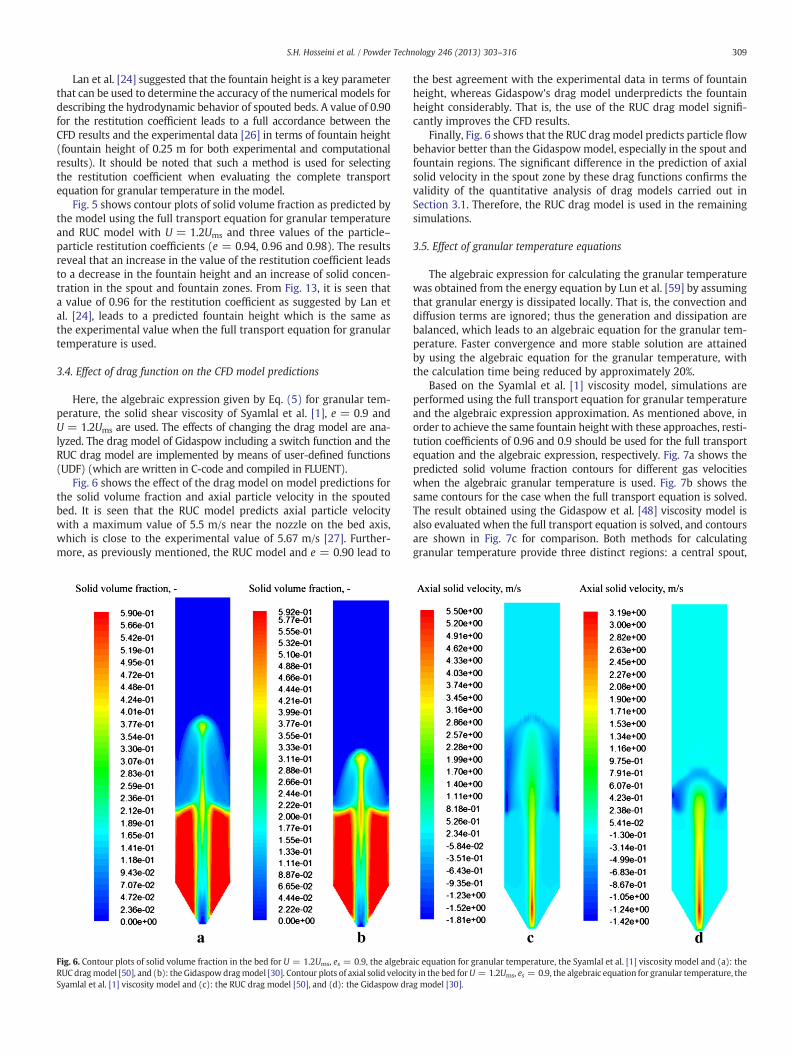
Fig. 6 shows the effect of the drag model on model predictions forthe solid volume fraction and axial particle velocity in the spoutedbed. It is seen that the RUC model predicts axial particle velocitywith a maximum value of 5.5 m/s near the nozzle on the bed axis,which is close to the experimental value of 5.67 m/s [27]. Further-more, as previously mentioned, the RUC model and e = 0.90 lead to
Fig. 6. Contour plots of solid volume fraction in the bed for U = 1.2Ums, es = 0.9, the algebraRUC dragmodel [50], and (b): the Gidaspowdragmodel [30]. Contour plots of axial solid velocitSyamlal et al. [1] viscosity model and (c): the RUC drag model [50], and (d): the Gidaspow dra
the best agreement with the experimental data in terms of fountainheight, whereas Gidaspow's drag model underpredicts the fountainheight considerably. That is, the use of the RUC drag model signifi-cantly improves the CFD results.
Finally, Fig. 6 shows that the RUC drag model predicts particle flowbehavior better than the Gidaspowmodel, especially in the spout andfountain regions. The significant difference in the prediction of axialsolid velocity in the spout zone by these drag functions confirms thevalidity of the quantitative analysis of drag models carried out inSection 3.1. Therefore, the RUC drag model is used in the remainingsimulations.
3.5. Effect of granular temperature equations
The algebraic expression for calculating the granular temperaturewas obtained from the energy equation by Lun et al. [59] by assumingthat granular energy is dissipated locally. That is, the convection anddiffusion terms are ignored; thus the generation and dissipation arebalanced, which leads to an algebraic equation for the granular tem-perature. Faster convergence and more stable solution are attainedby using the algebraic equation for the granular temperature, withthe calculation time being reduced by approximately 20%.
Based on the Syamlal et al. [1] viscosity model, simulations areperformed using the full transport equation for granular temperatureand the algebraic expression approximation. As mentioned above, inorder to achieve the same fountain height with these approaches, resti-tution coefficients of 0.96 and 0.9 should be used for the full transportequation and the algebraic expression, respectively. Fig. 7a shows thepredicted solid volume fraction contours for different gas velocitieswhen the algebraic granular temperature is used. Fig. 7b shows thesame contours for the case when the full transport equation is solved.The result obtained using the Gidaspow et al. [48] viscosity model isalso evaluated when the full transport equation is solved, and contoursare shown in Fig. 7c for comparison. Both methods for calculatinggranular temperature provide three distinct regions: a central spout,
ic equation for granular temperature, the Syamlal et al. [1] viscosity model and (a): they in the bed forU = 1.2Ums, es = 0.9, the algebraic equation for granular temperature, theg model [30].
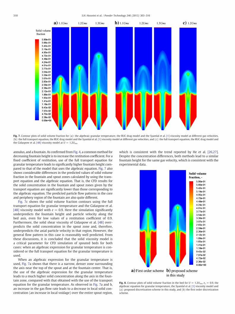
Fig. 8. Contour plots of solid volume fraction in the bed for U = 1.2Ums, es = 0.9, thealgebraic equation for granular temperature, the Syamlal et al. [1] viscosity model and(a): proposed discretization scheme in this study, and (b) the first order discretizationscheme.
Fig. 7. Contour plots of solid volume fraction for (a): the algebraic granular temperature, the RUC drag model and the Syamlal et al. [1] viscosity model at different gas velocities,(b): the full transport equation, the RUC drag model and the Syamlal et al. [1] viscosity model at different gas velocities, and (c): the full transport equation, the RUC drag model andthe Gidaspow et al. [48] viscosity model at U = 1.2Ums.
310 S.H. Hosseini et al. / Powder Technology 246 (2013) 303–316
annulus, and a fountain. As confirmed fromFig. 4, a commonmethod fordecreasing fountain height is to increase the restitution coefficient. For afixed coefficient of restitution, use of the full transport equation forgranular temperature leads to significantly higher fountain height com-pared to that of the model that uses the algebraic equation. Fig. 7 alsoshows considerable differences in the predicted values of solid volumefraction in the fountain and spout zones calculated by using the trans-port equation and the algebraic equation. That is, the CFD results forthe solid concentration in the fountain and spout zones given by thetransport equation are significantly lower than those corresponding tothe algebraic equation. The predicted particle flow patterns in the coreand periphery region of the fountain are also quite different.
Fig. 7c shows the solid volume fraction contours using the fulltransport equation for granular temperature and the Gidaspow et al.[48] viscosity model with e = 0.9. Here the simulation significantlyunderpredicts the fountain height and particle velocity along thebed axis, even for low values of a restitution coefficient of 0.9.Furthermore, the solid shear viscosity of Gidaspow et al. [48] over-predicts the solid concentration in the spout zone and, therefore,underpredicts the axial particle velocity in that region. However, thegeneral flow pattern in this case is reasonably well predicted. Fromthese discussions, it is concluded that the solid viscosity model isa critical parameter for CFD simulation of spouted beds for bothcases: when an algebraic expression for granular temperature is con-sidered or the full transport equation for the granular temperature isused.
When an algebraic expression for the granular temperature isused, Fig. 7a shows that there is a narrow, denser zone surroundingthe axis near the top of the spout and at the fountain center. That is,the use of the algebraic expression for the granular temperatureleads to a much higher solid concentration along the axis in the foun-tain zone, compared with that obtained with the use of the transportequation for the granular temperature. As observed in Fig. 7a and b,an increase in the gas flow rate leads to a decrease in local solid con-centration (an increase in local voidage) over the entire spout region,
which is consistent with the trend reported by He et al. [26,27].Despite the concentration differences, both methods lead to a similarfountain height for the same gas velocity, which is consistent with theexperimental data.

311S.H. Hosseini et al. / Powder Technology 246 (2013) 303–316
3.6. Effect of discretization scheme
Discretization is a process by which the governing partial differen-tial equations are converted to algebraic equations for numerical solu-tion. As noted before, we used the second-order upwind scheme for thediscretization of the momentum equation, and transport equationsfor turbulence kinetic energy and turbulence dissipation rate. Thefirst-order upwind scheme was used only for the volume fractionterm. Such a choice has been already used by several authors includingHosseini et al. [61], Bettega et al. [62], and Behjat et al. [63] for CFD sim-ulation of fluidization systems. Fig. 8 shows a comparison between theselected schemes in the present study and the first-order discretizationfor all terms which was recently used by Lan et al. [24]. Here forthe present study, the viscosity model of Syamlal et al. [1], algebraicgranular temperature, restitution coefficient of 0.9, and the RUC dragmodel for U = 1.2Ums are used. This figure shows that with the useof a second-order discretization scheme, the fountain height is reason-ably predicted. Moreover, the maximum value for the axial particle ve-locity near the nozzle on the bed axis is 4.25, 5.5 and 5.67 m/s,respectively, for the first-order upwind scheme, second-order scheme
Fig. 9. Experimental and computational results for the radial voidage d
used in the current work, and the experimental data [27]. Clearly, thefirst-order scheme underpredicts the fountain height and axial particlevelocity. The second-order scheme, however, predicts results that aremuch closer to the experimental data. It is perhaps worth mentioningthat for simulation of a conical spouted bed, Wang [64] showed thatthe modeling results of the second-order scheme for the momentumequation are in fair agreement with the experimental findings,compared to the first-order scheme. Therefore, the use of second-order discretization scheme for CFD simulation of spouted bed isrecommended.
3.7. Investigation of several hydrodynamic parameters in the spout andfountain regions
Fig. 9 shows the model predictions for the radial voidage distributionat different fountain levels for U = 1.1Ums, U = 1.2Ums and U = 1.3Ums.Here, the viscosity model of Syamlal et al. [1], algebraic granular temper-ature, a restitution coefficient of 0.9, and the RUC drag model are used.The experimental data of He [60] are reproduced in this figure for com-parison. In Fig. 9, ZF is the vertical coordinate in the fountain measured
istribution at different fountain levels and different gas velocities.
312 S.H. Hosseini et al. / Powder Technology 246 (2013) 303–316
from the bed surface. It is observed from both computational results andexperimental data that the solid volume fraction is higher in the core re-gion and gradually decreases as the radial distance from the axis in-creases. The solid concentration in the core region also decreases as thefountain level increases, except near the top of the fountain, where thetrend is reversed. According to Fig. 9, the solid concentration in the foun-tain zone is sensitive to gas velocity; that is, the concentration decreasesas spouting gas velocity increases. The CFD results of the full transportequation related to solid concentration in the fountain zone are notshown in Fig. 9b to avoidmaking the figure too crowded. Fig. 7b, howev-er, shows that the full transport equation for granular temperature withthe viscositymodel of Syamlal et al. [1] underpredicts the solid concentra-tion in the fountain zone.
The particle dense zone is most noticeable for U = 1.1Ums with auniform value in the core region of the fountain.
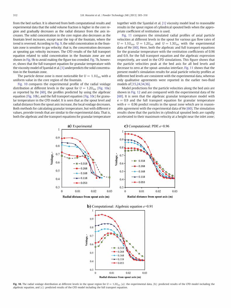
Fig. 10 compares the experimental profile of the radial voidagedistribution at different levels in the spout for U = 1.2Ums (Fig. 10a)as reported by He [60], the profiles predicted by using the algebraicequation (Fig. 10b), and the full transport equation (Fig. 10c) for granu-lar temperature in the CFD model. It is seen that as the spout level andradial distance from the spout axis increase, the local voidage decreases.Bothmethods for calculating granular temperature, but with different evalues, provide trends that are similar to the experimental data. That is,both the algebraic and the transport equations for granular temperature
Fig. 10. The radial voidage distribution at different levels in the spout region for U = 1.2Ualgebraic equation, and (c): predicted results of the CFD model including the full transport
together with the Syamlal et al. [1] viscosity model lead to reasonableresults in the spout region of cylindrical spouted beds when the appro-priate coefficient of restitution is used.
Fig. 11 compares the simulated radial profiles of axial particlevelocities at different levels in the spout for various gas flow rates ofU = 1.1Ums, U = 1.2Ums and U = 1.3Ums with the experimentaldata of He [60]. Here, both the algebraic and full transport equationsfor the granular temperature with the restitution coefficients of 0.96and 0.9, for the full transport equation and the algebraic expressionrespectively, are used in the CFD simulations. This figure shows thatthe particle velocities peak at the bed axis for all bed levels anddecrease to zero at the spout–annulus interface. Fig. 11 shows that thepresent model's simulation results for axial particle velocity profiles atdifferent bed levels are consistent with the experimental data, whereasonly qualitative agreements were reported in the earlier two-fluidmodels of [15,24,34,36].
Model predictions for the particle velocities along the bed axis areshown in Fig. 12 and are compared with the experimental data of He[60]. It is seen that the algebraic granular temperature model withe = 0.9 and the full transport equation for granular temperaturewith e = 0.96 predict results in the spout zone which are in reason-able agreement with the experimental data of He [60]. The simulationresults show that the particles in cylindrical spouted beds are rapidlyaccelerated to their maximum velocity at a height near the inlet zone;
ms (a): the experimental data, (b): predicted results of the CFD model including theequation.

Fig. 11. The experimental and simulated radial distributions of axial particle velocity at different levels in the spout for various gas flow rates.
313S.H. Hosseini et al. / Powder Technology 246 (2013) 303–316
then they gradually decelerate, and their velocity drops sharply tozero in the fountain region. This trend is greatly different from thatobserved in conical spouted beds. Hosseini et al. [32] showed that in
the conical spouted beds the particles are quickly accelerated nearthe inlet zone, and then the particle velocity profile stays roughlyflat for a conical spouted bed.
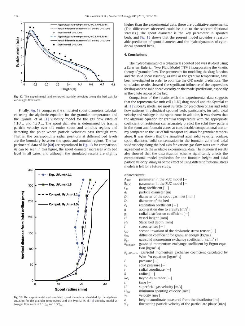
Fig. 12. The experimental and computed particle velocities along the bed axis forvarious gas flow rates.
314 S.H. Hosseini et al. / Powder Technology 246 (2013) 303–316
Finally, Fig. 13 compares the simulated spout diameters calculat-ed using the algebraic equation for the granular temperature andthe Syamlal et al. [1] viscosity model for the gas flow rates of1.1Ums and 1.3Ums. The spout diameter is determined by tracingparticle velocity over the entire spout and annulus regions anddetecting the point where particle velocities pass through zero.That is, the corresponding radial positions at different bed levelsare the boundary between the spout and annulus regions. The ex-perimental data of He [60] are reproduced in Fig. 13 for comparison.As can be seen in this figure, the spout diameter increases with bedlevel in all cases, and although the simulated results are slightly
Fig. 13. The experimental and simulated spout diameters calculated by the algebraicequation for the granular temperature and the Syamlal et al. [1] viscosity model attwo gas flow rates of 1.1Ums and 1.3Ums.
higher than the experimental data, there are qualitative agreements.(The differences observed could be due to the selected frictionalstresses.) The spout diameter is the key parameter in spoutedbeds, and Fig. 13 shows that the present model provides a reason-able prediction of spout diameter and the hydrodynamics of cylin-drical spouted beds.
4. Conclusions
The hydrodynamics of a cylindrical spouted bed was studied usinga Eulerian–Eulerian Two-Fluid Model (TFM) incorporating the kinetictheory of granular flow. The parameters for modeling the drag functionand the solid shear viscosity, as well as the granular temperature, havebeen investigated in order to optimize the CFD model predictions. Thesimulation results showed the significant influence of the expressionsfor drag and the solid shear viscosity on themodel predictions, especiallyin the dilute region of the bed.
Comparison of the results with the experimental data suggeststhat the representative unit cell (RUC) drag model and the Syamlal etal. [1] viscosity model are most suitable for prediction of gas and solidflow patterns in cylindrical spouted beds, particularly, for solid axialvelocity and voidage in the spout zone. In addition, it was shown thatthe algebraic equation for granular temperature with the appropriatecoefficient of restitution can accurately predict the solid flow patternin the spout and fountain zones at considerable computational econo-my compared to the use of full transport equation for granular temper-ature. It was shown that the simulated axial solid velocity, voidage,spout diameter, solid concentration in the fountain zone and axialsolid velocity along the bed axis for various gas flow rates are in closeagreement with the available experimental data. The numerical resultsalso showed that the discretization scheme significantly affects thecomputational model prediction for the fountain height and axialparticle velocity. Analysis of the effect of using different frictional stressmodels is left for a future study.
NomenclatureARUC parameter in the RUC model [−]BRUC parameter in the RUC model [−]CD drag coefficient [−]ds particle diameter [m]Ds diameter of the spout gas inlet [mm]Dt diameter of the bedes restitution coefficient [−]g acceleration due to gravity [m/s2]g0 radial distribution coefficient [−]H vessel height [mm]H0 Static bed depth [mm]I stress tensor [−]I2D second invariant of the deviatoric stress tensor [−]kΘs diffusion coefficient for granular energy [kg/m s]Kgs gas/solid momentum exchange coefficient [kg/m3 s]Kgs,Ergun gas/solid momentum exchange coefficient by Ergun equa-
tion [kg/m3 s]Kgs,Wen–Yu gas/solid momentum exchange coefficient calculated by
Wen–Yu equation [kg/m3 s]P pressure [−]Ps solid pressure [−]r radial coordinate [−]R radius [−]Res Reynolds number [−]t time [−]U superficial gas velocity [m/s]Ums minimum spouting velocity [m/s]vi velocity [m/s]z height coordinate measured from the distributor [m]v′s fluctuating particle velocity of the particulate phase [m/s]
315S.H. Hosseini et al. / Powder Technology 246 (2013) 303–316
Greek lettersαi volume fraction [−]γs the collisional dissipation of energy [kg/s3 m]Θs granular temperature [m2/s2]λs solid bulk viscosity [kg/m s]μi shear viscosity [kg/m s]ρi density [kg/m3]τ i stress tensor [Pa]ϕ angle of internal friction [deg]ϕgs transfer rate of kinetic energy [kg/s3 m]
Subscriptsfr frictiong gasi general indexms minimum spoutingp particleq phase type (solid or gas)s solidsT stress tensor
References
[1] M. Syamlal, W. Rogers, T.J. O'Brien, MFIX Documentation: Volume 1, Theory Guide,National Technical Information Service, Springfield, VA, 1993. (DOE/METC-9411004,NTIS/DE9400087).
[2] K.B. Mathur, P.E. Gishler, A technique for contacting gases with coarse solid particles,AICHE Journal 1 (1955) 157–164.
[3] R.G. Szafran, A. Kmiec, CFD modeling of heat and mass transfer in a spouted beddryer, Industrial and Engineering Chemistry Research 43 (2004) 1113–1124.
[4] H. Ichikawa, M. Arimoto, Y. Fukumori, Design of microcapsules with hydrogel as amembrane component and their preparation by spouted bed, Powder Technology130 (2003) 189–192.
[5] L.A.P. Freitas, J.T. Freire, Experimental study on the dynamics of a spouted bedwith particle feed through the base, Brazilian Journal of Chemical Engineering14 (1997) 269–280.
[6] K. Jono, H. Ichikawa, M. Miyamoto, Y. Fukumori, A review of particulate design forpharmaceutical powders and their production by spouted bed coating, PowderTechnology 113 (2000) 269–277.
[7] M. Olazar, R. Aguado, J.L. Sánchez, R. Bilbao, J. Arauzo, Thermal processing ofstraw black liquor in fluidized and spouted bed, Energy & Fuels 16 (2002)1417–1424.
[8] M. Olazar, M.J. San José, G. Zabala, J. Bilbao, New reactor in jet spouted bed regimefor catalytic polymerizations, Chemical Engineering Science 49 (1994) 4579–4588.
[9] M. Olazar, R. Aguado, A. Barona, J. Bilbao, Pyrolysis of sawdust in a conical spoutedbed reactor with a HZSM-5 catalyst, AICHE Journal 46 (2000) 1025–1033.
[10] Z. Deng, R. Xiao, B. Jin, H. Huang, L. Shen, Q. Song, Q. Li, Computational fluiddynamics modeling of coal gasification in a pressurized spout–fluid bed, Energy& Fuels 22 (2008) 1560–1569.
[11] G. Ahmadi, M. Farshad, On the continuum theory of solid–fluid mixture — asuperimposed model of equipresent constituents, Indian Journal of Technology12 (1974) 195–198.
[12] J.J. Monaghan, A. Kocharya, SPH simulation of multi-phase flow, Computer PhysicsCommunications 87 (1995) 225–235.
[13] J. Ma, W. Ge, Q. Xiong, J. Wang, J. Li, Direct numerical simulation of particleclustering in gas–solid flowwith amacro-scale particlemethod, Chemical EngineeringScience 64 (2009) 43–51.
[14] Q. Xiong, B. Li, F. Chen, J. Ma, W. Ge, J. Li, Direct numerical simulation of sub-gridstructures in gas–solid flow—GPU implementation of macro-scale pseudo-particlemodeling, Chemical Engineering Science 65 (2010) 5356–5365.
[15] L. Wang, G. Zhou, X.Wang, Q. Xiong,W. Ge, Direct numerical simulation of particle–fluid systems by combining time-driven hard-sphere model and lattice Boltzmannmethod, Particuology 8 (2010) 379–382.
[16] Q. Xiong, B. Li, G. Zhou, X. Fang, J. Xu, J. Wang, X. He, X. Wang, L. Wang, W. Ge, J. Li,Large-scale DNS of gas–solid flows on mole-8.5, Chemical Engineering Science 71(2012) 422–430.
[17] Q. Xiong, B. Li, J. Xu, X. Wang, L. Wang, W. Ge, Efficient 3D DNS of gas–solid flowson Fermi GPGPU, Computers and Fluids 70 (2012) 86–94.
[18] H. Nasr, G. Ahmadi, J.B. Mclaughlin, A DNS study of effects of particle–particlecollisions and two-way coupling on particle deposition and phasic fluctuations,Journal of Fluid Mechanics 640 (2009) 507–536.
[19] K. Sankaranarayanan, S. Sundaresan, Lattice Boltzmann simulation of two-fluidmodelequations, Industrial and Engineering Chemistry Research 47 (2008) 9165–9173.
[20] S. Melchionna, Incorporation of smooth spherical bodies in the lattice Boltzmannmethod, Journal of Computational Physics 230 (2011) 3966–3976.
[21] Q. Xiong, L. Deng, W. Wang, W. Ge, SPH method for two-fluid modeling of particle–fluid fluidization, Chemical Engineering Science 66 (2011) 1859–1865.
[22] S. Abu-Zaid, G. Ahmadi, A simple kinetic model for rapid granular flows includ-ing frictional losses, ASCE Journal of Engineering Mechanics 116 (1990)379–389.
[23] G. Ahmadi, D. Ma, A thermodynamical formulation for dispersed multiphaseturbulent flows, part I: basic theory, International Journal of Multiphase Flow16 (1990) 323–340.
[24] X. Lan, C. Xu, J. Gao, M. Al-Dahhan, Influence of solid-phase wall boundary conditionon CFD simulation of spouted beds, Chemical Engineering Science 69 (2012) 419–430.
[25] W. Du, X.J. Bao, J. Xu, W.S. Wei, Computational fluid dynamics (CFD) modeling ofspouted bed: assessment of drag coefficient correlations, Chemical EngineeringScience 61 (2006) 1401–1420.
[26] Y.L. He, C.J. Lim, J.R. Grace, J.X. Zhu, S.Z. Qin, Measurements of voidage profiles inspouted beds, Canadian Journal of Chemical Engineering 72 (1994) 229–234.
[27] Y.L. He, C.J. Lim, J.R. Grace, Particle velocity profiles and solid flow patterns inspouted beds, Canadian Journal of Chemical Engineering 72 (1994) 561–568.
[28] M. Syamlal, T.J. O'Brien, Simulation of granular layer inversion in liquid fluidizedbeds, International Journal of Multiphase Flow 14 (1988) 473–481.
[29] H. Arastoopour, P. Pakdel, M. Adewumi, Hydrodynamic analysis of dilute gas–solidsflow in a vertical pipe, Powder Technology 62 (1990) 163–170.
[30] D. Gidaspow, Multiphase Flow and Fluidization, Academic Press, San Diego, 1994.[31] S.H. Hosseini, M. Zivdar, R. Rahimi, CFD simulation of gas–solid flow in a spouted
bed with a non-porous draft tube, Chemical Engineering and Processing 48(2009) 1539–1548.
[32] S.H. Hosseini, G. Ahmadi, B.S. Razavi, W. Zhong, Computational fluid dynamicsimulation of hydrodynamic behavior in a two-dimensional conical spoutedbed, Energy & Fuels 24 (2010) 6086–6098.
[33] J.M. Dalla Valle, Micromeritics, Pitman, London, 1948.[34] W. Du, X.J. Bao, J. Xu, W.S. Wei, Computational fluid dynamics (CFD) modeling of
spouted bed: influence of frictional stress, maximum packing limit and coefficientof restitution of particles, Chemical Engineering Science 61 (2006) 4558–4570.
[35] S.J. Zhang, A.B. Yu, Computational investigation of slugging behaviour ingas-fluidised beds, Powder Technology 123 (2–3) (2002) 147–165.
[36] T. Li, Y. Zhang, J.R. Grace, X. Bi, Numerical investigation of gas mixing in gas–solidfluidized beds, AICHE Journal 56 (2010) 2280–2296.
[37] T. Li, J.R. Grace, X. Bi, Study of wall boundary condition in numerical simulationsof bubbling fluidized beds, Powder Technology 203 (2010) 447–457.
[38] A. Almuttahar, F. Taghipour, Computational fluid dynamics of high density circulatingfluidized bed riser: study of modeling parameters, Powder Technology 185 (1) (2008)11–23.
[39] L. Huilin, H. Yurong, L. Wentie, D. Jianmin, D. Gidaspow, J. Bouillard, Computersimulations of gas–solid flow in spouted beds using kinetic–frictional stressmodel of granular flow, Chemical Engineering Science 59 (2004) 865–878.
[40] W. Shuyan, L. Xiang, L. Huilin, Y. Long, S. Dan, H. Yurong, D. Yonglong, Numericalsimulations of flow behavior of gas and particles in spouted beds usingfrictional-kinetic stresses model, Powder Technology 196 (2009) 184–193.
[41] M.J. San José, M. Olazar, S. Alvarez, M.A. Izquierdo, J. Bilbao, Solid cross-flow intothe spout and particle trajectories in conical spouted beds, Chemical EngineeringScience 53 (1998) 3561–3570.
[42] B.G.M. van Wachem, J.C. Schouten, R. Krishna, C.M. van den Bleek, J.L. Sinclair,Comparative analysis of CFD models of dense gas–solid systems, AICHE Journal47 (2001) 1035–1051.
[43] S.H. Hosseini, W. Zhong, M.N. Esfahany, L. Pourjafar, S. Azizi, CFD simulation of thebubbling and slugging gas–solid fluidized beds, Journal of Fluids Engineering(ASME) 132 (2010) 41301–41311.
[44] W. Zhonghua, A.S. Mujumdar, CFD modeling of the gas–particle flow behavior inspouted beds, Powder Technology 183 (2008) 260–272.
[45] J. Link, C. Zeilstra, N. Deen, H. Kuipers, Validation of a discrete particle model in a2D spout fluid bed using non intrusive optical measuring techniques, CanadianJournal of Chemical Engineering 82 (2004) 30–36.
[46] Z. Wang, H.T. Bi, C.J. Lim, CFD simulation of spouted beds using a pressure sourceterm, Industrial and Engineering Chemistry Research 49 (2010) 5053–5060.
[47] C.R. Duarte, V.V. Murata, M.A.S. Barrozo, A study of the fluid dynamics of the spoutedbed using CFD, Brazilian Journal of Chemical Engineering 22 (2005) 263–270.
[48] D. Gidaspow, R. Bezburuah, J. Ding, Hydrodynamics of circulating fluidized beds.Kinetic theory approach, fluidization VII, Proceedings of the Seventh EngineeringFoundation Conference on Fluidization, 1992, pp. 75–82.
[49] G. Schaeffer, Instability in the evolution equations describing incompressiblegranular flow, Journal of Difference Equations 66 (1987) 19–50.
[50] J.P. Du Plessis, Analytical quantification of coefficients in the Ergun equation forfluid friction in a packed bed, Transport in Porous Media 16 (1994) 189–207.
[51] S. Ergun, Fluid flow through packed columns, Chemical Engineering Progress 48(1952) 89–94.
[52] D.A. Santos, G.C. Alves, C.R. Duarte, M.A.S. Barrozo, Disturbances in the hydrody-namic behavior of a spouted bed caused by an optical fiber probe: experimentaland CFD study, Industrial and Engineering Chemistry Research 51 (2012)3801–3810.
[53] B.M. Halvorsen, J.P. Du Plessis, S. Woudberg, The performance of drag models onflow behaviour in the CFD simulation of a fluidized bed, in: M. Rahman, C.A.Brebbia (Eds.), Proceedings of the Sixth International Conference on Advancesin Fluid Mechanics (AFM VI), Skiathos, Greece, 8–10 May (2006), Advances inFluid Mechanics VI, vol. 52, WIT Press, UK, 2006, pp. 3–12.
[54] E. Esmaili, N. Mahinpey, Adjustment of drag coefficient correlations in threedimensional CFD simulation of gas–solid bubbling fluidized bed, Advances inEngineering Software 42 (2011) 375–386.

316 S.H. Hosseini et al. / Powder Technology 246 (2013) 303–316
[55] W. Du, Computational Fluid Dynamics (CFD) modeling and scaling up studies ofspouted beds, China University of Petroleum, Beijing, China, 2006.
[56] L. Cammarata, P. Lettieri, G.D.M. Micale, D. Colman, 2D and 3D CFD simulations ofbubbling fluidized beds using Eulerian–Eulerian models, International Journal ofChemical Reactor Engineering 1 (2003) 48–55.
[57] P.C. Johnson, R. Jackson, Frictional–collisional constitutive relations for granularmaterials with application to plane shearing, Journal of Fluid Mechanics 176(1987) 67–93.
[58] B. Ren, W. Zhong, B. Jin, Z. Yuan, Y. Lu, Computational Fluid Dynamics (CFD)Discrete ElementMethod (DEM) simulation of gas–solid turbulentflow in a cylindricalspouted bed with a conical base, Energy & Fuels 25 (2011) 4095–4105.
[59] C.K.K. Lun, S.B. Savage, D.J. Jeffrey, N. Chepurniy, Kinetic theories for granularflow: inelastic particles in Couette flow and slightly inelastic particles in a generalflow field, Journal of Fluid Mechanics 140 (1984) 223–256.
[60] Y.L. He, Hydrodynamic and Scale-up Studies of Spouted Beds, University of BritishColumbia, 1995 , (Ph.D. Thesis).
[61] S.H. Hosseini, R. Rahimi, M. Zivdar, A. Samimi, CFD simulation of gas–solid bubblingfluidized bed containing FCC particles, Korean Journal of Chemical Engineering 26(2009) 1405–1413.
[62] R. Bettega, C.A. da Rosa, R.G. Correa, J.T. Freire, Fluid dynamic study of a semicylindricalspouted bed: evaluation of the shear stress effects in the flat wall region using compu-tational fluid dynamics, Industrial and Engineering Chemistry Research 48 (2009)11181–11188.
[63] Y. Behjat, S. Shahhosseini, M. Ahmadi Marvast, Modeling gas oil spray coalescenceand vaporization in gas solid riser reactor, International Communications in Heatand Mass Transfer 37 (2010) 935–943.
[64] Z. Wang, Experimental Studies and CFD Simulations of Conical Spouted BedHydrodynamics, University of British Columbia, 2006 , (Ph.D. Thesis).