
USER GUIDE - QB3-Berkeleyqb3.berkeley.edu/.../uploads/2016/07/Evos-xl_core_user_guide.pdf · 5 EVOS...
17
Transcript of USER GUIDE - QB3-Berkeleyqb3.berkeley.edu/.../uploads/2016/07/Evos-xl_core_user_guide.pdf · 5 EVOS...
amgmicro.com | [email protected] | 866-614-4022 (01-425-368-0444 outside the U.S.)
Transmitted Light
USER GUIDE

© 2012 Advanced Microscopy Group. All rights reserved. Doc Control Number ZP-PKGA-0584 REV A4 Published 4 JUN 2012
EVOS xl core USER GUIDE
CONTENTS
SETUP .........................................................................................................................3Standard Items Included ............................................................................................... 3Operating Environment................................................................................................. 3Power Supply ................................................................................................................. 4Wireless Mouse .............................................................................................................. 4USB Flash Drive ............................................................................................................ 4Attachable Mechanical Stage (optional) .................................................................... 4Glass Stage Plate ........................................................................................................... 4Moving/Transporting EVOS .......................................................................................... 4Installing EVOS in a Cell Culture Hood ........................................................................ 5
QUICK-REFERENCE DIAGRAMS ..............................................................................6
OPERATION ................................................................................................................7Basic Operation ............................................................................................................. 7Settings ........................................................................................................................... 8Software Updates .......................................................................................................... 9
CONTROLS GLOSSARY ........................................................................................... 10Onscreen Controls ........................................................................................................10Manual Controls .............................................................................................................11Attachable Mechanical Stage ..................................................................................... 12
CARE & MAINTENANCE .......................................................................................... 13General Care .................................................................................................................. 13Objective Lens Care...................................................................................................... 13Stage Care ..................................................................................................................... 13Sterilization Procedures ............................................................................................... 13
TROUBLESHOOTING ............................................................................................... 14Image Issues ..................................................................................................................14Mechanical Issues .........................................................................................................14
CUSTOMER & TECHNICAL SERVICE ...................................................................... 15AMG Contact Information ............................................................................................ 15
SPECIFICATIONS ..................................................................................................... 16
WARNINGS AND PRECAUTIONS
Throughout this user guide, the following type of notification requires your close attention:
IMPORTANT! This type of notification tells how to avoid damaging the microscope and/or voiding your warranty (contact your local distributor for more warranty information).

www.amgmicro.com 3 EVOS xl core User GuideREV A4 Published 4 JUN 2012
� EVOS xl core microscope, per order• AMEX-1200 includes mechanical stage*
and 4x / 10x / 20x / 40x objectives (a hex key is also included for stage removal and reinstallation)
• AMEX-1100 includes fixed stage and 4x / 10x / 20x objectives
� Wireless mouse
� Power adaptor
� USB flash drive (includes User Guide and Quick Start Guide)
� Condenser shield, removable
� Glass stage plate (packed in bubble wrap)
� Dust cover
STANDARD ITEMS INCLUDEDBefore setting up your new EVOS xl core, unpack the unit and accessories and verify all parts are present. Contact your distributor if anything is missing.
Note: If you do not have your distributor information, you can look it up at the AMG website or contact AMG Customer Service (see p. 15).
Condenser shield, removable
SETUP
* The attachable Mechanical Stage is an optional feature. See Attachable Mechanical Stage (p. 12) for installation and removal instructions.
OPERATING ENVIRONMENT
� Place the microscope on a level surface away from vibrations from other pieces of equipment.
� Allow at least 5 cm (2 in) free space at the back of the LCD housing to allow for proper ventilation and prevent overheating of electronic components.
� Set up EVOS away from direct light sources, such as windows. Ambient room lighting can enter the imaging path and affect the image.
� Operating temperature range: 4°–32°C (40°–90°F).
� Relative humidity range: 30–90%.
IMPORTANT! EVOS should not be subjected to UV sterilization. UV degrades many materials, including plastic. Damage from UV exposure is not covered under the manufacturer’s warranty.
www.amgmicro.com 4 EVOS xl core User GuideREV A4 Published 4 JUN 2012
SETUP
Grasp under support arm with both hands to lift EVOS
Remove glass stage plate
57
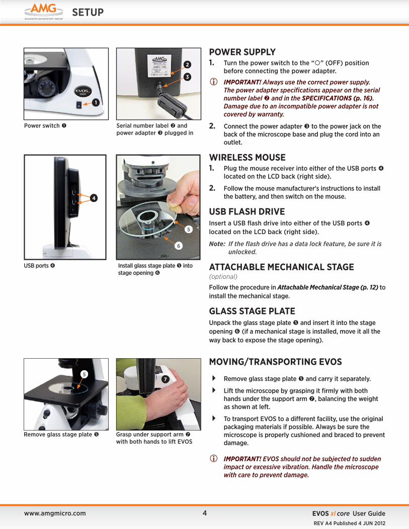
POWER SUPPLY1. Turn the power switch to the “” (OFF) position
before connecting the power adapter.
IMPORTANT! Always use the correct power supply. The power adapter specifications appear on the serial number label and in the SPECIFICATIONS (p. 16). Damage due to an incompatible power adapter is not covered by warranty.
2. Connect the power adapter to the power jack on the back of the microscope base and plug the cord into an outlet.
WIRELESS MOUSE1. Plug the mouse receiver into either of the USB ports
located on the LCD back (right side).
2. Follow the mouse manufacturer's instructions to install the battery, and then switch on the mouse.
USB FLASH DRIVE Insert a USB flash drive into either of the USB ports located on the LCD back (right side).
Note: If the flash drive has a data lock feature, be sure it is unlocked.
ATTACHABLE MECHANICAL STAGE(optional)
Follow the procedure in Attachable Mechanical Stage (p. 12) to install the mechanical stage.
GLASS STAGE PLATEUnpack the glass stage plate and insert it into the stage opening (if a mechanical stage is installed, move it all the way back to expose the stage opening).
Serial number label and power adapter plugged in
Power switch
1
3
MOVING/TRANSPORTING EVOS
� Remove glass stage plate and carry it separately.
� Lift the microscope by grasping it firmly with both hands under the support arm , balancing the weight as shown at left.
� To transport EVOS to a different facility, use the original packaging materials if possible. Always be sure the microscope is properly cushioned and braced to prevent damage.
IMPORTANT! EVOS should not be subjected to sudden impact or excessive vibration. Handle the microscope with care to prevent damage.
USB ports
4
Install glass stage plate into stage opening
5
6
2

www.amgmicro.com 5 EVOS xl core User GuideREV A4 Published 4 JUN 2012
SETUP
EVOS installed in a cell culture hood (EVOS fl model shown above)
ENGLISH METRIC
DEPTH 16.0 in 40.6 cm
WIDTH 12.5 in 31.8 cm
HEIGHT, TRANSPORT 13.5 in 34.3 cm
HEIGHT, DISPLAY 21.0 in 55.3 cm
LCD tilted back
INSTALLING EVOS IN A CELL CULTURE HOODEVOS’ small footprint, simple power connection, and easily-viewed display make it quick to install and convenient to use in a cell culture hood.
DIMENSIONS
EVOS xl core will fit in cell culture hoods that are at least 18 inches (457 mm) deep. If your cell culture hood is smaller, it may be necessary to turn the EVOS at a slight angle to fit.
INSTALLATIONNote: Refer also to the illustrations on p. 4 for more
details about moving EVOS.
1. Remove the glass stage plate and carry it separately.
2. Switch EVOS off and disconnect the power cord.
3. Tilt the LCD screen back until it is nearly parallel with the tabletop.
4. Lift the microscope by grasping it firmly with both hands on the support arm just behind the condenser.
5. Gently place the microscope on a lab cart and transport it to the cell culture hood.
Note: Verify that the hood sash is raised enough for the microscope to slide underneath (approximately 14.5” or higher).
6. Lift the microscope as before and move it into the hood.
7. Tilt the LCD monitor upright.
8. Replace the glass stage plate, connect the power cord, and switch EVOS on.

www.amgmicro.com 6 EVOS xl core User GuideREV A4 Published 4 JUN 2012
QUICK-REFERENCE DIAGRAMS
11. Stage clip12. Stage Y-axis knob 13. Stage X-axis knob
(mechanical stage)
12
13
11
Mechanical Stage Controls*
* The attachable Mechanical Stage is an optional feature. See Attachable Mechanical Stage (p. 12) for installation and removal instructions.
ONSCREEN CONTROLS
Note: Onscreen controls are only available when a mouse is installed.
1. Illumination slider2. Freeze/Live button3. Save button4. Settings button
Note: Refer to the CONTROLS GLOSSARY (p. 10) for more details about onscreen and manual controls.
12 3 4
MANUAL CONTROLS1. Power switch2. Power input jack3. USB ports4. Objective turret5. Coarse focus knob6. Fine focus knob7. Phase turret8. Illumination wheel9. Freeze button10. Save button
19
10
1
2
65
3
7
7
8
8
4
54
6
Roll over the bottom of screen with the mouse to activate the onscreen controls.
www.amgmicro.com 7 EVOS xl core User GuideREV A4 Published 4 JUN 2012
4
USB ports
OPERATION
continued on next page
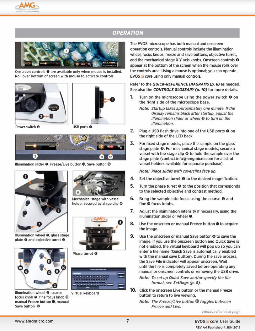
Onscreen controls are available only when mouse is installed. Roll over bottom of screen with mouse to activate controls.
Power switch
2
Illumination slider , Freeze/Live button 11 , Save button 12
3 11 12
Phase turret
BF
8
Illumination wheel , glass stage plate and objective turret
7
5
3
Illumination wheel , coarse focus knob , fine focus knob 10 , manual Freeze button 11 , manual Save button 12
11
10
3
9910
12
Mechanical stage with vessel holder secured by stage clip
6
Virtual keyboard
1
The EVOS microscope has both manual and onscreen operation controls. Manual controls include the illumination wheel, focus knobs, freeze and save buttons, objective turret, and the mechanical stage X-Y axis knobs. Onscreen controls appear at the bottom of the screen when the mouse rolls over the controls area. Using a mouse is optional; you can operate EVOS xl core using only manual controls.
Refer to the QUICK-REFERENCE DIAGRAMS (p. 6) as needed. See also the CONTROLS GLOSSARY (p. 10) for more details.
1. Turn on the microscope using the power switch on the right side of the microscope base. Note: Startup takes approximately one minute. If the
display remains black after startup, adjust the illumination slider or wheel to turn on the illumination.
2. Plug a USB flash drive into one of the USB ports on the right side of the LCD back.
3. For fixed stage models, place the sample on the glass stage plate . For mechanical stage models, secure a vessel with the stage clip to hold the sample over the stage plate (contact [email protected] for a list of vessel holders available for separate purchase).
Note: Place slides with coverslips face up.
4. Set the objective turret to the desired magnification.
5. Turn the phase turret to the position that corresponds to the selected objective and contrast method.
6. Bring the sample into focus using the coarse and fine 10 focus knobs.
7. Adjust the illumination intensity if necessary, using the illumination slider or wheel .
8. Use the onscreen or manual Freeze button 11 to acquire the image.
9. Use the onscreen or manual Save button 12 to save the image. If you use the onscreen button and Quick Save is not enabled, the virtual keyboard will pop up so you can enter a file name (Quick Save is automatically enabled with the manual save button). During the save process, the Save File indicator will appear onscreen. Wait until the file is completely saved before operating any manual or onscreen controls or removing the USB drive.Note: To set up Quick Save and/or specify the file
format, see Settings (p. 8).
10. Click the onscreen Live button or the manual Freeze button to return to live viewing.Note: The Freeze/Live button 11 toggles between
Freeze and Live.

www.amgmicro.com 8 EVOS xl core User GuideREV A4 Published 4 JUN 2012
OPERATION
Operation, continued
1
Settings button and onscreen Save button
Settings popup
SETTINGSThe Settings popup provides various controls to customize display performance and image file names and formats.
The Settings button toggles to display or hide the Settings popup. To save settings, click the Save button in the popup.
Note: If the power is switched off before saving the settings, the system will revert to the most recently saved settings.
IMAGE RESOLUTION/SPEEDThese buttons provide two optimized settings:
� 3MP/Slow produces sharper onscreen images � 1MP/Fast is helpful for quick scanning
CONTRAST & SATURATIONUse the sliders to customize these display attributes. The changes will appear immediately, but they will not be saved unless you click the Save button at the bottom of the popup.
The Set Defaults button will reset contrast and saturation levels to factory settings.
COLOR BALANCE Click the radio buttons to adjust the color balance. Changes will appear immediately, but they will not be saved unless you click the Save button at the bottom of the popup.
IMAGE SAVE FORMAT Click a radio button to select a file format (.tif, .jpg or .bmp).
QUICK SAVE SETTINGSThe Quick Save option allows for a custom base file name; each file name also includes a three-digit sequence number.
When Quick Save is enabled, a single click of the onscreen Save button saves the file under the custom base file name. The manual Save button uses the same base file name.
1. In the Settings menu, click the Edit button under the Quick Save option and enter the base file name in the virtual keyboard.
2. To reset the sequence to zero, click the Reset button .
Note: To prevent the system from overwriting files, Quick Save will use the next available sequence number if the USB installed contains any files with the same base file name.
3. Click the Enabled radio button 11 to enable or disable the Quick Save option.
SOFTWARE UPDATE The Update button 12 is inactive unless a USB drive with an update is installed. See Software Updates (p. 9) for update instructions.
3
8
4
2
5
6
7
9
1011
12

www.amgmicro.com 9 EVOS xl core User GuideREV A4 Published 4 JUN 2012
OPERATION
USB ports
1
Update button
3
Settings button
2
SOFTWARE UPDATESPeriodically, AMG may add functionality and other improvements to the EVOS user interface. We recommend keeping your EVOS microscope up to date with the latest software. If you have any questions about software updates, contact your local distributor. If you do not have your distributor information, you can look it up at the AMG website or contact AMG Customer Service (see p. 15).
DOWNLOAD SOFTWARE UPDATE
Software updates are listed under the Support menu at the AMG website. Alternatively, you can get the latest software and documentation updates from your local EVOS distributor.
1. Download the update and save it to the top level of a USB flash drive with at least 30MB available. Do not open or rename the file on your computer; EVOS will verify and install it during the update process.
2. Download the current user guide for EVOS xl core from the AMG website. The updated user guide covers any changes to software functionality that may have occurred with the update.
INSTALL SOFTWARE UPDATE
1. Plug the USB flash drive into either of the USB ports located on the LCD back (right side).
2. Click the Settings button to display the Settings popup.
3. Click the Update button near the bottom of the Settings popup and follow the onscreen instructions.
IMPORTANT! Do not power off, unplug the USB flash drive, or add/remove any devices during the update.
4. When update is done, reboot the system by powering off and on.
5. Click the About button to confirm you are running the current software version.
4

www.amgmicro.com 10 EVOS xl core User GuideREV A4 Published 4 JUN 2012
CONTROLS GLOSSARY
Note: This section describes all the onscreen and manual controls in detail. To see the most commonly used controls in context, refer to the QUICK-REFERENCE DIAGRAMS (p. 6).
Virtual keyboard
Freeze/Live button
Illumination slider
Settings button
Onscreen clock
Save button
ONSCREEN CONTROLSThis glossary is not alphabetized. Onscreen items are listed from left to right.
ILLUMINATION SLIDER
The illumination slider controls the illumination intensity when the mouse is installed. To turn off illumination, slide all the way to the left.
FREEZE/LIVE BUTTON
The Freeze/Live button toggles between Freeze and Live settings. Click Freeze to capture an image before saving it. Click Live to return to real-time viewing.
SAVE BUTTON
The Save button saves the current frozen image to USB flash drive. The icon is gray when no USB is plugged in. A green USB icon indicates that a flash drive has been inserted. A red USB icon indicates that a save is in progress and the flash drive should not be removed. After the file is saved, the USB icon will turn back to green and the flash drive is safe to remove.
SETTINGS BUTTON
The Settings button displays or hides the Settings popup. See Settings (p. 8) for an itemized explanation of the Settings popup options.
VIRTUAL KEYBOARD
The virtual keyboard popup allows text entry for file names. Click the Accept button when you have finished entering the file name. The Clear button resets the text field.
ONSCREEN CLOCK
The onscreen clock shows date and time and can easily be set. Double click on the time to reveal the settings and simply use the + or – icons to increase or decrease the values. Click Set to save changes.

www.amgmicro.com 11 EVOS xl core User GuideREV A4 Published 4 JUN 2012
CONTROLS GLOSSARY
Power input jack , power switch , USB ports , objective turret
2
3
Phase turret (side and front views) in BF position
9
9
BF
1
back view
8
Illumination wheel , coarse focus knobs , fine focus knobs , coarse focus tension control ring , manual freeze button 10 , manual save button 11
4
6 10
115
6
5
MANUAL CONTROLSThis glossary is not alphabetized. Manual controls are listed in the order they are normally used, with a separate section for the optional Attachable Mechanical Stage (p. 12).
POWER INPUT JACKPlug the power adapter into the power input jack .
POWER SWITCHSet the power switch to “ | ” to turn the microscope on or “O” to turn it off.
USB PORTSPlug the mouse and USB flash drive into the USB ports .
ILLUMINATION WHEELUse the illumination wheel to control illumination intensity.
COARSE & FINE FOCUS KNOBSUse the coarse focus knobs and fine focus knobs to bring the specimen into focus.
COARSE FOCUS TENSION CONTROL RINGTurn the coarse focus tension control ring clockwise (toward the back of the microscope) to tighten the tension. Turn the ring counterclockwise to loosen the tension.
OBJECTIVE TURRETTurn the objective turret to change magnifications. The objective turret clicks into place at each position.
PHASE TURRETSet the phase turret to the position that corresponds with your selected objective for transmitted light observations. The selector will click into place for each of the following positions:
� BF (for brightfield observations)
� 4/10 PH (for phase observations at 4x or 10x)
� 20/40x PH (for phase observations at 20x or 40x)
FREEZE & SAVE BUTTONSUse the Freeze button 10 to capture an image before saving and return to live view after saving. The Save button 11 saves the file with the current settings (Quick Save base file name and selected image format).
MOUSE SCROLL WHEEL (not shown)Unless the cursor is over a popup, the mouse scroll wheel can control illumination intensity. Roll the scroll wheel away from you for more illumination or toward you for less.
7

www.amgmicro.com 12 EVOS xl core User GuideREV A4 Published 4 JUN 2012
CONTROLS GLOSSARY
1
Slide mechanical stage over fixed stage
3
4
1
2
Align screws over holes (bottom view)
2
ATTACHABLE MECHANICAL STAGE (optional)
The mechanical stage is included with the AMEX-1200. You may purchase it separately for use with the AMEX-11OO (contact [email protected] for ordering information).
INSTALLATION/REMOVALFollow this procedure to attach the mechanical stage to the fixed stage. To remove the stage, do the steps in reverse order.
1. Remove the glass stage plate (not shown) and set aside.
2. Tilt the LCD all the way back and gently lay the microscope on its left side.
3. Slide the mechanical stage into position over the right side of the fixed stage .
4. Align the mechanical stage so that the two screws under the mechanical stage align with two holes under the fixed stage .
5. Tighten the left screw by hand first.
6. Use the hex key to tighten the right screw (behind the focus knob). Then fully tighten the left screw with the hex key.
7. Stand the microscope upright.
8. Replace the glass stage plate. See Glass Stage Plate (p. 4) for details.
Tighten right screw with hex key
STAGE CLIPUse the stage clip to secure vessel holders or large samples (i.e. a T-75 flask or multi-well vessel) to the mechanical stage. When properly secured, the sample moves with the stage as you turn the X-axis and Y-axis knobs.
1. Pull the stage clip open and place the vessel holder or sample in the back right corner of the mechanical stage opening. Verify that the edges are straight and the sample is level.
2. Gently release the stage clip.
STAGE Y-AXIS KNOBUse the stage Y-axis knob for front-back movements to position the specimen within the field of view.
STAGE X-AXIS KNOBUse the stage X-axis knob for left-right movements to position the specimen within the field of view.
5
6
Vessel holder secured by stage clip
Stage clip open
7
Y-axis and X-axis knobs
8
9

www.amgmicro.com 13 EVOS xl core User GuideREV A4 Published 4 JUN 2012
GENERAL CARE � When cleaning optical elements, use only optical-grade materials to avoid scratching soft lens coatings.
� Use the appropriate cleaning solutions for each component, as indicated in the Sterilization Procedures below.
� If liquid spills on the microscope, turn off the power immediately and wipe dry.
� Do not exchange objectives between microscopes unless you know that the components have been approved and recommended by AMG.
� After using, cover the microscope with the supplied dust cover.
IMPORTANT! Never disassemble or service the microscope yourself. Unauthorized repairs may damage the microscope or alter its functionality, which may void your warranty. Contact your local EVOS distributor to arrange for service.
OBJECTIVE LENS CAREClean each objective periodically or when necessary with an optical-grade swab and a pre-moistened lens wipe (or lens paper moistened with lens cleaning solution). To avoid scratching the soft lens coatings, use only optical-grade cleaning materials and do not rub the lens. The Objective Lens Cleaning Kit (AMEP-4702) is available for use with all your objective lenses.
Note: To protect all optical components of the microscope, use the dust cover when the microscope is not in use.
STAGE CAREClean the stage surface as needed with paper towels dampened with Kimwipes or 70% ethanol. You may remove the mechanical stage (if installed) for cleaning. Refer to Attachable Mechanical Stage (p. 12) for removal and installation instructions.
STERILIZATION PROCEDURESTo sterilize the EVOS, please follow these procedures:
1. Turn power OFF.
2. Clean the LCD display.
a. Use a soft, dry, lint-free cloth to wipe off any dust from the screen.
b. Clean the LCD display with a non-alcohol based cleaner made for flat-panel displays.
IMPORTANT! Do not spray cleaning fluid directly onto the screen, as it may drip into the display or optics.
3. Lightly wipe EVOS working surfaces (stage top, focus knobs, objective turret, housing) with paper towels or Kimwipes dampened with 70% ethanol or 4,000 ppm hydrogen peroxide (H2O2).
IMPORTANT! Do not allow sterilization solution to get into lubricated areas, such as the stage roller bearings, or any points of rotation such as axles for the stage knobs, condenser wheel, etc. Do not soak any surface in sterilization solution. NEVER spray liquid anywhere on the EVOS. Always wipe surfaces with dampened paper towels instead.
4. If it is necessary to sterilize the condenser, do not apply solution directly to the condenser assembly. Instead, select the desired phase ring, and then cover the condenser with clear plastic wrap and wipe the wrap with sterilization solution.
IMPORTANT! EVOS should not be subjected to UV sterilization. UV degrades many materials, including plastic. Damage from UV exposure is not covered under the manufacturer’s warranty.
CARE & MAINTENANCE

www.amgmicro.com 14 EVOS xl core User GuideREV A4 Published 4 JUN 2012
PROBLEM POSSIBLE SOLUTIONS
Image is too dim, even at brightest setting (particularly at higher magnifications)
�Set the phase turret to the BF position. � If a condenser slider from a different EVOS microscope has been inserted into the condenser, remove the slider. It is not necessary to use sliders with this microscope.
Specks, dots, or blurs on image �Follow the instructions under Objective Lens Care (p. 13) to clean the objectives.
Uneven focus across screen �Position the specimen so that it lies flat on the stage; be sure the specimen’s thickness is even.
Difficulty focusing on coverslipped specimen on standard slide
�Place the slide so the coverslip is facing up (long working-distance objectives require a thick optical substrate, and image best through 1.0 - 1.5 mm of glass or plastic).
LCD screen is black
� If the image is black but the blue LED below the LCD screen is on, adjust the illumination slider or wheel. �Move the objective turret so that light shines through the objective. �Verify that the phase turret on the condenser is not stuck between settings. �Center the specimen over the objective. �Verify the power supply is connected and the power switch is on (the blue LED below the LCD screen indicates that the power is on).
Image does not respond to changes in focus or stage position
�Click the LIVE button to return to real-time observation (note that a red USB icon on the Save button indicates there is an unsaved frozen image, which will be lost unless it is saved before clicking LIVE).
Onscreen Save button does not respond when clicked
� If the USB icon on the Save button appears gray, plug in a USB. If the system does not recognize a USB that is already plugged in, the problem is likely with that particular USB's format, unless the flash drive's data lock is set. Either unlock the flash drive or try using different USB.
Onscreen controls are absent �Follow instructions under Wireless Mouse (p. 4) to Install the wireless USB mouse (AMEP-4713). The onscreen controls are only active when a mouse is installed. �Roll over the bottom of the screen with the mouse to activate the onscreen controls.
Mouse does not work �See solutions listed under MECHANICAL ISSUES, below.
IMAGE ISSUES
TROUBLESHOOTING
MECHANICAL ISSUESPROBLEM POSSIBLE SOLUTIONS
Entire mechanical stage shifts loosely over fixed stage �Tighten screws under stage. See Attachable Mechanical Stage (p. 12).
Vessel does not sit securely when mechanical stage moves
�Use the correct vessel holder for the application (refer to the EVOS Vessel Holders spec sheet, in the documentation USB included with the microscope packaging).
Mouse does not work �Verify the wireless mouse receiver has not been removed from the USB drive. �Check the battery and replace as needed. �Remove any nearby wireless devices that may be interfering with the mouse's signal.
Note: For additional technical support, contact your local EVOS distributor. If you do not have your distributor information, you can look it up at the AMG website or contact AMG Customer Service (see p. 15).

www.amgmicro.com 15 EVOS xl core User GuideREV A4 Published 4 JUN 2012
Thanks for being our valued customer! Advanced Microscopy Group is a Seattle-area (Bothell, WA) optical equipment design and manufacturing firm with a domestic and international client base. Advanced Microscopy Group designs, develops, and manufactures optical systems and software for scientific, biotechnology, industrial and educational fields.
DISCLAIMERThe information in this manual is furnished for informational use only and is subject to change without notice. AMG assumes no responsibility or liability for any errors or inaccuracies that may appear in this document or any software that may be provided in association with this document. No part of this document may be reproduced, stored in a retrieval system, or transmitted in any form or by any means for reasons other than personal use without the express written consent of AMG. Information in this document is provided in connection with AMG products. No license, express or implied, by estoppel or otherwise, to any intellectual property rights is granted by this document.
Toll-free (US & Canada) 866-614-4022 Local 425-368-0444 International 01-425-368-0444 Fax 425-368-0555 E-mail [email protected] Web site www.amgmicro.com
Advanced Microscopy Group Customer Service business hours are 7:00 a.m. – 4:00 p.m. Pacific Standard Time. After hours, you may leave a telephone message. We will return your call the following business day.
ADVANCED MICROSCOPY GROUP22025 20th Ave SESuite 100Bothell, WA 98021
AMG CONTACT INFORMATION
CUSTOMER & TECHNICAL SERVICE
www.amgmicro.com 16 EVOS xl core User GuideREV A4 Published 4 JUN 2012
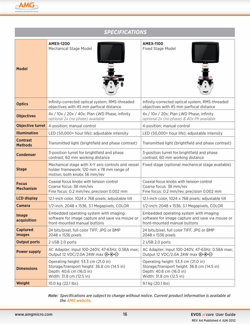
Note: Specifications are subject to change without notice. Current product information is available at the AMG website.
Model
AMEX-1200 Mechanical Stage Model
AMEX-1100 Fixed Stage Model
Optics Infinity-corrected optical system; RMS-threaded objectives with 45 mm parfocal distance
Infinity-corrected optical system; RMS-threaded objectives with 45 mm parfocal distance
Objectives 4x / 10x / 20x / 40x; Plan LWD Phase, infinityoptional 2x (no phase) available
4x / 10x / 20x; Plan LWD Phase, infinity optional 2x (no phase) & 40x Ph available
Objective turret 4-position; manual control 4-position; manual control
Illumination LED (50,000+ hour life); adjustable intensity LED (50,000+ hour life); adjustable intensity
Contrast Methods Transmitted light (brightfield and phase contrast) Transmitted light (brightfield and phase contrast)
Condenser 3-position turret for brightfield and phase contrast; 60 mm working distance
3-position turret for brightfield and phase contrast; 60 mm working distance
StageMechanical stage with X-Y axis controls and vessel holder framework; 120 mm x 78 mm range of motion; both knobs 56 mm/rev
Fixed stage (optional mechanical stage available)
Focus Mechanism
Coaxial focus knobs with tension control Coarse focus: 38 mm/rev Fine focus: 0.2 mm/rev, precision 0.002 mm
Coaxial focus knobs with tension controlCoarse focus: 38 mm/rev Fine focus: 0.2 mm/rev, precision 0.002 mm
LCD display 12.1-inch color, 1024 x 768 pixels; adjustable tilt 12.1-inch color, 1024 x 768 pixels; adjustable tilt
Camera 1/2-inch, 2048 x 1536, 3.1 Megapixels, COLOR 1/2-inch, 2048 x 1536, 3.1 Megapixels, COLOR
Image acquisition
Embedded operating system with imaging software for image capture and save via mouse or front-mounted manual buttons
Embedded operating system with imaging software for image capture and save via mouse or front-mounted manual buttons
Captured images
24 bits/pixel, full color TIFF, JPG or BMP 2048 x 1536 pixels
24 bits/pixel, full color TIFF, JPG or BMP 2048 x 1536 pixels
Output ports 2 USB 2.0 ports 2 USB 2.0 ports
Power supply AC Adapter; Input 100-240V, 47-63Hz; 0.58A max; Output 12 VDC/2.0A 24W max
AC Adapter; Input 100-240V, 47-63Hz; 0.58A max; Output 12 VDC/2.0A 24W max
Dimensions
Operating height: 53.3 cm (21.0 in)Storage/transport height: 36.8 cm (14.5 in)Depth: 40.6 cm (16.0 in)Width: 31.8 cm (12.5 in)
Operating height: 53.3 cm (21.0 in)Storage/transport height: 36.8 cm (14.5 in)Depth: 40.6 cm (16.0 in)Width: 31.8 cm (12.5 in)
Weight 10.0 kg (22.1 lbs) 9.1 kg (20.1 lbs)
SPECIFICATIONS

amgmicro.com | [email protected] | 866-614-4022 (01-425-368-0444 outside the U.S.)www.amgmicro.com | [email protected] | 866-614-4022 (01-425-368-0444 outside the US)