USE OF THE OSCILLOSCOPE Modified from a presentation written by David Matzke by: Donald Wisniewski,...
47
USE OF THE OSCILLOSCOPE USE OF THE OSCILLOSCOPE Modified from a presentation written by David Matzke by: Donald Wisniewski, Dawn Wisniewski, Huzefa Mamoola and Angela Nolte Under the direction of: Dr. Ruth Dusenbery and Dr. Paul Zitzewitz With funds from the Office of the Provost, UM-D, and NSF CCLI grant DUE#9952827 to RD and PZ. Science Learning Center Science Learning Center University of Michigan – University of Michigan – Dearborn Dearborn
-
date post
22-Dec-2015 -
Category
Documents
-
view
221 -
download
0
Transcript of USE OF THE OSCILLOSCOPE Modified from a presentation written by David Matzke by: Donald Wisniewski,...
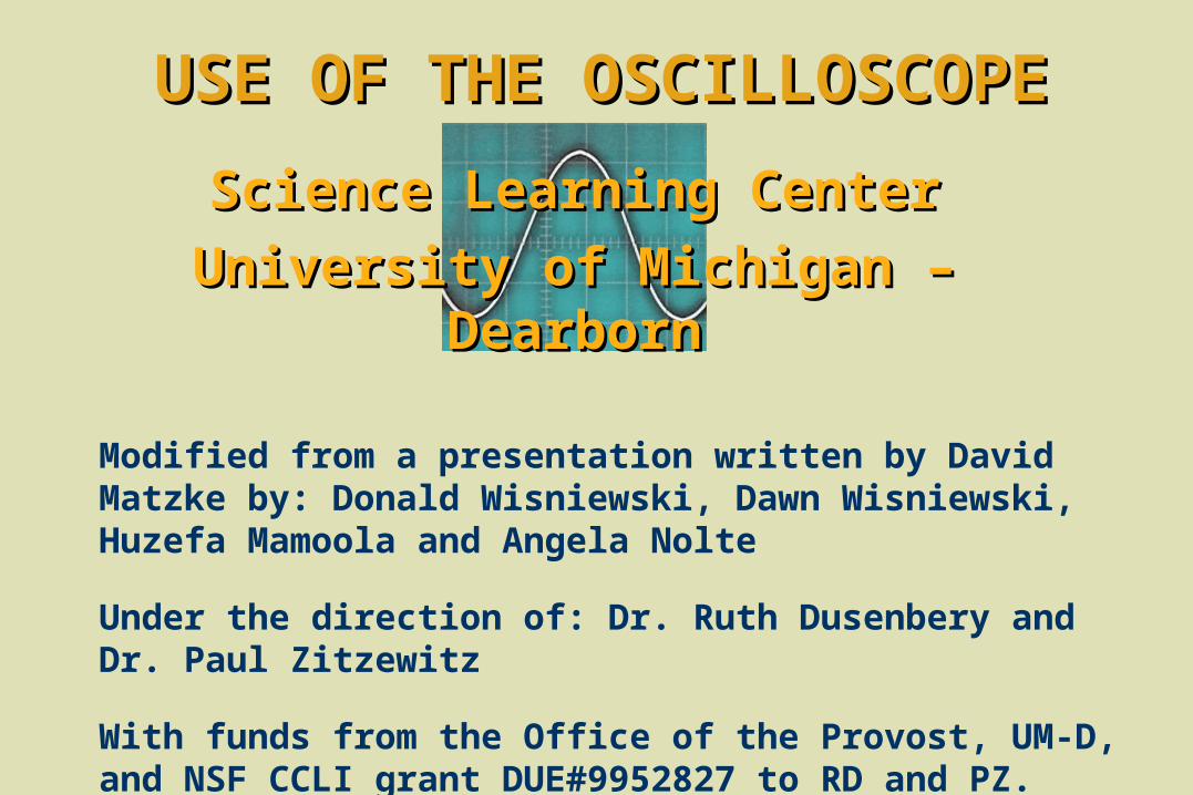
USE OF THE OSCILLOSCOPEUSE OF THE OSCILLOSCOPE
Modified from a presentation written by David Matzke by: Donald Wisniewski, Dawn Wisniewski, Huzefa Mamoola and Angela Nolte
Under the direction of: Dr. Ruth Dusenbery and Dr. Paul Zitzewitz
With funds from the Office of the Provost, UM-D, and NSF CCLI grant DUE#9952827 to RD and PZ.
Science Learning CenterScience Learning Center
University of Michigan – University of Michigan – DearbornDearborn

OBJECTIVES
In this module you will learn how use an oscilloscope to:
measure direct current (D.C.) voltage and
measure alternating current (A.C.) voltage.
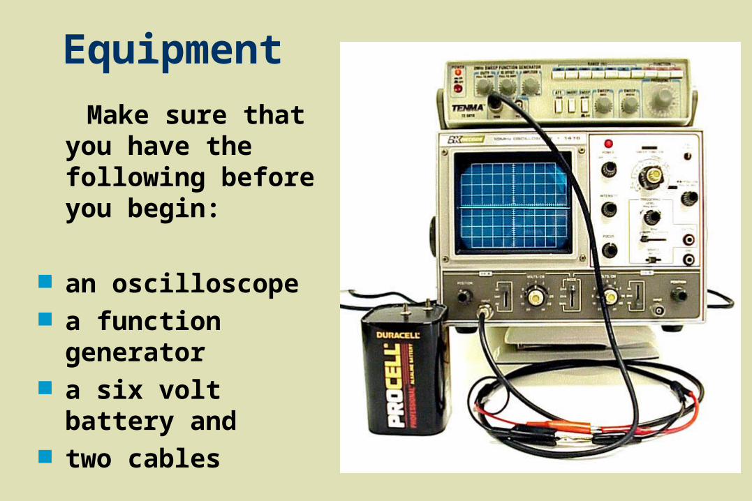
Equipment
Make sure that you have the following before you begin:
an oscilloscope a function generator a six volt battery and two cables
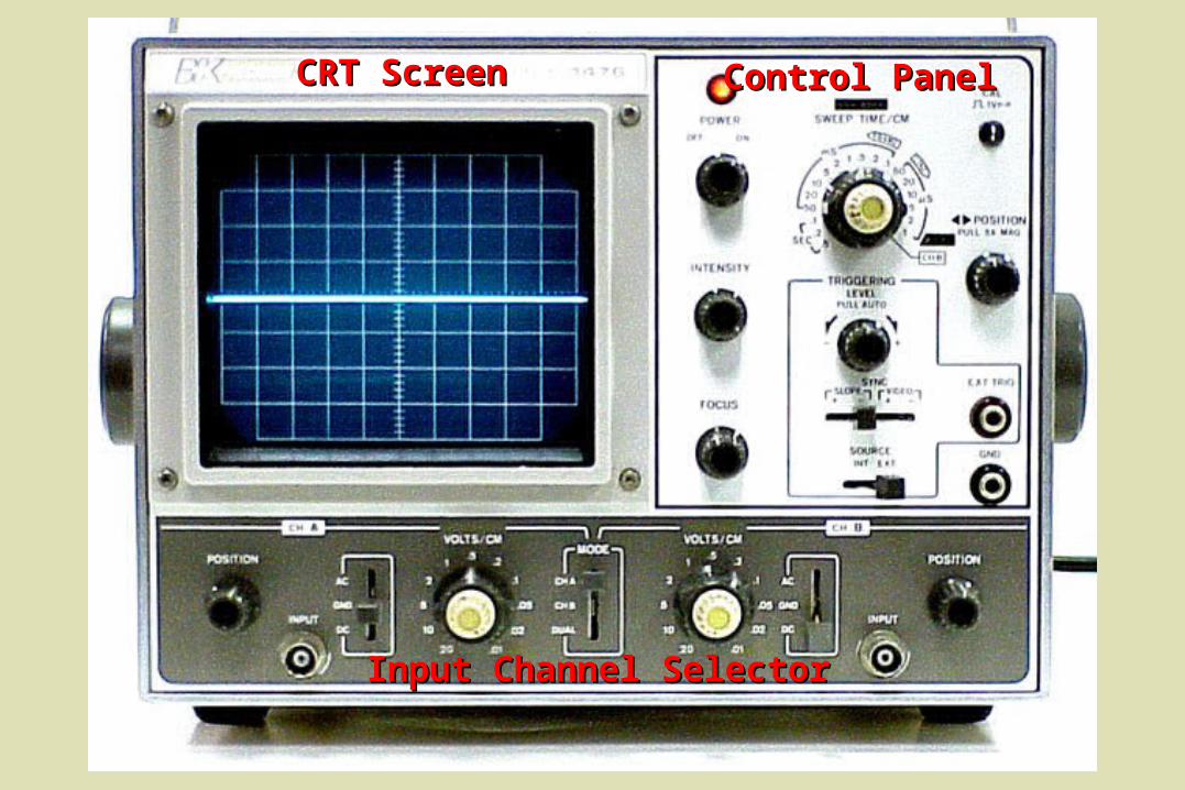
Input Channel SelectorInput Channel Selector
Control PanelControl PanelCRT ScreenCRT Screen
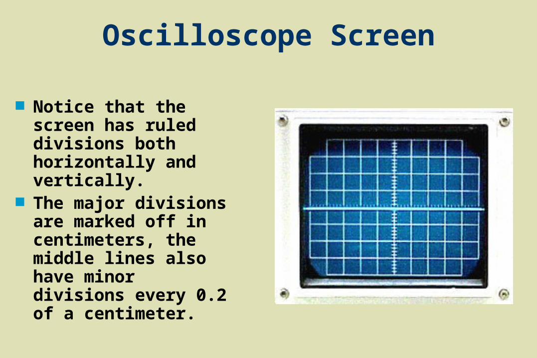
Oscilloscope Screen
Notice that the screen has ruled divisions both horizontally and vertically.
The major divisions are marked off in centimeters, the middle lines also have minor divisions every 0.2 of a centimeter.
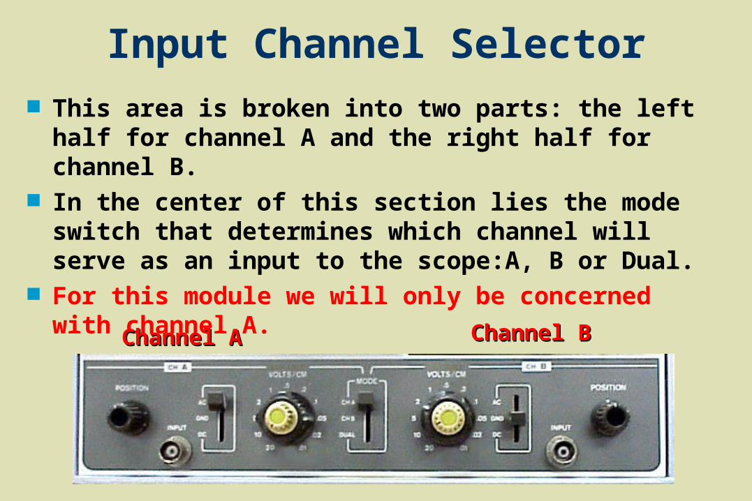
Input Channel Selector This area is broken into two parts: the left half for
channel A and the right half for channel B. In the center of this section lies the mode switch
that determines which channel will serve as an input to the scope:A, B or Dual.
For this module we will only be concerned with channel A.
Channel AChannel A Channel BChannel B
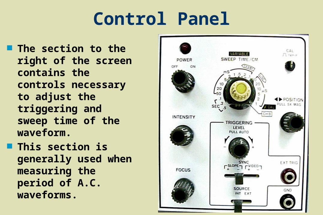
Control Panel
The section to the right of the screen contains the controls necessary to adjust the triggering and sweep time of the waveform.
This section is generally used when measuring the period of A.C. waveforms.
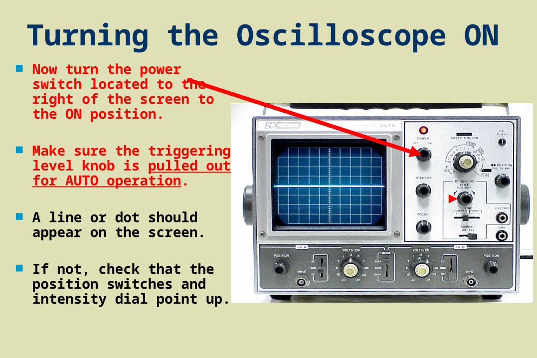
Turning the Oscilloscope ON Now turn the power switch
located to the right of the screen to the ON position.
Make sure the triggering level knob is pulled out for AUTO operation.
A line or dot should appear on the screen.
If not, check that the position switches and intensity dial point up.
Set Mode Switch
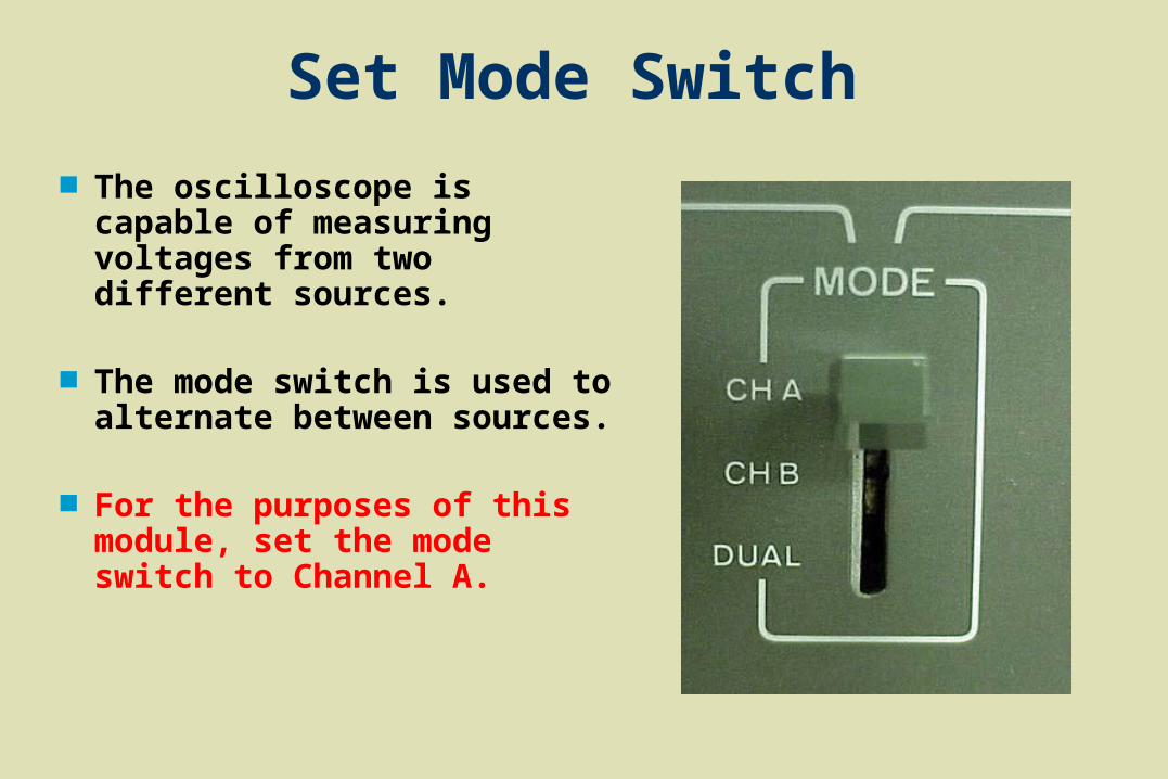
The oscilloscope is capable of measuring voltages from two different sources.
The mode switch is used to alternate between sources.
For the purposes of this module, set the mode switch to Channel A.
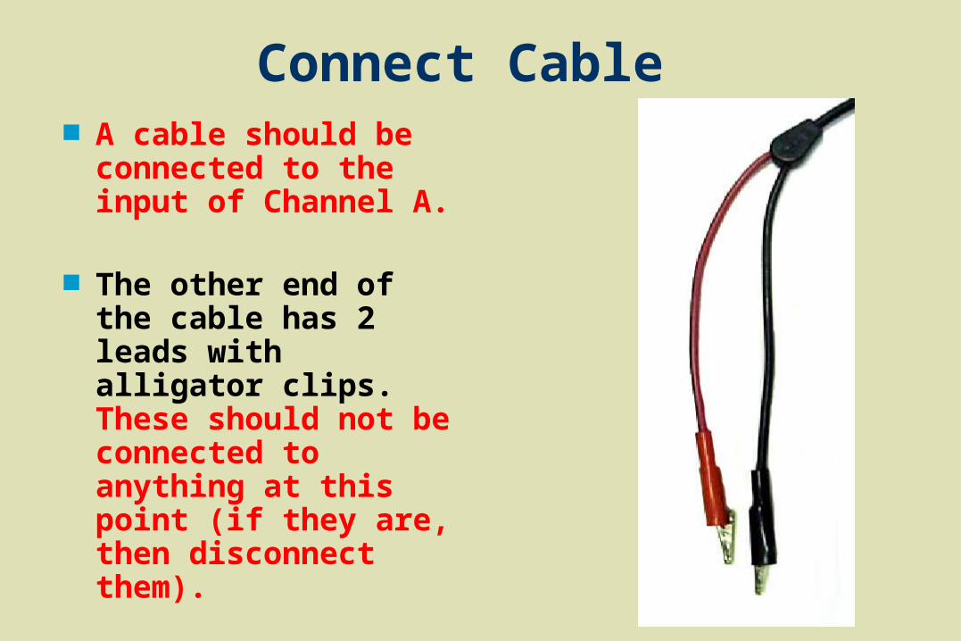
Connect Cable A cable should be
connected to the input of Channel A.
The other end of the cable has 2 leads with alligator clips. These should not be connected to anything at this point (if they are, then disconnect them).
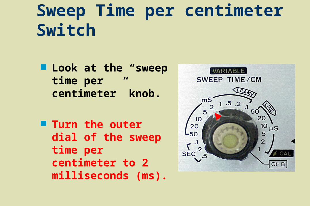
Sweep Time per centimeter Switch
Look at the “sweep time per centimeter” knob.
Turn the outer dial of the sweep time per centimeter to 2 milliseconds (ms).
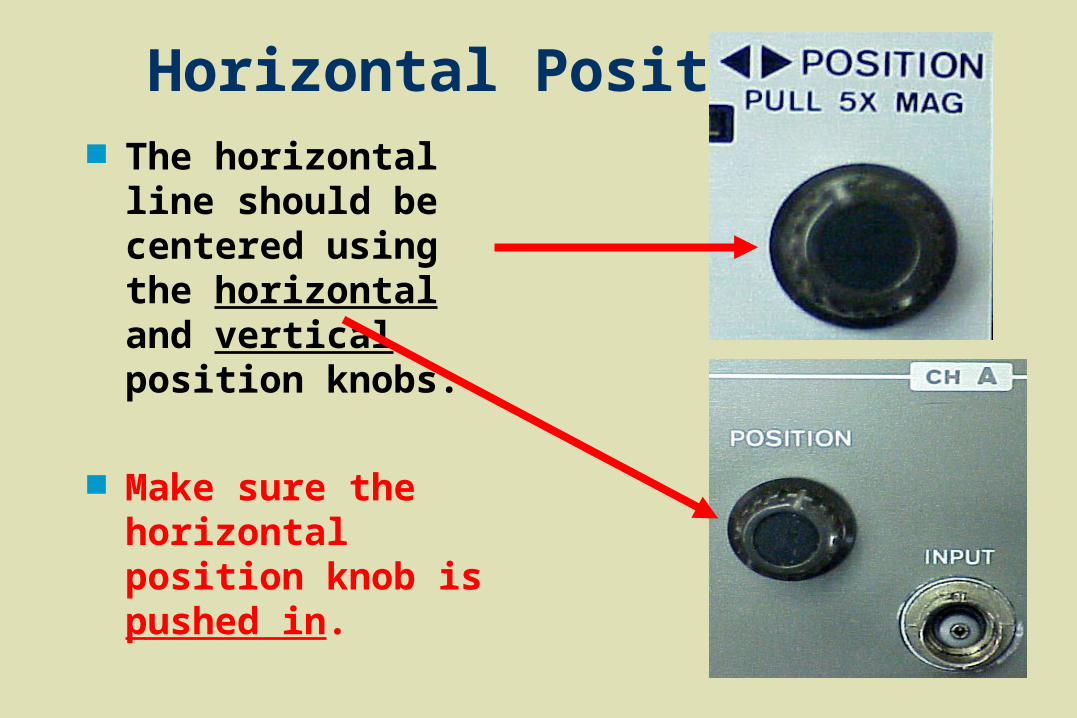
Horizontal Position The horizontal line
should be centered using the horizontal and vertical position knobs.
Make sure the horizontal position knob is pushed in.

Intensity and Focus Dials
The intensity dial controls the brightness of the line.
The focus dial controls the sharpness of the line.

Summary Measuring DC VoltageTo get started you should follow these steps: Set mode to channel A. Connect cable to input. Leads should be free. Turn power ON and wait for dot or line to appear. Pull Triggering level knob out. Adjust intensity and focus as needed. Set sweep time /sec knob till the line on the screen
is seen clear and steady. Adjust horizontal and vertical position knob to
make sure that the line is fully visible.

Measuring a Direct Current Voltage
Switch the A.C.-GND-D.C. switch to the D.C. position.
Set the volts/cm dial on 1.
Turn the beige dial clockwise all the way to put the volts/cm dial in the “calibrated” position.
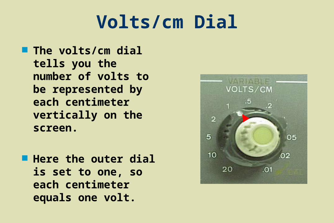
Volts/cm Dial The volts/cm dial tells
you the number of volts to be represented by each centimeter vertically on the screen.
Here the outer dial is
set to one, so each centimeter equals one volt.

Checking Oscilloscope Calibration
Use the vertical position dial to move the baseline near the bottom of the screen.
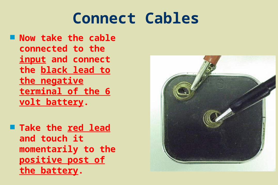
Connect Cables Now take the cable
connected to the input and connect the black lead to the negative terminal of the 6 volt battery.
Take the red lead and touch it momentarily to the positive post of the battery.
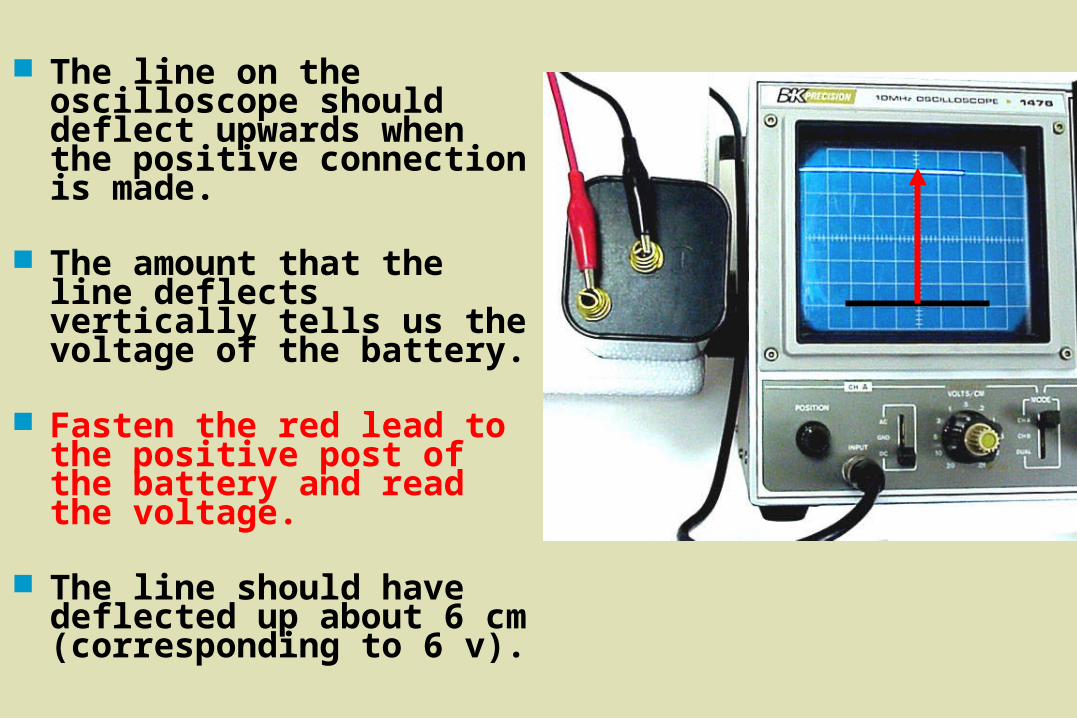
The line on the oscilloscope should deflect upwards when the positive connection is made.
The amount that the line deflects vertically tells us the voltage of the battery.
Fasten the red lead to the positive post of the battery and read the voltage.
The line should have deflected up about 6 cm (corresponding to 6 v).
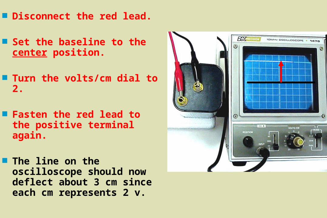
Disconnect the red lead.
Set the baseline to the center position.
Turn the volts/cm dial to 2.
Fasten the red lead to the positive terminal again.
The line on the oscilloscope should now deflect about 3 cm since each cm represents 2 v.
Notice that the volts/cm dial does not change the voltage.
It is a sensitivity dial that allows us to measure a wide range of voltages by telling us how much voltage is represented by each centimeter along the Y-axis.
Disconnect the battery from the leads on the input cables.
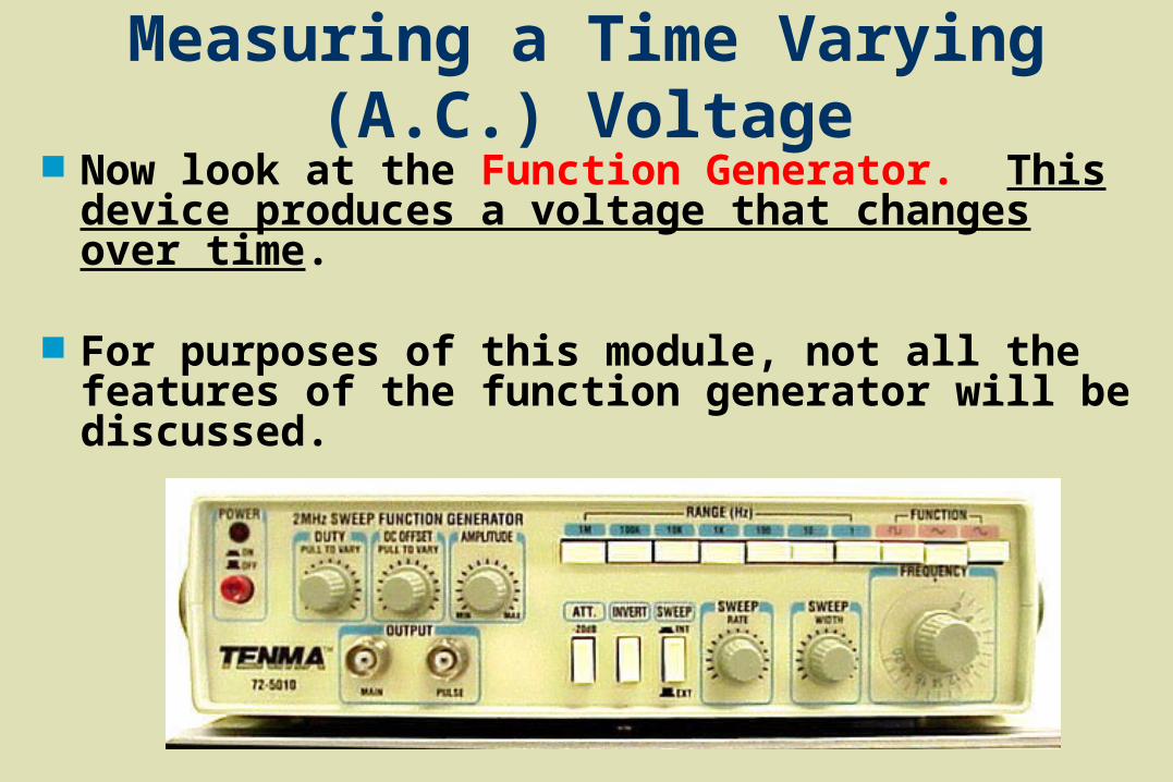
Measuring a Time Varying (A.C.) Voltage Now look at the Function Generator. This
device produces a voltage that changes over time.
For purposes of this module, not all the features of the function generator will be discussed.
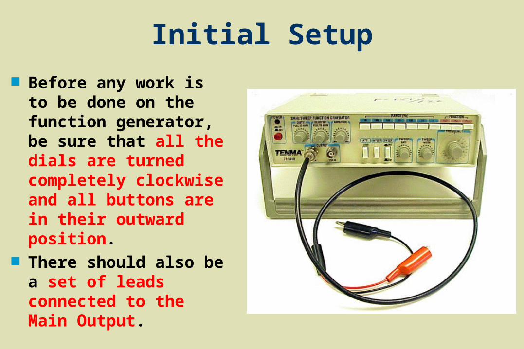
Initial Setup
Before any work is to be done on the function generator, be sure that all the dials are turned completely clockwise and all buttons are in their outward position.
There should also be a set of leads connected to the Main Output.
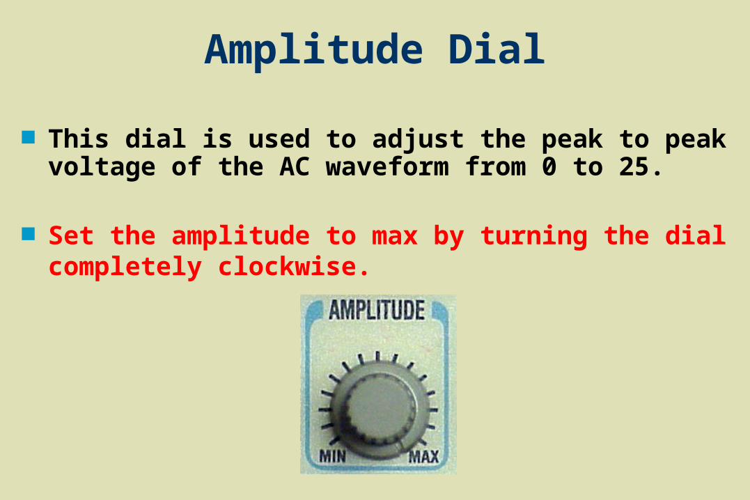
Amplitude Dial
This dial is used to adjust the peak to peak voltage of the AC waveform from 0 to 25.
Set the amplitude to max by turning the dial completely clockwise.
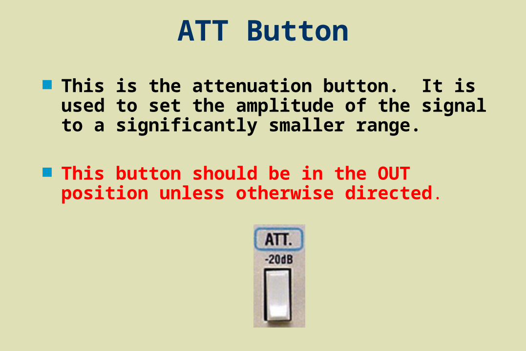
ATT Button
This is the attenuation button. It is used to set the amplitude of the signal to a significantly smaller range.
This button should be in the OUT position unless otherwise directed.
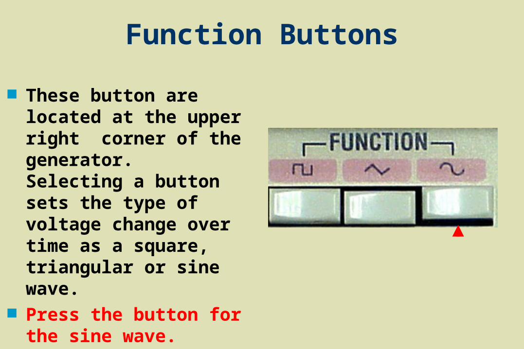
Function Buttons
These button are located at the upper right corner of the generator. Selecting a button sets the type of voltage change over time as a square, triangular or sine wave.
Press the button for the sine wave.
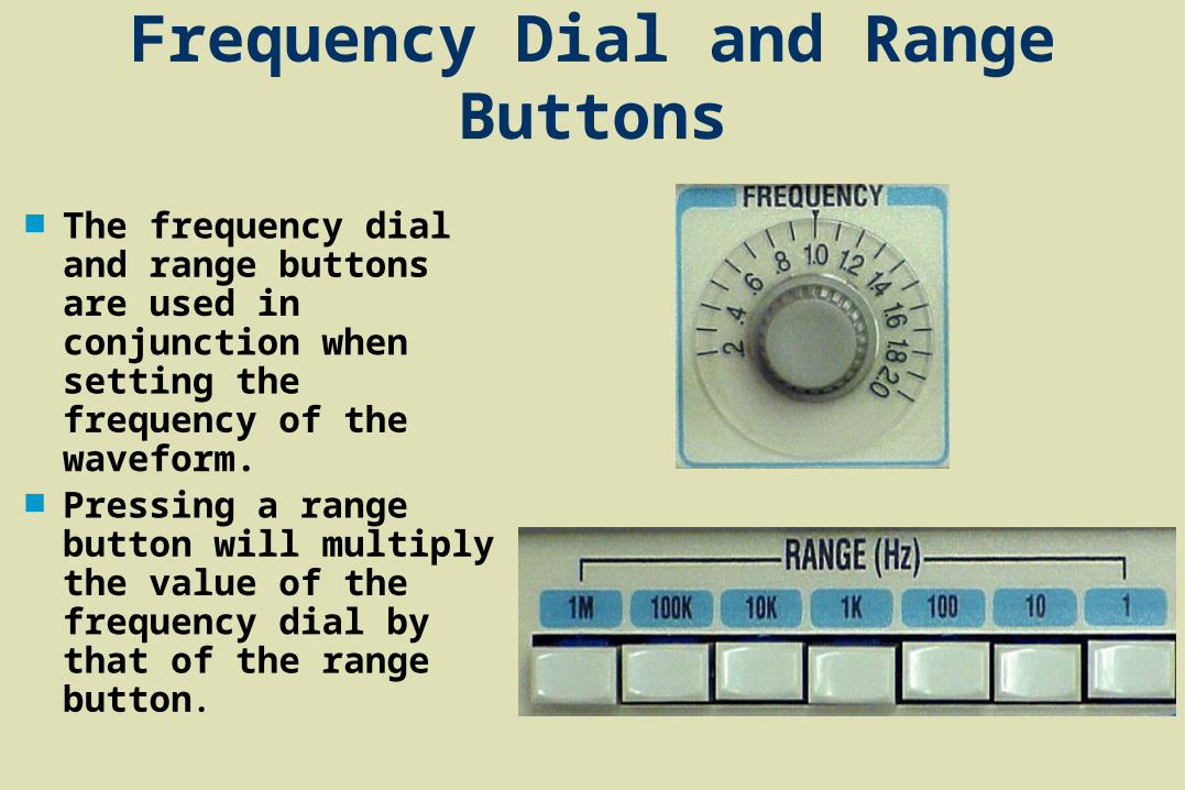
Frequency Dial and Range Buttons
The frequency dial and range buttons are used in conjunction when setting the frequency of the waveform.
Pressing a range button will multiply the value of the frequency dial by that of the range button.
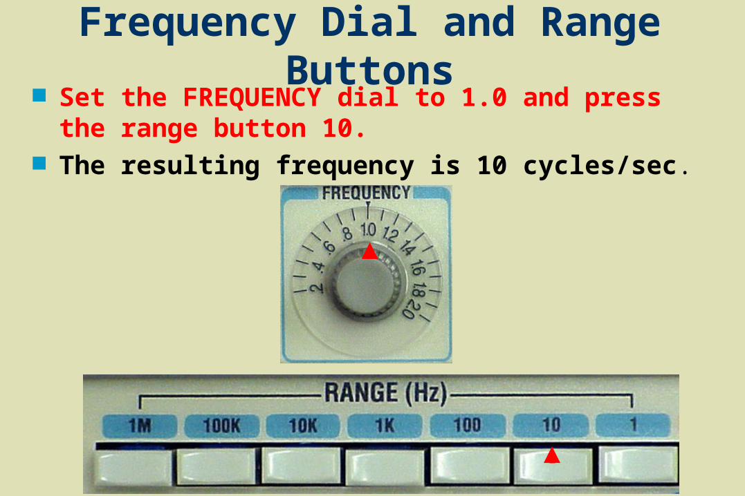
Frequency Dial and Range Buttons Set the FREQUENCY dial to 1.0 and press the range
button 10. The resulting frequency is 10 cycles/sec.
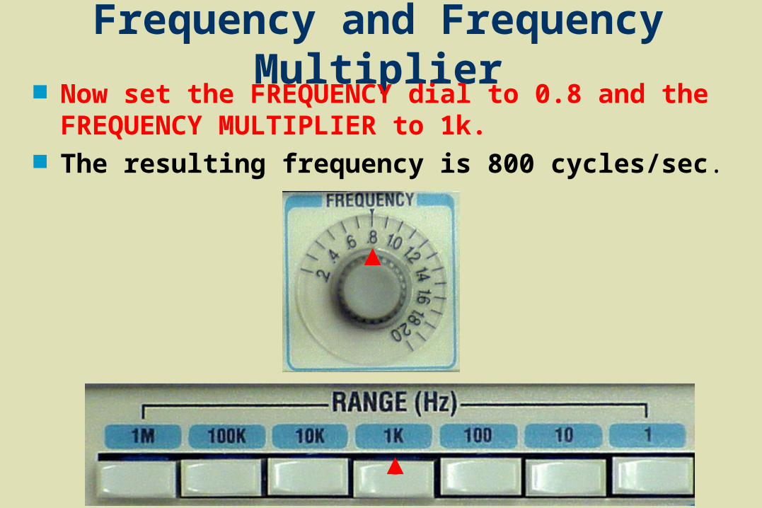
Frequency and Frequency Multiplier Now set the FREQUENCY dial to 0.8 and the
FREQUENCY MULTIPLIER to 1k. The resulting frequency is 800 cycles/sec.

Connecting the Function Generator to the Oscilloscope
Connect the alligator clip of the black lead from the function generator to the alligator clip of the black lead from the oscilloscope.
Do the same with the red leads.
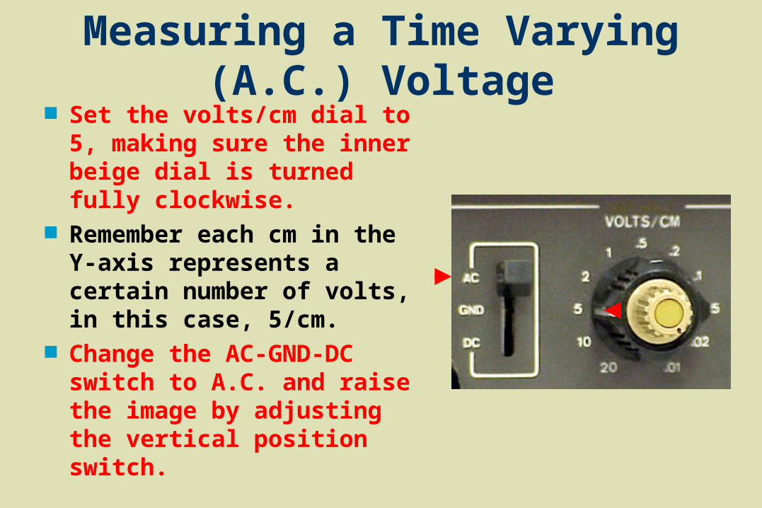
Measuring a Time Varying (A.C.) Voltage Set the volts/cm dial to 5,
making sure the inner beige dial is turned fully clockwise.
Remember each cm in the Y-axis represents a certain number of volts, in this case, 5/cm.
Change the AC-GND-DC switch to A.C. and raise the image by adjusting the vertical position switch.
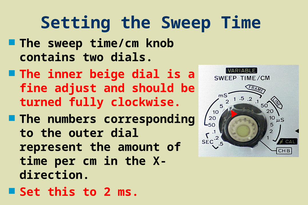
Setting the Sweep Time The sweep time/cm knob
contains two dials. The inner beige dial is a fine
adjust and should be turned fully clockwise.
The numbers corresponding to the outer dial represent the amount of time per cm in the X-direction.
Set this to 2 ms.
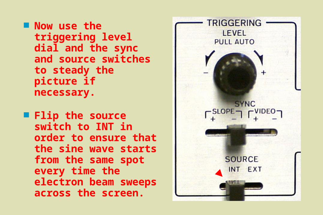
Now use the triggering level dial and the sync and source switches to steady the picture if necessary.
Flip the source switch to INT in order to ensure that the sine wave starts from the same spot every time the electron beam sweeps across the screen.
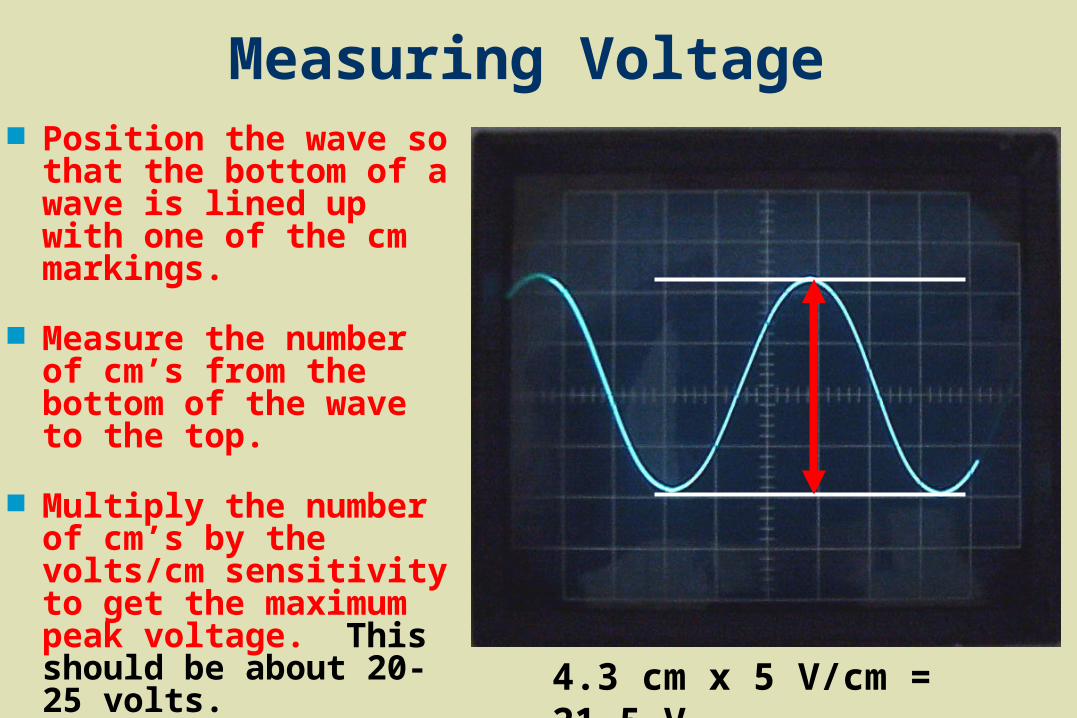
Position the wave so that the bottom of a wave is lined up with one of the cm markings.
Measure the number of cm’s from the bottom of the wave to the top.
Multiply the number of cm’s by the volts/cm sensitivity to get the maximum peak voltage. This should be about 20-25 volts. 4.3 cm x 5 V/cm = 21.5 V
Measuring Voltage
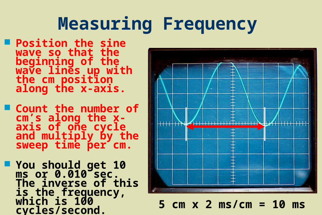
Measuring Frequency Position the sine wave
so that the beginning of the wave lines up with the cm position along the x-axis.
Count the number of cm’s along the x-axis of one cycle and multiply by the sweep time per cm.
You should get 10 ms or 0.010 sec. The inverse of this is the frequency, which is 100 cycles/second.
5 cm x 2 ms/cm = 10 ms
Changing the Oscilloscope Settings
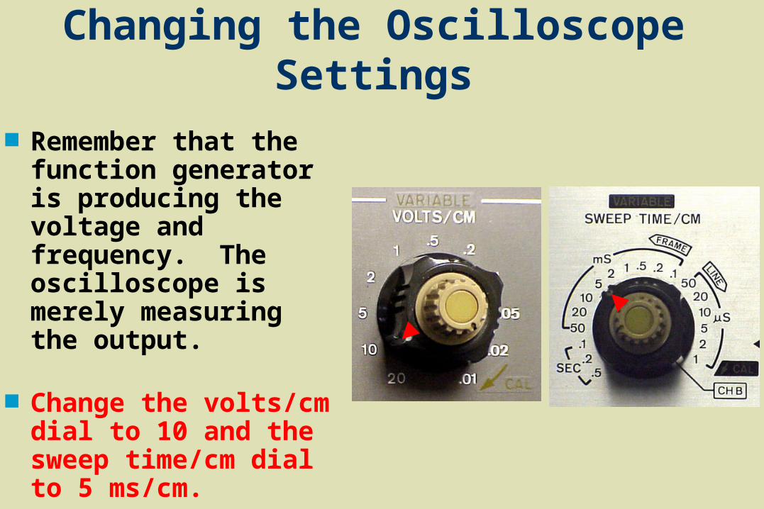
Remember that the function generator is producing the voltage and frequency. The oscilloscope is merely measuring the output.
Change the volts/cm dial to 10 and the sweep time/cm dial to 5 ms/cm.

Changing the Oscilloscope Settings.
Watch the wave form change as you change the volts/cm dial to 10 and the sweep time/cm dial to 5 ms/cm.
Adjust the triggering level knob if necessary to get a stable image.
You should still be reading 20-25 V and 100 cycles/sec.
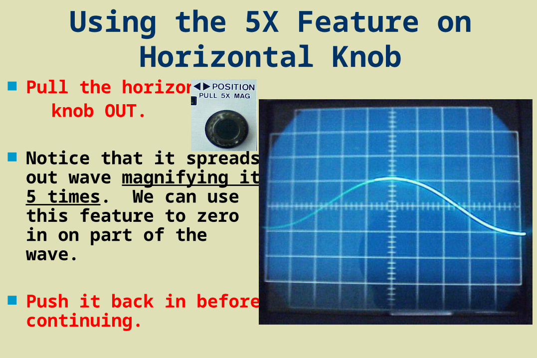
Using the 5X Feature on Horizontal Knob
Pull the horizontal knob OUT.
Notice that it spreads out wave magnifying it 5 times. We can use this feature to zero in on part of the wave.
Push it back in before continuing.
Changing Function Generator Settings Now change the AMPLITUDE dial on the
function generator.
Notice that the reading on the oscilloscope changes.
Dial in a different frequency.
Remember that this changes the time for one wave on the oscilloscope.
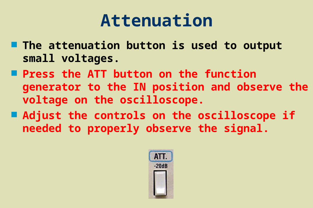
Attenuation The attenuation button is used to output small
voltages. Press the ATT button on the function generator to the
IN position and observe the voltage on the oscilloscope.
Adjust the controls on the oscilloscope if needed to properly observe the signal.
Turn on the function generator by pressing in the power button.
Turn all dials completely clockwise and ensure all buttons are in the outward position.
Press the function button of the desired wave function, i.e., triangle, square, or sine wave.
Set the frequency dial and the press the range button of the function generator to achieve the desired frequency.
Connect the leads of the function generator’s output to the leads of the oscilloscope’s input; red lead to red lead and black lead to black lead.
Summary Measuring AC Voltage
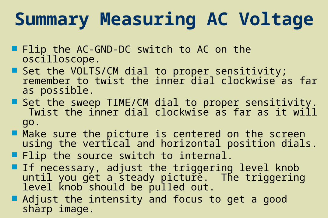
Flip the AC-GND-DC switch to AC on the oscilloscope. Set the VOLTS/CM dial to proper sensitivity; remember to
twist the inner dial clockwise as far as possible. Set the sweep TIME/CM dial to proper sensitivity. Twist
the inner dial clockwise as far as it will go. Make sure the picture is centered on the screen using the
vertical and horizontal position dials. Flip the source switch to internal. If necessary, adjust the triggering level knob until you get
a steady picture. The triggering level knob should be pulled out.
Adjust the intensity and focus to get a good sharp image.
Summary Measuring AC Voltage

Practice Problem #1
Set frequency to 100 Hz. Set attenuation to 10. Find the peak to peak voltage and Find the time period for one cycle.

Answer to #1
Peak to peak voltage = 7 volts The time or period = 1 ms.

Practice Problem #2
Set frequency to 50 Hz. Set attenuation to 30. Find the peak to peak voltage and Find the time or period for one cycle.
Answer to #2
Peak to peak voltage = 0.7 volts Time or period = 20 ms.

You have now completed the Oscilloscope Module.
Obtain a Post Test and make measurements using the assigned
Function Generator settings