TRIGA REACTOR CHARACTERISTICS*ansn.bapeten.go.id/files/Chapter1_TRIGA_Reactor_Characteristics.pdf4...
25
TRIGA REACTOR CHARACTERISTICS*
Transcript of TRIGA REACTOR CHARACTERISTICS*ansn.bapeten.go.id/files/Chapter1_TRIGA_Reactor_Characteristics.pdf4...

TRIGA REACTOR CHARACTERISTICS*

2
Overview This module describes the general design, characteristics and parameters of TRIGA reactors and fuel. Much of this information should be incorporated into any reactor operator training program and, in many cases, the facility Safety Analysis Report. Learning Objectives
1. You should understand the basics of the physics and mechanical design of the TRIGA fuel.
2. You should understand the unique operational characteristics of the TRIGA fuel
and realize the differences between TRIGA fuels and other, more traditional reactor fuels

3
CONTENTS Page Overview 2 1. TRIGA reactor parameters and characteristics 4 1.1 History of TRIGA reactors 4 1.2 Critical mass of the TRIGA reactor Vienna 4 1.3 Calculated power per FLIP element 6 1.4 Loss of coolant accident (FLIP) 7 1.5 Design basis accident 8 1.6 TRIGA reactor moderation 8 1.7 Moderating properties of zirconium hydride 9 1.8 Prompt negative temperature coefficient of reactivity 10 1.9 Temperature coefficients of standard 20% enriched fuel 11 1.9.1 Cell and non-homogeneous effects 11 1.9.2 Doppler broadening effects 12 1.9.3 Core leakage effects 12 1.10 Temperature coefficients of 70% Enriched Fuel 14 1.11 Pool temperature coefficient of reactivity 17 1.12 Void coefficient of reactivity 17 1.13 Fuel element reactivity worths 17 1.14 Power coefficient of reactivity 18 1.15 Reactor nuclear parameters 18 1.16 TRIGA pulsing performance 19 1.17 The Fuchs-Nordheim model and pulsing characteristics 20 1.18 Estimating peak power of TRIGA pulses 22 1.19 Reactivity accident 23 1.20 TRIGA safety compared with other systems 23 1.20.1 Summary 23 1.20.2 Review of reactor safety tests 23 Listing of Figures and Tables 25

4
1. TRIGA REACTOR PARAMETERS AND CHARACTERISTICS 1.1 History of TRIGA reactors In the early 1950ies, the U.S. company General Atomics (GA) located in San Diego, California, developed a small research reactor which • would be inherently safe • is operationally flexible and relatively inexpensive • allowed a large variety of experiments • used low enriched uranium. At the First Geneva Conference on Peaceful Uses of Atomic Energy in 1955, the first TRIGA-type reactor (Training, Research, Isotope Production General Atomic) was presented to the public. During the following decades, approximately 60 TRIGA reactors were constructed all over the world. Three basic TRIGA models have been produced: • Mark-I: underground pool without beam tubes • Mark-II: above ground tank with several beam tubes • Mark-III: above ground oval tank with movable core. A short description of the three TRIGA reactor types and a list of all worldwide TRIGA reactors that were put into operation (some of them already decommissioned) is given in Appendix 1. 1.2 Critical mass of the TRIGA reactor Criticality of a typical TRIGA Mark II reactor is usually achieved with about 57 standard (low enriched, < 20%) TRIGA fuel elements (about 2 kg 235U). To allow higher power operation (>100 kW), more fuel elements and several graphite reflector elements are added in the outer rings of the core grid plate. The added fuel produces a core excess reactivity which may be limited to about 2 $ depending on the specific license of the reactor. A typical core loading diagram of a circular grid reactor is shown in Figure 1. More recent TRIGA core designs will use a hexagonal, rather than a circular, design for better thermal and hydraulic characteristics. Uranium-235 is consumed during operation of any reactor, the amount or burnup-rate depends on the reactor power. For a typical 250 kW TRIGA reactor operating for about 200 days a year, 8 hours per day the U-235 consumption is approximately 20 grams per year. Standard reactor physics calculations show that for 1 MWd (or 24000kWh) of thermal power production 1,25 grams of U-235 are consumed for most reactors. Experience has shown that for a well used 250 kW TRIGA reactor, approximately one fuel element has to be added every second year to compensate for the reactivity loss by fuel burnup across the core; therefore, for 40 years of operation, approximately 20 fuel elements have to be added. More fuel may be required to compensate for the reactivity caused by the insertion of large experiments. Since the development of the original TRIGA type reactors in the mid-fifties, new types of TRIGA fuel elements have been developed. A significant change was replacing (in the design) the aluminium cladding material to stainless steel (SST). Therefore, many TRIGA reactors may be operated with a mixed core with different types of fuel elements in the core.
5
Figure 1: Standard core of a TRIGA Among the SST elements several different types of fuel exist. Those most often seen in reactors today are produced with <20% enrichment (Standard SST) and those with approximately 70% enrichment (called FLIP = Fuel Lifetime Improvement Program). Details about these different fuel types are given in Table 1. Relatively recently, General Atomics has designed and certified a new low enriched fuel with high uranium loading (as high as 30 wt-%) to replace the FLIP fuel. Gradually, FLIP research reactors will convert to low enriched uranium (LEU) fuel due to worldwide nuclear proliferation concerns. This new LEU fuel has higher uranium loading to give a long fuel lifetime without high enrichment. Additionally, General Atomics has produced a TRIGA fuel with a smaller diameter for higher power (>3MW) operations.

6
The neutron reflector materials around the core and the absence or presence of graphite reflector elements in empty fuel positions also affect the reactor critical mass rather strongly. Replacing the graphite with a water reflector on a TRIGA Mark II raises the critical mass (more fuel needed) by about 25%. Adding a ring of graphite reflector elements in the G-ring (the outer ring of the grid plate) around a water-reflected core cut will reduce the amount of fuel needed for criticality by about 10%.
Fuel element type 102 104 110 (FLIP) Fuel moderator
material U-ZrH1.0 U-ZrH1.65 U-ZrH1,65
Uranium content (wt%) 8.5 8.5 8.5
Enrichment (%) 20 20 70 Average 235U content
(g) 38 38 136
Burnable poison SmO3-disk none Erbium 1.6 wt% Diameter of fuel
meat 35.8 mm 36.3 mm 36.3 mm
Length of fuel meat 35.6 mm 38.1 mm 38.1 mm Graphite reflector
length 10.2 mm 8.73 mm 8.81 mm
Cladding material Al-1100F 304 SS 304 SS Cladding thickness 0.76 mm 0.51 mm 0.51 mm
Table 1: Principal fuel element design parameters
1.3 Calculated power per FLIP (=Fuel Lifetime Improvement Program) element Power density is a significant parameter and reactor operators should be acquainted with the TRIGA values. Generally, operators should try to maintain the reactor flux as flat or constant as possible across the reactor by judiciously loading new elements in the outer ring and gradually moving them towards the center as the fuel is burned. Standard reactor physics calculations show that the neutron flux and local reactor power is peaked towards the center of the TRIGA core. The calculated results for a FLIP reactor are listed in Table 2. Power densities in the higher enriched fuels such as FLIP are slightly higher but the values are very close to a standard fuelled reactor of similar power level. Note that the highest power density occurs in the central B ring, as expected. The effect of the graphite elements in the outer ring is to slightly increase the power density in the outer fuelled rings and to slightly reduce the power density in the inner fuelled rings, thus flattening the neutron flux across the core.
Average power per element (kW/element) at total core power for a 1000 kW TRIGA
B ring C ring D ring E ring F ring 18.85 14.68 12.63 9.99 9.22
Table 2: Calculated power per element (FLIP)

7
Table 3 lists the maximum, minimum, and the average power per element, along with ratios of the maximum-to-minimum power and the maximum-to-average power per element. Again, these values are calculated for a FLIP core but may be used as approximations for other TRIGA reactors. Each facility’s Safety Analysis Report (SAR) should have values calculated specifically for the facility.
Table 3: Calculated maximum, minimum and average power per element (FLIP)
1.4 Loss of Coolant Accident (LOCA) If the reactor pool is accidentally drained of water, the fission product decay heat will be removed primarily by natural convection in air. If the decay heat production is sufficiently low or the time interval between reactor shutdown and the core uncover is long enough, the convective cooling by air will be sufficient to maintain the fuel at a temperature which will not damage the fuel elements. This accident was analysed with the following results: a) It has been demonstrated that standard fuel suspended in air can tolerate temperatures as
high as 900 ºC without damage to the clad. For FLIP fuel, this value is 938 ºC. b) This temperature will not be exceeded under the conditions of coolant loss if the
maximum thermal power in an element is equal to or less than 21 kW for standard fuel and 24 kW for FLIP fuel even if the reactor is operated for an infinite time prior to the accident.
c) If reactor operations are limited to 70 MWh per week, power levels up to 24 kW/element
for standard fuel and 28 kW/element for FLIP fuel will not cause element damage in the event of loss of coolant.
Calculations by General Atomics yielded similar results: After prolonged operation at 2000 kW (about 32 kW per element), an instantaneous loss of water would produce a maximum fuel temperature of about 490 ºC, well below the temperature necessary to cause any failure of the cladding (1150C). Higher power reactors with extended power histories must consider if an Emergency Cooling System is required.
Maximum power per element
pmax (kW/element)
Minimum power per element
pmin (kW/element)
Average power per element
pave (kW/element)
min
maxpp
ave
maxpp
15.85 9.22 11.24 1.72 1.41

8
1.5 Design Basis Accident or Maximum Hypothetical Accident The design basis accident for a typical TRIGA reactor is usually defined as the loss of integrity of the fuel cladding for one fuel element and the simultaneous loss of pool water resulting in fission product release to the environment or building. This accident is frequently referred as “Maximum Hypothetical Accident (MHA) in the safety analysis of TRIGA reactors. For typical TRIGA reactors, the MHA is ANY accident at that facility that would release fission products from a fuel element or from the failure of a fuelled experiment. The actual mechanism may be unique to a particular facility and should be discussed in detail within the Safety Analysis Report. Generally, it will be a “worst case scenario” that may or may not exist at the facility. For example, a Ring B element (highest power density), is removed following infinite reactor operations (maximum buildup of fission products) and is dropped out of the pool while moving the fuel through the air for maintenance or dropped in the pool immediately before a LOCA. The facility must be able to show that the public and the environment would be still protected if this accident occurs. 1.6 TRIGA Reactor Moderation The TRIGA fuel is a Uranium and Zirconium Hydride alloy. The intimate contact between the uranium and the hydrogen of the fuel results in a self-moderated reactor fuel. The prototype TRIGA Mark I reactor was designed to be slightly under-moderated through control of the hydrogen-to-uranium ratio. Thus, a decrease of the water density of the coolant surrounding the fuel element would produce a negative reactivity response. Because of the fundamentally different neutron thermalisation characteristics of hydrogen bound in a solid hydride as to hydrogen bound in water, the optimum (or minimum) critical mass and the amount of over- or under-moderation are complex functions of the hydride, water, and uranium ratios. It should be noted that an over-moderated reactor would have an initial positive temperature coefficient. If the water temperature increases, then the water density decreases, and the neutrons would be better moderated up to a point. If the temperature continued to increase past that point then the moderating properties would decrease. This would result in a negative temperature coefficient.

9
1.7 Moderating properties of zirconium hydride Experiments performed by GA personnel at the Brookhaven National Laboratory prior to the construction of the prototype TRIGA reactor showed that zirconium hydride has very unusual moderating properties for thermal neutrons. These experimental results can be explained by assuming that the hydrogen-atom lattice vibrations can be described by an Einstein model with a characteristic energy, hν = 0.140 eV. This description is consistent with the theory that the hydrogen atom occupies a lattice site at the centre of a regular tetrahedron of zirconium atoms. The results of these experiments showed that: 1. ZrHn alone is quite ineffective in slowing down neutrons below 0.14 eV. 2. For neutrons of energy above 0.14 eV, the moderating ability of ZrHn is at least as good
as that of free hydrogen. 3. Cold neutrons can gain energy in passing through ZrHn by gaining amounts of energy
which are integral multiples of hν (0.14 eV). The higher the hydride temperature, the faster this process will occur.
4. These observations are independent of the ratio over wide ranges in the ratio of hydrogen
atoms to zirconium atoms in the hydride. The results of the experiments show that hydrogen atoms bound in a ZrH lattice (Fig. 2) act like harmonic oscillators, or Einstein oscillators. In the so-called Einstein model, each atom is thought of as being bound isotrop to a fixed centre about which it can oscillate harmonically. Such an oscillator has possible energy states [n + (3/2)]hν, h being Planck's constant (6.62 × 10⁻³⁴ J·s), ν the oscillator frequency, and n an integer. In a scattering event with such an individual oscillator, a neutron can hence gain or lose an integral multiple, hν, of energy. The following theoretical model was therefore adopted. The hydrogen atoms behave as if isotrop bound in an approximately harmonic potential well and have identical frequencies, ν, such that h ν = 0.140 eV, as was observed. The observed frequency spectrum is somewhat broadened by the thermal motions of the zirconium atoms to which the hydrogen atoms are bound. Successive levels may not be spaced quite evenly because of non-harmonic contributions to the potential. In such a model, a neutron is caused to slow down by losing energy in multiples of hν, as long as its energy is above hν. Below 0.14 eV the neutron can still lose energy by the inefficient process of exciting acoustic Debye-type modes in which the hydrogen atoms move in phase with the zirconium atoms, which in turn move in phase with one another. These modes therefore, correspond to the motion of a group of atoms whose mass is much greater than that of hydrogen, and indeed even greater than the mass of zirconium. Because of the large effective mass, these modes are very inefficient for thermalising neutrons, but for neutron energies below 0.14 eV they provide the only mechanism for neutrons slowing down. (In a TRIGA core, the water provides for neutron thermalisation below 0.14 eV.) In addition, it is possible in the ZrH for a neutron to gain one or more energy units of ~0.14 eV in one or several scatterings, from excited Einstein oscillators. Since the number of excited oscillators present in a ZrH lattice increases with temperature, this process of neutron speeding-up is
10
strongly temperature-dependent and plays an important role in the behaviour of ZrH moderated reactors.
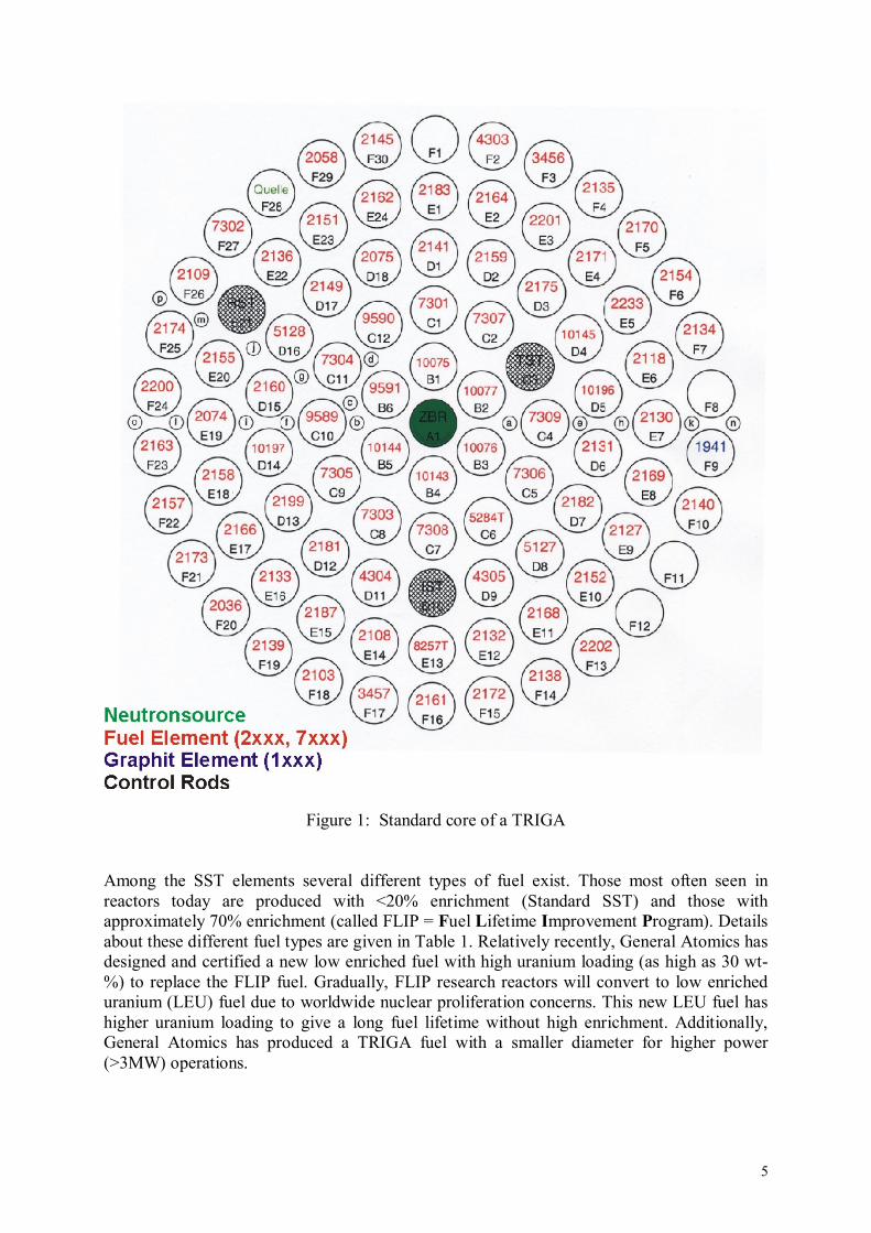
Figure 2: A unit cell of ZrH2. The tetrahedral structure of four zirconium atoms (light coloured) surrounding a hydrogen atom (black) is emphasized for one of the hydrogen atoms.
With the assumption of an Einstein model for the slowing down of neutrons in zirconium hydride, the basic physical processes, which occur when the fuel-moderator elements are heated can be described. A rise in temperature of the hydride increases the probability that a thermal neutron (~0.025 eV) in the fuel element will gain energy from an excited state of an oscillating hydrogen atom in the lattice. Since it has a longer mean free path for collision, the speeded-up neutron has an increased chance of escaping from the fuel-moderator element before being captured. However, the water channels between the fuel elements are very effective in re-thermalising any speeded-up neutrons which escape from the fuel; thus, the probability that a neutron will return to the fuel element before being captured elsewhere is not dependent on the temperature of the hydride but is in fact a function of the water. 1.8 Prompt negative temperature coefficient of reactivity TRIGA reactors may be licensed to operate with: 1. Standard Al-clad TRIGA fuel (20% enriched); 2. FLIP TRIGA fuel (70% enriched); 3. Standard SST-clad TRIGA fuel (20% enriched) (Note: The 20% enriched fuel may have a fuel loading of 8.5, 11, 20 or 30 wt-%)

11
The basic parameter which allows TRIGA reactors to operate safely during either steady-state or transient conditions is the prompt negative temperature coefficient associated with the TRIGA fuel and core design. This temperature coefficient allows great freedom in steady-state and transient operations. A major factor in the prompt negative temperature coefficient for the TRIGA cores is the core spectrum hardening that occurs as the fuel temperature increases. The rise in temperature of the hydride increases the probability that a thermal neutron in the fuel element will gain energy from an excited state of an oscillating hydrogen atom in the lattice. As the neutrons gain energy from the ZrH, the thermal neutron spectrum in the fuel element shifts to a higher average energy (i.e., the spectrum is hardened). This spectrum hardening is used differently to produce the negative temperature coefficient in standard and FLIP fuel. 1.9 Temperature coefficients of standard 20% Enriched Fuel As stated earlier, a large effort has gone into designing the TRIGA reactor in such a way that an increase in the temperature of the fuel element will result in a relatively large decrease in reactivity. This large prompt negative fuel temperature coefficient for 20% fuel is rather constant (see Fig. 3)) and is a result of the following three effects: 1.9.1 Cell and Non-homogeneous effects The 20% standard fuel element has an average neutron mean free path of ~3 cm, which is comparable to the average diameter of the element. The spectrum hardening effect discussed earlier, increases the mean free path for the neutrons considerably, and therefore, the probability of a neutron escaping the fuel element before capture is significantly increased as the fuel temperature is raised. In the water, the neutrons are rapidly re-thermalized so that the capture and escape probabilities are relatively insensitive to the energy with which the neutron enters the water. The heating of the moderator mixed with the fuel within a standard TRIGA element thus causes the spectrum to harden more in the fuel than in the water (keep in mind the TRIGA core is ~1/3 water). As a result, there is a temperature-dependent disadvantage factor for the core unit cell in which the ratio of absorptions in the fuel to total cell absorptions decreases as fuel element temperature is increased. This brings about a shift in the core neutron balance giving a loss of reactivity. Cell effect is an important contributor to the prompt negative coefficient. It should be noted that it is entirely dependent on the heterogeneous appearance of the core to thermal neutrons.

12
Figure 3: Typical prompt negative temperature coefficient vs. temperature. 1.9.2 Doppler broadening effects The uranium in the fuel elements is approximately 20% 235U and 80% 238U. The capture resonances in 238U are Doppler-broadened by an increase in the fuel temperature which in turn causes a decrease in the resonance escape probability (p). 1.9.3 Core leakage effects The core leakage contribution derives basically from the same mechanism that produces the cell effect. The core can be envisaged as a large super-cell with the reflector acting as the moderator. When the core heats up, leakage is increased and relatively more captures occur outside the fuel. Table 4 shows the components of the temperature coefficient for both an aluminium clad (ZrH1.0) and stainless steel clad (ZrH1.7) core. Note that the cell effect is the dominant contributor and the stainless steel clad cell has a substantially larger value than the aluminium clad cell. The stainless steel clad adds a poison region between the fuel element and cooling water, which acts as a barrier to neutrons returning to the fuel after having gained energy and escaped.

13
(×10-5 ∆k/ºC)
Aluminium clad cell, graphite reflected core
Stainless steel clad cell, water reflected core
Cell 4.7(50%) 8.2(65%) Doppler 2.1(20%) 1.8(15%) Leakage 2.9(30%) 2.1(20%) total 9.7 12.1
Table 4: Components of prompt negative temperature coefficient of TRIGA
reactors with 20% enriched fuel (The advantage of using ZrH1.7 hydride lies in the fact that the fuel matrix remains in a single phase well above 1000 ºC. With ZrH1.0, a fuel matrix phase change and an associated volume change occurs at approximately 530 ºC.) Because of the neutron spectrum hardening phenomenon, the temperature coefficient components (in the standard fuel) are increasing functions with temperature up to about 400 ºC and then they begin to decrease (refer to Fig. 4). The Doppler coefficient decreases slightly with temperature over the entire range of interest. The long delay times for transferring heat to the core cooling water coupled with the large prompt negative temperature coefficient of the TRIGA fuel-moderator element produce a reactor that is nearly linear rather than exponential in its response to reactivity changes.
Figure 4: Thermal neutron spectra vs. fuel temperature relative to σa vs. energy for Erbium-167.

14
1.10 Temperature coefficients of 70% enriched fuel For a TRIGA-FLIP fuel element, the 235U loading is about 3.5 times the loading of a standard TRIGA element. This causes the neutron mean free path in the FLIP element to be much shorter (~3 mm). For this reason, the escape probability for neutrons in the fuel is not greatly enhanced as the fuel-moderator material is heated. In the TRIGA-FLIP fuel the temperature hardened spectrum is used to decrease reactivity through interaction with a low energy resonance material. Thus erbium with its double resonance at ~0.5 eV is used in the TRIGA-FLIP fuel both as a burnable poison and as a material to enhance the prompt negative temperature coefficient. The neutron spectrum shift, pushes more of the thermal neutrons into the 167Er resonance as the fuel temperature increases, as illustrated in Fig. 4, where the cold and hot core spectra are plotted along with the energy-dependent absorption cross section for 167Er. As with a standard TRIGA core, the temperature coefficient is prompt because the fuel is intimately mixed with a large portion of the moderator and thus fuel and solid moderator temperatures rise simultaneously producing the temperature-dependent spectrum shift. For a TRIGA-FLIP core the effect of cell structure on the temperature coefficient is small. Almost the entire coefficient comes from temperature dependent changes in f and η (thermal utilization factor and reproduction factor) within the core and ~80% of this effect is independent of the cell structure. The calculated beginning of life prompt negative temperature coefficient is shown in Figure 5.
Figure 5: Prompt negative temperature coefficient vs. temperature for a typical TRIGA core. It is highly temperature dependent and increases rapidly as a function of fuel temperature because of the steadily increasing number of thermal neutrons being pushed into the 167Er resonance. The temperature-dependent character of the temperature coefficient of a TRIGA-FLIP core is advantageous because a minimum reactivity loss is incurred in reaching normal operating temperatures, but any sizeable increase in the average core temperature results in a

15
suitably increased prompt negative temperature coefficient to act as a shut-down mechanism. (From an operational point of view, the average number to use for a prompt negative temperature coefficient for a typical TRIGA core is ~1 ¢/ºC [7×10⁻⁵ δk/k per ºC]). Burn-up calculations made by GA indicate that after ~3000 MW days of operation the 235U concentration averaged over the core will be ~67% and the 167Er concentration will be ~33% of the beginning-of-life values. The temperature coefficient for such a core, including fission products will be less temperature dependent than the beginning-of-life coefficient because of the sizeable loss of 167Er and the resulting increased transparency of the ~0.5 eV resonance region to such neutrons. As a matter of interest, burn-up calculations also indicate that the FLIP cores will initially lose some reactivity for a short time and then will gain ~1.5% in reactivity during the first 1500 MW days of operation (see Fig. 6). This reactivity increase during the first half of core life is due to a mismatch between erbium and uranium burn-up. The reactivity gain due to erbium loss is somewhat greater than the reactivity loss due to 235U burn-up.
Figure 6: Cold core excess reactivity vs. core operation time. The addition of Erbium to the fuel-moderator matrix does not compromise the chemical, mechanical or nuclear characteristics of the fuel in comparison with its extensively demonstrated characteristics as standard TRIGA fuel. The major changes and effects resulting from the addition of the erbium are: a) Allowance of higher uranium enrichment to produce a much longer-burning core than
standard TRIGA fuel. b) A shortened prompt neutron lifetime compared with a standard core (~19 µs vs. 39 µs).
This results from the heavier core loading of uranium and the erbium, but has no direct

16
effect on steady-state operation. The reduced lifetime does give shorter periods and higher peak powers during a transient when compared with a core with standard fuel (assuming equal reactivity insertions and an equivalent temperature coefficient). However, the reduced lifetime has no influence on the energy release or on fuel temperatures produced during a pulse. Since the operational limits of the system are based on fuel temperature, and since this change in neutron lifetime does not affect fuel temperatures, there is no resulting compromise in the safety of the system.
c) A change in shape of the prompt negative temperature coefficient as a function of
temperature. This is the most significant change in a core with FLIP fuel vs. standard fuel, and the desire to have the greatest possible confidence in this parameter was the reason for extensive calculations and the conducting of an in-core test program. Results from these studies give a design prompt negative temperature coefficient, which becomes increasingly negative as the core temperature increases (compared with the nearly constant value for standard fuel), and has an average value over the operational core temperature range (20ºC - 700 ºC), which is essentially the same as the coefficient for a standard core. For large temperature changes, the temperature coefficient is on the same order as the standard fuel. The nearly linear response of core reactivity, due to a temperature change, requires the operator to provide more control rod compensation in reaching full power when compared to a standard core. However, the prompt temperature rapidly inserts a negative reactivity proportional to the temperature change during any rapid power transient (see Fig. 7 for a graphic example of this inherent characteristic).
Figure 7: Calculated peak power and fuel temperature rise vs. time during power excursion.

17
1.11 Pool temperature coefficient of reactivity The pool temperature coefficient (or sometimes called bath coefficient) describes the change in reactivity associated with a change in pool temperature and is defined as the change in reactivity per unit change in pool temperature. Whenever the reactivity and the temperature change in the same direction, the pool coefficient is positive. If the reactivity and the temperature change in opposite directions, the pool coefficient is negative. The pool coefficient has been measured experimentally in TRIGA reactors and has been found to be small but positive in the less than room temperature region, becoming negative at higher temperatures. The measured pool coefficient in a TRIGA averages ~0.05 ¢/ºC (½ ¢ for each 10 ºC change). Thus, very little reactivity change is a direct result of pool temperature. The temperature of the pool water does not change significantly during a prompt transient. The prompt transient behaviour of the reactor is primarily determined by changes in fuel temperature. 1.12 Void coefficient of reactivity If water in the core is replaced with a very low density material, i.e., steam, gases, etc., a negative reactivity change will occur. This is called the void coefficient of reactivity. The void coefficient of reactivity is defined as the change in reactivity per percent void of core water. The void coefficient is a function of position in the core, water fraction, and water temperature. This quantity is useful in studying the effects on reactivity produced by the formation of voids within the core. This could occur, for example, with the production of steam and/or radiolytic gases such as hydrogen or oxygen along the surface of a fuel element. 1.13 Fuel element reactivity worths Perturbations of reactivity resulting from physical changes in the core and reflector are of importance to the safety of the reactor. The reactivity changes shown in Table 5 have been measured by removing one fuel element at a time. This gives a reactivity value relative to the water-filled fuel location in an otherwise completely loaded core.
Core position Reactivity value in [¢]
B 130 C 90 D 55 E 42 F 37 F (graphite element) 8
Table 5: Fuel element reactivity worth in cents measured at a TRIGA Mark II reactor.
18
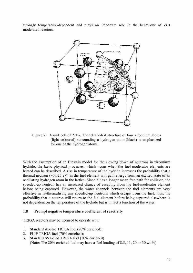
1.14 Power coefficient of reactivity The power coefficient describes the change in reactor power associated with a change in reactivity and is defined as the amount of reactivity needed to change the reactor power by one kilowatt. TRIGA reactors have a strong negative temperature coefficient, and a certain amount of reactivity is needed to overcome this effect during reactor power increases. The variable temperature coefficient associated with the FLIP fuel precludes a constant power coefficient. However, an overall average power coefficient of ~25 ¢/kW can be used for a TRIGA with reasonable results. See Figure 8 for a typical TRIGA reactivity loss versus power curve.
Figure 8: Typical reactivity loss versus power. If an operator wants to know how much total reactivity would have to be added to the just critical core in order to reach 1000 kW, he can use the power coefficient (αp): αp = ~0.25 ¢/kW; P = 1000 kW (P)( αp) = reactivity (¢) (1000 kW)(0.25 ¢/kW) = 250 ¢ = $ 2.50. This reactivity can be expressed in % δk/k: ($)(β) = ρ; ($ 2.50)(0.007) = 0.0175 δk/k = 1.75% δk/k. 1.15 Reactor nuclear parameters The parametric values listed in Table 6 are estimated for TRIGA reactors from calculations correlated with measurements made on other reactors of the same generic type. Although each reactor is slightly different due to its core configuration, the values given here are reasonable extrapolations. No unqualified estimate of the accuracy of the information presented herein has been made but, in general, it should be good within about 5%.

19
Cold clean critical core 57 elements
2.055 kg 235U Operational loading after 40 years of operation 90 elements
3.52 kg 235U Prompt neutron lifetime 43×10-6 s
Effective delayed neutron fraction βeff = 0.0070 Prompt negative temperature coefficient -1.0×10⁻⁴ δk/k ºC
Table 6: Nuclear parameters of a typical TRIGA Mark II reactor
1.16 TRIGA Pulsing Performance For transient (pulsing) operation the reactor is first brought to criticality at a low power level (usually 10 to 300 watts). This is accomplished by drawing only the standard control rods and leaving the transient rod in the core. Some facilities bring the reactor critical with all controls rods and then lower the transient rod to produce a subcritical pulse. Reactivity insertion is calculated by evaluating the differential transient rod worth curves and selecting the transient rod height. The pulse is then produced by rapidly firing the transient rod out of the core pneumatically within a fraction of a second. The reactor power will increase sharply to a value that will result in a fuel temperature increase, which will compensate for the excess reactivity inserted. At this point the peak reactor power will occur. The fuel temperature will continue to rise resulting in an increasing loss of reactivity, and the reactor power will decrease to a comparatively low level. This final power level depends on the reactivity insertion and the heat transfer characteristics of the fuel element. The power level after the transient is referred to as the after-pulse tail and is produced from the power decay of the original pulse and the delayed neutron affects. After initiation of the transient pulse, the reactor is automatically scrammed after a few seconds to clip the power tail for operational convenience. A typical TRIGA reactor pulse for a reactivity insertion of $ 1.994 is shown in Figure 9. A pulse for a FLIP reactor will be narrower with a higher peak power for the same reactivity insertion.
0 10 20 30 40 50 60 70 80 90 1000
100
200
300
400
500
600
Powe
[MW
]
time [ms]
Identification ......... 130009012003Number ................. 1300Date & Time ............ Thu Jan 9 13:45:01 2003Peak Temperature ....... 259 CPeak Power ............. 523 MWTotal Energy ........... 12.551 MW secsWidth at Half Power .... 21.700 msecMinimum Period ......... 6.382 msecReactivity ............. 1.994 $
Figure 9: Typical TRIGA reactor power pulse.
20
1.17 The Fuchs-Nordheim model and pulsing characteristics The performance of a TRIGA reactor pulsing beyond prompt critical can be quite well described by a space-independent kinetics model in which heat transfer and delayed neutrons are neglected. In this model, usually called the Fuchs-Nordheim model, the reactor parameters that appear are:
l = prompt neutron lifetime (s), α = prompt negative temperature coefficient (l/k dk/dt), θ = fuel temperature, h = ratio of peak to average fuel temperature in core, C = total heat capacity of metal in core. T = reactor period in seconds
If a sudden insertion of reactivity beyond prompt critical (δkp) is made, the reactor power will initially rise exponentially as exp(t/T) where the period T is given by l/ δkp. This period will change when appreciable temperature is generated by the pulse. Assuming a constant heat capacity and a shutdown mechanism that is prompt and invariant with temperature, the reactor temperature will rise by δkp/α, until the reactivity inserted beyond prompt critical is just compensated by the fuel temperature rise. The power will then fall to very low values with a temperature overshoot by about a factor of two beyond the temperature at the peak power value. The total energy release in the pulse will be:
α
δ== pkC2
bT2E .
The peak power will be:
lα
δ==
2)kC(
bT21p
2p
2max ,
and the width at half-maximum power of the pulse will be ~3.5 T. The shutdown coefficient, b, is given by
C
bl
α= .
The average fuel temperature is:
α
δ==θ pk2
CE ,
and the maximum fuel temperature is:

21
ChEhˆ =θ=θ .
It can be seen that the peak power varies as the square, and the energy release varies linearly with the prompt reactivity inserted (δkp). The heat capacity of the TRIGA fuel element increases with temperature, and a Fuchs-Nordheim analysis with variable heat capacity has been derived by R. Scalettar* and is used for current TRIGA kinetics analysis. (For a $ 3.00 pulse in the GA Advanced TRIGA Prototype Reactor, a difference of ~20% in peak power and energy release is noted between a constant versus a variable heat capacity analysis, with the higher values resulting from the constant heat capacity model.) The simple Fuchs-Nordheim model relationships are helpful in understanding the pulsing characteristics of the TRIGA reactors since the influence of each parameter on the pulse behaviour of the system is apparent. Figure 10 illustrates a power pulse from the GA TRIGA Mark I reactor using standard TRIGA fuel (aluminium clad) and compares it with a Fuchs-Nordheim model computation.
Figure 10: Power level as a function of time for GA TRIGA Mark I transient. ___________________________ *R. Scalettar: "The Fuchs-Nordheim Model with Variable Heat Capacity". General Atomic Report GA-3416, General Atomic Division of General Dynamics Corporation, 13. 8. 1962.

22
1.18 How to estimate the peak power of a pulse It is difficult to calculate peak power for any given pulse using the methods and formulas described so far. This is especially true when using the 70% enriched FLIP fuel. The reason is that there are too many variables involved. Some of these are:
1. Variable heat capacity 2. Variable negative temperature coefficient 3. Questionable reactivity insertions 4. Core history and xenon concentration 5. Transient rod air pressure at the instant of the pulse (affects rod acceleration).
A computer program would be required to correlate precise predictions for peak power vs. reactivity insertion for various pulses. Routine operational estimates of the pulse size can be made by using a ratio with known quantities. The expression most commonly used is:
2p
22
p
1)k(
p)k(
p
21δ
=δ
p1 = last known pulse size (MW) p2 = projected pulse size (MW) δkp1 = prompt reactivity ($-1) for the last known pulse
(Remember this quantity is squared in the expression.) δkp2 = prompt reactivity selected for the projected pulse.
Example Question: What size pulse will a $ 2.10 reactivity insertion produce? Answer: Look in the log book for the last pulse parameters;
p1 = 2100 MW δk1 = $ 2.25 (Remember that prompt reactivity is reactivity greater than $ 1.00.) δkp1 = $ 1.25
given: δk2 = $ 2.10 δkp2 = $ 1.10
2p
22
p
1)k(
p)k(
p
21δ
=δ
22
2 )10.1(p
)25.1(2100
=
2p56.1
)21.1()2100(=

23
1629 = P2 1629 MW peak power. Energy releases can be estimated in the same way by using the expression:
21 p
2
p
1kE
kE
δ=
δ ,
E = energy released (MWs). Notice in the energy expression that the prompt reactivity is not squared. 1.19 Reactivity accident It has been shown in various TRIGA analyses and confirmed by an adiabatic model that accidental pulsing from a high power level, e.g. 1 MW, would actually result in lower peak fuel temperatures as compared to regular pulses initiated by the same reactivity insertion from a low power level. This is due to the larger prompt negative temperature coefficient at the higher fuel temperatures, and also due to the fact that the feedback effects are significant from the moment the transient rod starts to withdraw. Thus, a much smaller pulse is experienced and the adiabatic fuel temperature peak is less than in a comparable pulse from low power, in spite of the higher initial fuel temperatures. 1.20 TRIGA Safety Compared to Other Research Reactors 1.20.1 Summary The most pertinent information regarding safety of research reactors comes from specific test data developed in experiments at the National Reactor Testing Station (now the Idaho National Engineering Laboratory) SPERT facilities In Idaho, and at the GA TRIGA facilities in San Diego, California. An analysis of these data clearly indicates that the TRIGA reactor has the greatest inherent safety of any available megawatt level research reactor. The safety of the TRIGA is due to the large prompt negative temperature coefficient of reactivity, which is an intrinsic characteristic of the standard U-Zr-H fuel. The TRIGA temperature coefficient acts independently of any external controls to assure safe and reliable self-shutdown in the event of an accidental reactivity insertion. 1.20.2 Review of Some Reactor Safety and Failure Tests The SPERT tests, with aluminium-uranium alloy plate type fuel with light water cooling and moderation, showed that a reactivity insertion of about $ 2.40 results in fuel plate damage and that a $ 3.60 reactivity insertion results in a violent destruction of the core. Tests on plate-type aluminium-uranium alloy fuel using D2O moderator and coolant show that fuel melting will occur with about $ 3.50 insertions. In one SPERT test, using a core loading of low-enrichment stainless clad UO2 fuel, a reactivity insertion of about $ 2.70 resulted in a rupture-failure of two fuel elements with an additional 140 to 150 elements bowed by a 3.4 bar to 4.1 bar pressure surge. The above reactivity insertions resulted in damage or failure with a single pulse, indicating that considerably smaller insertions may cause failure for repeated routine pulses. By contrast, TRIGA pulse experiments have shown that the TRIGA standard fuel can safely withstand

24
numerous $ 4.00 reactivity insertion pulses with complete safety. Further, the TRIGA can handle much larger pulses. In this regard, it is significant that the GA TRIGA Prototype Reactor facility was licensed for pulses with up to $ 5.00 reactivity insertions. The facility is located in a conventional building adjacent to the GA Research Laboratories near San Diego, California. The GA TRIGA reactors in San Diego have been shutdown at this time and are in the process of decommissioning. It has been demonstrated that TRIGA reactors can operate with the dual capability for up to 5 MW steady-state and 9000 MW routine pulses. Steady operation up to 1.5 MW is conducted with natural convection core cooling, and $ 4.00 pulses to 5000 MW are run routinely at rates up to 12 pulses per hour.

25
FIGURES AND TABLES Figure Title Page 1 Standard core of the TRIGA reactor Vienna 5 2 A unit cell of ZrH2. The tetrahedral structure of four zirconium atoms (light coloured) surrounding a hydrogen atom (black) is emphasized for one of the hydrogen atoms 10 3 Typical prompt negative temperature coefficient vs. temperature 12 4 Thermal neutron spectra vs. fuel temperature relative to σa vs. energy for Erbium-167 13 5 Prompt negative temperature coefficient vs. temperature for FLIP fuel 14 6 Cold core excess reactivity vs. core operation time 15 7 Calculated peak power and fuel temperature rise vs. time 16 8 Typical reactivity loss vs. power 18 9 Typical TRIGA (FLIP) reactor power pulse 19 10 Power level as a function of time for GA TRIGA Mark I transient 21 Table Title Page 1 Principal fuel element design parameters 6 2 Calculated power per element (FLIP type) 6 3 Calculated maximum, minimum and average power per element (FLIP type) 7 4 Components of prompt negative temperature coefficient 13 5 Fuel element reactivity worths in cents 17 6 Nuclear parameters of a typical TRIGA Mark II reactor 19

![The NUSTAR project at FAIR · the prototype TRIGA-SPEC[24], in operation at the TRIGA research reactor in Mainz. Figure 2. Part of the NeuLAND detector being assembled for beam tests](https://static.fdocuments.net/doc/165x107/5f96d56c9211b330077062c4/the-nustar-project-at-fair-the-prototype-triga-spec24-in-operation-at-the-triga.jpg)