
TRIGA Reactor Main systems june - OSTI.GOV
37
TRIGA REACTOR MAIN SYSTEMS H. Böck and M. Villa AIAU 2730( *prepared for NTEC
Transcript of TRIGA Reactor Main systems june - OSTI.GOV

TRIGA REACTOR MAIN SYSTEMS
H. Böck and M. Villa
AIAU 2730(
*prepared for NTEC
2
Overview This module describes the main systems of low power (< 2MW) and higher power ( ≥ 2 MW) TRIGA reactors. The most significant difference between the two is that forced reactor cooling and an emergency core cooling system are generally required for the higher power TRIGA reactors. However, those TRIGA reactors that are designed to be operated above 3 MW also use a TRIGA fuel that is specifically designed for those higher power outputs (3 to 14 MW). Typical values are given for the respective systems although each TRIGA facility will have unique characteristics that may only be determined by the experienced facility operators. Due to the inherent wide scope of these research reactor facilities construction and missions, this training module covers those systems found at most operating TRIGA reactor facilities but may also discuss non-standard equipment that was found to be operationally useful although not necessarily required. Learning Objectives
1. You should understand the instrumentation and control systems, which are generally required for TRIGA research reactors.
2. You should understand those additional systems required for higher operating
powers or specific facility needs.
3. You should be able to explain the operation of various types of neutron detectors.
4. You should be able to evaluate the operation of a standard research reactor instrumentation system and compare to an advanced, digital console.
5. You should be able to evaluate your facility Safety Analysis Report and determine
if additional equipment or facility modification is needed to improve the safety or safety margin of the reactor.

3
CONTENT Page Overview 2 1. Introduction 4 2. Primary coolant circuit 4 2.1 TRIGA Reactors with natural convection cooling (< 2 MW) 4 2.2 TRIGA reactors with forced cooling (≥ 2MW) 5
2.2.1 System description 5 2.2.2 Component Description 7 2.2.3 Instrumentation and Control 8 2.2.4 Emergency Core Cooling System (ECCS) 9 3. Water purification circuit 11 4. Water make-up system 12 5. Secondary coolant circuit 12 5.1 Secondary Cooling System of a Low Power TRIGA Reactor 12 5.2 Secondary Cooling System of a High Power TRIGA Reactors 13 5.2.1 Component Description 13 6. Reactor hall ventilation system 14 7. Area monitoring system 15 8. Fresh and spent fuel storage 15 9. Underwater precision measurement tool for fuel elongation 16 and bowing measurement 10. Fuel transfer cask and spent fuel inspection container 16 11. Reactor Protection System (RPS) 17 11.1 Nuclear Instrumentation 17 11.1.1 Neutron Detectors 18 11.1.2 BF3 proportional counters 19 11.1.3 Boron (10B) lined detectors 19 11.1.4 Fission chambers 22 11.2 Reactor protection and power regulating system 23 11.3 A typical TRIGA instrumentation 24 11.3.1 System Design 24 11.4 Operational experience 25 List of Figures 27
4
1. INTRODUCTION Reactor main systems are those important for the safe operation of research reactors. They may be divided into safety and support systems. Support systems are often not considered as safety systems but their failure may cause indirect effects on reactor safety Therefore, experienced operators must realize that these support systems require routine, periodic maintenance to be carried out with the same care as any other safety related system. The most important components or functions of the described main systems are inspected or evaluated at regular intervals following a maintenance and inspection manual or procedures as approved by the respective Regulatory Body which licensed the reactor. 2. PRIMARY COOLANT SYSTEM 2.1 TRIGA Reactors with Natural Convection (NC) Cooling (< 2 MW) General Atomics has determined that Standard TRIGA fuel elements may be safely operated up to 2 MW with natural convection cooling. Heat transferred from the fuel elements to the primary coolant in the tank is carried from the core by natural convection cooling with low power TRIGA reactors. These reactors may be operated for short periods with natural convection cooling up to a power level of approximately 100 kW. However, additional pool cooling may be required to maintain average bulk pool temperatures within permitted values if continuing operations are expected. Above a nominal power level of 100 kW, the secondary cooling system circulation pump should be turned on to remove reactor heat and, through the diffuser system flow, to interrupt the direct, upward flow of N-16. The primary coolant circuit is composed of the reactor tank, one or more primary pumps, a heat exchanger (plate type or tube type heat exchanger), filters and associated piping and valves. Two typical designs are shown in Fig. 1. When forced cooling is used, the primary water is pumped from the reactor tank through a pipe (typically 100 mm stainless steel) and directed from the reactor platform downwards into the basement of the reactor building or into an adjacent room. Usually a water outlet temperature sensor (TA) is installed in this section of the pipe for system evaluation. The first major component in the primary loop is usually a filter box with a set of candle type filters (25 µm) to remove small suspended particles carried along with the primary water. This filter acts to protect the primary pump and minimizes the fouling of the heat exchanger surfaces. An expansion below may be located in the subsequent piping to allow thermal expansion. The primary pump(s) could be made of aluminium but stainless steel pumps are now more frequent, typical horsepower is 10 - 15 kW. In some cases, the primary flow (and hence, pool temperature) can be regulated by an automatic control. Normally the maximum flow is about 30 m3/h for a low power TRIGA reactor. A conductivity sensor (σ1) and a pressure sensor (P1) are sometimes installed after the pump and before the heat exchanger inlet. The heat exchanger for many facilities are tube and shell type in which the primary coolant passes through the heat exchanger’s small internal tubes and the secondary coolant flows around the tubes. Some facilities have replaced their traditional tube and shell type with plate-type heat exchangers. Plate-type heat exchangers have a larger heat transfer surface area and this results in a smaller heat exchanger for the same capacity. Additionally, the plate-type may have additional plates installed to increase the capacity further with only a small change in the overall size.

5
A second conductivity cell (σ2) is installed after the heat exchanger. The conductivity cells before and after the heat exchanger are used to compare heat exchanger inlet- and outlet primary coolant conductivity and give operators an indication of a possible heat exchanger leak. A secondary water leak into the primary water is possible because the pressure in the secondary cooling system is always higher than on the primary side (this is to prevent an inadvertent release of radioactive coolant to the secondary). A defect or tube leak in the heat exchanger may be indicated by an increase in the conductivity difference across the heat exchanger. From the heat exchanger room the primary coolant pipe penetrates back into the reactor hall upwards to the reactor platform. A flow meter (Φ) and an inlet temperature (TE) sensor are installed in the primary coolant pool return piping. In most cases the inlet temperature into the tank is between 20 and 25°C at 250 kW. This return temperature is dependent on the cooling capacity of the primary and secondary systems. Larger reactors may have difficulty maintaining a constant return temperature due to inherent system inefficiencies; e.g. hot, humid conditions limiting the cooling capacity of the evaporative cooling tower. Modern primary coolant systems at research reactors may be completely made of stainless steel or a mixture of stainless steel and aluminium. Materials used to construct or repair the cooling system must be selected for corrosion resistance and compatibility with existing systems. Pump, pipes and heat exchanger may be obtained from the milk- or soft drink industry suppliers at a lower cost if they have the same purity and quality requirements as the nuclear industry. Heat exchangers should be cleaned about every 10 years on the secondary side to remove deposits (mineral scale or biological fouling). These deposits depend on the secondary water quality control and reduce the heat transfer coefficient. Monitoring of heat exchanger fouling may be performed by careful evaluation of the inlet and outlet temperatures and pressures over time. Maintaining water chemistry on the secondary side may reduce the frequency of cleaning but improper or excessive chemical addition that could potentially cause heat exchanger tube leakage. Replacing the gaskets or seals is recommended after the cleaning of a plate type heat exchanger to prevent leakage during subsequent operations. 2.2 TRIGA Reactors with Forced Convection (FC) Cooling (≥ 2 MW) 2.2.1 System Description Higher powered TRIGA research reactors (≥2 MW) have more elaborate primary cooling systems. Additionally, because the forced cooling flow is required for the higher power operation, monitoring of the coolant flow and temperatures is required and become an integral part of the reactor protection system. Standard TRIGA fuel may be operated up to 3 MW with forced convection cooling, but TRIGA fuel designed for higher power (one difference from Standard fuel is the smaller fuel element diameter) will also have these same systems.

6
Additional systems that are required for higher power TRIGA reactors are
1. A primary cooling system, which transfers the heat generated in the reactor core by forced convection but also permits natural convection cooling for low power operation or decay heat removal.
2. A decay tank or hold-up system that permits the decay of N-16, which is a neutron activation product, in a shielded area before returning the coolant to the tank.
3. Emergency core cooling system (ECCS), which supplies water to the reactor core in the event of a tank draining or loss of coolant accident (LOCA) and thus protects the integrity of the fuel cladding by removing the decay heat.
Primary Cooling System Due to the flow restrictions and losses added to the system from the additional forced cooling piping around the reactor, the forced/natural cooled reactor can only be operated in a natural circulation mode at power levels up to 500 kW or in a forced down-flow mode at higher power levels. The heat generated in the reactor core is transferred to a secondary water-cooling in a similar fashion to the bulk cooling system described in Section 2.1 above. The secondary system transfers the heat to a cooling tower or other heat sink, where the heat is removed. The reactor heat is transferred directly to the bulk water in the reactor tank in the natural convection cooling mode until temperature limits require outside forced cooling of the pool. The primary cooling system and connected systems of a typical high power (in this case, 3 MW) TRIGA facility are shown in Fig. 2. As noted before, the higher power TRIGA cooling systems actually have two modes of operation; forced and natural convection cooling. Natural Convection (Low Power Operations) Cooling In this mode of operation, the primary pumps remain turned off and the reactor core is cooled by the pool water flowing down past the outer fuel elements and up past the inner fuel elements. This pattern is established by the available coolant and the radial power profile across the reactor. This flow pattern has been verified by several tests conducted at the TRIGA reactor at the University of Illinois. A mode switch on the reactor control console limits the reactor power and sets the safety system settings for the fuel temperature at values permissible under forced convection flow mode of operation. The operating time of the reactor is limited by the rise in bulk pool temperature. The dose rate at the top of the reactor should be monitored since the N-16 produced in the core will rise directly to the pool surface in the natural convection mode. An additional diffuser pump may be considered if dose rates are determined to be an operational problem in natural convection mode. Forced Convection Cooling In the forced convection mode, the coolant is pulled down through the core by the suction of one or more primary coolant pumps. The primary flow rate (approx. 13 m3/min) must be achieved and stabilized before the reactor is turned on or the reactor will scram immediately as a result of a “low flow” signal. In the forced convection mode, the primary coolant enters the reactor tank through a 25.4 cm line near the top of the pool. The coolant is drawn by pump suction down through the core upper shroud and through the reactor core into the core lower plenum. The coolant enters a 30.48 cm diameter pipe from the lower plenum and travels in a shielded trench to the N-16

7
decay tank. Two pumps, operating in parallel, pump the coolant from the N-16 decay tank, through the heat exchanger and back to the reactor tank. The reactor suction line is positioned within the tank to flow up above the reactor core before exiting the tank. This pipe has an anti-siphon line provided that allows air into the suction line if the water level in the tank drops below 4.42 m from the normal pool level. This prevents the primary pumps from pumping the reactor core dry in the event of a break in the primary cooling system downstream from the pumps. The anti-siphon line is a backup to the float-level switches, which normally turn the primary pumps off when tank level drops below a nominal value.
2.2.2 Component Description N-16 Decay Tank
Since oxygen is present in the reactor tank water, N-16 is produced in the reactor tank through the (n, p) reaction. The transport time from the reactor core to the pump and heat exchanger is too short for much of the N-16, with its 7.4 sec half-life, to decay before it reaches the pump. The decay time is increased by means of a delay tank with internal baffles. The decay tank holds the coolant for approximately 143 seconds before the coolant reaches the pump. This delay period is sufficient to allow the N-16 to decay to levels, which do not require shielding beyond the delay tank. The pipeline from the reactor core to the delay tank is shielded by approximately 1.2 m of concrete. An isolation wall is made of shielding blocks having a steel door to facilitate shielding as well as access restriction. Closed Circuit Television (CCTV) and lighting provision in the decay tank vault room may be considered for periodic inspection during reactor operation. The N-16 decay tank can be either made of aluminium alloy (6061-T6) or stainless and typically has a volume of approximately 30 m3. Some older facilities with aluminium tanks have experienced leakage caused by corrosion of the decay tank and associated piping as it passed through walls or underground. Routine preventative inspections should include internal inspections of these components every few years. Pumps The primary cooling system has two centrifugal pumps. Both pumps may be operated in the forced mode or one pump is operated with the other pump as a standby pump if reactor power level permits. Discharge capacity of each pump is about 6.6 m3/min and the maximum pressure is approx. 2000 kPa at 100°C. The pumps are turned on or off by push-button switches located in a side cabinet adjacent to the reactor control system console or from the primary pump panel board located in the primary pump room. Heat Exchanger Either tube/shell type or plate type heat exchanger can be used, the latter having the advantage that it’s heat exchange area can be extended. Many of the recently installed heat exchangers are high thermal efficiency plate type exchangers with 50 to 60 plates and an overall heat transfer area of about 20 to 25 m2 for a 250 kW system. Plate type heat exchangers have the advantage of being very compact, they can be opened and cleaned easily and they allow the possibility to increase the cooling capacity by increasing the heat transfer area. Traditional tube and shell type heat exchangers are still in use (especially for higher power levels) but may gradually be replaced by plate type heat exchangers.
8
Piping and Valves
1. All piping and fittings in the system are of aluminium alloy for corrosion resistance and material compatibility.
2. Butterfly valves in the system are of aluminium construction with synthetic rubber seals. 3. Gate and globe valves are of aluminium construction and have Teflon packing. 4. Check valves used in the outlet of each primary pump prevent reverse flow when a
pump is shut off and are constructed from a cast aluminium body, aluminium internal assembly and Buna-N seals.
2.2.3 Instrumentation and Control The primary cooling system is designed to pump 13.2m3 of demineralised water through the reactor core to remove 3000 kW of heat. The core maximum inlet temperature is 40.6°C and the average temperature rises through the reactor core at 3 MW is 4.3°C. Coolant flow rates, temperatures, and pool water level are monitored to ensure that the system is operating properly. In the event of an accident or equipment failure, the control system is designed to shut down the reactor. The process flow and instrumentation diagram can also be seen from Fig. 2. The instrumentation and control system has the following features: Pool Level Measurement and Alarm a. A continuously indicating pool level meter provides visual indication of normal pool level
to the operators in the control room. The meter monitors pool level in the range from 30 cm above to 4.2 m below normal. For some facilities, a local level indication of pool level at the pool surface may consist of a simple series of marks calibrated in litres, gallons or depth but operators must routinely (at least once a day) record the level. Routine monitoring of pool level is important to evaluate evaporation rate. An unusual change in pool level may indicate a primary leak or a secondary to primary leak.
b. Indication of catastrophic or rapid pool level decrease is provided by redundant float level
switches located approximately 0.9 m below the normal pool level. Additional switches at some higher level (perhaps 0.1 m below normal level) may be provided to alert the operators of an abnormally low pool level. These switches monitor the integrity of the reactor tank and primary coolant piping. A large, rapid drop in pool level will indicate a major leak in the reactor tank, the delay tank, or the piping system. Upon a major loss of pool water, the float level switches will initiate the following actions:
(1) Scram the reactor. (2) Stop the primary pumps. (3) Automatically close the inlet and outlet valves leading to and from the reactor pool.
c. A second set of redundant float level switches is located 4.6 m below normal pool level. These switches will activate the emergency core cooling system described later in this chapter.
Coolant Flow Measurement and Alarm A flow-measuring device is installed in the core exit line at a location between the shield structure and the delay tank. This device will measure the flow and display the flow rate in the control room. The device will provide a visual and an audible alarm when the flow is less than

9
12.5m3 /min and will shutdown the reactor if the flow is below 11.7 m3/min in forced convection mode. The alarm and scrams are bypassed when the reactor is in the natural convection mode. An additional coolant flow signal may be supplied to the reactor power meter, which calculates and displays the reactor power as determined from the coolant flow rate and temperature rise through the core. A flow switch is installed downstream from the flow-measuring device. The flow switch is a reserve in case of failure of the flow measurement device to indicate low flow. The flow switch will also shutdown the reactor, close the valves, and shut off the pumps. Primary Coolant Temperature Measurement Core inlet and core outlet temperatures are measured and displayed in the control room. A single meter and a selector switch will permit display of the following parameters: coolant flow rate; average coolant inlet temperature; any one of up to four coolant inlet temperatures; average coolant temperature rise through the core; core exit temperature. a. Four platinum resistor temperature sensors (RTDs) are located just above the top of the
reactor fuel to measure the core inlet coolant temperature. The sensors are supported by the top fitting of the fuel elements and may be located over any standard fuel element. Two of these temperature sensors are a part of the reactor safety system and will alarm on core inlet temperatures above 40.6oC and scram at 43.3°C. The core coolant inlet temperature scram system does not operate when the reactor is in the natural circulation mode of operation. The average of the four inlet temperatures or any combination of the four can be displayed and used to calculate reactor power.
b. A temperature sensor is located in the core coolant exit line between the reactor pool and the
N-16 decay tank to measure the core outlet coolant temperature. This temperature can be displayed and is also used to calculate reactor power.
c. Core exit, core return and bulk pool temperatures are also indicated by a meter and three-
position selector switch on the control console. There are local temperature gages for the primary side of the heat exchanger. These are independent of the water system control and instrumentation system.
2.2.4 Emergency Core Cooling System (ECCS) For most small research reactors, decay heat is generally not a problem due to power level or power history. In some cases, natural convective cooling by air is sufficient to prevent core damage if the power history before shutdown is not high or sufficient cooling time is provided following shutdown. Studies by General Atomics have shown that the maximum temperature that standard fuel can tolerate, in air without damage to the clad and subsequent release of fission products, is l650° F (900° C). For FLIP fuel, this value is 1720° F (940° C). High cladding temperatures will cause abnormally high hydrogen gas pressures internal to the cladding with potential swelling or failure of the element cladding. In general, this temperature will not be exceeded under the conditions of coolant loss if the maximum power density in an element equal to or less than 21 kw for standard fuel and 23 kw for FLIP fuel even if the reactor is operated for an infinite time prior to the accident. For higher power TRIGA reactors a decay heat removal system may be required for emergency cooling of the fuel following a lost of coolant accident (LOCA). In order to protect the fuel following a reactor shutdown, the reactor core must be covered with water for a period of time following the loss of

10
the primary coolant to remove the reactor decay heat. The emergency core cooling system should be designed to meet this requirement. The following is a description of an ECCS for one high power TRIGA reactor. Individual facilities may develop a different emergency cooling system design but it must still meet the guidance and requirements of the regulatory body. Because a LOCA implies no coolant over the reactor core, avoiding high radiation exposures should be considered in the design and operation of an emergency cooling system. A system generally consists of the reactor core assembly, two float level switches, a source of coolant such as the N-16 decay tank, a battery operated pump, and a backup water supply. The reactor core assembly includes an upper shroud, which is designed to retain 76.2 cm of water over the reactor core in the event of a tank or beam tube rupture or a break in the primary coolant line. This facility is internal to the reactor tank and would retain the water even if the entire reactor tank were drained around it. The water retained within the core assembly will remove the fission product decay heat from the fuel element by natural convection within the emergency cooling shroud. The heat is transferred to the atmosphere primarily by evaporation. As the water is boiled out of the reactor core assembly, it must be replaced by the emergency core cooling system. Two redundant float level switches act to detect an abnormally low or zero pool level and turn on the emergency pump. The pump and the float level switches receive their electrical power from a 12 VDC Ni-Cd battery set. The battery is connected to the building emergency electrical power system to maintain the battery fully charged. The capacity of the battery is 168 Amp-hr and permits the ECCS pump to operate approximately 28 hours. The battery operated (chargeable) emergency pump of 3.8 litre/min capacity will pump water from the N-16 decay tank into the reactor core assembly. A flow switch is installed in the emergency line to provide verification that water is flowing to the core. The water to the core flows into the lower plenum through the line normally used to break the suction to the primary pumps. A backup system is provided by connecting the reactor building rooftop 7560 litre water tank to the emergency piping system through a normally closed and pad-locked valve. This 7.5 m3 tank is supplied from two sources for redundancy. One of the sources is from the central water system and the other is the 75 m3 underground tanks and pump system. This backup system can be used in the event of failure of the emergency pump or loss of water from the N-16 decay tank. The backup system is manually controlled with the flow provided by the gravity flow from the storage tank. The loss of coolant analysis for a 3 MW TRIGA reactor indicates that it will require approximately 0.75 hours for the initial charge of water in and above the core to begin boiling and an additional 8.6 hours for the water above the core to boil off, thus allowing time to start the backup system if required. Decay Heat Removal System To remove the heat produced by the decay of the fission products after a normal reactor shutdown with no reactor tank leak, the reactor cooling system is operated until the reactor pool water temperature falls to either 30°C or ambient temperature. Maintaining the tank temperature at a lower temperature will minimize the evaporative coolant losses and reduce the ambient humidity near reactor control components (e.g. rod drives and detector cables).
11
As discussed in Section 2.2.4, the reactor core assembly includes an upper shroud, which is designed to retain 76.2 cm of water over the reactor core in the event of a tank or beam tube rupture or a break in the primary coolant line. The water retained within the core assembly will remove the fission product decay heat from the fuel element primarily by evaporation. As the water is boiled out of the reactor core assembly, it must be replaced by the emergency core cooling system. 3. WATER PURIFICATION SYSTEM The skid-mounted purification system consists principally of a pump, fibre cartridge filter, mixed-bed-type ion exchange demineraliser, conductivity cell, and flow meter connected by piping and valves. The purification system serves the following functions:
1. Maintains low conductivity of the water to minimize corrosion of all reactor components, particularly the fuel elements.
2. Reduces radioactivity in the water by removing nearly all-particulate and soluble impurities.
3. Maintains the optical clarity of the water. Water purification systems may be made either of stainless steel, aluminium or plastic components as long as the system is clean and compatible with other reactor components. Normal water flow is through a circuit separate from the primary coolant system through the surface skimmer (for removal of dirt and debris at the pool surface) and directed downward into the reactor building basement or heat exchanger room where all treatment components are located. One optional component is a radiation monitor (NaI scintillation detector, ion chamber or GM counter) to measure the water radioactivity coming from the reactor pool. This system may be used to determine the buildup of short lived radionuclides, such as Ar-41 or provide a continuous analysis of materials dissolved in the reactor coolant to aid the early detection of a fuel element failure. The detector may be installed in a dry tube or well penetrating into a specifically sized (for detector efficiency calibration) water container, which should be shielded with lead bricks from the nearby radiation sources. An alternative system may directly measure (such as the GM counter) the radiation coming from the coolant piping or ion exchanger. After the activity monitor, the water passes through a coarse filter, a temperature sensor (TE) and a conductivity sensor (σE, approx. 1.7 µS/cm) before it is pumped through the mixed bed ion exchange resin container, with a typical volume of about 200 litre, by a stainless steel pump (flow rate approximately 3-5 m3/h). Mixed bed ion exchange resin consists of an anion and a cation resin (such as Lewatit M 500 and S 100) mixed in a ratio of 3:2. Another coarse filter is installed after the resin container to remove coarse particles washed from the resin. This is followed by a conductivity sensor (σA, approx. 0.2 µS/cm), a temperature sensor (TA) and an additional ultra fine filter (i.e. CUNO 5 µm) to collect any small fines from the resin particles. A local flow meter and a flow meter with data display in the control room are usually installed on the reactor return piping. Loading of the filters may be indicated by an increase in differential pressure across the filter or a decrease in purification system flow. Ion exchanger performance is monitored by comparing the conductivity of the coolant entering the ion exchanger to the conductivity coming out. A number of valves and by-pass tubes are provided to allow the purge and refill of the resin container. Because the function of the purification system is to remove particles from the reactor coolant, all internal components, filters and resin should be treated as radioactively contaminated and disposed of properly.
12
To compensate for evaporation losses at the pool surface, the purification system also provides the ability to fill the reactor tank. A pipe near the pool surface or in the purification system should be provided to add water from a separate distillation system or ion exchanger. Generally, the purification system ion exchanger should not be used to demineralise raw water from the public water supply because it causes rapid ion exchanger depletion and unnecessary generation of radioactive waste. It is important to continuously monitor the quality and conductivity of the water before it enters the pool to prevent the addition of out of specification water that could cause subsequent reactor tank coolant chemistry problems. Water conductivity should be maintained below 2 µS/cm and should be recorded at least daily. The coolant pH should be maintained within the limits of the Technical Specifications (i.e. pH 5.5 to 6) either by continuously monitoring or routinely checking by direct measurement. 4. WATER MAKE-UP SYSTEM The water supply at some facilities may be unreliable or untreatable to sufficient quality by standard in-line ion exchangers. These facilities may require a separate water purification system to purify and store the reactor makeup water. The amount to be added to the pool depends on local temperature and humidity conditions but in some cases a partial draining of the reactor pool with a refilling (so called feed and bleed procedures) is necessary. The water make-up system typically consists of a distillation facility near the reactor control room or a reactor purification system. Generally, city water is extracted from the pipe and passes through a coarse filter followed by a mixed bed ion exchange resin bed. The water is then treated either in another ion exchanger, a distillation column or in a reverse osmosis system. The make-up water produced should then be collected in a storage tank. From this storage tank the water is transferred into the reactor tank (when necessary by pump or by hydrostatic flow), through another ion exchange resin tank, a conductivity meter and a filter. The average amount of distilled water added to the reactor may be approximately 150 litres per week, but this rate is dependent on bulk pool temperature and of the availability of a pool cover. To prevent corrosion damage to the all core components or fuel elements, the primary water chemistry (pH and electrical conductivity) is monitored and maintained routinely. 5. SECONDARY COOLANT SYSTEM 5.1 Secondary Cooling System of a Low Power TRIGA Reactor Ultimately, the heat removed from the reactor must be transferred to another location outside the reactor facility. The choice of secondary heat sink is highly dependent on the available cooling resources and the location of the reactor facility. Facilities may remove the reactor heat to cooling towers, city water supply, ground water or facility chill water. A typical design of a ground water system, for a 250 kW facility, is shown in Fig. 3. One or more ground water pumps are available with a typical flow capacity of 15 m3/h and an average temperature of about 12°C. A flow meter monitors the consumption or volumetric flow rate after entering the building and then the water is pumped into a tank system to increase the pressure if necessary. The additional tank may not be necessary for pumps of sufficient flow rate and discharge pressure. The water is piped through the heat exchanger and then returns to the environment. Two pressure sensors (pin, pout) measure the pressure drop before and after the heat exchanger. The water activity should be monitored before being discharged to the environment (i.e. with a very sensitive NaI detector or periodic samples). This is to assure that no radioactivity is

13
released to the environment and to provide a record of that fact. The radioactive material concentration signal should be transmitted to the control room for on-line monitoring. Maintaining the integrity of the secondary system and maintaining the secondary coolant system pressure higher than the primary coolant pressures minimizes the risk of a release to the environment. Some facilities monitor the pressure differential between the primary to secondary and alarm or cause action if the system pressures are too close for reasonable protection of leakage. 5.2 Secondary Cooling System of a High Power TRIGA Reactors The heat production of larger, higher power TRIGA reactor facilities will generally require a higher capacity and very reliable heat sink. The secondary system is designed to transport heat from the primary system to the atmosphere via an evaporative cooling tower. The typical system is designed to furnish 12.6 m3/min of water to the plate type heat exchanger at an inlet temperature of about 33°C and an outlet temperature of about 42°C. The heat transferred to the heat exchanger is then transported to the atmosphere by the secondary coolant through a two unit-cooling tower. The secondary coolant is circulated by two centrifugal pumps. A piping and instrumentation diagram of a 3 MW system is shown in Fig. 4. 5.2.1 Component Description Pumps The secondary system is generally comprised of two pumps. One pump may be maintained as a standby pump if system temperatures are maintained with a single pump. Two pumps may be required if the electrical power is insufficient for a single large pump. The wet parts of the pumps are made of stainless steel. These pumps have a capacity of 6.3 m3 /min each. They will have remote and local control stations as well as indication of secondary coolant flow. A low secondary cooling flow or pressures may trigger an alarm to alert the operators. Cooling Tower The cooling tower consists of two units, each of which may be operated independently. It is a cross flow type induced draft system with vertical air discharge. The cooling tower fans are controlled from the reactor control room. The flow to each tower can be balanced by the two manually operated butterfly valves located in each tower’s supply line. A local readout flow indicator is provided in each cooling tower line. Flow into each of the two hot water distribution pans at the top of each tower can be adjusted by the two 20 cm butterfly valves located at the pan water inlet connection. The towers are designed to cool 13.2 m3/min from 35.5°C to 32.3°C with a design wet bulb temperature of 28.3°C. Operators should realize that the efficiency of the cooling tower is affected by environmental temperature and humidity. Secondary Water Chemistry The evaporation of the water in the tower will continuously concentrate dissolved minerals in the secondary cooling water. Additionally, algae or bacterial slime buildup in the tower may be transferred to the heat exchanger and foul heat transfer surfaces. To prevent incrustation, mineral scale formation or corrosion in the heat exchanger, secondary water chemistry is maintained by bleeding off secondary coolant and replacing it with fresh water. Additional chemical injection systems may be added to provide biological control of algae or control water
14
chemistry directly. Routine water samples are collected from various points (make-up water, bleed off line and cooling tower sump) for measuring and monitoring EC, pH, total hardness as CaCO3, TDS, Silica, Chloride, Iron, Sulphate) of the reactor secondary cooling system. General corrective actions for out of specification secondary chemistry may only require more frequent dilution cycles but chemistry problems should be corrected and trends evaluated before severe corrosion or failure occurs. 6. REACTOR HALL VENTILATION SYSTEM The purpose of the reactor ventilation system is to control the concentration of radioactive gases produced from normal reactor operation (primarily Ar-41) within the building or room, maintain a controlled, monitored air flow path to limit or evaluate the accidental release of any radioactive material, and to dehumidify the building air for personnel and equipment requirements. The ventilation system of a research reactor building is composed of an inlet system and an outlet (often called effluent) ventilation system. In addition, the reactor control room and auxiliary areas may have separate ventilation and air-conditioning system. A typical reactor hall ventilation system is shown in Fig. 5. The inlet air has to pass coarse filters, electrostatic filters and fine filters before the air is distributed into the reactor hall on both sides of the building. For a reactor hall with a total volume of 8000 m3 the average total blower volume is 14000 m3/h. The outlet air passes again through coarse and fine filters. The capacity of the outlet blower should be higher than of the inlet blower or the flow rates should be balanced automatically to maintain a higher net flow out of the building. A typical air change rate for a reactor building is two air changes per hour for the building volume. In this case a slight under-pressure (about 1 - 2 mm water column) is maintained in the reactor hall during blower operation. The slight negative pressure of the reactor building prevents uncontrolled air leakage out of the building because air will naturally “leak” into the reactor building and out the effluent stack. This is generally considered “Confinement” control of the facility air. Normally, the neutron beam tubes and the surface of the pool have a separate ventilation system, which feeds directly into the effluent stack. This auxiliary ventilation system helps reduce the concentration of Ar-41 in the overall building by sweeping the gas away from the largest sources in the building. The building effluent path is normally equipped with radiation detectors for aerosols, noble gases and for iodine. These monitors are connected on-line to the reactor control room for data storage and documentation. Measurement and control of building radioactive effluents is generally a requirement of the regulatory agency and the facility operating license. An emergency shutdown and isolation of the building’s reactor ventilation system should be provided in case of unanticipated or accidentally release of radioactive material into the reactor building. The emergency ventilation shutdown should shut off the normal ventilation, shut down the inlet ventilation flow and reduce the outlet ventilation by at least a factor of ten. With these values, a slight under pressure is still maintained in the reactor hall and the effluent is released only after activity monitoring. The radioactively contaminated effluents may be guided (at some facilities) through another ventilation channel and across absolute filters (HEPA-filters) to prevent any release of particulate radioactive materials. It should be noted that the HEPA filters will not prevent the discharge of radioactive gases but an activated charcoal filter may provide some delay or holdup. Operators may choose to turn off all effluent air flow in the event of a very large release of radioactive gases to prevent discharge into the environment.
15
7. AREA MONITORING SYSTEM An area radiation monitoring system enables remote monitoring of radiation levels by the reactor control room and provides alarms if radiation area setpoints are exceeded. A typical area monitoring system for a research reactor may consist of 5 to 20 radiation monitors of different types, which measure the radiation levels in the reactor hall, experimental areas, in the primary and secondary cooling system, in the ventilation channels and above the pool water surface. In addition, neutron monitors may be installed in areas where persons are likely to be exposed to neutrons. Additional systems may be installed for the rapid detection of a fission product release in the pool. A typical system uses a very sensitive aerosol monitor that continuously samples the air above the pool water and passes the sample through a filter (either a tape or fixed filter). The filter is monitored by a scintillation counter or background compensated GM counter. This aerosol monitor is the first detector, which will indicate a possible release of fission or activation products from the reactor. Some facilities may require a back up power supply for these radiation detectors to avoid a lost of monitoring capabilities caused by a power failure. Radiation monitoring may be stored on a central area monitoring computer or listed in a graphic display or chart paper. The electronic values are routinely scanned and if any single radiation detector passes the pre-alarm or alarm level these data are registered electronically in the computer and a protocol is printed out on the line printer. To verify proper operation, once a month all detectors are functionally checked with a calibrated Cs-137 test source. Equipment calibration may be required if the equipment fails the functional check but, in general, the area radiation monitoring systems are required to be recalibrated at least annually. 8. FRESH AND SPENT FUEL STORAGE TRIGA reactors may have as many as 20 to 80 positions inside the reactor tank to store fresh or spent fuel elements. These positions are racks bolted to the side of the reactor tank designed to securely hold the fuel element but permit access from above with a fuel handling tool. The advantage is that the used fuel can be manipulated underwater inside the reactor tank to change core reconfigurations. For more significant and complicated core manipulations or in case all the fuel elements have to be removed from the reactor core and tank, storage pits, which can accommodate the whole used reactor core, are provided within the facility. The storage pits consist of vertical tubes (typically 3 m deep, 25 cm diameter) buried in the floor of the reactor room. Individual fuel racks are located inside these tubes with each rack designed to store 14 or 19 fresh or spent fuel elements (Fig. 6) in a subcritical configuration. Operators must realize that stacking of two or more racks in a single fuel pit is possible but a spacer is recommended between the racks to prevent using the lower fuel elements as support for the upper racks. The pits are kept dry (no water added) for fresh fuel storage but may be filled with water for decay heat removal or shielding of used or spent fuel elements. The fuel storage pits also have a 20 cm thick lead plug that will seal the pits and provide additional radiation shielding. For dry or wet storage of used fuel elements the pits should be routinely sampled and analysed for fission products. Water chemistry for wet storage must be maintained at the same quality as reactor pool water to prevent corrosion of the fuel cladding. A portable ion exchanger and pumping system is useful to reduce the conductivity of the fuel water shielding water. Experience has shown that dry storage has advantages over wet storage if enough radiation

16
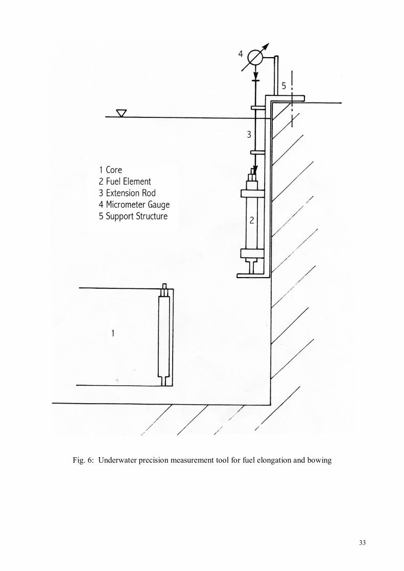
shielding is provided, however criticality alarm systems are generally required when reactor fuel is stored in a configuration that is not underwater. 9. UNDERWATER PRECISION MEASUREMENT TOOL FOR FUEL ELONGATION AND BOWING MEASURMENT It is necessary to measure the fuel element elongation and bowing regularly, for TRIGA fuel, especially in pulsing TRIGA reactors. Fuel element elongation may cause stretching or stress to the fuel cladding increasing the probability of failure. A bowed or bent element may be difficult to insert or remove from the reactor grid plates. Bowing and elongation are a direct function of fuel element burnup and temperature gradient. Occasional rotation or in-core translocation may reduce the affects of non-uniform reactor power distributions. The maximum elongation allowed by the fuel supplier is 6.25 mm for aluminium clad fuel and for stainless steel clad fuel the limit is 2.54 mm. Typically, it is recommended to inspect the fuel every two years or after 50 reactivity pulses of $2.00 or more. More frequent inspections may be required but a complete core inspection should be performed if any element is found to be out of specification in between scheduled inspections. The fuel measuring process starts with removing one element from the core and placing it into the underwater measuring tool. Several variations of measurement tools exist and General Atomics provides one version of a tool. The important concept of elongation measurement is that the current fuel element length is compared to a known standard length. Some facilities have a non- fuelled element calibration standard of a nominal “as built” fuel element length. The difference between the element length and the standard will determine the actually length on the date of measurement. This value is compared to previous measurement to produce an elongation measurement. Clearly, the process must begin with a very good measurement of the new element as a starting point of 0.0 mm elongation. The elongation data are then evaluated and any fuel exceeding the elongation limit is removed from the core. Bow measurements are much simpler and may indicate if an element is nearing the failure stage. Bow is effectively the curvature or bending of an element. This is sometimes caused by an uneven fuel burnup when one side of the element is facing a flux trap or water hole. Bow is measured using a so-called “go, no-go” gauge. Effectively, this is a straight pipe or tube with the inside diameter only slightly (<1mm) greater than the diameter of a new element. If the element is perfectly straight, it will slide into the tube with no resistance (“go”). If the element is bowed or bent, it will bind as the element is passed through the tube (“no go”). The bow measurement will also detect early signs of fuel failure caused by bulging or localized swelling the fuel. 10. FUEL TRANSFER CASK AND SPENT FUEL INSPECTION CONTAINER For the transfer of a spent fuel element from the reactor tank to the spent fuel storage or the spent fuel inspection container a spent fuel transfer cask is used, its cross section is shown in Fig. 9. A typical design consists of a heavy lead container (i.e. 1500 kg) suspended on the overhead crane, then the cask is lowered into the reactor tank and the spent fuel element is pulled with the handling tool into the transfer cask. The bottom shutter is closed and the security lock is activated. Hereafter the fuel element can either be transferred to the spent fuel storage or to the spent fuel inspection container. Unless an emergency transfer is required, the fuel element is stored in the reactor tank for about 6 to 8 weeks for decay of the fission products and activated cladding materials.

17
The spent fuel inspection container (see Fig. 10) allows either a visual inspection of the fuel cladding using an endoscope (Fig. 11) or a measurement of the distribution of fission products along the axis of the fuel element by gamma spectroscopy . In this case of fission product distribution, a HPGe detector is placed in front of a radial collimator hole looking at the fuel element axis (see Fig. 10). By lifting the fuel element along its axis in front of the collimator a step wise gamma profile can be measured (Fig. 12). 11. REACTOR PROTECTION SYSTEM (RPS) In order to operate a reactor, many variables have to be measured and monitored. Some of them are considered to be vital for the safety of the reactor, and their measurement has to be fast and reliable. What follows is a description of the technological options actually used to measure, process, display and record the variables in research reactors. 11.1 Nuclear Instrumentation In research reactors the neutron flux has to be monitored from a low level to maximum power level. The detected flux is normally subdivided into three intervals, source range (below 104 nv, equivalent to 10-3 percent of nominal power), intermediate range (from 103 to 109 nv, or 10-4 to 102 percent of nominal power), and power range (from 107 to 2×10⁹ nv, or 1 to 200 percent of nominal power) as shown in Tab. 1. In the source range interval, due to the low rate of events occurring within the detector, pulse counting mode is traditionally used, whereas the current mode is adopted in the intermediate and power range intervals. The following equipment is currently available for detection and measurement of the neutron flux in the above three intervals.
Neutron flux at the core
Neutron flux at the start-up channel
source range position
Neutron flux at the start-up channel
inter-mediate range position
Neutron flux at the power channel
position
Neutron flux at the wide range
linear channel position
10E14 10E14 10E14 10E13 10E13 10E13 10E12 10E12 10E12 10E11 10E11 10E11 10E10 10E10 10E10 10E09 10E09 10E09 10E09 10E08 10E08 10E08 10E08 10E07 10E07 10E07 10E06 10E06 10E06 10E05 10E05 10E05 10E05 10E04 10E04 10E04 10E04 10E03 10E03 10E02 10E02 10E01 10E01 10E00 10E00
Tab. 1: Neutron flux measuring ranges

18
11.1.1 Neutron Detectors The main reason to monitor neutron flux in a reactor is that it is proportional to the power density, and this is the variable, which we are concerned about. There are mainly five types of neutron detectors, BF3 proportional counters, boron (10B) lined detectors, fission chambers, 3He proportional counters, and self-powered neutron detectors. Two other instruments are widely used to monitor the reactor power, calorimeters, used to monitor power density, and N16 detectors used to monitor integral reactor power. Detectors are usually located in fixed positions about or around the reactor core, and the quantity measured is often the leakage flux, i.e., the flux exterior to the core. The detector shall be placed in instrument ports that are leak-tight so that they will not be subjected to moisture. A purge of inert gas in these ports is also often provided in order to prevent the build-up of corrosive substances. Since detectors are located in intense gamma-ray fields, which may degrade cable insulation, mineral insulators with integral-lead detectors are preferred. These cables are procured at the time the detector is ordered, and must be sized for length at that time. lf the detector is sensitive enough, it is recommended to place it as far as possible from the core. This will reduce radiation hazard to the detector, and also limit the effect of gamma-induced current. In general, neutron and radiation detectors may be designed for any of three modes of operation: current mode, pulse mode and mean square voltage (MSV) mode. The latter is also called "Campbelling" mode (named for the Campbell Theorem). In any detector the incident radiation is converted to electric charge. The three modes of operation refer to the manner in which this charge is collected and processed. The mode of operation of a particular system depends on the specific design of the detector and its external electronics. • Current mode: A current measuring circuit is placed across the terminals of the detector,
and the average current is measured by the system. Current mode operation is the most common operation mode. It is used for measuring the power of the reactor and also in most portable survey meters.
• Pulse mode: An RC circuit is placed across the terminals of the detector and the voltage
produced in the circuit is measured. Pulse mode is used in a research reactor mainly during start-up because it provides spectral information used to distinguish between neutrons and gamma radiation. Pulse mode detectors are also useful in criticality experiments in which it is desirable to plot the inverse counts versus the mass of 235U in the core.
• MSV or Campbelling mode: The output of the current mode operation is a varying current,
which can be regarded as a sum of a steady-state component and a time varying component. The MSV circuit blocks the steady-state component and squares the amplitude of the varying component. The resulting signal is proportional to the square of the charge that is created by each incident particle of radiation, thus enhancing the difference between types of radiation. MSV mode is used primarily for nuclear reactor instrumentation as a mean of measuring neutrons in high gamma background. Campbell instrumentation may be used to measure the neutron flux in a reactor from source range to power range with a single channel.

19
Since insertion and withdrawal of control rods on top of the core changes the shape of the neutron flux, care must be taken in selecting the right position for the neutron detectors. Periodic calibration and cross checking of neutron detectors is highly recommended. 11.1.2 BF3 proportional counters are highly sensitive to neutrons, and are usually used in a pulse counting mode to monitor the neutron flux and the reactor period (rate at which the neutron flux changes) in the source (start-up) range. Even it is not usual, BF3 detectors can also be used as compensated ionisation chambers, to monitor the neutron flux level and the reactor period in the intermediate range. BF3 counters are not generally used for high reactor application as BF3 is a very aggressive gas and dissociates under radiation.
Fig. 11: BF3 proportional counters
11.1.3 Boron (10B) lined detectors (Fig. 11) are used in both, pulse counting mode (as counters) and DC current mode (as ionisation chambers). As counters, they are used in the source range, and as ionisation chambers they may be used either as intermediate or as power range detectors. When used in the intermediate range they are usually gamma compensated ionisation chambers, and when used in the power range they are uncompensated ionisation chambers. The principle of an ionisation chamber consists in collecting electrical charges released in the chamber gas without causing gas multiplication. An ionisation chamber consists of two or more concentric electrodes whose surfaces are coated with a neutron sensitive material such as 10B or 235U. A gaseous mixture between the electrodes enables the electrical charges to be developed, the collection of these charges will produce the signal. The gas is usually a neutral gas such as argon or nitrogen. In the particular case of fission chambers, nitrogen (N2) is added to the gas in order to increase the electronic mobility and thus improve the chambers performance. Two types of ionisation chambers exist: • Uncompensated boron-coated ionisation chamber (UIC) The UIC uses amorphous boron, a neutron sensitive material that is deposited on the surfaces of two concentric cylindrical electrodes. The external electrode is polarised at a positive voltage around +600 V, the central electrode collects the electrons produced in the gas without multiplication resulting in a DC current. The current depends on the quantity of boron on the electrodes and, therefore, on the size of the detector. The typical values of the neutron sensitivity of a UIC is between 2×10-14 A/nv for small detectors and 3×10-13 A/nv for large detectors. It is important that the chamber voltage is located in the saturation plateau, the higher the neutron flux the higher the voltage where the chamber reaches its saturation plateau

20
(Fig. 12). The chamber also has a sensitivity to gamma radiation, typical values are between 10-9 A/Gy/h for small to 10-8 A/Gy/h for large detectors.
Fig. 12: Saturation curve array
• Compensated boron-coated ionisation chamber (CIC) Generally, ex-core detectors are subjected to gamma radiation, which covers the signal produced by neutrons in the low neutron flux range. This is the case i.e. after reactor shut down or in the start-up range of the reactor. In order to improve the neutron detection and to detect low neutron fluence rates, CIC are used. A CIC is a differential chamber consisting of three concentric electrodes, which define two chambers (Fig. 13). The first chamber is located between the external positive polarization electrode and the central electrode, which collects the signal. The surfaces of the electrodes are coated with a boron deposit. It is, therefore, sensitive to neutrons and gamma rays. The second chamber is located between the internal negative polarization electrode and the signal electrode. The surfaces are not coated with boron and the chamber is, therefore, only sensitive to gamma rays. The currents of these two chambers are subtracted one from the other due to their opposite polarization and the resulting current is, therefore, only proportional to the neutron flux. The typical neutron sensitivity of a CIC is between 10-14 A/nv to 10-13 A/nv. The CIC is designed to eliminate the gamma contribution. To characterize the efficiency of the compensation, the chamber signal is plotted against the compensation voltage applied. This task is performed in a high gamma field but in the absence of neutrons. This condition is established immediately following a reactor shutdown from several hours of high power operation. The neutron level decreases at a known rate (-80 second period) immediately

21
following reactor shutdown until the neutron current stabilizes at some subcritical level. At this same period of time, a large gamma ray induced current is produced in the CIC due to the decay of the activated reactor components and fission products. The operator may evaluate if the gamma compensation is sufficient by noting if the ion current stabilizes too soon (less than 20 minutes after shutdown). Ion current levelling off too soon or at too high a level would indicate excessive uncompensated gamma induced currents and required adjustment of the compensation voltage. It should be mentioned that the compensation needed depends, among other parameters, on the energy spectrum of the incident photons. Neutron capture gamma rays are often of higher energy than radioactive decay gamma rays. Figure 14 shows a typical compensation plot showing the effects of over or under compensation.
Fig. 13: Compensated ionisation chamber diagram
Fig. 14: Typical plot of a compensation curve
22
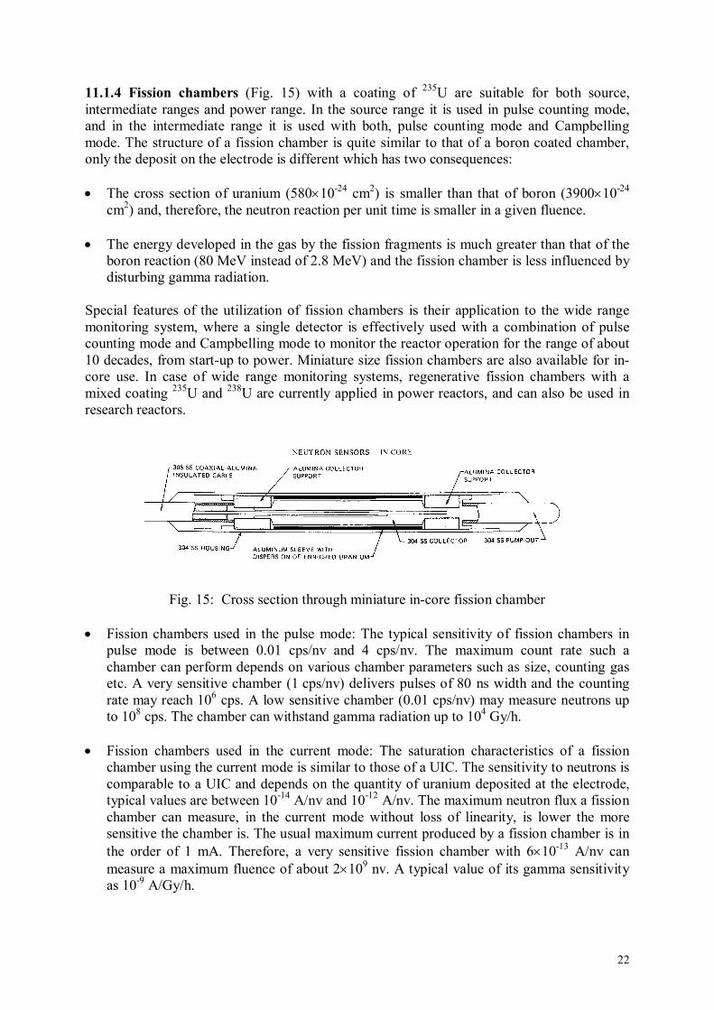
11.1.4 Fission chambers (Fig. 15) with a coating of 235U are suitable for both source, intermediate ranges and power range. In the source range it is used in pulse counting mode, and in the intermediate range it is used with both, pulse counting mode and Campbelling mode. The structure of a fission chamber is quite similar to that of a boron coated chamber, only the deposit on the electrode is different which has two consequences: • The cross section of uranium (580×10-24 cm2) is smaller than that of boron (3900×10-24
cm2) and, therefore, the neutron reaction per unit time is smaller in a given fluence. • The energy developed in the gas by the fission fragments is much greater than that of the
boron reaction (80 MeV instead of 2.8 MeV) and the fission chamber is less influenced by disturbing gamma radiation.
Special features of the utilization of fission chambers is their application to the wide range monitoring system, where a single detector is effectively used with a combination of pulse counting mode and Campbelling mode to monitor the reactor operation for the range of about 10 decades, from start-up to power. Miniature size fission chambers are also available for in-core use. In case of wide range monitoring systems, regenerative fission chambers with a mixed coating 235U and 238U are currently applied in power reactors, and can also be used in research reactors.
Fig. 15: Cross section through miniature in-core fission chamber • Fission chambers used in the pulse mode: The typical sensitivity of fission chambers in
pulse mode is between 0.01 cps/nv and 4 cps/nv. The maximum count rate such a chamber can perform depends on various chamber parameters such as size, counting gas etc. A very sensitive chamber (1 cps/nv) delivers pulses of 80 ns width and the counting rate may reach 106 cps. A low sensitive chamber (0.01 cps/nv) may measure neutrons up to 108 cps. The chamber can withstand gamma radiation up to 104 Gy/h.
• Fission chambers used in the current mode: The saturation characteristics of a fission
chamber using the current mode is similar to those of a UIC. The sensitivity to neutrons is comparable to a UIC and depends on the quantity of uranium deposited at the electrode, typical values are between 10-14 A/nv and 10-12 A/nv. The maximum neutron flux a fission chamber can measure, in the current mode without loss of linearity, is lower the more sensitive the chamber is. The usual maximum current produced by a fission chamber is in the order of 1 mA. Therefore, a very sensitive fission chamber with 6×10-13 A/nv can measure a maximum fluence of about 2×10⁹ nv. A typical value of its gamma sensitivity as 10-9 A/Gy/h.

23
• Fission chambers in the Campbelling mode: For high fluence rates, pulse detectors are limited by the pile-up phenomenon of pulses. One pulse has no time to disappear before the new pulse appears and superposes itself on the preceding one. The signal delivered by the detector is fluctuating. The electronics provided to process the pulses is not able to distinguish two successive pulses and counting loss is observed. It is, however possible to increase the operational range of the detector by using this pile-up phenomenon. The signal fluctuation is a measurement of the neutron fluence rate and this measurement is increasingly accurate the greater the energy deposit is caused by a neutron event. The important point is that the difference between the neutron signal and the gamma signal is as large as possible. Due to the high energy deposited by a neutron compared to a gamma interaction in the counting gas the fission chamber is the only detector capable of using fluctuations to create a neutron proportional signal. The Campbell theorem states that the mean square voltage of the signal fluctuation is proportional to the neutron fluence rate. To obtain this proportionality the signal, therefore, has to be squared. Unlike pulses or currents, which give the required value directly, the neutron fluence rate is obtained by calculation.
11.2 Reactor protection and power regulating system The nuclear instrumentation comprises the neutron flux instrumentation and a nitrogen-16 gamma channel. Neutron flux measurement instrumentation supplies information on physical parameters to the reactor protection system and the reactor power regulating system, describing the state of the reactor regarding neutron production and its evolution. The neutron flux measurement system comprises three independent measuring channels based on fission counters, a wide range fission chamber and compensated ionisation chambers, which are able to keep track of neutron flux for the whole operation range of the reactor. There is an overlap between the channels, as well as an adequate margin over full power (FP) for the follow-up of eventual power excursion. The reactor protection system (RPS) includes two separate channels to cover the neutron excursion over the whole operation range of the reactor (from source level to 125% of full power level). These channels are: • Start-up channel • Power channel In order to comply with safety and reliability requirements, each channel type of the reactor protection system (start-up channel and power channel) is constituted of redundant channels entirely independent of the detector up to the electronic measuring modules. Under normal conditions the reactor protection system operates with the required redundancy. Should a failure occur in one channel, the resulting signal at the end of the channel is coincidental with the corresponding signal requiring a protective action in order to reduce, as much as possible, the required coincidence over the rest of the system ("fail safe" criteria). The reactor power regulating system (RPRS) controls reactor power from source level to 125% of full power level, using neutron and gamma instrumentation • Wide range linear channel • 16N linear channel.

24
11.3 A Typical TRIGA Instrumentation and Control (I&C) System 11.3.1 System Design The typical TRIGA Instrumentation and Control Systems (the console) have evolved from electronic tube type instrumentation in the early sixties to transistorised instrumentation in the seventies to a computerized instrumentation in the early nineties. Unfortunately, as technology moved forward, many older TRIGA facilities were unable to obtain spare or replacement parts for their reactor consoles from the original suppliers. Some facilities, i.e. those with an electronics support staff, have been able to build or replace console components with equivalent or near-equivalent equipment. The replacement systems currently available from General Atomics are fully digital, computerized reactor consoles. Many of the digital systems have equivalent analog components in use at other facilities but the information below is generally focused on the newer, digital consoles. The main system of the new instrumentation is a wide range channel (NM-1000), which operates at low power in the pulse mode and at higher power in the Campbell mode. From this channel important parameters are extracted and displayed on a colour graphic screen, such as: linear power, log power, period, count rate, percent power. In this channel a microprocessor is involved using a specially developed software which practically cannot be verified. As a redundant safety channel, GA offered one percent power channel (NP-1000), which creates a hard-wired shut down signal at nominal power plus 10%. This means that only one hard-wired safety channel was available in the proposed system. This design is unacceptable according to European standards and had to be modified. The modified system design is displayed in Fig. 13. Besides the NM-1000 channel, which is considered only as an operational channel without safety relevance, two identical hard-wired linear channels (NMP-1, NMP-2) have been installed. Both channels are constantly compared and any discrepancy exceeding 10% trigger an alarm. Further, both channels are switched together by a range switch, resulting in a reactor scram signal in each range at 10% overpower. In addition, two strip chart recorders for linear power and for fuel temperature recording during pulse operation are provided. The reactor is controlled by four nuclear channels, their signals are displayed both at a colour graphic-monitor and at bar graph indicators . a) The auto-ranging wide-range channel NM-1000 controls the reactor power from the
source level (around 5 mW) up to nominal power of 250 kW. It uses a Campbell fission chamber and the signal is controlled by a microprocessor.
b) Two independent linear channels, NMP-Ch and NMP-Ph control the reactor power from
the source level up to nominal power. The signals pass over a range switch, which selects the power range. If the signal on one of these two channels exceeds the selected power range for more than 5%, the reactor is shut down automatically. Both channels use compensated ionisation chambers as sensors.
c) For the control of reactor pulse operation an uncompensated ionisation chamber NPP-
1000 is used. This chamber measures the shape of the reactor pulse, which is displayed on the graphic monitor. Further pulse data, like integrated power, are calculated from this signal

25
Table 2 lists the different scram parameters for a typical 250 kW TRIGA Mark II reactor: Scram - Fuel Temp Hi Thermocouple one till six 350°C
Scram - NPP-1000 Hi Voltage Lo 700 V Scram - NMP-CH Hi Voltage Lo 700 V Scram - NMP-Ph Hi Voltage Lo 700 V Scram - NPP-1000 nvt Hi 12 MWs Scram - NM-1000 % Power Hi 110% Scram - NMP-Ph % Power Hi 110% Scram - NMP-Ch % Power Hi 110% Scram - NM-1000 (Reactor period short) 3s Scram - CSC Time out Scram - CSC Fault Scram - DAC Time out Scram - DAC Fault Scram - Service air Scram - Poll Level extremely low # 1 -1 m Scram - Poll Level extremely low # 2 -1 m Scram - Pool Temperature 40°C Scram - Outlet Temperature 40°C Scram - Console Manual Scram - Please Log In Scram - Key Switch Off Scram - Net Fault, Please Reboot Scram - CSC DIS064 Timeout Scram - DAC DIS064 Timeout Scram - Data Base Timeout Scram - NM-1000 Comm Fault Scram - NM-1000 Data Error Scram 220V
Tab. 2: Scram parameters for a typical TRIGA Mark II
11.4 Operational experience with Digital Instrumentation and Control Systems The digital instrumentation design originates from the mid-eighties and most of the electronic equipment, especially the CSC computer and the DAC computer, was already outdated at the time of installation. Due to the rapid development in data acquisition and computer technologies, the problem of spare parts availability and compatibility became significant. However with careful planning and the cooperation of the original vendors, many problems have been solved recently by upgrading equipment and software. The present instrumentation design fulfils both, the requirements of the national authorities and a university training reactor to be used mainly in academic education. The rapid development in electronics and data acquisition accelerates design ageing of the system, but it is also a challenge to keep the system in good and state-of-the-art condition.
• Generally the operation experience is good with about 2 weeks of operation loss per year due to instrumentation problems
• Trouble shooting is much more difficult as failures can both occur in hardware and software

26
• Software is almost inaccessible for the user and can only be handled with close cooperation of the provider
• Many of the electronic instruments can only be purchased through the single original provider which may easily overcharge
• All hardware is sensitive to temperature, humidity and lightning; therefore, for tropical countries or developing countries the computerized instrumentation is not recommended

27
FIGURES Figure Title Page 1 Schematic diagram of the primary cooling system of a TRIGA reactor 28 2 Schematic diagram of a TRIGA with forced convection cooling 29 3 Schematic diagram of the secondary cooling system of a TRIGA reactor 30 4 Schematic diagram of the secondary cooling system of a 3 MW TRIGA 31 5 Fresh and fuel storage pits in the reactor hall 32 6 Underwater precision measurement tool for fuel elongation and bowing 33 7 Cross section of the fuel transfer container, weight about 1 500 kg 34 8 Experimental set-up for gamma spectroscopy of spent fuel elements 35 9 Optical pathway to view spent fuel elements 36 10 Axial Cs-137 distribution of a spent fuel TRIGA fuel element 37 11 BF3 proportional counters 19 12 Saturation curve array 20 13 Compensated ionisation chamber diagram 21 14 Typical plot of a compensation curve 21 15 Cross section through miniature in-core fission chamber 22

28
Fig.1: Schematic diagram of the primary cooling system of a TRIGA reactor

29
Fig.2: Schematic diagram of a TRIGA with forced convection cooling

30
Fig. 3: Schematic diagram of the secondary cooling system of a TRIGA reactor

31
Fig. 4: Schematic diagram of the secondary cooling system of a 3 MW TRIGA

32
Fig. 5: Fresh and fuel storage pits in the reactor hall
33
Fig. 6: Underwater precision measurement tool for fuel elongation and bowing

34
Fig 7: Cross section of the fue transfer container, weight about 1 500 kg

Fig. 8: Experimental set-up for gamma spectroscopy of spent fuel elements

36
Lead Container
Fuel Element
90° Deflection
90° Deflection
Endoscope
Figure 9: Optical pathway to view spent fuel elements

37
Fig. 10: Axial Cs-137 distribution of a spent fuel TRIGA fuel element


![The NUSTAR project at FAIR · the prototype TRIGA-SPEC[24], in operation at the TRIGA research reactor in Mainz. Figure 2. Part of the NeuLAND detector being assembled for beam tests](https://static.fdocuments.net/doc/165x107/5f96d56c9211b330077062c4/the-nustar-project-at-fair-the-prototype-triga-spec24-in-operation-at-the-triga.jpg)