Traffic Flow Theory-1 - Caltrans - California Department ...€¦ · A Practical Introduction to...
24
A Practical Introduction to Traffic Flow Theory and On-ramp Flow Control Anush Badii California Department of Transportation District 11 – San Diego
Transcript of Traffic Flow Theory-1 - Caltrans - California Department ...€¦ · A Practical Introduction to...

A Practical Introduction to
Traffic Flow Theory and On-ramp Flow
Control
Anush Badii
California Department of Transportation
District 11 – San Diego

2
Table of Contents
Introduction ..................................................................................................................................... 3
Traffic Flow Theory ........................................................................................................................ 4
Kinematic Waves Model of Traffic Flow ....................................................................................... 8
Mathematical Solution to Kinematic Waves ................................................................................ 11
Practical Traffic Engineering Applications .................................................................................. 14
Merging Traffic ......................................................................................................................... 16
Dropped Lane or Lane Convergence and Bottlenecks .............................................................. 17
Traffic Management and the Inverse Functions ........................................................................... 19
Variable Speed Policy ................................................................................................................... 22
Conclusion .................................................................................................................................... 24
Table of Figures
Figure 1 ........................................................................................................................................... 4
Figure 2 – Fundamental traffic Diagram ........................................................................................ 6
Figure 3 ........................................................................................................................................... 7
Figure 4 ......................................................................................................................................... 11
Figure 5 ......................................................................................................................................... 13
Figure 6 ......................................................................................................................................... 22

3
Introduction
In August of 2014, the Transportation Research Board (TRB) Committee on Traffic Flow
Theory and Characteristics held a symposium celebrating 50 Years of Traffic Flow Theory in the
Midyear Meeting in Portland, Oregon, USA. The predecessor committee focusing on traffic flow
theory was organized 50 years ago, to recognize the past accomplishments in the field, reflecting
on the present state of our research community and identifying key future directions.
The fact of the matter was that this meeting, like other similar meetings, did not advance the
science first proposed by Greeshield in 1930s, and since then a myriad of academics and
professionals have expounded on his seminal work and offered as many traffic flow theories and
conjectures. These theories, despite their mathematical elegance are mostly inaccurate, as their
progenitors had paid no heed to Leibniz’s warning that utilizing his mathematical notation
always leads to self-consistent but not necessarily accurate results.
In this book we will not attempt to present any of these theories other than what is needed in the
minimum for the reader to gain a complete understanding of the traffic flow.
As far as this author is concerned the traffic theory has had three major contributions since
Greenshield’s original effort. In 1953 Lighthill and Whitman followed by Roberts introduced the
LWR model without the required extension into the synchronous traffic movement. In 1964
Newell proposed his model of Fundamental Traffic Diagram without successfully deriving the
slope of the downward portion of diagram that corresponds to congested traffic. The unification
of LWR and Newell is the hinge pin of understanding the traffic flow and its management as it
would be required by the increasing number of vehicles worldwide and the inability of the
governments to keep up with the construction of the infrastructure required to support the
number of vehicles being used.

4
Traffic Flow Theory
The most important concept in traffic flow is that of density. The vehicular density is measured
in number of vehicles per mile, but in actual engineering practice one does not need to count the
number of vehicles in one mile, the distance between two consecutive vehicles suffices to
determine density.
� = 5280� +
The above equation simply describes the number of vehicles and the distance in front of them
that fit inside a mile. We represent that as � and call it vehicular density – 5280 represents the
number of feet in one mile, � is the typical vehicular length and the distance between two
consecutive vehicles.
It is important for the reader to realize that in the course of one mile one may encounter several
pockets of different vehicular densities, for example two consecutive stop lights may create two
pockets of very high density with scant vehicular density in between, the same may be imagined
on a roadway where one might encounter vehicles moving in packets of different densities.
Solving for and dividing by the speed � we may arrive at an equation for the time of impact�,
if the vehicle ahead would come to sudden stop.
� = � =
5280 − ����
For standard vehicular length of 14.75 ft the Distance versus Density is plotted in Figure 1.
Figure 1
Conversely, we may also write an equation for speed in miles per hour

5
� = 5280 − �����̅
Where � ̅is �������� the conversion factor from ft/sec to MPH.
For ordinary traffic situations, the drivers normally abide by the posted speed limit, therefore we
may presume � to be a constant �� . We may thus calculate the hourly volume flow of vehicles� as
� = ���
It becomes obvious that the time of impact will become increasingly shorter with the increased
density until the density reaches a point that the driver chooses to sacrifice the speed in favor of a
safe time of impact ��, and we may say that at that point we have reached a critical density ��.
Careful measurements of �� in various regions have shown that �� varies from region to region
but it is regionally stable. In southern California �� is measured to be 1.75 seconds and in Seoul,
Korea it is measured at 2.5 seconds. The speed required to maintain a safe time of impact is then:
� = 5280 − ������̅
We may compute �� from the intersection of the line � = ���with
� = �� = � 5280 − ������̅
Solving for � we get an expression for��
�� = 5280� + �����̅
This derivation is universal and applies to vehicular traffic (cars, bicycles, etc.) or even
pedestrians and movement of ants. The results of a wonderful graphic experiment can be found
at (http://tft.ceng.calpoly.edu/tft50/tft50_papers/P08_Seyfried.pdf).
As such �� becomes a dividing point to bifurcate the traffic flow into two regions of free flow
and synchronized flow, a plot of which is presented in Figure 2.

6
Figure 2 – Fundamental traffic Diagram
The diagram was first proposed by Newell in 1964 and was derived by this author in 2012. What
is noteworthy in this diagram is the downward slope of diagram that is computed to be− ��� .
Rewriting the equation for flow when � > �� as
� = �� = � 5280 − ������̅ = 5280
���̅ −�����̅
We define the first term as total capacity�� !of the freeway
�� ! = 5280���̅
And the flow that is not getting through or backing up as
"# �$%&'( = ���̅��
Such that the observed flow
�� )*�%�+ = �� ! − "# �$%&'(
And the observed speed will be
�� )*�%�+ = �� )*�%�+�
It is noteworthy that in a situation like NASCAR where �� is measured in milliseconds the
observed flow will be more than 20,000 vehicles/hour.
Also we need to mention that for � = �� there is a residual back up flow of ,)-����̅ .
A plot of backed up flow and manifest flow is presented below (Figure 3) as a function of
density.

7
Figure 3
The reader may be surprised by the terminology we adopted for which we need to introduce the
Kinematic Waves Theory of Traffic Flow.

8
Kinematic Waves Model of Traffic Flow
The kinematic waves theory was seminally proposed by Lighthill and Witham (1955) while
studying the tidal backflow into the mouth of river Thames, and later on independently by
Roberts in 1956 as a fluid model for traffic flow now known as LW R kinematic waves model.
The central postulate of the theory is that there exists a relationship between the flow and the
density such that
.�
./ + � .�.0 = 0
The derivation of the above equation is fairly straight forward through the application of first
principles of calculus. Here we will repeat the derivation and then extend it to cover both flow
regimes of traffic.
The variation of number of vehicles N in the system between two measuring stations A at
upstream and B at downstream with time may be written as
12(0)10 = "5(6, 0) − "8(9, 0)
On the other hand we may express N in terms of density
2(0) = : �(/, 0)1058
Substituting
12(0)10 = 1
10 : �(/, 0)1058
= "5(6, 0) − "8(9, 0) By Leibniz axiom we may write as "5(6, 0) − "8(9, 0) as
: ../ "(/, 0)1/
5
8
Substituting
110: �(/, 0)105
8= : .
./ "(/, 0)1/5
8
Dropping the integrals, we may write the above as
.�(/, 0).0 − ."(/, 0)
./ = 0

9
But "(/, 0) = �(/, 0)�(�) with � itself having dependence on �, i.e., � = �(�(/, 0)) .�(/, 0).0 − �(�) .�(/, 0)./ − �(/, 0) .�(�)./ = 0
Expanding the last term
.�(/, 0).0 − �(�) .�(/, 0)./ − �(/, 0) .�(�).�
.�(/, 0)./ = 0
Substituting
�(�) = ;</ =�� , 5280 − ��>%?�� @ And
.�(�).� = ;A� B0, 5280��� C
Applying the two flow regime concepts
.�
.� = 0<�1� = ��∀� < �� We end up with a wave equation of the form
.�(/, 0).0 − F��G.�(/, 0)./ = 0∀� < ��
Which describes a density wave travelling in forward direction with the speed F��G And as for the case where
� = 5280 − ��>%?�� ∀� > �� We may write
.�
.0 − B5280 − ��>%?�� − 5280��� �C .�./ = 0
Leading to
.�(/, 0).0 + H��Iℎ� K.�(/, 0)./ = 0∀� > ��

10
Which describes a wave travelling at speed of L��Iℎ� Mbackward, consistent with observations of
scientists at the Nagoya University in Japan [http://iopscience.iop.org/1367-
2630/15/10/103034/article]
The appearance of L��Iℎ� M unifies the Newell model with LWR fluid model.
Additionally the use of the backed up flow is justified in our previous discussion. The
phenomenon is observed daily and has been called the phantom wave by some.

11
Mathematical Solution to Kinematic Waves
The solution to the Kinematic wave equations introduced in previous chapter is any arbitrary
function of the form�(/, 0) = N(</ + O�0). However we need to choose our function carefully. Fully knowing that the expected solution is a
wave,
By examination the wave length is � + and wave number (number of waves in a period) is �����PQ which is the density
Figure 4
Thus we may write
N(/, 0) = 5280/� + + 5280�0
� +
N(/, 0) = �(/ + �0)
Recognizing the product of ��� = � (��ARSTU), similarly the product of ��� � = �̅", we write
the solution to the first and the second differential equation as:
�/ + �0∀� < �� And
�/ − �̅"0∀� > �� Where the first term describes the shape density shape and second term describes transport of it1.
The above equations simply define the argument of the wave function. To construct the function
itself we may write a Heaviside boxcar function ℶ(/) represented by the Hebrew letter beth with

12
the above argument to represent a group of vehicles with a given speed and density. The number
of vehicles in the group N is the length defined by the multiples of L+D such that
|(/% − /#| = 2(� + ) ℶ(/, �, 0) = [U(�Y/ − /# − ��0Z) − U(�Y/ − /% − ��0Z)]
The above function represents a rectangular shape starting at /# and ending at /% travelling at ��
Transporting the density n and the flow rate � =���
To test the validity of the above function, first we take the derivative of it with respect to time t
and with respect to distance x
.ℶ(/, �, 0)./ = �\(�Y/ − /# − ��0)Z − �\(�(/ − /% − ��0))
And
.ℶ(/, �, 0).0 = −���\(�Y/ − /# − ��0)Z + ���\(�(/ − /% − ��0))
Adding the two together
.ℶ(/, �, 0)./ + �� .ℶ(/, �, 0).0 = 0(�. ]. )
The number of vehicles that are accumulated in the backup in the time 0 �� is then
"0 ��3600
And the time it will take to disperse the accumulated backed up traffic is then
0&*�(%`��*a) = "0 ��3600 �
As expected the time of dispersion is longer than the time of accumulation by the factor of �.
To construct the Heaviside function one may employ the sign function Rb�(/) Where Rb�(/)is the sign function defined as
Rb�(/) = /|/|∀/ ≠ 0
ℶ(/) = 12 [Rb�(/ + <) − Rb�(/ − O)]

13
Then one can make it travel to the right
ℶ(/) = 12 [Rb�(/ + < − �0) − Rb�(/ − O − �0)]
We have formed a box car function representing 4 vehicles with the density of 30 vehicles per
mile in Figure 5.
We have formed a box car function representing 4 vehicles with the density of 30 vehicles per
mile in Figure 5.
Figure 5
To combine two separate densities one may need to employ the “Exclusive Or” function.

14
Practical Traffic Engineering Applications
The practitioners of traffic engineering are more likely interested to solve ordinary day to day
traffic engineering problems. Looking at Figure 5 it is easy to imagine how two streams of traffic
merge with each other as if each vehicle was a tooth on a zipper. We may at this point debunk all
traffic engineering manuals, books and papers prescribing flow additions and affirm that flows
are not additive and that only density is additive, while simultaneously take advantage of the
constancy of τf and provide a new method to compute the state equation for traffic flow.
Although traffic waves travelling forward and backward are interesting as a phenomenon, we can
take advantage of the constancy of impact time and present a new and comprehensive
methodology for practitioners of traffic engineering who deal on day to day basis with
congestion.
Suppose the traffic undergoes a state change from state g9h with density � and speed � to state g6h with density �#and speed �#
If �# < ��thecriticaldensity, then �# =�� , however if �# > �� Then the inter-vehicular distance for state g9h may be computed as
= 5280 − � ��
Similarly
# = 5280 − �#��#
�� = � =#�#
Eliminating �� from the above equations, we may write
�# = � �u
And the flow will be
�# = �)�#

15
We may also take advantage of our findings and solve the equation for merging traffic, as well as
the added or dropped lanes. See the next section.

16
Merging Traffic
An on-ramp traffic is merged with the outermost lane. Merging occurs at the speed of the
outermost lane with qw representing on-ramp volume, qu and vu representing volume and speed
on the outermost freeway lane.
The density of the outermost lane can be calculated as
�u = "u�u The inter vehicular distance in the outermost lane is
u = 5280 − �u�>%?�u
The density of the ramp is
�` = "`�u The total density at the merge is then
��%`y = �u + �`
When nz{w| > n} one may compute the inter vehicular distance at merging point
�%`y = 5280 − ��%`y�>%?��%`y The speed after merging
��%`y = �u �%`yu The flow after merging
"�%`y = (�u + �`)��%`y = ��%`y��%`y
Similarly the problem of contraction or expansion in the number of lanes may be addressed.

17
Dropped Lane or Lane Convergence and Bottlenecks
Let N� and N� represent the number of lanes upstream and downstream for a section of the
highway. The resulting density after the transition
�& = 2'2& �' Wheren� and n� are downstream density and upstream density values.
When �& > �� one may compute the inter vehicular distance at merging point as
& = 5280 − �&�>%?�& And downstream speed as
�& = �' &'
Then the downstream flow
"& = �&�& The traffic engineering practitioners may be more interested in calculating the time of congestion
building. The differential flow rate at any segment
1� = Y"'(�+`% � − "&a�)�+`% �Z And the differential density
1� = Y�'(�+`% � − �&a�)�+`% �Z Realizing that
1�1� = ��∀�&a�)�+`% � < �� 1�1� = −�� ∀�&a�)�+`% � > ��
Therefore when �&a�)�+`% � < �� then there is no back propagation of vehicles, however when
�&a�)�+`% � > �� the vehicles back propagate at the rate of �� feet per second or about 5.75
MPH regardless of the density.

18
The number of vehicles affected by back propagation per hour is then
2 = 5280 × 5.75� + &

19
Traffic Management and the Inverse Functions
The practitioners of traffic engineering may be more interested to discover how they can
influence the outcome of traffic flow through management of access to the on-ramps. To
accomplish this one needs to predicate on the control of one of the traffic flow variables.
The traffic engineering practitioner may choose to control the density, flow volume, or the queue
on the ramp. In the following discussions we have provided a prescription for control of these
variables via the inverse functions.
��%`y% = �` �( + �'(�+`% �
Substituting for their values
��%`y% = "` �(�'(�+`% � + �'(�+`% ��'(�+`% �
The merge density of the traffic on the main lanes after a flow from the ramp to an2 lane
facility is
��%`y% = "` �(2�'(�+`% � + �'(�+`% ��'(�+`% � If controlling the density is a goal we utilize the above equation by asserting ��%`y% = �ya �
�ya � = "` �(2�'(�+`% � + �'(�+`% ��'(�+`% � "` �( = 2Y�ya ��'(�+`% � − �'(�+`% �Z
Where 2 is the number of the main lanes. A negative value describes a flow rate that needs to be
redirected out of freeway to accomplish the goal. As such predicating on density is not a good
choice for traffic control since we have no control over the number of vehicles that need to be
redirected out of the system.
A better choice to maintain a sustainable flow gradient to optimize travel time is the control of
flow on the main lanes for a sustainable flow gradient. The derivation is tedious but straight
forward.
The speed of the merge may be described by the equation of merge
��%`y% = �'(�+`% � �%`y%'(�+`% �
We may rewrite the above in terms of respective density
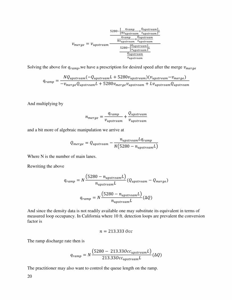
20
��%`y% = �'(�+`% �����,B �����
����������P������������������ C�
���������������P
������������������
����,B������������������ C�������������������
Solving the above for "` �(,we have a prescription for desired speed after the merge ��%`y%
"` �( = 2�'(�+`% �(−�'(�+`% �� + 5280�'(�+`% �)(�'(�+`% �−��%`y%)−��%`y%�'(�+`% �� + 5280��%`y%�'(�+`% � + ��'(�+`% ��'(�+`% �
And multiplying by
��%`y% = "` �(�'(�+`% � + �'(�+`% ��'(�+`% �
and a bit more of algebraic manipulation we arrive at
��%`y% = �'(�+`% � − �'(�+`% ��"` �(2Y5280 − �'(�+`% ��Z
Where N is the number of main lanes.
Rewriting the above
"` �( = 2 Y5280 − �'(�+`% ��Z�'(�+`% �� (�'(�+`% � − ��%`y%)
"` �( = 2 Y5280 − �'(�+`% ��Z�'(�+`% �� (∆�) And since the density data is not readily available one may substitute its equivalent in terms of
measured loop occupancy. In California where 10 ft. detection loops are prevalent the conversion
factor is
� = 213.333���
The ramp discharge rate then is
"` �( = 2 Y5280 −213.33���'(�+`% ��Z213.33���'(�+`% �� (∆�) The practitioner may also want to control the queue length on the ramp.

21
The queue on the on-ramp has to be controlled for efficient operation of the corridor and to
minimize the impact of the ramp backup on the local streets. This is achieved by modulating the
queue build-up rate in response to the rate of arrival �*).
1" = �a'+ − �*)
The number of vehicles on the ramp at any time t
1"0 = (�a'+ − �*))0 + \!
Where \! is the number of vehicles on the ramp before the start of measurement.
Total vehicle length on the ramp
�>%?(�a'+ − �*))0 + \!�>%?
Percentage�a�� of ramp capacity occupied
�>%?(�a'+ − �*))0 + \!�>%?�` �( = �a�� Where Lramp is the total length of all lanes on the ramp.
Equating \! = 0 and solving for provides the prescription for controlling the percentage of
the ramp capacity occupied.
�a'+ = �*) − �a���` �(�>%?0 = "` �(
Equating�a'+ to "` �( we have the algorithm to sustain a flow gradient with the percentage of
the occupancy of the ramp capacity as a controlling factor and its impact at the merge point.
Some ramps may allow storage capacity to exceed physical capacity, in case of separate lanes for
ramp entrance; others may be restricted to 60%, for example. This parameter may be governed
by policies and ramp configuration.

22
Variable Speed Policy
As of late a few experiments (Georgia DOT and EC) have been conducted in support of variable
speed limit during the congestion hours. California is also considering the variable speed policy
on certain corridors.
A quick look at the graph below (Figure 6) shows that all �� regardless of the posted speed limit �� lie on the manifest flow (Synchronized flow) line described by
� = 5280���̅ −
���̅��
Figure 6
As such the posted speed plays no role in the behavior of synchronized traffic, however it allows
for higher densities at subcritical flow rates. This increase in density is accompanied by a
reduction in flow rate that may be advantageous in some situations (arterials).
However the benefit to freeway driving is dubious, one may verify that when the traffic
condition is such that one can only drive at say 10 miles per hour, it would not matter whether
the sign on the side of the road for speed limit is fixed at 65 MPH or variable at 35 MPH .
A better use of the roadside message sign will be to advise the travelers to maintain a large
distance between vehicles regardless of their speed (180 ft ) thus reducing density accompanied
by the ability to increase the speed and the flow. This modification in driver behavior appears to
be the only sustainable ( and also enforceable ) approach to traffic congestion and by all
accounts should also improve the highway safety,

23

24
Conclusion
In this paper we have derived all equations needed for complete understanding of traffic flow.
We have offered a sensible solution to the equation of kinematic waves consistent with both the
traffic flow diagram and field observation. At the same time we have presented a practical
method to compute traffic variables for everyday problems that a traffic engineer may encounter.
We have also provided a comprehensive method to control the flow from the ramp to achieve
any desired outcome. We have offered a method to estimate the time it takes for a traffic jam to
clear. Finally, we have offered a universal approach to balance ramp capacity with its daily use
and computed outflow. As a result we have debunked the commonly accepted practice of adding
flow rates as is prescribed in current traffic manuals , books and papers, and we have shown that
the variable speed limit is not of consequence in controlling the freeway flow.
We expect that the application of these innovative approaches would help with the manifest
gridlock that some urban areas are experiencing. We hope that readers will use the knowledge to
simulate their local area traffic situation and re-study the effects of applying the appropriate ramp
rates without the need for calibrating very expensive and time consuming traffic simulation
software.