Telemetry Channel Coding - ESAemits.sso.esa.int/emits-doc/ESTEC/AO6121-RD9-CCSDS101x0B6.pdf ·...
57
Consultative Committee for Space Data Systems RECOMMENDATION FOR SPACE DATA SYSTEM STANDARDS TELEMETRY CHANNEL CODING CCSDS 101.0-B-6 BLUE BOOK October 2002
Transcript of Telemetry Channel Coding - ESAemits.sso.esa.int/emits-doc/ESTEC/AO6121-RD9-CCSDS101x0B6.pdf ·...
ConsultativeCommittee for
Space Data Systems
RECOMMENDATION FOR SPACE DATA SYSTEM STANDARDS
TELEMETRY
CHANNEL CODING
CCSDS 101.0-B-6
BLUE BOOK
October 2002

DEDICATION
This document is dedicated to the memory of Mr. Warner H. Miller of NASA. Warner had been with the CCSDS since its beginning and throughout the years he was a major contributor to numerous standards for error control coding, radio frequency modulation, data architecture, and data compression. Warner was a superb technologist, a gentleman, and a friend always ready to help, especially young colleagues. Warner and his approach to work and life in general will be deeply missed by his many friends and colleagues in the CCSDS.
CCSDS RECOMMENDATION FOR TELEMETRY CHANNEL CODING
AUTHORITY
Issue: Blue Book, Issue 6
Date: October 2002
Location: Houston, Texas USA
This document has been approved for publication by the Management Council of the Consultative Committee for Space Data Systems (CCSDS) and represents the consensus technical agreement of the participating CCSDS Member Agencies. The procedure for review and authorization of CCSDS Recommendations is detailed in reference [D1], and the record of Agency participation in the authorization of this document can be obtained from the CCSDS Secretariat at the address below. This Recommendation is published and maintained by:
CCSDS Secretariat Office of Space Communication (Code M-3) National Aeronautics and Space Administration Washington, DC 20546, USA
CCSDS 101.0-B-6 i October 2002
CCSDS RECOMMENDATION FOR TELEMETRY CHANNEL CODING
STATEMENT OF INTENT The Consultative Committee for Space Data Systems (CCSDS) is an organization officially established by the management of member space Agencies. The Committee meets periodically to address data systems problems that are common to all participants, and to formulate sound technical solutions to these problems. Inasmuch as participation in the CCSDS is completely voluntary, the results of Committee actions are termed Recommendations and are not considered binding on any Agency. This Recommendation is issued by, and represents the consensus of, the CCSDS Plenary body. Agency endorsement of this Recommendation is entirely voluntary. Endorsement, however, indicates the following understandings: o Whenever an Agency establishes a CCSDS-related standard, this standard will be in
accord with the relevant Recommendation. Establishing such a standard does not preclude other provisions which an Agency may develop.
o Whenever an Agency establishes a CCSDS-related standard, the Agency will provide
other CCSDS member Agencies with the following information:
-- The standard itself. -- The anticipated date of initial operational capability. -- The anticipated duration of operational service.
o Specific service arrangements shall be made via memoranda of agreement. Neither this Recommendation nor any ensuing standard is a substitute for a memorandum of agreement.
No later than five years from its date of issuance, this Recommendation will be reviewed by the CCSDS to determine whether it should: (1) remain in effect without change; (2) be changed to reflect the impact of new technologies, new requirements, or new directions; or, (3) be retired or canceled. In those instances when a new version of a Recommendation is issued, existing CCSDS-related Agency standards and implementations are not negated or deemed to be non-CCSDS compatible. It is the responsibility of each Agency to determine when such standards or implementations are to be modified. Each Agency is, however, strongly encouraged to direct planning for its new standards and implementations towards the later version of the Recommendation.
CCSDS 101.0-B-6 ii October 2002
CCSDS RECOMMENDATION FOR TELEMETRY CHANNEL CODING
FOREWORD This document is a technical Recommendation for use in developing channel coding systems and has been prepared by the Consultative Committee for Space Data Systems (CCSDS). The telemetry channel coding concept described herein is the baseline concept for spacecraft-to-ground data communication within missions that are cross-supported between Agencies of the CCSDS. This Recommendation establishes a common framework and provides a common basis for the coding schemes used on spacecraft telemetry streams. It allows implementing organizations within each Agency to proceed coherently with the development of compatible derived Standards for the flight and ground systems that are within their cognizance. Derived Agency Standards may implement only a subset of the optional features allowed by the Recommendation and may incorporate features not addressed by the Recommendation. Through the process of normal evolution, it is expected that expansion, deletion, or modification of this document may occur. This Recommendation is therefore subject to CCSDS document management and change control procedures as defined in reference [D1]. Current versions of CCSDS documents are maintained at the CCSDS Web site:
http://www.ccsds.org/
Questions relating to the contents or status of this document should be addressed to the CCSDS Secretariat at the address indicated on page i.
CCSDS 101.0-B-6 iii October 2002

CCSDS RECOMMENDATION FOR TELEMETRY CHANNEL CODING
At time of publication, the active Member and Observer Agencies of the CCSDS were: Member Agencies
� Agenzia Spaziale Italiana (ASI)/Italy. � British National Space Centre (BNSC)/United Kingdom. � Canadian Space Agency (CSA)/Canada. � Centre National d�Etudes Spatiales (CNES)/France. � Deutsches Zentrum für Luft- und Raumfahrt e.V. (DLR)/Germany. � European Space Agency (ESA)/Europe. � Instituto Nacional de Pesquisas Espaciais (INPE)/Brazil. � National Aeronautics and Space Administration (NASA)/USA. � National Space Development Agency of Japan (NASDA)/Japan. � Russian Space Agency (RSA)/Russian Federation.
Observer Agencies
� Austrian Space Agency (ASA)/Austria. � Central Research Institute of Machine Building (TsNIIMash)/Russian Federation. � Centro Tecnico Aeroespacial (CTA)/Brazil. � Chinese Academy of Space Technology (CAST)/China. � Commonwealth Scientific and Industrial Research Organization (CSIRO)/Australia. � Communications Research Centre (CRC)/Canada. � Communications Research Laboratory (CRL)/Japan. � CSIR Satellite Applications Center (SAC)/South Africa. � Danish Space Research Institute (DSRI)/Denmark. � European Organization for the Exploitation of Meteorological Satellites
(EUMETSAT)/Europe. � European Telecommunications Satellite Organization (EUTELSAT)/Europe. � Federal Service of Scientific, Technical & Cultural Affairs (FSST&CA)/Belgium. � Hellenic National Space Committee (HNSC)/Greece. � Indian Space Research Organization (ISRO)/India. � Institute of Space and Astronautical Science (ISAS)/Japan. � Institute of Space Research (IKI)/Russian Federation. � KFKI Research Institute for Particle & Nuclear Physics (KFKI)/Hungary. � Korea Aerospace Research Institute (KARI)/Korea. � Ministry of Communications (MOC)/Israel. � National Oceanic & Atmospheric Administration (NOAA)/USA. � National Space Program Office (NSPO)/Taipei. � Space & Upper Atmosphere Research Commission/Pakistan. � Swedish Space Corporation (SSC)/Sweden. � United States Geological Survey (USGS)/USA.
CCSDS 101.0-B-6 iv October 2002
CCSDS RECOMMENDATION FOR TELEMETRY CHANNEL CODING
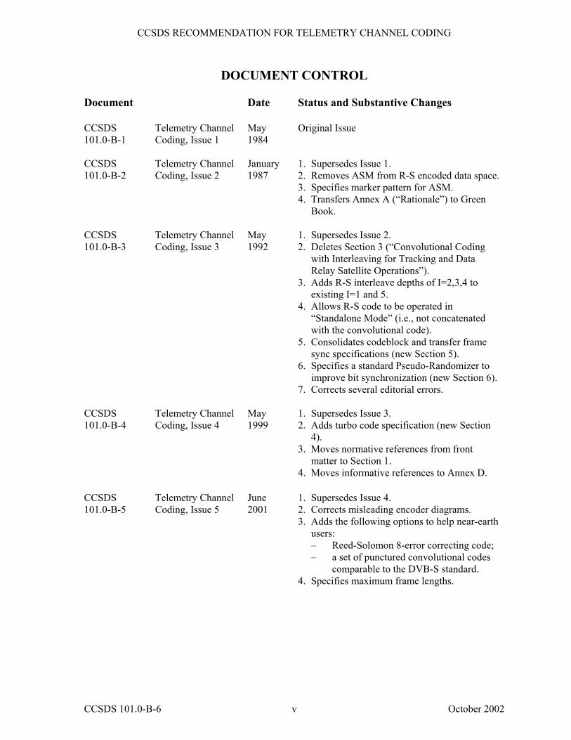
DOCUMENT CONTROL Document Date Status and Substantive Changes CCSDS 101.0-B-1
Telemetry Channel Coding, Issue 1
May 1984
Original Issue
CCSDS 101.0-B-2
Telemetry Channel Coding, Issue 2
January 1987
1. Supersedes Issue 1. 2. Removes ASM from R-S encoded data space. 3. Specifies marker pattern for ASM. 4. Transfers Annex A (�Rationale�) to Green
Book. CCSDS 101.0-B-3
Telemetry Channel Coding, Issue 3
May 1992
1. Supersedes Issue 2. 2. Deletes Section 3 (�Convolutional Coding
with Interleaving for Tracking and Data Relay Satellite Operations�).
3. Adds R-S interleave depths of I=2,3,4 to existing I=1 and 5.
4. Allows R-S code to be operated in �Standalone Mode� (i.e., not concatenated with the convolutional code).
5. Consolidates codeblock and transfer frame sync specifications (new Section 5).
6. Specifies a standard Pseudo-Randomizer to improve bit synchronization (new Section 6).
7. Corrects several editorial errors. CCSDS 101.0-B-4
Telemetry Channel Coding, Issue 4
May 1999
1. Supersedes Issue 3. 2. Adds turbo code specification (new Section
4). 3. Moves normative references from front
matter to Section 1. 4. Moves informative references to Annex D.
CCSDS 101.0-B-5
Telemetry Channel Coding, Issue 5
June 2001
1. Supersedes Issue 4. 2. Corrects misleading encoder diagrams. 3. Adds the following options to help near-earth
users: � Reed-Solomon 8-error correcting code; � a set of punctured convolutional codes
comparable to the DVB-S standard. 4. Specifies maximum frame lengths.
CCSDS 101.0-B-6 v October 2002
CCSDS RECOMMENDATION FOR TELEMETRY CHANNEL CODING
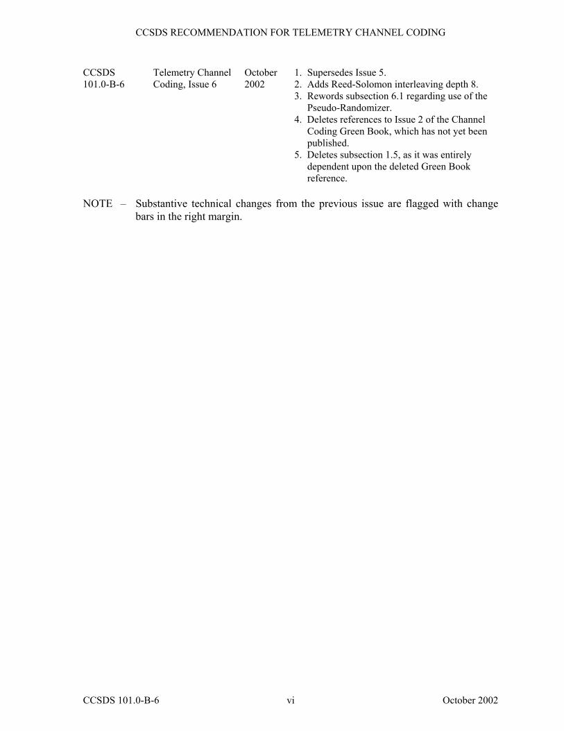
CCSDS 101.0-B-6
Telemetry Channel Coding, Issue 6
October 2002
1. Supersedes Issue 5. 2. Adds Reed-Solomon interleaving depth 8. 3. Rewords subsection 6.1 regarding use of the
Pseudo-Randomizer. 4. Deletes references to Issue 2 of the Channel
Coding Green Book, which has not yet been published.
5. Deletes subsection 1.5, as it was entirely dependent upon the deleted Green Book reference.
NOTE � Substantive technical changes from the previous issue are flagged with change
bars in the right margin.
CCSDS 101.0-B-6 vi October 2002
CCSDS RECOMMENDATION FOR TELEMETRY CHANNEL CODING
CONTENTS Section Page 1 INTRODUCTION.......................................................................................................... 1-1
1.1 PURPOSE............................................................................................................... 1-1 1.2 SCOPE.................................................................................................................... 1-1 1.3 APPLICABILITY................................................................................................... 1-2 1.4 BIT NUMBERING CONVENTION AND NOMENCLATURE.......................... 1-2 1.5 REFERENCES ....................................................................................................... 1-3
2 CONVOLUTIONAL CODING.................................................................................... 2-1
2.1 BASIC CONVOLUTIONAL CODE ..................................................................... 2-1 2.2 PUNCTURED CONVOLUTIONAL CODES....................................................... 2-4
3 REED-SOLOMON CODING....................................................................................... 3-1
3.1 INTRODUCTION .................................................................................................. 3-1 3.2 SPECIFICATION................................................................................................... 3-1
4 TURBO CODING.......................................................................................................... 4-1
4.1 INTRODUCTION .................................................................................................. 4-1 4.2 SPECIFICATION................................................................................................... 4-2
5 FRAME SYNCHRONIZATION.................................................................................. 5-1
5.1 INTRODUCTION .................................................................................................. 5-1 5.2 THE ATTACHED SYNC MARKER (ASM) ........................................................ 5-1 5.3 ASM BIT PATTERNS ........................................................................................... 5-1 5.4 LOCATION OF ASM ............................................................................................ 5-3 5.5 RELATIONSHIP OF ASM TO REED-SOLOMON AND TURBO CODEBLOCKS...................................................................................................... 5-4 5.6 ASM FOR EMBEDDED DATA STREAM........................................................... 5-4
6 PSEUDO-RANDOMIZER............................................................................................ 6-1
6.1 INTRODUCTION .................................................................................................. 6-1 6.2 PSEUDO-RANDOMIZER DESCRIPTION.......................................................... 6-1 6.3 SYNCHRONIZATION AND APPLICATION OF PSEUDO-RANDOMIZER... 6-2 6.4 SEQUENCE SPECIFICATION ............................................................................. 6-2 6.5 LOGIC DIAGRAM ................................................................................................ 6-3
CCSDS 101.0-B-6 vii October 2002
CCSDS RECOMMENDATION FOR TELEMETRY CHANNEL CODING
CONTENTS (continued) Section Page ANNEX A TRANSFORMATION BETWEEN BERLEKAMP AND
CONVENTIONAL REPRESENTATIONS ................................................ A-1 ANNEX B EXPANSION OF REED-SOLOMON COEFFICIENTS ...........................B-1 ANNEX C GLOSSARY OF ACRONYMS AND TERMS............................................ C-1 ANNEX D INFORMATIVE REFERENCES ................................................................ D-1 ANNEX E COMPATIBLE FRAME LENGTHS FOR CCSDS CODEBLOCKS.......E-1
Figure 1-1 Bit Numbering .............................................................................................................. 1-2 2-1 Convolutional Encoder Block Diagram........................................................................ 2-3 2-2 Punctured Encoder Block Diagram .............................................................................. 2-4 3-1 Functional Representation of R-S Interleaving ............................................................ 3-3 3-2 Reed-Solomon Codeblock Partitioning ........................................................................ 3-5 4-1 Interpretation of Permutation........................................................................................ 4-4 4-2 Turbo Encoder Block Diagram..................................................................................... 4-5 4-3 Turbo Codeblocks for Different Code Rates ................................................................ 4-7 4-4 Turbo Codeblock with Attached Sync Marker ............................................................. 4-8 5-1 ASM Bit Pattern for Non-Turbo-Coded Data............................................................... 5-2 5-2 ASM Bit Pattern for Turbo-Coded Data....................................................................... 5-3 5-3 Embedded ASM Bit Pattern.......................................................................................... 5-4 6-1 Pseudo-Randomizer Configuration............................................................................... 6-2 6-2 Pseudo-Randomizer Logic Diagram............................................................................. 6-3 A-1 Transformational Equivalence ..................................................................................... A-2
Table 2-1 Puncture Code Patterns for Convolutional Code Rates ................................................ 2-5 4-1 Specified Information Block Lengths........................................................................... 4-2 4-2 Codeblock Lengths for Supported Code Rates (Measured in Bits).............................. 4-3 4-3 Parameters k1 and k2 for Specified Information Block Lengths ................................... 4-4 A-1 Equivalence of Representations................................................................................... A-5
CCSDS 101.0-B-6 viii October 2002
CCSDS RECOMMENDATION FOR TELEMETRY CHANNEL CODING
1 INTRODUCTION
1.1 PURPOSE
The purpose of this document is to establish a common Recommendation for space telemetry channel coding systems to provide cross-support among missions and facilities of member Agencies of the Consultative Committee for Space Data Systems (CCSDS). In addition, it provides focusing for the development of multi-mission support capabilities within the respective Agencies to eliminate the need for arbitrary, unique capabilities for each mission.
Telemetry channel coding is a method of processing data being sent from a source to a destination so that distinct messages are created which are easily distinguishable from one another. This allows reconstruction of the data with low error probability, thus improving the performance of the channel.
1.2 SCOPE
Several space telemetry channel coding schemes are described in this document. The characteristics of the codes are specified only to the extent necessary to ensure interoperability and cross-support. The specification does not attempt to quantify the relative coding gain or the merits of each approach discussed, nor the design requirements for encoders or decoders.
This Recommendation does not require that coding be used on all cross-supported missions. However, for those planning to use coding, the recommended codes to be used are those described in this document.
The rate 1/2 convolutional code recommended for cross-support is described in Section 2, �Convolutional Coding�. Depending on performance requirements, this code alone may be satisfactory.
For telecommunication channels which are bandwidth-constrained and cannot tolerate the increase in bandwidth required by the basic convolutional code specified in 2.1, the punctured convolutional code specified in 2.2 has the advantage of smaller bandwidth expansion. The Reed-Solomon code specified in Section 3 also has the advantage of smaller bandwidth expansion and has the capability to indicate the presence of uncorrectable errors.
Where a greater coding gain is needed than can be provided by the convolutional code or Reed-Solomon code alone, a concatenation of the convolutional code as the inner code with the Reed-Solomon code as the outer code may be used for improved performance. The turbo codes recommended in Section 4 may be used to obtain even greater coding gain where the environment permits.
The recommended methods for frame (or codeblock) synchronization are described in Section 5.
CCSDS 101.0-B-6 1-1 October 2002
CCSDS RECOMMENDATION FOR TELEMETRY CHANNEL CODING
To improve bit transition density as an aid to bit synchronization, a recommended method of pseudo-randomizing data to be sent over the telemetry channel is described in Section 6.
Annex A provides a discussion of the transformation between the Berlekamp and conventional Reed-Solomon symbol representations; Annex B provides a table showing the expansion of Reed-Solomon coefficients; and Annex C is a glossary of coding terminology used in this document.
1.3 APPLICABILITY
This Recommendation applies to telemetry channel coding applications of space missions anticipating cross-support among CCSDS member Agencies at the coding layer. In addition, it serves as a guideline for the development of compatible internal Agency Standards in this field, based on good engineering practice.
In addition to being applicable to conventional Packet Telemetry systems [1], the codes in this recommendation are applicable to the forward and return links of Advanced Orbiting Systems (AOS) [2]. For coding purposes, the terms �Transfer Frame� and �Reed-Solomon Codeblock� as used in this recommendation are understood to be equivalent to the AOS terms �Virtual Channel Data Unit� (VCDU), and �Coded Virtual Channel Data Unit� (CVCDU), respectively.
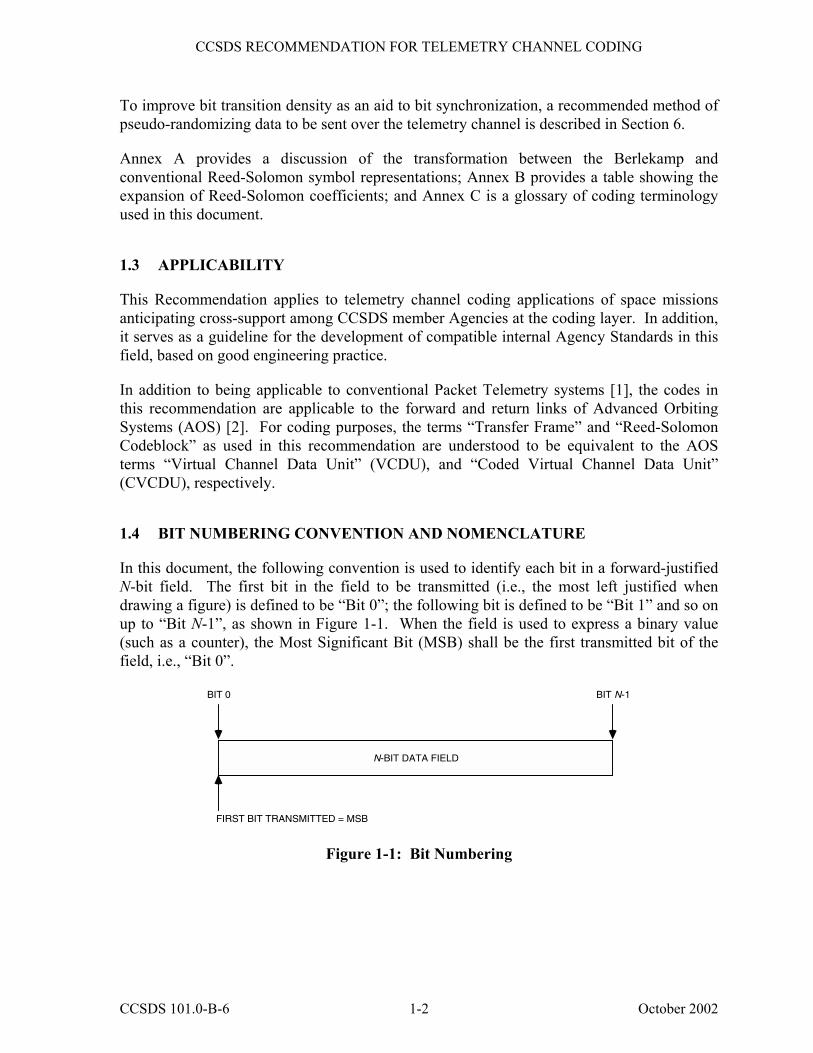
1.4 BIT NUMBERING CONVENTION AND NOMENCLATURE
In this document, the following convention is used to identify each bit in a forward-justified N-bit field. The first bit in the field to be transmitted (i.e., the most left justified when drawing a figure) is defined to be �Bit 0�; the following bit is defined to be �Bit 1� and so on up to �Bit N-1�, as shown in Figure 1-1. When the field is used to express a binary value (such as a counter), the Most Significant Bit (MSB) shall be the first transmitted bit of the field, i.e., �Bit 0�.
N-BIT DATA FIELD
BIT 0 BIT N-1
FIRST BIT TRANSMITTED = MSB
Figure 1-1: Bit Numbering
CCSDS 101.0-B-6 1-2 October 2002
CCSDS RECOMMENDATION FOR TELEMETRY CHANNEL CODING
In accordance with modern data communications practice, spacecraft data fields are often grouped into 8-bit �words� which conform to the above convention. Throughout this Recommendation, the following nomenclature is used to describe this grouping:
8-BIT WORD = “OCTET”
1.5 REFERENCES
The following documents are referenced in this Recommendation. At the time of publication, the editions indicated were valid. All documents are subject to revision, and users of this Recommendation are encouraged to investigate the possibility of applying the most recent editions of the documents indicated below. The CCSDS Secretariat maintains a register of currently valid CCSDS Recommendations.
[1] Packet Telemetry. Recommendation for Space Data System Standards, CCSDS 102.0-B-5. Blue Book. Issue 5. Washington, D.C.: CCSDS, November 2000.
[2] Advanced Orbiting Systems, Networks and Data Links: Architectural Specification. Recommendation for Space Data System Standards, CCSDS 701.0-B-3. Blue Book. Issue 3. Washington, D.C.: CCSDS, June 2001.
[3] Recommendation 2.4.9, �Minimum Modulated Symbol Transition Density on the Space-to-Earth Link� in Radio Frequency and Modulation Systems�Part 1: Earth Stations and Spacecraft. Recommendations for Space Data System Standards, CCSDS 401.0-B. Blue Book. Washington, D.C.: CCSDS, June 2001.
CCSDS 101.0-B-6 1-3 October 2002
CCSDS RECOMMENDATION FOR TELEMETRY CHANNEL CODING
2 CONVOLUTIONAL CODING
2.1 BASIC CONVOLUTIONAL CODE
2.1.1 BASIC CONVOLUTIONAL CODE DESCRIPTION
The basic convolutional code is a rate 1/2, constraint-length 7 transparent code which is well suited for channels with predominantly Gaussian noise. This code is defined in 2.1.2. When this code is punctured according to 2.2, higher code rates (lower overhead) may be achieved, although with somewhat lower error correcting performance.
The convolutional decoder is a maximum-likelihood (Viterbi) decoder.
NOTES
1 Basic convolutional code, by itself, cannot guarantee sufficient symbol transitions when multiplexing schemes are used, e.g., those implemented in QPSK. Therefore, the Pseudo-Randomizer defined in Section 6 is required unless the system designer verifies that sufficient symbol transition density is assured by other means when the Randomizer is not used.
2 If the decoder�s correction capability is exceeded, undetected burst errors may appear in the output. For this reason, when CCSDS Transfer Frames or Virtual Channel Data Units are used, references [1] and [2], respectively, require that a cyclic redundancy check (CRC) be used to validate the frame unless the Reed-Solomon code is used.
It is recommended that soft bit decisions with at least 3-bit quantization be used whenever constraints (such as location of decoder) permit.
CCSDS 101.0-B-6 2-1 October 2002
CCSDS RECOMMENDATION FOR TELEMETRY CHANNEL CODING
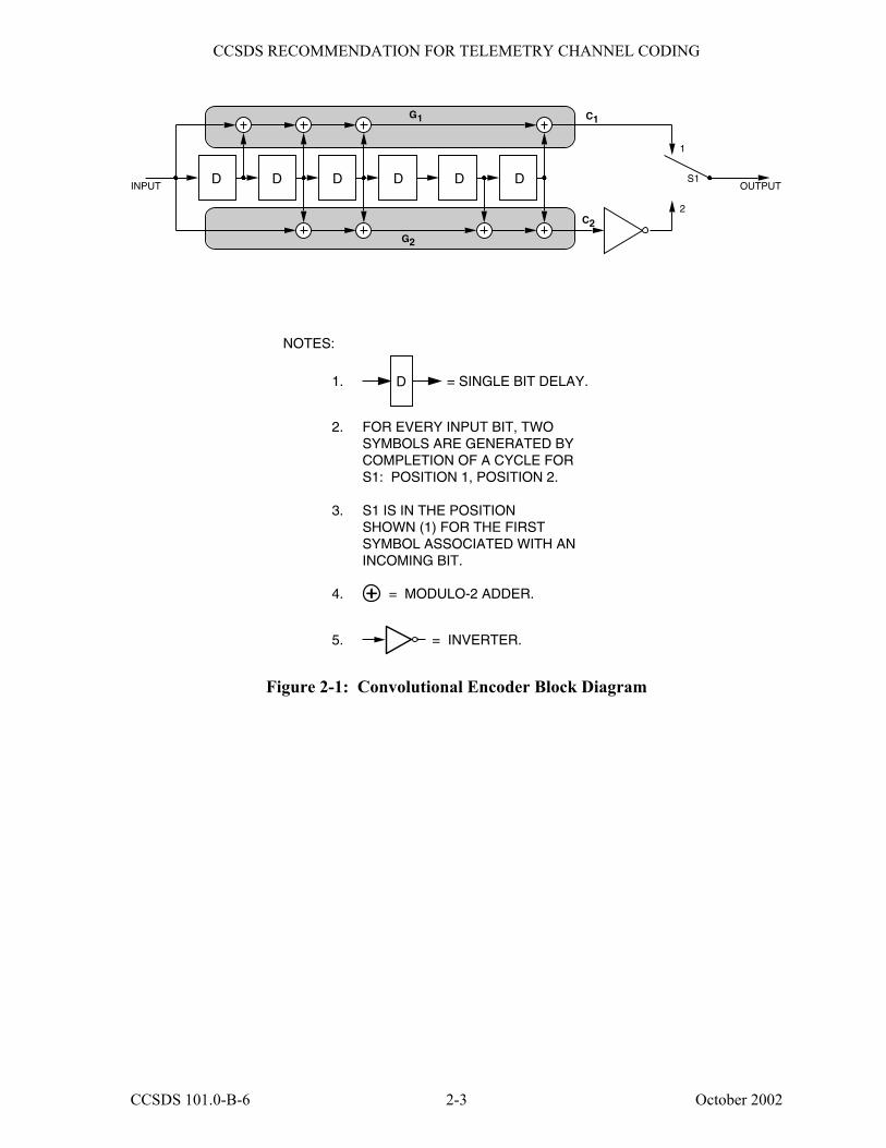
2.1.2 BASIC CONVOLUTIONAL CODE SPECIFICATION
This recommendation is a non-systematic code and a specific decoding procedure, with the following characteristics:1
(1) Nomenclature: Convolutional code with maximum-likelihood
(Viterbi) decoding. (2) Code rate: 1/2 bit per symbol. (3) Constraint length: 7 bits. (4) Connection vectors: G1 = 1111001 (171 octal); G2 = 1011011 (133 octal). (5) Symbol inversion: On output path of G2.
An encoder block diagram is shown in Figure 2-1.
The output symbol sequence is: C1(1), ____C2(1), C1(2),
____C2(2). . . .
1 When suppressed-carrier modulation systems are used, NRZ-M or NRZ-L may be used as a modulating waveform. If the
user contemplates conversion of his modulating waveform from NRZ-L to NRZ-M, such conversion should be performed on-board at the input to the convolutional encoder. Correspondingly, the conversion on the ground from NRZ-M to NRZ-L should be performed at the output of the convolutional decoder. This avoids unnecessary link performance loss.
CAUTION � When a fixed pattern (the fixed part of the convolutionally encoded Attached Sync Marker) in
the symbol stream is used to provide node synchronization for the Viterbi decoder, care must be taken to account for any modification of the pattern due to the modulating waveform conversion.
CCSDS 101.0-B-6 2-2 October 2002
CCSDS RECOMMENDATION FOR TELEMETRY CHANNEL CODING
= SINGLE BIT DELAY.
FOR EVERY INPUT BIT, TWO SYMBOLS ARE GENERATED BY COMPLETION OF A CYCLE FOR S1: POSITION 1, POSITION 2. S1 IS IN THE POSITION SHOWN (1) FOR THE FIRST SYMBOL ASSOCIATED WITH AN INCOMING BIT.
= MODULO-2 ADDER.
= INVERTER.
NOTES:
1. 2. 3.
4.
5.
D
G2
G1
OUTPUT
2
1
INPUTS1
C1
C2
DDDDDD
Figure 2-1: Convolutional Encoder Block Diagram
CCSDS 101.0-B-6 2-3 October 2002
CCSDS RECOMMENDATION FOR TELEMETRY CHANNEL CODING
2.2 PUNCTURED CONVOLUTIONAL CODES
2.2.1 GENERAL
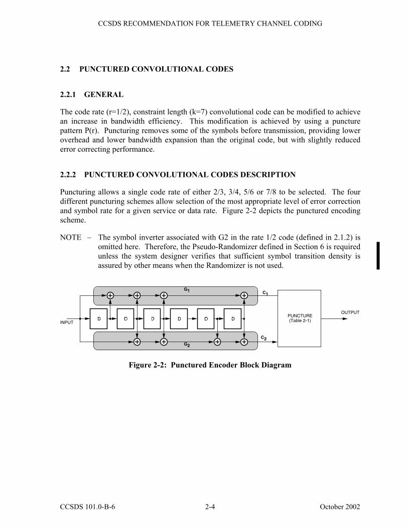
The code rate (r=1/2), constraint length (k=7) convolutional code can be modified to achieve an increase in bandwidth efficiency. This modification is achieved by using a puncture pattern P(r). Puncturing removes some of the symbols before transmission, providing lower overhead and lower bandwidth expansion than the original code, but with slightly reduced error correcting performance.
2.2.2 PUNCTURED CONVOLUTIONAL CODES DESCRIPTION
Puncturing allows a single code rate of either 2/3, 3/4, 5/6 or 7/8 to be selected. The four different puncturing schemes allow selection of the most appropriate level of error correction and symbol rate for a given service or data rate. Figure 2-2 depicts the punctured encoding scheme.
NOTE � The symbol inverter associated with G2 in the rate 1/2 code (defined in 2.1.2) is omitted here. Therefore, the Pseudo-Randomizer defined in Section 6 is required unless the system designer verifies that sufficient symbol transition density is assured by other means when the Randomizer is not used.
G2
G1
OUTPUT
INPUT
C1
C2
PUNCTURE(Table 2-1)
Figure 2-2: Punctured Encoder Block Diagram
CCSDS 101.0-B-6 2-4 October 2002
CCSDS RECOMMENDATION FOR TELEMETRY CHANNEL CODING
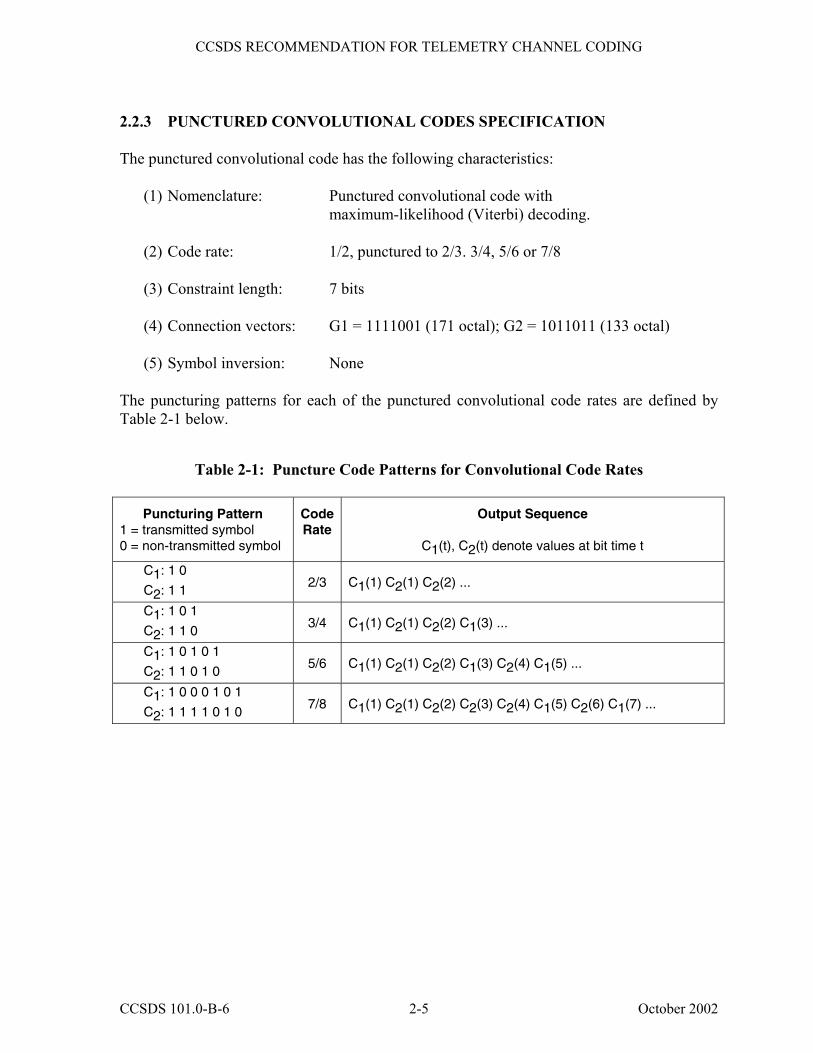
2.2.3 PUNCTURED CONVOLUTIONAL CODES SPECIFICATION The punctured convolutional code has the following characteristics:
(1) Nomenclature: Punctured convolutional code with maximum-likelihood (Viterbi) decoding.
(2) Code rate: 1/2, punctured to 2/3. 3/4, 5/6 or 7/8 (3) Constraint length: 7 bits (4) Connection vectors: G1 = 1111001 (171 octal); G2 = 1011011 (133 octal) (5) Symbol inversion: None
The puncturing patterns for each of the punctured convolutional code rates are defined by Table 2-1 below.
Table 2-1: Puncture Code Patterns for Convolutional Code Rates
Puncturing Pattern 1 = transmitted symbol 0 = non-transmitted symbol
Code Rate
Output Sequence
C1(t), C2(t) denote values at bit time t
C1: 1 0
C2: 1 1 2/3 C1(1) C2(1) C2(2) ...
C1: 1 0 1
C2: 1 1 0 3/4 C1(1) C2(1) C2(2) C1(3) ...
C1: 1 0 1 0 1
C2: 1 1 0 1 0 5/6 C1(1) C2(1) C2(2) C1(3) C2(4) C1(5) ...
C1: 1 0 0 0 1 0 1
C2: 1 1 1 1 0 1 0 7/8 C1(1) C2(1) C2(2) C2(3) C2(4) C1(5) C2(6) C1(7) ...
CCSDS 101.0-B-6 2-5 October 2002
CCSDS RECOMMENDATION FOR TELEMETRY CHANNEL CODING
3 REED-SOLOMON CODING
3.1 INTRODUCTION
The Reed-Solomon code defined in this section is a powerful burst error correcting code. In addition, the code chosen has an extremely low undetected error rate. This means that the decoder can reliably indicate whether it can make the proper corrections or not. To achieve this reliability, proper codeblock synchronization is mandatory.
One of two different error-correcting options may be chosen. For maximum performance (at the expense of accompanying overhead) the E=16 option can correct 16 R-S symbols in error per codeword. For lower overhead (with reduced performance) the E=8 option can correct 8 R-S symbols per codeword. The two options shall not be mixed in a single telemetry stream.
NOTES
1 The extremely low undetected error rate of this code means that the R-S decoder can, with a high degree of certainty, validate the decoded codeblock and consequently the contained CCSDS Transfer Frame (reference [1]) or Virtual Channel Data Unit (reference [2]). For this reason, [1] and [2] do not require a Cyclic Redundancy Check when this Reed-Solomon Code is used.
2 The Reed-Solomon coding, by itself, cannot guarantee sufficient channel symbol transitions to keep receiver symbol synchronizers in lock. Therefore, the Pseudo-Randomizer defined in Section 6 is required unless the system designer verifies that sufficient symbol transition density is assured by other means when the Randomizer is not used.
The Reed-Solomon code may be used alone, and as such it provides an excellent forward error correction capability in a burst-noise channel. However, should the Reed-Solomon code alone not provide sufficient coding gain, it may be concatenated with the convolutional code defined in Section 2. Used this way, the Reed-Solomon code is the outer code, while the convolutional code is the inner code.
3.2 SPECIFICATION The parameters of the selected Reed-Solomon (R-S) code are as follows:
(1) J = 8 bits per R-S symbol. (2) E = Reed-Solomon error correction capability, in symbols, within an R-S
codeword. E may be selected to be 16 or 8 R-S symbols. (3) General characteristics of the Reed-Solomon code:
CCSDS 101.0-B-6 3-1 October 2002
CCSDS RECOMMENDATION FOR TELEMETRY CHANNEL CODING
(a) J, E, and I (the depth of interleaving) are independent parameters. (b) n = 2J�1 = 255 symbols per R-S codeword. (c) 2E is the number of R-S symbols among n symbols of an R-S codeword
representing parity checks. (d) k = n�2E is the number of R-S symbols among n R-S symbols of an R-S
codeword representing information.
(4) Field generator polynomial:
F(x) = x8 + x7 + x2 + x + 1
over GF(2).
(5) Code generator polynomial:
g(x) = ∏j=128 � E
127 + E ( x � α11j ) = ∑
i=0
2E Gix
i
over GF(28), where F(α) = 0.
It should be recognized that α11 is a primitive element in GF(28) and that F(x) and
g(x) characterize a (255,223) Reed-Solomon code when E = 16 and a (255,239) Reed-Solomon code when E = 8.
(6) The selected code is a systematic code. This results in a systematic codeblock.
(7) Symbol Interleaving:
The allowable values of interleaving depth are I=1, 2, 3, 4, 5, and 8. I=1 is
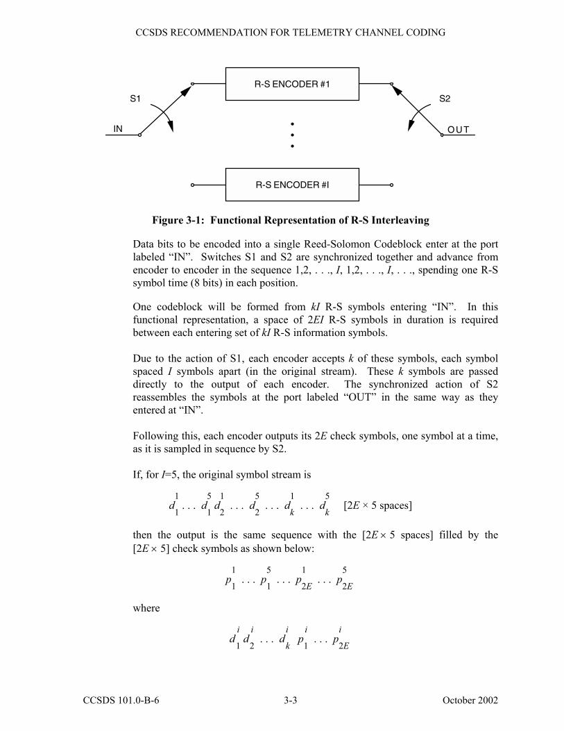
equivalent to the absence of interleaving. The interleaving depth shall normally be fixed on a physical channel for a mission. Symbol interleaving is accomplished in a manner functionally described with the aid of Figure 3-1. (It should be noted that this functional description does not necessarily correspond to the physical implementation of an encoder.)
CCSDS 101.0-B-6 3-2 October 2002
CCSDS RECOMMENDATION FOR TELEMETRY CHANNEL CODING
R-S ENCODER #I
•••
S1 S2
OUTIN
R-S ENCODER #1
Figure 3-1: Functional Representation of R-S Interleaving
Data bits to be encoded into a single Reed-Solomon Codeblock enter at the port labeled �IN�. Switches S1 and S2 are synchronized together and advance from encoder to encoder in the sequence 1,2, . . ., I, 1,2, . . ., I, . . ., spending one R-S symbol time (8 bits) in each position.
One codeblock will be formed from kI R-S symbols entering �IN�. In this
functional representation, a space of 2EI R-S symbols in duration is required between each entering set of kI R-S information symbols.
Due to the action of S1, each encoder accepts k of these symbols, each symbol
spaced I symbols apart (in the original stream). These k symbols are passed directly to the output of each encoder. The synchronized action of S2 reassembles the symbols at the port labeled �OUT� in the same way as they entered at �IN�.
Following this, each encoder outputs its 2E check symbols, one symbol at a time,
as it is sampled in sequence by S2. If, for I=5, the original symbol stream is
d1
1 . . . d
5
1 d
1
2 . . . d
5
2 . . . d
1
k . . . d
5
k [2E × 5 spaces]
then the output is the same sequence with the [2E × 5 spaces] filled by the
[2E × 5] check symbols as shown below:
p1
1 . . . p
5
1 . . . p
1
2E . . . p
5
2E
where
d i
1 d
i
2 . . . d
i
k p
i
1 . . . p
i
2E
CCSDS 101.0-B-6 3-3 October 2002
CCSDS RECOMMENDATION FOR TELEMETRY CHANNEL CODING
is the R-S codeword produced by the ith encoder. If q virtual fill symbols are used in each codeword, then replace k by (k � q) in the above discussion.
With this method of interleaving, the original kI consecutive information symbols
that entered the encoder appear unchanged at the output of the encoder with 2EI R-S check symbols appended.
(8) Maximum Codeblock Length:
The maximum codeblock length, in R-S symbols, is given by:
Lmax = nI = (2J � 1)I = 255I
(9) Shortened Codeblock Length:1
A shortened codeblock length may be used to accommodate frame lengths smaller
than the maximum. However, since the Reed-Solomon code is a block code, the decoder must always operate on a full block basis. To achieve a full codeblock, �virtual fill� must be added to make up the difference between the shortened block and the maximum codeblock length. The characteristics and limitations of virtual fill are covered in paragraph (10). Since the virtual fill is not transmitted, both encoder and decoder must be set to insert it with the proper length for the encoding and decoding processes to be carried out properly.
When an encoder (initially cleared at the start of a block) receives kI�Q symbols
representing information (where Q, representing fill, is a multiple of I, and is less than kI), 2EI check symbols are computed over kI symbols, of which the leading Q symbols are treated as all-zero symbols. A (nI�Q, kI�Q) shortened codeblock results where the leading Q symbols (all zeros) are neither entered into the encoder nor transmitted.
(10) Reed-Solomon Codeblock Partitioning and Virtual Fill:
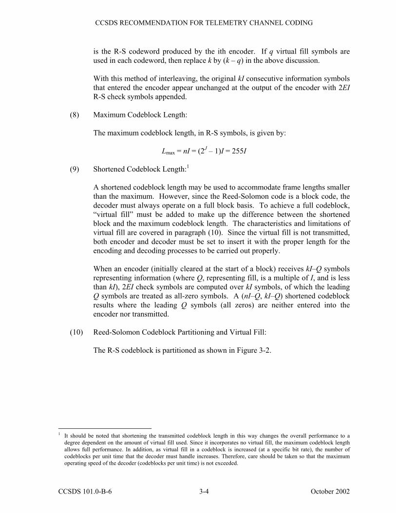
The R-S codeblock is partitioned as shown in Figure 3-2.
1 It should be noted that shortening the transmitted codeblock length in this way changes the overall performance to a
degree dependent on the amount of virtual fill used. Since it incorporates no virtual fill, the maximum codeblock length allows full performance. In addition, as virtual fill in a codeblock is increased (at a specific bit rate), the number of codeblocks per unit time that the decoder must handle increases. Therefore, care should be taken so that the maximum operating speed of the decoder (codeblocks per unit time) is not exceeded.
CCSDS 101.0-B-6 3-4 October 2002
CCSDS RECOMMENDATION FOR TELEMETRY CHANNEL CODING
SYNCR-S CHECKSYMBOLS
ATTACHEDSYNC MARKER TRANSMITTED CODEBLOCK
TRANSFER FRAME(UNCODED)
VIRTUAL FILL(OPTIONAL)
R-S CHECKSYMBOLS
TRANSFER FRAME(UNCODED)SYNC
••
••
LOGICAL CODEBLOCK
••
••
SYNC
Figure 3-2: Reed-Solomon Codeblock Partitioning
The Reed-Solomon Check Symbols consist of the trailing 2EI symbols (2EIJ bits) of the codeblock. (As an example, when E = 16 and k = 223, for I=5 this is always 1280 bits.)
The Telemetry Transfer Frame is defined by the CCSDS Recommendation for
Packet Telemetry (reference [1]). When used with R-S coding, only specified lengths may be contained within the codeblock�s data space (see subsection E3 for the allowed maximum lengths, not including the 32-bit Attached Sync Marker).
The Attached Sync Marker used with R-S coding or convolutional coding alone
is a 32-bit pattern specified in Section 5 as an aid to synchronization. It precedes the Telemetry Transfer Frame or the Transmitted Codeblock (if R-S coding is used). Frame synchronizers should, therefore, be set to expect a marker at every Telemetry Transfer Frame + 32 bits or at every Transmitted Codeblock + 32 bits (if R-S coding is used).
The Transmitted Codeblock consists of the Telemetry Transfer Frame (without
the 32-bit sync marker) and R-S check symbols. It is the received data entity physically fed into the R-S decoder. (As an example, when E = 16 and k = 223, using I=5 and no virtual fill, the length of the transmitted codeblock will be 10,200 bits; if virtual fill is used, it will be incrementally shorter, depending on the amount used.)
The Logical Codeblock is the logical data entity operated upon by the R-S
decoder. It can have a different length than the transmitted codeblock because it accounts for the amount of virtual fill that was introduced. (As an example, when E = 16 and k = 223, for I=5 the logical codeblock always appears to have exactly 10,200 bits in length.)
CCSDS 101.0-B-6 3-5 October 2002
CCSDS RECOMMENDATION FOR TELEMETRY CHANNEL CODING
Virtual fill is used to logically complete the codeblock and is not transmitted. If used, virtual fill shall:
(a) consist of all zeros;
(b) not be transmitted;
(c) not change in length during a tracking pass;
(d) be inserted only at the beginning of the codeblock (i.e., after the attached
sync marker but before the beginning of the transmitted codeblock);
(e) be inserted only in integer multiples of 8I bits.
(11) Dual basis symbol representation and ordering for transmission:
Each 8-bit Reed-Solomon symbol is an element of the finite field GF(256). Since GF(256) is a vector space of dimension 8 over the binary field GF(2), the actual 8-bit representation of a symbol is a function of the particular basis that is chosen.
One basis for GF(256) over GF(2) is the set ( 1, α1, α 2, . . ., α7). This means that any element of GF(256) has a representation of the form
u7α7 + u6α6 + . . . + u1α1 + u0α0
where each ui is either a zero or a one.
Another basis over GF(2) is the set ( 1, β 1, β 2, . . ., β 7) where β = α 117. To this
basis there exists a so-called �dual basis� (l0, l1, . . ., l7). It has the property that
1, if i = j
Tr(liβ j ) = 0, otherwise
for each j = 0, 1, . . ., 7. The function Tr(z), called the �trace�, is defined by
Tr(z) = ∑k=0
7
z2k
for each element z of GF(256). Each Reed-Solomon symbol can also be represented as
z0l0 + z1l1 + . . . + z7l7
where each zi is either a zero or a one.
CCSDS 101.0-B-6 3-6 October 2002
CCSDS RECOMMENDATION FOR TELEMETRY CHANNEL CODING
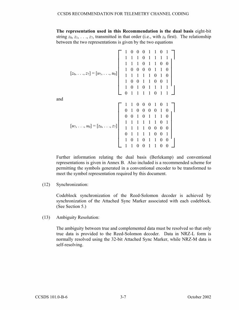
The representation used in this Recommendation is the dual basis eight-bit string z0, z1, . . ., z7, transmitted in that order (i.e., with z0 first). The relationship between the two representations is given by the two equations
[z0, . . ., z7] = [u7, . . ., u0]
1 0 0 0 1 1 0 1
1 1 1 0 1 1 1 1 1 1 1 0 1 1 0 0 1 0 0 0 0 1 1 0 1 1 1 1 1 0 1 0 1 0 0 1 1 0 0 1 1 0 1 0 1 1 1 1 0 1 1 1 1 0 1 1
and
[u7, . . ., u0] = [z0, . . ., z7]
1 1 0 0 0 1 0 1
0 1 0 0 0 0 1 0 0 0 1 0 1 1 1 0 1 1 1 1 1 1 0 1 1 1 1 1 0 0 0 0 0 1 1 1 1 0 0 1 1 0 1 0 1 1 0 0 1 1 0 0 1 1 0 0
Further information relating the dual basis (Berlekamp) and conventional
representations is given in Annex B. Also included is a recommended scheme for permitting the symbols generated in a conventional encoder to be transformed to meet the symbol representation required by this document.
(12) Synchronization:
Codeblock synchronization of the Reed-Solomon decoder is achieved by
synchronization of the Attached Sync Marker associated with each codeblock. (See Section 5.)
(13) Ambiguity Resolution:
The ambiguity between true and complemented data must be resolved so that only
true data is provided to the Reed-Solomon decoder. Data in NRZ-L form is normally resolved using the 32-bit Attached Sync Marker, while NRZ-M data is self-resolving.
CCSDS 101.0-B-6 3-7 October 2002
CCSDS RECOMMENDATION FOR TELEMETRY CHANNEL CODING
4 TURBO CODING1
4.1 INTRODUCTION
Turbo codes are binary block codes with large code blocks (hundreds or thousands of bits). They are systematic and inherently non-transparent.2 Phase ambiguities are resolved using frame markers, which are required for Codeblock synchronization.
Turbo codes may be used to obtain even greater coding gain than those provided by concatenated coding systems.
NOTES
1 Turbo coding, by itself, cannot guarantee sufficient bit transitions to keep receiver symbol synchronizers in lock. Therefore, the Pseudo-Randomizer defined in Section 6 is required unless the system designer verifies that sufficient symbol transition density is assured by other means when the Randomizer is not used.
2 While providing outstanding coding gain, turbo codes may still leave some residual errors in the decoded output. For this reason, when CCSDS Transfer Frames or Virtual Channel Data Units are used, references [1] and [2], respectively, require that a cyclic redundancy check (CRC) be used to validate the frame.
1 Implementers should be aware that a wide class of turbo codes is covered by a patent by France Télécom and
Télédiffusion de France under US Patent 5,446,747 and its counterparts in other countries. Potential user agencies should direct their requests for licenses to:
Mr. Christian HAMON CCETT GIE/CVP 4 rue du Clos Courtel BP59 35512 CESSON SEVIGNE Cedex France Tel: +33 2 99 12 48 05 Fax: +33 2 99 12 40 98 E-mail: [email protected]
2 Differential encoding (i.e., NRZ-M signaling) after the turbo encoder is not recommended since soft decoding would require the use of differential detection with considerable loss of performance. Differential encoding before the turbo encoder cannot be used because the turbo codes recommended in this document are non-transparent. This implies that phase ambiguities have to be detected and resolved by the frame synchronizer.
CCSDS 101.0-B-6 4-1 October 2002
CCSDS RECOMMENDATION FOR TELEMETRY CHANNEL CODING
4.2 SPECIFICATION
A turbo encoder is a combination of two simple encoders. The input is a frame of k information bits. The two component encoders generate parity symbols from two simple recursive convolutional codes, each with a small number of states. The information bits are also sent uncoded. A key feature of turbo codes is an interleaver, which permutes bit-wise the original k information bits before input to the second encoder.
The recommended turbo code is a systematic code with the following specifications:
(1) Code type: Systematic parallel concatenated turbo code. (2) Number of component codes: 2 (plus an uncoded component to make the
code systematic). (3) Type of component codes: Recursive convolutional codes. (4) Number of states of each
convolutional component code: 16. (5) Nominal1 Code Rates: r = 1/2, 1/3, 1/4, or 1/6 (selectable).
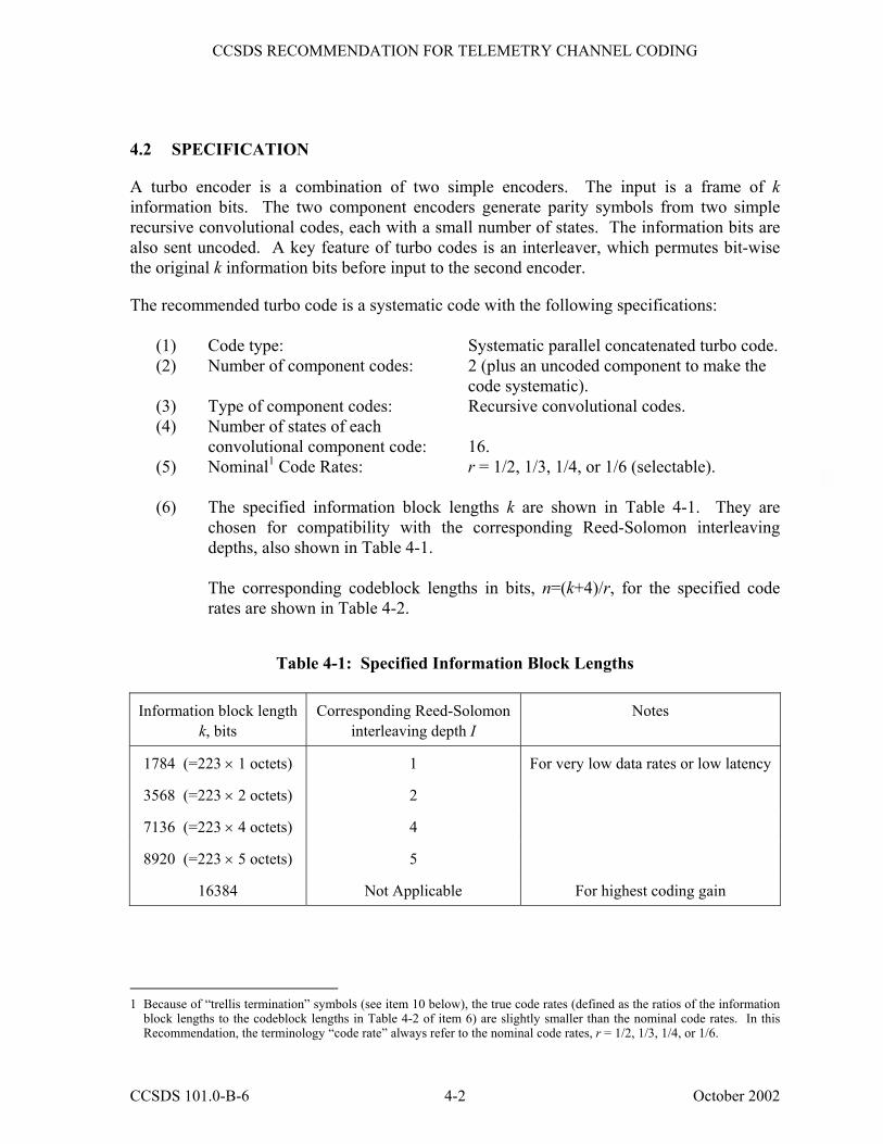
(6) The specified information block lengths k are shown in Table 4-1. They are
chosen for compatibility with the corresponding Reed-Solomon interleaving depths, also shown in Table 4-1.
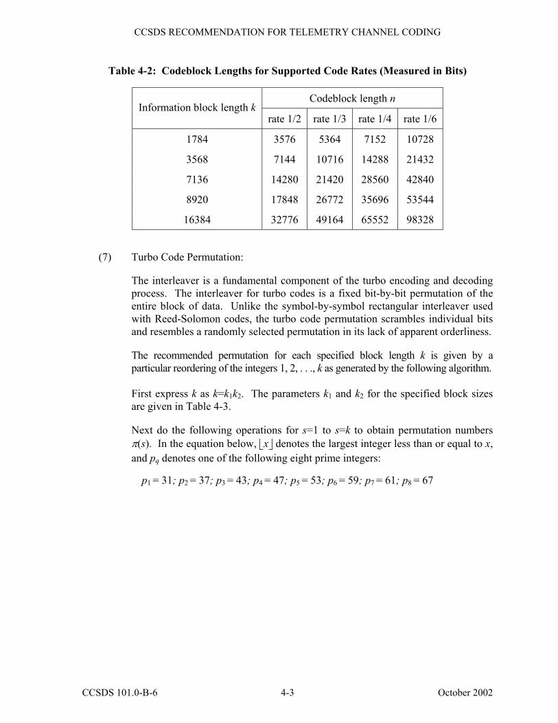
The corresponding codeblock lengths in bits, n=(k+4)/r, for the specified code
rates are shown in Table 4-2.
Table 4-1: Specified Information Block Lengths
Information block length k, bits
Corresponding Reed-Solomon interleaving depth I
Notes
1784 (=223 × 1 octets) 1 For very low data rates or low latency
3568 (=223 × 2 octets) 2
7136 (=223 × 4 octets) 4
8920 (=223 × 5 octets) 5
16384 Not Applicable For highest coding gain
1 Because of �trellis termination� symbols (see item 10 below), the true code rates (defined as the ratios of the information
block lengths to the codeblock lengths in Table 4-2 of item 6) are slightly smaller than the nominal code rates. In this Recommendation, the terminology �code rate� always refer to the nominal code rates, r = 1/2, 1/3, 1/4, or 1/6.
CCSDS 101.0-B-6 4-2 October 2002
CCSDS RECOMMENDATION FOR TELEMETRY CHANNEL CODING
Table 4-2: Codeblock Lengths for Supported Code Rates (Measured in Bits)
Codeblock length n Information block length k
rate 1/2 rate 1/3 rate 1/4 rate 1/6
1784 3576 5364 7152 10728
3568 7144 10716 14288 21432
7136 14280 21420 28560 42840
8920 17848 26772 35696 53544
16384 32776 49164 65552 98328
(7) Turbo Code Permutation:
The interleaver is a fundamental component of the turbo encoding and decoding process. The interleaver for turbo codes is a fixed bit-by-bit permutation of the entire block of data. Unlike the symbol-by-symbol rectangular interleaver used with Reed-Solomon codes, the turbo code permutation scrambles individual bits and resembles a randomly selected permutation in its lack of apparent orderliness.
The recommended permutation for each specified block length k is given by a
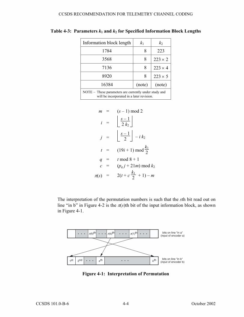
particular reordering of the integers 1, 2, . . ., k as generated by the following algorithm. First express k as k=k1k2. The parameters k1 and k2 for the specified block sizes
are given in Table 4-3.
Next do the following operations for s=1 to s=k to obtain permutation numbers π(s). In the equation below, x denotes the largest integer less than or equal to x, and pq denotes one of the following eight prime integers:
p1 = 31; p2 = 37; p3 = 43; p4 = 47; p5 = 53; p6 = 59; p7 = 61; p8 = 67
CCSDS 101.0-B-6 4-3 October 2002
CCSDS RECOMMENDATION FOR TELEMETRY CHANNEL CODING
Table 4-3: Parameters k1 and k2 for Specified Information Block Lengths
Information block length k1 k2
1784 8 223
3568 8 223 × 2
7136 8 223 × 4
8920 8 223 × 5
16384 (note) (note) NOTE � These parameters are currently under study and
will be incorporated in a later revision.
m = (s � 1) mod 2
i = s � 12 k2
j = s � 1 2 � i k2
t = (19i + 1) mod k12
q = t mod 8 + 1 c = (pq j + 21m) mod k2
π(s) = 2(t + c k1 2 + 1) � m
The interpretation of the permutation numbers is such that the sth bit read out on line �in b� in Figure 4-2 is the π(s)th bit of the input information block, as shown in Figure 4-1.
bits on line "in a"
(input of encoder a)
bits on line "in b"(input of encoder b)
π(s)th π(1)th. . . . . .
. . . . . .1st 2nd k ths th
. . .π(k)th. . .
Figure 4-1: Interpretation of Permutation
CCSDS 101.0-B-6 4-4 October 2002
CCSDS RECOMMENDATION FOR TELEMETRY CHANNEL CODING
out 0a
out 1a
out 2a
out 3a
ENCODER a
RA
TE
1/3
•
•
• •
•
RA
TE
1/4
RA
TE
1/6
•
RA
TE
1/2
= Take every other symbol
• = Take every symbol
= Exclusive OR
+ +INFORMATION
BLOCKBUFFER
in a
in b
InputInformation Block
G1
G2
G3
G0
+ + +
+ + + +
+ +
••
••
• ••
ENCODER b
+
G1
G2
G3
G0
••
• • •
Not used
out 3b
out 1b •
•
••
+ + +
+ + + +
+ +• • •
•
+
o••
+o••
••
D D D D• • • •
D D D D• • • •
D = Single bit delay
Figure 4-2: Turbo Encoder Block Diagram
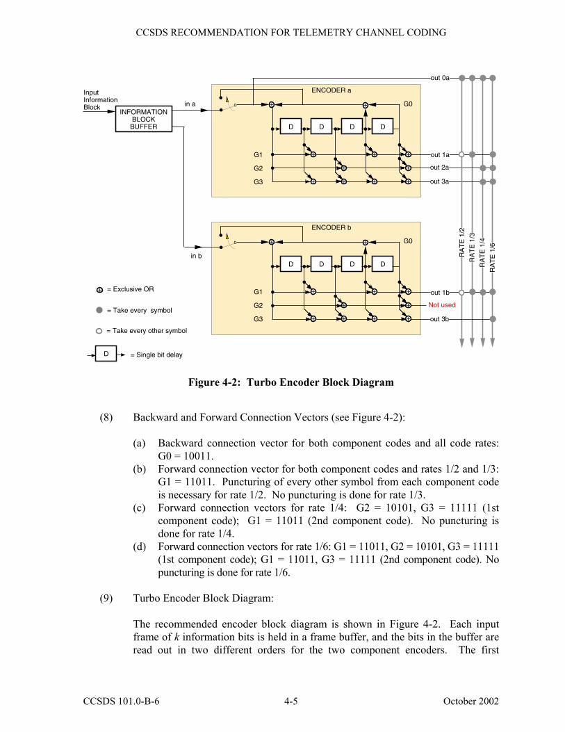
(8) Backward and Forward Connection Vectors (see Figure 4-2):
(a) Backward connection vector for both component codes and all code rates: G0 = 10011.
(b) Forward connection vector for both component codes and rates 1/2 and 1/3: G1 = 11011. Puncturing of every other symbol from each component code is necessary for rate 1/2. No puncturing is done for rate 1/3.
(c) Forward connection vectors for rate 1/4: G2 = 10101, G3 = 11111 (1st component code); G1 = 11011 (2nd component code). No puncturing is done for rate 1/4.
(d) Forward connection vectors for rate 1/6: G1 = 11011, G2 = 10101, G3 = 11111 (1st component code); G1 = 11011, G3 = 11111 (2nd component code). No puncturing is done for rate 1/6.
(9) Turbo Encoder Block Diagram: The recommended encoder block diagram is shown in Figure 4-2. Each input
frame of k information bits is held in a frame buffer, and the bits in the buffer are read out in two different orders for the two component encoders. The first
CCSDS 101.0-B-6 4-5 October 2002
CCSDS RECOMMENDATION FOR TELEMETRY CHANNEL CODING
component encoder (a) operates on the bits in unpermuted order (�in a�), while the second component encoder (b) receives the same bits permuted by the interleaver (�in b�). The read-out addressing for �in a� is a simple counter, while the addressing for �in b� is specified by the turbo code permutation described in item 7 above.
The component encoders are recursive convolutional encoders realized by
feedback shift registers as shown in Figure 4-2. The circuits shown in this figure implement the backward connection vector, G0, and the forward connection vectors, G1, G2, G3, specified in item 8 above. A key difference between these convolutional component encoders and the standalone convolutional encoder recommended in Section 2-1 is their recursiveness. In the figure this is indicated by the signal (corresponding to the backward connection vector G0) fed back into the leftmost adder of each component encoder.
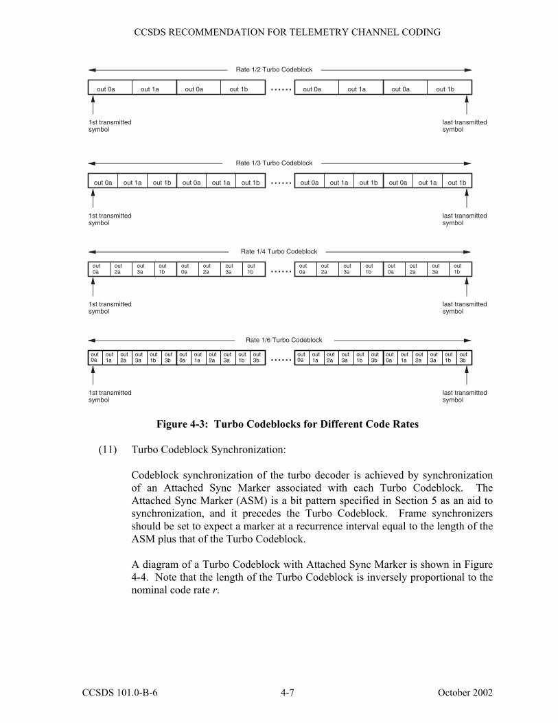
(10) Turbo Codeblock Specification:
Both component encoders in Figure 4-2 are initialized with 0s in all registers, and
both are run for a total of k+4 bit times, producing an output Codeblock of (k+4)/r encoded symbols, where r is the nominal code rate. For the first k bit times, the input switches are in the lower position (as indicated in the figure) to receive input data. For the final 4 bit times, these switches move to the upper position to receive feedback from the shift registers. This feedback cancels the same feedback sent (unswitched) to the leftmost adder and causes all four registers to become filled with zeros after the final 4 bit times. Filling the registers with zeros is called terminating the trellis. During trellis termination the encoder continues to output nonzero encoded symbols. In particular, the �systematic uncoded� output (line �out 0a� in the figure) includes an extra 4 bits from the feedback line in addition to the k information bits.
In Figure 4-2, the encoded symbols are multiplexed from top-to-bottom along the output line for the selected code rate to form the Turbo Codeblock. For the rate 1/3 code, the output sequence is (out 0a, out 1a, out 1b); for rate 1/4, the sequence is (out 0a, out 2a, out 3a, out 1b); for rate 1/6, the sequence is (out 0a, out 1a, out 2a, out 3a, out 1b, out 3b). These sequences are repeated for (k+4) bit times. For the rate 1/2 code, the output sequence is (out 0a, out 1a, out 0a, out 1b), repeated (k+4)/2 times. Note that this pattern implies that out 1b is the first to be punctured, out 1a is the second, and so forth. The Turbo Codeblocks constructed from these output sequences are depicted in Figure 4-3 for the four nominal code rates.
CCSDS 101.0-B-6 4-6 October 2002
CCSDS RECOMMENDATION FOR TELEMETRY CHANNEL CODING
Rate 1/3 Turbo Codeblock
out 0a out 1a out 1b......
1st transmittedsymbol
last transmittedsymbol
Rate 1/4 Turbo Codeblock
out 0a out 1a out 1b out 0a out 1a out 1b
......
1st transmittedsymbol
last transmittedsymbol
Rate 1/6 Turbo Codeblock
......
1st transmittedsymbol
last transmittedsymbol
Rate 1/2 Turbo Codeblock
out 0a out 1a ......
1st transmittedsymbol
last transmittedsymbol
out 0a
out 2a
out 3a
out 1b
out 0a
out 2a
out 3a
out 1b
out 0a
out 2a
out 3a
out 1b
out 0a
out 1a
out 2a
out 3a
out 1b
out 3b
out 0a
out 1a
out 2a
out 3a
out 1b
out 3b
out 0a
out 1a
out 2a
out 3a
out 1b
out 3b
out 0a out 1b out 0a out 1bout 0a out 1a
out 0a out 1a out 1b
out 0a
out 2a
out 3a
out 1b
out 0a
out 1a
out 2a
out 3a
out 1b
out 3b
Figure 4-3: Turbo Codeblocks for Different Code Rates
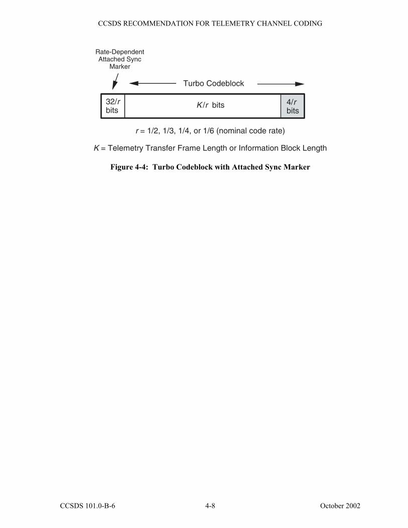
(11) Turbo Codeblock Synchronization:
Codeblock synchronization of the turbo decoder is achieved by synchronization of an Attached Sync Marker associated with each Turbo Codeblock. The Attached Sync Marker (ASM) is a bit pattern specified in Section 5 as an aid to synchronization, and it precedes the Turbo Codeblock. Frame synchronizers should be set to expect a marker at a recurrence interval equal to the length of the ASM plus that of the Turbo Codeblock.
A diagram of a Turbo Codeblock with Attached Sync Marker is shown in Figure
4-4. Note that the length of the Turbo Codeblock is inversely proportional to the nominal code rate r.
CCSDS 101.0-B-6 4-7 October 2002
CCSDS RECOMMENDATION FOR TELEMETRY CHANNEL CODING
K /r bits
Turbo Codeblock
32/rbits
Rate-Dependent Attached Sync
Marker
r = 1/2, 1/3, 1/4, or 1/6 (nominal code rate)
K = Telemetry Transfer Frame Length or Information Block Length
4/r bits
Figure 4-4: Turbo Codeblock with Attached Sync Marker
CCSDS 101.0-B-6 4-8 October 2002

CCSDS RECOMMENDATION FOR TELEMETRY CHANNEL CODING
5 FRAME SYNCHRONIZATION
5.1 INTRODUCTION
Frame or Codeblock synchronization is necessary for proper decoding of Reed-Solomon Codeblocks and Turbo Codeblocks, and subsequent processing of the Transfer Frames. Furthermore, it is necessary for synchronization of the pseudo-random generator, if used (see Section 6). It is also useful in assisting the node synchronization process of the Viterbi decoder for the convolutional code.
5.2 THE ATTACHED SYNC MARKER (ASM)
Synchronization of the Reed-Solomon or Turbo Codeblock (or Transfer Frame, if the telemetry channel is not Reed-Solomon coded or turbo coded) is achieved by using a stream of fixed-length Codeblocks (or Transfer Frames) with an Attached Sync Marker (ASM) between them. Synchronization is acquired on the receiving end by recognizing the specific bit pattern of the ASM in the telemetry channel data stream; synchronization is then customarily confirmed by making further checks.
5.2.1 ENCODER SIDE
If the telemetry channel is uncoded, Reed-Solomon coded, or turbo coded, the code symbols comprising the ASM are attached directly to the encoder output without being encoded by the Reed-Solomon or turbo code. If an inner convolutional code is used in conjunction with an outer Reed-Solomon code, the ASM is encoded by the inner code but not by the outer code.
5.2.2 DECODER SIDE
For a concatenated Reed-Solomon and convolutional coding system, the ASM may be acquired either in the channel symbol domain (i.e., before any decoding) or in the domain of bits decoded by the inner code (i.e., the code symbol domain of the Reed-Solomon code). For a turbo coding system, the ASM must be acquired in the channel symbol domain (i.e., the code symbol domain of the turbo code).
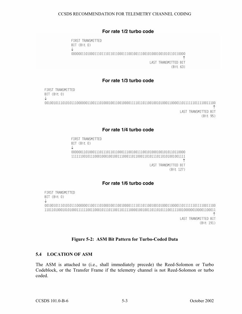
5.3 ASM BIT PATTERNS
The ASM for telemetry data that is not turbo coded shall consist of a 32-bit (4-octet) marker with a pattern shown in Figure 5-1. The ASM for data that is turbo coded with nominal code rate r = 1/2, 1/3, 1/4, or 1/6 shall consist of a 32/r-bit (4/r-octet) marker with bit patterns shown in Figure 5-2. The ASM bit patterns are represented in hexadecimal notation as:
CCSDS 101.0-B-6 5-1 October 2002
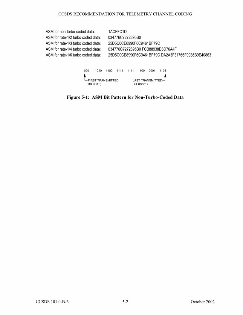
CCSDS RECOMMENDATION FOR TELEMETRY CHANNEL CODING
ASM for non-turbo-coded data: 1ACFFC1D ASM for rate-1/2 turbo coded data: 034776C7272895B0 ASM for rate-1/3 turbo coded data: 25D5C0CE8990F6C9461BF79C ASM for rate-1/4 turbo coded data: 034776C7272895B0 FCB88938D8D76A4F ASM for rate-1/6 turbo coded data: 25D5C0CE8990F6C9461BF79C DA2A3F31766F0936B9E40863
FIRST TRANSMITTED BIT (Bit 0)
LAST TRANSMITTED BIT (Bit 31)
0001 1010 1100 1111 1111 1100 0001 1101
Figure 5-1: ASM Bit Pattern for Non-Turbo-Coded Data
CCSDS 101.0-B-6 5-2 October 2002
CCSDS RECOMMENDATION FOR TELEMETRY CHANNEL CODING
For rate 1/2 turbo code
FIRST TRANSMITTED BIT (Bit 0)
↓ 0000001101000111011101101100011100100111001010001001010110110000
↑ LAST TRANSMITTED BIT (Bit 63)
For rate 1/3 turbo code
FIRST TRANSMITTED BIT (Bit 0)
↓ 001001011101010111000000110011101000100110010000111101101100100101000110000110111111011110011100
↑ LAST TRANSMITTED BIT (Bit 95)
For rate 1/4 turbo code
FIRST TRANSMITTED BIT (Bit 0)
↓ 0000001101000111011101101100011100100111001010001001010110110000 1111110010111000100010010011100011011000110101110110101001001111
↑ LAST TRANSMITTED BIT (Bit 127)
For rate 1/6 turbo code
FIRST TRANSMITTED BIT (Bit 0)
↓ 001001011101010111000000110011101000100110010000111101101100100101000110000110111111011110011100 110110100010101000111111001100010111011001101111000010010011011010111001111001000000100001100011
↑ LAST TRANSMITTED BIT (Bit 191)
Figure 5-2: ASM Bit Pattern for Turbo-Coded Data
5.4 LOCATION OF ASM
The ASM is attached to (i.e., shall immediately precede) the Reed-Solomon or Turbo Codeblock, or the Transfer Frame if the telemetry channel is not Reed-Solomon or turbo coded.
CCSDS 101.0-B-6 5-3 October 2002
CCSDS RECOMMENDATION FOR TELEMETRY CHANNEL CODING
The ASM for one Codeblock (or Transfer Frame) shall immediately follow the end of the preceding Codeblock (or Transfer Frame); i.e., there shall be no intervening bits (data or fill) preceding the ASM.
5.5 RELATIONSHIP OF ASM TO REED-SOLOMON AND TURBO CODEBLOCKS
The ASM is NOT a part of the encoded data space of the Reed-Solomon Codeblock, and it is not presented to the input of the Reed-Solomon encoder or decoder. This prevents the encoder from routinely regenerating a second, identical marker in the check symbol field under certain repeating data-dependent conditions (e.g., a test pattern of 01010101010 ... among others) which could cause synchronization difficulties at the receiving end. The relationship among the ASM, Reed-Solomon Codeblock, and Transfer Frame is illustrated in Figure 3-2.
Similarly, the ASM is not presented to the input of the turbo encoder or decoder. It is directly attached to the Turbo Codeblock, as shown in Figure 4-4.
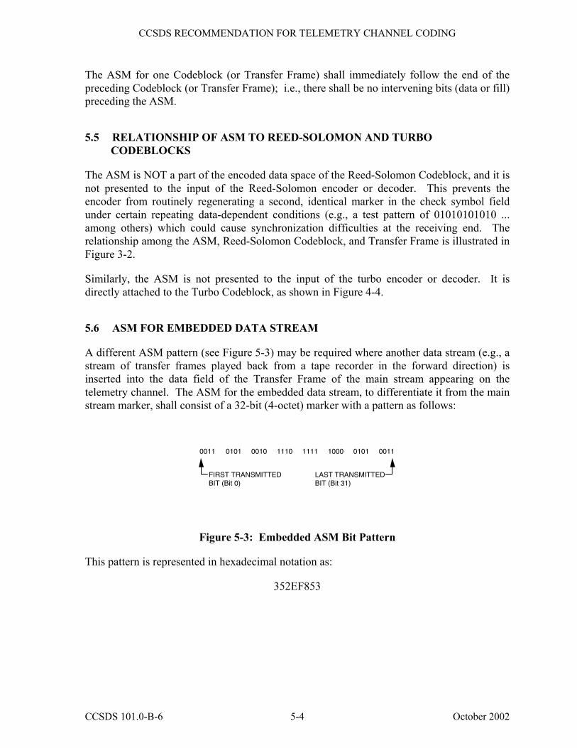
5.6 ASM FOR EMBEDDED DATA STREAM
A different ASM pattern (see Figure 5-3) may be required where another data stream (e.g., a stream of transfer frames played back from a tape recorder in the forward direction) is inserted into the data field of the Transfer Frame of the main stream appearing on the telemetry channel. The ASM for the embedded data stream, to differentiate it from the main stream marker, shall consist of a 32-bit (4-octet) marker with a pattern as follows:
FIRST TRANSMITTED BIT (Bit 0)
LAST TRANSMITTED BIT (Bit 31)
0011 0101 0010 1110 1111 1000 0101 0011
Figure 5-3: Embedded ASM Bit Pattern
This pattern is represented in hexadecimal notation as:
352EF853
CCSDS 101.0-B-6 5-4 October 2002

CCSDS RECOMMENDATION FOR TELEMETRY CHANNEL CODING
6 PSEUDO-RANDOMIZER
6.1 INTRODUCTION
In order to maintain bit (or symbol) synchronization with the received telemetry signal, every ground data capture system requires that the incoming signal have a minimum bit transition density (see reference [3]).
In order to ensure proper receiver operation, the data stream must be sufficiently random. The Pseudo-Randomizer defined in this section is the preferred method to ensure sufficient randomness for all combinations of CCSDS-recommended modulation and coding schemes. The Pseudo-Randomizer defined in this section is required unless the system designer verifies proper operation of the system if this randomizer is not used1.
The presence or absence of Pseudo-Randomization is fixed for a physical channel and is managed (i.e., its presence or absence is not signaled in the telemetry but must be known a priori) by the ground system.
6.2 PSEUDO-RANDOMIZER DESCRIPTION
The method for ensuring sufficient transitions is to exclusive-OR each bit of the Codeblock or Transfer Frame with a standard pseudo-random sequence.
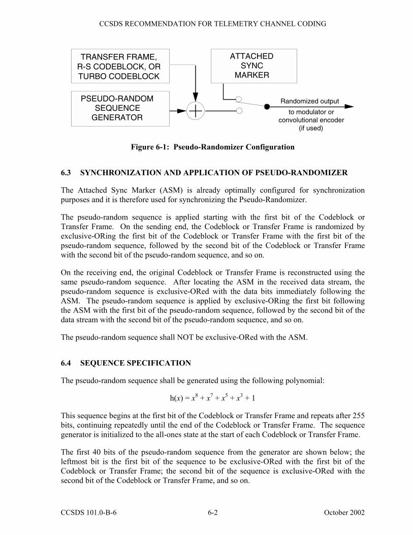
If the Pseudo-Randomizer is used, on the sending end it is applied to the Codeblock or Transfer Frame after turbo encoding or RS encoding (if either is used), but before convolutional encoding (if used). On the receiving end, it is applied to derandomize the data after convolutional decoding (if used) and codeblock synchronization but before Reed-Solomon decoding or turbo decoding (if either is used).2
The configuration at the sending end is shown in Figure 6-1.
1 Problems with telemetry links have been encountered because this Pseudo-Randomizer was not used, and sufficient
randomness was not ensured by other means and properly verified. 2 �Derandomization� consists of either: a) exclusive OR-ing the pseudo-random sequence with the received bits of a transfer
frame or a Reed-Solomon codeblock, or b) inverting (or not inverting), according to the Pseudo-Randomizer bit pattern, the demodulator output of a turbo codeblock.
CCSDS 101.0-B-6 6-1 October 2002
CCSDS RECOMMENDATION FOR TELEMETRY CHANNEL CODING
TRANSFER FRAME,R-S CODEBLOCK, ORTURBO CODEBLOCK
PSEUDO-RANDOM SEQUENCE
GENERATOR
ATTACHED SYNC
MARKER
Randomized output
to modulator or convolutional encoder
(if used)
Figure 6-1: Pseudo-Randomizer Configuration
6.3 SYNCHRONIZATION AND APPLICATION OF PSEUDO-RANDOMIZER
The Attached Sync Marker (ASM) is already optimally configured for synchronization purposes and it is therefore used for synchronizing the Pseudo-Randomizer.
The pseudo-random sequence is applied starting with the first bit of the Codeblock or Transfer Frame. On the sending end, the Codeblock or Transfer Frame is randomized by exclusive-ORing the first bit of the Codeblock or Transfer Frame with the first bit of the pseudo-random sequence, followed by the second bit of the Codeblock or Transfer Frame with the second bit of the pseudo-random sequence, and so on.
On the receiving end, the original Codeblock or Transfer Frame is reconstructed using the same pseudo-random sequence. After locating the ASM in the received data stream, the pseudo-random sequence is exclusive-ORed with the data bits immediately following the ASM. The pseudo-random sequence is applied by exclusive-ORing the first bit following the ASM with the first bit of the pseudo-random sequence, followed by the second bit of the data stream with the second bit of the pseudo-random sequence, and so on.
The pseudo-random sequence shall NOT be exclusive-ORed with the ASM.
6.4 SEQUENCE SPECIFICATION
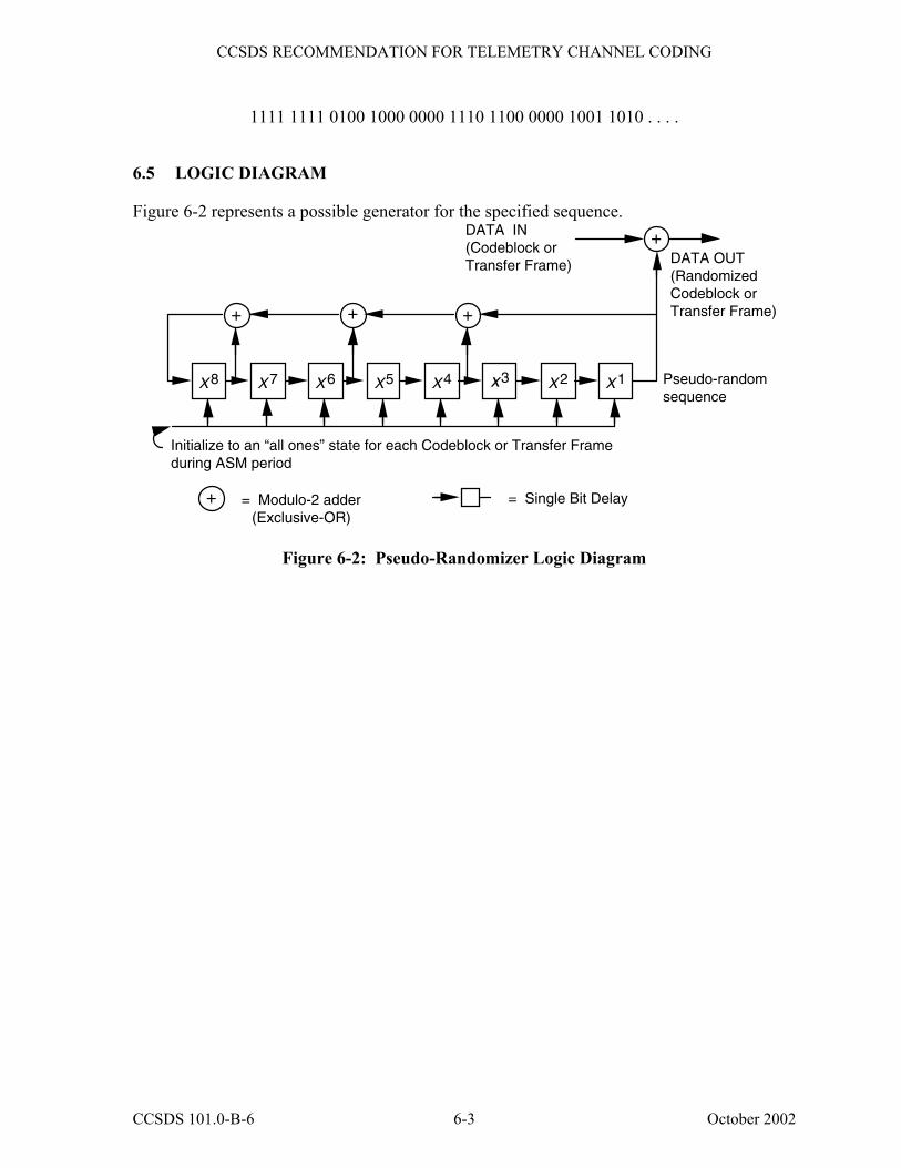
The pseudo-random sequence shall be generated using the following polynomial:
h(x) = x8 + x7 + x5 + x3 + 1
This sequence begins at the first bit of the Codeblock or Transfer Frame and repeats after 255 bits, continuing repeatedly until the end of the Codeblock or Transfer Frame. The sequence generator is initialized to the all-ones state at the start of each Codeblock or Transfer Frame.
The first 40 bits of the pseudo-random sequence from the generator are shown below; the leftmost bit is the first bit of the sequence to be exclusive-ORed with the first bit of the Codeblock or Transfer Frame; the second bit of the sequence is exclusive-ORed with the second bit of the Codeblock or Transfer Frame, and so on.
CCSDS 101.0-B-6 6-2 October 2002
CCSDS RECOMMENDATION FOR TELEMETRY CHANNEL CODING
1111 1111 0100 1000 0000 1110 1100 0000 1001 1010 . . . .
6.5 LOGIC DIAGRAM
Figure 6-2 represents a possible generator for the specified sequence.
X 8
+
+
Initialize to an “all ones” state for each Codeblock or Transfer Frame during ASM period
= Modulo-2 adder (Exclusive-OR)
+
DATA OUT (Randomized Codeblock or Transfer Frame)
DATA IN (Codeblock or Transfer Frame)
Pseudo-random sequence
= Single Bit Delay
X 7 X 6 X5 X 4 x3 X 2 X 1
++
Figure 6-2: Pseudo-Randomizer Logic Diagram
CCSDS 101.0-B-6 6-3 October 2002
CCSDS RECOMMENDATION FOR TELEMETRY CHANNEL CODING
ANNEX A
TRANSFORMATION BETWEEN BERLEKAMP AND CONVENTIONAL REPRESENTATIONS
(This annex is not part of the Recommendation)
A 1 PURPOSE
This Annex provides information to assist users of the Reed-Solomon code in this Recommendation to transform between the Berlekamp (dual basis) and Conventional representations. In addition, it shows where transformations are made to allow a conventional encoder to produce the dual basis representation on which the Recommendation is based.
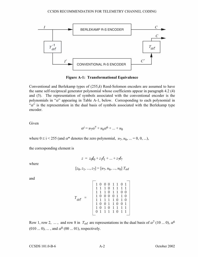
A 2 TRANSFORMATION Referring to Figure A-1, it can be seen that information symbols I entering and check symbols C emanating from the Berlekamp R-S encoder are interpreted as
[z0, z1, ... , z7] where the components zi are coefficients of li, respectively:
z0l0 + z1l1 + ... + z7l7 Information symbols I' entering and check symbols C' emanating from the conventional R-S encoder are interpreted as
[u7, u6, ... , u0] where the components uj are coefficients of α j, respectively:
u7α7 + u6α6 + ... + u0 A pre- and post-transformation is required when employing a conventional R-S encoder.
CCSDS 101.0-B-6 A-1 October 2002
CCSDS RECOMMENDATION FOR TELEMETRY CHANNEL CODING
Tα-1
I
I'
BERLEKAMP R-S ENCODER
CONVENTIONAL R-S ENCODER
C
C
C'
Tα
Figure A-1: Transformational Equivalence Conventional and Berlekamp types of (255,k) Reed-Solomon encoders are assumed to have the same self-reciprocal generator polynomial whose coefficients appear in paragraph 4.2 (4) and (5). The representation of symbols associated with the conventional encoder is the polynomials in �α� appearing in Table A-1, below. Corresponding to each polynomial in �α� is the representation in the dual basis of symbols associated with the Berlekamp type encoder. Given
αi = u7α7 + u6α6 + ... + u0
where 0 ≤ i < 255 (and α* denotes the zero polynomial, u7, u6, ... = 0, 0, ...), the corresponding element is
z = z0l0 + z1l1 + ... + z7l7 where
[z0, z1, ..., z7] = [u7, u6, ..., u0] Tα l and
11111110
01101001
01101011
00001101
11101111
11110010
01011011
11000111
T =α
Row 1, row 2, ... , and row 8 in Tα l are representations in the dual basis of α7 (10 ... 0), α6 (010 ... 0), ... , and α0 (00 ... 01), respectively.
CCSDS 101.0-B-6 A-2 October 2002
CCSDS RECOMMENDATION FOR TELEMETRY CHANNEL CODING
The inverse of Tα l is
10011011
11011101
00111110
00011100
00110111
10110011
01100000
10010100
T =α-1
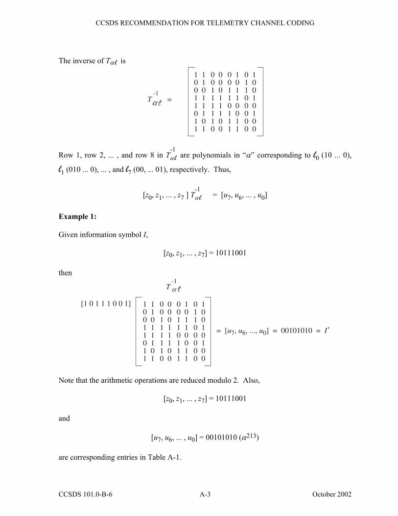
Row 1, row 2, ... , and row 8 in T-1α l are polynomials in �α� corresponding to l0 (10 ... 0),
l1 (010 ... 0), ... , and l7 (00, ... 01), respectively. Thus,
[z0, z1, ... , z7 ] T-1α l = [u7, u6, ... , u0]
Example 1: Given information symbol I,
[z0, z1, ... , z7] = 10111001 then
10011011
11011101
00111110
00011100
00110111
10110011
01100000
10010100
T-1
[1 0 1 1 1 0 0 1]
α
= [u7, u6, ..., u0] = 00101010 = I'
Note that the arithmetic operations are reduced modulo 2. Also,
[z0, z1, ... , z7] = 10111001 and
[u7, u6, ... , u0] = 00101010 (α213) are corresponding entries in Table A-1.
CCSDS 101.0-B-6 A-3 October 2002
CCSDS RECOMMENDATION FOR TELEMETRY CHANNEL CODING
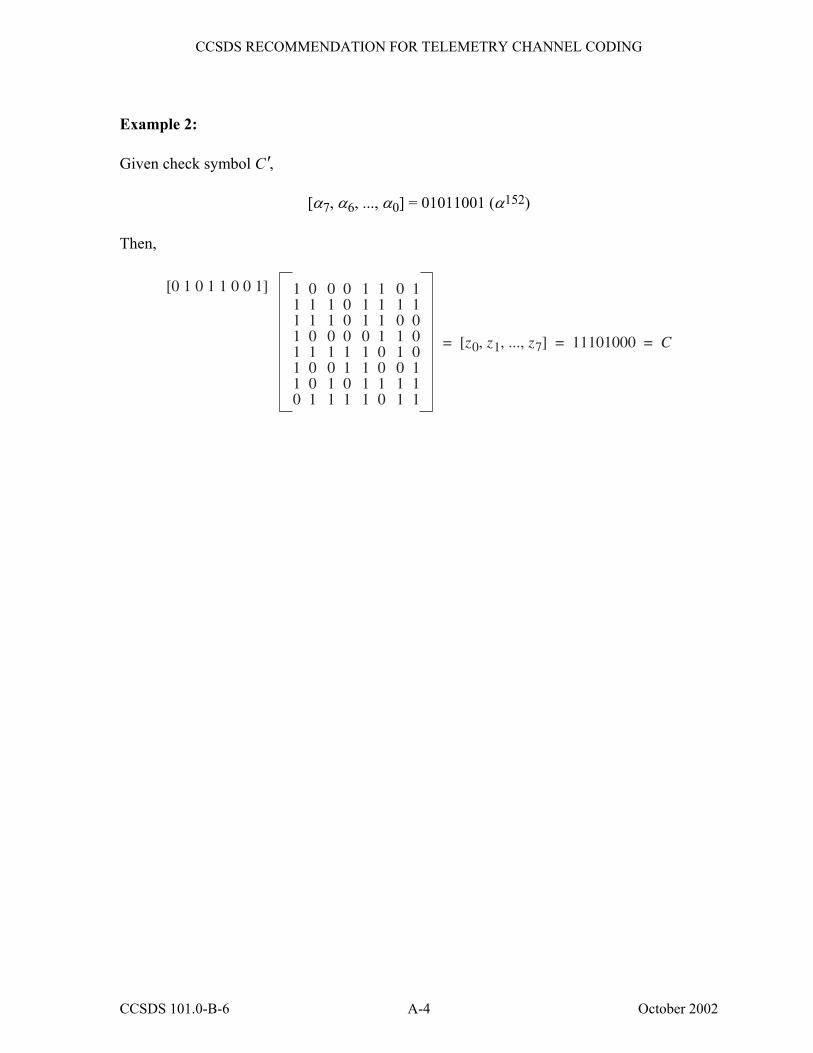
Example 2: Given check symbol C',
[α7, α6, ..., α0] = 01011001 (α152) Then,
11111110
01101001
01101011
00001101
11101111
11110010
01011011
11000111
[0 1 0 1 1 0 0 1]
= [z0, z1, ..., z7] = 11101000 = C
CCSDS 101.0-B-6 A-4 October 2002
CCSDS RECOMMENDATION FOR TELEMETRY CHANNEL CODING
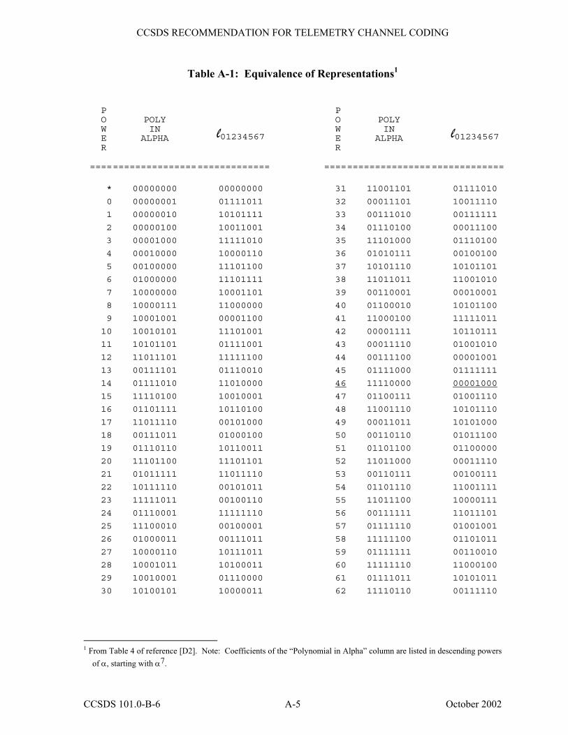
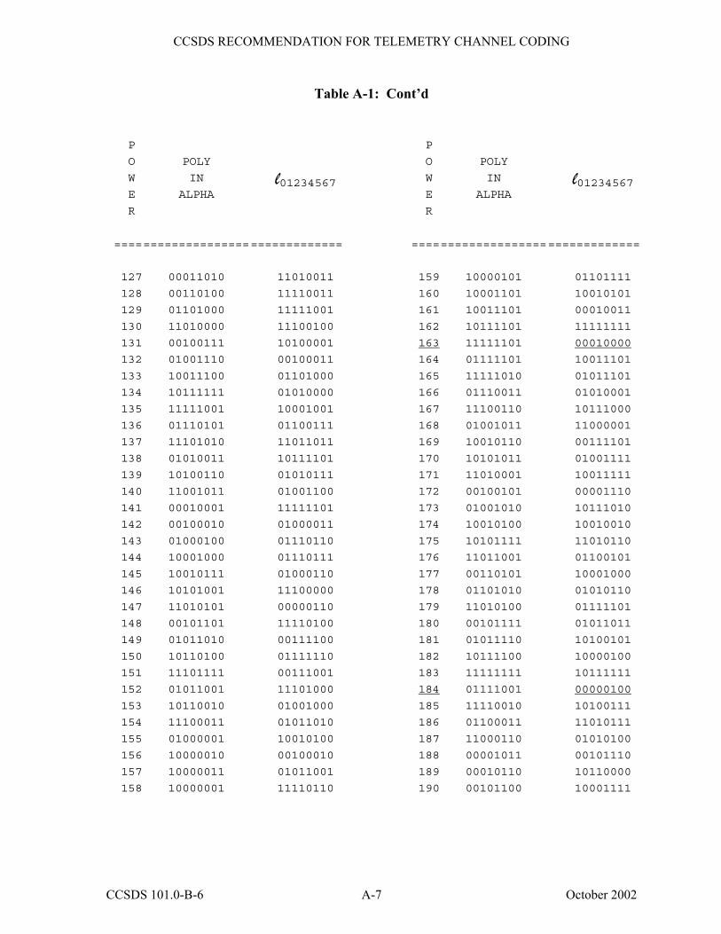
Table A-1: Equivalence of Representations1
P O W E R
POLY IN
ALPHA
l01234567
P O W E R
POLY IN
ALPHA
l01234567
==== =============== ============= =================== =============
* 00000000 00000000 31 11001101 01111010
0 00000001 01111011 32 00011101 10011110
1 00000010 10101111 33 00111010 00111111
2 00000100 10011001 34 01110100 00011100
3 00001000 11111010 35 11101000 01110100
4 00010000 10000110 36 01010111 00100100
5 00100000 11101100 37 10101110 10101101
6 01000000 11101111 38 11011011 11001010
7 10000000 10001101 39 00110001 00010001
8 10000111 11000000 40 01100010 10101100
9 10001001 00001100 41 11000100 11111011
10 10010101 11101001 42 00001111 10110111
11 10101101 01111001 43 00011110 01001010
12 11011101 11111100 44 00111100 00001001
13 00111101 01110010 45 01111000 01111111
14 01111010 11010000 46 11110000 00001000
15 11110100 10010001 47 01100111 01001110
16 01101111 10110100 48 11001110 10101110
17 11011110 00101000 49 00011011 10101000
18 00111011 01000100 50 00110110 01011100
19 01110110 10110011 51 01101100 01100000
20 11101100 11101101 52 11011000 00011110
21 01011111 11011110 53 00110111 00100111
22 10111110 00101011 54 01101110 11001111
23 11111011 00100110 55 11011100 10000111
24 01110001 11111110 56 00111111 11011101
25 11100010 00100001 57 01111110 01001001
26 01000011 00111011 58 11111100 01101011
27 10000110 10111011 59 01111111 00110010
28 10001011 10100011 60 11111110 11000100
29 10010001 01110000 61 01111011 10101011
30 10100101 10000011 62 11110110 00111110
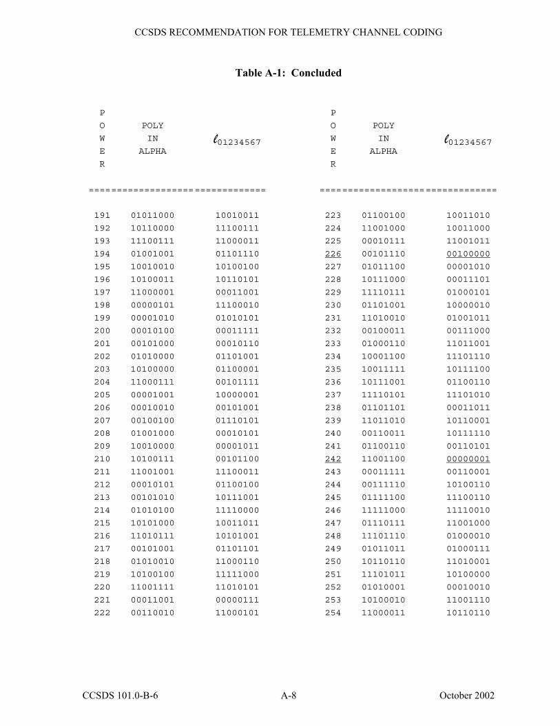
1 From Table 4 of reference [D2]. Note: Coefficients of the �Polynomial in Alpha� column are listed in descending powers
of α, starting with α7.
CCSDS 101.0-B-6 A-5 October 2002
CCSDS RECOMMENDATION FOR TELEMETRY CHANNEL CODING
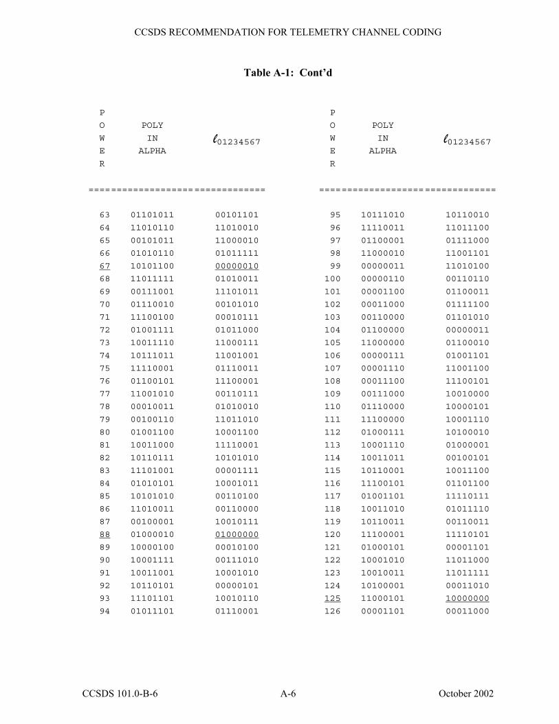
Table A-1: Cont�d
P
O
W
E
R
POLY
IN
ALPHA
l01234567
P
O
W
E
R
POLY
IN
ALPHA
l01234567
==== =============== ============= =================== =============
63 01101011 00101101 95 10111010 10110010
64 11010110 11010010 96 11110011 11011100
65 00101011 11000010 97 01100001 01111000
66 01010110 01011111 98 11000010 11001101
67 10101100 00000010 99 00000011 11010100
68 11011111 01010011 100 00000110 00110110
69 00111001 11101011 101 00001100 01100011
70 01110010 00101010 102 00011000 01111100
71 11100100 00010111 103 00110000 01101010
72 01001111 01011000 104 01100000 00000011
73 10011110 11000111 105 11000000 01100010
74 10111011 11001001 106 00000111 01001101
75 11110001 01110011 107 00001110 11001100
76 01100101 11100001 108 00011100 11100101
77 11001010 00110111 109 00111000 10010000
78 00010011 01010010 110 01110000 10000101
79 00100110 11011010 111 11100000 10001110
80 01001100 10001100 112 01000111 10100010
81 10011000 11110001 113 10001110 01000001
82 10110111 10101010 114 10011011 00100101
83 11101001 00001111 115 10110001 10011100
84 01010101 10001011 116 11100101 01101100
85 10101010 00110100 117 01001101 11110111
86 11010011 00110000 118 10011010 01011110
87 00100001 10010111 119 10110011 00110011
88 01000010 01000000 120 11100001 11110101
89 10000100 00010100 121 01000101 00001101
90 10001111 00111010 122 10001010 11011000
91 10011001 10001010 123 10010011 11011111
92 10110101 00000101 124 10100001 00011010
93 11101101 10010110 125 11000101 10000000
94 01011101 01110001 126 00001101 00011000
CCSDS 101.0-B-6 A-6 October 2002
CCSDS RECOMMENDATION FOR TELEMETRY CHANNEL CODING
Table A-1: Cont�d
P
O
W
E
R
POLY
IN
ALPHA
l01234567
P
O
W
E
R
POLY
IN
ALPHA
l01234567
==== =============== ============= =================== =============
127 00011010 11010011 159 10000101 01101111
128 00110100 11110011 160 10001101 10010101
129 01101000 11111001 161 10011101 00010011
130 11010000 11100100 162 10111101 11111111
131 00100111 10100001 163 11111101 00010000
132 01001110 00100011 164 01111101 10011101
133 10011100 01101000 165 11111010 01011101
134 10111111 01010000 166 01110011 01010001
135 11111001 10001001 167 11100110 10111000
136 01110101 01100111 168 01001011 11000001
137 11101010 11011011 169 10010110 00111101
138 01010011 10111101 170 10101011 01001111
139 10100110 01010111 171 11010001 10011111
140 11001011 01001100 172 00100101 00001110
141 00010001 11111101 173 01001010 10111010
142 00100010 01000011 174 10010100 10010010
143 01000100 01110110 175 10101111 11010110
144 10001000 01110111 176 11011001 01100101
145 10010111 01000110 177 00110101 10001000
146 10101001 11100000 178 01101010 01010110
147 11010101 00000110 179 11010100 01111101
148 00101101 11110100 180 00101111 01011011
149 01011010 00111100 181 01011110 10100101
150 10110100 01111110 182 10111100 10000100
151 11101111 00111001 183 11111111 10111111
152 01011001 11101000 184 01111001 00000100
153 10110010 01001000 185 11110010 10100111
154 11100011 01011010 186 01100011 11010111
155 01000001 10010100 187 11000110 01010100
156 10000010 00100010 188 00001011 00101110
157 10000011 01011001 189 00010110 10110000
158 10000001 11110110 190 00101100 10001111
CCSDS 101.0-B-6 A-7 October 2002
CCSDS RECOMMENDATION FOR TELEMETRY CHANNEL CODING
Table A-1: Concluded
P
O
W
E
R
POLY
IN
ALPHA
l01234567
P
O
W
E
R
POLY
IN
ALPHA
l01234567
==== =============== ============= =================== =============
191 01011000 10010011 223 01100100 10011010
192 10110000 11100111 224 11001000 10011000
193 11100111 11000011 225 00010111 11001011
194 01001001 01101110 226 00101110 00100000
195 10010010 10100100 227 01011100 00001010
196 10100011 10110101 228 10111000 00011101
197 11000001 00011001 229 11110111 01000101
198 00000101 11100010 230 01101001 10000010
199 00001010 01010101 231 11010010 01001011
200 00010100 00011111 232 00100011 00111000
201 00101000 00010110 233 01000110 11011001
202 01010000 01101001 234 10001100 11101110
203 10100000 01100001 235 10011111 10111100
204 11000111 00101111 236 10111001 01100110
205 00001001 10000001 237 11110101 11101010
206 00010010 00101001 238 01101101 00011011
207 00100100 01110101 239 11011010 10110001
208 01001000 00010101 240 00110011 10111110
209 10010000 00001011 241 01100110 00110101
210 10100111 00101100 242 11001100 00000001
211 11001001 11100011 243 00011111 00110001
212 00010101 01100100 244 00111110 10100110
213 00101010 10111001 245 01111100 11100110
214 01010100 11110000 246 11111000 11110010
215 10101000 10011011 247 01110111 11001000
216 11010111 10101001 248 11101110 01000010
217 00101001 01101101 249 01011011 01000111
218 01010010 11000110 250 10110110 11010001
219 10100100 11111000 251 11101011 10100000
220 11001111 11010101 252 01010001 00010010
221 00011001 00000111 253 10100010 11001110
222 00110010 11000101 254 11000011 10110110
CCSDS 101.0-B-6 A-8 October 2002
CCSDS RECOMMENDATION FOR TELEMETRY CHANNEL CODING
ANNEX B
EXPANSION OF REED-SOLOMON COEFFICIENTS
(This annex is not part of the Recommendation.)
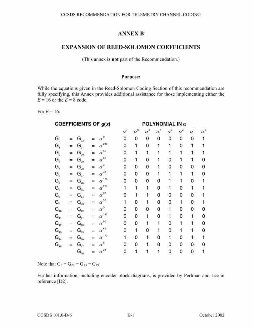
Purpose: While the equations given in the Reed-Solomon Coding Section of this recommendation are fully specifying, this Annex provides additional assistance for those implementing either the E = 16 or the E = 8 code. For E = 16:
COEFFICIENTS OF g(x) POLYNOMIAL IN α α 7 α 6 α 5 α 4 α 3 α 2 α 1 α 0 G0 = G32 = α 0 0 0 0 0 0 0 0 1 G1 = G31 = α 249 0 1 0 1 1 0 1 1 G2 = G30 = α 59 0 1 1 1 1 1 1 1 G3 = G29 = α 66 0 1 0 1 0 1 1 0 G4 = G28 = α 4 0 0 0 1 0 0 0 0 G5 = G27 = α 43 0 0 0 1 1 1 1 0 G6 = G26 = α 126 0 0 0 0 1 1 0 1 G7 = G25 = α 251 1 1 1 0 1 0 1 1 G8 = G24 = α 97 0 1 1 0 0 0 0 1 G9 = G23 = α 30 1 0 1 0 0 1 0 1 G10 = G22 = α 3 0 0 0 0 1 0 0 0 G11 = G21 = α 213 0 0 1 0 1 0 1 0 G12 = G20 = α 50 0 0 1 1 0 1 1 0 G13 = G19 = α 66 0 1 0 1 0 1 1 0 G14 = G18 = α 170 1 0 1 0 1 0 1 1 G15 = G17 = α 5 0 0 1 0 0 0 0 0 G16 = α 24 0 1 1 1 0 0 0 1
Note that G3 = G29 = G13 = G19 Further information, including encoder block diagrams, is provided by Perlman and Lee in reference [D2].
CCSDS 101.0-B-6 B-1 October 2002
CCSDS RECOMMENDATION FOR TELEMETRY CHANNEL CODING
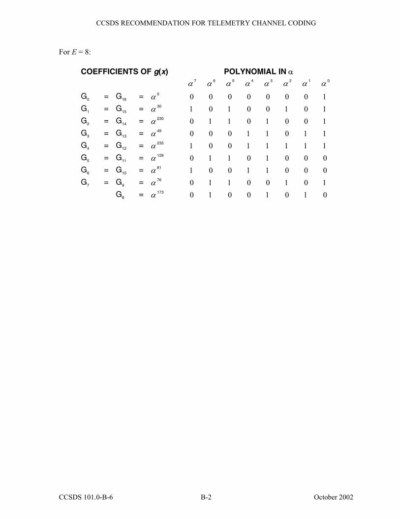
For E = 8:
COEFFICIENTS OF g(x) POLYNOMIAL IN α α 7 α 6 α 5 α 4 α 3 α 2 α 1 α 0
G0 = G16 = α 0 0 0 0 0 0 0 0 1 G1 = G15 = α 30 1 0 1 0 0 1 0 1 G2 = G14 = α 230 0 1 1 0 1 0 0 1 G3 = G13 = α 49 0 0 0 1 1 0 1 1 G4 = G12 = α 235 1 0 0 1 1 1 1 1 G5 = G11 = α 129 0 1 1 0 1 0 0 0 G6 = G10 = α 81 1 0 0 1 1 0 0 0 G7 = G9 = α 76 0 1 1 0 0 1 0 1 G8 = α 173 0 1 0 0 1 0 1 0
CCSDS 101.0-B-6 B-2 October 2002

CCSDS RECOMMENDATION FOR TELEMETRY CHANNEL CODING
ANNEX C
GLOSSARY OF ACRONYMS AND TERMS
(This annex is not part of the Recommendation.)
C 1 PURPOSE
This annex defines key acronyms and terms that are used throughout this Recommendation to describe telemetry channel coding.
C 2 TERMS BLOCK ENCODING: A one-to-one transformation of sequences of length k of elements of a source alphabet to sequences of length n of elements of a code alphabet, n>k. CHANNEL SYMBOL: The unit of output of the innermost encoder. CODEBLOCK: A codeblock of an (n,k) block code is a sequence of n channel symbols which were produced as a unit by encoding a sequence of k information symbols, and will be decoded as a unit. CODE RATE: The average ratio of the number of binary digits at the input of an encoder to the number of binary digits at its output. CODEWORD: In a block code, one of the sequences in the range of the one-to-one transformation (see BLOCK ENCODING). CONCATENATION: The use of two or more codes to process data sequentially with the output of one encoder used as the input of the next. CONNECTION VECTOR (FORWARD): In convolutional and turbo coding, a vector used to specify one of the parity checks to be computed by the shift register(s) in the encoder. For a shift register with s stages, a connection vector is an s-bit binary number. A bit equal to �one� in position i (counted from the left) indicates that the output of the ith stage of the shift register is to be used in computing that parity check. CONNECTION VECTOR (BACKWARD): In turbo coding, a vector used to specify the feedback to the shift registers in the encoder. For a shift register with s stages, a backward connection vector is an s-bit binary number. A bit equal to �one� in position i (counted from the left) indicates that the output of the ith stage of the shift register is to be used in computing the feedback value, except for the leftmost bit which is ignored.
CCSDS 101.0-B-6 C-1 October 2002
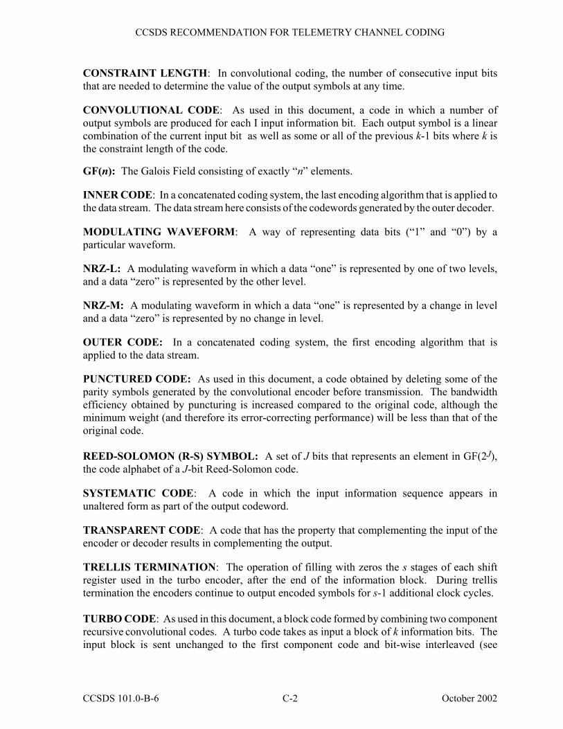
CCSDS RECOMMENDATION FOR TELEMETRY CHANNEL CODING
CONSTRAINT LENGTH: In convolutional coding, the number of consecutive input bits that are needed to determine the value of the output symbols at any time. CONVOLUTIONAL CODE: As used in this document, a code in which a number of output symbols are produced for each I input information bit. Each output symbol is a linear combination of the current input bit as well as some or all of the previous k-1 bits where k is the constraint length of the code. GF(n): The Galois Field consisting of exactly �n� elements. INNER CODE: In a concatenated coding system, the last encoding algorithm that is applied to the data stream. The data stream here consists of the codewords generated by the outer decoder. MODULATING WAVEFORM: A way of representing data bits (�1� and �0�) by a particular waveform. NRZ-L: A modulating waveform in which a data �one� is represented by one of two levels, and a data �zero� is represented by the other level. NRZ-M: A modulating waveform in which a data �one� is represented by a change in level and a data �zero� is represented by no change in level. OUTER CODE: In a concatenated coding system, the first encoding algorithm that is applied to the data stream. PUNCTURED CODE: As used in this document, a code obtained by deleting some of the parity symbols generated by the convolutional encoder before transmission. The bandwidth efficiency obtained by puncturing is increased compared to the original code, although the minimum weight (and therefore its error-correcting performance) will be less than that of the original code. REED-SOLOMON (R-S) SYMBOL: A set of J bits that represents an element in GF(2J), the code alphabet of a J-bit Reed-Solomon code. SYSTEMATIC CODE: A code in which the input information sequence appears in unaltered form as part of the output codeword. TRANSPARENT CODE: A code that has the property that complementing the input of the encoder or decoder results in complementing the output. TRELLIS TERMINATION: The operation of filling with zeros the s stages of each shift register used in the turbo encoder, after the end of the information block. During trellis termination the encoders continue to output encoded symbols for s-1 additional clock cycles. TURBO CODE: As used in this document, a block code formed by combining two component recursive convolutional codes. A turbo code takes as input a block of k information bits. The input block is sent unchanged to the first component code and bit-wise interleaved (see
CCSDS 101.0-B-6 C-2 October 2002

CCSDS RECOMMENDATION FOR TELEMETRY CHANNEL CODING
TURBO CODE PERMUTATION) to the second component code. The output is formed by the parity symbols contributed by each component code plus a replica of the information bits. TURBO CODE PERMUTATION: A fixed bit-by-bit permutation of the entire input block of information bits performed by an interleaver, used in turbo codes. VIRTUAL FILL: In a systematic block code, a codeword can be divided into an information part and a parity (check) part. Suppose that the information part is N symbols long (a symbol is defined here to be an element of the code�s alphabet) and that the parity part is M symbols long. A �shortened� code is created by taking only S (S < N) information symbols as input, appending a fixed string of length N-S and then encoding in the normal way. This fixed string is called �fill� Since the fill is a predetermined sequence of symbols, it need not be transmitted over the channel. Instead, the decoder appends the same fill sequence before decoding. In this case, the fill is called �Virtual Fill�.
CCSDS 101.0-B-6 C-3 October 2002
CCSDS RECOMMENDATION FOR TELEMETRY CHANNEL CODING
ANNEX D
INFORMATIVE REFERENCES
(This annex is not part of the Recommendation.)
[D1] Procedures Manual for the Consultative Committee for Space Data Systems. CCSDS A00.0-Y-8. Yellow Book. Issue 8. Washington, D.C.: CCSDS, July 2002.
[D2] M. Perlman and J. Lee. Reed-Solomon Encoders�Conventional vs. Berlekamp�s Architecture. JPL Publication 82-71. Pasadena, California: NASA-Jet Propulsion Laboratory, December 1982.
CCSDS 101.0-B-6 D-1 October 2002
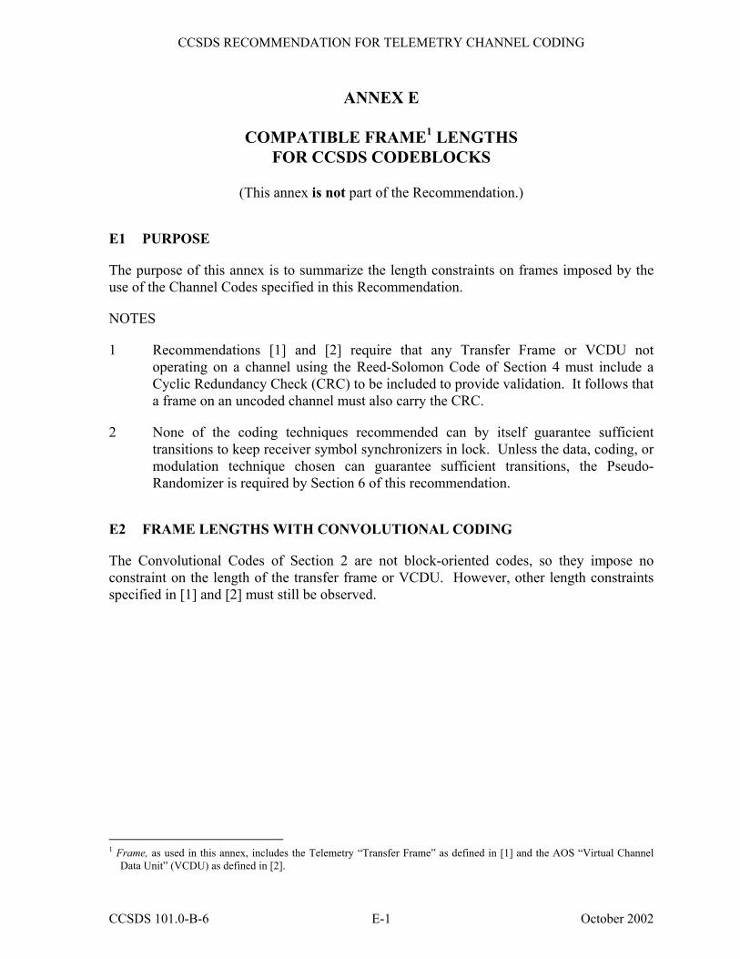
CCSDS RECOMMENDATION FOR TELEMETRY CHANNEL CODING
ANNEX E
COMPATIBLE FRAME1 LENGTHS FOR CCSDS CODEBLOCKS
(This annex is not part of the Recommendation.)
E1 PURPOSE
The purpose of this annex is to summarize the length constraints on frames imposed by the use of the Channel Codes specified in this Recommendation.
NOTES
1 Recommendations [1] and [2] require that any Transfer Frame or VCDU not operating on a channel using the Reed-Solomon Code of Section 4 must include a Cyclic Redundancy Check (CRC) to be included to provide validation. It follows that a frame on an uncoded channel must also carry the CRC.
2 None of the coding techniques recommended can by itself guarantee sufficient transitions to keep receiver symbol synchronizers in lock. Unless the data, coding, or modulation technique chosen can guarantee sufficient transitions, the Pseudo-Randomizer is required by Section 6 of this recommendation.
E2 FRAME LENGTHS WITH CONVOLUTIONAL CODING
The Convolutional Codes of Section 2 are not block-oriented codes, so they impose no constraint on the length of the transfer frame or VCDU. However, other length constraints specified in [1] and [2] must still be observed.
1 Frame, as used in this annex, includes the Telemetry �Transfer Frame� as defined in [1] and the AOS �Virtual Channel
Data Unit� (VCDU) as defined in [2].
CCSDS 101.0-B-6 E-1 October 2002
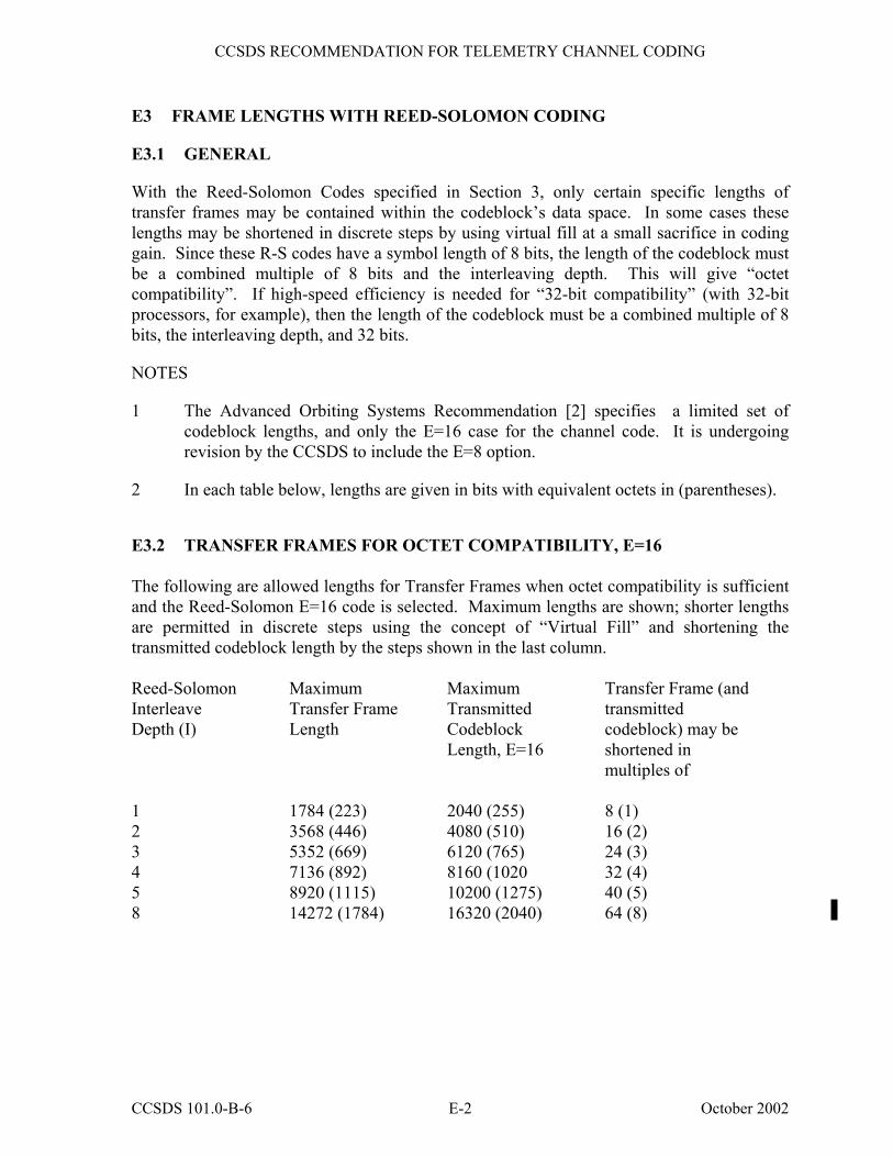
CCSDS RECOMMENDATION FOR TELEMETRY CHANNEL CODING
E3 FRAME LENGTHS WITH REED-SOLOMON CODING
E3.1 GENERAL
With the Reed-Solomon Codes specified in Section 3, only certain specific lengths of transfer frames may be contained within the codeblock�s data space. In some cases these lengths may be shortened in discrete steps by using virtual fill at a small sacrifice in coding gain. Since these R-S codes have a symbol length of 8 bits, the length of the codeblock must be a combined multiple of 8 bits and the interleaving depth. This will give �octet compatibility�. If high-speed efficiency is needed for �32-bit compatibility� (with 32-bit processors, for example), then the length of the codeblock must be a combined multiple of 8 bits, the interleaving depth, and 32 bits.
NOTES
1 The Advanced Orbiting Systems Recommendation [2] specifies a limited set of codeblock lengths, and only the E=16 case for the channel code. It is undergoing revision by the CCSDS to include the E=8 option.
2 In each table below, lengths are given in bits with equivalent octets in (parentheses).
E3.2 TRANSFER FRAMES FOR OCTET COMPATIBILITY, E=16 The following are allowed lengths for Transfer Frames when octet compatibility is sufficient and the Reed-Solomon E=16 code is selected. Maximum lengths are shown; shorter lengths are permitted in discrete steps using the concept of �Virtual Fill� and shortening the transmitted codeblock length by the steps shown in the last column. Reed-Solomon Interleave Depth (I)
Maximum Transfer Frame Length
Maximum Transmitted Codeblock Length, E=16
Transfer Frame (and transmitted codeblock) may be shortened in multiples of
1 1784 (223) 2040 (255) 8 (1) 2 3568 (446) 4080 (510) 16 (2) 3 5352 (669) 6120 (765) 24 (3) 4 7136 (892) 8160 (1020 32 (4) 5 8920 (1115) 10200 (1275) 40 (5) 8 14272 (1784) 16320 (2040) 64 (8)
CCSDS 101.0-B-6 E-2 October 2002
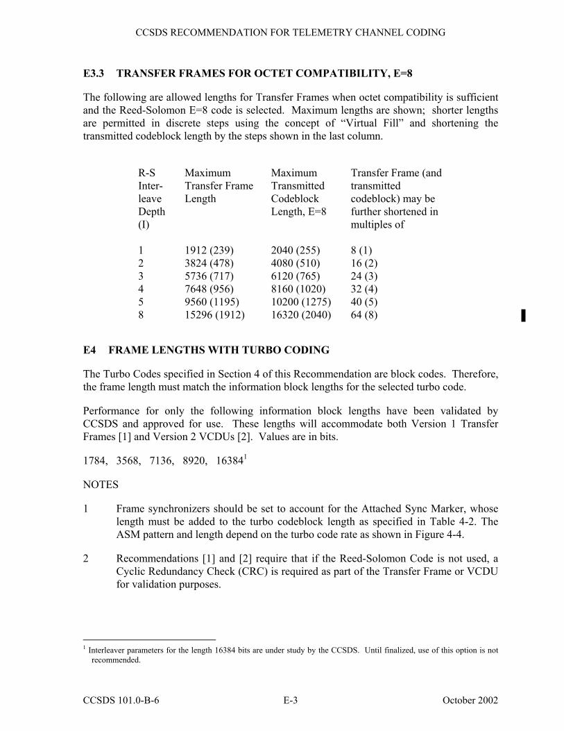
CCSDS RECOMMENDATION FOR TELEMETRY CHANNEL CODING
CCSDS 101.0-B-6 E-3 October 2002
E3.3 TRANSFER FRAMES FOR OCTET COMPATIBILITY, E=8
The following are allowed lengths for Transfer Frames when octet compatibility is sufficient and the Reed-Solomon E=8 code is selected. Maximum lengths are shown; shorter lengths are permitted in discrete steps using the concept of �Virtual Fill� and shortening the transmitted codeblock length by the steps shown in the last column.
R-S Inter- leave Depth (I)
Maximum Transfer Frame Length
Maximum Transmitted Codeblock Length, E=8
Transfer Frame (and transmitted codeblock) may be further shortened in multiples of
1 1912 (239) 2040 (255) 8 (1) 2 3824 (478) 4080 (510) 16 (2) 3 5736 (717) 6120 (765) 24 (3) 4 7648 (956) 8160 (1020) 32 (4) 5 9560 (1195) 10200 (1275) 40 (5) 8 15296 (1912) 16320 (2040) 64 (8)
E4 FRAME LENGTHS WITH TURBO CODING
The Turbo Codes specified in Section 4 of this Recommendation are block codes. Therefore, the frame length must match the information block lengths for the selected turbo code.
Performance for only the following information block lengths have been validated by CCSDS and approved for use. These lengths will accommodate both Version 1 Transfer Frames [1] and Version 2 VCDUs [2]. Values are in bits.
1784, 3568, 7136, 8920, 163841
NOTES
1 Frame synchronizers should be set to account for the Attached Sync Marker, whose length must be added to the turbo codeblock length as specified in Table 4-2. The ASM pattern and length depend on the turbo code rate as shown in Figure 4-4.
2 Recommendations [1] and [2] require that if the Reed-Solomon Code is not used, a Cyclic Redundancy Check (CRC) is required as part of the Transfer Frame or VCDU for validation purposes.
1 Interleaver parameters for the length 16384 bits are under study by the CCSDS. Until finalized, use of this option is not
recommended.