Switchgear Manual
88
ABB AS, Power Products Division SF 6 -insulated Ring Main Unit type SafeRing 12 - 24 kV and SF 6 -insulated Compact Switchgear type SafePlus 12 - 24 kV Product catalogue
-
Upload
duongquynh -
Category
Documents
-
view
302 -
download
7
Transcript of Switchgear Manual
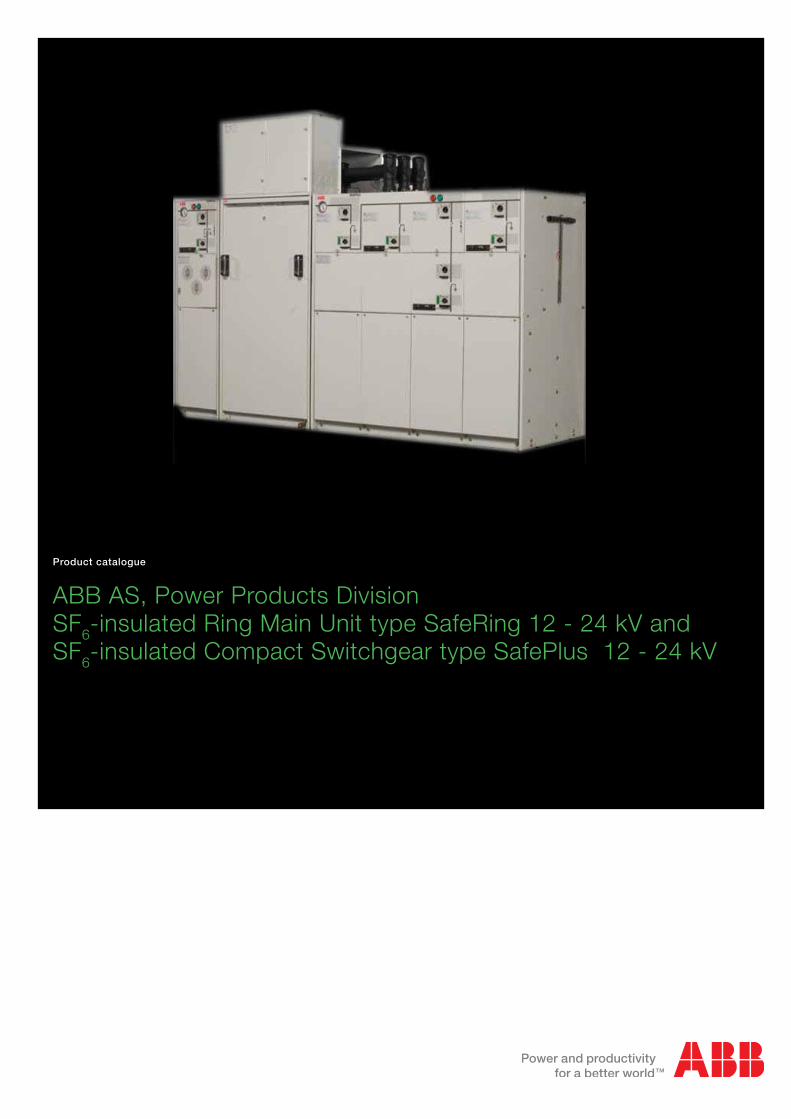
ABB AS, Power Products DivisionSF6-insulated Ring Main Unit type SafeRing 12 - 24 kV and SF6-insulated Compact Switchgear type SafePlus 12 - 24 kV
Product catalogue
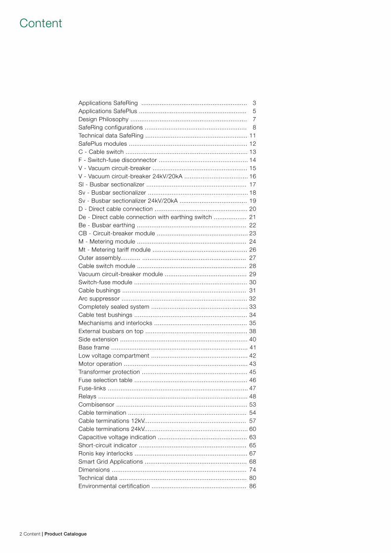
Content
Applications SafeRing .......................................................... 3Applications SafePlus ........................................................... 5Design Philosophy ................................................................ 7SafeRing configurations ........................................................ 8Technical data SafeRing ........................................................ 11SafePlus modules ................................................................. 12C - Cable switch ................................................................... 13F - Switch-fuse disconnector ................................................. 14V - Vacuum circuit-breaker .................................................... 15V - Vacuum circuit-breaker 24kV/20kA ................................... 16Sl - Busbar sectionalizer ....................................................... 17Sv - Busbar sectionalizer ....................................................... 18Sv - Busbar sectionalizer 24kV/20kA ..................................... 19D - Direct cable connection ................................................... 20De - Direct cable connection with earthing switch .................. 21Be - Busbar earthing ............................................................ 22CB - Circuit-breaker module .................................................. 23M - Metering module ............................................................ 24Mt - Metering tariff module .................................................... 26Outer assembly........... ......................................................... 27Cable switch module ............................................................ 28Vacuum circuit-breaker module ............................................. 29Switch-fuse module .............................................................. 30Cable bushings .................................................................... 31Arc suppressor ..................................................................... 32Completely sealed system ..................................................... 33Cable test bushings .............................................................. 34Mechanisms and interlocks ................................................... 35External busbars on top ........................................................ 38Side extension ...................................................................... 40Base frame ........................................................................... 41Low voltage compartment ..................................................... 42Motor operation .................................................................... 43Transformer protection .......................................................... 45Fuse selection table .............................................................. 46Fuse-links ............................................................................. 47Relays .................................................................................. 48Combisensor ........................................................................ 53Cable termination ................................................................. 54Cable terminations 12kV........................................................ 57Cable terminations 24kV......................................................... 60Capacitive voltage indication ................................................. 63Short-circuit indicator ........................................................... 65Ronis key interlocks .............................................................. 67Smart Grid Applications ........................................................ 68Dimensions .......................................................................... 74Technical data ...................................................................... 80Environmental certification .................................................... 86
2 Content | Product Catalogue
Applications SafeRing
SafeRing installed in Compact Secondary Substations
� � SafeRing � �� SafeRing
� � SafeRing
� � SafeRing
RMU type SafeRingCCV / CCF
RMU type SafeRingCCVV / CCFF
RMU type SafeRingCCCV / CCCF
RMU type SafeRingDeV / DeF
Product catalogue | Applications SafeRing 3
CCF
CCCF CCCV CCVVCCFF CCCC
CCVCCCDeF DeV
SafeRing is a ring main unit for the secondary distribution network. SafeRing can be supplied in 10 different configura-tions suitable for most switching applications in 12/24 kV distribution networks. It is extendible and combined with the SafePlus concept, which is ABB’s flexible, modular compact switchgear, they represent a complete solution for 12/24 kV secondary distribution networks. SafeRing and SafePlus have identical user interfaces.
SafeRing is a completely sealed system with a stainless steel tank containing all living parts and switching functions. A sealed steel tank with constant atmospheric conditions ensures a high level of reliability as well as personnel safety and a virtually maintenance-free system.
The SafeRing concept offers a choice of either a switch fuse combination or circuit breaker with relay for protection of the transformer. As the first ring main unit, SafeRing can be supplied complete with an integral remote control and monitoring unit.
SafeRing is designed for use in the following applications: – Compact secondary substations – Small industries – Wind power plants – Hotels, shopping centres, office buildings, business
centres etc. – Light mining applications, airports, hospitals, tunnels and
underground railways
Available modules:C Cable Switch De Direct Cable Connection with Earthing Switch F Switch Fuse-Disconnector V Vacuum Circuit-Breaker
Applications SafeRing
4 Applications SafeRing | Product Catalogue
A
V
3
3
3
3
3
M
M
3
C
Sl Sv
CBDe
Be M Mt
D F V
SafePlus is designed for use in the following applications: – Compact secondary substations – Small industries – Wind power plants – Hotels, shopping centres, office buildings, business
centres etc. – Light mining applications, airports, hospitals, tunnels and
underground railways
Available modules:C Cable SwitchDe Direct Cable Connection with earthingD Direct Cable ConnectionF Switch-Fuse DisconnectorV Vacuum Circuit breakerBe Busbar earthingSl Busbar Sectionalizer, load break switchSv Busbar Sectionalizer, vacuum circuit breakerCB Circuit-breaker moduleM Metering ModuleMt Metering tariff module
Applications SafePlus
Product catalogue | Applications SafePlus 5
SafePlus� ��� �� � �� SafePlus� �� SafePlus� �� � ��SafePlusSafePlusSafePlus
� �� REF541 � �� REF541 � �� REF541
C C V V V C
� ��SafePlus
� ��SafePlusSafePlus
� ��
CC M FF
SafePlus compact switchgear consisting of: – 2-ways section with 2 modules of cable switches – air-insulated metering module – 2-ways section with 2 modules of switch fuses
SafePlus compact switchgear in fully modular design consisting of: – 3 modules of cable switches – 3 modules of vacuum circuit breakers in combination with
REF relays
Applications SafePlus
6 Applications SafePlus | Product Catalogue
SafeRing and SafePlus – ABB switchgear for secondary distribution Secondary distribution switchgears have been subject to a significant development the past 20 years,resulting in increased functionality and smaller dimensions.
The traditional switching cells are substituted with complete switchgear systems. Specific functions as grounding, discon-necting, cable connections, busbar extension, protection and switching have become integrated features in compact functional units.
Compact switchgear systems meet customers MV application needs. ABB has always been a part of this development.
The current ABB SafePlus range satisfies the most complex system specifications.
The most unique specialisation is the development of the cable ring switchgear. The numerous public distribution substations requested a unified switching functionality which evolved into the Ring Main Unit concept.
ABB SafeRing range is one major contributor to this specialisation.
Two Products – One rangeABB SafeRing is adapted to the needs in the immense utility distribution network.ABB SafePlus offers more in terms of flexibility and electrical capacity.Both switchgear offer the same customer interface.
Customers’ involvementThe applied functionality in ABB SafeRing and SafePlus is a result of input from customers all over the world. Key customers are continuously involved with ABB design staff to ensure optimized switchgear operation. The functio-nality will always find its background from customer demands.
Personnel – safety and serviceSafety is not only a specification and rating issue, but also a real life experience.Standards and associated testing will disclose weakness at time of testing. ABB takes this further to be an objective related to durability and repetitive manufacturing quality.
All products are manufactured in accordance with ISO 9001.The latest edition of relevant IEC standards will always apply to our continuous product development and test program.“Integrated functionality” is a key objective to reduce the number of moving components, further reducing the risk of any mechanical defect.
We are responsible for the environmentThe location for manufacturing SafeRing and SafePlus is Norway. Norway’s green policy contributes to focus on environmental factors in manufacturing as well as over the switchgears life span.
All products are manufactured in accordance with our ISO 14001 certification.Recycling is confirmed at a 97% level. To simplify this process we will continuously along with our partners develop routines for handling at end of life. Plastic parts are individually marked to simplify the recycling process.
Solutions for elimination of gas emission in the rare event of a fault can be supplied.
Modern - development and manufacturingNumerical simulations together with long experience will ensure compact and robust design.
Dielectric simulations will ensure that compactness will not influence the dielectric capability.
The combination of design techniques, experience and the most modern production technology guarantee state of the art products and durability.
Complete solutions – one supplierComplex applications involving remote control and monitoring can now be supplied from one supplier.
This makes large scale implementation feasible, and will simplify engineering and procurement.The control and monitoring unit available for SafeRing is located behind the front cover. This option is also readily avail-able for retrofit, while such demands normally evolve after the switchgear is in service.
Design philosophy
Product catalogue | Design philisophy 7
GeneralSafeRing is a ring main unit for the secondary distribution network. SafeRing can be supplied in 10 different configura-tions suitable for most switching applications in 12/24 kV distribution networks. SafeRing can as an option be delivered as extendable rong main unit.
SafeRing combined with the SafePlus concept, which is ABB’s flexible, modular compact switchgear represent a com-plete solution for 12/24 kV secondary distribution networks. SafeRing and SafePlus have identical user interfaces.
SafeRing is a completely sealed system with a stainless steel tank containing all the live parts and switching functions. A sealed steel tank with constant atmospheric conditions en-sures a high level of reliability as well as personnel safety and a virtually maintenance-free system.
The SafeRing concept offers a choice of either a switch fuse combination or circuit breaker with relay for protection of the transformer. SafeRing can be supplied with an integrated remote control and monitoring unit.
SafeRing is supplied with the following standard equipment – Earthing switches – Operating mechanisms with integral mechanical inter-
locking – Operating handle – Facilities for padlocks on all switching functions – Bushings for cable connection in front with cable covers – Lifting lugs for easy handling – All 3- and 4-way units are designed for the subsequent
fitting of an integral remote control and monitoring unit
Optional features – Bushings for connection of external busbar on top of RMU – Bushings for side connection (400A) (C-, F- and De-
modules only) – Bushings for cable testing, incl. earthing device (C- and
De- modules only) – Cable bushings (Interface A, B, C and D) – Cable compartment front cover interlocked with earthing
switch – Interlocking of compartment for cable test bushings – Arc suppressor with signal (1NO) wired to terminals
(only one each SF6 tank) – Signal (1NO) from internal pressure indicator wired to
terminals (only one each SF6 tank) – Latched single spring mechanism for ring cable switch
Optional features also available as retrofit – Manometer for SF6 pressure monitoring
(temperature compensated) – Integrated control and monitoring unit (ICMU) – Integrated battery and charger
– Motor operation – Trip coil open – Trip coil open and close
– Aux. switch for load break switch position 2NO + 2NC – Aux. switch for vacuum circuit breaker position
2NO + 2NC – Aux. switch for disconnected position 2NO + 2NC – Aux. switch for earth switch position 2NO + 2NC – Aux. switch for fuse blown 1NO – Vacuum circuit breaker tripped signal 1NO
– Capacitive voltage indicating system – Short circuit indicator
– Cable cover with window – Cable cover for double T – Arc proof cable compartment
– Extra base frame (h=450 mm or 290 mm) – Top entry box – Cable support bars, non-magnetic or adjustable – Ronis interlocking system, EL 11 AP – Current measuring – Prepared for relay test equipment
SafeRing configurations
8 SafeRing configurations | Product Catalogue
� �� SafeRing
� ��SafeRing
� ��SafeRing
� ��SafeRing
� �� SafeRing DeFDepth: 765 mmWidth: 696 mmHeight: 1336 mm
CCFDepth: 765 mmWidth: 1021 mmHeight: 1336 mm
CCCFDepth: 765 mmWidth: 1346 mmHeight: 1336 mm
CCFFDepth: 765 mmWidth: 1346 mmHeight: 1336 mm
DeVDepth: 765 mmWidth: 696 mmHeight: 1336 mm
SafeRing configurations
Product catalogue | SafeRing configurations 9
� ��SafeRing
� ��SafeRing
� ��SafeRing
� ��SafeRing
� ��SafeRing CCV
Depth: 765 mmWidth: 1021 mmHeight: 1336 mm
CCCVDepth: 765 mmWidth: 1346 mmHeight: 1336 mm
CCVVDepth: 765 mmWidth: 1346 mmHeight: 1336 mm
CCCDepth: 765 mmWidth: 1346 mmHeight: 1336 mm
CCCCDepth: 765 mmWidth: 1346 mmHeight: 1336 mm
SafeRing configurations
10 SafeRing configurations | Product Catalogue
SafeRing is tested according to IEC publications IEC 60265-1, IEC 6227-1, EC 62271-100, -102, -105, -200 and IEC 60529.
1) Depending on the current rating of the fuse-link2) Limited by high voltage fuse-links 3) Maximum rating for bushings Interface A (200 series plug-in) 4) Maximum rating for bushings Interface B (400 series plug-in) 5) Maximum rating for bushings Interface C (400 series bolted)
SafeRing C-module F-module V-module
Switch
disconnector
Earthing switch Switch-fuse
disconnector
Downstream
earthing switch
Vacuum
circuit-breaker
Earthing
switch/
disconnector
Rated voltage kV 12/15/17,5/24 12/15/17,5/24 12/17,5/24 12/17,5/24 12/15/17,5/24 12/15/17,5/24
Power frequency withstand voltage kV 28/38/38/50 28/38/38/50 28/38/50 28/38/50 28/38/38/50 28/38/38/50
Lightning impulse withstand voltage kV 95/95/95/125 95/95/95/125 95/95/125 95/95/125 95/95/95/125 95/95/95/125
Rated normal current A 630/630/630/630 see1) 200/200/200/200
Breaking capacities:
- active load A 630/630/630/630
- closed loop A 630/630/630/630
- off load cable charging A 135/135/135/135
- off load transformer A 20/20/20
- earth fault A 200/150/150/150
- earth fault cable charging A 115/87/87/87
- short-circuit breaking current kA see2) 16/16/16/16
Making capacity kA 52,5/52,5/40/40 52,5/52,5/40/40 see2) 12,5/12,5/12,5 40/40/40/40 40/40/40/40
Short time current 0,5 sec. 3) kA 16/16/16/16
Short time current 1 sec. 4) kA 16/16/16 5/5/5 16/16/16/16
Short time current 3 sec. 5) kA 21/21/16/16 21/21/16/16 16/16/16/16 16/16/16/16
Technical data SafeRing
Product catalogue | Technical data SafeRing 11
General SafePlus is a metal enclosed compact switchgear system for up to 24 kV distribution applications. The switchgear has a unique flexibility due to its extendibility and the possible com-bination of fully modular and semi-modular configurations.
SafePlus combined with SafeRing, which is ABBs standard ring main unit, represent a complete solution for 12/24 kV distribution networks. SafePlus and SafeRing have identical user interfaces.
SafePlus is a completely sealed system with a stainless steel tank containing all live parts and switching functions.
A sealed steel tank with constant atmospheric conditions ensures a high level of reliability as well as personnel safety and a virtually maintenance-free system. As an option external busbars can be provided to obtain full modularity. The external busbar kit has to be mounted to the switchgears on site. It is fully insulated and screened to ensure the relia-bility and climatic independence.
The SafePlus system offers a choice of either a switch-fuse combination or a circuit-breaker with relay for protection of the transformer. SafePlus accommodates a wide selection of protection relays for most applications.SafePlus can also be supplied with remote control and moni-toring equipment
SafePlus (except M- and Mt-modules) is supplied with the following standard equipment: – Earthing switches (not for D module) – Operating mechanisms with integral mechanical
interlocking – Operating handle – Facilities for padlocks on all switching functions – Bushings for cable connection in front (not for Sl, Sv and
Be modules) – Cable compartment cover – Manometer for SF6 pressure monitoring (temperature
compensated) – Lifting lugs for easy handling
SafePlus modules
12 SafePlus modules | Product Catalogue
Depth: 765 mmWidth: 325 mmHeight: 1336 mm
Standard features – Three position load break switch with disconnector and
earthing switch – Operating mechanism with two separate operating shafts
for load break function and earthing function – Switch position indication for load break switch and
earthing switch – Cable bushings horizontal in front, Interface C (400 series
bolted) with integrated voltage divider for voltage indication – Cable compartment cover allowing surge arrestor or
double cable connection – Busbar, 630A – Earthing bar
Optional features – Bushings for connection of external busbar on top of the
unit – Bushings for side extension (400 A) – Bushings for cable testing (incl. earthing device test points) – Cable bushings:
Interface B (400 series plug-in, In = 400 A) Interface C (400 series bolted) combisensors with integrated capacitor for voltage indication and sensors for current and voltage monitoring Interface D (600 series bolted) – Cable compartment front cover interlocked with earthing
switch – Interlocking of compartment for cable test bushings – Arc proof and interlocked cable covers – Arc suppressor with signal (1NO) wired to terminals
(only one each SF6 tank)
Technical dataSwitch disconnectorRated voltage kV 12 15 17,5 24Power frequency withstand voltage kV 28 38 38 50Impulse withstand voltage kV 95 95 95 125Rated normal current A 630 630 630 630Breaking capacities:- active load A 630 630 630 630- closed loop A 630 630 630 630- off load cable charging A 135 135 135 135- earth fault A 200 150 150 150- earth fault cable charging A 115 87 87 87Making capacity kA 62,5 52,5 50 50 Short time current 1 sec. kA 25 - - -Short time current 3 sec. kA 21 21 21 21Number of mechanical operations 1000 close / open manualEarthing switchRated voltage kV 12 15 17,5 24Power frequency withstand voltage kV 28 38 38 50Impulse withstand voltage kV 95 95 95 125Making capacity kA 62,5 52,5 50 50 Short time current 1 sec. kA 25 - - -Short time current 3 sec. A 21 21 21 21Number of mechanical operations 1000 close / open manual
– Signal (1NO) from internal pressure indicator wired to terminals (only one each SF6 tank) – Latched single spring mechanism
Optional features also available as retrofit – Motor operation for load break switch – Low voltage compartment / top entry box – Base frame (290 or 450 mm) – Auxiliary switches for load break switch position and
earthing switch position – Capacitive voltage indicator, HR-module (Voltage
Detecting System, VDS), acc. to IEC 61243 -5, or VPIS, acc. to IEC 61958 with integrated indicator lamps (LED) – Indicator lamps, 3-phase VIM-3 – Indicator lamp, 1-phase VIM-1 – Short circuit indicators – Short circuit and earth fault indicators – Ronis key interlock – External current sensors (CT) for monitoring – Cable compartment cover with window, with extra depth
(double T, surge arrestors) and arc proof (if existing module have interlocked cable compartment – Cable support bars, non-magnetic or adjustable – Earthing bar for surge arrestor
C - Cable switch
Product catalogue | C - Cable switch 13
Technical dataSwitch-fuse-disconnectorRated voltage kV 12 15 17,5 24Power frequency withstand voltage kV 28 38 38 50Impulse withstand voltage kV 95 95 95 125Rated normal current A 200 200 200 200Breaking capacities:- off load transformer A 20 20 20 20Making capacity kA 1) 1) 1) 1) Number of mechanical operations 1000 close / open manualEarthing switch downstreamRated voltage kV 12 15 17,5 24Power frequency withstand voltage kV 28 38 38 50Impulse withstand voltage kV 95 95 95 125Making capacity kA 12,5 12,5 12,5 12,5 Short time current 1 sec. kA 5 5 5 5Number of mechanical operations 1000 close / open manual
Standard features – Three position switch-fuse-disconnector with upstream
earthing switch mechanically linked with downstream earthing switch – Switch position indication for switch-fuse-disconnector and
earthing switches – Operating mechanism with double spring for switch-fuse-
disconnector function – Common mechanism for earthing functions – Fuse canisters for DIN type fuse. Only accessible when
earthing switches are closed – Fuse-link / transformer rating:
12 kV, max 125 A CEF fuses 24 kV, max 63 A CEF fuses – Fuse tripping arrangement – Optical fuse trip indication – Cable bushings horizontal in front, Interface A (200 series
plug-in) with integrated capacitor for voltage indication – Cable compartment cover allowing surge arrestor or
double cable connection – Busbar, 630 A – Earthing bar
Optional features – Bushings for connection of external busbar on top of unit – Bushings for side extension (400 A) – Cable bushings:
Interface B (400 series plug-in, In = 400A) Interface C (400 series bolted) Interface C (400 series bolted) combisensors with in tegrated screen for voltage indication and sensors for current and voltage monitoring
Depth: 765 mmWidth: 325 mmHeight: 1336 mm
– Cable compartment front cover interlocked with earthing switch – Signal (1NO) from internal pressure indicator wired to
terminals (only one each SF6 tank)
Optional features also available as retrofit – Motor operation for switch-fuse-disconnector – Low voltage compartment/top entry box – Base frame (290 or 450 mm) – Auxiliary switches for load break switch position, earthing
switch position and fuse blown – Capacitive voltage indicator, HR-module (Voltage
Detecting System, VDS), acc. to IEC 61243 -5, or VPIS, acc. to IEC 61958 with integrated indicator lamps (LED) – Indicator lamps, 3-phase VIM-3 – Indicator lamp, single phase VIM-1 – Trip coil open – Trip coil open and close – Cable compartment cover with window, with extra depth
(double T, surge arrestors) and arc proof (if existing module have interlocked cable compartment) – Cable support bards, non-magnetic or adjustable – Earthing bar for surge arrestor – Ronis key interlock on earthing switch
1) Limited by high voltage fuse-links
F - Switch-fuse-disconnector
14 F - Switch-fuse-disconnector | Product Catalogue
Standard features – 200 A vacuum circuit-breaker for transformer protection or
630 A vacuum circuit-breaker for feeder protection – Two position double spring mechanism for vacuum circuit-
breaker – Three position disconnector/earthing switch downstream
vacuum circuit-breaker – Three positioning single spring mechanism for
disconnector/earthing switch – Interlocking between vacuum circuit-breaker and
disconnector/earthing switch – Switch positioning indication for vacuum circuit-breaker
and disconnector/earthing switch – Self powered electronic protection relay with ring core CTs
on cables (only standard on 200 A) – Trip coil (for relay tripping) – Cable bushings horizontally in front; Interface A (200 series
plug-in) for 200 A vacuum circuit-breaker with integrated capacitor for voltage indication and Interface C (400 series bolted) for 630 A vacuum circuit-breaker with integrated capacitor for voltage indication – Cable compartment cover allowing surge arrestor or
double cable connection – Busbars, 630 A – Earthing bar
Optional features – Bushings for connection of external busbar on top of unit – Cable bushings:
Interface B (400 series plug-in) Interface D (600 series bolted)
Depth: 765 mmWidth: 325 mmHeight: 1336 mm
Technical dataVacuum circuit-breakerRated voltage kV 12 15 17,5 24Power frequency withstand voltage kV 28 38 38 50Impulse withstand voltage kV 95 95 95 125Rated normal current A 200 / 630Breaking capacities:- short-circuit breaking current kA 21 21 16 16Making capacity kA 52,5 52,5 40 40 Short time current 0,5 sec. 1) kA 16 16 16 16Short time current 1 sec. 2) 16 16 16 16Short time current 3 sec. kA 21 21 16 16Number of mechanical operations 2000 close / open manualEarthing switch downstreamRated voltage kV 12 15 17,5 24Power frequency withstand voltage kV 28 38 38 50Impulse withstand voltage kV 95 95 95 125Making capacity kA 52,5 52,5 40 40 Short time current 3 sec. A 21 21 16 16Number of mechanical operations 1000 close / open manual
Interface C (400 series bolted) combisensors with integrated voltage divider for voltage indication and integrated sensor for current and voltage monitoring – Cable compartment front cover interlocked with earthing
switch – Arc suppressor (for 630 A vacuum circuit-breaker only)
with signal (1NO) wired to terminals (only one each SF6 tank) – Signal (1NO) from internal pressure indicator wired to
terminals (only one each SF6 tank)
Optional features also available as retrofit – Motor operation for vacuum circuit-breaker – Low voltage compartment / Top entry box – Base frame (290 or 450 mm) – Auxiliary switches; Vacuum circuit breaker position
2NO+2NC, disconnector position 2NO+2NC, earthing switch position 2NO+2NC and vacuum circuit-breaker tripped signal 1NO – Capacitive voltage indicator; HR-module (Voltage
Detecting System, VDS, acc. to IEC 61243 -5, or VPIS, acc. to IEC 61958 with integrated indicator lamps (LED) – Indicator lamps, 3-phase VIM-3 – Indicator lamp, 1-phase VIM-1 – Trip coil open – Trip coil open and close – Cable compartment cover with window, with extra depth
(double T, surge arrestors) or arc proof (if existing module has interlocked cable compartment) – Cable support bars, non-magnetic – Ronis key interlock on disconnector / earthing switch – Advanced relays type SPAJ, REF and others.
1) Maximum rating for bushings Interface A (200 series plug-in) with rated curretn 200 A2) Maximum rating for bushings Interface B (400 series plug-in)
V - Vacuum circuit-breaker
Product catalogue | V - Vacuum circuit-breaker 15
� �� REJ603
16 V - Vacuum circuit-breaker | Product Catalogue
V - Vacuum circuit-breaker - 24kV/20kA
Technical data
Vacuum circuit-breakerRated voltage kV 24Power frequency withstand voltage kV 50Impulse withstand voltage kV 125Rated normal current A 630Breaking capacities:- short-circuit breaking current kA 20Making capacity kA 50 Short time current 1 sec. 1) kA 21Short time current 3 sec. kA 21Number of mechanical operations 2000 close / open manualEarthing switch downstreamRated voltage kV 24Power frequency withstand voltage kV 50Impulse withstand voltage kV 125Making capacity kA 50 Short time current 1 sec. A 21Number of mechanical operations 1000 close / open manual
1) Maximum rating for bushings Interface B (400 series plug-in): 16kA
Standard features – 630 A vacuum circuit-breaker for feeder protection – Mechanism with operating sequence;
O – 0,3 s – CO – 3 min – CO – Auto-reclosing capability – Vacuum circuit-breaker with downstream three-position
disconnector/earthing switch – Three-position single spring mechanism for
disconnector/earthing switch – Interlocking between vacuum circuit-breaker and
disconnector/earthing switch – Switch position indication for vacuum circuit-breaker
and disconnector/earthing switch – Mechanical counter – Self-powered electronic protection relay with ring core CTs
on cables – Trip coil (for relay tripping) – Cable bushings horizontally in front Interface C (400 series
bolted) with integrated capacitor for voltage indication – Cable compartment cover allowing surge arrestor or
double cable connection – Busbars, 630 A – Earthing bar
Optional features as factory mounted – Bushings for connection of external busbar on top of unit – Cable bushings:
Interface B (400 series plug-in) Interface C (400 series bolted) combisensors with integrated voltage divider for voltage indication and integrated sensor for current and voltage monitoring
– Cable cover interlocked with earthing switch – Arc proof cable cover (IAC AFL 16/20 kA 1 sec.) – Arc suppressor with signal (1NO) wired to terminals
(only one each SF6 tank) – Height 1100 mm
Optional features also available as retrofit – Motor operation for vacuum circuit-breaker – Low voltage compartment / Top entry box – Manometer with integrated signal for low gas pressure
wired to terminals (only one each SF6 tank) – Base frame (290 or 450 mm) – Auxiliary switches: Vacuum circuit breaker position
2NO+2NC, disconnector position 2NO+2NC, earthing switch position 2NO+2NC – Capacitive voltage indicator: – HR-module (VDS, acc. to IEC 61243 -5) – VPIS, acc. to IEC 61958 with integrated indicator lamps
(LED) – Indicator lamps, 3-phase VIM-3 – Indicator lamp, 1-phase VIM-1 – Trip coil open – Trip coil open and close – Undervoltage coil with/without time delay – Blocking magnet to prevent unintended operation – Cable compartment cover
with window with extra depth (double T, surge arrestors) – Cable support bars, non-magnetic – Ronis key interlock on disconnector / earthing switch – Advanced relays type REF, REX and others
Depth: 765 mmWidth: 325 mmHeight: 1336 mm (optional 1100 mm)
Technical dataBusbar sectionalizer SlRated voltage kV 12 15 17,5 24Power frequency withstand voltage kV 28 38 38 50Impulse withstand voltage kV 95 95 95 125Rated normal current A 630 630 630 630Breaking capacities:- active load A 630 630 630 630- closed loop A 630 630 630 630- off load cable charging A 135 135 135 135- earth fault A 200 150 150 150- earth fault cable charging A 115 87 87 87Making capacity kA 62,5 52,5 50 50 Short time current 1 sec. kA 25 - - -Short time current 3 sec. kA 21 21 21 21Number of mechanical operations 1000 close / open manualEarthing switchRated voltage kV 12 15 17,5 24Power frequency withstand voltage kV 28 38 38 50Impulse withstand voltage kV 95 95 95 125Rated normal current A 630 630 630 630Making capacity kA 62,5 52,5 50 50 Short time current 1 sec. kA 25 - - -Short time current 3 sec. A 21 21 21 21Number of mechanical operations 1000 close / open manual
Standard features – Three positioning load break switch with disconnector and
earthing switch – Operating mechanism with two separate operating shafts
for load break function and earthing function – Switch position indication for load break switch and
earthing switch – Busbars, 630 A – Earthing bar
Optional features – Bushings for connection of external busbars on top of the
unit – Latched single spring mechanism
Depth: 765 mmWidth: 325 mmHeight: 1336 mm
Depth: 765 mmWidth: 650 mmHeight: 1336 mm
Busriser is needed when Sl-module is on right hand side of SF6-tank
Optional features also available as retrofit – Motor operation for load break switch – Low voltage compartment/Top entry box – Manometer with integrated signal for low gas pressure
wired to terminals (only one each SF6 tank) – Base frame (290 or 450 mm) – Auxiliary switches, load break switch position 2NO+2NC
and earthing switch position 2NO+2NC – Ronis key interlock
Sl - Busbar sectionalizer
Product catalogue | Sl - Busbar sectionalizer 17
Technical dataBusbar sectionalizer SvRated voltage kV 12 15 17,5 24Power frequency withstand voltage kV 28 38 38 50Impulse withstand voltage kV 95 95 95 125Rated normal current A 630 630 630 630Breaking capacities:- short-circuit breaking ccurrent kA 21 21 16 16Making capacity kA 52,5 52,5 40 40 Short time current 3 sec. kA 21 21 16 16Number of mechanical operations 2000 close / open manualEarthing switchRated voltage kV 12 15 17,5 24Power frequency withstand voltage kV 28 38 38 50Impulse withstand voltage kV 95 95 95 125Making capacity kA 52,5 52,5 40 40 Short time current 3 sec. A 21 21 16 16Number of mechanical operations 1000 close / open manual
Standard features – 630 A vacuum circuit-breaker – Two position double spring mechanism for vacuum circuit-
breaker – Three position disconnector / earthing switch downstream
vacuum circuit-breaker – Three position single spring mechanism for disconnector /
earthing switch – Interlocking between vacuum circuit-breaker and
disconnector / earthing switch – Switch position indication for vacuum circuit-breaker and
disconnector / earthing switch – Busbars, 630 A
Optional features – Bushings for connection of external busbar
Depth: 765 mmWidth: 650 mmHeight: 1336 mm
Sv is always in combination with busrise module (Br)
Optional features also available as retrofit – Motor operation for vacuum circuit-breaker – Low voltage compartment / Top entry box – Manometer with integrated signal for low gas pressure
wired to terminals (only one each SF6 tank) – Base frame (290 or 450 mm) – Auxiliary switches, vacuum circuit-breaker position
2NO+2NC, disconnector position 2NO+2NC and earthing switch position 2NO+2NC – Protection relay (metering module is required) – Trip coil for relay trip – Additional trip coil – Ronis key interlock on disconnector / earthing switch
Sv - Busbar sectionalizer
18 Sv - Busbar sectionalizer | Product Catalogue
� �� REJ603
Standard features – 630 A vacuum circuit-breaker – Mechanism with operating sequence;
O – 0,3 s – CO – 3 min – CO – Vacuum circuit-breaker with downstream three-position
disconnector/earthing switch – Three position single spring mechanism for disconnector /
earthing switch – Interlocking between vacuum circuit-breaker and
disconnector / earthing switch – Switch position indication for vacuum circuit-breaker and
disconnector / earthing switch – Busbars, 630 A
Optional features – Bushings for connection of external busbar
Depth: 765 mmWidth: 650 mmHeight: 1336 mm
Sv is always in combination with busrise module (Br)
Optional features also available as retrofit – Motor operation for vacuum circuit-breaker – Low voltage compartment / Top entry box – Manometer with integrated signal for low gas pressure
wired to terminals (only one each SF6 tank) – Base frame (290 or 450 mm) – Auxiliary switches, vacuum circuit-breaker position
2NO+2NC, disconnector position 2NO+2NC and earthing switch position 2NO+2NC – Protection relay (metering module is required) – Trip coil for relay trip – Additional trip coil – Ronis key interlock on disconnector / earthing switch
Sv - Busbar sectionalizer - 24kV/20kA
Product catalogue | Sv - Busbar sectionalizer 19
Technical dataBusbar sectionalizer SvRated voltage kV 24Power frequency withstand voltage kV 50Impulse withstand voltage kV 125Rated normal current A 630Breaking capacities:- short-circuit breaking ccurrent kA 20Making capacity kA 50 Short time current 3 sec. kA 21Number of mechanical operations 2000 close / open manualEarthing switchRated voltage kV 24Power frequency withstand voltage kV 50Impulse withstand voltage kV 125Making capacity kA 50 Short time current 3 sec. A 21Number of mechanical operations 1000 close / open manual
Technical dataDirect cable connectionRated voltage kV 12 15 17,5 24Power frequency withstand voltage kV 28 38 38 50Impulse withstand voltage kV 95 95 95 125Rated normal current A 630 630 630 630Short time current 1 sec. kA 25 - - -Short time current 3 sec. kA 21 21 21 21
Depth: 765 mmWidth: 325 mmHeight: 1336 mm
Standard features – Cable bushings horizontally in front, Interface C (400 series
bolted) with integrated capacitor for voltage indication. – Cable compartment cover allowing surge arrestor or
double cable connection – Busbars, 630 A – Earthing bar
Optional features – Bushings for connection of external busbars – Cable bushings:
Interface B (400 series plug-in) (In = 400 A) Interface C (400 series bolted) combisensors with integrated capacitor for voltage indication and sensors for current and voltage monitoring Interface D (600 series bolted) – Arc suppressor with signal (1NO) wired to terminals
(only one each SF6 tank) – Signal (1NO) from internal pressure indicator wired to
terminals (only one each SF6 tank)Optional features also available as retrofit – Low voltage compartment / top entry box – Base frame (290 or 450 mm) – Capacitive voltage indicating systems, HR-module (Voltage
Detecting System, VDS, acc. to IEC 61243 -5, or VPIS, acc. to IEC 61958 with integrated indicator lamps (LED) – Indicator lamps for HR-module, 3-phase VIM-3 – Indicator lamp for HR-module, 1-phase VIM-1 – Short circuit indicators – Earth fault indicators – External current sensors (CT) for monitoring – Cable compartment cover with window, with extra depth
(double T, surge arrestors) or arc proof (if existing module has interlocked cable compartment) – Cable support bars, non-magnetic or adjustable – Earth bar for surge arrestor
D - Direct cable connection
20 D - Direct cable connection | Product Catalogue
Technical dataDirect cable connection with earthing switchRated voltage kV 12 15 17,5 24Power frequency withstand voltage kV 28 38 38 50Impulse withstand voltage kV 95 95 95 125Rated normal current A 630 630 630 630Making capacity kA 62,5 52,5 50 50 Short time current 1 sec kA 25Short time current 3 sec. kA 21 21 21 21Number of mechanical operations 1000 close / open manual
Depth: 765 mmWidth: 325 mmHeight: 1336 mm
Standard features – Earthing switch – Two positioning single spring mechanism – Switch position indication – Cable bushings horizontal in front, Interface C (400 series
bolted) with integrated capacitor for voltage indication – Cable compartment cover allowing surge arrestor or
double cable connection – Busbars, 630 A – Earthing bar
Optional features – Bushings for connection of external busbars – Bushings for cable testing, incl. earthing device – Cable bushings:
Interface B (400 series plug-in) (In = 400 A) Interface C (400 series bolted) combisensors with integrated capacitor for voltage indication and sensors for current and voltage monitoring Interface D (600 series bolted) – Cable compartment front cover interlockied with earthing
switch – Interlocking of compartment for cable test bushings – Arc suppressor with signal (1NO) wired to terminals (only
one each SF6 tank) – Signal (1NO) from internal pressure indicator wired to
terminals (only one each SF6 tank)
Optional features also available as retrofit – Low voltage compartment / Top entry box – Base frame (290 or 450 mm) – Capacitive voltage indicating systems, HR-module (Voltage
Detecting System, VDS, acc. to IEC 612-43-5, or VPIS, acc. to IEC 61958 with integrated indicator lamps (LED) – Indicator lamps for HR-module, 3-phase VIM-3 – Indicator lamp for HR-module, 1-phase VIM-1 – Short circuit indicators – Earth fault indicators External current sensors (CT) for
monitoring – Cable compartment cover with window, with extra depth
(double T, surge arrestors) and arc proof (if existing module has interlocked cable compartment) – Cable support bars, non-magnetic or adjustable – Earth bar for surge arrestor – Auxiliary switches, earthing switch position 2NO+2NC – Ronis key interlock
De - Direct cable connection with earthing switch
Product catalogue | De - Direct cable connection with earthing switch 21
Technical dataBusbar earthingRated voltage kV 12 15 17,5 24Power frequency withstand voltage kV 28 38 38 50Impulse withstand voltage kV 95 95 95 125Rated normal current A 630 630 630 630Making capacity kA 62,5 52,5 50 50 Short time current 1 sec kA 25Short time current 3 sec. kA 21 21 21 21Number of mechanical operations 1000 close / open manual
Depth: 765 mmWidth: 325 mmHeight: 1336 mm
Standard features – Earthing switch – Two position single spring mechanism – Switch position indication for earthing switch – Busbars, 630 A – Earthing bar
Optional features – Bushings for connection of external busbars – Signal (1NO) from internal pressure indicator wired to ter
minals (only one each SF6 tank)
Optional features also available as retrofit – Low voltage compartment / Top entry box – Base frame (290 or 450 mm – Auxiliary switches, earthing switch position 2NO+2NC – Ronis key interlock
Be - Busbar earthing
22 Be - Busbar earthing | Product Catalogue
M
M
3
VD4
SafePlus� ��
� �� REF541
Technical dataCircuit-breaker moduleRated voltage kV 12 24Power frequency withstand voltage kV 28 50Impulse withstand voltage kV 95 125Rated normal current A 630 / 1250 630 / 1250Breaking capacities: Short-circuit breaking current kA 25 20Making capacity kA 62,5 50 Short time current 1 sec kA 25 20Short time current 3 sec. kA 25 20Number of mechanical operations 30000 close / open manual
Depth: 800 mmWidth: 696 mmHeight: 1336 mm
Standard features – 630/1250A vacuum circuit breaker – Disconnector – Earthing switch – Bushings for connection of external busbars – Auto reclosing sequence – Closing and tripping coil – Combisensors with Interface C (400 series bolted) – Low voltage compartment with different protection relays
Optional features – Signal (1NO) from internal pressure indicator wired to
terminals
Optional features also available as retrofit – Base frame (290 or 450 mm) – Motor operated disconnector / earthing switch – Motor operating mechanism, circuit-breaker
A selection of configurable functions
Protection: – non-directional overcurrent protection, 3 stages – directional overcurrent protection, 3 stages – non-directional earth-fault protection – directional earth-fault protection – residual overvoltage protection – 3-phase thermal overload – 3-phase overvoltage protection – under- or overfrequency incl. rate of change, 5 stages
Measurement: – 3-phase current – neutral current – 3-phase voltage – residual voltage – 3-phase power and energy incl. cos phi – transient disturbance recorder
Optional functionality – Capacitor bank protection – Capacitor bank control – Power quality – Auto changeover
CB - Circuit-breaker module
Product catalogue | CB - Ciscuit-breaker module 23
A
3
3
V
� ��SafePlus
Technical dataMetering moduleRated voltage kV 12 15 17,5 24Power frequency withstand voltage kV 28 38 38 50Impulse withstand voltage kV 95 95 95 125Rated normal current A 630 630 630 630Short time current 1 sec kA 25Short time current 3 sec. kA 21 21 21 21
The M-module is a factory assembled type tested air insu-lated metering cubicle with conventional CTs and VTs. The M-module is designed for CTs and VTs with dimensions ac-cording to DIN 42600 Narrow type. The M-module is also designed for tariff metering.
Depth: 802 mmWidth: 696 mmHeight: 1806 mm
Standard features – 2 or 3 pcs (has to be specified) DIN 42600 Narrow type
current transformers with ribs – 3 pcs DIN 42600 Narrow type single pole voltage trans
formers – 6 pcs bushings Interface C (400 series bolted) with con
nections and external busbars for SafePlus modules on left and right hand side – 3 pcs bushings Interface C (400 series bolted) only re
quired if the M-module is left hand side or right hand side end module – Internal layout with CTs and VTs on left hand side or right
hand side dependent of power direction (has to be speci fied) – Padlock interlocking to prevent access to live parts
Voltage transformers – Single pole insulated with measuring and earth fault
windings – Primary voltage and frequency (50 or 60 Hz) has to be
specified – Secondary windings --/110:V3/110:3V or --/100:V3/100:3V
has to be specified – Note: VTs can also be delivered without open Delta Earth
fault windings – Burden / class has to be specified
M - Metering module
24 M - Metering module | Product Catalogue
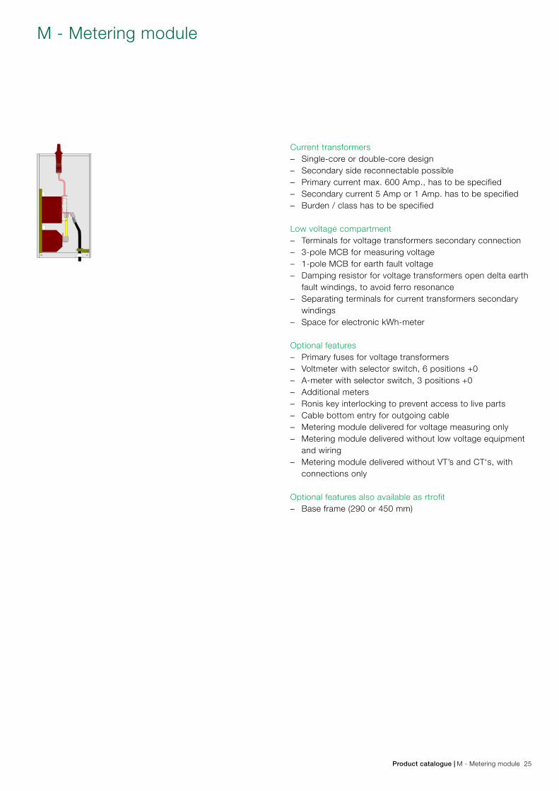
Current transformers – Single-core or double-core design – Secondary side reconnectable possible – Primary current max. 600 Amp., has to be specified – Secondary current 5 Amp or 1 Amp. has to be specified – Burden / class has to be specified
Low voltage compartment – Terminals for voltage transformers secondary connection – 3-pole MCB for measuring voltage – 1-pole MCB for earth fault voltage – Damping resistor for voltage transformers open delta earth
fault windings, to avoid ferro resonance – Separating terminals for current transformers secondary
windings – Space for electronic kWh-meter
Optional features – Primary fuses for voltage transformers – Voltmeter with selector switch, 6 positions +0 – A-meter with selector switch, 3 positions +0 – Additional meters – Ronis key interlocking to prevent access to live parts – Cable bottom entry for outgoing cable – Metering module delivered for voltage measuring only – Metering module delivered without low voltage equipment
and wiring – Metering module delivered without VT’s and CT‘s, with
connections only
Optional features also available as rtrofit – Base frame (290 or 450 mm)
M - Metering module
Product catalogue | M - Metering module 25
3
3
� �� SafePlus
3
3
� ��SafePlus
� �� SafePlus
� ��SafePlus
Technical dataMetering tariff moduleRated voltage kV 12 24Power frequency withstand voltage kV 28 50Impulse withstand voltage kV 95 125Rated normal current A 630 630Short time current 1 sec. kA 20 20
The Mt-module is a factory assembled type tested air insulat-ed non arc proof metering cubicle with conventional CTs and VTs. The Mt-module is designed for CTs and VTs with dimen-sions according to DIN 42600 Narrow type and for installation of transformers locally.
The Mt-module is manufactured and tested according to IEC 62271-200. It is available in 3 versions: – Bottom cable in/out (A) – Left side top connection for outgoing cable, bottom cable
in (B) – Right side top connection for outgoing cable, bottom cable
in (C)
Standard features – 3 pcs DIN 42600 Narrow type current transformers with
ribs – 3 pcs DIN Narrow type single pole voltage transformers – Padlock interlocking to prevent access to live parts – MV cable connection to SafePlus cubicle using Elastimold,
3M, Pirelli, Raychem, Kabeldon, etc. connectors – MV cable connection inside Mt-module by conventional
cable lugs
Voltage transformers – Single pole insulated with measuring and earth fault wind
ings – Primary voltage and frequency (50 or 60 Hz) has to be
specified – Secondary windings --/110:V3/110:3V or --/100:V3/100:3V
has to be specified – Note: VTs can also be delivered without open Delta Earth
fault windings – Burden / class has to be specified
Current transformers – Single-core or double-core design – Secondary side reconnectable possible – Primary current max 600 Amp, has to be specified – Secondary current 5 Amp or 1 Amp has to be specified
Mt - Metering tariff module
Depth: 1047 mmWidth: 800 mmHeight: 1806 mm
26 Mt - Metering tariff module | Product Catalogue
� ��SafePlus
17
1
2
34
10
11
5 6 7 8
9
18
12
13
14
16
15
Upper front cover1. Manometer2. Nameplate module3. Short circuit indicator4. Capacitive voltage indication5. Load break / earthing switch position indicator6. Push buttons close/open operation7. Charged spring indicator8. Self powered protection relay9. Vacuum circuit-breaker position
Lower front cover10. Nameplate switchgear11. Fuse blown indicator12. Disconnector / earthing switch position indicator13. Capacitive voltage indication Cable compartment cover14. Cable compartment cover standard15. Cable compartment cover with inspection window16. Support bar (removable) Side cover17. Lifting lug18. Operating handle (standard on right hand side)
CoversUpper and lower front cover have a thickness of 3 mm alu-minium which is covered with a polycarbonate foil. These foils contain the mimic diagram of the main circuit with the position indicators for the switching devices. Background colour for these foils is light grey (RAL 7035). The upper front cover is removable. The lower front cover can be opened.
There are four different cable compartment covers; standard, with inspection window, arc proof and with extra depth for parallel cables. These covers are manufactured from 1.25 mm aluzink (except the arc proof cover) and are powder painted with colour RAL 7035. All cable compartment covers are removable. Each module has a separate cable compartment which is divided from the others by means of partition walls. These partition walls can easily be removed, allowing a comfortable access for connec-tion of cables.A vertical partition wall is fitted to divide the cable compartment(s) from the rear side of the switchgear / ring main unit. In case of an arc fault inside the SF6 tank, followed by an opening of the pressure relief in the bottom of the tank, this partition wall will prevent the hot gases blowing out from the pressure relief to enter the cable compartments. Side covers are made of 2 millimeter hot rolled steel and pow-der painted with colour RAL 7035.
Outer assembly
Product catalogue | Outer assembly 27
The cable switch (C-Module) is a three positioning switch-disconnector and earthing switch using SF6 gas as an arc quenching medium.
The switch positioning is close – open – earthed. In the open position the switch satisfies the disconnector requirements.
C-module equipped with arc suppressor (optional equipment) and cable test bushings (optional equipment).
Cable switch module
28 Cable switch module | Product Catalogue
The vacuum circuit-breaker (V-Module) has vacuum bottles as interrupters of the current. In series with the circuit-breaker main circuit is connected a three-position disconnector/earthing switch. The operation between vacuum circuit breaker and discon-nector/earthing switch is mechanically interlocked.
Vacuum circuit-breaker module
Product catalogue | Vacuum circuit-breaker module 29
The switch-fuse (F-module) has a three positioning switch disconnector and earthing switch identical to the cable switch (C-module).
By means of the fuse tripping device it operates as a switch-fuse combination. There is a double earthing switch which in earthed position connects earth to both sides of the fuse-links simultaneously.
Both earthing switches are operated in one operation. The switch-fuse and earthing switch is mechanically interlocked to prevent hazardous access to the fuse-links.
The lower cover which gives access to the fuse-links is also mechanically interlocked with the earthing switch.
3-ways unit consisting of two C-modules and one F-module. Both C-modules are equipped with arc suppressor (optional equipment) and cable test bushings (optional equipment).
Switch-fuse module
30 Switch-fuse module | Product Catalogue
The connection of the HV-cables is made by cable bushings. The bushings are made of cast resin with moulded-in conduc-tors. In addition, a screen is moulded in to control the electri-cal field and is also used as the main capacitor supplying the voltage indicating systems.
ABB has produced bushings for SF6 switchgears since 1985. Up to date production facilities and highly advanced robots and test equipment ensure the high quality required for each single device. A very high number of units have been installed worldwide in distribution networks, power stations and industrial com-plexes.
Used together with full-screened connectors an ideal solution for areas with a history of humidity or condensation problems is achieved. The bushings are designed according to Cenelec EN 50181, EDF HN 52-S-61 and IEC 60137.
There are 5 different cable bushings: – Interface A (200 series with plug-in contact, In=200A) – Interface B (400 series with plug-in contact, In=400A) – Interface C (400 series with M16 bolted contact, In=630A) – Interface C (400 series with M16 bolted contact) and inte
grated voltage and current sensors (In=630A) – Interface D (600 series with M16 bolted contact, In=630A)
Cable bushings
Product catalogue | Cable bushings 31
The arc suppressor is an optimal quick-make short circuit de-vice with a mechanical pressure detector that can be installed with each incoming feeder inside the sealed SF6 tank of the SafeRing and SafePlus switchgear.
If an arc fault should occur inside the SF6 tank the pressure detector of the arc suppressor will automatically trip the short circuit device of the incoming feeder(s) within milliseconds, thereby transforming the arc fault into a bolted fault. The arc is extinguished without any emission of hot gases and the bolted short circuit will be interrupted by the upstream circuit-breaker.
No links or release mechanisms are installed outside the tank. Corrosion and any environmental influences are therefore prevented, giving optimum reliability.
The pressure detector is insensitive to pressure changes due to variation in atmospheric temperature or pressure as well as external phenomena such as vibrations or shocks.
The arc suppressor will operate for short-circuit currents in the range of 1kArms to 21kArms and it will reduce the gener-ated arc energy to less than 5% of the arc energy released during an arcing time of 1 sec.
A signalling device (1NO) will indicate local or remote the trip-ping of one or more arc suppressors.
Since the system is self-contained, an internal arc fault will have no impact on the surroundings. No arc fault tests have to be repeated in combination with channel release systems or transformer stations. The costs of the cleaning work which has to be done after an internal arc fault when the release flap has opened, are reduced to zero.
Arc suppressor
32 Arc suppressor | Product Catalogue
SafeRing and SafePlus use SF6 –gas (Sulphur hexafluoride) as insulation and quenching medium. The SF6 is contained in a welded stainless steel tank, which is hermetically sealed. The pressure system is defined as a sealed for life system with an operating life time exceeding 30 years. The leakage rate is less than 0,1% per year.
In order to guarantee a reliable and tight welding, all welding work is carried out by computer controlled robots. Electrical and mechanical bushings penetrating the tank are clamped and sealed to the tank by high quality O-rings.
The mechanical bushing has in addition a rotating shaft which connects the shaft of the switch to the corresponding shaft of the mechanism. The rotating shaft is sealed by a double set of gas seals.
All SF6-tanks have to pass a leakage test, before gas fill-ing. Leakage test and gas filling are done inside a vacuum chamber. The first step in the leakage test is to evacuate all air inside both SF6-tank and vacuum chamber simultaneously. Then the SF6-tank is filled with Helium. Due to the charac-teristics of Helium this test will detect absolutely all possible leakages. If the SF6-tank passes this test, the Helium will be evacuated and replaced by SF6.
The SF6-tank has a degree of protection of IP67, and can be immersed into water and still maintain all functions in a satis-factory way.
Completely sealed system
Product catalogue | Completely sealed system 33
As an option, both C- and De-modules can be equipped with cable test bushings situated behind the lower front cover. This cover can be interlocked against the earthing switch to avoid access to the cable test compartment before earthing switch is in closed position.
When these bushings are mounted, cable insulation test can easily be done according to the following procedure:
Principle sketch for testing:1. Close the earthing switch after having checked the voltage indicators2. Open compartment cover3. Install the injection device onto the access terminals4. Open the removable earthing bridge5. Perform cable testing6. Re-install the earthing bridge7. Remove the injection device8. Close compartment cover9. Open the earthing switch
If the switchgear is not equipped with cable test bushings, cable testing is possible directly at the cable connectors if they are designed for this purpose, please follow the sup-plier’s instruction.
Cable test bushings
34 Cable test bushings | Product Catalogue
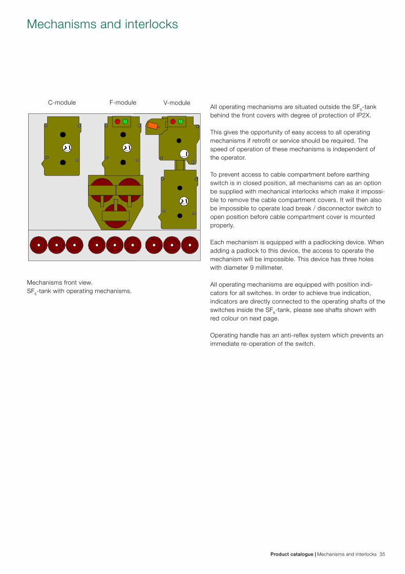
All operating mechanisms are situated outside the SF6-tank behind the front covers with degree of protection of IP2X.
This gives the opportunity of easy access to all operating mechanisms if retrofit or service should be required. The speed of operation of these mechanisms is independent of the operator.
To prevent access to cable compartment before earthing switch is in closed position, all mechanisms can as an option be supplied with mechanical interlocks which make it impossi-ble to remove the cable compartment covers. It will then also be impossible to operate load break / disconnector switch to open position before cable compartment cover is mounted properly.
Each mechanism is equipped with a padlocking device. When adding a padlock to this device, the access to operate the mechanism will be impossible. This device has three holes with diameter 9 millimeter.
All operating mechanisms are equipped with position indi-cators for all switches. In order to achieve true indication, indicators are directly connected to the operating shafts of the switches inside the SF6-tank, please see shafts shown with red colour on next page.
Operating handle has an anti-reflex system which prevents an immediate re-operation of the switch.
C-module F-module V-module
Mechanisms front view.SF6-tank with operating mechanisms.
Mechanisms and interlocks
Product catalogue | Mechanisms and interlocks 35
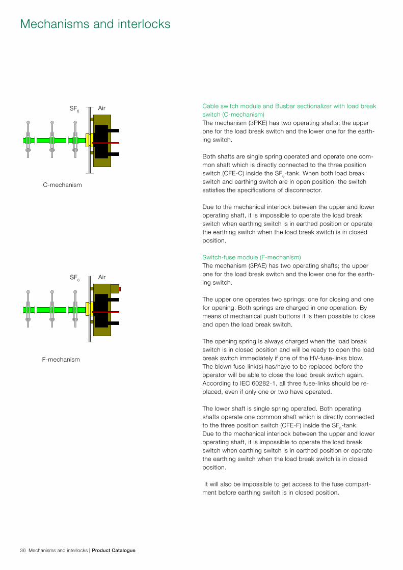
Cable switch module and Busbar sectionalizer with load break switch (C-mechanism)The mechanism (3PKE) has two operating shafts; the upper one for the load break switch and the lower one for the earth-ing switch.
Both shafts are single spring operated and operate one com-mon shaft which is directly connected to the three position switch (CFE-C) inside the SF6-tank. When both load break switch and earthing switch are in open position, the switch satisfies the specifications of disconnector.
Due to the mechanical interlock between the upper and lower operating shaft, it is impossible to operate the load break switch when earthing switch is in earthed position or operate the earthing switch when the load break switch is in closed position.
Switch-fuse module (F-mechanism)The mechanism (3PAE) has two operating shafts; the upper one for the load break switch and the lower one for the earth-ing switch.
The upper one operates two springs; one for closing and one for opening. Both springs are charged in one operation. By means of mechanical push buttons it is then possible to close and open the load break switch.
The opening spring is always charged when the load break switch is in closed position and will be ready to open the load break switch immediately if one of the HV-fuse-links blow. The blown fuse-link(s) has/have to be replaced before the operator will be able to close the load break switch again. According to IEC 60282-1, all three fuse-links should be re-placed, even if only one or two have operated.
The lower shaft is single spring operated. Both operating shafts operate one common shaft which is directly connected to the three position switch (CFE-F) inside the SF6-tank. Due to the mechanical interlock between the upper and lower operating shaft, it is impossible to operate the load break switch when earthing switch is in earthed position or operate the earthing switch when the load break switch is in closed position.
It will also be impossible to get access to the fuse compart-ment before earthing switch is in closed position.
C-mechanism
F-mechanism
SF6
SF6
Air
Air
Mechanisms and interlocks
36 Mechanisms and interlocks | Product Catalogue
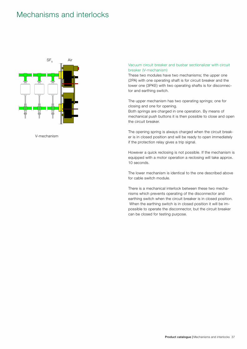
Vacuum circuit breaker and busbar sectionalizer with circuit breaker (V-mechanism)These two modules have two mechanisms; the upper one (2PA) with one operating shaft is for circuit breaker and the lower one (3PKE) with two operating shafts is for disconnec-tor and earthing switch.
The upper mechanism has two operating springs; one for closing and one for opening. Both springs are charged in one operation. By means of mechanical push buttons it is then possible to close and open the circuit breaker.
The opening spring is always charged when the circuit break-er is in closed position and will be ready to open immediately if the protection relay gives a trip signal.
However a quick reclosing is not possible. If the mechanism is equipped with a motor operation a reclosing will take approx. 10 seconds.
The lower mechanism is identical to the one described above for cable switch module.
There is a mechanical interlock between these two mecha-nisms which prevents operating of the disconnector and earthing switch when the circuit breaker is in closed position. When the earthing switch is in closed position it will be im-possible to operate the disconnector, but the circuit breaker can be closed for testing purpose.
V-mechanism
SF6 Air
Mechanisms and interlocks
Product catalogue | Mechanisms and interlocks 37
� ��SafePlus
��SafePlus
��SafeRing
SafePlus �� �� �� SafePlus �� SafePlus ��SafePlusSafePlus
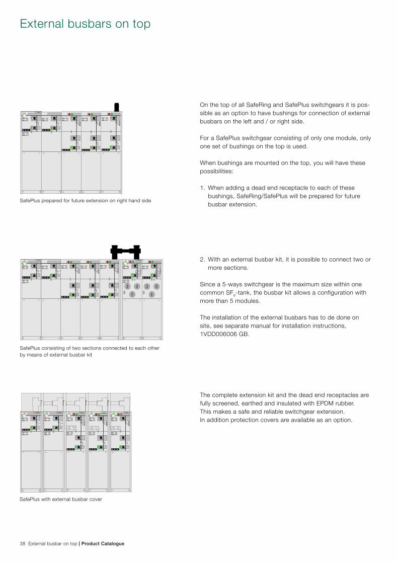
On the top of all SafeRing and SafePlus switchgears it is pos-sible as an option to have bushings for connection of external busbars on the left and / or right side.
For a SafePlus switchgear consisting of only one module, only one set of bushings on the top is used.
When bushings are mounted on the top, you will have these possibilities:
1. When adding a dead end receptacle to each of these bushings, SafeRing/SafePlus will be prepared for future busbar extension.
2. With an external busbar kit, it is possible to connect two or more sections. Since a 5-ways switchgear is the maximum size within one common SF6-tank, the busbar kit allows a configuration with more than 5 modules.
The installation of the external busbars has to de done on site, see separate manual for installation instructions, 1VDD006006 GB.
The complete extension kit and the dead end receptacles are fully screened, earthed and insulated with EPDM rubber. This makes a safe and reliable switchgear extension.In addition protection covers are available as an option.
External busbars on top
SafePlus consisting of two sections connected to each other by means of external busbar kit
SafePlus prepared for future extension on right hand side
SafePlus with external busbar cover
38 External busbar on top | Product Catalogue
SafePlus� ��� �� � �� SafePlus� �� SafePlus� ��SafePlusSafePlus
� ��SafePlus
� ��SafePlus
� ��SafePlus
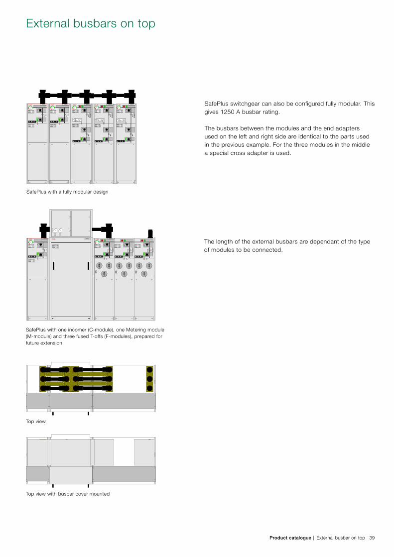
SafePlus switchgear can also be configured fully modular. This gives 1250 A busbar rating.
The busbars between the modules and the end adapters used on the left and right side are identical to the parts used in the previous example. For the three modules in the middle a special cross adapter is used.
The length of the external busbars are dependant of the type of modules to be connected.
External busbars on top
SafePlus with a fully modular design
Top view
Top view with busbar cover mounted
SafePlus with one incomer (C-module), one Metering module (M-module) and three fused T-offs (F-modules), prepared for future extension
Product catalogue | External busbar on top 39
� ��SafeRing
� ��SafePlus
� ��SafePlus
� ��SafePlus� ��
SafePlus� ��
SafePlus
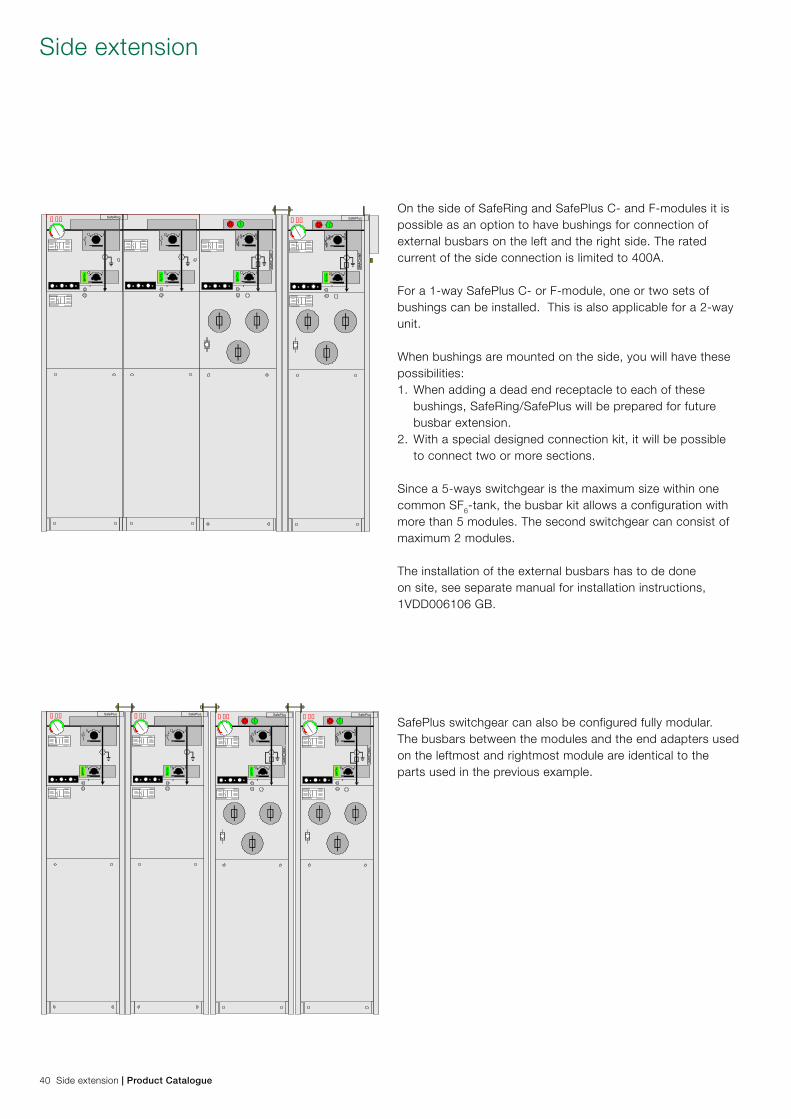
On the side of SafeRing and SafePlus C- and F-modules it is possible as an option to have bushings for connection of external busbars on the left and the right side. The rated current of the side connection is limited to 400A.
For a 1-way SafePlus C- or F-module, one or two sets of bushings can be installed. This is also applicable for a 2-way unit.
When bushings are mounted on the side, you will have these possibilities:1. When adding a dead end receptacle to each of these bushings, SafeRing/SafePlus will be prepared for future busbar extension.2. With a special designed connection kit, it will be possible to connect two or more sections. Since a 5-ways switchgear is the maximum size within one common SF6-tank, the busbar kit allows a configuration with more than 5 modules. The second switchgear can consist of maximum 2 modules.
The installation of the external busbars has to de done on site, see separate manual for installation instructions, 1VDD006106 GB.
SafePlus switchgear can also be configured fully modular. The busbars between the modules and the end adapters used on the leftmost and rightmost module are identical to the parts used in the previous example.
Side extension
40 Side extension | Product Catalogue
SafePlus� ��
REF 610� ��
SafePlus� ��
REF 610� ��
SafePlus� ��
REF 610� ��
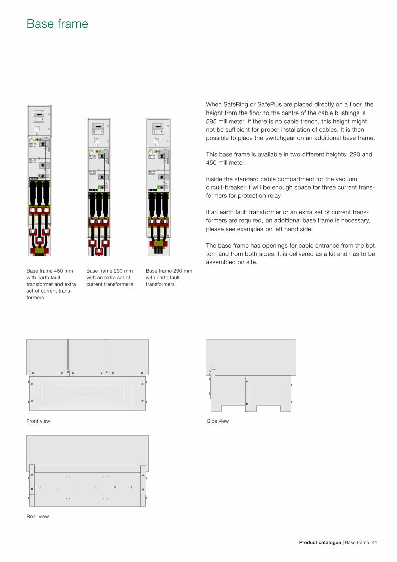
When SafeRing or SafePlus are placed directly on a floor, the height from the floor to the centre of the cable bushings is 595 millimeter. If there is no cable trench, this height might not be sufficient for proper installation of cables. It is then possible to place the switchgear on an additional base frame.
This base frame is available in two different heights; 290 and 450 millimeter.
Inside the standard cable compartment for the vacuum circuit-breaker it will be enough space for three current trans-formers for protection relay.
If an earth fault transformer or an extra set of current trans-formers are required, an additional base frame is necessary, please see examples on left hand side.
The base frame has openings for cable entrance from the bot-tom and from both sides. It is delivered as a kit and has to be assembled on site.
Base frame 450 mmwith earth fault transformer and extra set of current trans-formers
Base frame 290 mmwith an extra set of current transformers
Base frame 290 mmwith earth faulttransformers
Base frame
Front view
Rear view
Side view
Product catalogue | Base frame 41
� ��SafeRing
SafePlus� ��
� �� REF541
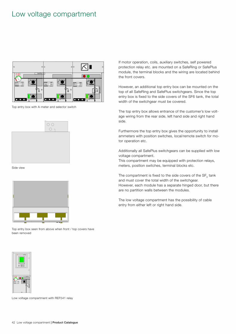
If motor operation, coils, auxiliary switches, self powered protection relay etc. are mounted on a SafeRing or SafePlus module, the terminal blocks and the wiring are located behind the front covers.
However, an additional top entry box can be mounted on the top of all SafeRing and SafePlus switchgears. Since the top entry box is fixed to the side covers of the SF6 tank, the total width of the switchgear must be covered.
The top entry box allows entrance of the customer’s low volt-age wiring from the rear side, left hand side and right hand side.
Furthermore the top entry box gives the opportunity to install ammeters with position switches, local/remote switch for mo-tor operation etc.
Additionally all SafePlus switchgears can be supplied with low voltage compartment. This compartment may be equipped with protection relays, meters, position switches, terminal blocks etc.
The compartment is fixed to the side covers of the SF6 tank and must cover the total width of the switchgear. However, each module has a separate hinged door, but there are no partition walls between the modules.
The low voltage compartment has the possibility of cable entry from either left or right hand side.
Low voltage compartment
Top entry box with A-meter and selector switch
Top entry box seen from above when front / top covers have been removed
Low voltage compartment with REF541 relay
Side view
42 Low voltage compartment | Product Catalogue
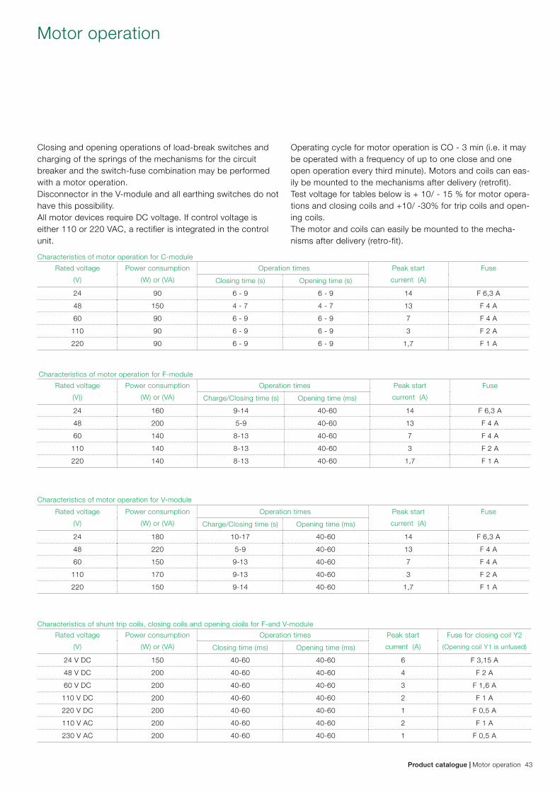
Closing and opening operations of load-break switches and charging of the springs of the mechanisms for the circuit breaker and the switch-fuse combination may be performed with a motor operation. Disconnector in the V-module and all earthing switches do not have this possibility.All motor devices require DC voltage. If control voltage is either 110 or 220 VAC, a rectifier is integrated in the control unit.
Operating cycle for motor operation is CO - 3 min (i.e. it may be operated with a frequency of up to one close and one open operation every third minute). Motors and coils can eas-ily be mounted to the mechanisms after delivery (retrofit). Test voltage for tables below is + 10/ - 15 % for motor opera-tions and closing coils and +10/ -30% for trip coils and open-ing coils.The motor and coils can easily be mounted to the mecha-nisms after delivery (retro-fit).
Motor operation
Characteristics of motor operation for C-module
Characteristics of motor operation for F-module
Characteristics of motor operation for V-module
Characteristics of shunt trip coils, closing coils and opening cioils for F-and V-module
Product catalogue | Motor operation 43
Rated voltage
(V)
Power consumption
(W) or (VA)
Operation times Peak start
current (A)
Fuse
Closing time (s) Opening time (s)
24 90 6 - 9 6 - 9 14 F 6,3 A
48 150 4 - 7 4 - 7 13 F 4 A
60 90 6 - 9 6 - 9 7 F 4 A
110 90 6 - 9 6 - 9 3 F 2 A
220 90 6 - 9 6 - 9 1,7 F 1 A
Rated voltage
(V))
Power consumption
(W) or (VA)
Operation times Peak start
current (A)
Fuse
Charge/Closing time (s) Opening time (ms)
24 160 9-14 40-60 14 F 6,3 A
48 200 5-9 40-60 13 F 4 A
60 140 8-13 40-60 7 F 4 A
110 140 8-13 40-60 3 F 2 A
220 140 8-13 40-60 1,7 F 1 A
Rated voltage
(V)
Power consumption
(W) or (VA)
Operation times Peak start
current (A)
Fuse
Charge/Closing time (s) Opening time (ms)
24 180 10-17 40-60 14 F 6,3 A
48 220 5-9 40-60 13 F 4 A
60 150 9-13 40-60 7 F 4 A
110 170 9-13 40-60 3 F 2 A
220 150 9-14 40-60 1,7 F 1 A
Rated voltage
(V)
Power consumption
(W) or (VA)
Operation times Peak start
current (A)
Fuse for closing coil Y2
(Opening coil Y1 is unfused)Closing time (ms) Opening time (ms)
24 V DC 150 40-60 40-60 6 F 3,15 A
48 V DC 200 40-60 40-60 4 F 2 A
60 V DC 200 40-60 40-60 3 F 1,6 A
110 V DC 200 40-60 40-60 2 F 1 A
220 V DC 200 40-60 40-60 1 F 0,5 A
110 V AC 200 40-60 40-60 2 F 1 A
230 V AC 200 40-60 40-60 1 F 0,5 A
1
2
2
6
3
3
1 4 5
5
7
1
3
8 9 4 12
13
10
11
14
15
16
1718
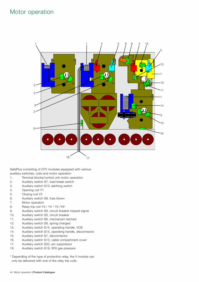
SafePlus consisting of CFV modules equipped with various auxiliary switches, coils and motor operation1. Terminal blocks/control unit motor operation 2. Auxiliary switch S7, load break switch3. Auxiliary switch S10, earthing switch4. Opening coil Y15. Closing coil Y26. Auxiliary switch S9, fuse blown7. Motor operation8. Relay trip coil Y3 / Y4 / Y5 /Y6*9. Auxiliary switch S9, circuit breaker tripped signal10. Auxiliary switch S5, circuit breaker11. Auxiliary switch S6, mechanism latched12. Auxiliary switch S8, spring charged13. Auxiliary switch S14, operating handle, VCB14. Auxiliary switch S15, operating handle, disconnector15. Auxiliary switch S7, disconnector16. Auxiliary switch S13, cable compartment cover17. Auxiliary switch S20, arc suppressor18. Auxiliary switch S19, SF6 gas pressure
* Depending of the type of protection relay, the V module can only be delivered with one of the relay trip coils.
Motor operation
44 Motor operation | Product Catalogue
� ��SafeRing
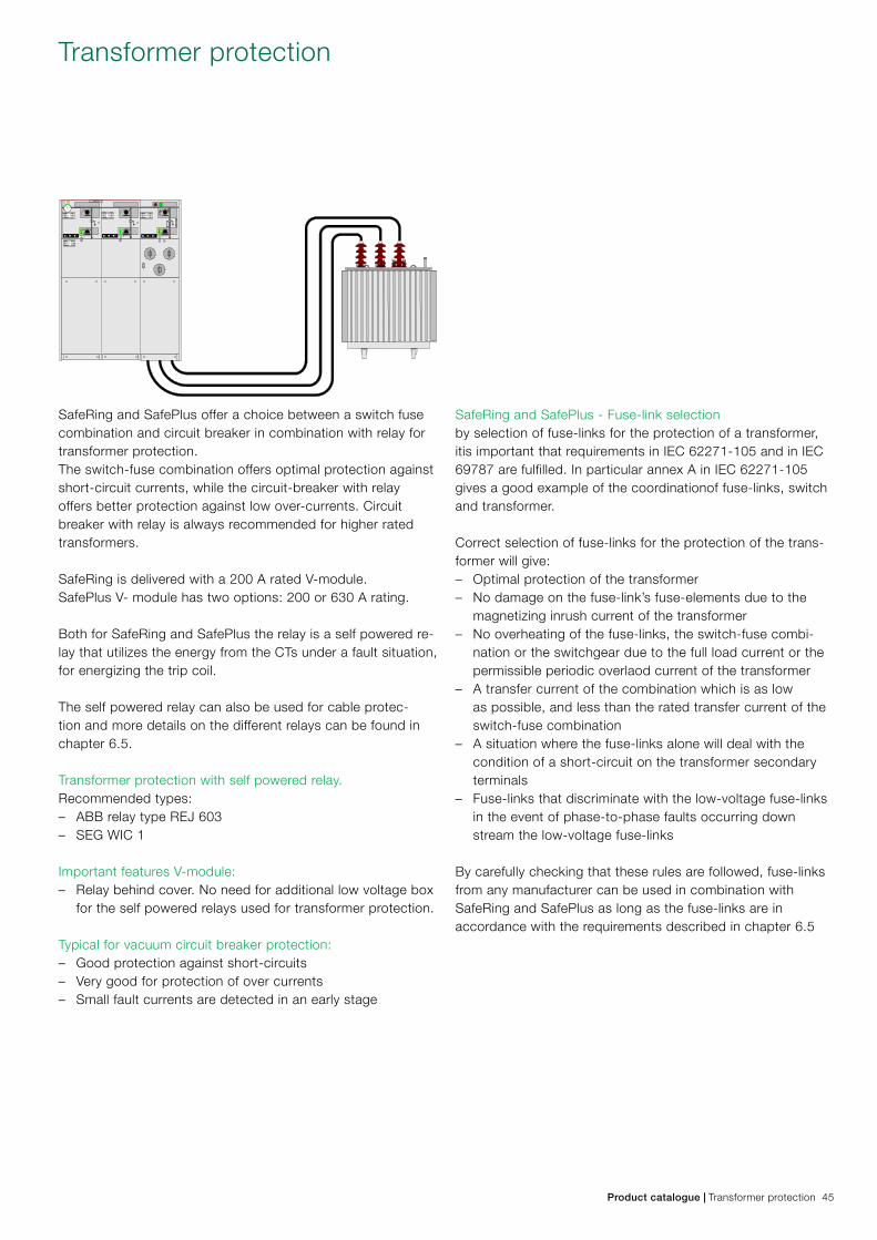
SafeRing and SafePlus offer a choice between a switch fuse combination and circuit breaker in combination with relay for transformer protection. The switch-fuse combination offers optimal protection against short-circuit currents, while the circuit-breaker with relay offers better protection against low over-currents. Circuit breaker with relay is always recommended for higher rated transformers.
SafeRing is delivered with a 200 A rated V-module. SafePlus V- module has two options: 200 or 630 A rating. Both for SafeRing and SafePlus the relay is a self powered re-lay that utilizes the energy from the CTs under a fault situation, for energizing the trip coil. The self powered relay can also be used for cable protec-tion and more details on the different relays can be found in chapter 6.5.
Transformer protection with self powered relay.Recommended types: – ABB relay type REJ 603 – SEG WIC 1
Important features V-module: – Relay behind cover. No need for additional low voltage box
for the self powered relays used for transformer protection.
Typical for vacuum circuit breaker protection: – Good protection against short-circuits – Very good for protection of over currents – Small fault currents are detected in an early stage
SafeRing and SafePlus - Fuse-link selectionby selection of fuse-links for the protection of a transformer, itis important that requirements in IEC 62271-105 and in IEC 69787 are fulfilled. In particular annex A in IEC 62271-105 gives a good example of the coordinationof fuse-links, switch and transformer.
Correct selection of fuse-links for the protection of the trans-former will give: – Optimal protection of the transformer – No damage on the fuse-link’s fuse-elements due to the
magnetizing inrush current of the transformer – No overheating of the fuse-links, the switch-fuse combi-
nation or the switchgear due to the full load current or the permissible periodic overlaod current of the transformer – A transfer current of the combination which is as low
as possible, and less than the rated transfer current of the switch-fuse combination – A situation where the fuse-links alone will deal with the
condition of a short-circuit on the transformer secondary terminals – Fuse-links that discriminate with the low-voltage fuse-links
in the event of phase-to-phase faults occurring down stream the low-voltage fuse-links
By carefully checking that these rules are followed, fuse-links from any manufacturer can be used in combination with SafeRing and SafePlus as long as the fuse-links are in accordance with the requirements described in chapter 6.5
Transformer protection
Product catalogue | Transformer protection 45
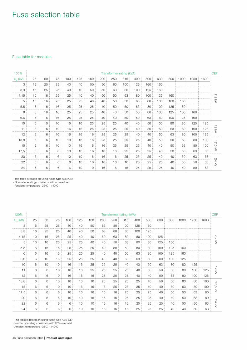
100% Transformer rating (kVA) CEF
Un (kV) 25 50 75 100 125 160 200 250 315 400 500 630 800 1000 1250 1600
7,2 kV
3 16 25 25 40 40 50 50 80 100 125 160 160
3,3 16 25 25 40 40 50 50 63 80 100 125 160
4,15 10 16 25 25 40 40 50 50 63 80 100 125 160
5 10 16 25 25 25 40 40 50 50 63 80 100 160 160
5,5 6 16 16 25 25 25 40 50 50 63 80 100 125 160
6 6 16 16 25 25 25 40 40 50 50 80 100 125 160 160
6,6 6 16 16 25 25 25 40 40 50 50 63 80 100 125 160
10 6 10 10 16 16 25 25 25 40 40 50 50 80 80 125 125 12 kV11 6 6 10 16 16 25 25 25 25 40 50 50 63 80 100 125
12 6 6 10 16 16 16 25 25 25 40 40 50 63 80 100 125
13,8 6 6 10 10 16 16 25 25 25 25 40 50 50 63 80 100 17,5 kV
15 6 6 10 10 16 16 16 25 25 25 40 40 50 63 80 100
17,5 6 6 6 10 10 16 16 16 25 25 25 40 50 50 63 80
20 6 6 6 10 10 16 16 16 25 25 25 40 40 50 63 63 24 kV22 6 6 6 6 10 10 16 16 16 25 25 25 40 50 50 63
24 6 6 6 6 10 10 16 16 16 25 25 25 40 40 50 63
Fuse table for modules
- The table is based on using fuses type ABB CEF- Normal operating consitions with no overload- Ambient temperature -25oC - +40oC
120% Transformer rating (kVA) CEF
Un (kV) 25 50 75 100 125 160 200 250 315 400 500 630 800 1000 1250 1600
7,2 kV
3 16 25 25 40 40 50 63 80 100 125 160
3,3 16 25 25 40 40 50 63 80 80 100 125
4,15 10 16 25 25 40 40 50 63 80 80 100 125
5 10 16 25 25 25 40 40 50 63 80 80 125 160
5,5 6 16 16 25 25 25 40 50 50 80 80 100 125 160
6 6 16 16 25 25 25 40 40 50 63 80 100 125 160
6,6 6 16 16 25 25 25 40 40 50 63 80 80 100 125
10 6 10 10 16 16 25 25 25 40 40 50 63 80 80 125 12 kV11 6 6 10 16 16 25 25 25 25 40 50 50 80 80 100 125
12 6 6 10 16 16 16 25 25 25 40 40 50 63 80 100 125
13,8 6 6 10 10 16 16 25 25 25 25 40 50 50 80 80 100 17,5 kV
15 6 6 10 10 16 16 16 25 25 25 40 40 50 63 80 100
17,5 6 6 6 10 10 16 16 16 25 25 25 40 50 50 63 80
20 6 6 6 10 10 16 16 16 25 25 25 40 40 50 63 80 24 kV22 6 6 6 6 10 10 16 16 16 25 25 25 40 50 50 63
24 6 6 6 6 10 10 16 16 16 25 25 25 40 40 50 63
- The table is based on using fuses type ABB CEF- Normal operating consitions with 20% overload- Ambient temperature -25oC - +40oC
Fuse selection table
46 Fuse selection table | Product Catalogue
SafeRing and SafePlus are designed and tested for fuse-links according to IEC 60282-1
The dimensions of the fuse-links have to be in accordance with IEC 60282-1, Annex D. The fuse-links have to be type I with terminal diameter equal to 45 +1 mm and body length (e) equal to 442 mm.
The dimensions of the fuse-links can also to be in accordance with DIN 43625 and the length of the fuse canister is based on the use of fuse-links with length 442 mm. For installation of shorter fuses, (<24kV ) a fuse adapter will be needed.Please note: When inserting the fuse-link into the canister, the striker-pin must always face outwards against the fuse holder. Fuse adapter has to be fixed to the fuse-link contact partwhich faces inwards in the fuse canister. 1600 kVA is the maximum size of distribution transformer which can be fed from a SafeRing / SafePlus switch-fuse module. For higher rated transformers, we recommend our vacuum circuit breaker module with CT’s and protection relay.
The below table shows CEF fuse-links for use in SafeRing/SafePlus. For more technical data, we refer to our ABB Po-land catalogue .In order to find the correct fuse-link compared to the trans-former rating in kVA, please see the selection table on previ-ous page.
Type Rated voltage kV Rated current A e / D mm Type Rated voltage kV Rated current A e / D mm
CEF 3,6/7,2 6 192/65 CEF 17,5 6 292/65
CEF 3,6/7,2 10 192/65 CEF 17,5 10 292/65
CEF 3,6/7,2 16 192/65 CEF 17,5 16 292/65
CEF 3,6/7,2 25 192/65 CEF 17,5 25 292/65
CEF 3,6/7,2 40 192/65 CEF 17,5 40 292/87
CEF 3,6/7,2 50 192/65 CEF 17,5 50 292/87
CEF 3,6/7,2 63 192/65 CEF 17,5 63 292/87
CEF 3,6/7,2 80 192/87 CEF 17,5 80 442/87
CEF 3,6/7,2 100 192/87 CEF 17,5 100 442/87
CEF 3,6/7,2 125 292/87
CEF 3,6/7,2 160 292/87
CEF 12 6 292/65 CEF 24 6 442/65
CEF 12 10 292/65 CEF 24 10 442/65
CEF 12 16 292/65 CEF 24 16 442/65
CEF 12 25 292/65 CEF 24 25 442/65
CEF 12 40 292/65 CEF 24 40 442/65
CEF 12 50 292/65 CEF 24 50 442/87
CEF 12 63 292/65 CEF 24 63 442/87
CEF 12 80 292/87
CEF 12 100 292/87
CEF 12 125 442/87
Fuse-links
Fuse holder Fuse adapterFuse-link
Product catalogue | Fuse-links 47
SafePlus can be delivered with a V-module with 630A vacuum circuit-breaker. This chapter describes the different choices of protection relays and feeder terminals that can be used in SafePlus. These relays require an additional low voltage compartment.
For transformer protection with max. 200A vacuum circuit breaker see chapter 6.4.
Standard test procedure is functional test of trip circuit of the relays. All customer settings must be done on site.
REF type feeder terminals are configured according to cus-tomer specification for protection functions. Special control requirements on request only.
The V-module can also be delivered prepared for protection relays.
This is defined in two types: – Trip coil and auxiliary contact. – Cut out in LV-compartment, trip coil, aux contact, wiring
and drawings.
This is applicable for relays delivered complete from our fac-tory or if we have received necessary documentation on the relay.
Other types of relays on request.
There are three main groups of relays delivered: A. ABB feeder protection relaysB. Self powered relaysC. ABB feeder terminals type REF 54x
A. ABB offers a wide range of feeder protection relays. These relays have been sold for a long period and have an excellent reputation for reliability and secure operation. These relays have either 18-80VDC or 80-265VAC/DC auxiliary supplies and are connected to conventional CTs and VTs.B. Self powered relays are suitable for rough conditions and places without possibility of auxiliary supply. SafeRing and SafePlus can be delivered with different types to fulfil all relevant needs in a distribution network. C. ABB feeder terminals, type REF 54x provides cost-effective solutions for different protection, monitoring and control applications.
The terminals enable the use of accurate and reliable current and voltage sensors as well as conventional CTs and VTs.
Relays
48 Relays | Product Catalogue
Protection and measurement Relay
Type of faults IEEE
device no.
IEC symbol Protection function REX1)
521
REF
610
REF
615
Short circuits 51 3 I > Non-directional overcurrent, low-set stage X X X
Short circuits 50/51/51B 3 I >> Non-directional overcurrent, high-set stage X X X
Short circuits 50/51B 3 I >>> Non-directional overcurrent instantaneous stage/blockable X X X
Short circuits 51 2 I > Two-phase non-directional overcurrent, low-set stage
Short circuits 50/51 2 I >> Two-phase non-directional overcurrent, high-set stage
Earth fault 51N Io > Non-directional earth fault, low-set stage X X X
Earth fault 51N Io >/SEF Non-directional earth fault, low-set stage sensitive
Earth fault 50N/51N Io >>/Io-o> Non-directional earth fault, high-set stage X X X
Earth fault 67N Io >-->/SEF Directional earth fault, sensitive, In=1A and 5A X X
Earth fault 67N Io >-->/SEF Directional earth fault, sensitive, In=0,2A and 1A
Earth fault 67N Io >> --> Directional earth fault, high-set stage X X
Earth fault 59N Uo > Residual overvoltage X X
Additional functions 46 ∆ I > Phase discontinuity X X
Additional functions 62BF CBFP Circuit-breaker failure X X X
Type of measurements current 31/21 Three-phase / two-phase current X X X
Type of measurements current Io Neutral current X X X
Type of measurements current ∆ I Degree of unbalance
Type of measurements current Uo Residual voltage X X
Auto-reclosing 79 X X X
ABB feeder protection relays
Self-powered relays
Functionality Relay
FeaturesDescription IEEE
device no.REJ 603 WIC 1
Protection functions Phase overdurrent (multi-characteristic) 50/51 X X
Protection functions Short-curcuit protection 50/51 X X
Protection functions Number of overcurrent elements 50/51B 2 2
Protection functions Earth fault current 50N/51N X X
Protection functions Number of earth fault elements 2 1
Characteristic curves Overcurrent element DEFT,INV 1) DEFT,INV 1)
Characteristic curves Earth fault current DEFT,INV 1) DEFT
Additional functions Trip indication X X (option)
Additional functions Electro-impulse X X
Additional functions input remote tripping (voltage) X 115VAC/230VAC
Additional functions Auxiliary power, voltage (option)
Measuring circuit Rated secondary currentwide range
special CT
wide range
special CT
Measuring circuit Measuring range, start current I> (A) 7,2 14,4
Climatic withstand Storage temperature (°C) -40 …+85 -40 …+85
Climatic withstand Operating temperature (°C) -40 …+85 -40 …+85
1) - Definite time overcurrent (DEFT) - Normal inverse time overcurrent (NINV) - Very inverse time overcurrent (VINV) - Extremely inverse time overcurrent (EINV) - Long time inverse time overcurrent (LINV)
- Resistance inverse timeovercurrent (RINV)- Characteristics of high voltage fuse-link (HV-FUSE)- Characteristics of full range fuse (FR-FUSE)- Definite time overcurrent - Inverse characteristics, please contact us for further information
1)Available protection functions dependant of version
Relays
Product catalogue | Relays 49
SEC WIC1 transformer protection and cable
protection kit (self powered)
Ring core current transformer type Current range
Transformer type W2 16 - 56 A
Transformer type W3 32 - 112 A
Transformer type W4 64 - 224 A
Transformer type W5 128 - 448 A
REJ603 transformer protection and cable
protection kit (self powered)
Ring core current transformer type Current range
Transformer type CT1 8 - 28 A
Transformer type CT2 16 - 56 A
Transformer type CT3 32 - 112 A
Transformer type CT4 64 - 224 A
Transformer type CT5 128 - 448 A
Protection relay standard CT’s typical Ring core current transformer type Ration - burden
Transformer type: class 10P10 SVA 100-100-45 50-100-200/1 A 1,5/3/6 VA
Transformer type: class 5P10 SVA 100-100-45 150/1 A 4 VA
Transformer type: class 5P10 SVA 100-100-45 100-200/1 A 4 - 7 VA
Transformer type: class 5P10 SVA 100-100-45 300-600/1 A 4 - 7 VA
Transformer type: class 5P10 SVA 100-100-45 400-600/1 A 4 - 7 VA
Earth fault transformer
Earth fault transformer, class 10P10, burden
0,5 - 15VA dependent on selected ratio KOLMA 06A1 (90 mm)
Multi-tap secondary:
50-150/1 A or 50-750/5 A
Earth fault transformer, class 10P10, burden
0,5 - 15VA dependent on selected ratio KOLMA 06D1 (180 mm)
Multi-tap secondary:
50-150/1 A or 50-750/5
Relays
Ring core current transformers and earth fault transformers
50 Relays | Product Catalogue

ABB feeder terminals SafePlus can be delivered with two different REF series feeder terminals. – REF 541 which is installed in the door of the low voltage
compartment. – REF542plus with integrated web-interface is a leader in
the development of feeder terminals. REF 542plus has a separate display unit and does not need a build out frame. – REF630, part of the Relion® product family designed to
implement the core values of the IEC61850 standards. The units are configured according to customer specification for protection functions.
Typical configuration of V-module:Primary equipment, standard – 630A vacuum circuit breaker – Disconnector – Earthing switch
Additional equipment – Trip coil(Y4) – HR voltage indication – Combisensors with 400series interface – Low voltage compartment – REF 542plus or REF 541 – Motor operation – Earth fault transformer (sensitive earth fault)
REF630REF630 is a comprehensive feeder management IED for protection, control, measuring and supervision of utility and industrial distribution substations. REF630 is a member of ABB’s Relion® product family and a part its 630 product series characterized by functional scalability and flexible con-figurability. REF630 also features necessary control functions constituting an ideal solution for feeder bay control. REF630 provides main protection for overhead lines and cable feeders of distribution networks. REF630 fits both isolated neutral networks and networks with resistance or impedance earthed neutral. Four pre-defined configurations to match typ-ical feeder protection and control requirements are available. The pre-defined configurations can be used as such or easily adapted or extended with freely selectable add-on functions, by means of which the IED can be fine-tuned to exactly satisfy the specific requirements of your present application.REF630 incorporates local and remote control functions. The IED offers a number of freely assignable binary inputs/outputs and logic circuits for establishing bay control and interlocking functions for circuit breakers and motor operated switch-dis-connectors. REF630 supports both single and double busbar substation busbar layouts.
Relays
Product catalogue | Relays 51
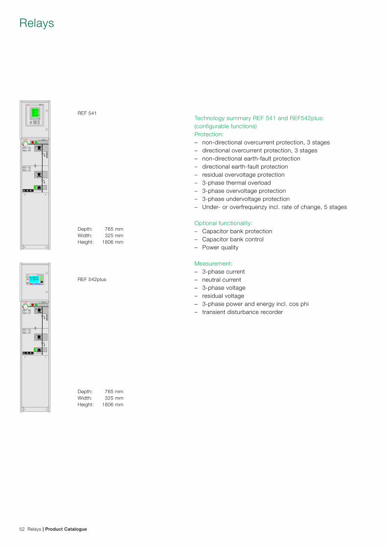
SafePlus� ��
� �� REF541
SafePlus� ��
� �� REF542plus
Menu
Technology summary REF 541 and REF542plus:(configurable functions)Protection: – non-directional overcurrent protection, 3 stages – directional overcurrent protection, 3 stages – non-directional earth-fault protection – directional earth-fault protection – residual overvoltage protection – 3-phase thermal overload – 3-phase overvoltage protection – 3-phase undervoltage protection – Under- or overfrequenzy incl. rate of change, 5 stages
Optional functionality: – Capacitor bank protection – Capacitor bank control – Power quality
Measurement: – 3-phase current – neutral current – 3-phase voltage – residual voltage – 3-phase power and energy incl. cos phi – transient disturbance recorder
Depth: 765 mmWidth: 325 mmHeight: 1806 mm
REF 541
Depth: 765 mmWidth: 325 mmHeight: 1806 mm
REF 542plus
Relays
52 Relays | Product Catalogue
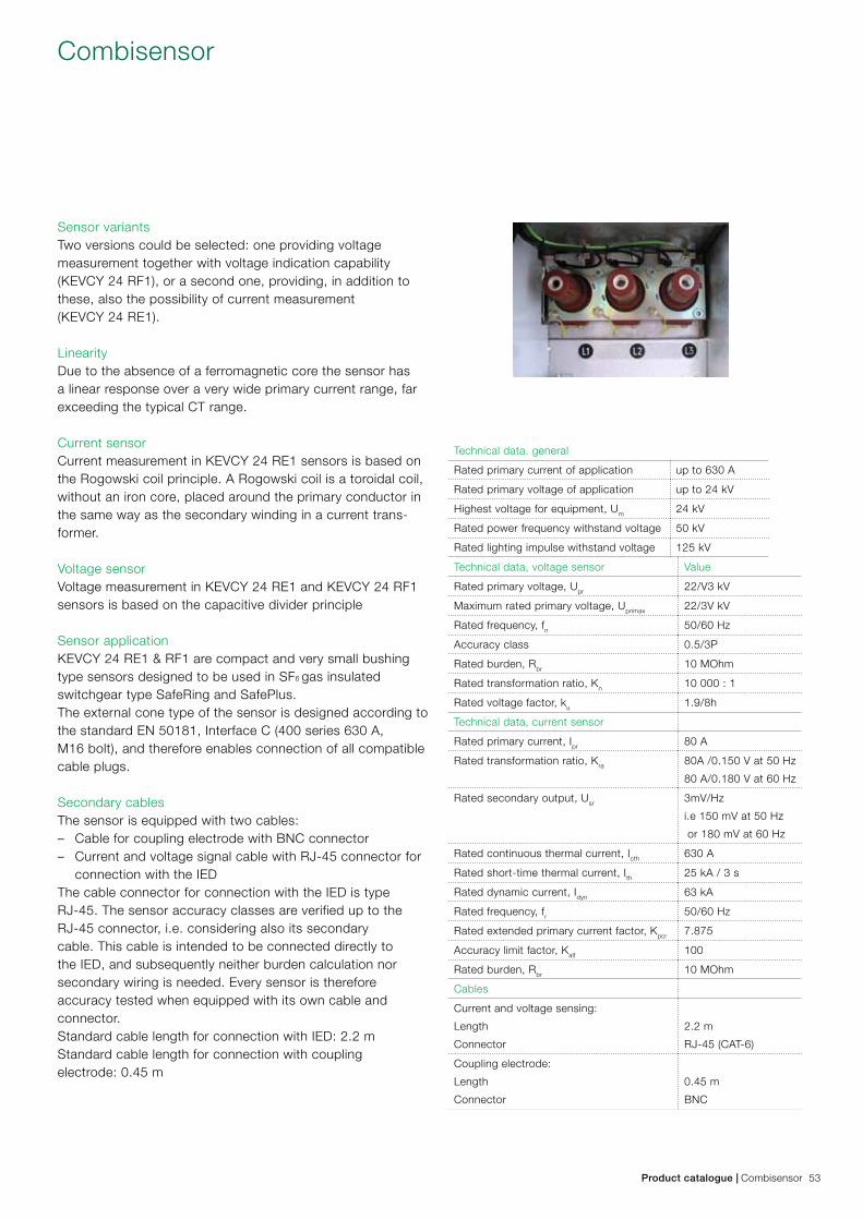
Combisensor
Product catalogue | Combisensor 53
Sensor variantsTwo versions could be selected: one providing voltagemeasurement together with voltage indication capability(KEVCY 24 RF1), or a second one, providing, in addition tothese, also the possibility of current measurement(KEVCY 24 RE1).
LinearityDue to the absence of a ferromagnetic core the sensor has a linear response over a very wide primary current range, far exceeding the typical CT range.
Current sensorCurrent measurement in KEVCY 24 RE1 sensors is based onthe Rogowski coil principle. A Rogowski coil is a toroidal coil,without an iron core, placed around the primary conductor inthe same way as the secondary winding in a current trans-former.
Voltage sensorVoltage measurement in KEVCY 24 RE1 and KEVCY 24 RF1sensors is based on the capacitive divider principle
Sensor applicationKEVCY 24 RE1 & RF1 are compact and very small bushingtype sensors designed to be used in SF6 gas insulatedswitchgear type SafeRing and SafePlus.The external cone type of the sensor is designed according tothe standard EN 50181, Interface C (400 series 630 A,M16 bolt), and therefore enables connection of all compatiblecable plugs.
Secondary cablesThe sensor is equipped with two cables: – Cable for coupling electrode with BNC connector – Current and voltage signal cable with RJ-45 connector for
connection with the IED The cable connector for connection with the IED is typeRJ-45. The sensor accuracy classes are verified up to theRJ-45 connector, i.e. considering also its secondarycable. This cable is intended to be connected directly tothe IED, and subsequently neither burden calculation norsecondary wiring is needed. Every sensor is thereforeaccuracy tested when equipped with its own cable andconnector.Standard cable length for connection with IED: 2.2 mStandard cable length for connection with couplingelectrode: 0.45 m
Technical data. general
Rated primary current of application up to 630 A
Rated primary voltage of application up to 24 kV
Highest voltage for equipment, Um 24 kV
Rated power frequency withstand voltage 50 kV
Rated lighting impulse withstand voltage 125 kV
Technical data, voltage sensor Value
Rated primary voltage, Upr 22/V3 kV
Maximum rated primary voltage, Uprimax 22/3V kV
Rated frequency, fn 50/60 Hz
Accuracy class 0.5/3P
Rated burden, Rbr 10 MOhm
Rated transformation ratio, Kn 10 000 : 1
Rated voltage factor, ku 1.9/8h
Technical data, current sensor
Rated primary current, Ipr 80 A
Rated transformation ratio, Kra 80A /0.150 V at 50 Hz
80 A/0.180 V at 60 Hz
Rated secondary output, Usr 3mV/Hz
i.e 150 mV at 50 Hz
or 180 mV at 60 Hz
Rated continuous thermal current, Icth 630 A
Rated short-time thermal current, Ith 25 kA / 3 s
Rated dynamic current, Idyn 63 kA
Rated frequency, fr 50/60 Hz
Rated extended primary current factor, Kpcr 7.875
Accuracy limit factor, Kalf 100
Rated burden, Rbr 10 MOhm
Cables
Current and voltage sensing:
Length
Connector
2.2 m
RJ-45 (CAT-6)
Coupling electrode:
Length
Connector
0.45 m
BNC
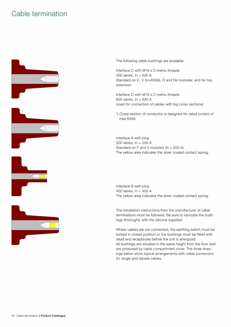
The following cable bushings are available:
Interface C with M16 x 2 metric threads400 series, In = 630 AStandard on C, V (In=630A), D and De modules; and for top extension
Interface D with M16 x 2 metric threads600 series, In = 630 A (used for connection of cables with big cross sections)
*) Cross section of conductor is designed for rated current of max 630A
Interface A with plug200 series, In = 200 AStandard on F and V modules (In = 200 A)The yellow area indicates the silver coated contact spring.
Interface B with plug400 series, In = 400 AThe yellow area indicates the silver coated contact spring.
The installation instructions from the manufacturer of cable terminations must be followed. Be sure to lubricate the bush-ings thoroughly with the silicone supplied.
Where cables are not connected, the earthing switch must be locked in closed position or the bushings must be fitted with dead end receptacles before the unit is energized.All bushings are situated in the same height from the floor and are protected by cable compartment cover. The three draw-ings below show typical arrangements with cable connectors for single and double cables.
Cable termination
54 Cable termination | Product Catalogue
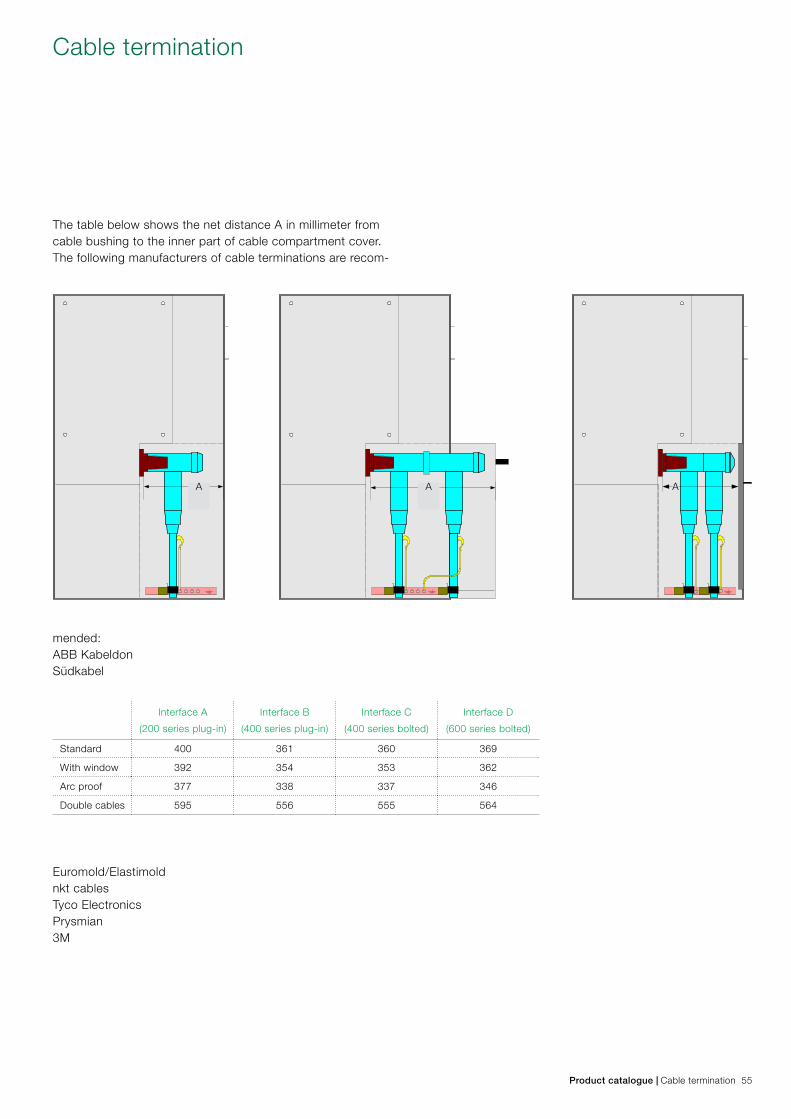
A A A
The table below shows the net distance A in millimeter from cable bushing to the inner part of cable compartment cover.The following manufacturers of cable terminations are recom-
mended:ABB KabeldonSüdkabel
Euromold/Elastimoldnkt cablesTyco ElectronicsPrysmian3M
Interface A
(200 series plug-in)
Interface B
(400 series plug-in)
Interface C
(400 series bolted)
Interface D
(600 series bolted)
Standard 400 361 360 369
With window 392 354 353 362
Arc proof 377 338 337 346
Double cables 595 556 555 564
Cable termination
Product catalogue | Cable termination 55
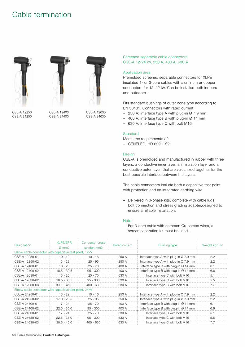
Designation XLPE/EPR
Ø mm2
Conductor cross
section mm2Rated current Bushing type Weight kg/unit
Elbow cable connector with capacitive test point, 12kV
CSE-A 12250-01 10 - 12 10 - 16 250 A Interface type A with plug-in Ø 7.9 mm 2.2
CSE-A 12250-02 13 - 22 25 - 95 250 A Interface type A with plug-in Ø 7.9 mm 2.2
CSE-A 12400-01 13 - 20 25 - 70 400 A Interface type B with plug-in Ø 14 mm 6.1
CSE-A 12400-02 18.5 - 30.5 95 - 300 400 A Interface type B with plug-in Ø 14 mm 6.6
CSE-A 12630-01 13 - 20 25 - 70 630 A Interface type C with bolt M16 5.1
CSE-A 12630-02 18.5 - 30.5 95 - 300 630 A Interface type C with bolt M16 5.5
CSE-A 12630-03 30.5 – 45.0 400 - 630 630 A Interface type C with bolt M16 7.7
Elbow cable connector with capacitive test point, 24kV
CSE-A 24250-01 13 - 22 10 - 16 250 A Interface type A with plug-in Ø 7.9 mm 2.2
CSE-A 24250-02 17.0 - 25.5 25 - 95 250 A Interface type A with plug-in Ø 7.9 mm 2.2
CSE-A 24400-01 17 - 24 25 - 70 400 A Interface type B with plug-in Ø 14 mm 6.1
CSE-A 24400-02 22.5 - 35.0 95 - 300 400 A Interface type B with plug-in Ø 14 mm 6.6
CSE-A 24630-01 17 - 24 25 - 70 630 A Interface type C with bolt M16 5.1
CSE-A 24630-02 22.5 - 35.0 95 - 300 630 A Interface type C with bolt M16 5.5
CSE-A 24630-03 30.5 - 45.0 400 - 630 630 A Interface type C with bolt M16 7.7
Cable termination
56 Cable termination | Product Catalogue
Screened separable cable connectorsCSE-A 12-24 kV, 250 A, 400 A, 630 A
Application areaPremolded screened separable connectors for XLPEinsulated 1- or 3-core cables with aluminum or copperconductors for 12–42 kV. Can be installed both indoorsand outdoors.
Fits standard bushings of outer cone type according toEN 50181. Connectors with rated current: – 250 A: interface type A with plug-in Ø 7.9 mm – 400 A: interface type B with plug-in Ø 14 mm – 630 A: interface type C with bolt M16
StandardMeets the requirements of: – CENELEC, HD 629.1 S2
DesignCSE-A is premolded and manufactured in rubber with three layers; a conductive inner layer, an insulation layer and a conductive outer layer, that are vulcanized together for the best possible interface between the layers.
The cable connectors include both a capacitive test pointwith protection and an integrated earthing wire.
– Delivered in 3-phase kits, complete with cable lugs, bolt connection and stress grading adapter,designed to ensure a reliable installation.
Note: – For 3-core cable with common Cu-screen wires, a
screen separation kit must be used.
CSE-A 12250CSE-A 24250
CSE-A 12400CSE-A 24400
CSE-A 12630CSE-A 24630
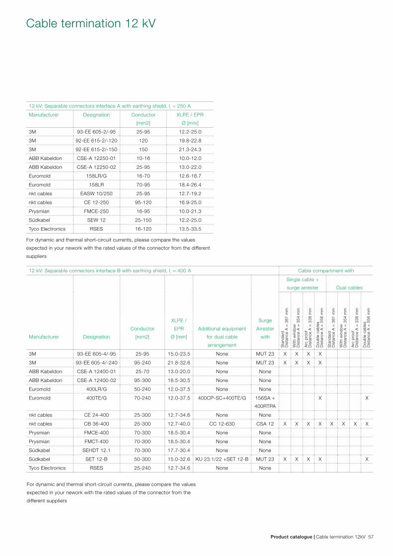
12 kV: Separable connectors interface B with earthing shield, Ir = 400 A Cable compartment with
Manufacturer Designation
Conductor
[mm2]
XLPE /
EPR
Ø [mm]
Additional equipment
for dual cable
arrangement
Surge
Arrester
with
Single cable +
surge arrester Dual cablesS
tand
ard
Dis
tanc
e A
= 3
61 m
m
With
win
dow
Dis
tanc
e A
= 3
54 m
m
Arc
pro
of
Dis
tanc
e A
= 3
38 m
m
Dou
ble
cab
les
Dis
tanc
e A
= 5
56 m
m
Sta
ndar
d D
ista
nce
A =
361
mm
With
win
dow
Dis
tanc
e A
= 3
54 m
m
Arc
pro
of
Dis
tanc
e A
= 3
38 m
m
Dou
ble
cab
les
Dis
tanc
e A
= 5
56 m
m
3M 93-EE 605-4/-95 25-95 15.0-23.5 None MUT 23 X X X X
3M 93-EE 605-4/-240 95-240 21.8-32.6 None MUT 23 X X X X
ABB Kabeldon CSE-A 12400-01 25-70 13.0-20.0 None None
ABB Kabeldon CSE-A 12400-02 95-300 18.5-30.5 None None
Euromold 400LR/G 50-240 12.0-37.5 None None
Euromold 400TE/G 70-240 12.0-37.5 400CP-SC+400TE/G 156SA +
400RTPA
X X
nkt cables CE 24-400 25-300 12.7-34.6 None None
nkt cables CB 36-400 25-300 12.7-40.0 CC 12-630 CSA 12 X X X X X X X X
Prysmian FMCE-400 70-300 18.5-30.4 None None
Prysmian FMCT-400 70-300 18.5-30.4 None None
Südkabel SEHDT 12.1 70-300 17.7-30.4 None None
Südkabel SET 12-B 50-300 15.0-32.6 KU 23.1/22 +SET 12-B MUT 23 X X X X X
Tyco Electronics RSES 25-240 12.7-34.6 None None
12 kV: Separable connectors interface A with earthing shield, Ir = 250 A
Manufacturer Designation Conductor
[mm2]
XLPE / EPR
Ø [mm]
3M 93-EE 605-2/-95 25-95 12.2-25.0
3M 92-EE 615-2/-120 120 19.8-22.8
3M 92-EE 615-2/-150 150 21.3-24.3
ABB Kabeldon CSE-A 12250-01 10-16 10.0-12.0
ABB Kabeldon CSE-A 12250-02 25-95 13.0-22.0
Euromold 158LR/G 16-70 12.6-18.7
Euromold 158LR 70-95 18.4-26.4
nkt cables EASW 10/250 25-95 12.7-19.2
nkt cables CE 12-250 95-120 16.9-25.0
Prysmian FMCE-250 16-95 10.0-21.3
Südkabel SEW 12 25-150 12.2-25.0
Tyco Electronics RSES 16-120 13.5-33.5
For dynamic and thermal short-circuit currents, please compare the values
expected in your nework with the rated values of the connector from the different
suppliers
For dynamic and thermal short-circuit currents, please compare the values
expected in your nework with the rated values of the connector from the
different suppliers
Cable termination 12 kV
Product catalogue | Cable termination 12kV 57
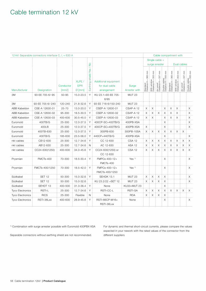
12 kV: Separable connectors interface C, Ir = 630 A Cable compartment with
Manufacturer Designation
Conductor
[mm2]
XLPE /
EPR
Ø [mm] Ear
thin
g sh
ield
Yes
/ N
o
Additional equipment
for dual cable
arrangement
Surge
Arrester with
Single cable +
surge arrester Dual cables
Sta
ndar
d D
ista
nce
A =
360
mm
With
win
dow
Dis
tanc
e A
= 3
53 m
m
Arc
pro
of
Dis
tanc
e A
= 3
37 m
m
Dou
ble
cab
les
Dis
tanc
e A
= 5
55 m
m
Sta
ndar
d D
ista
nce
A =
360
mm
With
win
dow
Dis
tanc
e A
= 3
53 m
m
Arc
pro
of
Dis
tanc
e A
= 3
37 m
m
Dou
ble
cab
les
Dis
tanc
e A
= 5
55 m
m
3M 93-EE 705-6/-95 50-95 15.0-23.5 Y KU 23.1+93-EE 705-
6/95
MUT 23
3M 93-EE 705-6/-240 120-240 21.8-32.6 Y 93-EE 718-6/150-240 MUT 23
ABB Kabeldon CSE-A 12630-01 25-70 13.0-20.0 Y CSEP-A 12630-01 CSAP-A 12 X X X X X X
ABB Kabeldon CSE-A 12630-02 95-300 18.5-30.5 Y CSEP-A 12630-02 CSAP-A 12 X X X X X X X
ABB Kabeldon CSE-A 12630-03 400-630 30.5-45.0 Y CSEP-A 12630-03 CSAP-A 12 X X X X X X
Euromold 400TB/G 25-300 12.0-37.5 Y 400CP-SC+400TB/G 400PB-XSA X X
Euromold 400LB 25-300 12.0-37.5 Y 400CP-SC+400TB/G 400PB-XSA X X X
Euromold 400TB-630 25-300 12.0-37.5 Y 300PB-630 300PB-10SA X X X X X X X
Euromold 400TB/G 185-630 23.5-56.0 Y 440CP+440TB/G 400PB-XSA X X
nkt cables CB12-630 25-300 12.7-34.6 Y CC 12-630 CSA 12 X X X X X X X X
nkt cables AB12-630 25-300 12.7-34.6 N AC 12-630 ASA 12 X X X X X X X X
nkt cables CC24-630(1250) 400-630 34.0-45.6 Y CC24-630(1250) or
CC 12-630
CSA 12 X X X X X X X X
Prysmian FMCTs-400 70-300 18.5-30.4 Y FMPCs-400-12+
FMCTs-400
Yes 1) X X
Prysmian FMCTs-400/1250 70-300 18.5-42.0 Y FMPCs-400-12+
FMCTs-400/1250
Yes 1) X X
Südkabel SET 12 50-300 15.0-32.6 Y SEHDK 13.1 MUT 23 X X X X X
Südkabel SET 12 50-300 15.0-32.6 KU 23.2/22 +SET 12 MUT 23 X X X X X
Südkabel SEHDT 13 400-500 31.3-36.4 Y None KU33+MUT 23 X
Tyco Electronics RSTI-L 25-300 12.7-34.6 Y RSTI-CC-L RSTI-SA X X X X X X X X
Tyco Electronics RICS 25-300 Flexible N None RDA X X X X
Tyco Electronics RSTI-36Lxx 400-630 28.9-45.6 Y RSTI-66CP-M16+
RSTI-36Lxx
None X X
1) Combination with surge arrester possible with Euromold 400PBX-XSA
Separable connectors without earthing shield are not recommended.
For dynamic and thermal short-circuit currents, please compare the values
expected in your nework with the rated values of the connector from the
different suppliers
Cable termination 12 kV
58 Cable termination 12kV | Product Catalogue
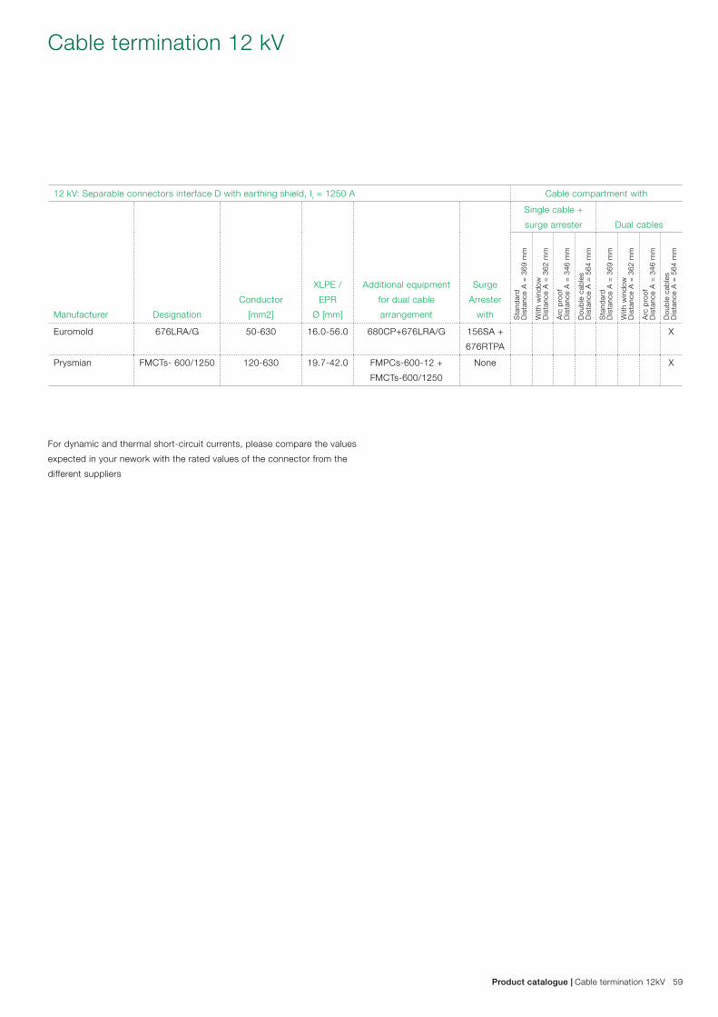
12 kV: Separable connectors interface D with earthing shield, Ir = 1250 A Cable compartment with
Manufacturer Designation
Conductor
[mm2]
XLPE /
EPR
Ø [mm]
Additional equipment
for dual cable
arrangement
Surge
Arrester
with
Single cable +
surge arrester Dual cables
Sta
ndar
d D
ista
nce
A =
369
mm
With
win
dow
Dis
tanc
e A
= 3
62 m
m
Arc
pro
of
Dis
tanc
e A
= 3
46 m
m
Dou
ble
cab
les
Dis
tanc
e A
= 5
64 m
m
Sta
ndar
d D
ista
nce
A =
369
mm
With
win
dow
Dis
tanc
e A
= 3
62 m
m
Arc
pro
of
Dis
tanc
e A
= 3
46 m
m
Dou
ble
cab
les
Dis
tanc
e A
= 5
64 m
m
Euromold 676LRA/G 50-630 16.0-56.0 680CP+676LRA/G 156SA +
676RTPA
X
Prysmian FMCTs- 600/1250 120-630 19.7-42.0 FMPCs-600-12 +
FMCTs-600/1250
None X
For dynamic and thermal short-circuit currents, please compare the values
expected in your nework with the rated values of the connector from the
different suppliers
Cable termination 12 kV
Product catalogue | Cable termination 12kV 59
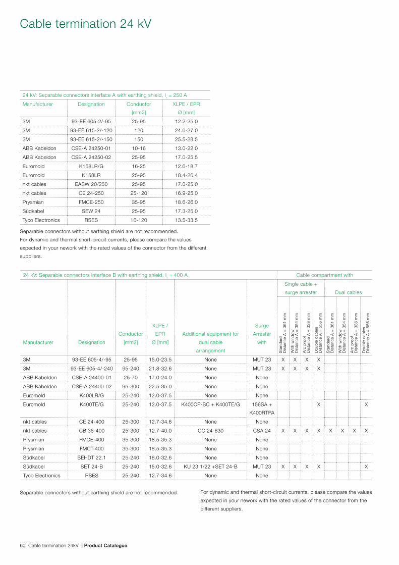
24 kV: Separable connectors interface A with earthing shield, Ir = 250 A
Manufacturer Designation Conductor
[mm2]
XLPE / EPR
Ø [mm]
3M 93-EE 605-2/-95 25-95 12.2-25.0
3M 93-EE 615-2/-120 120 24.0-27.0
3M 93-EE 615-2/-150 150 25.5-28.5
ABB Kabeldon CSE-A 24250-01 10-16 13.0-22.0
ABB Kabeldon CSE-A 24250-02 25-95 17.0-25.5
Euromold K158LR/G 16-25 12.6-18.7
Euromold K158LR 25-95 18.4-26.4
nkt cables EASW 20/250 25-95 17.0-25.0
nkt cables CE 24-250 25-120 16.9-25.0
Prysmian FMCE-250 35-95 18.6-26.0
Südkabel SEW 24 25-95 17.3-25.0
Tyco Electronics RSES 16-120 13.5-33.5
24 kV: Separable connectors interface B with earthing shield, Ir = 400 A Cable compartment with
Manufacturer Designation
Conductor
[mm2]
XLPE /
EPR
Ø [mm]
Additional equipment for
dual cable
arrangement
Surge
Arrester
with
Single cable +
surge arrester Dual cables
Sta
ndar
d D
ista
nce
A =
361
mm
With
win
dow
Dis
tanc
e A
= 3
54 m
m
Arc
pro
of
Dis
tanc
e A
= 3
38 m
m
Dou
ble
cab
les
Dis
tanc
e A
= 5
56 m
m
Sta
ndar
d D
ista
nce
A =
361
mm
With
win
dow
Dis
tanc
e A
= 3
54 m
m
Arc
pro
of
Dis
tanc
e A
= 3
38 m
m
Dou
ble
cab
les
Dis
tanc
e A
= 5
56 m
m
3M 93-EE 605-4/-95 25-95 15.0-23.5 None MUT 23 X X X X
3M 93-EE 605-4/-240 95-240 21.8-32.6 None MUT 23 X X X X
ABB Kabeldon CSE-A 24400-01 25-70 17.0-24.0 None None
ABB Kabeldon CSE-A 24400-02 95-300 22.5-35.0 None None
Euromold K400LR/G 25-240 12.0-37.5 None None
Euromold K400TE/G 25-240 12.0-37.5 K400CP-SC + K400TE/G 156SA +
K400RTPA
X X
nkt cables CE 24-400 25-300 12.7-34.6 None None
nkt cables CB 36-400 25-300 12.7-40.0 CC 24-630 CSA 24 X X X X X X X X
Prysmian FMCE-400 35-300 18.5-35.3 None None
Prysmian FMCT-400 35-300 18.5-35.3 None None
Südkabel SEHDT 22.1 25-240 18.0-32.6 None None
Südkabel SET 24-B 25-240 15.0-32.6 KU 23.1/22 +SET 24-B MUT 23 X X X X X
Tyco Electronics RSES 25-240 12.7-34.6 None None
Separable connectors without earthing shield are not recommended.
For dynamic and thermal short-circuit currents, please compare the values
expected in your nework with the rated values of the connector from the different
suppliers.
Separable connectors without earthing shield are not recommended. For dynamic and thermal short-circuit currents, please compare the values
expected in your nework with the rated values of the connector from the
different suppliers.
Cable termination 24 kV
60 Cable termination 24kV | Product Catalogue
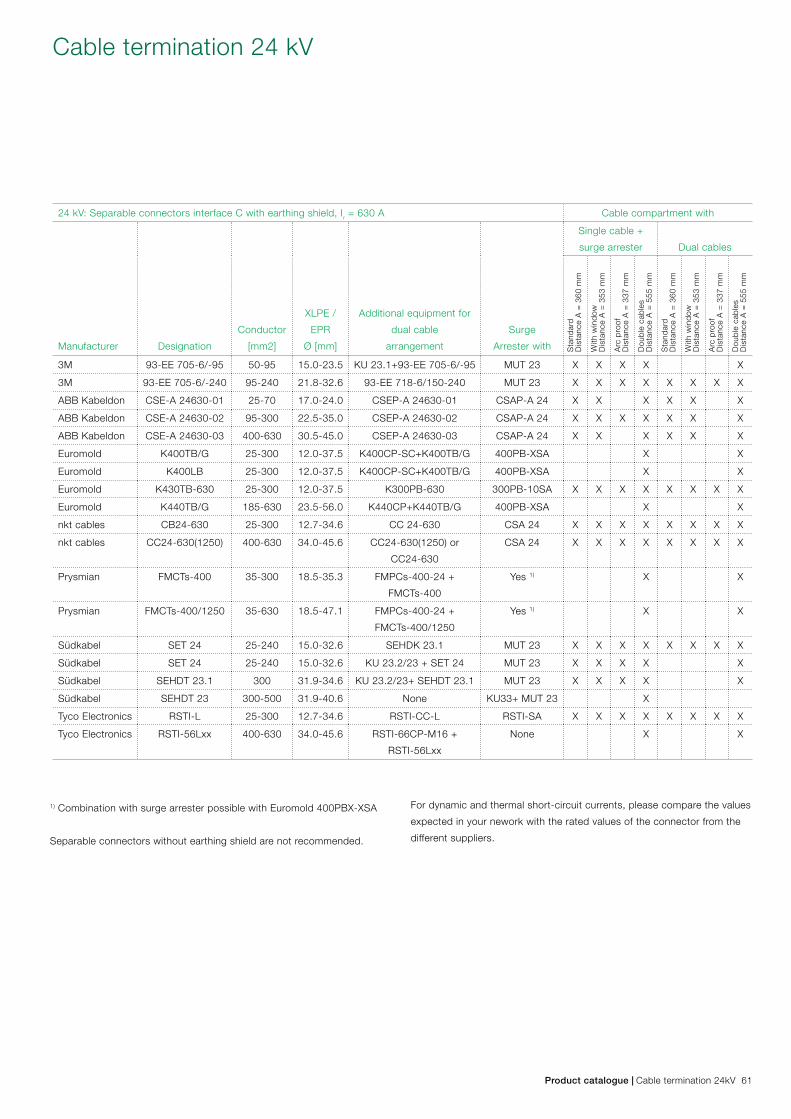
24 kV: Separable connectors interface C with earthing shield, Ir = 630 A Cable compartment with
Manufacturer Designation
Conductor
[mm2]
XLPE /
EPR
Ø [mm]
Additional equipment for
dual cable
arrangement
Surge
Arrester with
Single cable +
surge arrester Dual cables
Sta
ndar
d D
ista
nce
A =
360
mm
With
win
dow
Dis
tanc
e A
= 3
53 m
m
Arc
pro
of
Dis
tanc
e A
= 3
37 m
m
Dou
ble
cab
les
Dis
tanc
e A
= 5
55 m
m
Sta
ndar
d D
ista
nce
A =
360
mm
With
win
dow
Dis
tanc
e A
= 3
53 m
m
Arc
pro
of
Dis
tanc
e A
= 3
37 m
m
Dou
ble
cab
les
Dis
tanc
e A
= 5
55 m
m
3M 93-EE 705-6/-95 50-95 15.0-23.5 KU 23.1+93-EE 705-6/-95 MUT 23 X X X X X
3M 93-EE 705-6/-240 95-240 21.8-32.6 93-EE 718-6/150-240 MUT 23 X X X X X X X X
ABB Kabeldon CSE-A 24630-01 25-70 17.0-24.0 CSEP-A 24630-01 CSAP-A 24 X X X X X X
ABB Kabeldon CSE-A 24630-02 95-300 22.5-35.0 CSEP-A 24630-02 CSAP-A 24 X X X X X X X
ABB Kabeldon CSE-A 24630-03 400-630 30.5-45.0 CSEP-A 24630-03 CSAP-A 24 X X X X X X
Euromold K400TB/G 25-300 12.0-37.5 K400CP-SC+K400TB/G 400PB-XSA X X
Euromold K400LB 25-300 12.0-37.5 K400CP-SC+K400TB/G 400PB-XSA X X
Euromold K430TB-630 25-300 12.0-37.5 K300PB-630 300PB-10SA X X X X X X X X
Euromold K440TB/G 185-630 23.5-56.0 K440CP+K440TB/G 400PB-XSA X X
nkt cables CB24-630 25-300 12.7-34.6 CC 24-630 CSA 24 X X X X X X X X
nkt cables CC24-630(1250) 400-630 34.0-45.6 CC24-630(1250) or
CC24-630
CSA 24 X X X X X X X X
Prysmian FMCTs-400 35-300 18.5-35.3 FMPCs-400-24 +
FMCTs-400
Yes 1) X X
Prysmian FMCTs-400/1250 35-630 18.5-47.1 FMPCs-400-24 +
FMCTs-400/1250
Yes 1) X X
Südkabel SET 24 25-240 15.0-32.6 SEHDK 23.1 MUT 23 X X X X X X X X
Südkabel SET 24 25-240 15.0-32.6 KU 23.2/23 + SET 24 MUT 23 X X X X X
Südkabel SEHDT 23.1 300 31.9-34.6 KU 23.2/23+ SEHDT 23.1 MUT 23 X X X X X
Südkabel SEHDT 23 300-500 31.9-40.6 None KU33+ MUT 23 X
Tyco Electronics RSTI-L 25-300 12.7-34.6 RSTI-CC-L RSTI-SA X X X X X X X X
Tyco Electronics RSTI-56Lxx 400-630 34.0-45.6 RSTI-66CP-M16 +
RSTI-56Lxx
None X X
1) Combination with surge arrester possible with Euromold 400PBX-XSA
Separable connectors without earthing shield are not recommended.
For dynamic and thermal short-circuit currents, please compare the values
expected in your nework with the rated values of the connector from the
different suppliers.
Cable termination 24 kV
Product catalogue | Cable termination 24kV 61
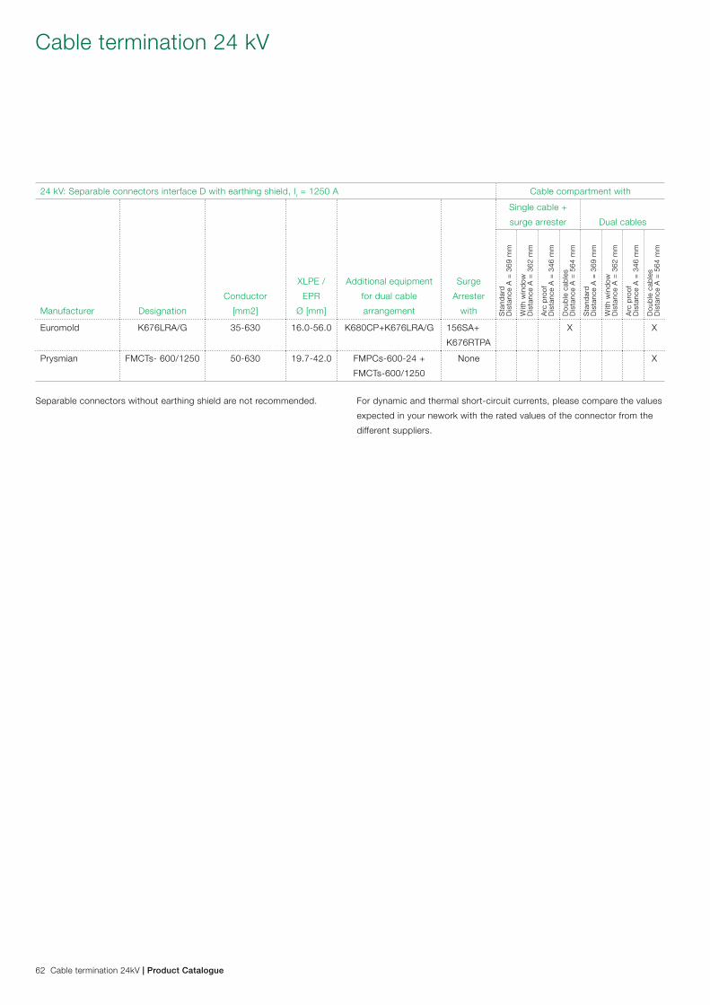
24 kV: Separable connectors interface D with earthing shield, Ir = 1250 A Cable compartment with
Manufacturer Designation
Conductor
[mm2]
XLPE /
EPR
Ø [mm]
Additional equipment
for dual cable
arrangement
Surge
Arrester
with
Single cable +
surge arrester Dual cables
Sta
ndar
d D
ista
nce
A =
369
mm
With
win
dow
Dis
tanc
e A
= 3
62 m
m
Arc
pro
of
Dis
tanc
e A
= 3
46 m
m
Dou
ble
cab
les
Dis
tanc
e A
= 5
64 m
m
Sta
ndar
d D
ista
nce
A =
369
mm
With
win
dow
Dis
tanc
e A
= 3
62 m
m
Arc
pro
of
Dis
tanc
e A
= 3
46 m
m
Dou
ble
cab
les
Dis
tanc
e A
= 5
64 m
m
Euromold K676LRA/G 35-630 16.0-56.0 K680CP+K676LRA/G 156SA+
K676RTPA
X X
Prysmian FMCTs- 600/1250 50-630 19.7-42.0 FMPCs-600-24 +
FMCTs-600/1250
None X
Separable connectors without earthing shield are not recommended. For dynamic and thermal short-circuit currents, please compare the values
expected in your nework with the rated values of the connector from the
different suppliers.
Cable termination 24 kV
62 Cable termination 24kV | Product Catalogue
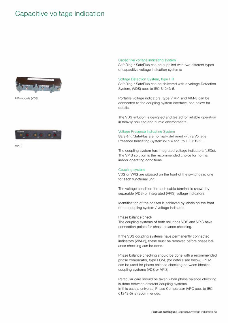
Capacitive voltage indicating systemSafeRing / SafePlus can be supplied with two different types of capacitive voltage indication systems:
Voltage Detection System, type HRSafeRing / SafePlus can be delivered with a voltage Detection System, (VDS) acc. to IEC 61243-5.
Portable voltage indicators, type VIM-1 and VIM-3 can be connected to the coupling system interface, see below for details.
The VDS solution is designed and tested for reliable operation in heavily polluted and humid environments.
Voltage Presence Indicating SystemSafeRing/SafePlus are normally delivered with a Voltage Presence Indicating System (VPIS) acc. to IEC 61958.
The coupling system has integrated voltage indicators (LEDs). The VPIS solution is the recommended choice for normal indoor operating conditions.
Coupling systemVDS or VPIS are situated on the front of the switchgear, one for each functional unit.
The voltage condition for each cable terminal is shown by separable (VDS) or integrated (VPIS) voltage indicators.
Identification of the phases is achieved by labels on the front of the coupling system / voltage indicator.
Phase balance checkThe coupling systems of both solutions VDS and VPIS have connection points for phase balance checking.
If the VDS coupling systems have permanently connected indicators (VIM-3), these must be removed before phase bal-ance checking can be done.
Phase balance checking should be done with a recommended phase comparator, type PCM, (for details see below). PCM can be used for phase balance checking between identical coupling systems (VDS or VPIS).
Particular care should be taken when phase balance checking is done between different coupling systems. In this case a universal Phase Comparator (VPC acc. to IEC 61243-5) is recommended.
Capacitive voltage indication
HR-module (VDS)
VPIS
Product catalogue | Capacitive voltage indication 63
Phase comparators type PCMThe PCM-phase comparator indicates phase balance / unbalance between two cubicles. To be used in capacitive Coupling systems, acc. to IEC 61243-5 and/or IEC 61958.
Special featuresNo external power supply required.Voltage indication by flashing LED.Fully insulated system (IP 68) with cast resin.Function test 230 V AC or test-equipment “MAXTEST - S”
Technical data VIM 1 and VIM 3
Rated frequency 50 / 60 Hz
Treshold voltage U 70 - 90V
Treshold current I 1,62 - 2,5 uA
Capacity to coupling system 74 - 88 pF
Input impedance of indicator 36 - 43,2 MOhm
Operating temperature -25 - +55oC
Enclosure protection IP 68
Dimensions VIM 1, w x h x d, excl. connectors 43 x 22 x 30 mm
Dimensions VIM 3, w x h x d, excl. connectors 144 x 28 x 30 mm
Weight VIM 1 40 g
Weight VIM 3 110 g
Technical data PCM
Rated frequency 50 Hz
Length of test lead 1,4 m
Operating temperature -25 - +55oC
Dimensions, w x h x d, excl. connectors 43 x 22 x 20 mm
Enclosure protection IP 68
Weight 40 g
Voltage indicators VIM 1 and VIM 3 for HR-moduleThe voltage indicators VIM 1 and VIM 3 are used with capaci-tive outlets based on HR-system, to indicate high voltage in a switchgear. VIM 1 and VIM 3 fulfil the test requirements of IEC 61243-5. The indicators can be delivered in two versions: VIM 1 for voltage indication in one phase at a time, mobile unit, or VIM 3 for voltage indication in three phases, prepared for permanent mounting in the switchgear.
Special featuresNo external power supply requiredVoltage indication by red flashing LED’s.Fully insulated system (IP 68) with cast resin and safety pin.Function test: e.g. test equipment “ MAXTEST - S”
Capacitive voltage indication
VIM 3
VIM 1
PCM
64 Capacitive voltage indication | Product Catalogue
Horstmann SIGMA Short-circuit IndicatorThe SIGMA short-circuit indicator is designed for distribution networks using radial or open-ring operation. The instrument is provided with three short-circuit current transformers which are mounted onto the bushings of the switchgear. When the phase current exceeds the preset trip level, the fault-affected phase is indicated by a bright LED flashlight as the remote signal contact gets activated. If a second tripping occurs within a preset time, for example when automatic re-closing is in process, this condition is indicated by a double flashing LED.
Short-circuit trip currents (Ik) adjustable to 200, 300, 400, 600, 800 or 1000A, or self-asjusting
Response time 40 ms or 80 ms
Timed reset after passage of 1, 2, 4 or 8 h
Remote test/remote reset via external potential-free momentary contact
Temperature range -30oC... +70oC
Energy supply long-life lithium cell, life expectancy 20 years, flashing time >1000 h
Relay contact permanent or momentary contact (1s), adjustable
Horstmann SIGMA F+E 3 Short-circuit and Earth Fault IndicatorThe SIGMA F+E 3 short-circuit and earth fault indicator pro-vides the same functions as the SIGMA type. Three cable-type current transformers are used for short-circuit and earth fault detection. The overcurrent (I>>) is indicated by a red LED whereas a yellow LED signals the earth fault current (IE).
Trip currents (Ik) adjustable to 200, 300, 400, 600, 800, 1000 or 2000A, or self-asjusting
Trip currents (I0) adjustable to 20, 40, 60, 80, 100, 120 or 190 A
Response delay (Ik/I0) 40, 80, 200, 300 ms/ 80, 160, 200, 300 ms
Timed reset after passage of 1, 2, 4 or 8 h
Remote test/remote reset via external potential-free momentary contact
Temperature range -30oC... +70oC
Energy supply internal:by long-life lithium cell, life expectancy 20 years, total flashing time >1000h; external:by 12-60VDC (optional feature)
Relay contact permanent or momentary contact (1s), adjustable
Short-circuit indicator
Product catalogue | Short-circuit indicator 65
Horstmann ComPass A Short-circuit and Earth Fault IndicatorThe ComPass A is a combined short-circuit and earth fault indicator along with the feature of load current measure-ment. It can be operated in radial and open ring distribution networks. Three cable-type current transformers are used to detect short-circuits and earth faults, and to measure the load current. The ComPass A permanently measures the phase currents and indicates either the earth fault or the short-circuit on the display once the trip levels have been exceeded. Be-sides the permanent indications of the actual load current and frequency values, this design also allows for active storage of load current data in the form of maximum values measured in the last 24 hours and 365 days. RS-485/modbus interface can be used to remotely indicate and to read the relevant data.
Horstmann ComPass B Directional Short-circuit and Directional Earth Fault IndicatorThe ComPass B instrument provides the same functions as the ComPass A. The ComPass B also features directional detection of short-circuits and directional detection of earth faults in all networks//neutral earthing connections, and moreover the indication of the load flow direction.
Trip currents (Ik/I0) 50 A - 2000 A / 20 A - 1000 A
Delay time (Ik/I0) 40 ms < t < 60 ms
Time reset 1 min - 24 h
Remote test/remote reset via external potential-free momentary contact
Temperature range -30oC... +70oC
Energy supply external: by 24 - 230V AC/DC; internal: by back-up supply
Relay contact permanent or momentary contact (1s),selectable
Horstmann ALPHA E Short-circuit IndicatorThis instrument is designed for distribution networks using radial or open-ring operation.It is provided with three short-circuit current transformers which are mounted onto the bushings of the switchgear. In the event of a fault, a mechanical flag is operated to signal that the phase current has exceeded the preset trip level.
Trip currents (Ik) adjustable to 400, 600, 800 or 1000 A
Delay time (Ik) 100 ms
Timed reset after passage of 2 or 4 h
Remote test/remote reset 12 - 60 V AC/DC
Temperature range -30oC... +70oC
Energy supply log-life lithium cell
Relay contact permanent or momentary contact (100 ms)
Short-circuit indicator
66 Short-circuit indicator | Product Catalogue
A B
1)
A B
2)
A B
3)
A B
4)
Except for fuse-switch and vacuum circuit-breaker, all load break switches, earthing switches and disconnectors may be equipped with Ronis key interlock type EL11AP for one key.Earthing switches can also be equipped with EL22AP for 2 keys.
Ronis key interlocks can be used as follow: Two switchgears A and B are connected to each other by cables. The purpose of interlocks is to prevent closing of the earthing switch un-less the load break switch in the other switchgear is locked in open position.
1) One Ronis key interlock will be mounted close to the operating shaft of the load break switch in switchgear A. An identical Ronis key interlock will be mounted close to the operating shaft of the earthing switch in switchgear B. As long as the load break switch in switchgear A is in closed position, it will be impossible to remove or operate the key in the key interlock.
2) First you have to operate the load break switch in switch-gear A to open position. Then it will be possible to operate the key interlock and turn the key which extends the locking bolt. This will prevent the access to the operating shaft of the load break switch. Then withdraw the key and insert it into the identical key inter-lock on the earthing switch of switchgear B.
3) When the key is inserted, you will be able to operate the key interlock and turn the key which will withdraw the extend-ed locking bolt. Then there will be access to operate the earthing switch to closed position. As long as the earthing switch is in closed position, the key will be captured and make it impossible to close the load break switch in switchgear A.
4) If the load break switch in switchgear B and earthing switch in switchgear A are equipped with another identical Ronis key interlock which has a different key combination than de-scribed above, it will be impossible to make an earth connec-tion of an incoming energized cable from neither switchgear A nor B.
Another example for use of Ronis key interlocks is to prevent access to the distribution transformer before the primary side of the transformer is connected to earth. This can be solved by means of two identical Ronis key interlocks; one mounted on the earthing switch for the distribution transformer feeder and the other one on the door in front of the transformer.
Ronis key interlock
Product catalogue | Ronis key interlock 67
Smart Grid applications
68 Smart Grid applications | Product Catalogue
SafeRing/SafePlus for Smart Grid applications12-24 kV SafeRing/SafePlus Ring Main Unit portfolio from ABB is now enhanced to meet the increasing demand for Smart Grid applications in secondary distribution networks.
Standard grid automation devices for ABB’s Ring Main Units are located in the space behind the lower front cover, hence eliminating the need for additional low voltage compartment on the top of the switchgear.
Thanks to the flexibility of SafeRing/SafePlus modules, grid automation solutions can also be delivered with different switchgear configurations with low voltage compartment if required.
Standard packages for Smart Grid applications can provide monitoring, control, diagnostic and supervision functionalities including feeder automation devices with wired and/or wireless communication interfaces and power supply back-up.
The already compact SafeRing/SafePlus range can also be delivered as an ultra-compact unit with integrated Smart Grid solutions (reduced overall height of 1’100 mm) to be fitted inside substations with height limitations.
Customer benefitsThe integrated smart grid functionalities enable the network operators to: – Monitor the grid so that they are able to remotely locate
the fault. – Reconfigure the network so that the faulty part of the
network is disconnected. – Reconfigure the network so that the energy loss is
minimized and/or achieve savings for future investments.
Additional benefits for utilities and energy consumers are: – Improved quality of the power supply. – Less and shorter outages and improved voltage quality. – Ensured safety for personnel. – Enhanced operational efficiency and network stability. – Improved tools for the network operators and the field
crews. – Less need to travel to locations with difficult access.
Smart Grid applications
Product catalogue | Smart Grid applications 69
Ring Main Unit for Smart Grid applications is equipped with advanced Feeder Automation device, which in cooperation with additional devices (e.g. Fault Passage Indicators) provides various data to the remote control centers. Key functions of all standard packages from factory are described in the next pages. There are seven different selections which give the end users possibility to adjust the package to fit their requirements.
All secondary devices within the Ring Main Unit are powered by a 24V DC battery. The battery is charged by its charger, which needs external power supply: – 90...264V AC 50/60 Hz or 85...200V DC in case of Feeder
Automation device REC603 (internal battery charger) is used. – 94...132V AC or 184...264V AC 50/60 Hz in case of
Feeder Automation device RTU560CIG10 (external battery charger) is used. Please contact us in case you need other main power supply option.
Remote and local communication A. Remote communication (communication to the remote control center)Default delivery (standard package solution) comes with IEC 60870-5-104 remote communication protocol imple- mentation. The communication media is either wired Ethernet and/or wireless (GSM/GPRS) communication. Please contact us in case you need other remote communi-cation protocol option.
B. Local communication (communication between different automation devices within the RMU) The signals from the Ring Main Unit switches, Fault Passage Indicators and low voltage multi-meters are brought to the Feeder Automation device by two different ways: – digital signals (e.g. switch positions indication and control)
are hardwired – analog signals (e.g. measurements from the Fault
Passage Indicators and low voltage multi-meters) are obtained over local communication bus which can be serial Modbus RTU or serial IEC 60870-5-101 communication protocol. Modbus RTU is used within Diagnostic package together with RTU560CIG10 Feeder Automation device (via it’s CPA port), IEC 60870-5-101 is used for connecting low voltage multi-meters in case REC603 Feeder Automstion device (via its RS1/RS2 ports).
Smart Grid applications
70 Smart Grid applications | Product Catalogue
Packages All standard packages include: – Power supply backup source for automation devices
(24V DC batteries and battery charger) – Wire (Ethernet) and/or wireless (GSM/GPRS) communi-
cation interfaces (SIM card is not part of delivery) – IEC 60870-5-104 host (slave) communication protocol
Three levels of automation packages are defined below. There are additional options which can be selected for each package.
Main selections and their options are (*) default values) 1. Automation level – Remote Monitoring package – Remote Control package*)
– Remote Diagnostic package
2. Feeder automation device – REC603 *)
– RTU560CIG10 GPRS communication/modem: - No *)
- RER601 - 560MDD10
3. MV network fault types – OC and EF directional – OC and EF non directional *)
– Fault
4. Fault passage indicators – Kries - IKI-50_1F (directional) – Horstmann - ComPass B (directional) – Kries - IKI-20U2 *)
– Horstmann - SIGMA F+E (AC/DC)
5. Fault passage indicators remote reset – No – Yes *)
6. Distribution transformer feeders common remote emergency trip – No – Yes *)
7. Supervision of the LV side of the distribution transformer – None *)
– Vamp: WIMO 6CP10 – Circutor: CVM-MINI-ITF-RS485-C2
Options description 1. Automation level The three automation levels (packages) are described below.
Remote Monitoring This package provides remote monitoring of: – The position of load break switches in C modules
(-> grid topology supervision) – Fault passage indicator fault signalization
(-> fast fault localization, reduced outage time, efficient use of manpower) – Faults in the transformer feeders
Remote Control This package includes the features from the Remote Monitoring package and in addition provides: – Remote control of load break switches in C modules
(-> fast fault isolation, fast restoration of healthy part of the MV network , operator safety)
Remote Diagnostic This package includes the features from the Remote Control package and in addition provides: – MV network analog data values such as: currents,
voltages, frequency, power, energy, load flow direction etc. (-> improved notification of overloaded equipment, better maintenance planning, improved power quality).
Note: There are spare inputs (1 – 5 pieces) which can be used for additional customer specified „digital/binary” signals such as: SF6 gas pressure signal, low voltage fuses tripped signal, transformer overheating signal, etc. The number of spare in-puts depends on configuration of Ring Main Unit (CCF, CCCF etc.) and on the type of fault detection for the MV network.
2. Feeder automation device Compact Feeder Automation devices secure remote monitoring and control of the secondary substations in the distribution network. It enables the network control centers to monitor and control the field devices over the different communication infrastructure.
REC603 The Wireless Controller REC603 is a compact, solution based device for the remote control and monitoring of secondary substations such as network disconnectors, load break switches and Ring Main Units in distribution networks.
Product catalogue | Smart Grid applications 71
Smart Grid applications
REC603 enables the network control system to monitor and control the field devices over the public communication infra-structure (GPRS). The Wireless Controller REC603 utilizes the built-in GPRS for reliable and secure end-to-end communi-cation providing remote monitoring and control of up to three objects.
RTU560CIG10 The RTU560 DIN rail provides advanced functionality and makes it the perfect fit for existing and future Grid Automa-tion solutions. The compact housing with the possibility to integrate hardwired information fulfills complex requirements and space restrictions at the same time.
3. MV network fault types Different signals from Fault Passage Indicators can be transmitted to the control centers. These are selected based on type of the MV network (isolated neutral, compensated neutral, high resistance earthing, low resistance earthing or solidly earthing).
Available options are: OC and EF directional With this selection, two different types of events can be transferred to the remote control centers: – Fault in forward direction (does not differentiate over-
current and earth fault) – Fault in backward direction (does not differentiate over-
current and earth fault)
OC and EF non directional With this selection, two different types of events can be transferred to the remote control centers: – Over-current fault (does not differentiate fault direction) – Earth fault (does not differentiate fault direction)
Fault With this selection, one type of event can be transferred to the remote control centers: – Fault (does not differentiate over-current and earth fault nor
fault direction)
4. Fault Passage Indicators Fault Passage Indicators are devices which detect faults in the MV network. Some of them are also able to provide MV analog value measurements to the Feeder Automation device which transfers these signals to the control centers.
5. Fault passage indicators remote reset Selection No The Fault Passage Indicators signalization will be reset according to its setting (e.g. manually, automatically after fixed set time).
Selection Yes This option gives possibility to reset Fault Passage Indicators remotely from the control centers.
Note: There is one common reset command for all Fault Passage Indicators by use of REC603 Feeder Automation device – all Fault Passage Indicators within the Ring Main Unit will be reset at the same time.
6. Distribution transformer feeders common remote emergency trip Selection No No possibility to remotely trip distribution transformers modules.
Selection Yes This option gives possibility to remotely trip distribution transformers modules (usually F and/or V modules) from the control centers.
Note: There is one common trip command for all distribution transformer modules – all modules will be tripped at the same time.
7. Supervision of the LV side of the distribution transformer This option gives possibility to remotely supervise secondary (Low Voltage) side of the distribution transformer. Different multi-function monitoring devices with extensive measuring and calculation functions will be available in this selection. The unit measures currents, voltages and frequencies, and calculates power and energy values. Interconnection cable between Feeder Automation device and low voltage multi-meters is not part of delivery.
None No possibility to remotely supervise LV network analog data.
Vamp: WIMO 6CP10 WIMO 6CP10 secondary substation measuring and monitor-ing unit is a compact multi-function monitoring device with extensive measuring and calculation functions. WIMO 6CP10 is ideal for secondary substation measuring and monitoring management. The unit measures currents, voltages and fre-quencies, and calculates power and energy values.
72 Smart Grid applications | Product Catalogue
Smart Grid applications
Product catalogue | Smart Grid applications 73
Smart Grid applications
Circutor: CVM-MINI-ITF-RS485-C2 The CVM-MINI panel analyzer is a programmable measur-ing instrument; it offers a series of options, which may be selected from configuration menus on the instrument itself.
The CVM-MINI measures, calculates and displays the main electrical parameters for three-phase, balanced or unbal-anced industrial systems.
Measurements are taken as true effective values using the three alternating and neutral voltage inputs and three current inputs to measure In /1A or In /5A secondary from external measurement transformers. The CVM-MINI allows the display of all electrical parameters, using the backlit LCD display, showing three instant electrical parameters, maximum or minimum on each page jump. Note: The availability depends on the selected Feeder Automation device and Ring Main Unit module configuration. These devices are by default mounted in top entry box or low voltage compartment.
��SafePlus
� �� SafeRing
� �SafeRing
� ��SafePlus
696371
1346 1671
� ��SafeRing
1021
595
107
107
325 325
79107
107
107107
Dimensions
74 Dimensions | Product Catalogue
VD4
SafePlus� ��
� �� REF541
696
� ��SafePlus
69656
1336
1806
802
SAFEPLUS
VD4
244
150
152150
595
Product catalogue | Dimensions 75
Dimensions
Metering module M, front view Metering module M,side view right
CB modul
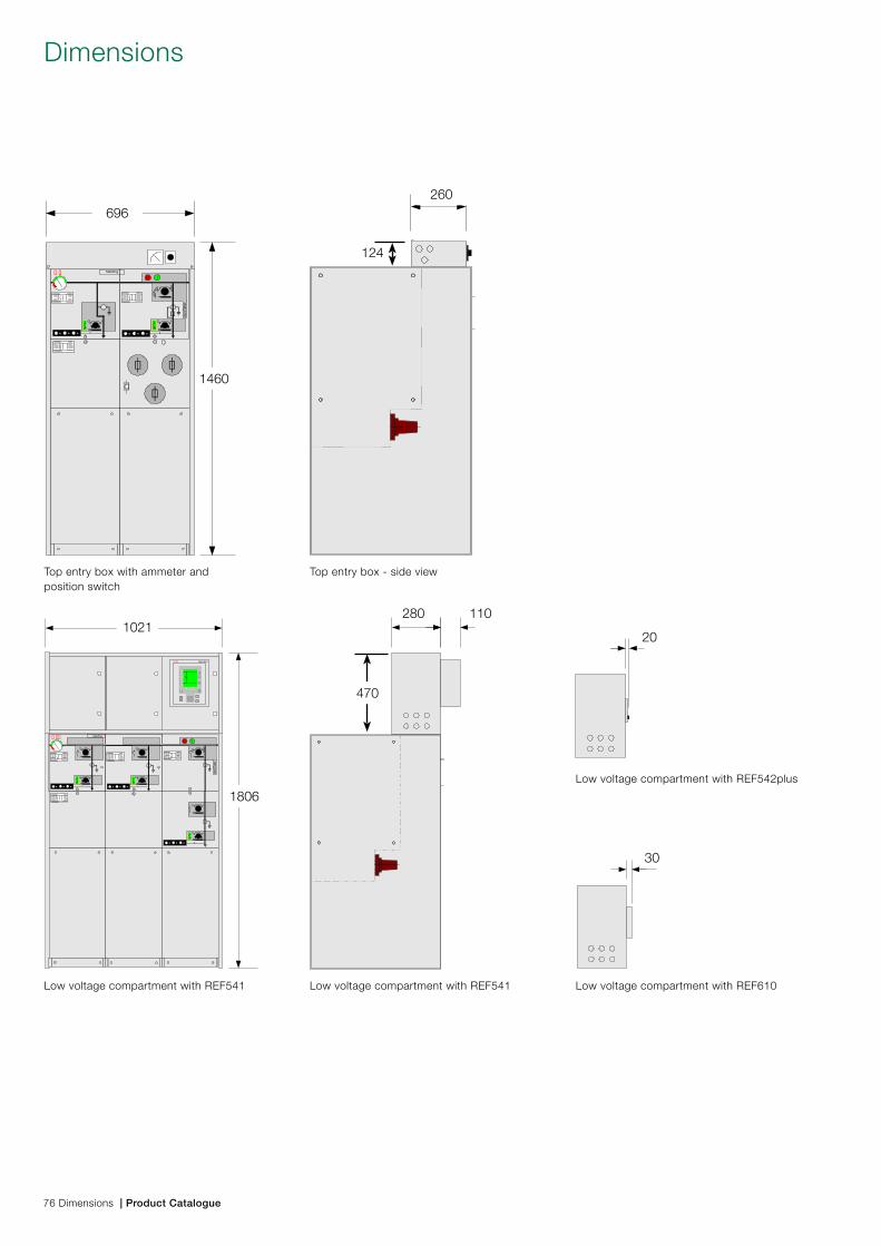
� � SafeRing
1460
696
124
260
� ��SafePlus
� �� REF541
1021
1806
110280
470
20
30
Low voltage compartment with REF541 Low voltage compartment with REF541
Low voltage compartment with REF542plus
Low voltage compartment with REF610
Dimensions
Top entry box with ammeter and position switch
Top entry box - side view
76 Dimensions | Product Catalogue
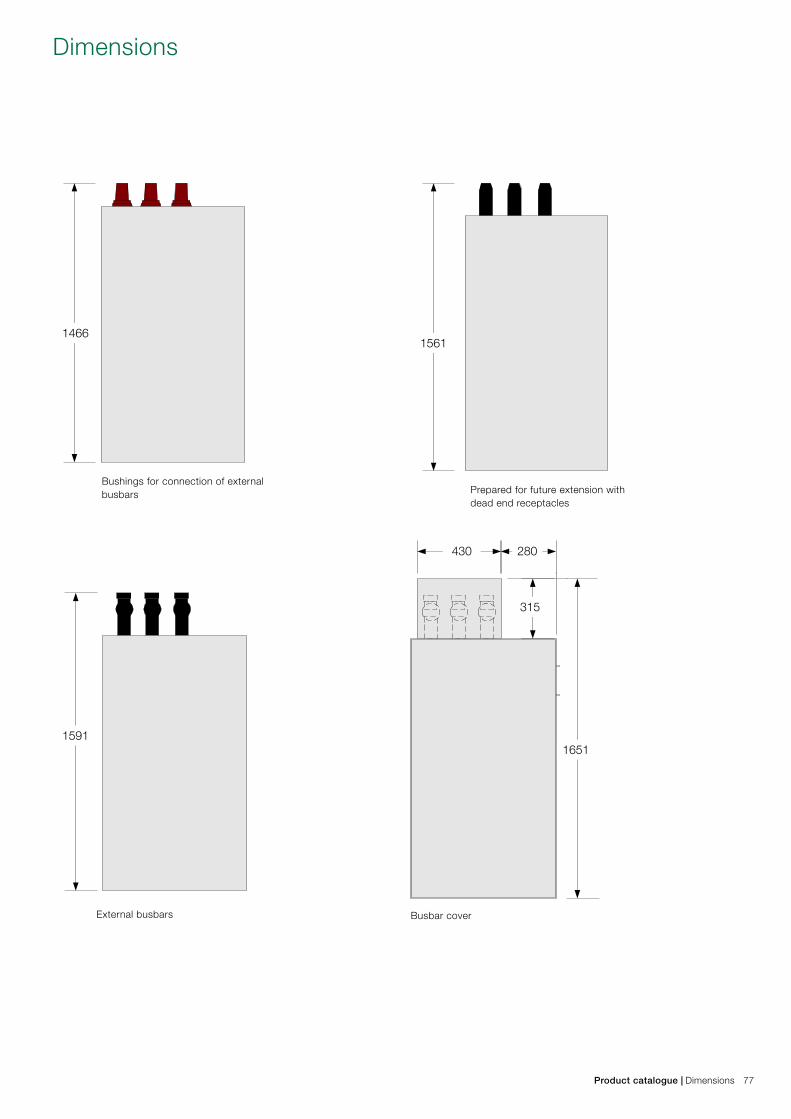
14661561
15911651
430 280
315
Product catalogue | Dimensions 77
Dimensions
External busbars Busbar cover
Bushings for connection of external busbars Prepared for future extension with
dead end receptacles
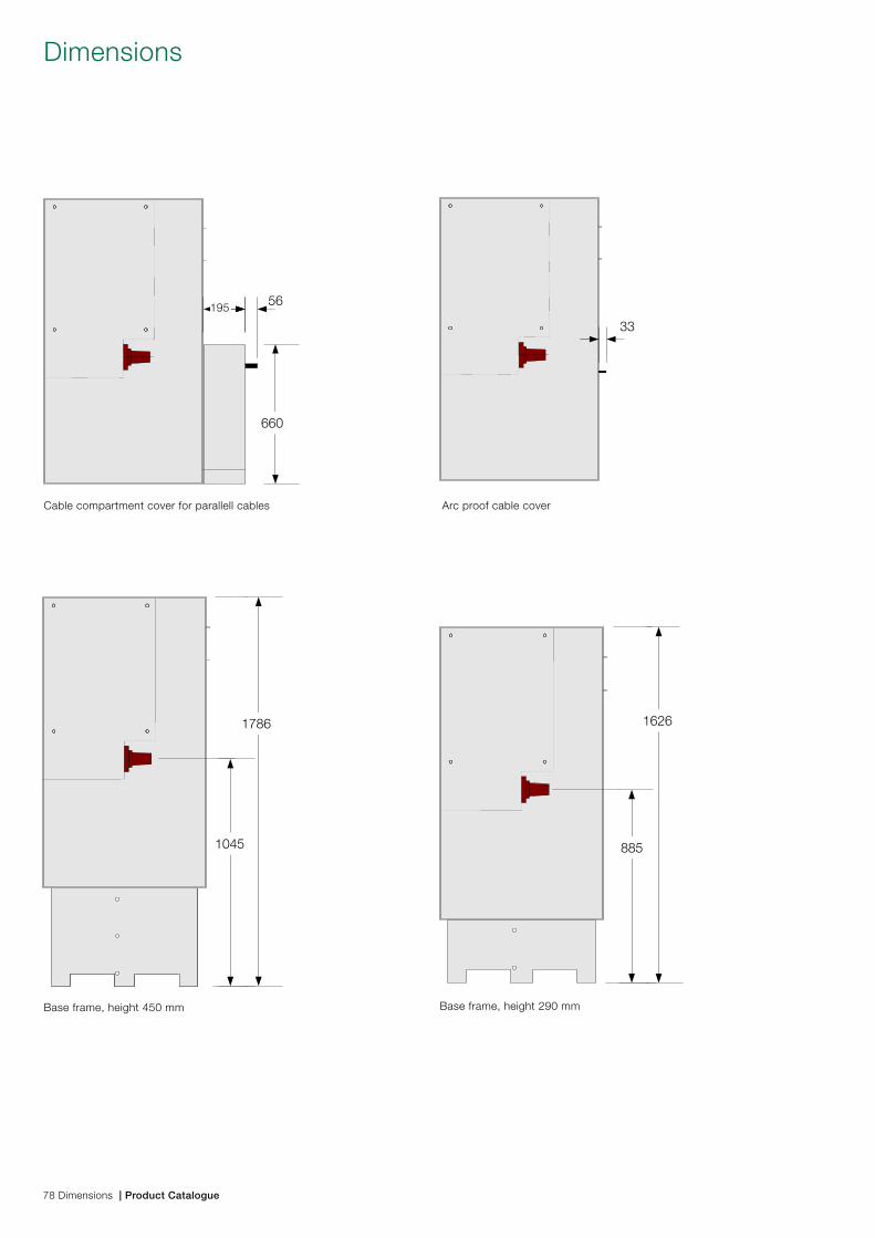
1786
1045
1626
885
33
56
660
195
Base frame, height 450 mm Base frame, height 290 mm
Dimensions
Cable compartment cover for parallell cables Arc proof cable cover
78 Dimensions | Product Catalogue
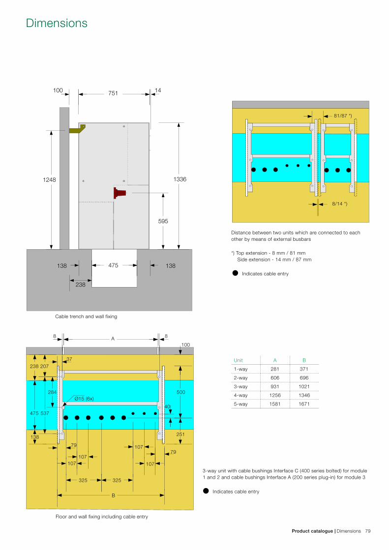
100 14751
595
475
238
138 138
1248 1336
238
325
B
A
325
251
79
37
8 8
79
138
207
107
107
107107
284
475 537
500
100
Ø15 (6x)
40
81/87 *)
8/14 *)
Product catalogue | Dimensions 79
Dimensions
Cable trench and wall fixing
Floor and wall fixing including cable entry
Distance between two units which are connected to each other by means of external busbars
3-way unit with cable bushings Interface C (400 series bolted) for module 1 and 2 and cable bushings Interface A (200 series plug-in) for module 3
• Indicates cable entry
*) Top extension - 8 mm / 81 mm Side extension - 14 mm / 87 mm
• Indicates cable entry
Unit A B
1-way 281 371
2-way 606 696
3-way 931 1021
4-way 1256 1346
5-way 1581 1671
IEC 62271-1 Common specifications for high-voltage switchgear and controlgear standards
IEC 62271-100 High-voltage switchgear and controlgear - Part 100: High-voltage alternating-current circuit-breakers
IEC 62271-102 High-voltage switchgear and controlgear - Part 102: Alternating current disconnectors and earthing switches
IEC 62271-105 High-voltage switchgear and controlgear - Part 105: Alternating current switch-fuse combinations
IEC 62271-200High-voltage switchgear and controlgear - Part 200: A.C. metal-enclosed switchgear and controlgear for rated voltages above
1 kV and up to and including 52 kV
IEC 60265-1 High-voltage switches- Part 1: Switches for rated voltages above 1 kV and less than 52 kV
IEC 60529 Degrees of protection provided by enclosures (IP code)
Codes and standardsSafeRing and SafePlus are manufactured and tested in accordance with the lates version of the below IEC regulations
Technical data
80 Technical data | Product Catalogue
Product catalogue | Technical data 81
SafeRing - Ring Main Unit, electrical data
1 Rated voltage Ur kV 12 15 17,5 24
2 Rated power frequency withstand voltage UdkV 28 38 38 50
- across disconnector kV 32 45 45 60
3 Rated lightning impulse withstand voltage UpkV 95 95 95 125
- across disconnector kV 110 110 110 145
4 Rated frequency fr Hz 50/60 50/60 50/60 50/60
5 Rated normal current (busbars) Ir A 630 630 630 630
6 Rated normal current (cable switch) Ir A 630 630 630 630
7 Rated normal current (switch-fuse-disconnector) Ir A 200 1) 200 1) 200 1) 200 1)
8 Rated normal current (vacuum circuit-breaker) Ir A 200 200 200 200
9 Rated short-time withstand current Ik kA 21 3) 21 3) 16 3) 16 3)
10 Rated duration of short-circuit tk s 3 3 3 3
11 Rated peak withstand current Ip kA 52,5 52,5 40 40
Making and breaking capacities C-module:12 Rated mainly active load breaking current I1 A 630 630 630 630
13 Number of operations for mainly active load breaking n 100 100 100 100
14 Rated distribution line closed-loop breaking current I2aA 630 630 630 630
15 Rated no-load transformer breaking current I3 A 20 20 20 20
16 Rated single capacitor bank breaking current I4cA 135 135 135 135
17 Rated earth fault breaking current I6aA 200 150 150 150
18 Rated cable- and line-charging breaking current under
earth fault conditions I6b A 115 87 87 8719 Rated short-circuit making current Ima
kA 52,5 52,5 40 40
Making and breaking capacities F-module:20 Rated mainly active load breaking current I1 A 200 200 200 200
21 Number of operations for mainly active load breaking n 100 100 100 100
22 Rated no-load transformer breaking current I3 A 20 20 20 20
23 Rated making capacity 2) IsckA 21 21 16 16
24 Rated making capacity (downstream earthing switch) ImakA 12,5 12,5 12,5 12,5
25 Rated short-time current (downstream earthing switch) Ik kA 5 5 5 5
26 Rated duration of short-circuit tk s 1 1 1 1
Making and breaking capacities V-module:27 Rated mainly active load breaking current I1 A 200 200 200 200
28 Rated short-circuit breaking current IsckA 16 16 16 16
29 Rated cable-charging breaking current Ic A 31,5 31,5 31,5 31,5
30 Rated short-time current (earthing switch) Ik kA 16 16 16 16
31 Rated short-circuit making current (earthing switch) ImakA 40 40 40 40
32 Rated filling level for insulation PreMPa 0,04 0,04 0,04 0,04
Service conditions for indoor equipment according to
IEC 60694
Ambient temperature 4)
33 Maximum value °C +40 +40 +40 +40
34 Maximum value of 24 hours mean °C +35 +35 +35 +35
35 Minimum value °C -25 -25 -25 -25
36 Altitude for installation above sea level 5) m 1500 1500 1500 1500
37 Relative humidity max 95% max 95% max 95% max 95%
1) T-off fuse module: depending on the current rating of the fuse2) T-off fuse module: limited by high voltage fuse-links3) Valid with Interface C bushings (400 series bolted type) only4) Derating allows for higher maximum temperature5) For installation above 1500 m, reduced gas pressure is required
Technical data
SafePlus - Compact Switchgear, electrical data
1 Rated voltage UrkV 12 15 17,5 24
2 Rated power frequency withstand voltage UdkV 28 38 38 50
- across disconnector kV 32 45 45 60
3 Rated lightning impulse withstand voltage UpkV 95 95 95 125
- across disconnector kV 110 110 110 145
4 Rated frequency fr Hz 50/60 50/60 50/60 50/60
5 Rated normal current (busbars) Ir A 630 630 630 630
6 Rated normal current (external busbars) Ir A 1250 1250 1250 1250
7 Rated normal current (cable switch) Ir A 630 630 630 630
8 Rated normal current (switch-fuse-disconnector) Ir A 200 1) 200 1) 200 1) 200 1)
9 Rated normal current (vacuum circuit-breaker) Ir A 200 / 630 200 / 630 200 / 630 200 / 630
10 Rated short-time withstand current Ik kA 25 / 21 3) 21 3) 21 3) 21 3)
11 Rated duration of short-circuit tk s 1 / 3 3 3 3
12 Rated peak withstand current Ip kA 62,5 / 52,5 52,5 52,5 52,5
Making and breaking capacities C-module:13 Rated mainly active load breaking current I1 A 630 630 630 630
14 Number of operations for mainly active load breaking n 100 100 100 100
15 Rated distribution line closed-loop breaking current I2aA 630 630 630 630
16 Rated no-load transformer breaking current I3 A 20 20 20 20
17 Rated single capacitor bank breaking current I4cA 135 135 135 135
18 Rated earth fault breaking current I6aA 200 150 150 150
19Rated cable- and line-charging breaking current under
earth fault conditionsI6b
A 115 87 87 87
20 Rated short-circuit making current ImakA 62,5 52,5 50 50
Making and breaking capacities F-module:21 Rated mainly active load breaking current I1 A 200 200 200 200
22 Number of operations for mainly active load breaking n 100 100 100 100
23 Rated no-load transformer breaking current I3 A 20 20 20 20
24 Rated making capacity 2) IsckA 25 21 20 20
25 Rated making capacity (downstream earthing switch) ImakA 12,5 12,5 12,5 12,5
26 Rated short-time current (downstream earthing switch) Ik kA 5 5 5 5
27 Rated duration of short-circuit tk s 1 1 1 1
Making and breaking capacities V-module:28 Rated mainly active load breaking current I1 A 200 / 630 200 / 630 200 / 630 200 / 630
29 Rated short-circuit breaking current IsckA 21 21 16 16
30 Rated cable-charging breaking current Ic A 31,5 31,5 31,5 31,5
31 Rated short-time current (earthing switch) Ik kA 21 21 16 16
32 Rated short-circuit making current (earthing switch) ImakA 52,5 52,5 40 40
33 Rated filling level for insulation PreMPa 0,04 0,04 0,04 0,04
Service conditions for indoor equipment according to
IEC 60694
Ambient temperature 4)
34 Maximum value °C +40 +40 +40 +40
35 Maximum value of 24 hours mean °C +35 +35 +35 +35
36 Minimum value °C -25 -25 -25 -25
37 Altitude for installation above sea level 5) m 1500 1500 1500 1500
38 Relative humidity max 95% max 95% max 95% max 95%
1) T-off fuse module: depending on the current rating of the fuse2) T-off fuse module: limited by high voltage fuse-links3) Valid with Interface C bushings (400 series bolted type) only4) Derating allows for higher maximum temperature5) For installation above 1500 m, reduced gas pressure is required
Technical data
82 Technical data | Product Catalogue
Product catalogue | Technical data 83
General data, enclosure and dimensions
1 Type of ring main unit (RMU) and compact switchgear (CSG) Metal-enclosed switchgear and controlgear according to IEC 62271-200
2 Number of phases 3
3 Type-tested RMU and CSG Yes
4 Pressure test on equipment tank or containers 2.64 bar abs
5 Facility provided with pressure relief Yes
6 Insulating gas SF6
7 Nominal operating gas pressure 1.4 bar abs 20°C
8 Gas leakage rate / annum 0,1%
9 Expected operating lifetime 30 years
10 Faclilities provided for gas monitoring Yes, temperature compensated manometer can be delivered
11 Material used in tank construction Stainless steel sheet, 2,5 mm
12 Busbars 240 mm2 Cu
13 Earth bar (external) 100 mm2 Cu
14 Earth bar bolt dimension M10
Overall dimensions of the fully assembled RMU Height mm Depth mm Width mm
15 2-way unit 1336 765 696
16 3-way unit 1336 765 1021
17 4-way unit 1336 765 1346
CSG (2, 3 and 4 way units as RMU) with additional height for
optional low voltage compartment (470 mm)
18 1-way unit 1336 765 371
19 5-way unit 1336 765 1671
20 Distance between units when external extension is used 8 mm
21 Distance between units when side extension is used 14 mm
Weight table
Maximum weights for standard SafeRing
2-way DeV 300 kg 2-way DeF 300 kg
3-way CCV 450 kg 3-way CCF 450 kg
4-way CCCV 600 kg 4-way CCCF 600 kg
4-way CCVV 600 kg 4-way CCFF 600 kg
3-way CCC 450 kg
4-way CCCC 600 kg
SafePlus
Standard 1-way 150 kg
2-, 3- and 4-way as for SafeRing
5-way 750 kg
M - metering module 250 kg
Mt - metering tariff module
Technical data
Operations, degree of protection and colours
1 Means of switch operation separate handle
2 Means of fuse switch/circuit-breaker operation separate handle and push buttons
3 Rated operating sequence of circuit-breaker (V-module) O – 3 min – CO – 3 min – CO
4 Rated operating sequence of circuit-breaker (CB-module) O – 0,3 s – CO – 3 min – CO
5 Total opening time of circuit-breaker approx. 75 ms
6 Closing time of circuit-breaker approx. 40 – 60 ms
7 Mechanical operations of switch 1000 CO
8 Mechanical operations of earthing switch 1000 CO
9 Mechanical operations of circuit-breaker (V-module) 2000 CO
10 Mechanical operations of circuit-breaker (CB-module) 30000 CO
11 Principle switch-disconnector and earthing switch 3 position combined switch-disconnector and earthing switch
Load break switch:
12 Rated operations on short circuit current (class E3) 5
13 Rated operations mainly active load (class E3) 100
Degree of protection:
14 High voltage live parts, SF6 tank IP 67
15 Front cover mechanism IP 2XC
16 Cable covers IP 3X
17 Protection class of fuse compartment IP 67
Colours:
18 Front covers RAL 7035
19 Side and cable covers RAL 7035
Fuses, cable compartment
1 Standard fuse-link length 442 mm. Shorter fuse-links can be used with fuse adapter
2 Standard dimensions According to DIN 43625
3 Maximum size 12kV 125 A
4 Maximum size 24kV 63 A
Cable box for heat shrinkable termination:
5 Phase to phase clearance 107 mm
6 Phase to earth clearance 54,5 mm
7 Phase to earth over insulator surface (creepage) 120 mm
8 Type of cable termination adapters Elbow or T-connector
Technical data
84 Technical data | Product Catalogue
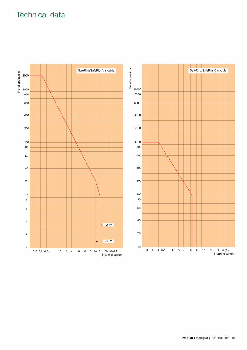
2000
1000
800
600
400
200
100
80
60
40
20
10
8
6
4
2
10,5 0,6 0,8 1 2 3 4 6 8 10 16 21 30 40 (kA)
Breaking current
No.
of o
pera
tions
SafeRing/SafePlus V module
12 kV
24 kV
10000
8000
6000
4000
2000
1000
800
600
400
200
100
80
60
40
20
105 6 8 2 3 4 6 8 2 3 4 (A)
Breaking current
No.
of o
pera
tions SafeRing/SafePlus C module
102 103
Product catalogue | Technical data 85
Technical data
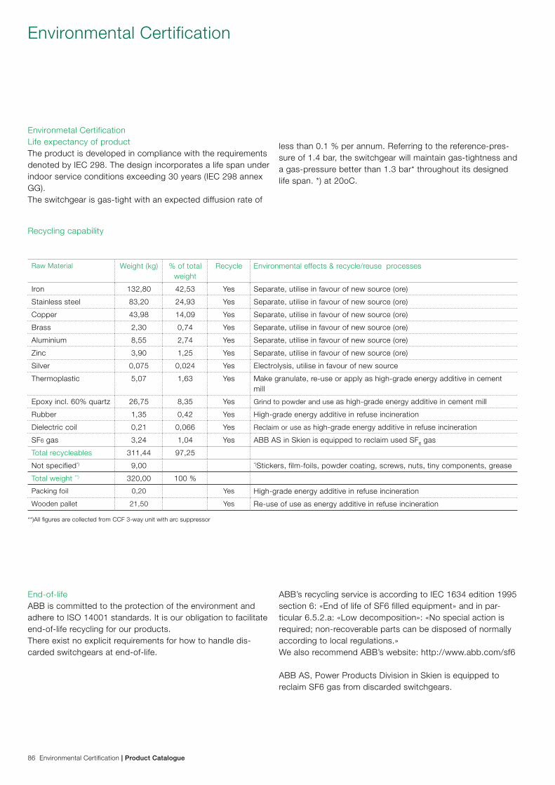
Environmetal CertificationLife expectancy of productThe product is developed in compliance with the requirements denoted by IEC 298. The design incorporates a life span under indoor service conditions exceeding 30 years (IEC 298 annex GG). The switchgear is gas-tight with an expected diffusion rate of
less than 0.1 % per annum. Referring to the reference-pres-sure of 1.4 bar, the switchgear will maintain gas-tightness and a gas-pressure better than 1.3 bar* throughout its designed life span. *) at 20oC.
Recycling capability
Raw Material Weight (kg) % of total weight
Recycle Environmental effects & recycle/reuse processes
Iron 132,80 42,53 Yes Separate, utilise in favour of new source (ore)
Stainless steel 83,20 24,93 Yes Separate, utilise in favour of new source (ore)
Copper 43,98 14,09 Yes Separate, utilise in favour of new source (ore)
Brass 2,30 0,74 Yes Separate, utilise in favour of new source (ore)
Aluminium 8,55 2,74 Yes Separate, utilise in favour of new source (ore)
Zinc 3,90 1,25 Yes Separate, utilise in favour of new source (ore)
Silver 0,075 0,024 Yes Electrolysis, utilise in favour of new source
Thermoplastic 5,07 1,63 Yes Make granulate, re-use or apply as high-grade energy additive in cement mill
Epoxy incl. 60% quartz 26,75 8,35 Yes Grind to powder and use as high-grade energy additive in cement mill
Rubber 1,35 0,42 Yes High-grade energy additive in refuse incineration
Dielectric coil 0,21 0,066 Yes Reclaim or use as high-grade energy additive in refuse incineration
SF6 gas 3,24 1,04 Yes ABB AS in Skien is equipped to reclaim used SF6 gas
Total recycleables 311,44 97,25
Not specified*) 9,00 *)Stickers, film-foils, powder coating, screws, nuts, tiny components, grease
Total weight **) 320,00 100 %
Packing foil 0,20 Yes High-grade energy additive in refuse incineration
Wooden pallet 21,50 Yes Re-use of use as energy additive in refuse incineration
End-of-lifeABB is committed to the protection of the environment and adhere to ISO 14001 standards. It is our obligation to facilitate end-of-life recycling for our products.There exist no explicit requirements for how to handle dis-carded switchgears at end-of-life.
ABB’s recycling service is according to IEC 1634 edition 1995 section 6: «End of life of SF6 filled equipment» and in par-ticular 6.5.2.a: «Low decomposition»: «No special action is required; non-recoverable parts can be disposed of normally according to local regulations.» We also recommend ABB’s website: http://www.abb.com/sf6
ABB AS, Power Products Division in Skien is equipped to reclaim SF6 gas from discarded switchgears.
**)All figures are collected from CCF 3-way unit with arc suppressor
Environmental Certification
86 Environmental Certification | Product Catalogue

1VD
D00
6104
GB
Ed
. M
ay 2
013
Contact us
ABB ASPower Products DivisionMedium VoltageP.O.Box 108, SentrumN-3701 Skien, NorwayPhone: +47 35 58 20 00Fax: +47 35 52 41 08www.abb.com
Text and illustrations are not binding. The right to make alterations is reserved
Copyright© 2013 ABBAll rights reserved