Strain Gages
119
CIVIL ENGINEERING MANUALS Instrumentation, gb.30.09.02 Strain Gauges: Theory, Instrumentation and Installation NSEL C&EE U ffiUC Second Edition Preparedby: Grzegoru Banasand Can Simsir Sponsored by: Newmark Structural Engineering Laboratory Department of Civil & Environ. Engineering College of Engineering University of Illinois at Urbana-Champaign Urbana. Illinois 61801 -2397 September,2002
-
Upload
damaris-arias -
Category
Documents
-
view
99 -
download
11
description
Información sobre strain gages
Transcript of Strain Gages
CIVIL ENGINEERING MANUALSInstrumentation, gb.30.09.02
Strain Gauges: Theory, Instrumentation andInstallation
NSELC&EEU ffiUC
Second Edition
Preparedby: Grzegoru Banas and Can Simsir
Sponsored by: Newmark Structural Engineering LaboratoryDepartment of Civil & Environ. Engineering
College of EngineeringUniversity of Illinois at Urbana-ChampaignUrbana. Illinois 61801 -2397
September,2002

NEWMARK STRUCTU RAL ENGINEERING LABORATORY

D
IR= o :
A
z
What is a sh'ain. gauec? It is a kansducer that allows the measurement of deformation(strain) in any material. Mechanical, optical, and electrical principles have been employed in theprocess of designing strain gauges. Types of electrical strain gauges include the resistance,capacitance, inductance, and the piezoelectric strain gauges. Due to their versatility, small sizeand weigfut, as well as high sensitivity to the measured static and dynamic strain, electricalresistance strain gauges have become the most popular in research and industrial applications. Inthis manual, only the electrical resistance strain gauges (strain gauges) will be discussed.
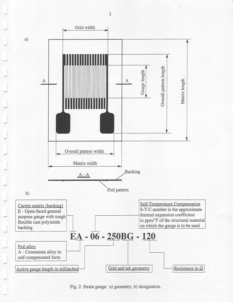
Figure 2a shows an example of a commonly used strain gauge. A photo-etched metal foilpattern is mounted on a plastic backing material (carrier). Constantan alloy is the oldest and themost widely used metal. Polyimide and giass-fiber reinforced epoxy-phenolic are commonlyused as backing materials. Each strain gauge has a specific designation that describes itscharacteristics (Figure 2b).
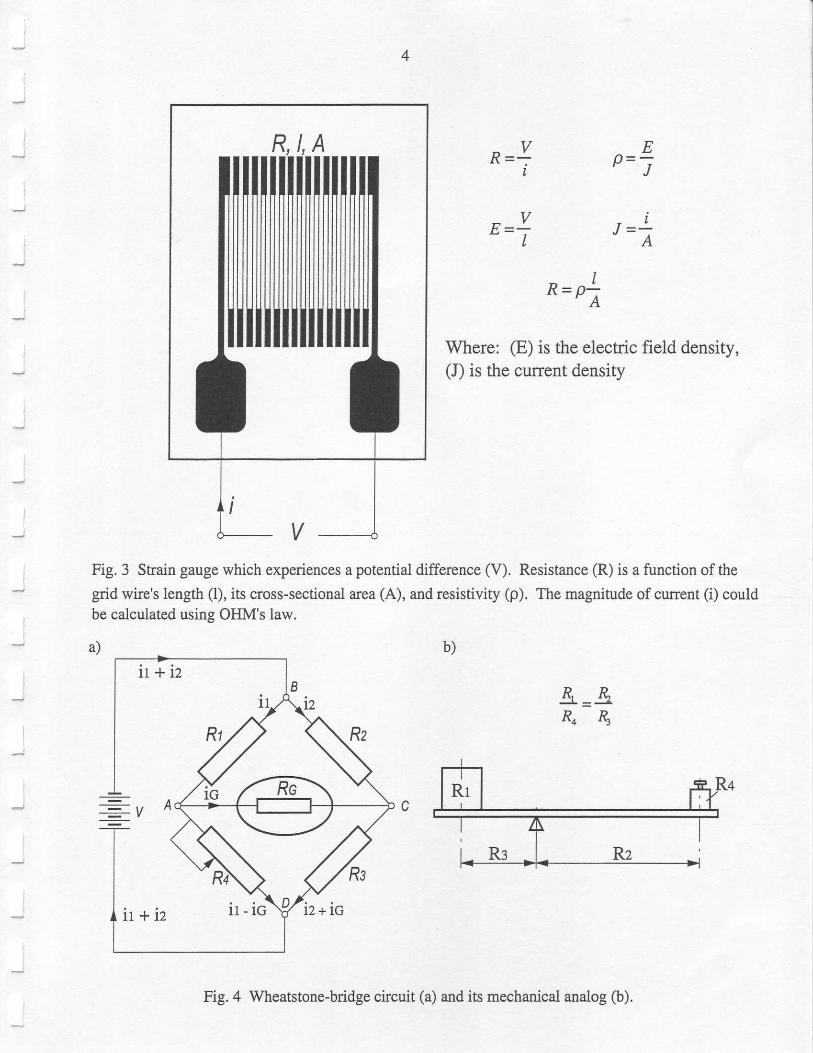
Florv does the strain gauge lvork? When the strain gauge is subjected to a potentialdifference ff) (Figure 3), current (i) is generated. The magnitude of cunent (i) depends upon theresistance (R) of the strain gauge:
Resistance (R) of the grid wire is a function of its resistivity (p), length (l), and cross-sectionalarea (A):
Assuming a constant potential difference (V), the magnitude of current (i) will vary with the gridwire's length (1) and its cross-sectional area (A). Therefore, if a shain gauge is bonded to amaterial experiencing surface deformation, current (i) will alter according to that deformationdue to changes in the length (l) and cross-sectional area (A) of the grid wire. When strainincreases, the wire length (l) increases, area (A) decreases, and for most materials the resistivity(p) increases, These. changes result in an increase in the resistance (R) of the wire. Thisrelationship between wire resistance and strain is linear at constant temperature, and it isexpressed by the gauge factor (K).
What is the eauge factor (K)? A strain gauge correlates two physicai quantities: changein resistance and change in strain. The dimensionless relationship between these two variables iscalled the gauge factor (K) of the sffain gauge and it is expressed mathematically as:
K-
where (R) and (1) represent, respectively, the initial resistance and initial length of the straingauge grrd wire, while (AR) and (A1) represent the small changes in resistance and length whichoccut as the gauge is strained along with the surface it is bonded to. Equation 5 assumes thatPoisson'srat iov=0.
%̂/t
Grid width
bo(.)
!9(!t
50(!)
ooo
a)
acking
Foil pattern
Carrier matrix (backing)E - Open-faced generalpurpose gauge with toughflexible cast polyimidebackine
Self-Temperature CompensationS-T-C number is the approximatethermal expansion coefficientin ppn/'F of the structuralon which the eause is to be used
Fig.2 Strain gauge: a) geometry, b) designation.
4
t ,
R=*I
t lp -J-
IR=pa
Where: (E) is the electric field density,(J) is the cunent density
Ee=j
J=!A
Fig. 3 Strain gauge which experiences a potential difference (V). Resistance fi.) is a function of thegrid wire's length (l), its cross-sectional area (A), and resistivity (p). The rnagnitude of cunent (i) could
&=&R4&
b)
be calculated using OHM's law.
Fig, 4 Wheatstone-bridge circuit (a) and its mechanical analog @).

)
What is th.e basic instnunentation? A Wheatstone-bridge circuit is used as a basicinskumentation for strain measurement; see Figure 4a. Ttrc magnitude of sfain is an equivalentof (AVl) ftom Equation 5 and is proportional to (ARtR). Since botl gauge factor (K) and
resistance @) are known, the strain (e) could be calculated by rewriting Equation 5:
N ^R/R
IK
In other words, the unit skain (e) equals to the unit change in resistance (AR.R) divided by thegauge factor (K). A change in resistance (AR) is the only unknown in Equation 6. Since themagnitude of (AR) is relatively very small (it is in the range of mO), the conventional ohmmetersare not recommended to use. They are not capable of measuring resistance with suffrcientprecision to detect such small differences. That is why the Wheatstone-bridge circuit iscommonly used.
Example: Strain gauge of resistance R = 120 f,) and gauge factor K = 2'0 is used forstrain measurement of specimen experiencing stess of S = 1,000 psi. Since modr.rlus of
elasticity (E) for steel is approximately 3O . 166 psi, tlen the corresponding unit strain is:
s 1"0005=r- : -::-:- -0.000033in/in.E 30.000.000
l r I
AR = Ri(? = 120 c2.0r 0.000033 = 0.0080 : 8 moI
It is apparent fiom these calculations that in order to determine AR, an instrument with theresolution of at least 0.001 O shall be used.
kr Figure 4a, assume that (R1) is an unknown resistance, (Rz) and (R:) are "tatio atms",
and (R4) is a resistance whose value is known precisely. When resistance values in this circuit
are such that no current flows through the galvanometer (i6 : 0), then the voltage across
galvanometer (V4 - 6) is also equal to zero (V,t - c:0). Since i6= 0, then:
Va-^ =Va-c or \& =k&
and
V"-o =Vc-o or iR4 =i24 6
Dividing Equation 7 by Equation 8, currents (ir) and (iz) could be eliminated:
+=+ fromwhich n =*n sR4R34
A mechanical analog of the wheatstone bridge is shown in Figure 4b. The unknownweight in this figure represents the unknow:r resistance (R1) and the small known weight the

6
resistor (R4). Similarly the respective moment arms of these weights from the firlcrum are theequivalent of @2) and (R3). From elementary statics it is obvious that when the lever is in astate of balance, then R1 . Ra = Rz . fu. Just as the lever system is termed "balanced" whenthere is no rnotion of the ends of the lever, so is the Wheatstone bridge "balanced" when there isno curent through the galvanometer. With ths resistor @4) whose value is known to a highdegree ofprecision and with means of measurilg the ratio R2/R3 precisely, tle resistance of (R1)can be determined very accurately with the Wheatstone-bridge circuit. In practice, the resistor(Rt) is an active strain gauge. If the skain gauge (R1), attached to the surface of the loadedspecimen, experiences any strain change, the change of its resistance (AR) will foliow.
The Wheatstone-bridge circuit has been primarily used to estimate (AR). This could bedone using three different approaches:
1. Bridge can be balanced by adjustirg the ratio (RzlR:), thus determining the exactresistance of the gauge that conesponds to zero load (ic = 0). The process of adjustingthe ratio (Rz/Rt) is equivalent to moving the ftilcrum of the lever system until theweights in Figure 4b just balance each other.
2. Bridge can also be balanced using an adjustable resistor (R4). This process of adjustingis equivalent to chariging the weiCht (It4) rurtil no motion of the lever is achieved.
3. hstead of re-balancing the bridge after loading the specimen, the galvanometerindication itself might be taken as a measure of strain. For small changes in theresistance (Rr), the galvanometer reading is proportional to the resistance change orstrain.
In practice, option number 3 is used in which the output from galvanometer is calibrated in strainunits.
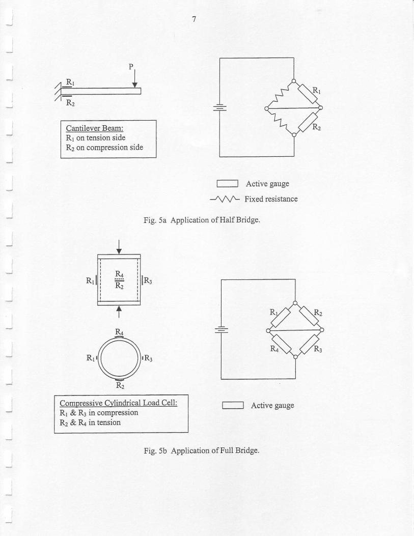
The Wheatstone bridge discussed above is caiied a Quarter bridge because only one ofthe four arms of the Wheatstone bridge has an active gauge (R1). Quarter bridge is used whensingie strains in a stress field are to be measured. Another b?e ofpractical Wheatstone bridge isthe Half bridge with only two active gauges on any two adjacent arms of the circuit, and twoother fixed resistances to complete the bridge. A typical application of Half bridge is on acantilever beam to determine bending shains by instrumenting the tension and compression sideseach with one active gauge (Figure 5a). The strains from the two gauges are equal but oppositein sign and thus help increase the sensitivity of the circuitry. In a Full bridge, ali fow arms haveactive gauges. This type of bridge can be used to good advantage in a ioad cell (Figure 5b). Ifthe gauges on two opposite arms of the circuit have equal shains, and the other two gauges haveequal strains that are opposite in sign to the frst two strains, then the sensitivity (the output ofthe bridge circuit) is increased by more than a factor oftwo.
More detailed information on practical Wheatstone-bridge circuits and their applications isavailable in Chapter 7 of Ref. 16. and in Ref, 19.
I
Cantilever Beam:R1 on tension sideR2 on compr€ssion side
Comnressive Cylindrical Load Cell:Rr && in compressionRz && in tension
l--l Active gauge
-Ann- Fixed resistance
Fig. 5a Application of Half Bridge.
l----l Active gauge
Fig. 5b Application of Full Bridge.

J
a)
Output cables
I
Fig. 6 Four channel, 2100 strain gauge conditioner and amplifier system (yellow box): a) pictureof-the 21fi) system, b) single channelsignal condifioner/amplifier, c) power supply, d) input
2Ao ocBO OD
GO Oe
HO Or
co 3oA
oO Oe
sO Oa
rO Os
HO OF
GO OE
BO OD
AO, OCI
FO OI r
EO OG
DO OB
"o4 oo
Channel I Channel2 Channel 3 Channel4 Power supply
c)
CIIANNEL
;ffi;DC---J | 11aa-
POWERE)ffERNAI-METER n-OO+UPOWERSIJPI{,Y OFF
breakout box.

10
Activestraingauge
r-oL--__>E
AH|'t
F
L-> E
ACF
(120 fl)(350 O)
Active strain(compressionor compensation) R = R l + R 2
Quater bridge: internal dummy. Halfbridge: prefened. Full bridge: strain gauges.
r--or_->E
B
Dummysnain gaugeor resistor
A
Quater bridge: extemal dummy.
Activestraingauge
A
cF
L-> E
Active strain(tension)
Active strain(compressionor compensation)
Half bridge: alternate.
Fig.7 Input breakout box's circuits.
Full bridge: ffansducer.
A
D
F
gauge
] .
].r* Input -

1 l
l igh ts (+and)shou ldbeext ingr r i s l red .The. ,BAI , -ANCE' ' res is to rcancor rec t fo ranapproximately +2,000 pe *tA*"! in 350 O quarter' half or firll bridge' With bridge inputs
other than 350 Q, rhe ;J;;; ,*c" will be reduced for lorver bridge resistance and
increased for higher onrrl roi t*uitprt, with a 120 o full bridge' the balance range is
reduced to under +700 pe' If the balance range proves inadequate for the gauges or
transducers in use, the tulanc" tesistor should be either replaced or shunted with an
additional one. The ratt"i option is used in the applications. Repeat this procedure for all
channels used' When ttittg * additional resistoi' make srue you know the resistor color
code available in Ref. 20.
6.The2100systemhasashrrntcalibrationbuiltintotheconditioner/amplifierwhichsimulatesa strail of 1,000 pe. Connect the voltmeter to an "output cable" conesponding to channel 1
(Figure 6a). Using the toggle swirch A-OFF-B (Figure 6b) for channel 1' a strain of 1'000
l.ri* U. ,i-ututJa eitheiln tension (position A) or compression (position B). Assuming
the maximum strain ro b;;ujoilJ;il"*n, ud,,*t th" giin using both ".GAN' screw and
knob i. such a way that iO viC o"tp* to""'pond' to G maximurn strain expected-' For
example: The maximum expected it'uin to be measured is 30'000 pe (3%' 3 ' 10-2)' In
spire of the resisrance "l;;-;;;;;,
berng used, when shunt bridge calibration is used to
simulate tension (toggle switch iln "A" position), the output voltage must be:
ljV o1.000 uel l = = U.JJJ , '" out ?o ooo rr_c
. / . I fa r rex temalshuntca l ib ra t ion isse lec ted , themagn i tudeofs imu la teds t ra incanbe
calculated:
tE*,= iL(&rt4)*ro'
where (Rr) is the precise effective resistance of arm shunted in (O)' (K') is the effective
gauge factor of strain gauge, and (R"uil is the calibration resistance in (Q)'
8. It is advisable to check both "AMP ZERO BAL' and "BALANCE" (points 4 and 5) on each
charrnel just before data ; tut ".
ri. "AMp zERo BAL" (point 4) should be checked
occasionallY on an extended test'
INSTALLATION
Srain gauge selection' Selection of strain gauges is the most important step in any stratn
measurement. The operating .[*r"i.rir,l* (teipeiature range, strain range, etc.) of strain
gauges are affected uy man! paramete$ (strail-sensitive alioy, backing materials (carriers),
gauge length, gauge pl$em' sef-tempe'atore compensation ttu-b"t' grid resistance' etc') which
eventually determ*. ro. u""u.u.y, ,"1'l"Lirity, *a cost of measurement. Ref. l provides a partial
* This requirement also comes from the limitation of our data loggilg systems' which are capable of storhg analog
sisrals at the *10 VDC level onlY'
l0
1I

t2
list of strain gauge manufacturers (copied from Ref. 16). Also, it is recommended to use the
selection proiedure presented in Ref. 1. Ifthe useris unsure of what gauge to choose, a'straingage application requirements' form (included at the end of Ref. 1) can be completed and
irt"tnJto either authors of this manual or the Micro-Measurements Group, who will then make
a selection based on the user descriptions of the test, the specimen and the gauge environment.
Temoerature compensation. The resistance of a strain gauge changes with temperature
variation This change in resistance is conholled by the coeffrcient of thermal expansion of the
alioy from which the strain gauge is fabricated. Also, in the case of any temperanrre variation,
the thermal expansion of the gauged material changes the resistance of the strain gauge. As a
consequence, errors in strail measurement occur. Two methods are available to minimize errors
due to temperature variation:
. Al application of a 'dummy' gauge which must be placed close enougb to the active
gurrg" -to
enswe that it will remain under all conditions at the same temperature as the
active gauge.
. Application of temperature-compensated strain gauges which must be used on materials
for which they have been compensated. The temperature compensation is controlled by a
choice of suitable constituents of the strain gauge alloy and suitable heat keatment during
its manufacture. This temperature compensation is not quite perfect, but over a
temperature range of about -20'c to +120'c the e or is small enough to be correctedfrom a graph of strain gauge error versus tempefature, supplied by the manufacturers of
the gauges.
Ref, 2 provides a detailed discussion on strain gauge temperature effects'
Surface preparation. Follow the procedure described in Ref. 3.
Strain gauee installation. The procedure of installing a strain gauge to_ the material
rutfu.. i. **ily associated with a type of adhesive used. Ref. 4 provides a list of
recommended adhesives for different strain gauge series (copied from Ref. 16). Ref.4 presents
also a procedure which could be used for most strain gauge applications in our laboratory. It is
recommended to follow this procedure.
Strain gauge soldering techniques. Soldering procedure is essential to the strain gauge
p".fo* t**ting wiris, soldering allon flux, soidering iron, etc. affect the quality of the
ioldered joints. The procedure presented in Ref. 5 is recommended for usage'
Use of bondable terminals. If bondable terminals are used between the mai;r leadwire
4O A" sr*utt jumper wires to the strain gauge, forces transmitted along the main leadwire
system can be prevented from damaging the strain gauge. The procedure presented in Ref' 6 is
recommended for application of bondable terminals'
Three wires versus two wires for quarter bridse circuits. It is recommended to use (three)
3 wires in the quarter bridge circuits for the followtng reasons:
. essential reduction ofthe initial imbalance ofthe bridge,

13
. better sensitivity,
. fundamental reduction of error that results from temperature changes in the lead wire system.
The procedure of using 3 wires presented in Ref. 7 is recommended for practice.
Protective coatine. Moisture is the most common cause of field installation failures. Itspresence usually results in 1ow eiectrical resistance to ground causing circulating currents,electrical noise, and desensitization of the measurement. Grid corrosion and intragrid conductivepaths can also form, causing negative or positive drift in output, depending on which cause ispredominant. Ref. I describes the most commonly used M-coat protectivs esnling kits. The M-coat A protective coating kit is recommended for usage, The M-coat F is recommended forstrain gauge applications on reinforcement bars in concrete. M-coat F protects the straingauge from moistue as well as the impact of aggregates in concrete.
Strain gauge for concrete. Expe.riments with concrete structures is quite common atNSEL, and strain gauge application for concrete requires a different and more chaliengingprocedure. Ref. 9 describes this procedwe, as well as provides installation and instrumentationtips for'embedment strain gauge' specially designed for use in concrete structures.
Noise control in measurements. Electrical noise in strain measurements is due toelectrostatic and electromagnetic fields in the strain gauge environment. Gauge selection, wiringtechnique, handling excess leadwires and cables can play an important role in controlling thisnoise. Ref. 10 provides information on detecting and reducing electrical noise in measurements.
Weldable strain gauges. These rugged and stable gauges are better suited for applicationsin severe environments, such as shoclg vibration, steam, saltwatff, extreme temperatures, etc.The installation of weldable strain gauges requires capacitive discharge spot-welding equipment.Spot-welding ofthe gauge to the specimen eliminates the need for all bonding materials, requiresminimal surface preparation and reduces installation time. Ref. 11 describes a few of theweldable strain gauges, and a portable strain gauge welding unit. Also provided is a selectionchart for weldable strain gauges courtesy of Ailtech, Inc. (copied from Ref. 16).
RIFERENCES
Ref. 1 Strain Gage Selection, Criteria, Procedures, Recommendations, Measurements Group,TECH NOTE, TN-505-3 (included).
Ref. 2 Strain Gage Thermal Output and Gage Factor Variation with Temperature,Measurements Group, TECH NOTE, TN-504-1 (included).
Ref. 3 Surface Preparation for Stmin Gage Bonding, Measurements Group, InstnrctionBulletin B- 129-7 (included).
Ref. 4 Strain Gage krstallations with M-Bond 200 Adhesive, Measurements Group,Instruction Bulletin B-127 -13 (includeO.

t4
Ref. 5 Shain Gage Soldering Techniques, Measurements Group, TECH TIP' TT-609(included).
Ref. 6 The Proper Use of Bondable Temrinals in Strain Gage Applications, MeasurementsGroup, TECH TIP, TT-603 (included).
Ref.7 The Three-Wire Quarter-Bridge Circuit, Measurements Group, TECH TIP, TT-612(included).
Ref. 8 M-Coat A protective coating kit. M-Coat F Application Iastructions, MeasurementsGroup, Instruction Bulletin B- 1 34-4 (included).
Ref. 9 Strain Gage Installations for Concrete Stnrcfiues, Measurements Group, TECH TIP,TT-611 (included). Embedment Strain Gage, EGP-Series, Measurements Group,Bulletin 321 (included).
Ref. 10 Noise Contol in Strain Gage Measurements, Measurements Group, TECH NOTE, TN-501-2 (included).
Ref. 11 An Introduction to... Micro-Measurements Shain Gages, Special Sensors, InstallationAccessories, Bulletin SFC-800-3 (partly included).
Ref. 12 2100 SYSTEM, Strain Gage Conditioner and Amplifier System, Measurements Group,Instn rction Manual (included).
Ref. i3 Ramsay, D. C. Principles of Engineering Instrumentation, published by Halsted Press,1996.
Ref. 14 Perry, C. C. and Lissner, H. R. The Strain Gage Prirner, published by McGraw-HillBook Cornpany, 1955.
_ Ref. 15 Dally, J. W. and Riley, W. F. Experimental Stress Analysis, published by McGraw-Hill Book Company, 1965.
Ref. 16 Ha:ris, H. G. and Sabnis, G. M. Structural Modeling and Experimentai Techniques,Second Edition, 1999.
Ref. 17 http://www.vishay.com./brands/measurements group
Ref. 1 8 http://www.cee.uiuc.edu/classes/cee398kuc
Ref. 19 http://www.me.osu.edu/me82/LeamindStrain/strain.html
Ref. 20 http://kelim.jct.ac.iVelectronics/webprogs/resistor/resistor.html

Reference 1

Table 7,2 Partial List of Manutacturers of Different Types ot Instruments
Manufacturer Address Types of Accessories
J
Insa.on Corp.
JP Technologies, Inc.
A.L. DesiSn, Inc.
BLH Electroflics, lnc.
Eaton Corp
l4l I Milirary Rd-8uffalo, NY 14217-1395tel: (7l6) 875-6240faxr (?16) 895-240475 Shawmu( Rd.Canton, MA 02021rer: (617) E2l -2000fax: (617) 828-145 |l?28 Maplelawn Rd.PO. Box 1089T!oy, MI 48099rel: (810) 643-0220fax: (810) 643-0259100 Royall St.Canton, MA 02021rer: (6 r7) 828-250042 nonh Benson Ave.PO. Box I168Uplnnd, CA 91786rel: (714) 946-t000fa( (7 14) 946-626'72048 Bunn€ll Rd.warringrcn, PA 189?6tel: (215) 343-041|faxj (215) 343-7388Div. of ffK Fluid Prod. croup3624 W Lake Ave-Glenvieq IL 60025rcr: (84?) 657-5300P.O . Box 27771Raleigh, NC 276i Itcl: (919) 36s-3800telr (919) 365-3945www.me:Irurcmen$group,comBox 24012Minnespolis. MN 55424tel: (612) 937-4000fax: (612) 937451565(14 Eridgc Poinr R(|.Ausrio, TX 78730-5039tel: (512) ?94-0100far: (512)794-841I
An OMEGA Tcchnologics Co.PO. Box 2721Stamford, CT 06906tcl: (203) 359-t660tax: (203) 3s9-78073425 Wald€n Ave.Dcpew, NY 14043tel: (7 I 6) 684-000 I900 Libeny SLOmve Ciry, PA 16127rel: (412) 458-96r0PO. Box 338Rr. 83Ellington. CT 06029rcl: (860) 872-8371tcl: (800) 828-39€'4fax: (860) 872421 |Essbn Rd.PO. Box 429Wallorv Crov€, PA 19090-0429rcl: (215) 675-7100fir: (2 I 5) 44 | -0899
SensoN, tmnsduc€rs. andinstrumcnution.
Strain gages, lccessodes,
Lord c€lh
Testing machines and load
Strain gages and accassories
Annealing fumrces
Stress coats of ditrcr€nt
All types of strain gagesand relarcd acccssoriesfor strain reading; daraacquisition systems
Servo-controlled loading
Dxtr arquisirion syst{Irs
St.ai! gages, load cclls, andall related acc€ssories forreading. sBain, prcssure.and force
Qu&rtz transducers tbrqua||(y m€asuremcnt
Electro mechlnical (eslingsystcms
Linear displacemcnr
ltsting machincs lnd
Lucifer
Magnaflur Corp.
Micro-Measur€menB D,VMcaluements Grcup. Inc,
MTS Sysrefis Corp.
National InsrumenG
OMECA Engincering, Inc.
rcB Piezoronics. lnc.
SATEC Systems, Inc.
TRANS-TEK
Tini0s-Olsen TesdnsMachine Co.. Inc.

Table 7.3 Standard Shain Gage Serles Selection Chart (Courtesy Measuremenls croup, Inc.)
GageSed€s
Fatlgue LileStrain Level No. ofDescriptlon and
Primary AppllcaiionTelnperature
RangeStrainRanEe In p€ cycles
SA
EP
ED
wt)
SD
Et
S K
r20001r800t 1500
r I 800r 1500
r1000
1250012200
13000r2500!220012500t22001t800
t220012000
105106
l 0 r
l0 i1otu
1 0 0l 0 ?
r0:r 06l0 '
t 06r0?
t0b
l0r
105l0rr03l0or0?1 U '
l0ol0r
t 0 6
1 0 7
I {.J0t0'
t l .59o
l l . 5 9 e
t l .SVa
Conslanun foil in combination with a rough, ffexible,polyimide backing; wide .ange of options available,primarily inbnded for generalpurpose static anddvnarnic stress analysis: no! recommended for higheslaccuracy ransducers
Universal g6n"o1-Or*ose strain gages: constantan gridcompletely encapsulaied io polyimide, wi!h large, ruggedcopper-coated tabs: primarily used for general-purposestatjc rnd dynamic stress analysis; 'C'-feature gages arcspeciaU!, hithlighted th.oughout the gage lisrings
Open-faced constantan foil Sages with a thin, laminated.polyimide-film backjng; p.imarily recommended for usein precision rmnsdlcers. the N2A Series is charscrerizedbf lo$, and repeatable creep perforrnance; also aecommendedlbr sress analysis applicalions employing la€e gag€patEms. wherc rhe especially nai marix eases gageinsral lat ion
Fully encapsulated constanEn gages with hjgh-enduranceIcrd rvires; useful over wider temperature ranges and innrorc ertreme envifonments than EA series: option wvailable on some paftems, but .esrricts fatigue life ro
Fully encapsulaled constaotan gages with solder dotslSame matrix as WA Series; sarne uses as WA Seriesbur deat€d somewhat in maximum tempcErure anoopcratlng environment because of solder dots
Specially annealed consrantan foil wirh tough, high-elongadonpolyimide backing; used prirnarily for measuremenrs oflargc posFyieid strains; availabl€ wi(lj Options E, L,:rnd LE (may .estrict elongation capability)
lsoclasdc foil in combinarion with lough, nexible polyimidelilm: high gate factor and extended fadgue life excellenttbr dynamic measuremenG; not nornally used i|l slaticmeasurcments due to very high thermal output characlerisdcs
Fully €ncapsulared isoelas!ic gages with high-cndurancelecd wires: used in wide-range dynamic skain measuremenlpplications in severc environments
Equivllent lo WD Series, bul with solder dots instead of
K-lllor lbil in combioarion wirh a rcugh, Rexible polyimidcbrcung; primarily used where a combin rion of hiSherBfld resistances, slability at eievated temp€rature, lrndgrearesr backing flexibiliry is required
Fully cncapsulaled K-alloy gages \rirh high-endurancelead wires; widest lemperature range and most exuemecnvironmental capability of any general-purpose gagewheo self-temperatu.c compensation is required; OplionW available on some parrErns, but restdcts borh fariguelit! and maxirium operaring lompemture
l_rully encapsulated K-alloy gages with solder dors: sameuses ia WK Series, but d€rated in maximum lemp€raluieund operating environmen! because of solder dots-269' ro +260"C
K-ulluy fbil laminaled !o 0.025-mm-!hick, high-performancepolyimide bacung, with a laminared polyimide overlaylullr encapsuladng the grid atld solder rabs; providedrv'lh largc solder pads for ease of lead wire arrachment
Normal:-75 to +175'C
Sp€cial or shoat-term:-195 ro +205'C
Normal:-75 to +175'C
Stacked rosettes limired to+65'C
Normal staticlransouc€r servrcc:-75 1o +95oC
Normal:-75 to 205'C
Special or sho(-term:-195 ro +260"C
Normal:-?5 10 +205"C
Special or short-te.rn:-195 ro +230'C
-75" io +205'C
Dynamic:-195 to +205"C
Dynamic:-195 to +260oC
Dynamic:-195 (o +205'C
Normal:-195 ro + I75"C
Spccial or short-Lcnn:-269 rc +205oC
Normal:-269 !o +290"C
Special or short-term:-269 to +400'C
Normal:-269 lo +230'C
Special or short-refin:
Noflnal:-?5 to + 120'C
Speciirl or sho(-rcftn:-185 to +150'C
l37o lor gagc lengthsunder 3.2 mm
t57o for 3.2 mm
1-lE fof Eage lengthsunder 3.2 mm
!5Eo tor 3 .2 mmand over
!34c
r r800r15001l 200
115001r 500
!170011500
!29c
ll09o for gage lengthsundcr 3.2 mm
t20% fbr 3.2 mm
t2?o -
nonlinear a( sllainlevels over i0.570
Xl.5Vo -
nonlinear at strainlevels over i0.5%
l t . 5 %
l l . 5 i o
!220012000
i 1800ir500
' Fadgue life amproved using low-moduius sold€f.' EP g.rges sho$ zero shift under high-cycjic sfains.

t Strain GageSelection
Strain Gage SelectionCriteri a, P roced u res, Reco m men d ati o ns
1.0 Introduction
The initial step in preparing for any strain gage installation is
the selection of the apPropriate gage for the task. It might at first
appear that gage selection is a simple exercise, of no great con-
sequence to the stress analyst; but quite the opposite is true.
Careful, rational selection of gage characteristics and parame-
ters caa be very important irl: optimizing the gage performance
for specified envtonmental and operating conditions, obtaining
accurate and reliable strain measurements, contibutilg to the
ease of installation, and minimizing the totdl cost of the gage
installation.
The installation and operating characteristics of a strain gage
are affected by the following parameters, which are selectable
in varying degrees:
, l
The cost of the strain gage itself is not ordinarily a prime
consideration in gage selection, since the sigdficant econornicmeasure is the total cost of the complete installation, of which
the gage cost is usually but a small fraction. In many cases, the
selection ofa gage series or optional feature which ilcreases thegage cost serves to decrease the total installation cost.
It must be appreciated that the Process of gage selection gen'
erally involves compromises. This is because parameter choic-es which tend to satisfy one of the constraints or requiremeltsmay work against satisfying others. For example, in the case ofa small-radius fillet, where the space available for gage installa-tion is very limited, and the strain gradient extemely high, oneof the shortest available gages might be the obvious choice. Atthe same time, however, gages shorter than about 0.125 in(3 mm) Ne geterally characterized by lower maximum elonga-tion, reduced fatigue life, less stable behavior, and greater
installation difficulty. Another situation which often influencesgage selection. and leads to compromise, is the stock ofgages athand for day+o-day stmin measurements. While compromisesare almost always necessary, the s[ess analyst should be fullyaware of the effects of such compromises on meeting therequirements of the gage installation. This understanding is
necessary to make the best overall comPromise for any Particu-lar set of circumstances, and to judge the effects of that com-promise on the accuracy and validity of the test data.
The sftain gage selection criteria considered here rclate pri-
marily to stEss analysis applications. The selection criteda for
strain gages used on transducer spring elements, while similar
in many respeds to the considerations Presented herc, may vary
significantl l from apPlication to aPplication and should be
treated accordingly. The Measurements Grcup's Transducer
Applications Department can assist in this selection.
. gage panem
Basically, the gage selection Process consists of determining
the particular available combination of parameters which is
most compatible with the envircnmental and other opemting
conditians, ard at the same time best satisfies the installation
and operating constraints. These constraints are generally
expressed in the form of requirements such as:
. test dumtion
. cyclic endurance
. ease of installation
. environment
. strain-sensitivealloy
. backing materials(carrier)
. gage length
r accuracy. stability. temperarure. elongation
. self-temperature-comPensation number
. gdd resistance
. options
ocopyright Measurements Group, Inc., 1989
MEASUREMENTSGBOUP
t)
2.0 Gage Selection Parameters
2.1 Strain-Sensing AIloYs
The principal comPonent which determines the oPerating
characteristics of a sbain gage is the strain-sensitive alloy used
in the foil grid. However, the alloy is not in every case an inde-
peodently selectable Parameter. This is because each Micro-
Measurements strain gage series (identified by the first two, or
three, lette$ in the alphanumeric gage designation - see dia-
glam on page 1l) is designed as a comPlete system. That system
is comprised of a particular foil and backing combinatioo, and
usually incorporates additional gage construction featues (such
as encapsulation, integral leadwires, or solder dots) specific to
the series in question.
Micro-Measurements suPplies a variety of strain gage alloys
as follows (with their respective letter designations):
A: Constantan in self-temperature-compensated form.
P: Annealedconstantan.
D: Isoelastic.
K: Nickel-chromium alloy, a modified Karma in
self-temperature-compensated form.
2.1.1 Constantan AlloY
Of all modem strain gage alloys, coNtantan is the oldest,and still the most widely used. This situation reflects the factthat comtantan has the best overall combination of properties
needed for many strain gage applications. This alloy has, forexample, an adequately high s[ain sensitivity, or gage factor,which is relatively insensitive to stmin level and temperature.
lts resistivity is high enough to achieve suilable resistance val-
ues in even very small gdds, and its temperature coefhcient ofrcsistance is not excessive. In addition, constantan is character-ized by good fatigue life and relatively high elongation capabil-ity. It must be noted, however, that constantan tends to exhibit acontinuous ddft at tempemtures above +150'F (+65"C)i ardthis characteristic should be taken into account when zero sta-bility ofthe strain gage is critical over a period ofhours or days.
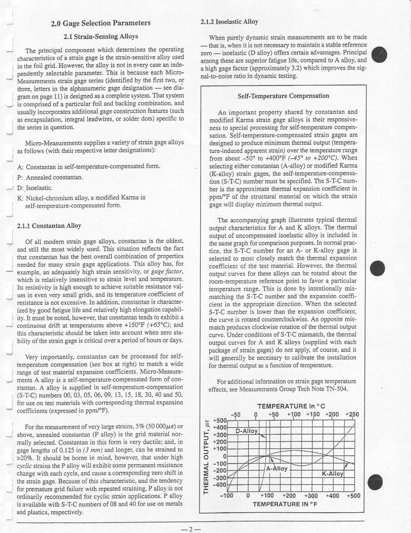
Very importantly, constaotan can be processed for self-temperature compensation (see box at righD to match a widerange of test material expansion coefficients. Micro-Measure-ments A alloy is a self-temPerature-compensated form of con-stantan, A alloy is supplied in self-tempemture-compensation(S-T-C) numbers 00 ,03 ,05 ,06 ,09 , 13 , 15 , 18 ,30 ,40 and 50 ,for use on test materials with conesponding thermal expansiorlcoefficients (expressed in ppn/'F).
For the measurement of very large strains, 5% (50 000t 8) orabove, annealed constantan (P alloy) is the grid material nor-mally selected. Constantan in this form is very ductilel and, ingage lengths of 0.125 in (3 rnn) and longer, can be strained to>207o. It should be borne in mind, however, that under highc)c&c stnins the P alloy will exhibit some permanent resistancechange with each cycle, and cause a corresponding zero shift inthe strain gage. Because of this chancte stic, and the tendencyfor premature grid failure with repeated stlaining, P alloy is notordinarily recommended for cyclic strain applications. P alloyis ayailable with S-T-C numbers of 08 and 40 for use on metalsand plastics, respectively.
2.1,2 Isoelastic Alloy
When purely dynamic strain measurements are to be made- that is, when it is not necessary to maintain a stable refercncezero - isoelastic (D alloy) offers certain adYantages. PrinciPalamong these are superior fatigue life, compared to A alloy, anda high gage factor (approximately 3.2) which improves the sig-nal-to-noise latio in dynamic testing.
oSelf-Temperature ComPensation
An important proPerty shared by constantan andmodified Karma strain gage alloys is their resPonsive-ness to special processing for self-temperaturc compen-sation. Self-temperature-compensated strain gages aredesigned to produce minimum thermal output (temPera-
ture-induced apparent strain) over the temperature rangefrom about -50' to +400"F (45' to +200"C). Wher'selecting either constantan (A-alloy) or modified Karma(K-alloy) strain gages, the self-temperature-compensa-tion (S-T-C) number must be specified. The S-T-C num-ber is the approximate thermal expansion coefficient inppr/'F of the structural material on which the straingage will display minimum thermal output.
The accompanying gaph illusaates typical thermaloutput characteristics for A and K alloys. The thermaloutput of uncompensated isoelastic alloy is included inthe same graph for comparison purposes. In normal prac-tice, the S-T-C number for an A- or K-alloy gage isselected to most closely match the thermal exPansioncoefficieflt of the test material. However, the thermaloutput curves for these alloys can be lotated about theroom-temperature reference point to favor a particulartempemture range. This is done by intentionally mis-rnatching the S-T-C number and the exPansion coeffi-cient in the appropriate direction. When the selectedS-T-C number is lower than the expansion coefficient,the curve is rotated counterclockwise. An opposite mis-match produces clockwise rotation of the thermal outputcurve. Under conditions of S-T-C mismatch, the thermaloutput cunes for A and K alloys (supplied with eachpackage of strain gages) do not apply, of course, and itwill generally be necessary to calibrate the installationfor thermal output as a function of tempemture.
For additional informatio[ orl sEain gage temperatureeffects, see Measurements Group Tech Note TN-504.
F
F
oJ
=UJ
F
TEMPERATURE in oC
TEMPERATURE IN 'F
- 2 -

,
D alloy is not subject to self-temperature compensation.Moreover, as shown in the graph (see box), its thermal outPut is
so high labout 80pe]"F (145 p,efc)l that this alloy is not nor'mally usable for static strain measurements. There are times,however, when D alloy finds application in special-purposetransducers where a high output is needed, and where a fuIl-bridge arangement can be used to achieve reasolable tempera-ture compensation with.in the ckcuit.
Other properties of D alloy should also be noted when con-sidering the selection of this grid material. It is, for instance,magnetorcsistive; and its response to strain is somewhat nonlin-ear, becoming significandy so at stmins beyond t5000pre.
2.1.3 Karma Alloy
Modified Karma, or K alloy, with its wide areas of applica-tion, represents an importaot member in the family of straingage alloys. This a1loy is characterized by good fatigue life andexcellent stability: and is the prefened choice for accunte stat-ic strain measurements over long periods of time (months oryea$) at room temperanrre, or Iesser periods at elevated tem-peratue. It is recommended for extended static sfain measure-ments over the temperature range from -452" to +500'F (-269"
to +260'C). For short periods, encapsulated K-alloy straingages can be exposed to tempelatures as high as +750'F(+400'C). An inert atmosphere will improve stability andextend the useful gage life at high temperatures.
Among its other advantages, K alloy offers a much flatterthermal output curye than A alloy, and thus permits rnore accu-rate correction for thermal output errors at temperature ex-tremes. Like constantan, K alloy can be self-temPeraturc-com-pensated for use on materials with different thermal expansioncoeffrcients. The available S-T-C numbers in K alloy are limit-ed, however, to the followirg: 00, 03, 05, 06, 09, 13, and 15.K alloy is the normal selection when a temperature-compensat-ed gage is requLed that has environmental capabilities and per-formance characteristics not attainable in A-alloy gages.
Due to the difficulty of soldering directly to K aUoy, theduplex copper feature, which was formerly offered as an option,is now standard on all Micro-Measurements ope[-faced straingages produced with K alloy. The duplex coPper feature is aprecisely formed copper soldedng pad (DP) or dot (DD),
depending on the available tab area. All K-alloy gages which donot have leads or solder dots are specif,red with DP or DD aspaft of the designation (in place of, or in addition to, the oPtionspecifier). The specific style of copper teatment will be advisedwhen the Customer Service Department is contacted. Open-faced K-alloy gages may also be ordered with solder dots.
2.2 Backins Materials
Conventional tbil strain gage construction involves a photo-etched metal foil ptLttern mouated on a plastic backing or carri-
: er The backing serves several important functions:
. provid€s a means for handling the tbil pattern during instal-
al . lation
Lf . or.r"n,, a readily bondable surface for adhering the gage to
the test specimen. provides electrical insulation between the metal foil and the
test object
Backing materials supplied on Micro-Measurements straingages are of two basic types: polyimide and glass-fiber-rein-forced epoxy-phenolic. As in the case of the strain-sensitivealloy, the backing is not completely an independently specifi-able pammeter. Cenain backing and alloy combinations, alongwith special construction features, are designed as systems, andgiven gage series designations. As a rcsult, when arriving at theoptimum gage type for a particular application, the process doesnot permit the a$irary combination of an alloy ard a backingmaterial, but requires the specification of an available gageseries. Micro-Measurements gage s€ries artd their ProPerties aredescribed in the following Section 2,3. Each series has its owncharacteristics and prefened areas of application; and selectionrecommendations are given in the table on page 5. The individ-ual backing materials are discussed here, as the alloys were inthe prcvious section, to aid in understanding the properties ofthe series in which the alloys and backirg materials occur
The Micro-Measurements polyimide E backing is a toughand extremely flexible carrier, and can be contoured readily tofit small radii. In additior, the high peel stength of the foil onthe polyimide backing makes polyimide-backed gages less sen-sitive to mechanical damage during installation. With its ease ofhandling and its suitability for use over the temperature rangefrom -320" to +350"F (-195'to +175"C), polyimide is an idealbacking material for general-purpose static and dynamic stessanalysis. This backing is capable of large eloogations, and canbe used to measure plastic strains ir excess of 20Vo. Polyimidebacking is a featurc of Micro-Measurcments EA-, CEA-, EP-,EK-, SzK-, N2A-, and ED-Series strain gages.
For outstanding performance oyer the widest range of tem-peratLrres, the glass-fi ber-reinforced epoxy-phenolic backingmaterial is the most suitabl€ choice. This backing can be usedfor static and dynamic strain measulement from -452' to+550'F (-269' to +290"C). In short-term applications, theupper temperature limit can be extended to as high as +750'F(+400'C). The maximum elongation of this carrier material islimited, however, to about 1 to 2%. Reinforced epoxy-phenolicbacking is employed on the following gage series: WA, lVK,SA. SK. WD. and SD.
2.3 Gage Series
As noted in Secfions 2.1 ar'd2.2,the strain-sensing alloy andbacking material are not subject to completely independentselection and arbitrary combination. lnstead, a selection mustbe made from among the available gage systems, ot serieJ,where each series generally incorporates special design or con-struction features, as well as a specific combination ofalloy andbacking material. For convenience in identifying the appropri-ate gage series to meet specified test requirements, the informa-tion on gage series performance and selection is presented here,in condensed tbrm, in rwo tables.
The table on the following page gives brief descriptions ofall general-purpose Micro-Measuremenls gage series - includ-ing in each case the alloy and backing combination and the prin-cipal construction features. This table defines the performanceof each series in terms of operating temperature rarlge, straiorange, and cyclic endurance as a function ofstain level. It mustbe noted, however, that the performance data arc nominal, a$dapply primarily to gages of 0.125 in (3 mm) or longer gageleneth.
- 3 -

Standard Strain Gage Series Selection Chart
r A ;:RTES
: . i .
DESCRIPTION AND PHIMARY APPLICATION..
TEMPEFATURE RANGEFATIGUE LIFE
Straln Ievelln pe
Numbetof Cycles
6o*t"nt"n foil in combination with a tough, fleJible'
folyimide backing. Wide range of options available'Fri inarily intended for general-purpose static anddynamic-stress analysis. Not recommended fgr highestaccuracv t€nsducers.
Normal: -100" to +350'F(-75' to +175"C)
Special or Short-Term:-320" to +4009F
(-195" to +205"C)
i3% lor gagelengths under
1lA in P.2 nn)i5% for 1/8 in
and over
r'180011500*240
1o:10"108
Universal aeneral'purpose strain gages Constantanorid comolelelv encapsu ated in po yimide' with iarge,iuooed coooer-coated tabs Primarily used fof general-ouiiose siatic and dynamic stress analysis 'c'-Feature
gages are specially highlighted throughout the gage list-ings oJ Catalog 500.
Normal: -100' to +350'F(-75" to +175"C)
Stacked rosettes limited to+150'F (+65'C)
!3'/" lot gagelengths under
118 i^ (3.2 nm)i5% for 1/8 in
and over
i 150011500
10:,1oo
'Fatigue liie imp.ovedusing low-modulus solder.
NZA
Normal StaticTransducef Service:
-100'to +200'F/-746 h LA6tal
!3"/.!1700a1500
Normal: -100" to+4OO'F(-75' to +205"C)
Special or Short-Terrn:-320' to +500'F
(-195'to +260"C)
12000a1800a1500
10"t06107
Fullv encapsulated constantan gages with solder dols.same matiix as WA Series. Same uses as WA Seriesbut defated somewhat in maximum temperature andoperating environment because of solder dots.
Normal: -100" to i4oo"F(-75" to +2o5ec)
Special or Short-Term:-320'to +450"F f-l95" to +230"C)
+1800!1500
WD
Soeciallv annealed constantan foil with tough, high-elon-qition potyirnid" backing. Used primarily for measure-ients of large post-yield strains. Availab'e with Opl onsE, L, and LE (day reslrict elongation capability).
-100'io +400'Ft-7cd t^ !rn6oC)
i10% for gagelengths unde.1l8 n (3.2 nm)!20"/" tot 1/8 in
ano ovea
!1000 10-
EP gages show zero shiftunder high-cyclic sirains.
lsoelastic ioil in combination with tough, l lexible poly-imide film. High gage factor and extended fatigue lifeexcellenlfor dvnamic measurements. Not no.mally usedin slatic meas;rements due to very high thermal-outputcharacteristics.
Dynamic:-320" to +400"F
(-1ss" to +205'C)
!2'hNonlinear atstrain levelsover r0.5%
12500\2200
10"107
Fully encapsulated isoelastic gages wilh high-endur-ance leadwires. Used in wide-range dynamic strainmeasurement aoplications in severe environments.
Dynamic:-320' to +500'F
(-195' to +260'C)
t1.57o - non-linear at strain
levels over i0.5%
!30001250012200
10"107108
Equivalent to WD Series, but with solder dots instead ofleadwires.
Dynamic:-320' lo +400'F (-195" to +205'C)
i 1 . 5%See above note
12500!2200
10"
WK
K-alloy foil in combination with a tough, f lexible poly-imide'backing. Prir.ari ly used whefe a combination ofhigher grid resistances, stability at elevated tempera-lure, and qreatest backing flexibility are required
Normal:-320" to +350"F(-195" to +175"C)
Special or Short-Terml-452" lo +4oa"F (-269" to +205'C)
! 1 .5% a1800 107
Fully encapsulated K-alloy gages with high-enduranceleadwires. Widest temperature range and most exremeenvirormental capabil ity oi any general'purpose gagewhen se l f - tempera ture compensat ion is requ i redOption W available on some patterns, but restricts bothfatigue life and rax'mum operating tefl 'perature
NOrmat: -452- Io +!tu-l-(-269'to +290"C)
Special or Shoft-Term:-452' lo +750'F
(-269" to +400"C)
! 1 .5%!2400!2240i2000
1 0 "107'10"
Fully encapsulated K-alloy gages with solder dois.Same uses as WK Series, but derated in maximum tem-perature and operating environment because ot solderdots.
Normal: -452" to +450"F(-269" to +230'C)
Special or Short-Term:-452' to +'oO"F (-269" to +26A"C)
! 1 .5Y"r22OO12000
10 '107
K-alloy foil laminated to 0.001 in (0.025 mm) thick, high-performance polyimide backing, with a laminated poly-imide overlay lully encapsulating the grid and soldertabs. Provided wjth large solder pads for ease of lead-v\,ire attachment.
Normal: -100' to +250"F(-75" to +120"c)
Special or Short-Termr-300' io +300'F
(-185" to +150"C)
t1800r1500
10"107
n€ :)riormance data given here arc ,iomnal, and apply primarily to gages of 0 l 25-in f3-mmr gage length or larger'
- 4 -

Strain Gage Series and Adhesive Selection Fleference Table
'opesnttNc 'j TEMPERATUHE , .,' i ' ; , .HA I9E
t l
cYcLlcENDUHANCE REO'D
MaximumStrain, /4€
Numberot Cycles Gage Series M-Bond
Adhesive
STATIC ORSTATIC.
DYNAMIC
ANALYSIS-
-50: to + 1 so'F (-45' to +65'c)
<10" Moderate i1300 200 or AE-J0
rl oa 11300 <10" AE-10 or AE-15
r'10" 11600 AE-15 or 610
I r10a High !2000 >10- AE- 15 or 610
-50' ro +4OO"F (45d to +205'C)<103 *1600 <106 600 or 610
' High 12000 <106 600 or 610
>103 *2000 610
11800 <106
<10 !1500 <106 .
i50 000 AE.1O
>109 1
>103 l\,4oderate +200 000 1
a" b +5o0'F (10'to +260'C) <102 Moderate 115 000 1 SA, SK, WA, WK 610
t10 000 1 600 o.610
DYNAMIC(cYcLrc)
ANALYSIS
rc1 2OO or AE-10
Moderate 12400 107 WD AE-' l0 or AE-15
-320'to +500'F (-/95" to +260'C)lvloderate 12000 107 WD
< 1 0 4 Nloderate i2300 <10' WD 600 or 610
1 lo5% +1300 <10" CEA, EA AE-10 or AE-15
<106 1 to 5'l. r1300 <106
-.50" ro +2O0'F (45" to +95'C) Beter t'ran0.2% +1500 10 ' N2A 600, 6'10 or 43-B
-50" to +30O'F (45" to +150"C) <1oo 0.2 to 0.5% i1600 10" WA, SA 6 1 0
-320" to +350"F f-79.5'to +175'C) <104Eener|han
0.50/. i1800 10" WK, SK 610
Thls cateoorv includes most testinq sifuations where some degree of slability under static test conditions is required. For absolule slability with
;;;-"6i.";&;;. ;; rong peiioot ot usage and temperatJre;s above +150;F {+65"q. it may be necessarylo omploy half- or tull-bridge con'
figurations. Fr6tective coaiiigs may also inituence siab'lity in cases otl'er than transducer applicaliors lvhere Ihe elemenl is herrnetically
li is inappropriate to quantify.accuracy" as used in this table without consideralion ofvarious aspects ol the aclualtest prcgram and the instru-
rn"ni"iioii ,!"o.lri -qJnerat,"moderat6" ior stress analysis purposes is in the 2 to 5% range, "high" in the 1 to 3% range, and 'very high" 1% or
befter.
This table prcvides lhe basic means for preliminary selection
| 1 of ,tr. gage s;ries for most conventionrl applications h rlso
L f includes recom mendirl ion s lbr i ldhesives, since the adhesive in
a strain gage installation becomes part of the gage system, and
correspondirgly af'fects the performance of the gage. This
selection table, suppiemented by the information in the table on
The above table gives lhe recommended gage series for spe-
cif ic test "profi les," or sets of test requirements, categorized by
the following ctiteria:
' type ofstrain measurement (static, dynamic, etc.)' operating temperature of gage installation. test dtfarion' acculacy reqlLired. cyclic endurance required
page 4, is used in conjunction with Cataiog 500' Ptecision
Strctitl Gqges to aftive at the complate gage selection. The pro-
cedure tbr accomplishing this is described in Sectron 3'0 of this
Tech Note.
When a test profi le is encountered that is beyond the ranges
specitied in the above table, it can usually be assumed that the
test rcqLrireDlents approach or exceed the performance limitx-
tions of availabie gages. Under these conditions' the inter-
actions between gage performance chamcterislics become too
complex for presentation in a simple table. In such cases, the
user should consult the Applications Engineering DePartment
of Micro-Measurements for assistance in arriving at the besf
compromlse.
- 5 -
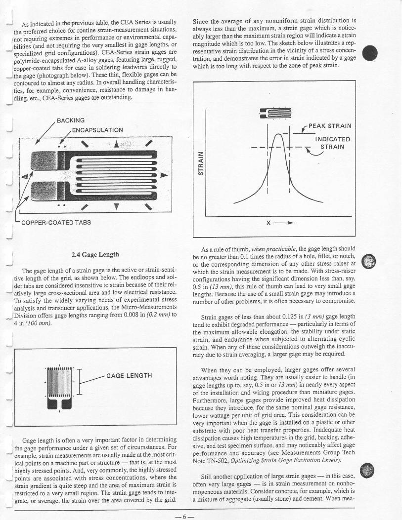
As indicated in the previous table, the CEA Series is usually
the preferred choice for routine strain-measurement situations'
not iequiring extremes in Performance or environmental capa-
bilitiei (and not requiring the very srnallest in gage lengths, or
" specialized grid configurations). CEA-Series suain gages are
oolyimide-encapsulated A-alloy gages, featuring large' rugged'
"oooer-coated tabs for ease in soldering leadwires directly to
-- thi gage (photograph below). These thin, flexible gages can be
conoured to almost any radius. In overall handling characteris-
tics, for examPle, convenience, resistance to damage in han-
dling, etc., CEA-Series gages are oqtstanding.
Since the average of any nonuniform strain distdbution is
always less than the maximum, a strain gage which is notice-
ably larger than the maximum strain region will indicate a strain
magnitude which is too low. The sketch below illustates a rep-
resentative sftain distribution in the viciflity of a shess concen-
tration, and demonstrates the error in strain indicated by a gage
which is too long with respect to the zone of Peak sfain.
J-r €
As a rule of thumb, rvhen practicab le, the gage length should
be no greater than 0.1 times the radius of a hole, fillet, or notch,
or the corresponding dimension of any other stress miser at
which the strain measurement is to be made. Vy'ith stless-miser
configurations having the significant dimension less than, say,
0.5 ]n ( 13 mm), this rule of thumb can lead to very small gage
lengths. Because the use of a small straiD gage may introduce a
number of other problems, it is oftefl necessary to compromrse.
Strain gages of less than about 0 .125 irr (3 nn) gage length
tend to exhibit de-sraded performance -Particularly in terms of
the m&\imum allowable elongation, the stability under static
strain, and endurance when subjected to altemating cyclic
sftain. When any of these considerations outweigh the inaccu-
racy due to strain averaging, a larger gage may be requircd
When they can be employed, larger gages offer several
advantages wofth noting. They are usually easier to handle (in
gage lengths up to, say,0.5 in or I3 mm) ir nearly every aspect
of the installation and wiring procedure than miniature gages.
Furthermore, large gages provide improved heat dissipation
because they introduce, for the same nominal gage resistance,
lower wattage per unit of gdd area. This consideration can be
very important lvhen the gage is instalted on a plastic or other
substrate with poor heat transfer Properties lnadequate heat
dissipation causes high temPeratures in the grid, backing, adhe-
sive, and test specimen surface, and may noticeably affect gage
performance and accuracy (see Measurements Group Tech
Note TN-502, Optimiiing Strain Cage Excitation Levels).
Still another application of large strain gages - in this case,
often very large gages - is in saain measurement on nonho-
mogeneous materials. Consider concrete, for example, which is
a mixture of aggregate (usually stone) and cement. When mea-
o
2.4 GageLength
The gage length of a sfiain gage is the active or shain-serlsi-
tive length of the grid, as shown below. The endloops and sol-
der tabs are considered insensitive to strain because oftheir rel-- atively large cross-sectional area and low electdcal resistance,
To satisfy the widely varying needs of exPedmental stress
analysis and transducer applicatioos, the Micro-Measurcments
-- Division offers gage lengths ranging from 0 0Q8 it (0.2 mn) to
4 in ( 100 mm).
@
ffifi[illilXiilil K GAGE LENGTH
Irl
Gage length is often a very imPortant factor in determiring
the gage performance under a given set of circumstances. For
example, sfain measurements are usually made at the most crit-
ical points on a machine Part or structure - that is, at the most
highly stressed points. And, very commonly, the highly stressedpoints are associated with sftess concentrations, where the
stmin gradient is quite steeP ard the area of maximum strain is
restricted to a very small region. The strain gage tends lo inte-grate, or avenge, the strai[ over the area covered by the grid.

suring strains in a concrete structure it is ordinarily desirable to
use a strain gage of sufficient gage length to sPan several Piecesof aggregate in order to measurc the representadve strain in the
structure. In other words, it is usually the aver4ge strain that is
sought in such instances, not the seYete local fluctuations in
strain occurring at the interfaces between the aggregate Partl'cles and the cement. In genelal, when measuring stlains on
structures made of composite materials of any kind, the gage
length should normally be large with respect to the dimensions"
of the inhomogeneities in the material.
As a generally applicable guide, when the foregoing consid-
erations do not dictate otherwise, gage lengths in the range from
0.125 to O.25 i\ ( 3 to 6 mn) are preferab\e. The largest selection
of gage pattems and stock gages is available in this range of
lengths. Furthermore, larger or smaller sizes generally cost
more, and larger gages do not noticeably irnprove fatigue life,
stability, or elongation, while shorter gages are usually inferior
in these characteristics,
2.5 Gage Pattern
The gage pattem refers cumulatively to the shape of the gdd,
the number and orientation of the grids in a multiple-grid gage'
the solder tab configuration, and various constructiofl features
which are standard for a Particular pattem. All details of the
grid and solder tab configuradons arc illustrated in the "Gage
Pattem" columns of Catalog 500. The wide variety of pattems
in the list is designed to satisfy the full range of normal gage
installation and srain measurement requirements.
With single-grid gag€s, pattem suitability for a particular
application depends primarily on the following:
Sold.ertabs -These should, ofcourse, be compatible in size
and orientation with the sPace available at the gage installa'
tion site, It is also important that the tab anangement be such
as to not excessively tax the proficiency of the installer in
making proper leadwire connections.
Gri.d width -When severe strain gradients Perpendicular to
the gage axis exist in the test specimen surface, a nafiow grid
will minimize the averaging error Wider grids, when avail-
able and suitable to the installation site, will improve the
heat dissipation and enhance gage stability - particularly
when the gage is to be installed orl a material or specimenwith poor heat transfer properties.
Gage resistance - In certain instances, the only difference
between two gage pattems available in the same series is thegdd resistance - typically 120 ohms vs. 350 ohms. When
the choice exists, the higher-resistance gage is preferable in
that it reduces the heat generation rate by a factor of three(for the same applied voltage across the gage). Higher gage
resistance also has the advantage of decreasing leadwire
effects such as circuit desensitization due to leadwire resis-
tance, and unwanted signal variations caused by leadwire
resistance changes with temperature fluctuations' Similarly,
when the gage circuit incltrdes switches, sliP rings, or other
sources of random resistance change, the signal-to-noise
ratio is improved with higher resistance gages oPerating at
the same Power level.
In experimental stress analysis, a single-grid gage would
normally be used only when the stJess state at the Poitrt of mea-
surement is known to be uniaxial and the directions of the Prin-cipal axes are known with reasonable accuracy (15")
These requirements severely limit the meaningful aPplica-bility ofsingle-grid strain gages in stress analysis; and failure to
consider biaxiality of the saess state can lead to large errors in
the stress magnitude inferred from measurements made with a
single-grid gage.
degree (or "tee") rosette can beernployed with *re gage axes aligned to coincide with the prin-
cipal axes. The dircctions of the principal axes can sometimes
be determined with sufficient accuracy ftom one of several con-
siderations. For example, the shape of the test object and the
mode ofloading may be such that the directions ofthe principal- axes are obvious from the symmetry of the situation, as in a
cylindrical pressure vessel. The princiPal axes can also be
defined by PhotoStress- testing.
For a biaxial stress state - a com-mon case necessitating strain mea-surcment - a two- or three-elementrosette is required in order to deter-mine the principal s[esses when thedirections of the princigal axes areknown in advance, a two-element 90-
go-degree rosette
In the most general case of sur-face stresses. when the dircctionsof the principal axes arg not knownftom other considerations, a three-element rosette must be used toobtain the principal saess magni-tudes. The rosette can be installedwith any orientation, but is usuallymounted so that one of the gdds isaligned with some significant axisof the test object. Three-elementrosetles are available in both 45-degree rectangular and 60-degreedelta configurations. The usualchoice is the rectangular rosettesince the data-reduction task issomewhat simpler fot this coflfiguration.
When a rosette is ro be emPloyed,careful consideration should alwaysbe given to the difference in charac-teristics be{rveen single-plane andstacked rosettes. For any given gagelength, the single-plane rosette issuperior to rhe stacked rosette in termsof heat transttr to the test sPecimer..generally providing better stability and accuracy for static strainmeasurements. Furthermore, when there is a significant straingradient perpendicular to the test surface (as in bending)' the
single-plane rosette will produce more accurate strain data
because all gdds are as close as possible to the test surface. Still
another consideralion is that stacked rosettes are genemlly less
conformable to contoured surfaces than single-plane rosettes.
On the orher hand, when there are large strain $adients in
the plane ofrhe test surface, as is often the case, the single-plane
rosette can produce enors in stnin indication because the grids
sample the strain at different points For these apPlications the
stacked rosette is ordinarily preferable. The stacked rosette is
also advantageous when the space for mounting the rosette is
limited.
I
Stacked roseEe
tf
t r / 4 \ ' 1
ff,h45-degree rosette
- 7
*!46-
<ffi>6o-d"sr; rosen"
- 7 -

for its strain gages and special sensors, The addition of options Shown below is a summary of the optional features offered.- f;:::ffil:1?:JiTffi'nH:1ilffii::esthecost'butthis Standardcatarogoptions o
'' 2.6 Optional Features
Micro-Measurements offers a selection of optional features
- r Significant reduction of installation time and costs
. Reduction -of
the skill level necessary to make depend-' able installations
- . lncreased reliability of applications
r Simplified installation of sensors in difficult locations oncomPonents or in the field
. Increased protection, both in handling during installationand shielding from the test environment
. Achievement of special performance characte stics
Availability of each option varies with gage series and pal-tem. Staldard options are noted for each seosor in Catalog 500.
Integral Terminals and Encapsulation
Option 17 Series Availability: EA, EB WA, ED' WD, EK' WK
Option E Series Availability: EA, ED, EK, EP
General Description: Option E consists of a protective encapsulation of polyimide film aPProximately I mil
10.Q01 n (0.025 mm)l thick. This provides ruggedness and excellent grid protection, with littie sacrifice in flex-
ibility. Soldering is $eatly simplified since the solder is prevented from tinning any more of the gage tab than is
delibirately exposed for lead altachmeut. Option E protects the grid from fingerprints and other contaminating
agents during installation and, therefore, contributes significantly to long-term gage stability. Heavier leads may
be attached dircctly to the gage tabs for simple static load tests. Supplementary protective coatings should still be
applied after lead attachmert in most cases. Temperature Limiti No de$adatioo. Grid Protection: Entire grid
and part of tabs are encapsulated. Fatigue Life: When gages are properly wiled with small jumpers, maximum
endurance is easily obtained. Size: Gage size is not affected. Strain Range: Strain range ofgages will be reduced
because. the addj.tional rcirforcement of the polyimide encapsulation can cause bond failure before the gage
reaches its full stuain capability. Flexibilityr Option E gages arc aknost as conformable on curved surfaces as
open-faced gages, since no intemal leads or solder ale present at the time of installation, Resistance Toleranc€:
Resistance tolerance is normally doubled when Option E is selected.
- 8 -

U
I
U
Option 5E Series Availability: EA, ED, EK, EP
Option l, Series Availability: EA, ED, EK' EP
Option lE Series Availability: EA, ED, EK' EP
General Description: ThJs option provides the same conlormable soft copper lead ribbons i-c used iu oprion L,
but with the addition of a i-mil 10.001-ir (0.025-mm)l thick encapsulation layer of polyimide film. The encap-
sulation layer provides excellent protection for the gage during handling and installation. It also contri^butes
greatly to inviionmental protection, though supplementary coatings are still recomrnended for field use Gages
ivittr Option lf wiil normally show better long-term stability than open-faced gages which are "waterproofed"
only afier installation. A good part of the reason for this is that the encapsulation layer Prcvents contamination of
the'grid surface from fingerprins or other agents during handling and itstallation. The presence of such contam-
inants will cause some loss in gage srability, even though the gage is subsequently coared with protective com-
pounds. Leads: Nominal ribbon size fol most gages is 0.012 wide x 0.004 in thick(0.30 x 0 10 mm) copPel rib-
tons. Leads are approximately 0-8 in (20 mm) lorg. Solder: +430'F (+2?0"C) rin-silver alloy. Temperature
Limit: +400.F (+)b0"C). Grid Protection: Entire gage is encapsulated. A short extensior of the backing is left
uncovered at the leaclwire end to prevent coltact between the leadwires and the specimen surface. FatigueLif€:
Fatigue life will normally be degraded by option LE. This occurs primarily because the copPer ribbon has,limit-
ed c"yclic endurance. Opiion LE is not often recommended for very high endurance gages such as the ED Senes.
Size: Matrix size is uncianged. Strain Range: Strain rarge will usually be reducedby the addition of Option LE'
Fledbiliiy: Gages with Option LE are not as conformable as standard gages. Resistance Tolerance: Resistance
toleralce is oormally doubled by the addition of Option LE.
- 9 -

Leadwire Orientation for Options L and LE
These illustrations show the standard orientation of leadwires relative to the gage paftem geometry for.options L and LE' The gen-
"i^i -i" ir ,frut tfr" f"ads ale Pamllel to the longest dimension of the Pattem. The illustrations also apply to leadwire orientation for
*.q,-, WX- ̂ na Wp-series gages, when the pattern shown is available in one of these series'
ootl IJLJ U|rl(3 or 4 tabs)
nTT
AIT
OnOTTTTTTtrE
TTTTTITTTT
JIEETT
o2.7 Characteristics of Standard Catalog
OPtions on EA-Series Gages
As in other aspects of strain gage selection, the choice of
options ordinarily involves a vadety of comPromises. For
instance, an option which maximizes a particular gage perfor-
mance parameter such as fatigue life may at the same time
require greater skill in installing the gage. Because of the many
interactions between installation attdbutes and performance
parameters associated with the options' the rclative merits of all
standard options are summadzed qualitatively in the chart
below as an aid to option selection. For comparison Purposes,the corresponding characteristics of the CEA Series are given in
the right-most column of the table'
Since, in strain measurcment for stress analysis, the standard
options are most frequently applied to EA-Series strain gages,
the informatior supptied in this section is directed primarily
toward such option applications.
When contemplating the application of an EA-Series gage
with an option, the first consideration should usually be
whether there is an equivalent CEA-Series gage that will satis-
fy the test requirements. Comparing, forexample, an EA-Series
gage equipped with Option W and a similar CEA-Series pat-
tem, it will be found that the latter is characterized by lower
cost, grcater flexibility and conformability, and superior fatigue
life. The only possible advantages for the selection ofOption W
are the wider variety of available pattems and the occasional
need for large soldering terminals.
It should also be noted that many standard strain gage types'
without options, are normally available from stock; while gages
with options are commonly manufactured to order, and may
thus involve a minimum order requirement.
In the table below, the respective performance Panmetersfor an open-faced EA-Series gage without options are arbitari-
ly assigned a value of 5. Numbers greater than 5 indicate a Par-ticular parameter is improved by addition of the option' whiie
smaller numbers indicate a rcduction in Performance.
INSTALLATION ATTHIBUTEOH PEHFORMANCE PARAMETER
STANDARD OPTIONS
E L LE
7 5 1 0
'10l' 7 7 1 0
I
7 8 a 4
3
3
- l 0 -

I
3.0 Gage Selection Procedure
The performance of a strain gage in any given application is
affected by every element io the design and manufacture of thegage. Micro-Measurements offers a great variety of gage tyPes
for meeting the widest range of strain measurcment leeds.
Despite the large number of variables involved, the process ofgage selection can be reduced to only a few basic stePs. Fromthe diagram below that exPlains the gage designation code, it is
evident that there a-re but five parameters to select. not counting
options. These are: the gage series, the S-T:'C number, the gage
length and pattem, and the resistance.
Of the preceding parameteff, the gage length and Pattern arenormally the fust and second selections to be made, based on
the space available for gage mounting and the nature of the
sEess field in terms of biaxiality and exPected strain gadient. Agood starting point for initial consideration of gage length is
Q-125 in (3 nnL This size offers the widest varieiy of choicesfrom which to select remaining gage parameteff such as pattem,
series and resistance. The gage and its solder tabs are largeenough for relatively easy handling and installation. At thesame time, gages of this length provide performance capabili-ties comparable to those of larger gages.
The principal reason for selecting a longer gage would com-monly be one of the following: (a) greater grid area for betterheat dissipation; (b) improved strain averaging on inhomoge-neous materials such as frber-reinforced composites; or (c)
slightly easier handling and installation [for gage lengths up to
0.50 in ( 13 tnn)1. Qn the other hand, a shortEr gage lesgth maybe oecessary when the object is to measure Iocalized peak
strains in the vicinity ofa stress concentration, such as a hole orshoulder. The same is true, of cou$e, when the space available
for gage mounting is very limited.
In selecting the gage pattern, the first consideration is
whether a single-grid gage or rosette is required (see Section2.5). Single-grid gages are available with different asPect(lergth-to-width) ratios and various solder tab arrangements for
adaptabiiity to differing installation requirements. Two-element90-degree rosettes, when applicable, can also be selected from a
number of different grid and solder tab configurations. With
three-element rosettes (rectangular or delta), the primary choicein pattem selection, once the gagelength has been determined, isbetween planar and stacked con-struction, as described in Sectrbz2.5.
The format of Catalog 500 isdesigned to simplify selection ofthe gage length and Pat te rn .Similar pattems available in eachgage length are grouped togethe!,and listed in order of size. Thestrain gages in the SuPer Stocksection of the catalog are the mostwidely used for stress analysisapplications. This section shouldalways be rcviewed first to locateall aPpropnate gage.
With an initial selection of the gage size and Paftem com-pleted, the next step is to select the gage series, thus determin-ing the foil and backing combination, and any other featurescommon to the series. This is accomplished by referring to thechad on page 5, which gives the recommended gage series forspecific test "profiles", or sets of test requirements. If the gage
series is to have a standard option applied, the option should betentatively specified at this time, since the availability of thedesired option on the selected gage pattern in that seriesrequires verificatioa durin-g the Procedure outlined in the fol-' ̂ . . , : - ^ - . .^^-^^Aruwurts P44Er4yu.
After selecting the gage series (and option, ifany), reference
is made again to Catalog 500 to lecord the gage designation ofthe desired gage size and pattem in the recommended series. Ifthis combination is not listed as available in the catalog, a simi-
lar gage pattem in the same size grouP, or a slighdy differentsize in an equivalent pattern, can usually be selected for meet-
ing the installation and test requircments' In exheme cases, it
may be necessary to select a[ alternate series and rcPeat thisprocess. Quite frequently, and especially for routine stoain mea-
surement, morc than one gage size and Pattem combination will
be suitable for the specified test conditions. In these cases, it iswise to select a gage from the Super Stock Listings to eliminatethe likelihood of extended delivery time or a minimum orderrequfement.
As noted under the gage Pattem discussion on page 7, thereare often advantages from selecting the 350-ohm resistance if
this resistance is compatible with the instrumentation to beused. This decision may be influenced, however, by cost con-siderations, particularly in the case of very small gages. Somereduction in fatigue life can also be expected for the high-res.is-tance small gages. Finally, in recording the complete gage des-ignation, the S-T-C number should be inserted from the list ofavailable numbers for each alloy given on page 4 of catalog500.
This completes the gage selection procedure. In each step of
the procedure. the Srain Gage Selectior Checklist on page 12should be refened to as an aid io accounting for the test condi-
tions and requirements which could affect the selection'
U
- l t -

4.0 Strain Gage Selection Checklist
This checklist is provided as a convenient, rapid means for
helping make certain that no crirical requirement of the test Pro-hle which could affect gage selecdon is overlooked' It should
be bome in mind in using the checKist that the "considerations"listed apply to relatively routine and conventional stress analy-
sis situations, and do not embrace exotic aPPlications involvingnuclear radiation, intense magnetic fields, exfteme centri.fugalforces, atrd the like.
5.0 Gage Selection ExamPles
In this section, three examples are given of the gage-selec-
tiort procedure in representative stress analysis situations. An
attempt has been made to provide the principal reasons for theparticular choices which are made. It should be noted, however,
that an experienced streas analyst does not ordinarily proceed in
the same step-by-step fashion illustrated in these examples.
Instead, simultaneously keeping in mind the test corditions and
environment, the gage installation constraints, and the test
requirements, the analyst reviews Catalog 500 and quickly seg-
regates the more likely candidates from among the available
gage-pattem and series combinations in the aPPropriate sizes'
The selection criteria are then refined in accordance with the
particular stain-measuement task to convelge on the gage or
gages to be specified for the test Progam. Whether formally or
otherwise, the knowledgeable practitioner does so in the light of
parameter selection considerations such as those itemized in the
preceding checklist.
A, Design Study of a Pressure Vessel
Strain measurements are to be made on a scaled-down plas-
tic model of a pressure vessel. The model will be tested stati-
cally at, or near. room tempemture; and, although the tests may
be conducted over a period of several months, individual tests
will take only a few hours to run.
o
Selection SteP: 1
Paameter: Gage Lenglh
Selectian SIep: 3Paameter: Gage seties
Selection SteP: 2
Panmetea: Gage Pati'ern
CONSIDERATIONS FORPARAMETER SELECTION
Ytr strain gradientsE area ol maximum strainE accuracy r€quiredI static strain stabilityE maximum elongationE cyclic enduranceE heat dissipationE space lor installationE eas6 of Installation
strain gradients (in"Planeand normal to surface)biaxiallty ol stressheat dissipationspace for installatlonease of installationgage resistance availability
E type of strain measurementapplication (static, dynamic,post-yield, etc.)
E operatingtemperatureE test durationE cyclic enduranceE accuracy requiredE ease of installation
type of measurement {static,dynamic, post-yield, etc.)installation environment -laboratory gr fieldstability requkementssolderihg sensitivity ofsubstrate (Plastic, bone, etc.)space available for installationinstallation time constraints
heai dissipationleadwire desensitizationsignal-io-noise .atio
test specimen materialoperating temperature rangeaccuracy requrreo
trtrtrtrtr
Selectlon Slep: 4
Paftmeter: Oplions
trtr
trtr
Selec on SIep: 5 u
Parametelr Gage Resistance E
tr
Seteclian Step: 6 trParcneter S-1-c Numbet tr
tr
Gage Selection:
L Gage Length - Very short gage lengths shoutd be avoided
in order to minimize heat dissipation problems caused by
the low thermal conductivity of the plastic. The model is
quite large. and apparcnlly free of severe strain gradients;
therefore. a 0.25-in (6.3-nn) gage length is specified,
because the widest selection of gage pattems is available in
this length.
2. Gage Panen- In some areas of the model, the directions
of the principal axes are obvious from considerations of
symmetry. and single-grid gages can be employed. Of the
pattems aYailable in the selected gage length, tbe 250BF
pattern is a good compromise because of its high grid resis-
tance which will help minimize heat dissipation Problems.
o-12-

t
In other areas of the model, the directions of the princiPal
axes are not known, and a three-element rosette will be
required. For this purpose, a "planaC'rosette should be
selected, since a stacked rosette would contribute signifi-cantly to reirforcement and heat dissipatiorl Problems.Because of its high-resistance grid, the 250RD Pattem is agood choice.
Gage Series - The polyimide (E) backing is preferred
because its low elaitic modulus will minimize reinforce-
ment of the plastic model. Because the normal choice ofgrid alloy for static strain measurement at room temperatureis the A alloy, the EA Series should be selected for this
application.
Optrons -Excessive heat application to the test model dur-ing leadwire attachment could damage the material. OptionL (prcattached leads) is therefore selected so that the instru-ment cable can be attached direcdy to the leads without theapplication of a soldering iron to the gage proPer. OPtion L
is preferable over Option LE because the encapsulation inthe latter option would add reinforcement.
Resistance -Ir.this case, the resistance was determined irl
Step 2 when the higher rcsistance altemative was selectedfrom among the gage pattems: i.e., in selectirg the 2508F
over the 250BG, and the 250RD over the 250RA. Theselected gage resistance is thus 350 ohms.
Gage Selection:
L Gage Length - A gage length which is small with respect
to the frllet radius should be specified for this application. Alength of 0.015 in (0.38 mm) is preferable, but reference to
Catalog 500 indicates that such a choice severely limits theavailable gage pattems and grid alloys. AnticiPating Prob-lems which would otherwise be encountered in Steps 2 and
3, a gage length of 0.031 in (O8 rzrz) is selected.
2. Gage Paftem - Because the gear is a spur gear, the dircc-
tions of the principal axes are known, and single-grid gages
can be employed. A gage pattem with both solder tabs at the
same end should be selected so that leadwire connectionscan be located in the clearance area along the root circle
between adjacent teeth. In the light of these cousiderations,
the 03lCF pattem is chosen for the task.
3. Gage Series -Low strain levels are expected in this appli-
cation: and, furthermore, the sfain signals must be tlans-mined through slip rings or tfuough a telemetry system toget ftom the rotating component to the stationary instru-mentation. Isoelastic (D alloy) is preferred for its highergage factor (nominally 3.2, in contrast to 2.1 for A and Kalloys). Because the gage must be very flexible to conform
to the small fillet ndius, the E backing is the most suitablechoice. The maximum test temperature is not a considera-
tion in this case, since it is well within the recommendedtemperature range for any of the standard backings. The
combinadon of the E backing and the D alloy defines theED sase series.
4. Options -For protection of the gage grid in the test envi-ronment. Option E, encaPsulation, should be sPecified.Because of the limited clearance between the outside diam-eter ofone gear and the root circle ofthe mating gear, a par-
ticularly thin gage installation must be made; and very small
leadwires will be attached to the gage tabs at 90' to the gdd
direction. and run over the sides of the gear for conleclionto laryer wires. This requirement necessitates attachmelt ofthe small leadwires after gage bonding, and preYents the useofpreattached leads.
Resistorce - In the ED-Series version of the 03lCF gage
pattem, Catalog 500 lists the rcsistance as 350 ohms. The
higher resistance should usually be selected whenever thechoice exists, and will be advantageous in this instance in
improving the signal-to-noise ratio when slip rings are used.
S-T-C Nunber -D alloy is not subject to self-temPeraturecompensrlion, nor is compensation needed for these tests
since only dynamic stnin is to be measured. [n the ED-
Series desi-snation the two-digit S-T-C number is replaced
by the Ieners DY for "dynamic."
5.
6.
Gage Designation:
Combinin-g the results of the above selection procedure, thegage to be employed is:
ED-DY-03 t CF-350/OPtion E
- J .
6. S-T-C Number - Ideally, the gages should be self-tempera-ture-compensated to match the model material, but this isnot always feasible, since Plastics - panicularly reinforcedplastics - vary widely in thermal expansion coefficient.For unreinforced plastic, S-T-C 30, 40 or 50 should usuallybe selected. If a mismatch between the model material andthe S-T-C number is necessary, S-T-C 13 should be selected(because ofstock status), and the test performed at constanttemperaure.
Gage Designations:
From the above steps, the sftain gages to be used are:
EA-30-250BF-35OiOption L (single-grid)EA-30-250RD-35O/Option L (rosette)
B. Dytramic Stress Analysis Studyof a Spur Gear in a llYdraulic PumP
Stnin mensurements are to be made at the root of the geartooth while the pump is operating. The fillet radius at the toothroot is 0.125 in (o[ about 3 nm) and test temperatures areexpected fo range from 0" to +180"F (-20' to +80'C).
0
- 13_

C. Flight-Test Stress Analysisof a Titanium Aircraft Wing Tip Section -
With, and lryithout, a Missile Module Attached
The operating tempetaturc range for strain measuements isfrom -65' to +450'F (-55' to +230"C), and will be a dominantfactor in the gage selection.
Gage Selection:
1. Gage Length - Preliminary design studies using thePhotostuess photoelastic coating technique indicate that agage length of 0.062 in (1.6 nrn) represents the best com-promise in view of the strain gradients, areas ofpeak strain,and space for gage installation.
2. Gage Pattem- with information about the sEess state anddirections of principal axes gained ftom the photoelasticcoating studies, there are some areas of the wing tiP wheresingle-grid gages and two-element "tee" rosettes can beemployed. In other locations, where principal strain direc-tions vary with the nature of the flight maneuver, 45-degreercctangular rosettes are required.
3.
The strain gradients are sufficiently steeP that stackedrcsettes should be selected. From Catalog 500, the forego-ing requirements suggest the selection of 060WT and'060Vr'R gage patterns for the stacked rosettes, and the062AP pattern for the single-grid gage. In making thisselection, attention was given to the fact that all three pat-tems are available in the WK Series, which is compatiblewith the specified opemting temPerature range.
Gage Seties -The maximum operating temP€rature, alongwith the requirement for static as well as dynamic strainmeasurement, clearly dictates use of K alloy for the gridmaterial. Eifter the SK or WK Series could be selected, butthe WK gages are preferred because they have integral lead-wues.
Options - For ease of gage installation, Option { withintegral soldering terminals, is advantageous. This option isnot aDDlicable to stacked rosettes, howevef, and is thereforespecified for on.ly the single-grid gages.
5. Resistance - lvhen available, as in this case, 350-ohmgages should be specified because of the benefits associat€dwith the higher gage resistance.
6. S-T-C Nun&er - The titanium alloy used in the wing tipsection is rhe 6A1-4V type, with a thermal expansion coef-ficient of 1.9 x lO{ per 'F (8.8 x 10" per'C). K alloy ofS-T-C number 05 is the appropriate choice.
Gage Designations:
WK-05-062AP-35o/Option W
wK-05-06owr-3s0wK-o5-06owR-350
o
;
- 1 4 -

, -VISHAY
V Strain Gage Application Requirements
TitleName
Company Phone
Address
Date
1. TEST DESCRIPNON
Sialic fl Dynamic f, Maximum Strain
Test Duration or NumbEr of Cycles
Marimum TemDerature
T€mperature Range Ouring Tesl
'Iime at Maximum Temperatur€
Description of Tesl Environment
TO BETESTEDMATERIAL
Description
2.
Temperature coefficient of Expansion - ppm D'F f|'c
Allowable Surface Pr€pa.ation:
Ch€mical Sotuents (specily limitations)
Silicon Carbide AbrasionConditionerANeutralizer 5A
YEsO t toDYesO NoOYesfl NoO
Maximum Allowable CurE TemDerature
.! 3. GAGE INSTALLATION ENVIRONMENT
Indoor0 Outdoorfl Approximate T€mperature
Maximum Allowable Bonding Pressure
Humidity
INSTFUMENTATION AND CIRCUITS
Excitalion VoltageDescriotion ot Fleadout Instrument
Clrcuits: t/4 Bridge D 1/2 Bridge 0 Fu Bridge 0
Leadwire Lengths
5. GENERAL INFOBMATION
Number of Test Specimens Number ol
tndude st<etch ot test piece showing dimensions, surhce contouti obsttuclions, and allowade gaging arca- Show ewru.imate s'ain field, itKnown,
lncluda a desc plion of all special rcquitemenE,

Reference 2

t-
T-t
'
u
and Gage Factor Variation with TemperatureStrain Gage Thermal Output
L0 Introduction
Ideally, a stsain gage botrded to a test part wodd rcspondor y to the applied strain in the partt aud be unaffected by othervadables ill thE environment. Unforfimately, the resistaucestrain gage, in cornnon s/ittl all other senso$, is somewhat lesstlan perfect. The electrical resistaDce of the strai! gags variesnot only with strain, but with temperature as well. In addition,the relationship between strain and resistance change, the gage
/actar, itseu varies with temperature. These deviatious ftomideal behavior can be important under certain circumstances,aad.eaeea$e-siglifiea$t errors if not pmperly accourted for.When the underlying phenomeaa are thoroughly utrderstood,however, the errors can be confolled or yirtually elimioated bycpmpensation or correction.
In Section 2.0 of :dnis Tech Note, thermal output (soE€timesrcferred to as "temperatffe-induced apparcnt stain") is clefine4and the causes of this effect are described. Typical magnitudesof.the thermal output are then given, followed by the common-ly used methods for compensatiou and conection. Section 3.0Eeats gage factor variations with temperature in a similar butbriefer manner since this error source is generally much lesssignificant. Methods for the simultaneous correction of boththermal output and gage factor errors an glven in Seaion 4.0,accompauied by numerical examples.
2.0 Thermal OutputOnce atr ilstalled strain gage is coEnected to a stain indica-
tor and the instlument balanced, a subsequent change in thetemperature of the gage installation will normally produce aresistance change in the gage. This temperature-induced resis-tance change is independent of, and unrelated to, the mechani-cal (stess-induced) strain in the test object to which the straingage is boncled. It is purEly due to temperatue change, and isthus called the riermn I ou@ut of be gage.
Thermal output is poteutially the most serious eror sourcein the practice of static sEais measuremetrt with stain gages. Infact, when measuring strains at temperatures remote from roomtemperdture (or ftom the initial balance temperature of the gagecircuit), the eror due to tbermal output, if not contolle4 can bemucb greater than the magllihrde of the stai! to be measuled.At any temperatue, or ia any temperahrre range, this errorsource requires carefii consideration; and it is usually neces-sary to either provide compensation for thermal ouq)ut or cor-lect the strain measwements for ih presence.
Thermal oltput is caused by two concurent and algebraical-ly additive effects in the strain gage installation. First, the elec-trical resistivity of the grid conductor is somewhat temperaturedependent; a[d, as a r€sult, the gage resistance varies with tem-pelaturc. The se.ord contributiotr to thermal output is dus to thedifferential thennal expa$ioo between the grid cooductor andthe test part or substrate nat€rial to which the gage is bonded.With tempemtule change, the substrate expands or contacts;and, since the strain gage is frmly bonded to th€ substlate, thegage grid is forced to undergo the same expansion or conEac-tion. To th€ ext€Et thal the thermal expansiou coef[cient of thegrid differs ftom that of the substate, the grid is mechanicallystrained in confomiqg to the ftee expansion or contraction ofthe substraie. Because the grid is, by design, shain sensitive, thegage exhibits a rcsistance change proportional to the differentialexpansion.
Each of the two thermally induced resistance chalges maybe either positive or negative in sign with respect !o that of thetemperature change, and the net thermal output of the straingage is the algebraic sum of these. Thus, expressed in terms ofunit resistance change, the thermal ouq)ut becomes: .
fan) l "^ ^( t+x, l . . lr_ l = t Ec+F. , t_ l (a r_ao) ld r ( l )\h )no f -
- \1 -vo4) ' I
Strain GageTempetature Effects
o -VISHAY
U
I NEASUEEIIHIIS Il @ w P l
€Copyright Measurements Group, Inc., 1993All Righis Reserv€d.

where, in consistent units:
fanl| =: | = unit chanse irt resistance frour the initial refer-| & /za ence resislance, Ro,
"aused by change ir tem-
perature resulting in thermal outpul
BG = temperature coefncient of resistaoce of thegrid conductor
Fc = gage factor of the saain gage.t
Kr = transverse sensitivity of the strah gage.
v0 = Poisson's ratio (0.285) ofthe standard test ma-terial used ir calibrating the g€e for its gagefactor.
(as- ad = di.ffetence iu thermal expansion coefEcientsof substrate and grid, respectively
Af = temperature change &om an arbitrary idtialrcfef,ence temPerahue.
The conection factor for transverse sensitivity t(l + Kl)/(1 - zsK)l is incluiled in Eq. (1) to account for the fact that thestain io the gage gdd due to differential themal exPansion isequal-biaxial, while the gage factor, F6, refers to the stai.s seo-sitivity as calibrated in unia:ial stress state, with a principalstrain ratio of 1/(-0.285).
It should oot be assumed ftom the forE of Eq. (1) that theth€rmal output is linear with teEperature change, because a1l ofthe coefEcients s'ithin the brackets are themselves functions ofteEperature, The equation clearly demonstrates, however, thatthermal output depends not only on the nature of the sttaingage, but also on the material to which the gage is bouded.Bdcarise-of tEiS; meimdl output data arc meanilgful only whenrefened to a particular t ?e of saain gage, bonded to a specifiedsubsEate material.
For convenience in corecting measured strah data for ttrer-mally iaduced resistance chauges, the thermal output of thegage is usually expressed in staitr units. Thus, dividing Eq. (1)
by the gage factor setting of the instrument,
Ia^ )l .&' i" '"
€ .To = -=rJ
fl
wberc: ey6 = thermai output in stain units; that is, the strainmagnitude registered by a stain indicator (witha gage factor setting of Fr), wheu the gage in-stallatiou is subjected to a tempemture change,/7, under conditions of ftee thermal expansionfor the substrate.
When measuring stress-ilduced strains at a temperature dif-ferent ftom the initial balance temperalue, the therEal outPutfrom Eq. (2) is superimposed on the gage output due to
tb this Tech Notc, the gage faclo! of the 5trail gagc (as specified by thepackage E[gileelirg Data Sheet) is ideotifred as Fa' to distinguish it Aoruthe gage faclo! scttidg of the measuitrg ilstsumetr! derct€d here by Fr.This distioctio. is ihportad, since tbe gage factor senilg of the ilstrulneEay solretiE s, as a Eatter of codvedeDcc or utility, be difrEent ftoE thatofthe ga€e.
mechanical strain, causilg the measurement to be in error by
ttlat anounl Many factors affect ths lhermai outPut of stsai!
gages. Some of the nore importatrt are: test sPecimen Eaterial
aud shape, grid alloy ard lot, gage series atrd PatterE, traNvslse
seositivity of th" gage, bonding and encapsulating materials,
and instailation procedures. It is trever possible for Micro-
MeasureBeuts to prcdict exactly what the thermal outPut of anygage will be when the uset has bonded it to a test structure.Eyen itr cases wbere applications involve the same matedal asthat used by Mcro.MeasulemeDts in its tests, differences can beexpected sinca stluctural materials vary in thernal exPansioncharacteristics Aom bt to lot. The best practice is always toevaluate ooe or more gages uader thermal conditions as nearlylike dlose to be encouutercd in the testing program as possible.
Figue 1 shows the variatioq of thernal output with tomper-ature for a variety of strain gage alloys bonded to steel. Thesedata are illustrative onln and uot for use in makitrg coGections.It sbould be noted, in fact, that the curves for cotrstartan audKarma are for qon-self-temperatwe-comPensated alloys. Withself-temperature compersaaot (Section 2.L 2), as employed iuMicro-Measuements straia gages, the thermal ouQut chalac-terisiics of these alloys are adjusted to minimize the errot overthe normal ralge ofworking iemPerahres.
TEMPEFATURE -'F
Fig. 1 - Thermat output variation with temperuture lor sev-erul strain gage allols (in the as-rolleil metullurgical coruIi'tion) boniledto steeL
As inrlicated by Fig. l, the enors due to thermal output canbecome extremely large as temperatues deviate ftom the a$i-tary rcference temperature (ordinarily, room temPeratue) \ffithrcspect to which the thermal output is measued. The illustra-tion sbows distincfly the necessity for compensatioa or correc-tiou if accurate static stailt measurcmeats are to be made fu] anenvironment irvolving temperature chatrges.
With respect to the latter statement, it should be remarkedthat if it is feasible to bring the gaged test Part to the test tem-pe'Jrffie in the test envirowaent, m?I.ntaining the test part com-pleoely Aee of mechanically or thermally induced stesses, and
l-
I
=
F
(2)
IEMPEBATUFE-'C
- 2 -

.r-if--' -
balarce the sEaitr indicator for zero stain under these condi-tions, no thermal output error exists whsn subsequent straiEmeasursments are made at this tetnperature.In other words,whetr no temperature change occum between the stsess-ftee andstessed conditions, staio measulements can be made withoutcompensatiag or correcting for thermal outPut, In practice,however, it is rare that the foregohg requireEents can be satis-fie4 aqd tbe stress aoalyst ordinarily fitrds it necessary to takefull account of thermal output effects.
Also, in the case of purely dynaEic strain measurcments,where there is no need to maintain a stable zero.shain rcfer-ence, thermal output may be of tro consequence. This is becausethe frequency of the dynamic stain signal is usually very highwith respect to the ftequetrcy of temperah.[e chatrge, atrd thetwo signals are readily separable. If, however, there is combinedstatic/dynamic strain, aod the static component must also bemeasured, or if the ftequency of iemperature chauge is of thesa.me order as the stain frequency, thermal output effects mustagain be considered.
2.1 Compensation for Thermal Output2.1.1 Compensating @ummy) Gage
In theory at least, the error due to thermal output can becompletely elim.itrated by employing, ia conjunction with the"active" suain gage, but connected itr atr adjacent arm of theWheatstone bridge circuit, an identical compensatiog or"duEmy" gage - mouDted on an unsfiained specimen madeftom the identical material as tbe test pad, and subjected alwaysto the same tempelahrre as the active gage. Under these hypo-tbeticql conditions, the thermal outputs of the two gages shouldbe identical. A.od, siuce identical resistaace cha.nges itr adjacentalms of ths Wheatstone bridge do not unbalaace the circuil thethermal outputs of tbe active and dumrny strain gages shouldcancel exacdy - leaving only the stress-induced strain in theactive strain gage to be rcgistered by the stain bdicator. Forthis to be pr€cisely true rcquires additionally that the leadwiresto the active and dummy gages be of the same length and berouted together so that the temperature-induced resistancechaoges also match identically.
The principal problems etrcoutrtered in this method of tem-perature compensation are those of estabiishing and maintain-ing the tbrce sets of idsntical conditions poshiated above. Tobegin with, it is sometimes very difEcult to arrange for theplacement of an utrstrained specimeu of the tEst material in drctest euviroDment and even more difEcult to make certain thatthe specimen remains unsEained under all test conditioas.There is a furlher difEculty in ensuring that the temperature ofthe compeusathg gage on the unstrained specimen is alwaysidentical to the teEperahre of the active gage. This problembecomes poticularly severe whenever tiere are temperaturegradients or tmnsients in the test environmetrt. An4 as indicat-ed in the preceding paragraph, the same considerations apply tothe leadwires. Fimlly, it must be recognized that no two staingages - even Aom the same lot or package - are preciselyidentical. For most static strain measurement task itr the gener-al neigbborhood of room temperatue, the difference in therrnaloutput betweer two gages of the sa-@e type ftom the same lot isnegligible; but the difference rnay become evident (atrd signifi-cart) when measuring stains at temperahue extemes such asthose involved in high-temperatule or cryogenic work. In theseinstarces, point-by-point correction for thermal output willusually be trecessary. with non-self-temperature-compe$atedgages, the gags-to.gage differences in thermal output may be so
great as to preclude duumy compensation fo! temPeratureswhich are remote ftom room temperature.
Iu general, when the tbree identity criteria already men-tioned can be well satisfied, the method of compensatiag with adumroy gage is a very effective tecbnique for contolling thethermal output error. There is, moreover, a special class of skainmeasurement applications which is particularly adaptable tocompensation of thermal ouq)ut with a secoud gage. This classcoosists of those applications ill which the ratio of the strains attwb different but closely adjacetrt (or at least thermaly adja-ceot) points on the test object are known a priori. I-ncluded inthis class are ba$ in pule tolsion, beams iu bending, columns,diaphngms, etc., al1 stessed within theirrespective proportion-al liEits. In these applications, the compensating gage can oftenbe located sEat€gically oo the test member itseif so as to pro-vide two active gages which undergo the same tempeEture vari-ations wlile sensing straiDs that are prcfsrably opposite i! signaqd of known ratio. The two gages in adjacent arms of theWheatstone bridge circuit then fttnction as an active halfbridge.
For exanple, when stain measurements are to be made otr abeam which is thin enough so that under test conditiotrs the tem-pemtules on the two oPposite surfaces normal to the platre ofbending are the same, the two straio gagos can be installeddirectly opposite each other on these surfaces (Fig. 2a). Theactive haif bridge thus formed will give efiective temperahuecompensation over a reasonable range of temperatures and,
G)
Fig. 2 - Examples illustrating lhe use oJ a secorul (compen-sating) strain gage in an adjacent YFheatstone bridge arm tocdncel the effect of thermal outl,ut,
lnL
WE
ACTIVEGAGE
(b)
P
G)
A L 2
L3c L l
- 3 -

si[ce the saains sensed by the gages arc equal in magnitude andopposite itr sign, will double the outPut sigtral from theWl.eatstone bridge. Similarly, for a bar in Pure to$ion (Fig' 2b)'the two gages can be installed adjacent to each other and alignedalong the principal axes of the bar (at 45" to tbe lorgitudinalaxis). As in the case of the bean, excellent tomperahre compen-
sation cau be achieved, along with a doubled output signal'
When making strain measurements along ttre axis of a col-
umn or tension link, the compensating gage can be mounted on
the test member adjacent to the sxial gage atrd aligned tratrs-ve$ely to the longitudinal axis to sense the Poisson strain
@ig. 2c). The resuit, again, is compensation of the tlprmal out-put, accompanied by an augmented output signal lby the factor(1 + y) in this casel. It should be borne in mind in this applica-tion, however, that the accuracy of the strain measurement issomewhat dependeEt upotr the accuracy v,/ith which thePoisson's ratio of the test material is knowu. The percent error instrai.u measurement is approximately equal to t'(1 + t/) times thepercent euor in Poisson's ratio. A further caution is necessarywhen stair gages ale moutrted bansve6ely on small-fiameterrods (or, for that matter, in small-radius fillets or hol€s)' Hineshas shown (see Appehdix) that under these conditioDs the ther-mal output characteristics of a strain gage arc di.fferent thanwhen the gage is mounted on a flat surface of the same material.
In all strain-measuremeut aPPlicatioqs which involvemounting the compensaring gage ou the test object ilielf, ,herelationship hetween the strains 4t the two locations must beknown with cenainty. In a beam, for example, there must be soindeterminate axial or torsional loading; aud the bar in torsionmust riot be subject to indeterEirate axial or bending loads.This requirement for a priori knowledge of the sbain distribu-tioo ach.rally places. these and most simila! applications in theclass of transducers. And the same method of compensatiou isuniversally employed in commercial strain gage tlansducers.Such ftansducers, however, oldioarily employ fttll-bridge cir-cuits and special a[angemeats of the straiD gages to eliminatetle effects of exEaneous forces or moments.
2.1.2 Self-Temperature-Compensated Shain Gages
The metallurgical propsrtios of certain stain gage alloys -
in particular, constantan and modified Karma (Micro-Meastue-ments A and K alloys, respectively) - are such that these alloyscan be processed to mininize the thermal output over a widetemperature range wben botrded to test natedals with themalexpansion coefriients for which they are htended. Stsain gagesemploying these specially processed alloys are referred to ass e If - temp e r ai4re- c o np ens at ed. -
Since the advent of the self-temperature-compensated straingage, the requirement for a matcbi€ utrstrained dummy gage inthe adjacent arm of the Wleatstorc bridge has been relaxedconsiderably. It is now normal practice when making strainmeasureme!.ts at or near room tempenture to use a single self-teEp€raturc-compensated gage in a quarter-bridge aEangement(with a tbrce-wle hookup), completing the bddge circuit witb astable fixed rcsistor ir the adjacent arm (Fig. 3). Such 'bridge-
completiou ' resistors, with very low tenperatue coefEcieuts ofresistance, are supplied by Micro-Measuremeuts atrd are incor-poEted i.n most Eodem.strain hdicato$.
Figure 4 illustrates the thermal output characteristics oftypical A- and K-al1oy self-temperatue-competrsated strai!
Fig, j - A single self-temperature-compenssted strdin gagein a three-wie quarter-bri.dge circuit exemplifies modernstrain gage pradi.ce for stress analysis meaaurernents.
gages. As demonstrated by the frgure, the gages are designed tomininize the thermal output over the temPerah.ue rarge fromabout 0" to +400'F (-20" to +205"C).When the self-tempera-ture-compensated strain gage is bonded to material having thethernal expansion coefEcient for which the gage is intended,and when opemted within the temperaturc range of effectivecompensation, strain measurements can often be made withoutthe necessity of conecting for thermal output. If correction forthermal output is needed, it can be made as shown in the fol-lowins sections.
-100 o +100 )300 +400lI PENAfl'RE-'F
Fig, 4 - Typical thermal ouE ut variation vith tenperatute
for self-temperature-contpensated constantan (A-alloy) andmodifud Kann (Ka oy) strain gages,
Self-temperature-compensated straitr gages can also. be usedin the manner describ ed in Sectian 2.1'1.That is, when circum-sta.nces are such that a pair of matched gages can be used LIadjacent arEs of the bridge circsit, with both gages maintainedat the same temperature, and with one of the gages unshained(or strahed at a determinate ratio to the othet gage), excellenttempemtur€ competrsation car be achieved over a wide temper-atlrrc range,
The designations of Miclo-Measulements self-temperature-compensated strain gages include a two-digit S-T-C uumberideutifying the qominal thermal expansion coefficient (inppm/"F) of the material on which the gage will exhibit optimumthermal output characteristics as shown in Fig. 4. Micro-Measurcme s constantatr alloy gages are available in tle fo1-lowing S-T-C numbers:00,03,05,06,09, 13, 15, 18,30,40, ald50. S-T-C numben of 30 aud bigher are iffended primarily for
1 + 1 0 05 - o
I
e *ao: -4oo
i -ro+ -€oo
o- 4 -
i
'J

3.0
12.9
6.4
1 1 . 1
'10.2
6.0
7-O
0.8
14.5
2.7
6.6
0.3
6.0
5.7
5.O
9.6
8.0
'i 3.0
4.4
4.9
0.0
2.4
05
05
05'
13'
09
09
15'.
03'
06
00
00.0303
I;:=ll;l|";"I|
1'.6 I
| 12.1
|
l,o I
l;l| ,":, II e: I
l',"l| ,0., It l
1,, I| "' II It 144 1
l;lIil
I n-uutuln,"o II ALUM|NUMAlloy, II zoz+tt',zozs-ta I
I eenv'-.,uN, ou." II BERYLLTUM coPPER, II cu 7s, Be25 |I BBASS, cart.ldge, II cu70,zn30 |I ERoNzE, Phosphor, II c u e 0 , s n 1 0 |I
cAsr lRoN, slay II coPPER, pure
II cLAss, II
Soda, Um6, Silica I
I rNcoNEL. II
Ni-crFo alloy I
I tNcoNslx, I,I
Ni{rFe alloy I
I TNVAR, II
Fg-Nialloy I
I MAGNESIUM Alloy', I
I Az.31B II
MoLYBDENUM', pure I
I riror|El, II
Ni4u alloy I
I NTCKEL-A, II Cij:Zi:Nl alloy II ouABrz,tus€d II sTEELAlloy, I| 4340 |I STEEL, cerbon, I|
1008, 1018' I
I STEEI, Stalnles€, II Age Hardenable I| 07-1PH) |I srEEL, srainte€s, IlAgeHardenable I|
(17.7PH) I
I STEEI- Stainless, IlAgeHardenalle I|
(PH15-7Mo) |
I STEEL, Stalnless, I
I Austgnltlc (304')
ISTEEI. Stalnle6s, IAustenitic (310)
|STEEI- Stalnless, IAustenitc (316)
|STEEL, Stainless, IFenttlc (410)
ITlN, pur€
|TlTANlUM,purB
ImAi'llUM Alloy, I8A1-4v'
I1ITANIUM SIUCAIE', Ipolycrystalline
ITUNGSTEN, pure
IARCONIUM, pur€
Icurycstype
aTABLE I - Noninal Thermal Expansiotr Coefficients
of Engineering Materialsuse on plastics. In K alloy, the range of S-T-C numbers is morelimite4 and consists of 00, 03, 05, 06, 09, 13, and 15. For refer-ence convenience, Table 1 lists a aumber of engiaeerbg materi-als, and gives nominal values of the Fabrenheit and Celsiusexparsion coefficients for each, along with tbe S-T-C numberwhich would nosmlly be select€d for strain measurements onttnt material. The table also ident'des those test materials usedin determining the pubtshed thermal output curves for Micro-Measurements self-temperature-compeDsated sEain g€es.
If a strain gage with a panicular S-T-C number is installed ona material with a nooEatching coefrcient of expamion, thethernal output characleristics will be altered ftom those shownin Fig. 4 by a geaeral rotation of the curve aboBt the room-tem-perahue reference point (see Sectioz 2.2.5). When tlp S-T-Clumber is lower than the material expansion coefficient, therotation is counterclockwise; and when higher, clockwise.Rotation of the thermal output curve by intetrtiodally mismatch-ing the S-T-C number and expansion coefEcient can be used tobias the therrnal ouEut cbaracteristics so as to favor a particularworking tempemtur€ range.
2.2 Correction for Thermal Output
Depending upon the test temperaturc and the degree of accu-racy required in the shain measuement it will sometimes benecessary to make corrections for thermal output, evetr thoughseu-temperature-compensated gages are used. In any case,when makitrg strain measurements at a temperatue differentfrom the instrumeot balatrc€ leEperature, the i.ndicat€d strain isequal to the sum of tbe stess-induced strain in the test objectand the thermal output of the gage (plus the saai! equivalent ofaay other resistance changes in the gage circuit). With the ther-mal output expressed in stain units, as in Eq. (2), cofiection forthis effect is made by sinply subuacting (algebraically, withsign) the thermal output ftom the i[dicatEd sEain.
As an aid to the user i! coEecting for temp€ratue-dependentproperties, the Engineering Data Sheet in each package ofMicro-Measurements A- and K-alloy saain gages includes agraph showing the thermal output and gage-factor variation withtemperature. Figure 5 is typical (for A alloy) of the graphssupplied with the gages. Io addition to plots of thermal outputand gage factor variation, polynomial equations are provided(in both Fabrenheit and Celsius uaits) for the thtrmal outputcuwe. AJso given on the graph are two other important items of
I
IIiERMAL OUTPUT
E I
i . EE r iY i: :: !
F E
F -
9 g
E P
* {i i r€ ?
frEta
oou(Pur
suppli€d with Micro-MeasuemenB strai! gagcs.**NomiEal values at ot oear roolr tempelature for teoperatule coef-
fciedt of expaDsio! values.
rEerEooN:!q!!3!g!!!9[ rEs.PATrqN:!499 cooel!]lzl_ ENcigg
Fig, 5 - Replica oI gqth incluled on the Engineering DataSheet a.ccompanying eaah package of Micro-Meosuementss e lf-tezqt eratur e -c omp e n s ated s train g ag e s.
- 5 -

information: (1) the lot number of the stain gages, and (2) thetest material used in measuring the therrral output characteris-tics. It should be noted that the thermal output data are speci6-cally applicable to only gages of the designated lot number,applied to the same test material.
2.2,1 Simple Procedure
Approiimate correction for thermal output can be accom-plished most directly and easily using the graph (Fig. 5) sup-plied in each package of self-temperatue-compensated gages.This simple method of correction is based on the fact that thegage factors of A- and K-alloy gages are close to 2.0, which isthe standardized gage-factor settirg employed ia calibrating thegages for thennal ourput. Adjustment of the thernal output datafor a different instrumeot gage-factor setting is described inSection 2.2.2 .
The fust step in the correction procedure is to refer to thegraph and read the thermal output correspondi.ag to the test tem-pemture. Then, assuming that the stain indicator was balancedfor zelo straitr at room tempemhre (the reference tempemturewith rcspect to which.,the thermal output data ei/ere measued),subtract the thermal output giyetr on the graph ftom the strainmeasurements at th€ test tempemture, carrying all signs. Thisprocedue can be expressed analytically as follows:
e=e-ero (3)
where: 6 = urcorected strain measurcmett, as registered bythe strain indicator.
f = partially correctod strai! indication - that is, cor-rected for the[Eal output, but not for gage factorvariation with temperature (see Section 3.0 ar:d.4.0).
er/o = &e$E?J. output, in strain units, from the packageEogineeriag Data Sheet.
As an exarnple, assune that with the test part uuder no loadand at rcom tomperature, the sfain itdicato( was balasced forzero stain. At the test temperatue of +250"F (+121'C), thehdicated staiu is +2300&€. Refedng to Fig. 5, assuming thatthe graph was the one in the gage package, the thermal output attest temperah.ue is -100&€. From Eq. (3), the corrected straj! isthus 2300 - (-100) = 2410pe. Had the iDdicated strain beernegative, the corected stain would be: -2300 - (-100) =-2200pe.1f the instrument were balanced for zero stain atsome tempelature other than +75'F (+24"C), the yaltJe of er/ofor use in Eq. (3) is the net cbange in thennal output i! goingfrom the balance temperature to the test temperature. That is,e716 = e716(72) - e71s(4), canying the sign of the thermal out-put in each case.
2,2.2 Adjusting Thermal Output {or Gage Factor
It should be troted that the instrument gage facto! seftingemployed in recording thermal output data is standardized at2.0 for all Mcro-Measurements A- and K-alloy gages. If, dur-ing stain measurement, the user's ilstruEetrt is set at a gagefactor differcnt from 2.0, the themal output component of theindicated strain will differ accordingly from that #ven itrFig.5. This difference is usually no more than several percentwhen the instrument gage factor is set to tbat of atr A- or K-alloygage. A modest improvement in the accwacy of the thsmal
output corection can thus be made by adjusting tbe data fromFig. 5 (taken at Fr = 2.0) to the culrent gage factor setting s;659instrument. This is done as follows:
, 2.0eno = €no E
(4)
wh*e: e'rto = therrtral outPut adjusted for instrument gagefactor setting.
€to = thermal output ftom gage Package data sheet(F t=2 '0 ) '
Fl = itrstrument gage factor setting during stlainmeasuremeut.
Continuing the uumerical example, and assuming that thedata sheet gives a room-temperature gage factor of 2. I 0 for thegage, and that the instlutrent is set at this same gage factor, theadjusted thermal output is calculated from Eq. (4):
t ne'no = -tgg 7 :-! = -95 tr16
And the coEected strain measurements become:
2300 - (-9s) = 2395 pe
and,
-2300 - (-95) = -22Q5 p.e
As shown in Fig. 5, the gage factor of the strain gage variesslightly with tempeEture. ffien this effect is significant rela-tive to the required accuracy in s[ain measulemenq the gagefactor of the stlain gage can be co[ected to its tesFtemperah.Eevalue (S€cfrbz 3,I), and the gage factor of the hstument setaccordingly. The resulting ilstrumeat gage factor is substitutedinto Eq. (4) to obtaid the adjusted thentral output, which is thensubhacted algebraically from the iadicated shain to yield thestress-induced stain.
2,2.3 Extensive Data Acquisition
If desired, for exiensive sEaiD measuremeat programs, thethermai output curve in Fig. 5 can be replotled with the gagefactor adjustment - either room-temperatur€ or test-tempera-ture - already incorporated. Upon completion, the thermal out-put read from the rcplotted curve can be used direcdy to correctthe indicated strain. This procedure may be fouud worth theeffort if many stain readitrgs are to be taken with one gage or agroup of gages from the same lot.
For conyenience in computerized correction for thermal out-put, Miqo-Measuements supplies, for each 1ot of A-alloy andK-al1oy gages, a regression-fitted (least-squares) polynomialequation represeuting the thermal outpul curve for that lot. Thepolynomial is of the following form:
er/o -- Ao + ArT + Azf + erf +Ant' (5)
where: f= tempenture.
Ifnot itrctuded dirccdy on the graph, as shown in Fig. 5, thecoefacients A, for Eq. (5) cao be obtained ftom Miqo-Measue-ments on request by specifying the lot uumber.
It should be bome in mind that the r€gessior-fitted equa-tions, like the data ftom which they are derive4 are based on anhstrument gage factor of 2.0; and, for greatest accuacy, thetherna.l output values calculated &om the equations must be
o
II
:l
,dH- 6 -
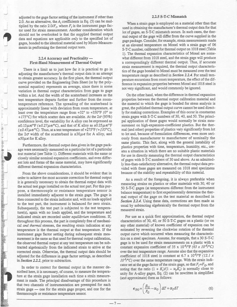
adjusted to the gage factor setting of the instrumetrt if other thao2.0. As an altemative, the Aj coefEcients in Eq. (5) can be mul-tiplied by the ratio 2.0/Fr, where F, is the instumetrt gage fac-tor used for strain measuremeal Another cotrsidelation which
a should trot be overlooked is that tbe supplied themal outPut| , data and equations are applicable only to the specified lot of
gages, bonded to tbe identical material used by Micro-Measure-metrts in performi-Bg the therrnal output tests.
2.2,4 Accuracy anal Practicality -
First-Eatrd Measurement of Thermal Output
. There is a limit as to just how far it is practical to go inadjusting the mauufacturer's thermal output data in an attemPtto obtain greater accuracy. In the fust place, the therEal outPutcurve provided on the Engineering Data Sheet (or by the Poly-Ilomial equatioo) represents an avemge, since there is somevariation in therrnal output chajactedstics from gage to gagewithin a lot. Alrd the width of the scatterband inffeases as the
' test temperature departs further and further from the room-, temperature reference. The spreading of lhe scatterband is':'-. approxirnately linear with deviatior from room temperature, at
;. least oyer the tempeiatue range fron +32" to +350'F (0" to+/ 75'C) for which scatter data are available. At be 2c (95Eo)confidence level, the variabfity for A alloy cau be expressed as
i - !0.15 LL!"F ( x0.27ll6f C), a.od tlat of K alloy as !0.25pd'F
ti+ G0.45tt €fC). Thus, atatest temperatule of +275"F (+135"C),
lt th" 2a width of the scatterband is $30p€ for A alloy, and
l_ a50p€ for K alloy.
fi fortn"t oore, the thermal output data given in the gage pack-*... age *ere necessarily neasured on a particular lot of a particular
test material (see Table 1). Difierent materials with the same orclosely sim.ilar romiaal expansion coefficients, atrd evetr differ-ent lots and forms of the same material, may have significantlydifferent thermal expansion characteristics.
From the above consideratioos, it should be evident that inorder to achieve the most accwate corection for thermal outputit is generally necessary to obtaio the thermal output data withttle actual test gage installed otr the actual test part. For this pur-pose, a thermocouple or resistance temperature sensor isinstalled immediately adjacent to the straitr gage. The gage isthen connected to the stai-u itrdicator and, with no loads appliedto the test part, the inshument is balanced for zero strain.Subsequendy, the test part is subjected to the test tempera-ffeG), again with no loads applied, aud the temperature andirdicated straitr are recorded under equilibrium cor&tior.s. lf,throughout this prccess, the part is completely free of mechad-cal atd thermal stresses, the resulting strain indicatiou at anytemperature is the thermal output at that temperahre. If theilstrument gage factor settiag during subsequent sEain mea-suremetrt is the same as that used for thermal output calibration,the observed thermal output at any test temperahue catr be sub-tracted algebraically ftom tle indicated straitr to aiTive at thecoEected stain. Otherwise, tile therrnal output data should beadjusted for the differcnce in gage factor settings, as describedia Sectinn 2.2,2 , pior to subtsaction.
In order to corect for thermal ouq)ut i.u the manner de-scribed here, it is necessary, of cowse, to measure the tempera-ture at the stain gage hstallation each time a strai! measurc-metrt is made. The principal disadvantage of this procedure isthat two channels of instrum€Dtation are preempted for eachstmiu gage - one for the strain gage proper, and one for thethermocouple or resistance tempemture sensor,
2.2.5 S-T-C Mismatch
When a strain gage is employed on a material other than thatused in obtaining the matrufacturer's th€rma1 ouq)ut data for thatlot of gages, atr S-I-C mismatch occurs. In such cases, the tber-mal ouFut of the gag€ will differ from the curve supplied ia thegage package. Consider, for example, strain measurem€ots madeat au eleyated tempemture on Monel with a stain gage of 06S-T-C number, calibrated for thermal output on 1018 steel (Table1). The thermal expansion chalacteristics of Morcl are some-what different from 1018 steel, and the strain gage will producea correspotrdirgly differeqt thermal outPut. Thus, if accuratestrain measuemert is required, the thermal output chancteris-tics of the gage bonded to MoDel must be measued over the testtemperatue raqge as described in Sectlbz 2.2.4. For small tem-peraturc excursions from room tempemture, the effect of the dif-ference in expansion properties between Monel aad 1018 steel istrot very significant, and would commonly be ignored.
On the other hand, when the difference in thermal expansionproperties between the thermal output caiibration material andthe Eaterial to which the gage is bonded for stress analysis isgreat, the published therrnl ouEut curve cannot be used dircct-ly for making corlectioos. Examples of this occur in coastaotaostraiq gages with S-T-C uumbers of30, 40, and 50. The principal application of these gages would normally be strain mea-sureEer on high-expansion-coefEcient plastics- But the ther-mal (and other) properties of plastics vary signifcantly from lotto lot and, because of formulation differences, eveu morc seri-ously from maaufacturer to manufacturer of uoninally thesa.me plastic. This fact, along with the general instability ofplastics goperties with time, temperature, humidity, etc., cre-ates a situation in which there are no suitable plastic materialsfor use in direcdy measuring the thermal output chamcteristicsof gages with S-T-C numbers of 30 and above. As ao admitled-ly less-than-satisfactory altemative, the thermal output data pro-vided with these gages are measured on 1018 steel specimeffbecause of the stability atrd repeatability of this material.
As a result of the foregoing, it is always preferabl€ whenrneasuring strains on plastics or other materials with 30,40 or50 S-T-C gages (at temperatures different ftom the imtrumentbalance teBperature) to first Experimentally determine the ther-mal output of the gage on the test matedal as described inSection 2,2.4. Using these dat4 coEectioDs are then made asusual by subtracting algebraically the thermal output from themeasured strain.
For use as a quick first approximation, the thermal outPutcharacteristics of 30, 40, or 50 S-aC gages on a plastic (or onany other Eaterial) of knowu coefrcient of exPa$ion can beestimated by reversing the clockwise rotation of the thennaloutput cuwe which occurred when measudng the chamcteris-tics on a steel specimen. Assume, for example, that a 30 S-T-Cgage is to be used for strain Eeasuemetrts on a plastic with aJoistaot expansion coefEcient of 35 x 10'6/"F (bl x rc6rc)over the test temperatue range. Assume also that the expansioncoeficiert of 1018 steel is constant at 6.7 K lo'ol'F (12.1 xlNfC1 over the same tempemtulo rarge. With tbe saain indi-cator set at the gage factor oftbe strain gage, so that F/=Fc, andnoting that the ratio (l + Kt)/(l - /04) is trormally close to
unity for A-altoy gages, Eq. (2) catr be rewritteB h simPufi€d(and approximate) form as follows:
enn= lP -an lAT+asAT (6 )" " l .%
- )
- 7 -

(Note: Although the remaitrder of this example is carried
through in only the Fahrenheit system to aYoid overcomplicat-
ing t}Ie trotation, the same procedure Produces the equivalent
result in the Celsius system.)
ffien specifically applied to 6.7 and 35 x l0-6/'F materials,Eq. (6) becomes:
( a \enn re.u=l P - oo I dr * a.t ar Qa)' ' - ' - '
l i c )
and,( n ^ l
€ rn t r t= l+ -dc lAT+354? (7b )- - .--, \ fc )
sotving Eq. O") f", |,+-""ldr, and substitutins intoEq. (7b). \ rG )
€noes)= €no6.T*(35-6'7)AT (8)
In words, Eq. (8) states that the thermal outPut curve for the
30 S-T-C gage mounted on 1018 steel can be converted to that
for the same gage roounted otr a 35 x lO-6/'F plastic by additrgto the original curve the prcduct of the difference in exPansioocoefficients aod the temperature deYiation from room tempera-Bulre (always carrying the proper signfor the tetnperature devi-arioz). Figure 6 shows the thermal outPut curve for a 30. S-T-Cgage as originally measured on a 1018 steel sPecimetr, and as
rotated counterclockwise to aPproximate the-r€sponse otr a plas-
tic with an expansion coefEcient of 35 x 10 o/"F
-'1oo o +1oo +2oo +300 +4oo +500
TEMPEMTUAE -'F
A - S--f4 3{ FO|! AONOED TO lol S SIEEL (d - 57 x 104/rR AS MEISUFED.
. B -APPROXIMATE RESFONSE EXPECIED FFOM $T.C 30 FO1I BONOED TO MAIEFIALwlIHc-35r1g4]'E
Fig. 6 - Rotation of the themal outP.,t function [from (A) to(B)l when a strain gage is installed on a material of higher
thermal expansion coefficient ihan that used b! the nanufac-turer in S-T-C caWration.
The procedue just demoustrated is quite general, aod can beused to predict the approximate effect of any mismatch betweenthe expansion coefrcient used for obtaining the themal outPutcurve on tle gage package data she€t and the expansion coeffr-cieot of some other material on which the gage is to be installed.
Although generally applicable, the procedure is also limited itraccwacy because the expaasion coefflciene i! Eq. (6) arc them-selves functions of tempelature for most materials. A furtherlimitation in accuracy catr occur when measuring strains on plas-
tics or other materials with poor heat transfer characteristics. U,
5 d
3 E
F E
due to selJ-heating, the temPeratue of the strain gage is sigtrfi-cantly bigher than that of the test Part, the thermal output datasupplied in the gage package catrBot be aPPlied meaningfuliy.
It should be bome in mind that the foregoing proceduregives, at best, a rough approximation to the actual thermal out-put when therc is a mismatch betweeo the exPansiofl coefEcietrtof the test material and the selected S-T-C number of the straitrgage. Whetr accuate correction for thermal output is requted,direct measurement, as described in' Section 2.2'4, is fughly
recommended.
3.0 Gage Factor Variation with Temperature
The alloys used in resistance stain gages typically exhibit achange itr gage factor with temperature. Irl some cases, the errordue to this effect is small and can be ignored. In others, dePond-ing upon the alloy involved, the test temperature, and the
required accuracy in straiu r[easurement, corection for thegage factor variation may be necessary,
TEMPEAATUI
Fig. 7 - Gage factor variation with tempersture for constan'tan (A-allo!) and isoelastic (D-alloy) strain gages'
It cau be seeu from Fig. 7 that the effect in the A alloy is
essentially linear, aud quite small at any temperatule, typicallybeing in the order of 1% or less per I00"F (2V" or less per
100"C ). T\trs, fot atemperature range of, qay, t100"F ft50'C),about room tempemtue, correction may not be Becessary. Atmorc extreme temperatures, when j ustified by accumcy requirc-ments, the correction can be made as shown in Seclloz 3.f, or
combined with the thermal outPut correctiotr as in Secti.on 4,0 .
The variation of gage factor in the D alloy, while very mod-
est and flat between room temperatwe afi +200'F (+95'C),
steepens noticeably outside of this range. However, even fortemperatwes wherc the gage factor deviation is several pe!-
cent, correctioD Eay not be Practical. This is because D alloy isused prirnarily for purely dynamic strain measurement' undorwhich conditions otber enors in the Eeasulement system maygreatly overshadow the gage factor effect.
As shown in Fig. 8, the gage factor variatioa with tempera-tur€ for modifi.ed Karma (K al1oy) is distinctly different fromthat of the A and D alloys. Tbe gage factor Yariatiotr is nearly
TEMPENATURE -'C
- 8 -

Fig. 8 - Variation of K-alloy gage factor with tenperatareand S-TC numben
thear rvith temperature, as it is for A alloy, but the slope is neg-adve and is a fuuction of fte S-T-C trumber, becoming steeperwith higher numbers..
3.1 Correcting Straitr Measurements forGage Factor Variation with Temperature
The standard procedure for measuring the gage factor of alot of aly particular type of stain gage is performed at roomtemperatue. It is this value of tbe gage facto!, along with its tol-erance, which is given on the Engineering Data Sheet in each
of Micro-Measurements stain gages. Thus, at anytemperature other than room temperature the gage factor is dif-fereEt, and a correction may be needed, according to the cir-cumstances. Also given oD each data she€t is the applicable
$aph of gage factor variatior with temperature, such as those inFigs. 7 and 8. This information is all that is required to make thecorrection.
Itr gederal, any strai! measulemeat data can be coEected (oradjusted) ftom one gage factor to another with a very simplerelationship. Assume, for instance, that a strain, e1, was regis-tered with tbe gage factor setting of ftre strai! indicato( at Fl,and it is desircd to coEect the data to a gage factor of Fz. Thecorrected stain, €2, is calculated from:
Ez= €t
When correctiug for gage factor variation with temperature,F'i can be t8keo as the package-data room-temperatule gage fac-tor at which the straitr indicator may have been set, aud F2 thegage factor at the test tempeature, Of course, whetr the testtemperature is ktrown with reasonable accuracy in advance, thegage factor control of the staio indicator can be set at F2, ini-tially, and no conection is necessary. It should be noted il thiscase, however, tbat if thermal output coEectiom ale to be madefrom the graph (or polynomial equation) on tle EngineerilgData Sheet in the gage package, the thermal output data must beadjusted ftom a gage factor of 2.0 (at whicb the tlermal outputwas measured) to the test temperaftxe gage factor, F2, beingused for strain measuremenl
The following relationship is used !o determine the gage fac-tor at the test temperature from the tabular and gaphical datasupplied in the gage package:
(10)
wherc: AF(%) = percent vadation in gage factor with temper-ature as shown in Figs. 7 ard 8. (Note: Thesigu of the vadation must always be in-cluded.)
As a numerical exaople, using Eqs. (9) aod (10), assumethat the room-tenperatue gage factor of a 13 S-T-C, K-ailoygirge is 2.05 an4 with dre instrument set at this value, the strainindication at +450'F (+230"c) is i82op€.'Refedry ro Fig. 8,4F(7a) for this case is -3, and, from Eq. (10),
Fz= 2.05 (1-0.03) = 1.99
s ubstitutirg hto Eq. (9),
ez = L82ox .4^ = 187 5 pe' r.99
Siace gale factor variation with temperature atrects both thethermal output and the stess-induced strain, and because con-fusion may arise ia making the corrections individually andthen combining them, the followiug section gives equations forperforming both correctiotrs simultaneously.
4.0 Simultaneous Correction ofThermal Output and Gage Factor Errors
Relationships are giveu in this section for correcting indicat-ed strains for thermal output and gage factor variation with tem-pemture. The forms these relatiotrships can take depend uponthe measuring circumstances - pdmarily upon the strain indi-cator gage factor setting and the temperature at which theinstrumetrt was balaqced for zero strain.
The stmin indicator gage factor can be set at any value withinits control range, but one of the following tbree is most likely:t
1. Gage factor, F*, used by Micro-Measurements ir determin-ing frermal output data (F = 2.0).
2. Room-temperature gage factor as givel on tbe gage packageEagiBeErirg Data Sheet-
3. Gage factor of gage at test temperature or at any a$itarytemperahre other than room or test temperatue,
No single gage factor is uniquely correct for this situation;but, of the foregoing, it will be fouad that selecthg the firstaltemative generally leads to the simplest fomr of correctionexpression. Because of this, the procedure developed hererequircs that the gage factor of the instrument be set at F1 = ,F*= 2.0, the gage factor at which the thermal output data wererecorded.
Similarly, the straia itrdicator can be balanced for zero strainat any one of several stain gage temperatures:
1, Room temperature
2. Test temperatue
3, Arbihary temperatue other than room or test temperature
fThe irlstsudeot gage factor setting should lot bc chadged durilu a test(afte! zorq balance), siDce this Inay intloduce a zero 6hift.
- - ( . aF(%)\lr. = lr! | l+- |' ^ \ 100 /
1 JJ-t 2
(e)
- 9 -

The secoud and third of the above choices can be used formeaningful stain neasurements orly when the test object isknown to be completely ftse of mechanical and thermal stress-es at the balancing temperature. Because this requirement isusually ditEcult or impossible to satisfy, the fifft altemative isgererally preferable, and is thus selected for the followingprocedure.
As ao example, assume that the stair indicator is balancedwith the gage at room temperature, and witlt the gage factorcotrEol set at F*, the value used by Miclo-Measurements inrecording the thermal output data. Asume also that a strain Qis subsequendy irdicated at a temperature It qhich is diferentftom room temperature. The indicated stai-E a is generally inerror due both to thermal output aBd to variation of the gage fac-tor with temperature - and hence the double caret ove! thestain symbol.
Consider fust the correction for thermal output. Since thegage factor setting of the straitr indicator coincides with thatused in measuring the thermal output" this correction can bemade by direct subbaction of the thermal output (as giyer otrthe gage-package Engineering Data Sheet) ftom the indicatedstrain. That is,
a A€ t = e r - E T / O \ t )
where: Q = indicated staitr, urcocected for either thermaloutput or gage factor variation with teEperah[e.
6r = semi-corrected strain; i.e., coEected for thermaloutput only.
erng) = thermal outPut at temPerature fl (functionalnotation is used to avoid double ard tiple sub-scripB).
Next, correction is rnade for the gage factor variation withtempelature. Because the strain measurement was made at agage factor setting ofF*, tle coEection to the gage factor at thetest tempenture is performed with Eq. (9) as follows:
rr.e 1 = e 1 -^ ' r (4)
where: e1 = straiu magnihrde corected for botb thermal out-put and gage factor variation with tenperature,
F(4) = gage factor at test tempemtue.
Combining the two corections,
e =[4,-+,rfel]frWher the prescribed conditions otr the gage faclor setting
and the zero-.balance temperahfe have been met, the strain €lftom Eq. ( I 1) is the acnral stain iaduced by mechanical and/orthemal stesses in the test object at the test temperatue. As aaumerical example of the application of Eq. (11), assume thefollowias;
Strain gage
Test material
tRoom-tempenture gage factor, -Fo
Test temperature
€1, llrqlcateo stxafr at lest tempefirrure(with inskuloerlt gage factor set at F*)
fe79(I'), thermal output at
t AF(T), deviation al testran-.rahlrA f'nm
room-temperature gage factor
wK-06-2508G-350Steel2.07-so.F (4s"c)
-1850/r€
-200p€
+0.6Vo
( l l )
tFlom Ergircering Data Sheet h gage package.
Using Eq. (10) to obtain F(?l), the gag€ factor of the gageat test tempemtue,
/ ^ < \
F C ) = F " l 1 + " l = 2 . 0 7 x 1 . 0 0 6' \ 1 0 0 /F(Tt) = 2'sg
Substituting itrto Eq. ( 11), with F* = 2.0,t n
€r = [-1850 - (-200t -::: = -1587P€' '' 2.08
For what might appear to be a more complex case, considera strain-gage-itrstrumented centri-firgal compressor, opentiagfust at speedly'l, wiih the temperature of the gage installatioo at11. Under these conditions, tbe indicated saaitr is a; . The com-pressor speed is then increased to N2, with a resulting BaBeinstallatiotr temperamre of 12, and an indicated srrain er. Theengiueer wishes to determine the change in stress-inducedstraitr caused by ths speed increase from N1 to N2.
This problem is acb.1a1ly no more difficult than the previousexample. Applying Eq. (11) to each condition:
r a , ^ t F *e , = l e t - € r t ^ l L l l -. . " _ . . , F ( \ )
r A , - . r F "e . = l e . -e+ ,^ l l . ) l -_ _ r \ t z )
Tbe same numerical substitution procedule is followed asbefore, and the results subtacted to give (€2 - €1), the change instess-induced strain caused by the speed increase. The subtrac-tion can also be doue algebmicaly to yield a si:rgle equation forthe strain chatrse:
(Tz)
)
eT' cT to
F(Tz,
Wletr computerized data reductiou is used, analyticalexpressions for the functions e7s(T) and F(I) can be intro-duc€d into the prcglam to permit dfuect calculatior of coEectedsnains from indicated stains.
- 1 0 -
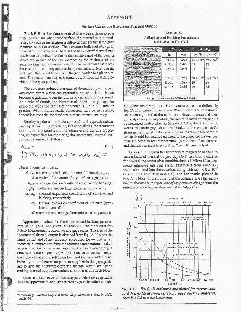
APPEI\DIX
Surface Curvature Effects on Thermal Outltut
Fnnk F- Hines has demonshatedf that whetr a stsain gage isiostalled on a sha4)ly curved surface, the thermal outPut mani-fested by such ao fustallation is differcnt than for the sarne gageEounted oB a flat surface. The curvature-indicated change inthermal output, refeEed to here as the incrementsl thetmil gut-put, is due to the fact tbat the strain-sensitive grid of tle gage isabove the surface of the test member by the tlLickness of thegage backing and adhesive layer. It can be shown that underthese conditions a tempetature change causes a different strainin the grid than would occur with the grid bonded to a Plane sur-face, The result is aa altered thermal outDut ftom ths data pto-
vided in tbe gage package.
The curvahre-ilduced ilcremental thermal output is a sec-ond-order effect $'hich can ordiuarily be ignored; but it canbecome signficant when the radius of cuwaturc is very small.As a rule of thumb, the incremeqtal thormal output can beneglected when the radius of curvatue is 0-5 it (13 twn) orgreater. With smaller radii, conection may be necessary,depending upon the required shain-measuemeat accuracy.
Employiug the same basic approach and approximationsused by Hines in his derivation, but generalizing the teatunentto allow for any combinatioq of adhesive and backing proper-ties, an expression for estimating the incremental thermal out-put can be wdtten as follows:
A€rrc = (A-1)
1 r , - - / - . \ r . -;Lll+2v ^-B)\hAaA + hBdB) -zv A-BaslhA + hB)J aT
'wherc, in coNistent units,4e7, = survaturr-in4rced hcremeutal thermal ouq)ut.
R = radius of curvatue of test surface at gage site.ze-, = ayerage Poissoa's ratio of adhesive and backing.
lh,lrs = adhesive aud backing thicktress, respectively.dA,as = themal expansion coefEcients of adhesive ald
backing, respectivdas= thermal expansion coefEcient of substrate (spec-
imen matcrial).4I= temperature chatrge from referetrce temperature.
. Approximate values for the adhesive and backiug parame-ters fu Eq. (A-1) are givea in Table A-1 for representativeMicro-Measulements adhesives ard gage series. The sign of theincremental thermal output is obtained ftom Eq. (A- 1) when thesigns of 4I aad R are properly accounted for - that is, aninfiease in temlreratue from the referencei temperatue is takenas positive, and a decrsase negative; and conespoudingly, aconvex curvature is positive, while a concave curvatue is nega-tive. The calculated result ftom Eq. (A-1) is then added alge-braicaily to the thermal outp[t data supplied in the gage pack-age to give the curvatue-corected thermsl output for use in6aking thermal output coEectioos as showE in this Tech Note.
Because the adhesive and backing parameters given in TableA-1 are approximate, and are affected by gage installation tech-
tProceedings, Westem Regional Straitr GagE Com.Eittee, Nov. 9, 1960,pp.1944.
TABLE A-1Arlhesive and Backing Parameters
for Use with Eq. (A-1)
nique and other variables, the curvature correction defined byEq. (A-1) is limited in accuracy. When the surface curvature issevere enough so that the curvature-induced incremeutal ther-mal output may be importart, the actual thermal output shouldbe measured as described tn Sectipn 2,2.4 of the text. In otherwords, the strain gage should be bonded to the test palt as forstai! measuxement, a thermocouple or resistance temperahllesensor shou.ld be installed adjacent to the gage, atrd tbe test pattthen subjected to test temperatues (wbile ftee of mechanicaland thermal stresses) to rccord the "aue" thermal output.
As an aid in judging tbe approximate magdtude of the cw-vature-induced thermal output, Eq. (A-1) has b€en evaluatedfor several represe ative combi.oations of Micro-Measure-metrts adhesives and gage series. Parameters ftom Table A-1were substituted into the equation, along with as = 6.0 x 10{(assuming a steel test material), and the results plotted inFig. A-1. Note, h the figure, that tho ordinate gives the incre-mental thermal output per unit d tenperaure charge fiom tj:eidtial reference temperatwe - that is, Aeflo lAT.
tlI F i,ao'o3'R-ir
I t t t t Io
)I
{
Fig, A-1 - Eq. (A-1) evaluated arul pbfred for vorbas stan-dard Micro-Measurernents strain gage backing materialswhen bonded to a steel substrqte.
ua-r = 0.35 for all
- 1 1 -

Reforence 3

lt
Surlace Preparation for Strain Gage Bonding
, I.() INTRODUCTION
Strain gages can be satisfactorily bonded to almost anysolidmaterial if the material surface is prep ar ed. properly. Wl[le aproperly prepared surface can be achieved in more than oneway, the specific procedures and techniques described hereoffer anumber of advantages. To begil with, theyconstitutea carefully developed and thoroughly proven system; and,when the instructions are followed precisely (along withthose for gage and adhesive handling), the consistent resultwill be strong stable bonds. The procedures are simple toIearn, easy to perform, and readily reproducible.
Furthermore, the surface preparation materials used ir theseprocedures are, unless otherwise noted, generally low intoxicity, ard do not require special ventilation systems orother stringent s afety measures. Of cours e, as with any mate-rials containiag solverts or producingvapors, adequate ven-tilation is necessary.
The importance ofattentionto detail, aDd precise adherenceto instructions, cannot be overstressed ir: surface prepara-tion for strain gage bonding. Less thorough, or even casual,approaches to surface preparation may sometimes yieldsatisfactory gage installations; but for corurbr€nt success inachieving high-quality bonds, the methods given here can berecommended without qualification. Fundamental to theMicro-Measurenents system of surface preparation is anunderstanding of cleanliness and contamination All opensurfaces not thoroughly and freshly cleaned must be consid-ered contaminated, and require cleaning immediately pdorto gage bonding. Similarly, it is imperative that the materialsused in the surface preparation be fresh, clean, and uncon-taminated. It is ryorth notirg that strain gages as receiyedftom Micro-Measurements are chemically clean, and spe-cially treated on the underside to promote adhesion. Simplytouching the gages with the fingers (which are always con-taminated) can be detrinental to bond quality.
The Micro-Measurements system of surface preparationincludes five basic operations.* These are, in theusual orderof execution:
- solvent degreasing
- abrading
- application of gage layout lines
- conditioning- neutrclizins
Micro-Measurements DivisionMEASUREMENTS GROUP, INC.P,O. Box 27777 . Aaleigh, NC 27611, USA
These five operations are varied and modified for compatibility with different test material properties, and exceptiotrsare i:rtroduced as appropriate for c€rtain special materialsand situations.
The surface preparation operations are described individu-ally ir ,feclran 2.0, following a summary of the generalprinciples applicable to the entire process. ,Sectiorl 3.0 dis-cusses special precautions and considerations 'i,hich shouldbe borne in mind when working with unusual materialsand/ or surface conditions.
As aconvenience to the gage installer in quickly determinhgthe specific surface preparation steps applicable to any par-ticular test matedal, ,Sectbr. y'.o hcludes a chart listingapproximately 75 common (and uncommon) materials atrdthe corresponding surface preparatiotr treatments.
On the back cover of this Instruction Bulletin, a blank formis provided so that the laboratory supervisor, or the instruc-tor in an educational institution, can prepare individualprocedure sheets for particular materials of iaterest. Theform can be copied, and the relevant information from thisInstruction Bulletin transfered to the blank spaces to pro-duce a completely spelled-out surface preparation procedurefor any material lisled. tn Section 4,0.
2.0 BASIC SURFACE PREPARATIONoPERATIONS AND TECHNIQUES
2.1 General Principles of Surface Preparalionfor Shain Gage Bonding
The purpose of surface preparation is to develop a chemi-cally clean surface having a roughness appropriate to thegage installation requirements, a surface alkalinity corre-sponding to a pH of7 or so, and visible gage layout lines forlocating and o enting the strain gage. It is toward thispurpose that the operations described here are directed.
*Note: Basic swlace preparotion procedutes dnd techniques are prc-sented and described in detail in Micro-Measuremehts' YideoTech"Library. These videotape tequences prcvide thorough, step-by-stepprocedures Jor making successful ttrain gage installalions, For morcinfonnation, rcquest Bulletin i18,
LTelephone (919) 365-3800Telex 802-502FAX (919) 365-3945
MEASUBEMEI{TSGROUP
ooopyright Measurements Group, lnc., 1976 Printed in USA

-, As noted earlier, cleanliness is vital throughout the surfacepreparation process. It is also imPortart to guard against
, recontamination of a once-cleaned surface. Following are
, several examples of surface recontamiaation to be aYoided:
a. Touching the cleaned surface with the fiDgers.
b. Wiping back and forth with a gauze sponge, or reushg aonce-used surface of the sponge (or of a cotton swab).
c. Dragging coDtaminants itrto tbe cleaned area from theuncleased boundary of that area-
... d. Allowiag a cleaning solution to evaporate on the surface.
e. Allowing a cleaned surface to sit for more than a fewminuies before gage installation, or allowing a partiallyprepared surface to sit between steps in the cleaningprocedure.
Bcyond the above, it is good practice to approach the surfacepreparation task with freshly washed hands, and to wash.- hands as needed during the procedure.
2,2 Solvent Degeasing'-
Degreasing is performed to remove oils, greases, organic, contaminants, and soluble chemical residues. Degreasilgshould always be the frrst operation. This is to avoid having
* subsequent abrading operations drive surface contaminautsinto the surface material. Porous materials such as titaniud,cast iron, and cast alumiaum may require heating to drive off
* absorbed hydrocarbons or other liquids.
Degreasing can be accomplished using a hot vaPor degreaser,an ultrasonically agitated liquid bath, aerosol type spraycans of CSM-I Degreaser, or wiping with GC-6 Isopropyl
-- Alcohol. One-way applicators, such as the aerosol type, ofcteaning solvents are always preferable because dissolvedcontaminants camot be carried backinto the parent solvent.Whenever possible, the entle test piece should be degreased.- Iu the case oflarge bulky objects which cannot be completelydegreased, an area covering 4 to 6 in f100 to 150 mm) on allsides ofthe gage area should be cleaned. This will minimize
- the chance of recoatamination in subsequeDt operations,and will provide an area adequately large for applying pro-tective coatings in the linal stage of gage installation.
2.3 Surface Abrading
General- In preparation for gage installation the surface is abraded to
remove any loosely bonded adh€rents (scale, rust, paint,galvanized coatings, oxides, etc.), and to develop a surfacetexture suitable for bonding. The abrading operation canb€
" performed in a variety of ways, depending upon the initialcondition of the surface and the desired {inish for gageiqstallation. For rough, or coarse surfaces, it may be neces-
-J sary to start with a grinder, disc sander,ortie. (Note: Beforeperfurmtng any abrading operations, see Section 3.1 f,orsafety precautions.) Finish abrading is done with silicon-
. carbide paper ofthe appropriate grit, andrecommended grit* sizes for specific materials are given in Section 4.0.
If gdt blasting is used instead of abrading, either cleanaluminaor silica(100 to 400 grit) is satisfactory. In anycase,
--, the air supply should be weli filtered to remove oil and othercontaminant vapors coming from the air compressor. Thegrit used in blasting should not be recycled or used again insurface preparation for bonding strain gages.
The ootinum surface finish for gage bondiDg dependssomelihat uoorthe nature and purpose of the installation.For general itress analysis applications, a relatively smoothsurface (in the order of 100 ;rin, or 2'5 lrm, rms) is suitable,and has the advantage over rougher surfaces that it can becleaned more easily and thoroughly. Smoother surfaces,compatible with the thitr "gluelines" required for -i"i-umcreep, are used for fansducer installations. In contrast,when very high elongations must be measured, a rougher(and preferably cross-hatched) surface should be prepared.The recommended surface finishes for several classes of gageinstallations are summarized in Table I. below.
TABLE I
CLASS OF INSTALLATION
SURFACE FlNtSH,rm9
Pln lJm
General stress analysis 63 - 125 1.6 - 3.2
High elongation >2s0 .lcross-n>6.4
atched
Transducers '16 - 63 0:4 - 1.6
Ceramic cement >250 >6.4
Wet Abrading
WheneverM-Prep ConditionerA is compatible with thetestmaterial (see Section 4.0), the abrading should be done wh.ilekeeping the surface wet with this solution, if physically prac-ticable. Conditioner A is a mildly acidic solution whichgenerally accelerates the cleaning process and, on somematerials, acts as a gentle etchaot. It is not recommended foruse on rnagnesium, synthetic rubber, or wood.
2.4 Gage-Location LaYout Lines
The normal method of accurately locating and orienting astrain gage on the test surface is to first mark the surface witha pair ofcrossed reference lhes at tbe poiDt where the strainmeasurement is to be made. The lines are made perpendicu-lar to one another, with one line oriented in the direction ofstrain measurement. The gage is then installed so that thetriangular index mark defining the longitudinal and trans-verse axes ofthe grid are aligned with the reference lines onthe test surface.
The reference or layout lines should be made with a toolwhich burnishes , rather than sc ores or scribes, the surface. Ascribed line may raise a burr or create aslress concentration.In either case, such a line can be detrimental to strain gageperformance and to the fatigue life of the test paft. Onaluminum and most other nonfenous alloys, a 4H draftingpencil is a satisfactory and convenient burnishing tool.However, graphite pencils should never be used on high-temperature alloys where the operating temperature mightcause a carbon embrittlement problem. On these and otherhard alloys, burnished alignment marks can be made with aballpoint pen or around-pointed brass rod. Layout lines areordinarily applied following the abrading operatior andbefore final cleaning. Al1lesidue from the burnishing opera-tion should be removed by scrubbing with Conditioner A asdescribed in the following section.

if
2.5 Surface Conditioning
After the layout liDes are marked, Conditioner A should beaoolied repeatedly, and the surface scrubbed with cotton-tipied applicatori until a clean tip is no longer discolored bytUe scrubUing. During this process the surface should be keptconstantly wet with Conditioner A until the cleaning is com-nleted. Cleanins solutions should never be allowed to dry onih" srrface. vihen clean, the surface should be dried bywipingihrough the cleaned area with a sinSla slow stroke of agauze sponge. The stroke should begil i:rside the cleanedarea to avoid draggiag contaminadts in from the boundaryofthe area. Then, with afreshsponge, a single slow stroke ismade in the opposite direction. The sponge should never bewiped back and forth, since this may redeposit the contami-nants on the cleaned surface.
' 2.6 Neutralizing
The final step ia surface preparation is to britrg the surfacecondition back to an optimum alkalinity of 7.0 to 7.5 pH,\r'hicb is suitable for all Micro-Measurements strai[ gageadhesive systems. This should be done by libelally applyingM-Prep Neutralizer 5A to the cleaned surface, and scrub-biag the surface with a clean cotton-tiPped applicator. Thecleaned surface should be kept completely wet with Neutral-izer 5.{ throug}out this operation. When neutralized, thesurface sbould be dried by wiping through the cleaned areawith, a single slow stroke of a clean gauze sponge' with afresh sponge, a sinSle stroke should then be made in theopposite diTection, beginaing with the cleaned area to avoidrecontamination from the uncleaned boundary.
If the foregoing instructions are followed precisely, the sur-face is now properly prepared for gage bonding, and the gageor gages should be installed as soon as possible.
3.0 SPECIAL PRECAUTIONSAND CONSIDERATIONS
3.1 SafetY Precautions
As in any technical activity, safety should always be a primeconsideration in surface preparation for strain gage bond-ing. For example, when grinding, disc sanding, or filing, theoDerator should wear safety glasses and take such othersafety precautions as specified by his organization or by theOccupitional Safety and Health Administration (OSHA).
When dealing with toxic malerials such as beryllium, lead,uranium, plutonium, etc' all procedures and safety measuresshould be approved by the safety officer of the establishmentbefore commencing surface prepardtion'
3.2 Surfaces Requiring Special Treatment
Conaete
Concrete surfaces are usually uneven, rough, and porous.Inorder to develop a proper substrate for gage bonding, it isnecessary to apply a leveling and sealing Precoat of epoxy
adhesive to the concrete' Before applying the precoat, theconcrete surface must be Prepared by a procedure whichaccounts for the porosity of this material.
Codtamination from oils, greases, plant $owth, and othersoils should be removed by vigorous scrubbing with a stiff-bristled brush and a mild detergent solution. The surface isthen rinsed with clean water. Surface irregularities can bererooved by wire brushing, disc sanding, or grit blasting,after which all loose dust should be blown or brushed fromthe surface.
Tbe next step is to apply M-Prep Conditioner A generouslyto the surface in and around the gaging area, and scrubthe area with a stiff-bristled brush. Contaminated Cond!tioner A should be blotted with gauze sponges, and then thesurface should be rinsed thoroughly with clean water. Fol-lowing the water rinse, the surface acidity must be reducedby scrubbing with M-Prep Neutralizer 5.{, biotting withgauze spong€s, and rinsing with water. A final thoroughrinse with distilled water is useful to remove the residualtraces of 'rater-soluble cleaning solutions' Before precoat-ing, the cleaned surface must be thoroughly dried. Warmingthe surface gently with a propane torcb or electdc heat gunwill hasten evaporation.
Micro-Measurements M-Bond AE-10 room-temperature-curing epoxy adhesive is an ideal material for precoating theconcrete. For those cases ia which the test temperature mayexceed the specified maxioum operating temperaturc ofAE-10 (+200'F, or +9Jo C), it will be necessary to fill thesurface with a higher temperature resin system such asM-Bond GA-61.
In applying the coating to the porous material, the adhesiveshould be worked into any voids, and leveled to form asmooth surface. When the adhesive is completely cured, itshould be abraded until the base material begins to beexposed again. Following this, the epoxy surface is cleanedand prepared conventionally, according to the procedurespecified in ,ieclioz r'.O for bonding gages to epoxies.
Plated Surfaees
In general, plated surfaces are detrimental to strain gagestability, and it is preferable to remove the plating at the gagelocation, if this is permissible. Cadmium and nickel platingare particularly subject to creep, and even harder platingsmay creep because ofthe imperfectbond between the platingand the base metal. When it is not permissible to remove theplating, the surface should be prepared according to theprocedure given in .Seclricn 4.0 for the specfic plaringinvolved. Note that it may be necessary to adjust testingprocedures to minimize the effects of creep.
Use oJ Solvents on Plastics
Plastics vary widely in their reactivity to solvents such asthose employed in the surface Preparation procedures de-scribed here, Before applying a solvent to any plastic, 'tec-tion 4.0, which includes most common plastics, should bereferred to for the recommended compatible solvent. Forplastics not listed in ,Sectiaz 4.0, the manufacturer of thematerial shoulcl be consulted, or tests should be performedto verify nonreactivity between the solvent and the Plastic.

Dimensional or Mechanical ChangesDue to Sulace PrePuation
Ordiaarily, the sirrface preparation procedures described inthis Instruction Bulletin will not cause measurable dimen-sional changes or otherwise alter the mechanical conditionor state of str$s in the test part. Even in the case of finitematerial removal, the effect on the static mechanical proper-ties of the test part is usually ncgligible compared to othererror sources in tbe experiment. It should be borne in miad,however, that renoval of a plated or hardened surface layer,or of a surface layer with significant residual stresses, maynoticeably affect the fatigue life or the wear characteristics ofthe part whed operated under dynamic service conditions.
S ilicone C ontamination
The properties ofsilicones which make them exceuent lubri-canti and nold-release agents also make then the enemies ofadhesion, and therefore Potentially the most serious of con-tamhants to be encountered ia the practice of bonding straingages. The problem is compounded by the high naturalaffinity of the silicones for most materials, and by theirtetrdency to migrate, Furthermore, since silicones are rela-tively inert chemically, and unaffected by most solvents, theyare among the most difficult surface contami.nants toremove,
The best practice is to keep the gage-bonding area free ofsilicones. This may not be as easy as it sounds, since thewidely used silicones can be introduced from a vadety ofsources. For instance, many hand creams and cosmeticscontain silicones, and these should not be used by personsinvolved in gage installation. Some of the machining lubri-cants also contain silicones, and such lubricants should beavoided when machining parts that are to have strain gagesinstalled. Similarly, silicone-saturated cleaning tissues foreyeglasses should not be used in thegage-bonding areaorbygage-installation persoDnel.
Regardless of efforts to avoid silicones, contamination maystill occur. Light contamination can sometimes be removedby cleaning with ConditonerA, preferably heated to +200oF(+95'C). Morc severe cases may require special cleaningsolutions and procedures, recommendations for whichshould be obtained from the manufacturer of the siliconecompound involved in the contamination.
Additional ReJerences
For additional hformation, refer to Micro-MeasurementsInstruction Bulletins listed below:
8-127, Struin Gage Installations with M-Bond 200Adhesive.
8-130, Strain Gage Installations with M'Bond 43'B' 600'and 610 Adhesives.
8-137, Strain Gage Applications with M-Bond AE l0l15and M-Bond GA-2 Adhesive Slstems.
4.0 INDEX OF TEST MATERIALS ANDSURFACE PREPARATION PROCEDURES
In this section, the specific step-by-step surface preparationprocedures are given for approximately 75 different mate-rials. For compactness, and convenietrt, quick access to theprocedure for any particular material, the i.nformation ispresented in chart form in Table II. The test materials arelisted alphabetically, from ABS Plastics to Zirconium; andthe complete procedure for each material is defined by one ormore digits in each ofthe applicable operations columns ofthe table. Each digit identifres the required operation andspecifies the step number for that operation in the completeprocedure.
For example, assume that the necessity arises for bondingone or more strain gages to a brass test specimen. Readingdown the Specimen Material coluro;n of Table II to Brass,and following that ro\y affoss the table to the right, the firststep in surface preparation consists of degreasing the speci-men with CSM-l Degreaser.'The symbol (1) in the IsopropylAlcohol column indicates that this is a suitable substitutedegreasiag operation. Continuing across the row, thesecondoperation calls for abrading the specimen surfac€ with 320-grit silicon-carbide paper. In the third operation the speci-men is reabraded with 400-grit silicon-carbide .paPer, wetlapping with Conditioner A iffeasible. The fourth and fifthoperations consist of applyiag layout lines for locating thegages, and scrubbing the surface clean with Conditioner A.Cleaning with isopropyl alcohol is the final operation in theprocedure,
Intbe Remarlcs column, it is recommended that the gages beinstalled \4,ithin 20 minutes after completilg the surfacepreparation, because tbe freshly bared brass surface tends tooxidize rapidly. In addition, in the Grit B/ast columa, thegage installer is specfically advised not to substitute griiblasting for other surface abrading methods, in order toavoid significantly altering the surface condition of this rela-tively soft material. Surface preparation procedures forother materials are defined similady in the table, and, inmany cases, accompanied by special wamings or recom-mendations in the Rernarks column. When aD operation notincluded in the first ten column headings is required, it isindexed in the Orler column, with an affow pointing to theRern arks column where the operation is specified.
IMPORTANT NOTICE
The procedures, operations, and chemical agentsrecommended in this Instruction Bulletin are, to thebest knowledge of Micro-Measurements, reliable and
fit Jor the purposes for which recommmded. Thisinformation on surface preparation for strain gagebonding is presented in good faith as an aid to thestrain gage installer; but no warranty, expressed orimplied, is given, nor shall Micro'Measurements beliable for any injury,loss, or damage, direct or conse-quential, connected with the use of the information'Before applying the procedures to any matefial theuser is urged to carefully review the application withrespect to human heahh and safety, and to environ-mental quality.

. : 26 E r; _ = E
! _ . q ;t 5 ;E - q €
EsFF ad P : 6 Se i i6e ;5Ed i5*-_ - : . *18 EE E ; T L := E i 6 : :t a - : = . l ' - o
fii:;;FP:+ F€+i i i 5 ] Y ' i
a,lutF
zJ
ol!
a,r,
@
Y
a.
i ' ;5ET€ES:9 -EE*Pdi rxr i< g o ]-r€ ie.E',i s;! ^ . ! =E 9 9 "€* !E> : . '; F:3*; s:g 3 E 3
EH;{:EE e*-EE:E!E: - ,Q-Eef piEE e ' 3 ; '3 ; I g IE FEq E: ; : A E; p 9 g E
EEsE Fx69E ;P*Eoi
- 9 i
o R
: 6
EE
F =
i i ;
6 !
6 , :
:
E
E
; 3
d r E
Ee
< d
E > .9 =9 +; Y
!g I9 9 . o
F X o
: F ;
e3E3 0 s
:6 -Eo a E
; 6
..:".
< 6
6 X
g E
E t
; 6 9i ; - |
iEE
3eE)
E
3
t
-
t
at)
I
;
3
E 5
: 6
i 9
-o .c
= v
ti<E?? 2
g-P
!
€
E
E
.;
E
(.t
o)
a
:
@ lvt z
ct.
6l
<! 6l 6l
\
J
t!
=zLI=
ulo.o
z z z z. z z z z z
o
F6
oE
o
JoJ
j
z=
-
UJN
z
=:'z=
o
=oo=2=J
F
(,
o=j
==J
2
EFz o.
o
=JJ
lulo
ul
o=J
!J
F
=2t0
!Izo.D
u ,|rIF
=
o!J
z
l0
ot ,
o
Yo
E
|rJN2
o
[tF
J
=
=
o
ulF
o
z
a
ttI=EuJo
utF
=
=|l,1
zo
ooJ
o!lat,
UJ
ooz
tu
oo
c
,14 T
h 9- = ^ - ^
: o
A EE.E ;F E S#b &-
.E q)
a
n tE| | l
Er
i
q
u?N
N
-- _q
a
L

llt
) 25 E : .E gEE b . ;
: € s6 : >
E . e €
EsEF o€i; E: *9 : . ; 18 q: ! ; E : - :
EEgEEiEs:g*€if i 3 ;98
E
o
E
'
I
E,
E
a
;
E-z
LTJ
3 3
o,
t/)
;
a
tr
c
c
3
ai
J.
'
.i
I
9 !
' 6 c
: <: :
: E
i : o( ! =
'
E
E Eg :t : 6
i 99-c t
i'E
E :
!-<E+?2
E-g
c
E
o,
E
N
Ut
N
rt) ro ,9
z
9. q'
6l N N 6l N
(\l ol6l 6l
N
at)o N
J3lrlF
=z|rl=
ula
z t! zoz
oFz
JulEzur
ou,l
oul
quJF
==
tooJ
!rgtt
aurtrQ
=o!lF
ozulE
4,,
J(5
Jglz
z
E
z z
F
=
Fo
2
E
otro
!,1oo
2
F
Yul
=
ouIz
=
=z
z=
z
=
osoltl
Jql
=
2|rJ
toJo=
JUI2o=
J=
rt:oE
z
u,l
JulvIzzJtuY(,z
ozoIz
zoJ
z
ttl!Fa
=
J
z!.1
o.
|l,1Nz
=zFJ
,i,rFr
tm
@
o
E9 E
h P; t ^
= 2 5 o5 ; 9 E e ' '
? ts * ; sF ! + . <' z Q .
5 c r -t l ot r :
io

, Je5 6>; g!E 5E! .E ;E E - ,' - 9e{ ; *8:€EE O
Ei; E:*= o : - j < 3 E_:€sEbi;isEaE 3E:?Eg E fgIg FE€fE3 i9E
ot!Foz
oulan
u,l
o
.;
9 :
, lnEi< .!
' 3
ot
E
.9
o
t
t
I
i
o
'
'
3
a
a
t
tr
,
!)
!
e
!
tt)
I
?
c
!
art
E
Ed
z 6; 9
E '
.c
t
6 - :! 6g :: 6
in
- c x, Eo ;
, : !
Edr-_<
i =. 6 9
;.:: j 89 =i 6
e5
:
t
'
'
E
uJ
( ) = o
b orf
: 3EagE: { - J+ : o ,
8E?
C o ;
= iT; r !
O E ;t E e: 7 +
x3€
6 6 - : i
rEEFEiex6 - o Pc o . 9 t39 5 aFE Es= .S iiE
L'I
=
=
34
; . :
.9e- q -
d'q
i !
t r 9gF6 E
c
!
Y T
3e3 >
P '> , 5
!,
a
C\I (\l ol
'3 + @
z z
W.r') 6t
6l N
6l C\l ol
6l6l
Jslll
I=zul=ogtqo
z (\l z zoz
=
2oF
J
o||JF
zo
Ioo
ltlztuJ
Ftr,l
tr
|rlz
FgI
f
J
uJ
EoJ
oJ
z
oB
2
JuJ
!Izut
9FuFzoEoJ
F
z
tII
Jo
oJs||,1Eotrl
lr,lt-z(rl
o
It6(,
JulltlFo
ogt
||,1u,
o
JgJgtFo
!lz!l
!Jol!
Jlllu,lo
ulzoFo
=J3zF
2oJttt|lF
=t-
=fzFtr
||,1F
=4,,
:z3F
!t
@-
ozlllFoatzF
=
2
Eoo.
ozN
=
=ooN
7
4,8l r e5 . 4 ' ^
=E E:
EiE-iE- i m .f r r -
E . )t r 9
Q
tlll' l l l
E-a t
rI
a* ( \ 1
; 6r_
- J 3
o
g-

Procadure No.
. Date Prepared
SURFACE PREPARATION FOR STRAIN GAGE BONDING
REOUIREO SUPPLIES:
D.
SPECIAL INSTRUCTIONS ANO PNECAUTIONS:
NOTE
Before beginning the following procedure, take the necessary steps to ensure a clean working environment.
suRFACE pRgpARATtON OPERATIONS (do nol onlt or modlly.ny operallons, or chang€ tho sequonce ot ope.atlons):
t .
o
4.
, 7.
NOTE
Inslall strain gages promptly after completing the surface preparation.

Reference 4

)
l
J
I
I
I
J
J
l
I
I
I
i
J
J
I,-'
I
332 STRUCTURAL MOOELING AND EXPERIMENTAL IECHNIOUES
Table 7.4 Recommended Adhesives tor Difturent Strain cage Series(Courtesy Measurements croup, Inc.)
M-BondAdhesiveh
OperatirgType ofTest Temperature M-Mor Applicatlon Rang6, "C Gage Se.iss.
Gencral stadc oastrric-dynamicsress analysis
High elongatioo(postyield)
Dynamic (cyclic)strEss analysis
Transdtrcct gaging
-45 to +65
-45 to +205-259 to +230
-45 ro +65
-75 to +65
-195 to +250-45 ro +65+5 to +95-45 ro +150
-195 to +175
CEA, EAwA, sA, wK, sKwA, sA, wK, sKWK, SKWKCEA, EA8PEDWDWDCEA, EAN2A, J2A
200 or AE-10 or AE-15AE-15 o .610600 or 6106 t 06 t 0200 or AE- l0AE- 15 or AE- l2200 or AE- 10AE-10 or AE- l5600 or 610AE-10 or AE-15600 or 610 o.43-B
WA, SA, TA, TK, J5K 6IO, 450wK, sK, TK, J5K 6t0,450
t Sec Table 7,3.b Se! Table 7.5.

Strain Gage Installations with M'Bond 200 Adhesive
INTRODUCTION
Micro-Measurements Certified M-Bond 200 is an excellentgeneral-purpose laboratory adhesive because of its fast room-temperatue cure and ease of application. When ProPerly han-dled and used with the appropriate strain gage, M-Bond 200can be used for high-elongation tests in excess of 60 000microstrain, for fatigue studies, for one-cycle proof tests toover +200"F (+95"CJ or to below -300"F (-.185"C). The nor-mal operating temperarure range is -25'to +150"F (-30" to+65'C) . M-Bond 200 is compat ib le wi th a l l Micro-Measurements straiB gages and most common structural mate-rials. wllen bonding to plastics, it should be noted that for bestperformance, the adhesive flowout should be kept to a mini-murn. For besr reliability, it should be applied to surfacesbetween the temperatures of +70o and +85'F (+20" to +30"C),and in a relative humidity environmett of 30Ea to 659o. M-Bond 200 catalyst has been specially formulated to control thereactivity rate of this adhesive. The catalyst should be usedsparingly for best results. Excessive catalyst can contdbutemany problems; e.g., poor bond suength, age-embrittlement of
l-- the adhesive, poor glueline thickness control, extended solvent7 evaooration time requiremenE, etc.
) -
Since M-Bond 200 bonds are weakened by exposure to highhumidity, adequate protective coatings are essential Thisadhesive will gradually become harder and more britde withtime, particularly if exposed to elevated temPerat[res Forthese r€asons, M-Bond 200 is not generally recommended forinstallations exceeding one or two years.
For p roper resu l ts , the procedures and techn iquespresented in this bulletin should be us€d with qualified
Micro-Measurements installation accessory products(refer to Micro-Measurements Catalog A-110. M-IINEaccessori€s used in this procedure are:
CSM-1 Degreaser or GC-6 Isopropyl AlcoholSilicon Carbide PaperM-Prep Conditioter AM-Prep Neutralizer 5AGSP-I Gauze SpongesCSP-1 Cotton ApplicatorsPCT-2A Cellophane Tape
-:.;r:*':.1.1..'r,:.. il.:;:r ,l:;i:ljji*:::;1;:r::'l::'.J. -i:'.1t:j::t- '-.:-l:t'. tfjgieii'S:ib-. - ;- .l". il:*;",:-'r'l
Micro-Measurements DivisionITIEASUREMENTS GROUP, lNC. Telephone {919) 365-3800 IP.O.8ox27777. Raleigh, NC27611, USA FAX (919) 365-3945 J
7
Yarious installation techniques are described on pro'
fessionally prepared videotapes available from the Mea-surements Group. Request Bulletin 318 for details.
SIIELF AND STORAGE LIFE
Unooened M-Bond 200 adhesive has a shelf l i fe of nine
mon[hs when stored under normal laboratory conditiom. Lifecan be extended if upon receiPt the unopened material is
refrigerated [+40'F (+J'C]1. Due to possible condensationproblems which wil l degrade adhesive performance, careshould be takel to ensure that the M-Bond 200 has returned toroom-temperature equilibrium before opening. Refrigemtionafter oDenins is not recommended.
HANDLING PRECAUTIONS
M-Bond 200 is a modified alkyl cyanoacrylate com'pound, Imuediate bonding of eye, skin or mouth nayresult upott contact. Causes irritation. The user iscautioned to: (1) avoid contact with skin; (2) avoidprolonged or repeated breathing of vapars; and (3) me'with adequate ventilation. For additional health andsafety information, consult the material safety datasheet which is available uPon request
Printed in US A by PP"Copyright Measurements Group, Inc., 1979

GAGE APPLICATION TECHMQUES
The installation procedure presented on this and the following Pagesis somewhat abbreviated and is intended only as a guide in achievingproper gage installation with M-Bond 200. Micro-Measureruents'Instruction Bulletin B-129 presents recommended procedures forsurface preparation, and lists specific considerations which arehelpful when working with most common structural materials.
Step 1
Tholoughly degrease the gaging area with a solvent, such as CSM-1Degreaser or GC-6 Isopropyl Alcohol (Fig. 1). The former ispreferred, but there are some materials (e.9., titanium and manyplastics) which rcact with chlorinated solveflts. In these cases GC-6Isopropyl Alcohol should be considered. All degreasing should bedone with uncontaminated solvents - thus the use of "one-way"containers, such as aerosol ca[s, is highly advisable.
Step 2
Preliminary dry abrading with 220- or 320-grit silicon-carbide paper(Fig. 2a) is generally required if therc is any surface scale or oxide.Final abrading is done by using 320- or 400-grit silicon-carbidepaper on surfaces thoroughly wetted with M-Prep Conditioner A;this is followed by wiping dry wjth a gauze sponge. Repeat this wetabrading process, then dry by slowly wiping through with a gauzesponge, as in Fig. 2b.
With a 4H pencil (on aluminum) or a ballpoint Pen (on steel),bwi.sh. (do not sciDe) whatever alignment marks arc needed on thespecimen. Repeatedly apply M-Prep Conditioner A and scrub withcotton-tipped applicators until a clean tip is ro longer discolored.Remove all residue and Conditioner by again slowly wiping throughwith a gauze sponge. Never allow any solution to dry on the surfacebecause this invariably leaves a contaminating fi lm and reduceschances of a good bond.
Step 3
Now appty a liberal amount of M-Prep Neutralizer 5,{ and scrubwith a cotton-tipped applicator. See Fig. 3. With a single, slowwiping motion of a -sauze sponge, carefully dry this surface. Do nolwipe back and forth because this may allow contaminants to beredeposited.
Step 4
Using tweezers to remove the gage from the mylar envelope, placethe gage (bonding side down) on a chemically clean glass plate orgage box surface. If a solder terminal is to be incor?orated, positionit on the plate adjacelt to the gage as shown. A space of approx-imately l/16 it (1.6 ntm) should be left between the gage backingand terminal. Place a 4- to 6-ir' (100- to 150-mm) piece of Micro-Measurements No. PCT-2A cellophane tape over the gage andterminal. Take care to center the gage on the tape. Carefully lift thetape at a shallow angle (about 45 degrees to specimen surface),bringiag the gage up with the tape as illustrated in Fig. 4.

IStep 5
Position the gage./tape assembly so that the triangle alignment mark
on the gage are over the layout lines on the specimen (Fig. 5). If the
assembly appears to be rnisaligned, lift one end of the taPe at a shal-
low angle until the assembly is free of the specimen' Realign proper-
ly, and firmly anchor down at least one end of the tape to the sPeci-
men. Realig[ment can be done without fear of contamination by the
tape mastic if Micro-Measurements No. PCT-2A cellophane tape
is used because this tape will retain its mastic when removed.
Step 6
Lift the gage end of the tape assembly at a shallow angle to thespecimen surface (about 45 de$ees) until the gage ard terminal arefree of the specimen surface (Fig. 6a). Continue lifting the tape untilit is free from the specimen approximately Il2 in ( I0 nm) beyondtheterminal. Tuck the loose end of the tape under and Press to thespecimen surface (Fig. 6b) so that the gage and terminal lie flat, withthe bonding surface exposed.
Note: Micro-Measurements gages have been treated for optimunbonding conditions and require no pre-cleaning before use unlesscontominatetl during handling. If contaminated, the back d any gage
can be cleanetl with o cofton-tipped applicator slightly moistenedwith M-Prep Neutralizer 5A.
Step 7
M-Bond 200 catalyst can now be applied to the bonding surface ofthe gage and terminal. M-Bond 200 adhesive will harden without thecatalyst, but less quickly and reliably. Very little catalyst is neededand should be applied in a thin, uniform coat. Lift the brush-caP outof the catalyst bottle and wipe the brush approximately 10 strokesagainst the tip of the bortle to wring out most of the catalyst. Set thebrush down on the gage and swab the gage backing (Fig.7). Do notsfoke the brush in a painting style, but slide the brush over the entircgage surface and then the terminal. Move the brush to the adjacenttape area prior to lifting from the surface. Allow the catalyst to dry atleast one minute under normal ambient conditions of +75'F (+24'C)
and 30Va to 659o rehtive humidity before proceeding.
Note: The next three steps rLtst be completed in the sequence slrcwn,within 3 to 5 seconds. Read Steps 8,9, and I0 before proceeding.
Step 8
Lift the tucked-under tape end of the assembly, and, holding in thesame position, apply one or two droPs of M-Bond 200 adhesive atthe fold formed by the junction of the tape and specimen surface(Fig. 8). This adhesive application should be aPproximately l/2 in(iJ mn) outside the actual gage installation area. This will insurethat local polymerization, taking place when the adhesive comes incoatact with the specimen surface, will not cause uneveness in thegage glueline.
t

Step 9
ImmediateLy rotate the tape to aPProxiriately a 30-degree angle so
that the gage is bridged over the installation area. While holding the
tape slightly taut, slowly andJirmly make a single wiPing stroke over
the gage./tape assembly with a piece of gauze (Fig. 9) bringing thegage back dowrl over the alignment marks on the specimen. Use a
frm pressure with your fingers when wiPirg over the gage. A very
thin, uniform layer of adhesive is desired for optimum bond perfor-
mance.
Step 10
Immediately upon completion of wipe-out of the adhesive, firmthumb pressure must be applied to the gage and terminal area(Fig. 10). This pressure should be held fdr at least one minute. In lowhumidity conditions (below 3070) or if the ambient temPerature isbelow +70'F (+20"C), this pressure application time may have to beextended to several minutes. Where large gages are involved, orwhere curved sqrfaces such as fillets are encountered. it may beadvantageous to use preformed pressure padding dudng the oPera-tion. Prcssure-application time should again be extended due to theIack of "thumb heat" which helps to speed adhesive polymerization.Wait two minutes before rcmoving tape.
Step 11
The gage and terminal strip are now solidly bonded in place. Toremove the tape, pull it back directly over itselt, peeling it slowlyand steadily off the surface (Fig. I l). This technique will Preventpossible lifting of the foil on open-faced gages or other damage to
the installation. It is not necessary to remove the taPe immediatelyafter gage installation. The tape will offer mechanical protection tbt
the grid surface and may be left in place until it is removed for gage
wirins.
FINAL INSTALLATION PROCEDURE
1 . Select appropriate solder, refening to Micro-MeasurementsCatalog A-l 10, and attach leadwires. Prior to any solderingoperations, open-faced gage grids should be masked withPDT-I drafting tape to prevent Possible damage.
Remove the solder flux wirh M'LINE Rosin Solvent'
RSK. I .Select and apply protective coating according to the Protec-tive coadng selection chart found h Micro'Measurente ts
Catalog A-110.
2.
J - o

Reference 5

TECHTIPFTT-609
SolderingTechniques
to the power line, is not ordinarily suitable for strain gage use
becausl the tip temperahre is aPt to be far too high. This tends
to oxidize the tip, and to instantly vaporize the flux, making sol-
dering much more difficult. In addition' the unnecessarily high
temperahrre rnay damage the strain gage, the bonding adhesive,
or even the test specimen. For these reasons, the soldering sta-
tion should incorporate provision for adjusting the soldering
tempemture to suit varying installation conditions and requirc-
ments. The temperature must be adjusted, of course, to accom-
modate the melting points of the different solders commonly
used for strain gage connections, but also to allow for environ-
mental conditions such as drafts or outdoor soldering in cold
weather. Moreover, the temPerature controller should be care-
fully designed to ensure that it does not generate elecfical noise
that could adversely affect nearby measuring instruments when
both are in use.
Design of the soldering pencil also requires special coosidera-
tion. It should be light in weight, with a very flexible power
cord, and with the gripping area thermally insulated from the
heating element. These chamcteristics contribute to the com-
fort, ease, and precision of soldering, and minimize operator
fatigue cluring long periods of use. The soldering tip itself
should be of the flat, chisel, or screwdriver tyPe. Pointed tiPs
should notbe used, because they tend to draw solder away from
the work arca, and thus make it more difficult to achieve a prop-
er joint. ln conffast, flat tiPs act to confine the solder, while
offering greater surface area for better heat transfer and morc
effective soldering, genqrally.
Micro-Measurements soldering units incorPorate all of the
above features and a numberofothers' designed to helP the user
easily make consistent. reliable solder joints. These soldering
uniti are widely used by professional strain gage installers
everywhere, in both sress analysis laboratories and in tlansduc-
er manufacturE.
Strain Gage Soldering Techniques
fiTRODUCTION
The most common method of making elecaical contrections instrain gage circuits is by means of soft solders, in wire form.Other methods, such as spot welding, brazing, compressionbonding, paste soldem, and conductive epoxies, are also avail-able, but find only limited application. Solders have manyadvantages for stnin gage use - they are low in cost, readilyavailable in various alloy compositions to Provide a range of.melting temperatures, and are easily obtained in the form ofeither solid wire or wire with a core of flux. They arc conve-nient to use. and offer an excellent combination ofelectdcal andmechanical properties.
Although soldering is basically a simple procedure, it must bedone with appropriate tools, suPPlies, and techniques to assuleaccuate strain measurement. This is particularly tlue when testrcquirements are severe in the sense of approaching the limitsof the strain gage circuit capabilities; e.g.' long-term stability'high-elongation measuements, fatigue endurance' etc. Use ofimproper materials or techniques can significantly degradestrain gage performance.
The purpose of this Tech Tip is to outline recommended proce-durei and materials for attaching leadwires to stain gage soldertabs or to bonded Printed-circuit terminals. These reliable,experience-proven methods are based on the use of a profes-sional quatity sotdering station, in conjunction with Micro-Measurements M-rINg solders and installation accessories.
SOLDERING STATION AND PENCIL
For precision soldering of strain gages, it is always necessary touse a temperature- or Power-confiolled soldering station thatprovides low voltage and adjustable temPenture to the solder-ing iron tip. An unregulated soldering iron, connected directly
MEASUREMEI{TSGROUP
MEASUFEMENTS GROUR INO.P,O.Bor27777Haleigh, North Carolina 27611, USA
(919) 365-3800Telex 802-502
FAX (919) 365-3945
@Copyright Measurements Group, Inc., 1985

SOLDER SELECTION
The Micro-Measurements Division stocks a broad range of
solder types to meet various installaiion and test requirements.
While solders are sometimes selected to provide specific elec-
trical or mechanical properties, the most common basis for
selection is simply the melting-temPerature range. Low'melt-
ing-point solders, for example, are generally used for straingage installaiions on nonmetalLic test Parts, to avoid damaging
the gage, bonding adhesive, or test material due to overheating.
In contast, high-temperature solders are normally selected
only when oecessary to satisfy eleYated-temperature testlng
requirements. These solde$ are somewhat more difficult to
handle because the higher working temPerature rapidly vaPor-
izes the flux, and oxidizes the soldering tiP, both of which tend
to impede the soldering process. SPecially designed soldering
tips are recommended for high-temperature use.
For routine applications, wherc test condiiions do not dictate
the use of either a low- or high-temPerature solder, arl alloy
with an intermediate melting temPerature is the normal selec-
tion. The 63/37 tin-lead alloy (M-M Type 361A-20R) is an
excellent choice for general-purPose stain gage soldering. As
a eutectic alloy, it has a sharply defined melting temPerature -
a characteristic that largely elimirates "cold" solder joints.
The addition of a trace of antimony Provides superior perfor-
mance when the soldered conaections will be exposed to very
low (cryogenic) tempemtures for lollg Periods of time.
The general-purpose solders are supplied with a core of acti-vated rosin flux. This makes soldering much more conYenient,
and is padicularly useful in field applications wherc accessory
liquid rosin flux (M-Flux AR) may not be available. Solid-wire
solder, with extemally applied acid flux (M-Flux SS)' is rec-
ommended for rnaking soldered connections to Micro-
Measurements K- and D-alloy (modified Karma and Iso-
Elastic) sfain gages. Rosin-core solders should rot be used in
coljunction with acid flux.
Silver solder (M-M Type 1240-FPA) is available for applica-tions where leadwire connections will be exposed to tempera-
tures above about +550"F (+290"C). This solder, in paste
form, is not suitable for anaching wires directly to strain gage
solder tabs or to bondable terminals, but is intended for con-
necting instrument leads to preattached strain gage leads, as
with WK-series gages using a special resistance solderingunit. Techniques for rnaking leadwire con[ections with silver
solder are described in Measurements Group Teeh Tip TT-602'
Stlver Soldering Technique for Anachment of I'eads to StrainGases.
SOLDERING FLUX
The function of a soldering flux is to remove oxidation fromthe members being joined (solder tabs, termimls, leadwires),and to prevent further oxidation during soldering. For makingleadwire splices, or soldering dircctly to constantan foil orcopper terminals, the flux contained in a rosin-core solder isusually sufficient. With higher temperature solders, however,it may be necessary to supply additional flux. A liquid activat-ed-rosin flux such as M-Flux AR is recommended for thispurpose.
Acid fluxes should never be used on constantan shain gages or
copper terminals, or for splicing copPer leadltires; and Pastefluxes, containing chlorides, should not be used under any
circumstances for strain gage soldering. When tinning bare(without soldering options S, DC, or DCP) solder tabs of
Micro-Measurements K- and D-alloy strain gages, a liquid
acid flux (M-FIux SS) is recornmended. After the tinning oPer-
ation, the residual flux must be comPletely neutralized within
one to two minutes; and then the leadwire joint can be com-
pleted using the same solder and M-Flux AR rosin flux or a
rosin-cored solder
PREPARATION OF THE SOLDERING TIP
New soldering tips should always be tinned with solder pdor to
initial use. This is easily accomplished by wrapPing one to two
n(25 to 50 nm) of solder wire around the working portion of
the tip while the soldering iron is cold, before applying power
to the soldering station. If rosin-core solder is used, no external
flux is required. With solid-wire solder, however. the wraPPed
tip should be dipped into liquid rosin flux (M-Flux AR) to pro-
vide sufficient flux forinitiat tinning. Set the control on the sol-
dering station to the apPropriate temperature range for the sol-
der, and apply power to the unit. Allow the soldering pencil to
heat until the solder wrapped around the tip melts completely.
Remove excess melted solder ftom the tip with a dry gauze
sponge, or with Micro-Measurements Model STC-I Soldering
Tip Cleaner. Never knock the heated soldedng Pencil against
any object to remove excess solder, since this may result in
personal injury or damage to the soldering pencil.
NOTE: Cross-alloying of solders car change the electdcal,chemical, thermal and rnechanical ProPerties of the
solder being used To Prevent cross-alloying, it is rec-
ommended that only one type of solder be used with
each soldering tip. Of coMse, if one type of solder is
incorporated in a gage with solder dots and anothertype is added, a mixture is produced. This mixture
cannot be expected to have m€lting and skength Prop-erties any better than those of the lower temperaturecomponent,
Oxidation of the soldering tip seriously hinders the soldering
opemtion. The te[dency for oxidation can be minimized by
ensuring that excess melted solder remains on the tiP at all
times when it is not actually in use. Negligent rnaintenance
pmctices, or wiping the hot tip with materials that char on the
surface, will produce a buildup of oxide that prevents Propersoldering. If the tip does become oxidized, the following pro-
cedure is effecrive for cleaning and re-tinning.
l. Set the soldering station to the aPpropriate temperahre
range for the solder in use.
2. Place several drops of M-Flux SS on a glass Plate. Re-tin the
soldering surface by holding the heated tip in the SS ilux
while feeding solder onto the tiP. A genercus amount ofsol-
der is essential for proper tinning'
3. Wipe the excess solder from the tinned tip with a dry gauze
sponge, or clean with the Model STC-l Soldering Tip
Cleaner.
- 2 -
o
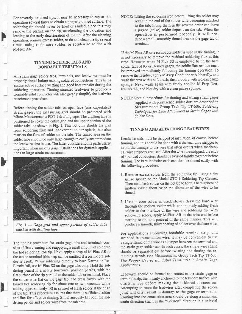
i
For severely oxidized tips, it may be necessary to repeat thisoperation several times to obtain a properly tinned surface. Thesoldering tip should never be fi.led or sanded, since this mayremove the plating on the tip, accelerating the oxidation andleading to the early deterioradon of the tiP. After the cleaningoperation, remoye excess solder, re-tin and clean the tip severaltimes, using rosin-core solder, or solid-wire solder withM-Flux AR.
TINNING SOLDER TABS ANDBOI\.DA3LE TERMINALS
All strain gage solder tabs, terminals, and leadwires must beproperly tinned before making soldered connections. This helPsensure active surface wetting and good heat transfer during thesoldering operation. Tinning stranded leadwircs to Produce aformable solid conductor will also greatly simplify the leadwAeattachment procedure,
Before tinning the solder tabs on open-face (unencapsulated)strain gages, the measuring grid should be Protected withMicro-Measurements PDT-I &afting tape. The clrafting tape ispositioned to cover the entire grid and the upper Portion of thesolder tabs, as shown in Fig. 1. This not only shields the gridfrom soldering flux and inadvertent solder splash, but alsorestricts the flow of solder on the tabs. The tinned arca on thesolder tabs should be only large enough to easily accommodatethe leadwire size in use. The latter consideration is particularlyimportant when making gage installations for dynamic applica'tions or large-strain measurement.
The tinning procedure for strain gage tabs and terminals con-sists of first cleaning and reapplying a small amount ofsolder tothe hot soldering imn tip. Next, apply a droP of M-Flux AR tothe tab or terminal (this step can be omitted if a rosin-core sol-der is used). When soldering direcdy to bare Karma or Iso-Elastic foil, use M-Flux SS on the gage tabs only. Hold the sol-dering pencil in a nearly horizontal position (<30'), with theflat surface ofthe tip parallel to the solder tab or terminal. Placethe solder wirc flat orl the gage tab, and press firmly with thetinned hot soldering tip for about one to two seconds, whileadding approximately \18 in (3 nm) of fresh solder at the edgeof the tip. This procedure assures that there is sufficient solderand flux for effective tinning. Simultaneously lift both the sol-dering pencil and solder wire from the tab area.
NOTE: Lifting the soldering iron before lifting the solder mayrcsult in the end of the solder wire becoming attachedto the tab; lifting them in the reverse order can leavea jagged (spike) solder dei:osit on the tab. When theoperation is performed ProPerly, it will Pro-duce a small, smoothly tinned atea on the gage tab orterminal.
If the M-Flux AR or a rosin-core solder is used in the tinning, itis not necessary to remove the residual soldering flux at thistime. However, when M-Flux SS is employed to tin the baresolder tabs of K- or D-alloy gages, the acidic flux residue mustb€ rcmoved immediately following the tinning operation. Toremove the residue, apply M-Prep Conditioner A liberally, andwash the area with a soft brush; then blot dry with a clean gauzesponge. Next, wash again with fteely applied M-Prep Neu-aalizer 5A, and blot dry with a clean gauze sPotrge.
NOTE: Special procedures for tinning and wiring strain gagessupplied with preattached solder dots are described inMeasurements Group Tech Tip TT'606, SolderingTechnQues for Lead Attochment to Strain Gages withSolder Dots.
TINNING AND ATTACHING LEADWIRES
Leadwire ends must be stripped of insulation, of course, beforetinning, and this should be done with a thermal wirc stripper toavoid the damage to the wire that often occurs when mechani-cal wire strippers are used. After the wires are stripped, the endsof stranded conductors should be twisted tightly together beforctinning. The bare leadwire ends can then be tinned easily withthe foUowing procedure:
1. Remove excess solder ftom the soldering tip, using a drygauze sponge or the Model STC-I Soldering Tip Cleaner.Then melt ftesh solder on the hot tip to form a hemisphere ofmolten solder about twice the diameter of the wire to betinned.
2. If rosin-core solder is used, slowly draw the bare wircthough the molten solder while continuously adding freshsolder to the interface of the wire and soldering tiP. Withsolid-wire solder, apply M-Flux AR to the wire end beforestaning to tin, and Proceed in the same manner. This willproduce a smooth, shiny coating of solder over the barc wire.
For applications ernploying boadable terrninal strips andstranded instrumentation wire, it may be convenieot to usea single strand of the wire as ajumperbetween the terminal andthe strain gage solder tab. In such cases, the single wire strandshould be separaled out before twisting and tinning the re-maining strands (see Measurements Group Tech Tip TT-603,The P.roper Use of Bontlable Terminals in Stain GageApplications.
Leadwires should be formed and routed to the strain gage orterminal strip, then firmly anchored to the test-part surface withdrafting tape before making the soldered connection.Attempting to roue the leadwires after completing the solderjoint will often result in damage to the gage or terminals.Routing into the connection area should be along a minimumstain directior (such as the "Poisson" direction in a uniaxial
Fig, 1 - Gage griil and upper portion of solder tabsmaskeil with drafthrg npe.
- j -
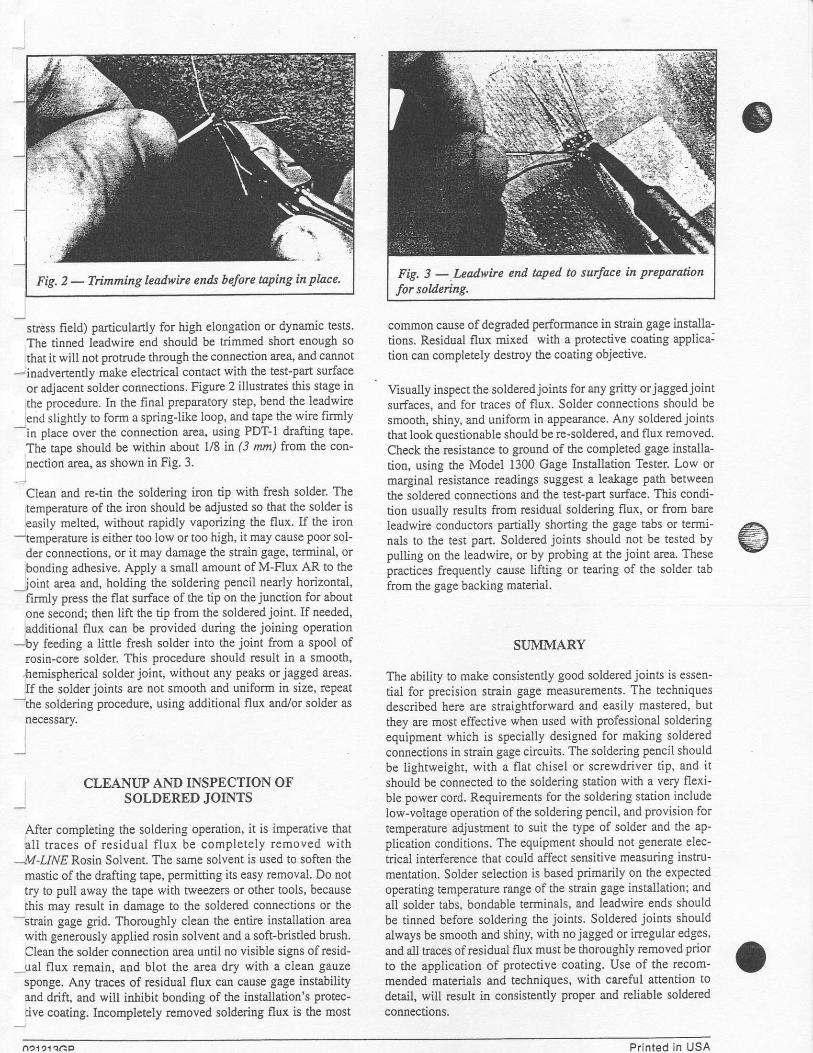
Fig. 3 -.I*adwire end taPed to surface in preparation
for sodering.
stress field) paniculartly for high elongation or dynamic tests'The tinned leadwire end should be fimmed short enough so
that it will not protrude tbrcugh the connection area, and cannot-inadvertently make electrical contact with the test-pan surface
or adjacent solder connections. Figurc 2 illustrates this stage in
the procedure. In the final prepamtory step, bend the leadwteend slightly to form a sprirg-like loop, and tape the wire firmly
-in place over the connection area, using PDT-1 drafting taPe.
The tape should be within abour ll8 it (i mm) from the con-
nection arsa, as shown in Fig. 3.
Clean and re-tir the soldering iron tip with fresh solder. Thetemperaturc of the iron should be adjusted so that the solder iseasily melted, without rapidly vaporizing the flux. If the iron
-temperature is either too low or too high, it may cause poor sol-der connections, or it may damage the stain gage, terminal, orbonding adhesive. Apply a small amount of M-Flux AR to the
joint area and, holding the soldering pencil nearly horizontal,firrnly press the flat surface of the tip on the junctiol for aboutone second; then lift the tip from the soldered joint. If needed,additional flux can be provided during the joiring operation
-by feeding a little fresh solder into the joint from a spool ofrosin-core solder This procedure should result in a smooth,.hemispherical solder joint, without any Peaks or jagged areas.If the solder joints are not smooth and uniform in size, repeat
-the soldering procedure, using additional flux and./or solder as
necessary.
CLEANUP AND INSPECTION OFSOLDERED JOINTS
After completing the soldering operation, it is imPerative thatall traces of residual f lux be completely removed with
--,'t4-t1ME Rosin Solvent. The same solvent is used to soften themastic of the drafting tape, permitting its easy removal. Do rottry to pull away the tape with tweezers or other tools, becausethis may result in damage to the soldered connections or the
-strain gage grid. Thoroughly clean the entire installation areawith generously applied rosin solvent and a soft-bristled brush.Clean the solder connection area until no visible signs of resid-
-ual flux remain, and blot the area dry with a clean gauzesponge. Any traces of residual flux can cause gage instabilityard drift, and will inhibit bonding of the installation's protec-tive coating. Incompletely removed soldering flux is the most
common cause of degraded performance in strain gage installa-tions. Residual flux mixed with a protective coating applica:tion can completely destroy the coating objective.
Visually inspect the solderedjoints for any gritty orjaggedjointsurfaces. and for traces of flux. Solder connections should besmooth, shiny, and uniform in appearance. Any solderedjointsthat look questionable should be re-soldered, and flux removed.Check the resistance to ground of the comPleted gage installa-tion, using the Model 1300 Gage Installation Tester. Low ormarginal resistance readings suggest a leakage Path betweenthe soldered connections and the test-part surface. This condition usually results from residual soldering flux, or from bareleadwte cooducto$ partially shortilg the gage tabs or terld-nals to the test part. Soldered joints should not be tested bypulling on the leadwire, or by probing at the joint area. Thesepractices frequently cause lifting or tearing of the solder tabfrom the gage backing material.
SUMMARY
The ability to make consistently good soldered joints is essen-tial for prccision strain gage measurements. The techniquesdescribed here are straightforward and easily mastered, butthey are most effective when used with professional solderingequipment which is specially designed for making solderedconnections in stain gage circuits. The soldering pencil shouldbe lightweight, with a flat chisel or screwdriver tiP, and it
should be connected to the soldering station with a very flexi-ble power cord. Rcquirements tbr the soldering station includelow-voltage operation of the soldering Pencil, and provision for
temperature adjustment to suit the tyPe of solder and the ap-plication conditions. The equipment should not generate elec-
trical interference that could affect sensitive measuring instru-mentation. Solder selection is based Primarily on the exPectedoperating temperature range of the strain gage installation: and
all solder tabs. bondable terminals, and leadwire ends should
be tinned before soldedtrg the joints. Soldered joints shouldalways be smooth and shiny, with nojagged or irregular edges'and all traces ofresidual flux must be thoroughly removed prior
to the application of protective coating. Use of the recom-mended materials and techniques, with careful attention to
detail, will result in consistently proper and reliable solderedconnections.
Printed in USA

Reference 6

TECH TIPTT-603
BondableTerminals
3.'The polyimide-type terminals (prefix CPF) have thebighest conformability and higbest temperature capabil-ity, and are best for general u.se. Ilowever, the high expan-sion coefficient of unfilled polyimide may cause loss ofboad below -l00oF (-75o C), and the fiberglass-epoxytermiaals (prefix CEG) are thcrefore preferred for cry-ogenic applications.
4. Elecholyticcopperfoilbas aaiaherentlypoorfatiguelife.Whenever possible, orieat the long dimcnsion of thecopper terminal along the sxis of minimum strain. If thestrain level exceeds i500p€, and if the terminal irstal-lation mwt havc a long life under cyclic loading, use the'C'codiguration termiuals cut in hslf as shown in Fig. l.This reduces the bonded length of the terminals, andallows the same solder mass to join both s€ts of wires.Failure of tle copper between solder joints is preventedby this techdque.
5. Use only rosh-type soldering fluxes (such as M-Flux AR)on prioted-circuit terminds, aad. ranove all ffur rcsiduc$ter nldedng. Actd and/ or cbloride type fluxes, particu-lady the paste t]?e, may cause the copper to unbotrd from
Ti! cltit€ qoppcrpad, lcaviog rcst'doDe' of soldcr
Stylc 'C'terEiaalcut io half ledgth-wlle
NOTE: When thc oaiq L.ds"ile is strand.4 it is ofted corv€deutto cut all ltratrds bllt ou. to fit the siz. of the coppc! pad. Thc longskaod can thctr br uscd a! thc juEper wirc. Soldcriag is oadecousidcrably casi€r by this Ecthod.
,-,'- Orcstarnd-r-i-. ---:-- +_ -1
11 1g-a,.rng guatos oelorcsolderilg to tarEioal
Fig. 1 - Eal!-taminal' teclmiqn tor using bondetltermiuls in hish str.sin
o Copyright Measuremenls Group, Inc., 1983All Flighls Roseryed.
The Proper Use of Bondable Terminalsin Strain Gage Applications
It has becoae comnlon practice to employ bondable prhted-circuit terninals between the main leadwire and the rela-tively small ard delicatejumper wires to the strain gage. Theprirnary purpose is to provide an anchor for both sets ofleads, aud to prevent forces transmitted along the mainleadwire system ftom damaging tbe strain gage or degradingits performance. In order to obtain maximum benefit fromthe use of these terminals, they must be installcd with careaad knowledge of their limitations. Otherwise, the termilalcan be a source of performance degradation for tbe cntireinstallation.
Micro-Measurcments orinted-circuit t€rminals areproduced ftom 0.0 014 it (0.03 mm) electrolytic copper foilbonded to a carrier of either polyimide fiIm or fiberglass-rcinforccd cpoxy. Micro-Measurements manufacturts bothtypes ia a wide variety ofcotrfigurations as describcd in M-lVCatalog A-1I0.The following instruotions will assist greatlyirr sheining plspg1 performance from bondable terminals.
l. Select termiral corrfigwstion to match the geometrioalarangemcnt of the gage/ lcadwire system, and select ter-ninal sr?e appropriate to the AWG size of the mainleadwires.
2. Printcd-chcuit terminal strips are usually bonded to thespecinea with th€ same adhesive used to install the gage.After solderi:rg and flux removal, the terminal strip andjurnper wires should be costed vith a protcctive com-pound suitable for the eavironmeat, g€nerally th€ samecompound used over the gage itself.
BONDABLE TERJ\{INAL PATTERNS
TTTTTTTTStyle C' Style D'
l- lStyle T.'
rr tt l lTI TT T I
Style'S'
MEASUREMET{TSGROUP MEASUREMENTS GROUP, INC.
P.O. Eor277nRalelgh, Norlh Caroline 27611, USA
(919) 36s-3800Teler 802-502
FAX (91e) 365.3945

the backing, aad often deate serious electrical leakageproblems, especially at elevated temperature. If tbe lead-wire system is an alloy that must be soldered with acorrosive flux, pre-tin the wire with an active acid fluxsuch as M-Flul SS, renove flux rxidue, and then soldertbe wirc to tle pdnted-circuit ternhd using rosin flux.
Thermal EMf generation and leadwire temperature dif-ferences catr create significant error siglals in strain gagecircuits, particularly when high heating or cooling ratesare iavolved. These problems are miniarized by keepingthermal masses atrd jumper wires as symnetrical as pos-sible. Use neat solderjoitts ot all t€rminals with the sameamount of solder qn each, and kcep alljumper wires thesame lergth from termhal stdp to g€e. Figure 2 showsthe use of a narrow piece of Mylar tape to mask the centerarea of a set of termiaals. This prevents nonuniformsolder spread, and assists in obtairi.Dg thereal symmetry.
Fig, 2 - Na ow piece o! MlIu tqe orfudting trye used to preeent excetsqrcad oJ soklet Remove trye alter sol'dairy, snd deot oll tape ruidae andflut with rosin solvent
7. When terminal strips are uscd with high-elonption straiagages (post-yield measurements), it is Prefenble to locatethe terDi.nal strip at ]f,ut | | 16 n (1 .5 mm) away from theend ofthe gage backingto avoid unbording problems dueto thick areas of adhesive. If the termindl backiag isplaced agaiost the gage backi"g i:r aa M-Boad 200 instal-lation, a "ramp effect' results as shown in Fig. 3, andbondilg failure will occur at the locatiotr shown. The"hall-terminal" techaique @aragraph 4) is usually em-ployed ia high+tougation work if the strai.n level willexceed?lo 3Vo.
8. The Type 'S'terminal, shown in Fig. 4, has a u:riqueconstruction; the hole in the center providcs thermat iso-latioi between the soldering areas. This arrangem€at ispopular where soldering and desoidering of leadwiresmay be €ncountered. Type 'S' terminals ars not recom-mended where high cyclic cudurancc is required.
Fig.l - Use olStyle'S'terninalto make a three-wbe csbleconnection.
9. High g-fields create bigh unbonding forccs betwcen thecopper termiral and backing material. When priated-circuit terBinds must be used i! this type of applicatioD,kcep the solder and lsadn'irs pas5 1s a minimum. When-ever possible, locate the termiral stdp so that the centrif-ugal force is either p arallel to the plane ofthe terminal, orin a perpe,ndicular dirgction qhirch will assist in kgepin_gthe terminal iu place. R.efet lo Measurements Grot4t TechTip TT-601 relaling to tecbniques for bonding leadwiresto surfaces experiensing high centrifugal forces.
10.The figures ia this Tech Tip show various methods ofterminal use in gage circuits. Note that in every case, a"stress relief loope is used in the jumper wires betweenterrni-nal strip and gage to mini i"e forces appted to thegage tabs, and to prevent wire failue at the solderjoints.
Please note that redustion of electromagaetic noisepickup requires special leadwire considerations, aadstress reliefloops may be undesirable ia these cases. Mea-surements Group Tech Note TN-501 provides a detaileddiscussion of aoise control ia strain gagc measurements.
Terminal
Bo!dfailurePout Adh.si*
Fig, 3 - Exaggeratedsfule view ol M'Bond200 hstal'lation with tenninal sbip too close to gtga Excesshteadhesive baikls ap at bottom ol ga$' and lotms a
Jaihre point tader high tuatn condit'ans
Addltional Wire Configuretions
various Eethods of Eakilg three-wile cable couDcctioDs.
2 Style 'C'
Terminals3 Stylc 'C'Terminals
NOTE: Thc abovc Eethodr usitg Stylc 'C' tcraioals caa becoabiacd with thc 'half-tcleia8l'tcchriquc sboptr itr Fi8. 1.
'Ycrtical' strcss-relicf loop. Ofteu uacdwhea gages have irtegral jumpe! lead5.
Sidc Vicw
Use of SEl. 'L' tcrmhd tobrin! Eain lcad cablc off atright-angler to gag€ axis.
No tc.Dinals arc rcqutcdviih a CEA typc gagc. Two ofthc lcadwirEs8tr t{iltCd tc.g.thcr; thcrall thlcc l€adralc tlioacdald soldelcddiftctly to lhecoppcrcoatcdtabs.
002621GP Printed ln USA

Reference 7

TECH TIPTT-612
0uarter-BridgeGircuit
Fig. I - Basic Wheatstone Bridge CbcuiL
'W}ile a mathematical proof is beyond the scope of this TecbTip, it car be shown t!'at if the arm resistances are chosen suchth;t the bridge is resistively sym.metricat about an imaginarylirc drawn tbrough the b'ridge ouput comers (as is the case withmost commercially available stain gage instumentation and asassuraed in this Tech lip) the differential ouFut voltage (er)
will be ideutically zero regardiess of the value of the excitationsuDDlv voltage. Itr this condition, the bridge is said to be rEsis-dvely bakn;d. If the bridge is not in balance, a differentialvoltage will be preseat at the output comers of tbe bridge, and
the magninrde of this outPut Yohsge will be proportional to theg.mount of uubalaice'
wEASUREMENTS
GROUP
V
The Three-Wire Quarter-Bridge Circuit
INTRODUCTION
Since the invention of the electrical resistance strain gage more
tban a half c€lfi.ry ago, the Wleatstone bddge has become the
sensing circuit of choice in most commercially available strain
sase instrumentation. This PoPuladty is due in large measue to
its-inberent ability to 1) detect the small rcsistance cbanges pro-
duced in the sfiain gage when it follows even minute dimen-sional changes on the surface of a test Part under load, 2) pro-
duce a zerd output voltage when the test Part is at rcst, and
3) orovide for compeasation of temperature-iDduced resistancecianges ir tne saain gage circuit. To varying degees, each of
thesJfactors is essential for accuate stain g€e measurcments'
In the majority of stlain gage applications for tbe determinationof the staie of stress on a test-pafi surfacq indiTidual stain g€e
elements, whether ftoE uniaxial or rosette sEain gage configu-rations, arc connected indePendently to the Wheatstone bridgeir a quarter-bridge arrangemenl As discussed in the foliowingsections, the wiriag scheme chosea to comect the stain gage to
tbe bridge circuit has a sigoificant effect on the accuracy of
measured stmin data'
In particular, use of a two-wire coonectiotr is generally not rec-
ommended because it may introduce a signi.ficant resistanceoffset in the stlai! gag€ circuit; temPeratule changes in the lead-
wire syst€m will introduce errors ilto measured stain clata; and
the leadwire system will reduce tbe sensitivity of the stain.gegectcui| Configuting the stail gage input as a thrce-wirc circuitprovides for intrinsic 'bridge balance" and automatic comPen'iation for the effece of leadwke temperaturc changes on mea-sw€d strai! data, and reduces the loss in sensitivity Prcsent i!'
the two-wire configuration. Consequendy, the tbee-wire con-
nection is the recormended hookup for quarter-bridge saaingage circuits for static stain measuleoent,
TIIE WMATSTOI\IE BRIDGE
The Wheatstone bridge circuit in its simplest form €ig' 1) con-sists of four rcsistive elements, or bridge arms (Rl' R2' R3, R 'connected in a series-parallel araqgement, and an excitationvoltaqe source (F). The electical conaections $'here Pails ofbridg-e arms are joined to the leadwires ftom the excitation volt-
age iource are referred to as hPut comers of tbe bridge' A dif-fe;trtial output voltage (er) is measured at the ts'o remainingbridge corners, referred to as output or signal comers'
MEASUREMENTS GROUP, INC.P,O, Box 27177Raleigh, North Carolina 27611, USA
(sr9) 365-3800FAX (919) 36s-3945
ooopyright Measurem€nb Group, Inc., 1996All Rlghts Beserved.
M

TWO.WIRE CIRCUTT
For aa initially balanced bridge, if one of the bridge arms isreplaced with a strain gage of precisely the same resistancevalue aud coljlected with two leadwires having negligible resis-tance, the bridge remains at balance But in practice the lead-wires will have some measurable resistance (R/ as shown inFig. 2, which may re.sult iu a signiflcant lack of syDmetry in the
bridge. This occurs because both leadwires are in series with the
saain gage between, for examPle, the posilive (+) inPut comerand the negative (-) output comer, adding to the gage armresis-tance. That is, the gage ann resistance becomes Rc + zRr.
Fig. 2 - Two-wire quafter-bridge circuit.
As a measue of the magnitude of this effect, consider a 120-ohm sftain gage installed at a distatrce of 20 ft (6 tn) ftom tlj1eiNtrumetrt, and coqnected to the illstrumeD.t with a Pair ofAWG26 (0.4 mtn dia") copper leadwires. At room temperatue,the total resistance in series with the straia gage is about 1.7ohEs. For atr instrumeDt gage factor setting of 2.0, this pro-duces an initial imbalance in the bddge correspotrditrg toapproximately 7000pe. Further, the leadwires are a pamsiticresistance in the gage arm of tbe bridge and efectively reduceor desensitize the gage factor of the saain gage, resulting in areduced signal output wheu the test part is subjected to testloads. For Eodest values of leadwire resistance, tle percetrtageof loss in signal is approximately equal to the ratio of leadwireresistasce to stain gage resistance. I.tr the examPle given here,tlis results ir about a 1.570 loss i! se$itivity.
The initial imbalance may be offset usitrg a strain indicator tbathas a sufEcient balance rauge, or may be (mathematically) sub-tsacted ftom mea.suled stain readings. However, a more seriousproblem may result if the temperatue of tbe leadwires changesduring the meas[rement process, causing a coEesPondil.gcbarge in resistance of the interconaecting leadwircs CoPPerleadwires change itr resistance approximately 22Vo of. theirroom-teEperature resistance value for a 100"F (55'C) tempera-tue change. For the 120-ohm gage circuit above, this wouldresult in an error equivalent to apFoximately 156/r€ for a 10"F(5.5'CJ tempentue change in the leadwire system.
The erors and problems specifically caused by the two-wirecircuit are due to lhe pair of leadwires in series with the straingage. Al1 three of tbe effects discussed here inffease in sevedtywith increased leadwire resistancei and the two-wirc circuitoffers no intrinsic compemation. It is wortb noting that use of a350-ohm strafu gage circuit will reduce each of these effects,but cannot eliminate completely the associated measurementenors. But a straighforward method exists to reduce the loss i!sensitivity, and essetrtially eliminaie the iDidai imbalaace prob-lem and the 6rror that results ftom tempemture changes in theleadwire system. This method involves simFly adding a thirdleadwte to the shain gage circuit as shown in Fig. 3.
TEREE-WIRE CIRCUTT
The preferred circuit for use with a single stais gage in a quar-ter-bridge configuration is the three-wire circuit shown inFig. 3. Itr the two-win circuit, both leadwires are in series withthe strain gage in one arm of the Wheatstone bridge. In thethree-wire circuit, the fust leadwire rcmains in series witb tbestrain gage, but the secoqd leadwire is now in series withduEmy resistor & betweetr the negative inPut and ouq)ut cor-ners of the bridge. Referring to Fig. 3, if thoss two leadwircs arethe sane type and length and exposed to the same temPerature,fl.et rcsislances wiU be equal. The two respective bddgs arEswill therefore be equal in resistance, the bridge is again resis-tively symmetrical about a horizonal line through tbe bridgeoutp[t comem, and the bridge remains balanced regardless ofleadwire temperatule changes, so loog as the two leadwires areat tle same lospectiye temperature. And because only one lead-wire is in series with the strain gage, leadwire desensitization isreduced about 50% compared to the two-wie configuration.The third wire in Fig. 3 is a voltage-sensiag wire only and it isnot in series with any of the bridge arms, therefore it does notaffect bridge balance or temperahfe stability.
E 2 , t - +a+ e6 .
Fig. i - Three-wite quarter-bridge circuit.
While the tbree-wire circuit offe$ seveEl advantages over thetwo-wte circuit, in some special applications involving, forexample, slip rings or feed-tbrough connectors, not enough con-nections may be available for a continuous three-wire systemfrom the gage site to th€ instruEent tefidnals. In these cases,use of a two-wire lead system between the strain gage and theconnector. and a three-wire circuit between the connector andthe measuring instrumetrt is rccommeuded to minimize the totallengt! of the two-wire system.
The foregoitrg discussion applies primarily to mea$rement ofstatic stains with a measuring instrument that proYides dc-coupling between the bridge circuit and the amplifier input ter-minals. For measurement of purely dlnanic strains when onlythe peak-to-peak amplitude of a time-varyiag strain signal is ofinterest, the two-whe system may sometimes be used effective-ly by selecting a sigual-conditioning amPlifier that provides forac-coupling of the input signal, to "block ' the effects of tem-perature-ilduced changes in leadwke resistance on the strainslgDal.
In sunmary, benefits of the tbree-wire circuit include inainsicbridge balance, automatic compeNation for the effects of lead-wire temperahrre changes on bridge balance, and increasedmeasurement sensitivity compared to the two-wirc corfigura-tion. The tbree-wire hookup is the recommended conEgurationfor quafier-bridge stain gage circuits for static strain measule-ment. The two-wte circuit can sometimes be used effectivelyfor special situations such as dynamic-only measurements withac-coupled insuumentation, or in stati.c stlai! apPlicatiotrswhere the length of the two-wire system can be kept very short.
September, 1996 Printed in USA by GP

Reference 8

Micro-Measurements
Strain Gage Accessories
M-Coat A
Ilescriplio*Air-dryihg solvent-thinned (xylene) polyurethane. Transparent. Moderate hardness;eood flexi:biliw. Can be removed wilth M-LINE Rqsin Sblvenr or toluene. Fi.lmihickness 0.005-0.010 in (0.10-0.25 mm) per coat. General-purpose coating for labuse, and as base coating for field applieations. Must be fully cured before addition ofother coatings. Good moisture resisiance. Not readily attacked by many solvents.Convenient to use.
M-Coat A Kit
Csre ldequirementsDries tack-hee at room temperatue in 20 minutes. Completely dry in 2 hours. Normalcure 24 hours at room temperatwe. Chemical resistance and coating hardness increasefor6 toTdays ,
Operating Ten:perature R.angeShort Term: -100" to +300'F C75' to +150" C)I-ong Term: -100" to +250" F (-75" to +120' C)
Shell Lif'e*I yeat at +75" F (+24" C)
Ordering infbnnation
o M-Coat A Kit (as shown above) 4 brush-cap bottles [1 oz (30 ml) ea]

M-Coat F Application InstructionsINTRODUCTION
The M-Coat F Protective Coating Kit is desigftd to fit a widevaxiefy of both bondable and weldable strain gage aPplicatiotrcquirements. Because M-Coat F is easily applied ard requiresno mixing or curing, it is particularly suited for use whereworking conditions are not ideal. Typical applications includepipelines, tutrne1s, bddges, reinforcement ba$ itr concrete,heavy machinery, ships, aircraft, motor vehicles, and pressue
vessels.
This kit contains all materials necessary for instaltration undergeneral laboratory conditions or in hostil-e field etrvircnments.'Contents
includi sef-adhering Teflon@ film; a soft, Pliablebutyl rubber sealant; neoprene rubber sheets; aluminum foiltape; and M-Coat B (an air-drying dtrile rubb€! coating).These matedals can be aPPlied to vertical aad inverted sur-faces without flowirg.
Application of M-Coat F consists of pressing a small piece ofTeflon filco onto tl€ exposed gage foil and lead connections.This is followed by a layer of M-Coat FB butyl rubber toimmediately seal agaiast moistue. For mechanical Protection,a layer of M-Coat FN neopretre rubber is pressed orlto thelayer of EB sealant. In applications exposed to solYents, petro-leum products. or flowing air or water. FA aluminum tape isinstalled over the etrtire installatioa and sealed with M-Coat B.This forms a smooth contour and provides additional protec-tion against moisture and solveots.
The qormal operating temperahue range of M-Coat F is -20"
to +175"F (-i0' to +80'Cr. Operation in an extended mnge of-70' to +250"F (-55" to +120'C) w\llnot damage the coating,but may result in softening or reduction in bond stength. Allkit components have flash points above +llQ'F (+45"C).
Shelf life is one year.
HANDLING PRECAUTIONS
All components of the M-Coat F Kit arc safe to use whenreasouable care is observed; however, the user is cautionedto: (I) Avoid d,irect contect with M-Coat B: (2) Avoidprolonged or repeated breathing of its vapors; (3) UseM-Coat B only in well-ventilated, areas. IJ skiD contactwith M-Coat B does occur, thoroughly flush the con-taminated area with warm water. Obtain medical attentionin cases of ingestion or extleme exposure. For additionalheaith and safety information, consult the materiai safetydata sheet.
@Rcgist€led Tradema* of DuPolL
Micro-Measurements DivisionMEASUREMENTS GROUP, INC.P.Q. Box27T/7. Aaleigh, NC 27611, USA
INSTALLATION PROCEDTJRES
L Leailwire Preparation and Priming
Step 1Using brush provided, prime viayl-insulated leadwires with alayer of M-Coat B and allow to air dry. It may be desimble tothin the M-Coat B by mixing it 50:50 with methyl ethyl ketone(MEK). Etch uRtreated Teflon-insulated leadwircs with aTeflotr etchant such as Micro-Measurements TEC-I Tena-Etch compound. Separate the individual conductors of flatmulti-conductor cables prior to priming or etching.
Step 2Strip aod tin each teadwire. Strippiog and tindng after primingor etching prevents the pdmer/etchatrt from touching bareconductors.
Step 3Attach the leadwires and remove all soldering fluxes ac-cording to recommended procedures for the materials used.(Refer to M-LINE Accessories Catalog A- 110.)
NOTE: When splicing lengths of leadwire, protect and water-proof the splice joiots with a heat-shrinkable sealant (M-MrrsT-1).
IL Application of M-Coat FT T€flon Film,Fts Butyl Rubber, and FN Neoprene Rubber
Step IClear the gage installation area with a suitable degreasingagent to ensure a tenacious bond of the coating. Cleaned areashould be slightly larger tban the space to be coYered wifhM-Coat F. If the surface of the specimen is betow +40'F(+5"CJ, warm with a heat gun, heat lamp, etc., for best rcsults.
Step 2Cut a piece of M-Coat FI Teflon fiLn large enough to coverall exposed electrical surfaces on the gage installatiou. Onopen-faced gages this would irclude all foil areas and soldercontrections. On encapsulated gages, only the solderconnectioas need be covered. The fil.Eo should extend 1/16 in(1.5 nm) beyordbarc foil and electrical comections. Press inplace.
Step 3Cut a patch of M-Coat FB butyl rubber sealant large enough toeKterld ll2 in (13 no ) beyond the three open sides of the gage(or Teflon filn), and at least 1-114 ia (30 mm) beyord tlle end
Telephone (919) 365-3800FAX (919) 365-394s
@Copyright Measurements Group, tnc., 1978All Rights Fleserved.
Printed in USA by PPAugust, 1994

of the gage or termiml strip ftom which the leadwtes exil Ifthe gage-bonding adhesive extends beyond this ares, increasethe size of the patch accordingly. This is particularly imPortantwith M-Bond 200 cyaroacrylate adhesive.
Step 4Remove the protective paper from one side of the M-Coat FBpatch. As shown in Fig. 1, press this exposed area to thesurface of the insta.llation, beginning at the end opPosite theleadwires and stopping 114 it (6 mtn) past the solder con-nections. Leave I ia (25 mn) ot he sealant exPosed as shown.
Fig. I
Step 5Usiag tweezers, raise each lead and tack to the coating, Use adental probe to form tbe sealaut arould each lead, beingcarcful oot to puncture tie sealant (Fig. 2a). Firmly press theremainder of the patch onto the specimen surface (Fig. 2b).
PROTECTIVE PAPER
SEALANT OVEREACH LEADWRE
Step 6For mechanical protection, cut a patch of M-Coat FN neo-prene rubber to the same size as the butyl rubber sealatrt, Re-move the protective paper ftom the butyl rubber, and press theneoprene in place (Fig. 3).
NEOPRENE FUEBERFig. 3
Step 7M-Coat FA aluminum tape can serve as a convenietrt leadwircrestraint. For maximum stength, fold as shown in Fig. 4.
Itr. M.Coat F Installation with Aluminum Tape
In applications exposed to solvetrts, petroleum products,flowitrg water or air, installatiotr of alumi!.um tape atrd sealingwith M-Coat B offers increased protection. The aluminum taPecontou$ the iustallation and leadwte routing; application ofM-Coat B ssals the edges.
Step 1 through 5Follow procedules in Steps 1 though 5 in Section II.
Step 6For mechanical protectiotr, cut a patch of M-Coat FN neo-preue rubber approximately ll4 in (6 mrn) smaller (on allsides) than the butyl rubber. This technique minirnizes theoiherwise steep edge over which the alumiaum tape isinstalled.
Step 7Cut aluminum tape to a length at least 1 in (25 mtn) lotgerthan the installatio!, and long enough to cover the desiredlength of leadwire. Press the foil flrmly into place arcuud theiNtallatior aod leadwires. Smooth the tape edges with a bluotinstrument.
Step IApply two coats of M-Coat B to the taPe edges, payingparticular attention to the lead exit area. Allow the frst coat todry to the touch before applyi-ng the second. Figure 5 il.1us-trates a completed installatioo.
NOTE: wlen a 1ow-profile installation is desired, the FNneoprene sheet can be eliminated ftom the assembly. How-ever, caution must be exercised with this method since itprovides less mechaoical protection.
Various installation techniques are described on pro-fessionally prepared videotapes available from theMeasuremeuts Group. Request Bulletin 318 for d€tails'
KIT CONTEI{TSM-Coat FT - Sef-Adhering Teflou Film
I pc. 4 in (100 mn) squ.are x 0.003 iu (408 rnrn) thick
M-Coat EB - Butyl Rubber Sealant12 pcs- 3.7 5 n (95 mn) sqtaft, 0.125 in, ( 3.2 n)frrick
M-Coat FN - NeoFen€ Rubber Sh€ets12 pcs.3.75 in (95 run) sqnede,o.lE in (3.2 mm) ttuck
M-Coat FA - AIuEiEum Foil Tape0.003 n (0.08 mtd tickx2'tt (50 twn)' ide x 20 ft (6 n) loag
M-Coat B - Ai!-Dryitrg Nitsile Rubber Coathgtwo 0,5-oz (15-nIJ brush-cap bottleJ
BI]LK REORDER QUANTITMSM-Coat FB-z - Butyl Rubber sealaat (25 pcs.)
M-Coat FN-2 - NeoFene Rubber Sheets (25 pcs.)
M-Coat FA-2 - Aluminum Foil Tape - zGft f6-tr) ro[
M-Coat B - Air-Drying Nitrile Rubber Coatingfour 1-oz (30-nl) btltsh-cap botdes

I
I
I
a
I
..,}
I
I
Reference 9
i
I
J
I
I
I
l
I
I
I
I
I
-.']
I
J

D TECH TIPTT-611
ConcreteStructures
degreaser such as CSM-1A may be needed if oils and greasesare present. Remove surface irregularities with the wire brush, adisc sander, or grit blaster Blow or brush all loose dust ftom thesurface.
. Conditioning
Ger:ercusly apply M-Prep CoD.ditioner A, a nildly acidic solu-tion, to the surface in and arouad the gaging area. Scrub with astiff-bristled brush. Blot contaminated Conditioqer A withgaue sponges. Rinse the area thoroughly witb clean water.Reduce the surface acidity by scrubbing with M-Prep Neutral-izer 5,A'. Blot with gauze sponges and rinse with water. Dry thesurface thoroughly. Warming the surface gendy with a propanetorch or heat Cun will hasten evaporatioD.
Strain Gage Installations for Concrete Structures
INTRODUCTION
The installatiotr of straitr gages for concrete stnrctures pre-sents several unique challenges to the installer, whethermeaswements ate made on tle concrete surface or withir thecondete, or on reinforcemetrt baxs within the saucture. Forexample, special preparation is required to ensure thatstrains on the irregular surface of the concrete arc ful1y tratrs-mitted to the strain.gage; and when gages are bonded to reia-forcement bars, provisions axe necessary to protect theinstallation ftom mechanical damage during fabrication andfrom the hostile environmeDt of the concrete itself. ThisTech.Tip oErlines recommendalions for gage, leadwire andprotective coating selections and installations under theseconditions. The surface preparation materials and imtalla-tion accessories referenced throughout are described indetail in Micro-Measurements Catalog L-110, M-LINEStrain Gage Accesories.
INSTALLING STRAIN GAGES ON CONCRETTAND OTIIER IRREGIJLAR SURFACES
SEain gages can be satisfaclorily bonded to almost aDy solidmatedal - itrcluding concrete - if tbe surface is properl.y pre-parcd. For smooth surfaces ou uotrporous materials, only thebasic oleratiols of solvent degreasing, abrading, application oflayout lines, conditioning and leutralizing are required. Forcon$ete and other materials with ah uneven, rough and poroussurface, an exaa operatioa must be added to fill the voicls andseal the surface with a suitable precoating before the gage is
De$easing
Use a stiff-bristled brush atrd a mild detergent (Fig. 1) to removeaay loose soil or platrt growth. Rinse with clean water. A
MEASUREMENTS GROUE INC.P.O. Box 27777Raleigh, North Carolina 27611, USA
(919) 365€800FAX (919) 36s-3945
http ://unw.measurementsgroup.com
@Copyright Measurements Group, lnc., 1995All Rights Rgsgrved.
Fig. 1 - Condilioning the surfoce for gage installation
n wEASUREMENIS
,GROUP
VM
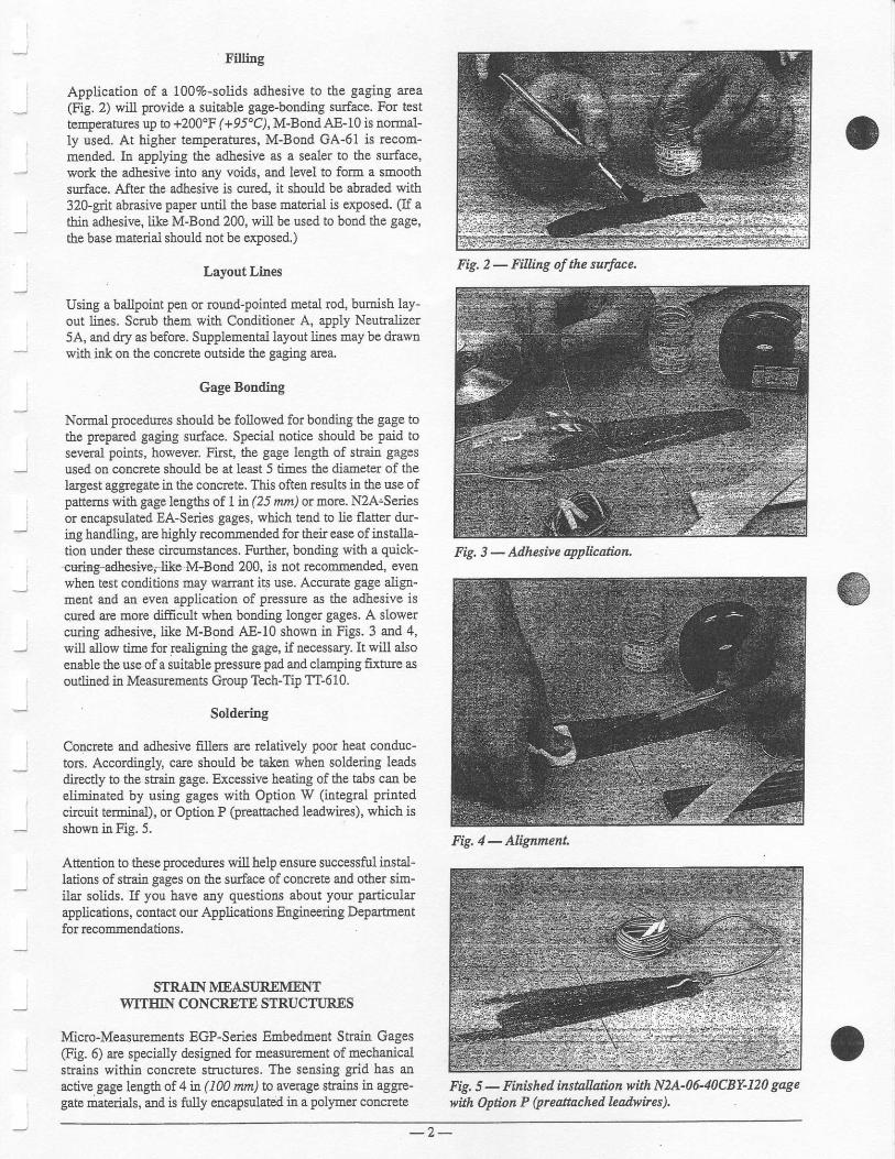
Fining
Application of a ioo%-solids adhesive to the gagiEg area
@g. 2) will provide a suitable gage-bondiag surface. For testtemperatures up to +200"F (+95"C), M-Bond AE-10 is normal-ly used. At higher temperatures, M-Bond GA-61 is recom-mended. In applying the adhesive as a soaler to the surface,work the adhesive into any voicls, and level to form a smoothsurface. After the adhesive is cBTe4 it should be abraded with320-grit abrasive paper untd the base naterial is exposed. (If athin adhssivs, like l\4-Bond 200, will be used to bond the gage,the base material should not be exposed")
Lsyout Lines
Using a ballpoiut peu or rourd-pointed metal rod, bumish lay-out lires. Scrub them with Conditioner A, apply Neutralizer5A, and dry as before. Supplemental layout lines may be drawuwi& ink otr the cotrfiete outside the gaging arca.
Gage Bontling
Normal plocedurcs should be followed for bonding the gage tothe prepared gaging surface. Special notice should be paid toseveral points, however Fhst, the gage length of shai! gagesused on conqete should be at treast 5 times the diameter of thelagest aggregate in the concete. This often results in the use ofpanems with gage len gfts of L Ia (25 nltn) or more. NzA.Seriesor encapsulated EA-Series gages, which tend to lie flatter dur-ing haadling, are higbly recommended for their ease of installa-tion under these circunstances. Further, bonding with a quick-curiagadhesivel like M-Bond 200, is not rccommended, evenwhen test conditions may warrant its use. Accurate gage align-meut ard an even appl.ication of pressure as the adhesive iscured are more dificult wheu booding longer gages. A slowercuring adhesive, like M-Bond AE-10 shown in Figs. 3 and 4,will allow time for realigni:rg the gage, if necessary. It will alsoenable the use of a suitable pressure pad and clamping fixture asoudined in Measuements Group Tech-Tip TT-610.
Soldering
Coacrete and adhesive fillers are relatively poor heat conduc-tors. Accordilgly, care should be taken when soldering leadsdtectly to the stain gage. Excessive heating of the tabs can beelininated by using gages with Option W (itrte$al printedcircuil terminal), or Option P (preattached leadwires), which isshown in Fig. 5.
Attention to these procedures will help ensure successfirl instal-lations of strain gages on the surface of concrete atrd other sim-ilar solids, If you have any questions about your particularapplications, contact our Apptcations Engineering Depaftnetrtfor recommendations.
STRAIN MEASI]RAVIENTWITEIN CONCREIE STRUCTIJRXS
Micro-Measuements EGP-Series Embedment Strain Gages(Fig. 6) are specially designed for measurement of mechanicalstrains within concrete structures. lhe seming grid has anactire gage length of 4 it (100 run) to ayel3:ge stains in ag$e-gate materials, and is firlly encapsulatdd in a polymer concrete
Fig, 5 - Finisheil installdion with MA-0640C8Y-120 gagewilh Option P (preanached lzadwires).
Fig. 2 - Fihing of the surface.
Fig. 3 - Adhesive qplication
Fig, 4 - Nignment.
- 2 -

D
material to closely match the mechanical propertiss of typicalsEuchual concrete, guard against mechanical damage, and toprotect against moisture aod corlosiye attack. EGP-SeriesGages incorporate a. l0-ft (j-m), jacketed, three-conductorcable for ease of use in field installatioDs, and are compatiblewith conventional stain measEement instrumentatioE.
Gage Installation
No preparation of the gage itself is required; howeve! as with-bo.sdgd,.pt ge-!d,p-d-s$arn. gages, EGP-Series Gages must beaccuately aligned along the intended shain measulemetrt direc-tior during the imtallation process. Care should be taken tosecule the gage in the desired location and orientatioD, and to tietie leadwirc cable to any available support, befole the concreteis poured. While the EEb€dment Gage must be completelyencapsulated in concrete to ensue complete stlaia transfer fromthe strucfirle, normal pouring techniques are usually all that arerequAed.
Cable Splices
EGP-Series Gages are provided with a 10-ft (3-n) cable toallow for making cable splices outside ihe concrete struch.re.When splices are requircd, all coa.nections should be solderedand thetr protected ftom moisture add other contamination witha suitable cable splice sealant.
STRAIN GAGE INSTALLAIIONON CONCRETE REIMORCEMENT
Strain gage i.ostallation on reinforcing rofu follows the samegeneral procedure recommended for most steel specimens,These rods are, however, subjected to mecbanical abrasion anda moist, corosive enrrircD-Eent Accordingly, the following spe-cial anerrion is required:
Surface Preparation
1. Degxease with a degreaser (CSM-1A) over at least a 6-in( 150-mm)lengfh of fte bar at the proposed gage locatiou.
2. Descale and smooth the rebar arouad its circumference witha grhder wheel. (Aluminum oxide or silicon carbide abra-
siye of apprcxi.mately 50 mesh is preferred .) A3-in (75-mn)
length generally provides a suffi.ciendy large descaled arcafor gage and protective coating irstallatiors. Surface finishafter this operatioq should be about 180 microinches(5 W) tms.
3. Wet abrade with Conditioner A aud 22Ggrit silicon carbidewet-or-dry paper (SCP-1). Use sufEcient Conditioaer A toprevetrt material from drying on the rebar surface whileabrading.
4. Wipe dry with a clean gauze sPonge (GSP-l), then rePeatStep 3 (wth 320-gnt paPer) aud dry again.
5. Surface finish should be 63 to 125 micrciach ( 1.6 to 3.2 W)rms at the completion of the second wet-abrading operation.
6. Lay out the gage locations.
?. Scmb the iustallatioa area with Conditioner A aqd a cottonapplicator (CSP-1). Wipe dry with gauze sponges.
8. Scrub the area thorougbly with Neutrdlzer 5,A aod a cottouapplicator and wipe dry with a gauze sponge as previouslyooted. This step must be accomplished thoroughly to neu-tralize all toaces of Conditioner A used in Steps 3 through 7.
9. Mask atr ar€a with PCI-2A cellophane (or MJG-2 Mylar@)tape at the gage location to minimize flow-out of adhesivefor subsequent prctective coating alplication.
Adhesive Selection
M-Bond An-i0 adhesive is a good selection wh€o a room-temperature cure of a field application is required. Thisadhesive will cure iu 6 hours at +75'F (+24"C). Other adhosivesthat may be used, depending upotr the test envtonmeot, areM-Bond AE-15, M-Bood 600/610, or GA-61 adhesive. Appli-cation of the arlhesive should follow the specific insauctions&LvuP@JruE n.
Gage Selection
CEA-Series gages are the most popular choice when tbe crosssection of ttre bar is Ll9ln (3tnm) or larger in diametel merevery stable irstallations arc requfted (e.9., for tests i.u excess ofone year) ou 1/4 in (6 mm) or larger diameter rebar rod,WK-Series gages are recommended. When conditions are notfavorable for bonding gages, CEA- and LWK-Series WeldableGages (Fig. 7) may be used.
t1
Fig. 6 - EGP -Seies Embedment Gage.
Fig. 7 - CW-Series Weldable Gage.
- 3 -

Leadwire CoDsiderations
When utilizing one active stain gage (quarter-blidge cotrfigu-ration), it is good practice to use a three-leadwte system.Micro-Measuremetrts EA- and CEA-Series straia gages can besupplied with a preattached three-leadwire cable (Options Pand PS, respectively) to elimimte the need for attaching lead-wires at thejob site, and to reduce installation time.
Altematelt leadq.ires may be soldered to the shair gage tabsafter gage bonding. If a parailel or rwisted cable is used, sepa-rate the individual (leadwire) conductors for a distance of about1 n (25 mm) fuom the cabte end and, if Teflon@-insulated cableis used, elch the insulatior with Tetla-Etch compound; if vinyl-itrsulated cable is used, prime the insulatiotr with thinnedM-Coat B. These materials should not be allowed to flow ontothe bar strands of the conducto$.
After allowing the M-Coat B to air dry for at least two hours atroom tempemtue labout +75' (+24"r], thermally srip the lead-wire ends and tin and solder the wires to the stain gage tabs,For most lebar installations, 361A-20R solder will give excel-lent results. Carefully, remove all losin flux ftom the soldercdconnections usiag rosia solvent (RSK-l) before applying the*^r--.i'- -^ari-'
Enviroamental Protection
Apply M-Coat J to tbe gage installatioo carefully fol.lowing theprocedures oudined in Mcro-Measurements Itrstruction Bul-letin B-14?. The coating should be built up to provide approxi-mately 1/4 in (6 rurn) thickness completely surounding therebar @ig. 8) at the gage location, and should be carried backfar enough to cover the leadwLe area previously primed with
Fig. 8 - Cut-away view of installatinn.
M-Coat B. Allow this coating to cule 24 hours at +75oF(+24'C), or +hows at +L25'F (+50'C).
As a flnal step, the instrumeutation leads extending from thegage, out tbrough the concrete, should be placed in conduit toprevent mechaqical damage to the leadwire system. Of couse,the complete installations should be thorougbly checked with aModel 1300 Gage hstallation Tester befole and after the con-crete is poued. A Foper$ installed aad protected shain gage iscapable of maay years of service on embedded reidorcing bars,providhg data about load effects throughout the ffe of a con-crete structure - ftom initial construction forces to unexDectedsevere loading cooditiors.
February 1998 Printed in USA by GP

The EGP-Series Embedment Strain Gage is specially designed for measuring mechani-cal strains inside concrete Structures. The sensing grid, constructed of a nickel-chromiumalloy (similar to Karma), has an active gage length ot 4 in (100 mm) lo( averaging strains inaggregate materials. A rugged s-in (130-mm) outer body of proprietary polymer concreteresists mechanical damage during pouring, minimizes reinforcement of the structure, andprovides protection from moisture and corrosive attack. The grid, cast within the polymerconcrete to ensure maximum strain sensitivily, is self-temperature-compensated to minimizethermal output when installed in concrete structures. Each gage incorporates a heavy-duty1}-ft (3-m) cable with 22-AWG (0.643-mm dla.) leadwires; a three-wire construction to thesensing grid helps minimize temperature effects in the instrumentation leads. Special lengthsof preaftached cable will be quoted upon request. Micro-Measurem ents M'LINE accessorycable 322-DJV is available for adding cable length in the field.
Rugged and reliable, Micro-Measurements EGP-Series Strain Gages are available in both120-ohm (EGP-5-120) and 350-ohm (EGP-5-350) resistances.
Specifications
eonstr{.rcti@n. Strain sensing grid cast in asturdy, water-resistant material.
Sensifig Gricl. NickeFchromium alloy onpolyimide backing. Active gage length of 4 in(100 mm), nominal. Grid resistance of 120 or350 ohms, r0.8%.
Outer Eody. Proprietary polymer concrete.5x0.7x0.4in (130x 17x 10 mm) nominal
Oable. Three 1o-ft f3-m, leads of 22-AWG(0.643-mm dia.) stranded tinned copper in0.015-in (0,4-mm) thick PVC insulation.Nominal cable diameter of 0.2 in (5 mml(Other lengths quoted upon request.)
Ternperature Range. The normal usage rangeis +25" to +125'F (--5" to +50'C). Exendedrange is -25o to +150"F (-30'to +60"CIMaximum exposure (temperature) should notexceed +220"F (+1 05'CI
Packaging. One strain gage per pacl(age.
lnc.27777
1, USA
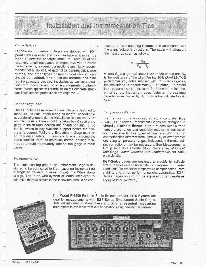
Cable Splices \
EGP-Series Embedment Gages are shipped with 1o-ft(3-m) cables in order that most leadwire splices can bemade outside the concrete structure. Because of therelalively small resistance changes involved in slrainmeasurements, soldered connections are highly recom-mended for all splices. Alligator clips, banana plugs, wirecrimps, and other types of mechanical connectionsshould be avoided. The eiectrical connections alsorequire adequate electrical insulation, as well as protec-tion trom moisture and other environmental contami-nants. When splices will reside inside the concrete struc-ture itself, special precautions are required. -' '
Sensor Alignmeit
The EGP-Series Embedment Slrain Gage is designed tomeasure the axial strain along its length. Accordingly,accurate alignmenl during installation is necessary.foroplimum results. Care should be taken to (a) secure thegage in the desired location and orientation and, {b) tiethe leadwires to any available support betore the con-creie is poured. While the Embedrnent Gage must beentirely encapsulated in concrete to ensure completestrain transJer from the structure, normal pouring tech-niques should adequately embed the gage in mostcases.
lnstrumentation
The strain-sensing grid in the Embedment Gage is de-signed to be connected to the measuring instrument asa single active arm (quarter bridge) in a Wheatstonebridge. The three-wire system of leads, employed tominimize thermal etfects in the leadwires. should be con-
nected to the measuring instrument in accordance withthe manufacturer's dlrections. The cable will attenuatethe measured strain as follows:
D= RGRG+Rc
where: Fc = gage resistance (120 or 350 ohms) and F,is the resistance of the wire. [For the 1o-ft (3-m)22-AWG
, (0.643-.mn dia.) cable supplied with EGP-Series gages,the resistdnbe is approximately 0.17 ohmsl. To obtainthe measured strain corrected for leadwire resistance,either set the instrument gage faclor at the packagegage faclor multiplied by D, or divide the indicated strainbv D.
Temperature Flange
For thg most commonly used structural concrete (Type. 3500), EGP-Series Embedment Gages are designed to
virtually eliminate lhermal output effects over a widetemperatule range and generally require no correction
,for these effects. For lypes ofrconcrete wlth thermalcharacteristics different trom Type 3500, or over greateroperating temperature ranges, independent thermal out-put corrections may be necessary. See MeasuremenlsGroup Tech Note TN-504, Strain Gage Thermal Outputand Gage Factor Variation with Temperature, lor com-plete details.
EGP-Series gages are designed to provide for reliablestrain measuremeht under demanding environmentalconditions. To preserve temperature compensation, zerostability and other performance characteristics, EGP-Series gages should not be exposed to temperaturesabgv,q'+220'F (+ 1 05'C).
The Model P-3500 Portable Strain lhdicator and/or 2100 System are Iideal for measurements with EGP-Series Embedment Strain Gages.Detailed information about these and other stress/strain measuringinstruments is available from our Applications Engineering Department.
Printed in USA by GP May, 1996

Reference 10
JJ
IJ
_lI
Il

-ir^
T
;
J
i
Noise Control in Strain Gage Measurements
Noise Controlin Measurements
Introiluction
Suain measurements must often be made i[ the gesence ofelectric and/or magnetic fields which can superimpose electri-cal noise on the measuemeut signals. If not controlled, tbenoise can lead to iDaccuate results and incoFect interpretationof the strain signals; 4tr4 in severe case,s, can obscure tle strainsignals altogetber. In order to control the mhe level, and maxi-mize the signal+o-noise ratio, it is necessary fimt to unde$tandthe types and characteristics of electrical noisq as well as thesources of such noise. with &is understanding, it is then Possi-ble to apply the most effectiye noise-reduction measures to anyparticul.ar instumentation problem.
This technical note identifies some of the more corlmonnoise soEces, .and describes the rouies by which the noise ishduced into strain gage circuits. It should be noted that th€teatment here is limited to noise from external eleccical ardmagnetic sources. This note does not cover effects ftom uuclea!or thermal sources, nor does it consider the effects of variablewidng or contact resistance caused by slip rings, connectors,switches, etc. Following the discussion of noise sources, specif-ic rnethods are giveu, varyi:rg with the noise-coupling mecha-nism. for noise avoidance. The information in this technicalnote is equally applicable to botb amlog ad digital systemsemploying dc anplifre$. It also applies to systems using carri-er excitation and carrier amplifiers.
Noise Sources and Pickup Media
Virtually every electrical deyice rthich generates, consumes,or traDsmits power is a potential source for causing noise instaio gage circuits. An4 in geaeral, the higher the voltage orcurreat level, and the closer the sEain gage circuit !o the electri-cal device, the greater will be the induced ooise. Following is alist of common elechical noise sources:
. ac Powernnes
. motors aDd motor stariels
. tsansformers
. relays
. Seneraiors
. rotating and reciprocating machinery
. arc welders
. vibrators
. fluorcscent lamps
. radio kansmitters
. electrical storms
. soldering irors
Electrical noise ftom these sources can be categoriz€d intotwo basic types: elecEostatic and magrctic. The two tyPes ofnoise are fundameutally different, and thus require differentuoise-reduction rneasues. Udorfiroately, most of the commonnoise sources listed above produce combiaatiols of the fwonoise types, which can complicate the noise-reduction problem.
Electrostatic fields are generated by the presence of voltage- with, or without curcnt flow. Altemating electrical fieldsinject noise into strain gage systems through tle phenomenonof capacitfue coupling, by which charges of conespondinglyalternating sign are developed on auy electrical condocto$ sub-jected to the field (Fig. 1). Fluorescent lighting is one of themorc conmon souces of electrostatic troise.
Electrostatlc Field
Stray Capacitanc€
Accumulalsd Charges
Signal wlre
Fig. 1 - Electrostatic noise coupling.
Jr
i*
9;d@Copyright Measurements Group, Inc., 1992All Rlghis Fleserved.

Magnetic fie1ds are ordinarily created either by the flow ofelectric curreqt or by the presence of permaneBt magnetism.MotoE and transformers are examples of the former, ald theearth's nagnetic field is ar. instance of the latter. In order fornoise voltage (enf) to be developed in a conductor, Eagnoticlines of flux must be "cut ' by the conductor Electric generatorsfirnction on this basic principle. In the prcsence of an altemat-ing field, such as that surounding a 50/60-Hz power line, volt-age will be induced into any statioaary conductor as the mag-uetic field expands aad collapses (Fig. 2). Sinilarly, a conduc-tor moving through the earth's magnetic field has a noise volt-8ge generated in it as it cuts the lines of flux, Since most ironsand steels arc feco-magnetic, moving machine members redi-rect existitrg lires of flux, and may cause them to be cut by adja-cent sensitive conductors. As a result, signal conductors in theviciuity of moviog or rotating Eachinery are generally subjectto troise Yoltages ftom this source,
Fig. 2 - Electrornagnetic noise coupling,
Detecting and ltoubleshooting
Lo order to effectively assess the presence and magnitude ofnoise, the stain gage hstrumetrt selected for use should incor-porate a simple, but very sig!.ificaat feature - a switch forremoving the excitation ftom the Wheatstone bridge. With sucha control, the instrument output can be easily checked for noise,independendy of any strai.u signal. This reFesetrts a very pow-erful tool for evaluating the effectiveness of shields and ground,and for experimeltally modifying these methods to m;nimizethe effects ofnoise, All Measurements Group sfiain gage signalconditioners are equipped with this important featue.
The following prccedure can be used to toubleshoot a sys-tem for noise:
1. If not already known, deterrniae the tolerable levels of noisein output uaits (Eillivolts, irches of deflection, etc.) asobserved on a readout such as au oscilloscope or lecorder.
2. Consideration should be givetr fiJst to noise sources affect-ing the strain indicator itself, isolated ftom all ertenal cir-cuits. For tbis purpose, discomect any sttab gage leads, aEdterEfuate the S+/S- amplifier input with about the sameinput jmpedance that the anplifier normally senses (rypical-
ly between 120 and 1000 obms). IJ excessive noise exists;
a) Check for ground loops (more tbaa one connectiotr of thesystem to gIound).
b) Check for line- ("mains]') radiated noise.
c) If feasible, reduce amplifier gaio aud comPensate byincreasing bridge voltage.
3. Havhg eliminated or satisfactorily minimized noise pickupby the instrument, turtr next to the oxtemal circuitry. Withtlle excitation switch set to ofi cotrnect the gage or tansduc-er circuit (including leadwires) to the instrument, andobserve noise. Of course, a.ny additional noise picked up inthis step is attributed to leadwirc aud/or gage pickup. If theoutput changes when the insbument chassis is touched witha finger, this is an indicatioo ofa poor gound and/or radio-f.-^,,---- i-r-.€A.an^A!w!{swuvj ruevr^!rvq!v.
4. Apply a load to the part uDder tost (with excitation still of0.If additional noise is observed, dre noise is due to somethbgassociated with the loading system such as a motor qeating
a magnetic !eld, or the motion of the gage or wiring (gener-atiug emf).
5. If possible, remove the load ftom the test part and applyexcitation voltage to the bridge circuit. After balancing thebridge, any subsequent change io output, if gradual, is zero-drift, not noise. This may be due to gage seu-heatitrg effects(see Measuremetrts Group Tech Note TN-502, Sfiain GageExcitation Levels) - or other time-dependelt resistancechanges.
The following sections of this Tech Note give recommendednoise-reduction procedues for electrostatic noise, atrd for mag-netic noise.
Electrostatic Noise Reduction
The simplest aad most effective barrier agahst electrostaticnoise pickup is a conductive shield, sometimes refened to as aFaraday cage.lt trrctions by capturiag the charges that wouldotherwise reach the signal wiring. Once coUected, these chargesmust be drained otr to a satisfactory grcund (or rcfererce potetr-tial). If not prcvided q/ith a low-resistance drainage path, thecharges can be coupled into the signal conductors through theshield-to-cable capacitance (Fig. 3).
Electrostatic Source
Stray Capacitance
Conductors
GroundShield-lo-Cable Capacitance
Fig,3 - Elecftostitic shielding.
LVr+v2
_-\Series-lnduced Voltage (Yr > Yt
- 2 -
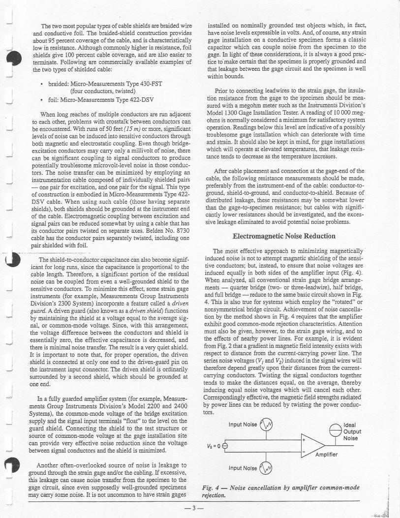
I
Tbe two most popular q4res of cable shields are braided wirea-nd conducdve foil. Tbe bnided-shield construction Providesabout 95 percent coverage of the cable, and is characteristicallylow in resistarce, Although commonly higher in resistance, foilshields give 100 percent cable coverage, atrd arc also easier toterminate. FoUowing are cosr.mercially available examples ofthe fwo types of shielded cable:
. braided: Mi{o-Measurenents Type 430-FST(four conductoE, twisted)
. foil: Micro-Measuremens Type 422-DSV
Whert long reaches of multiple conductors are run adjacentto eacb other, problems with crosstalk between cooductors calbe encouatered. With runs of 50 feet (15 /z) or morc, signiflcatrtlevels of aoise can be iaduced into sensitive conductors tbrcughboth magnetic and electrostatic coupling. Even though bridge-excitation cooductors may carry only a millivolt of loise, therecan be signif,icant coupling to signal cotrducton to producepotentially troublesome rnicrovolt-level noise itr those conduc-tors. The troise transfer can be minimized by employing aninstrumentation cable composed of ildividually shielded pairs- one paft for excitation, and one pair for the signal. This typeof construction is embodied iD Mido-Measuements Type 422-DSV cable. ften using sucll cable (those having separateshields), both shields should be gounded at the instrumetrt eudof the cable. Electomagnetic coupling betweotr excitation andsignal pairs caa be reduced somewhat by usirg a cable drat hasits conductor pairs twisted on separate axes. Belden No. 8?30cable has the conductor pats sepantely twisted, including onepair shielded with foil.
The shield-to-conductor capacitalce can also become signif-icant for long runs, since the capacitance is proportional to thegable length. Therefore, a significant ponion of the residualroise cao be coupled from even a well-grounded shield to thesensitive conductors. To minimize this effect, some strain gagehskuments (for example, Measuremeuts Group InstuumentsDivision's 2300 System) incorporate a featwe called a drivenguard. A, dive\ gu:td (also klown as a d/iven s&ieldl functionsby maintaining the shield at a voltage equal to the avemge sig-nal, or common-mode voltage. Since, with this arrangement,the voltage difference between the conductors and shield isessentially zero, the effeccive capacitance is decreased, andthere is minimal noise transfer The result is a very quiet shield.It is importatlt to note that, for proper operation, the drivenshield is connected at orfy one end to the driven-guard pin onthe instrument bput coonector. The driveu shield is ordinarilysurrounded by a second shield, which shou.ld be grounded atone end.
b. a fully guarded ampli.fier system (for example, Measure-meats Group Instuments Divisiou's Model 2200 and 2400Systems), the common-mode voltage of the bridge excitatiousupply and the siglal input terminals "float" to the level on theguard shield. Connectlng the shield to the test strucfl[e orsource of common-mode voltage at the gage installation sitecan provide very effective troise rEductiotr since the voltagebetween signal conductors and the shield is minimized.
Another often-overlooked source of noise is leakage toground tbrough the stlai! gage and/or the cabling. If excessive,this leakage can cause noise transfer from the specimetr to thegage circuit, since even supposedly well-grounded specimensmay carry som€ noise. It is oot uncommon to have sFaitr gages
i$talled ou nominally grounded test objects which, iD fact,have uoise levels expressible in volts. An4 ofcourse, any stlaingage installatioTl on a conductive specimen forms a classiccapacitor which can couple noise from the specimerl to thegage. In tight of these considerations, it is always a good prac-tice to make certaiu that the specirnen is properly grounded audthat leakage between the gage cilcuit aEd the specimen is wellwithin bounds.
Pdor to connectbg leadwires to the strain gage, the insula-ti6! resistance ftom the gage to the specimen should be mea-sued with a megohm meter such as the Instrumelts Division'sModel 1300 Gage Installation Tester A reading of 10 000 rneg-ohms is normally considered a minimun for satisfactory systemoperation. Readings below this level are indicative of a possiblytroublesome gage installation wbich cao deteriorate with timeand sbain. It sholld also be kept in mind, for gage installationswhich will opemte at elevated temperahues, that leakage resis-tance tends to decrease as the tempenture increases,
After cable placement and connection at the gage-end of thecable, the following resistance measurements should be made,preferably from the iNtrument-etrd of the cable: conductor-to-ground, shield+o-grouad, and coaductor-to-shield. Because ofdisnibuted leakage, these resistances may be somewhat lowertllatr the gage-to-specimen resistance; but cables with signifi-cantly lower resistances should be investigated, and the exces-sive leakage eliminated to avoid potential noise problems.
Electromagnetic Noise Reductibn
The most effective approach to minimizing magneticallyinduced noise is not to attempt magnetic shielding of the sedsitive conductors; but, instead, to ensue that noise voltages areinduc€d equally in both sides of the amplifier input (Fig. 4).Whetr analyzed, all conventional strain gage bridge arrange-meuts - quafier bddge (two- or tbree-leadwire), half bridge,and fir1l bridge - reduce to the same basic circuit shown in Fig.4. This is also true for systems which employ the "rctated" ornonsymmetrical bridge ctcuit. Achievement of noise cancella-tion by the method shown in Fig. 4 requires that the amplifierexhibit good common-node rejection characteristics. Atientionmust also be given, however, to the stafui gage wiring, and tothe effects of nearby power lines. For example, it is evidentftom Fig. 2 that a $adient in magnetic fie1d inteosity exists withrespect to distance ftom the cffrcnt-carryiag power line. Theseries noise voltages (yj atrd y2) induced in the signal wires willtherefore depend greatly upotr their distances from the current-carying conducton. Tkisting the signal conductors togethertends to make the distances equal, on the average, therebyinducing equal noise voltages which will cancel each othe!.Correspondingly effective, the magnetic field strengths radiatedby power Lines can be rcduced by twisting the power conduc-to$.
Input NoisB ldealOutputNoise
V s = 0Amplifier
Input Nols6
Fig. 4 - Noise cancellation by ampffier common-moderejection.
o
oi
I
' '[!'', "L*jg
- 3 -

, at least, the more twists per urdt cocductor le[gth,
3tandard twisted-conductor cables, such as Belden
t. have sufficient twisting for most apPlications. How-
etrvironments with high magnetic field gradielts, such
reduction in mametic noise pickup. However, therehigh-perneabililty alloys (mu-meial@, for instance)
lt!l
lll ctoseltr ,,,TabsarrS'-Smalli), t,"^KnG)
Best
il[IRi1 \(c)
Best
/Rlbbon \
/r/ cable
\
Twlsted Pairs OnSeparate Axesalea betweetr the wires. For the same reasoq flat rib-
is very protre to noise pickup, and is use in magneticsbould be avoided. Wben necessary to use this tyPe of
optimal conductor allocation, as shown in Fig. 6, carthe pickup. In addition, excess lengths of inPutbe elimbated; atrd uoder no circumstances should
be disposed of by winding into a coil as iUus-
in Fig. 7a. If excess cable length cannot be avoided, itbe folded in half and coiled as indicated in Fig. 7b so that Signal
current loop is iltimately accompanied by aloop. The sar::e cabling consideratious apply
the excitation leads and the signal leads.
the case for elechostatic noise, a simple, groundeddoes rot function as a barder to magnetic
Magnetic shields opemte otr a different principle, andto bend or shunt the magretic field around the co[ductorthan eliminate it. Magaetic shields are made from high-
materials such as iron and other ferro-magneticAt the r€latively low 50/60-Hz power line frequencies
etrcounteled in magnetic noise problems, shield thick-(using common iron for example) on the order of 0.1 in
nm) arc r'eed.ed. before significant troise redoction isHeavy-walled iron conduit ca! also be used to pro-
Fig. 6 - Cable comparison.
Signal
Excess Eliminated
(b)Better
have been developed specifically for magnetic shieldingThese are effective in much thinner sbields than with
Wher faced with the apparctrt necessity for magneticattention should always be givetr to reducing the
at its source. As an example, bafffotners can readily beto minimize the leakase flux.
Severe Noise Environments
preceding two sections have treated the standard meth-ofnoise reduction applicable to the majority of instrumen-
I,Ioblems. This section describes techniques which mayuecessary when very high noise levels are anticipated
(a) (b) (c)Poor Better Bert
Fig, 7 - Handling excess cable.
Elechostatic Fields
Generally, when shielding against audio-frequency electro-static noise Oelow 20 kHz), it is not good Facdce to gound theshield at morc thao otre point. The reason for this is that theground points may be at different voltage leyels, causing cur-rcnt to flow throug! the shield. Cunent flow it sttch groundloops cal induce noise in tbe sigral-caftyitrg conductolsthrough tle same phenomenon that occuts in a tlansformer,
However, for lotrg cables in severe noise esvironments, theshi.eld impedance ftom one end to the other can become signif-icart, particulady with high-ftequency noise sources. Whenthis occurs, the noise charges captured by the shield no longerfrnd a low-resistaoce drain to ground, and the result is a noisyshield. Improved shield performance under such circumstancescao often be obtained by gounding the shield at both ends,and/or at intermediate points - Preferably at points near anylocalized sources of electostatic noise. Multiple-point goutrd
fouDd close to motors, genemto$, and transfome$' Medium Areatwisting may be requiled. For panicularly severe appli-conventional twisting may be inadequate, and it may be
to use a special woven cable as described later.
attaching leadwircs to a suain gage for operation in a
field, cotrnections should be made direcdy to tbe sol-
on the gage, rather than through auxiliary terminals.CEA-Series gages, with copper-coated
Ebs, are particularly suited to this fyPe of aPPlication. As
il Fig. 5 , the gage selection and the widng arrangemerts Fig. 5 - Gage selection and wiring technique.
affect the s'ensitiviry to magnetic pickup. It will bethe prefeFed arrangement miniroizes the suscepti-
iltlililv(c)
Poot
) o I t llo | }€Dat bRI XPFI I+D
l L \ \ _Coiled Excess Excess Folded Tightly
ln Half and Coiled
Ludlum Sieel Co.

connectio i nay also be necessary whe[ ndio-ftequency inter-
fereace (RID problems are encountered' At these frequencies
the shield, or segments of the shield between grounded points,
catr display antenna behavior. By expedmentally grounding the
shield al numerous pohts along its leDgtb, the optimum ground-
ing scheme can be determined.
Although the leadwtes are ordinarily the dominant mediumfor noise inductioo in a strain gage ctcuit, noise Pickup can alsooccur in the gage itself. Wlen needed, a simple electrostaticshield can be fabricated by forming an aluminum-foil box overthe gage and the ushielded leadwire termioations. If the gaged
specimen is small and electrically conductive, aluminum tapewith conductive adhesive should be used to conn€ct the cableshield, the gage shield, and the sPecimen together. Cotrductiveepoxy compounds can also be used for this purPose.
On the other hand, when gages are installed on machinery orother larye, conductive test objects, care must be exercised toprevent the occunetrce of gound current loops in the sbield. Insuch cases, the foil should be electrically iosulated ftom tbemachine. But the machine should be grounded with a heavy-gauge copper wile (at least 14 gauge or heavier depending uponapptcation) cotrnected to the single-point ground rear theimtrument. Care must also be taken to make certain that theshield does not form a short ctcuit to the gage wiriDg. If thecable has two shields, then, ideally at least, a double-foil shieldshould be used over the strain gage. The trvo shields should becoD.Eected together only at the instument end of the cable.
A word about ground connections is in orde!' It is importantare characterized by resistanca,
inductance, and shuot capacitance. As a rcsult, atteotion shouldalways be given to tbe quality of the ground connections. To beeffective, a coinection to ground should be made with heavy-gauge copper wire, and should be as short as practicable. If thenearest eartb ground is too lemote, a 6-ft {2-n) copper rod canbe driven into the earth to establish a local ground.
Electromagretic Fielals
As with electostatic noise pickup, the leadwires commodyrepresetrt the pril1cipa] souce of magnetic noise induction instraio gage chcuits. In irtense electromagnetic fie1ds with steepgradients (near motors, generators, and similar equipment),ordinary wire-twisting techdques may prove inadequate. Anend view of a conventionally twisted pair can reveal the reasonfor pickup. As indicated ir Fig. 4, even if the induced qoisewere precisely equal in both wires the amplfier noise ouputwould be zero only if the amplifier had infinite common-modercjectiotr characteristics - an impossibility. In order to mini'mize commoq-mode noise voltages, a special, woven, four-wirccable has been designed which, as seeu ftom the wirc end, elim-inates the spiral inductive loops (Fi.g- 8). For msxinum cancel-lation of electrostatic fields, pairs of wires (composed of onewire ftom each plane) are connected in parallel. Referring to thefi.gure, wires 1 and 2 are garalleled to form one conductor; andwircs 3 atrd 4 to form the other. So connected, rhis type of cableis largely insensitive to magnetic field gadients, both paralleland perpendicular to the cable length. The cable is known asInter8 Weove, orldis available ftom: Magnetic Shield Division,Perfection Mica, 740 Thomas Drive, Bensensville, Illinois60i06.
Wires 1 & 2, and 3 & 4 Connected Together at Terminals
Finished Cable
Fig. 8 - Wown cablz to reduce severe electromagnetic radi'ation and pirkup.
Even though tbe strain gage is much less ftequendy the sig-nficant medium for magaetic noise induction than the lead-wires, different gage pattens have differing sensitivities tonoise pickup. For instance, if the gage has both solder tabs atone erd, the tret noise pickup is less than for a gage with one tabat each end. As sbown in Fig.5, the difference in noise sensi-tiyity results ftom the relative size of the inductive loop area ineach case. It is also worth notitrg that smaller gages, with rroreclosely spaced grid lines, are inainsically quieter than latgegages.
Iu severe nagnetic fielcls, especially those with steep gadi-ents in field intensity, additional measures may be required. Fortbis purpose, Micto-Measurements has develoPed a specialgage configuration, the H-Series, cousisting of two idetrticalgdds, with one stacked directly above, aIId insulated from, theother By contrecting the upper and lower gage elements inseries so that the curreat flows in opposite directions throughthe two grids, the noise induced in the assembly tends to b€ self-cancelling. This anargement is particulady effective agahstmagnetic field gradients aud their comporents parallel to thetest surface. The dual-element gage is intended to fuDction asone arm of a Wheatstone bridge ctcuiq and the bridge is usual-ly completed with anoth€r gage ofthe same tyPe, or with a fixedprecision rcsistor Standard pnctices are followed when instal-l;'rg the gages; but the Miqo-Measurements M-Boud 600i610adhesive system is recommended for bonding, since this willresult in the thiraest glueline, and placenent of the grids asclose as possible to the specimen surface. Available fromMicro-Measurcments are two types of dual-element, noni.nduc-tive stacked gages - liaear H06A-AC1-125-?00 and a thfte-gage rosette H06A-AD3-125-700. See Catalog 500 for details.
Construction
E series Non-Inductive Gage.(explodedview) . ,"

In addition to the stlain gage size and Pattem, the selectionof the gage gdd alloy should be given careful consideration. Ifthe grid alloy is magnetic, it will be subject to extraneous Phys-ical forces ir a.magnetic field; and, if magnetorcsistive, willundergo spurious resistarce changes. Similady, if the alloy ismagnetostictive, the gfid will try to change length in the mag-netic f,reld. Isoelastic alloy, for exarople, should not be used inmagnetic fields, since it is both strongly magnetoresistive andmagletostrictive. Stemming fiom their comparative freedomfrom magnetic effects, constantan ard Kama-type alloys areusually selected for such applications. Coostantaq however, atcryogenic temperatures and in high roagnetic fields (7-70 Tesla)becomes severely magnetoresistive. The Karma-tyPe alloy is
ordinarily preferred for cryogenic service because of its gener-ally superior perfornaace il maguetic fields at very low iem-pera res.
When necessary, strain gages can also be shielded ftom elec-tfomagoetic fields to some degree with a magnetic shieldingmaterial such as mu-metal. Two or more layers of the shieldingmaterial may be required to effect a noticeable implovement.Of course, ever this will be ineffective if the source of the mag-netic fleld is beneath the sEain gage. W}Ien high-ftequencyIields are encountered, be sule that the material is suitable (highpermeability) at the anticipated frequency.
Suggested Additional Reading
OCoffee, M.B., "Common-mode Rejection Techniques for Low-
Level Data Acquisilion." Instrutnentatiot Technology 24,No.7:4549 (1977).
Ficchi, R.F., Practicdl Design for Electromagnetic Cotn-pctiDifttl. New York: Hayden Book ComparLy, 1971.
Freynik, H.S., et. a1., "Nickel-Cbromium Strai.n Gages forCryogenic Stress Analysis of Super-Conductirg Stuctuesin High Magnetic Fields." Proceedings of the SeventhSymposiwn on Engineeing Probkms of Fusinn Research,October, 1977.
Hayt, W.H., Ir., Engineering Electromagnetics. New York:McGraw-Hill Book Company, 1967.
Klipec, 8.E., "I{ow to Avoid Noise Pickup on Wire and Cable."Instrunents & Control ,Systerns 50, No. 12:21-34 G9'17).
Krigman, Alan "Sound and Fury: The Persistent Problem ofElectrical Noise." /n -Tech32,No. t:9-20 (1985). (Extensivebibuogaphy).
McDermott, Jim, "EMI Shielding and Protective Components."EDN U, No. 16: 165-176 (1979).
Morrison, R^1p6, Grounding and Shielding Techniques inInstrumentation, 2nd Ed. New York: John Wiley & Sons,Inc.,1977.
Sevednsen, J., "Gaskets that Block EMl." Machine Design 47,No.19:74-77 (1975).
Sitter, R.P, 'RFI - wlat It Is and How to Control It Part II:Reduction of Intederelce." htsft uftLentation Techrc lo gy 25,No. i0:59-65 (i978).
+Skin, Peter K., "Spurious Signals Generated in Strain Gagos,Thermocouples and Leads." Lf/MSE Publication No. 69,Aprn D77.
*Stein, Peter K., "The Response of Transducers to TheirEnvironment, The Problem of Signal and Noise." AAUISEPublicarian No. 17, October 1969.
"strain Gages Operate in 50 000-Gauss Maguetic Fields ForFusion Research." Epsilonics (pubiished by MeasurementsGroup, Inc.) II, No. 3 | 4 (1982).
Wldte, D.R.J., EI€cf,'omagnetic Interfermce and C ompatibility'Yol. 3, Germantown, Maryland: Don White CoNultants'1973.
*Available from: Stein Engineeing Senices, 5602 E. Monte Rosa, Phoenix, Arizona 85018
November 1999 - 6 - Printed in USA by GP

Reference 11

ffiSeEdmhEe SfisaEm ffimgges amdl Tempera€e$se Sesnsos"eWeldable gages are precision foil sensors bonded to a metal carier for spot welding to structures.and components.These sensors are easy to install and require minimal sudace preparation. Installation is ac€omplished without adhe-sives, eliminating heatcuring problems on massive structures. They are also well suited to laboratory test programsrequiring elevated-temperature testing and minimal installation time.
CEA-Series Weldable StGin Gage:Constantan alloy senslng grid completelyencapsulated in polyimide. Very tlexible. Inmost cases can be contoured to radii as smallas 112 in (13 nm). Rugged, copper-coatedtabs for convenient leadwir€ atlachmont.
LWK-S1 es Weldable St@in Gag6. Nickel.chromium alloy sensing grid completely encap-sulated in a fi berglass-reintorced epoxy-pheno-lic matrix- Integral three-wire lead system con-sists of 1 0 in (250 mm, {lexible etched Teflor@-insulated leadwires. Installation radius general-Iy limited to 2 in (50 am) or larger in thg direc-tjon ol the grid axis.
WWFSeies Weldable Temperaturc Sensot:High-purity nlckel sensing grid. completelyencapsulated in a tiberglass-reinlorced epoxy-phenolic malrix. Integral three-tab printed ck-cuit terminals for convenient leadwire attach-ment.
@Registered Trademark of DuPont
Fffiode5 7S$ Fortable Straim Geqe WfeldFngand SclderinE UmEt
The Model 700 is a completely portable, capacitancedischarge spot welder,designed tor efiicient installation of weldable strain gages and temperaturesensors. Supplied in a rugged, gasketed case, the battery'powered unit canbe used underlield condruons where no power lines are available.
A temperature-controlled soldering pencil, operaied trom the main batterysupply, is an integral part of the Model 700. The lightweight pencil can beadjusted io a wide range of tip temperatures lor both gage soldering andleadwire splicing.
For furthet detaiE, request Bulletin 302.
Table 7.1 Strain Gage Selection Charli
ApplicationsPrelerred
Gage TypetFilamentMalerial Ilescriptlon
Shaitr Measlrement fu the Field -blidges, buildirgs, pilings -wheaever hudidity, rain, directieEersion, or a siltrple, ruggedinstallation ptocedue is requAed
ExteDded TeropeEhrre Ranges *to 650"F static o! 1500'F dYrlamiceven when water, 6team orcoarosive Eedia sufiounds gagcs
Cryogenic Temperatures - up to650oF - coupled with water,sGam, codosive Eedia
Ijltsa-t€mleraireEnvirorsents to950'F static (1200"F for shorttidles) with protection ftomcolrosive tDedia
Eebedrdent in Concrete - fordodels or firll size stuctules
SG 189 Nickel chroee alloy
SG 125 Nickel chrome alloysG 128
sc 325 Nickel chrome alloysc 328
sG 425 Platinum hrlgsten alloy
CG 129 Nickel cho6e alloY
Flexlead Straitr Cage'- ] bridge, 120 Qself-coEpensated gages witbprewaterproofed, viayl ilsulated, tbree-codductor, shielded cable
IDtegm.l lJld Suatu Cageqd - I bridge, 120q self{ompensated gages v/ith herEelicallyseale4 stainless steel jackEei cable; leadsidsulated wih fiberglass (SG 128) ormagrcsium oxide (sG 125) fo! the mostsevere applicatioos
Integral Irad Stratu cagesqd - + bridgeverioDs of SG 125 or SG 128 gabe pmvideoptittruE therEal codPeEsation itr thecryogenic or subzero ranges: also awilablefor ni.ini'ilg ddft at 650oF
htegral L€ad Strain Gages - I bridge ft-Wgage for static strain measure-Erents to1200'F, equipped with staidess steeljacketed, magrcsium oxide insulatedidtegtal leads
Flexlead SEain Gage - designed for directeBbeddent in corcrete, G180'F; otlrcrtemperature ra[ges available
' Courtesy ofAiltech, IEc. - Hydrostatic testing, special temPelatue ft4es, etc. are available'h Basic gage types (wittrout integral leads) are ata able. They provide features of luggedners and simPlicity of iqst"nadon
wten Li.gt; t""d, hermeticriy sealed cables a'' Dot '"quireal Some basic gages are usezu to 1800"F for dFamic
" 350 Cl gages are available.

iI
I
i
I
I
I
l
II
.J
Reference 12

.-l
I
;
2I()() SYSTEM
Strain Gage Conditionerand
Amplifier System
fnsfuuction Manual
f
INSTRUMENTS DIVISIONMEASUREMENTS GHOUB INC.
P.O. BOX 2ZZ, RALEIGH, NORTH CAROLINA 27611, USATELEPHONE (91 9) 365-3800
FAX (919) 365-3945

INSTRUCTION MANUAL
MODEL 21()O
STRAIN GAGE CONDITIONER AND AMPLIFIER SYSTEM
Page1.0 DESCRIPTION .. 3
1.1 General 31.2 Significant Features 3
2.0 SPECIFICATIONS2.1 2120A Strain Gage Conditioner2.2 2710A Power Supply (AC-Operated)2.3 2lll Power Supply (DC-Operated)2.4 2150 Rack Adapter2.5 2160 Portable Enclosure
3 .0 CoNTROLS . . . . . .3.1 2ll0A,/2l'll Power Supplies .3.2 2120A Strain Gage Conditioner.
4.0 OPERATING PROCEDURES ...4.I Setup and AC Power .4.2 DC Power4.3 Input Connections4.4 Wiring Considerations .4.5 Millivolt Inputs. . . .4,6 OutputConnections.4.7 Output Limits . . . . .4.8 GalvanometerMatching4.9 Operation4.10 Excitation4.11 Amplilier Zero . . .4.12 Bridge Balance .4.13 Gain4.14 Noise
5,0 SHUNT CALIBRATION5.1 Equations5.2 Shunting Internal Half Bridge (350O). . . . . . . . .5.3 Shunting Internal Dummy Gage (120 or 350O)5.4 Shunting Active Gages5.5 OptionalRemote-OperationRelays
6.0 SERVICING DATA6.1 CustomerModifications6.2 Servicing6.3 Field-Replaceable Components .....6.4 InternalAdjustments6,5 Schematics
Warranty
J
34444
f,
3
l
6667EEE99
1010l0l01 l1 l
t21212t2l216
t7t7t7l71818
APPENDIXModel 2130 Digital Readout and Model 2131 Peak Reading Digital Readout . . . . . . A-1
oCopyright MeasuremenG Group, Inc., 1992 Printed in USA by TD

Two-Channel System in 2160 Porlabl€ Enclosure
. Left to Right: 2110A Power Supply Module, 2111 Power Supply Module, 2120A Conditioner Module, 2131 Digital Display
Eight-Chrnnel 2100 System
2150 Ten-Channel Rack AdaPler
- 2 -

I.O DESCRIPTION
1.1 GENERAL
The Series 2100 modules comprise a multi-channel sys-tem for generating conditioned high-level signals fromstrai! gage inputs for display or recording on extemalequipment. A system would be comprised of:
a) One or more two-channel 21204 Srain GageConditioners.
b) One or more 2110A Power Supplies (each PowerSupply will handle up to ten channels; i.e., fiye2 120A Conditioner/Amplifiers).
Optionally, one or more 2 I 1 i DC-Operated PowerSupplies (each 2111 module is capable of poweringup to eight channels; i.e., four 2l20A Conditioner/Amplifierc; or up to ten channels when maximumbridge voltage and output curent are not required).
c) One or more rack adapters or cabinets, completewith wi.ring, to accept the above modules.
I.2 SIGNIFICANTFEATURES
The principal features of the system include:
. Independently variable and regulated excitation foreach channel (0.5 to 12 Vdc).
. Fully adjustable calibrated gain from I to 2100.
. Bridge-completion components to accept quarter-(120O, 350O and 1000O), half- and full-bridgeinputs to each channel.
. LED null indicators on each channel - alwaysactive.
. loomAoutput .
. All supplies and outputs short-circuit proof withcunent limiting.
. Compact packaging - ten channels in 5.25 x 19 in( 133 x 483 mm) flck space.
2,0 SPECIFICATIONS
All specifications are nominal or typical at +23oC unlessnoteo.
2.I 2120A STRAIN bAGE CONDITIONER
NOTE: These specifications apply for each of two iode-pendent channels Der module.
INPUTS: Input Impealance: >100 M,Cl (balancelimit resistor disconnected).
Source Current: tlO nA typical;t40 nA max.
Configuration: Two- to seven-wire toaccept quarter-, half-, or full-bridgestrain gage or transducer inputs. Intemalhalf bridge, dummy 350O and dummyl20O completion gages and three-wirecalibration capability provided. See4.Jc for dummv 1000f,) provision.
Protection: lnput is Protected fromdamage of inputs up to t50V differentialor t25V comnion mode.
AMPLIFIER: Gain: 1 to 2100; continuously adjustable;direct reading. Gain steps X2, X20,X200; with ten-tum counting knob,X0.5 to X10.50 r17o typical.
Frequency Respons€ (min) i
Normal Range:dc to 15 kHz: -3 dB at a1l gain settingsand full outPut.
dc to 5 kHz: -0.5 dB at all gain settingsand full outPut.
Extended Range: (conhgured by intemaljumper - see 6.lc).
dc to 50 kHz: -3 dB at all gain settingsand full output.
dc to 17 kHz: -{.5 dB at all gain settingsand full outPut.
Noise RTI*: (3500 souce impedance)I pV p-p at 0.1 Hz to 10 Hz;2 pV p-p at 0.1 Hz to 100 Hz;2 g,Vrms at 0.1 Hz to 50 kHz.
Noise RTO++:
50 pv p-p at 0.1 Hz to 10 Hz;80 tr V p-p at 0.1 Hz to 100 Hz;100 irvrms at 0.1 Hz to 15 kHz;200 pvrms at 0.1 Hz to 50 kHz.
Temperahrre Coefficient of Zero:tl pVl'C RTI, t2l0 PVI'C RTO;-10" to +60'C (after 30 minute warm-up).
Common-Mode Rejection: (dc to 60 Hz)
Gain MultiPlier CMR (dB)
x2 6'7x20 8'7x200 100
Output Range: tlov (min) at il00 mA;current limited at 3140 mA.
CapacitiYe Loading: Up to 0.15 lrF.
EXCITATION: Type:Constartvoltage.Range: 0.5 to 12 Vdc (continuouslyadjustable for each channel) with l20Ofull-bridge load.
Short-Circuit Current: Less than 40 mAmax.Noise: t2 mV p-p dc to 20 kHz.
Load Regulation: t0 .24a no-load tol20O load (107a line change).
BALANCE: Nlethod: Potentiometdc.
Range: r2000p€, 14000P,e ort60001.r€ (quarter, half or 3500 fullbridge) ranges selected or disabled byirtemaljumPers.
- 3 -
*Referred to Wut **Refered to otttput-

2.2 2rl0A PowER SUPPLV (AC-OPERATED)
" CALIBRATION:
SIZE:
WEIGHT:
OUTPUTS:
INPUT:
METER:
SIZEI
WEIGHT;
OUTPUT:
INPUT:
Controls: Two-position (center off)toggle switch.
Standard Factory-Installed Resistors:(174.8 KO f0.l%) simulate t1000/.!€at GF=2.Optional Calibration Relays: Providesremote ooeration of excitatios (off/on)and shuni calibration.
Relays are powered by user-suppliedvoltage source, and must be speci{iedwhen ordering rack adaPters orcabinets.5.25 Hx2.94Wx 10.97 D in(133 x 75 x 279 mm).
2.21b Q.0 kg).
tl5 Vdc at 1.2A and +l?.5 Vdc at1.lA; all regulators current-limitedagainst overload.
107, 115, 214, 230 Vac tl0% (selectedinternally); 50-60 Hz.
Power: 40W typical, l00W max.
0 to 12 Vdc (with switch) to read bridgeexcitation.Also ac input and dc outPut go/no-gomonitor.5.25Hx2.44Wx12.34Din(133 x 62 x j13 mm).
6.7 tb (3.1 kd.
115 Vdc at l.0A and +17.5 vdc at1.0A; outputs are protected againstoverload.12 vdc trominal (9 to 18 vdc range).Power 60w max; 7870 efliciency at fullload.Reverse Polarity Protection: Internalshunt diode.
METER:
SIZE:
WEIGHT:
2.4 2150 RACK ADAPTER
APPLICATION:
POWER:
0 to 12 Vdc (with switch) to read bridgeexcitation.dc output go/no-go monitor'
5.25 H x2.44W x 12.34 D in( l33x62x3l jmm).
3.0tb (.a kfl.
2.5 216O PORTABLE ENCLOSURE
Fits standard 19-ir^ (483-mm) electron\c€quipment rack'
Accepts one Power SUPPIY and one tolive Strain Gage Conditione$.
Completely wired.
z-ft (0.6-m) three-wire line cord; l0-ft(3-zf extension available.
Fuse: 1A size 3 AG (J2 x 6.4 mm dia.).
Receptacle to ascePt line cord fromadjacent 2150 Rack Adapter.
5.25 H x 19 W x 14.17 D in overall(133 x 483 x 360 mm)
6.6tb (3.0 kd.
Completely self-contained adapter andcabinet with all wting for two or fourchannels.Accepts one Power SupplY and one ortwo Strain Gage Conditioners.
}-fl (2.+m) detachable three-wire cord.
Fuse: lA size 3 AG Q2 x 6 4 mm dia.).
5 . 5 5 H x 8 . 7 5 W x 1 3 . 8 0 D i n(141 x 222 x 350 mm).
5.2tb Q.4 kd.
2.3 2III DC.OPERATED POWER SUPPLY
DESCRIPTION:
SIZE: .
l{EIGHT:
POWER:
SIZE:
WEIGHT:
- 4 -

BRIDGE YOLTSMeter
CIIANNELSelector
3.0 CoNTROLS
3.t 2tt0L/ztrr PowER SUPPLIES
GAIN Controts Multiplier Switch: Provides gainsteps ofX2,X20 and X200.
EXCIT Switch
Potentiometer: Ten-turn with countingknob provides multiplier of0.50 to 10.50.
Total amplifiergain is the product ofthemultiplier switch and potentiometersettings.
A 25-turn trimmer to adjust bridge exci-tation from 0.50 to 12 Vdc. The actualsetting is monitored on the Meter and theEXTERNAL METER jacks on thePower Supply (the proper channel mustbe selected).
A 25-turn trimmer used to set theelectrical "Null" of the input amplifierzero. (EXCIT should be OFF and theinput circuit connected when this isdone.)
A toggle switch controlling the excita-tion to the input bridge. (Any amplifieroutput with EXCIT at OFF is dc amplifier offset, thermal EMF from the bridgeor ac pickup in the wiring.)
A two-position (with center off) toggleswitch to shunt-calibrate the inputbridge. As delivered, "A" simulates+1000p€, ard "8" simulates -1000p€ byshunting the internal 350O half bridge.Other shunt calibration configwationsare possible by internal resistor andjumper changes (see 5.0 S hunt Cal'ibration).
A ten-pin quarter-turn connector toconn€ct input gage(s). (Quarter, half andfull bridges can be accepted simply byusing the appropriate pins. See y'.Jc fordetails.) Mating connector supplied.
A three-pin connector delivels theamplifier output (il0V at tl00 rnA).Mating connector supplied.
Displays the voltage on each inputbridge (as selected by CHANNEL selec-tor). Also used to monitor ac line anddc outputs of Power Supply (see below).
Positions I to l0 select channel to displaybridge excitation on Meter ("1" is chan-nel farthest to left in cabinet, etc).
The DC position mouitors a mixed out-put from the +15, -15, and +17.5V powersupplies and should always read oo the"DC" line at "10" on the Meter. The ACposition (2ll0A only) monitors thep€ak-to-peak ac line input (at a fixedtransformer tap). A reading anywhere inthe band from 9 to l1 on the Meter indicates that the input voltage is proper forthe selected transformer tap (see 4.1e).No reading indicates the equipment isungrounded.
Supplies Meter voltage to an externalmeter if desired for more precise adjust-ment of bddge supply voltages.
The central power switch for this supplyand all Conditioners connected to it. (Thepilot lamp may take several seconds toextinguish when the poweris turned off.)
BRIDGE EXCITConlrol
,{MP ZEROControl
EXTERNALMETER Jacks
POWER Switch
CAL Switch
INPUTReceptacle(Rear Panel)
OUTPUTReceptacle
3.2 2120A STRAIN GAGE CONDITIONER (onechannel described; both identical and independent).
OUTPUT Lamps LED indicators always monitoringamplifier output. Primarily used toadjust AMP ZERO and Bridge BAL-ANCE. (Fully lit with 0.07v output.)
BALANCE A ten-turn potentiometer to adjustControl bridge balance. Normal rangei2000 ple.
(See 4,12a to extend range ) EXCITmust be ON to set bridge balance.
2120A REAR VIEW
- 5 -

4.0 OPERATINGPROCEDURES
4,1 SETUP AND AC POWER
4.la The individual Conditioner and Power SupPlymodules are not stand-alone instruments. They aredesigned to plug into aprewired cabinet orrack adapt-erwhich(t) supplies ac line power (fused) to the PowerSupply, (2) distributcs dc regulated- voltages to allConditioners and (3) connects the bridgevoltage mon-itoring meter in the Power Supply to the Yariouschannels.
If one or more 2150 ten-channel Rack Adapters areused, these should be mounted in a standard lg-in(48j-mm) eqttipment rack; 5.25 in (133 mm)'te*icalheight is required for each ten channels.
4.lb Before installing a 2ll0A Power Supply module ineach cabinet or rack adapter, check that each 2110Amodule is set for the proper ac line voltage:
Slide the right-hand side cover almost all the wayback to expose the two toggle switches on theprinted-circuit board. One switch, as marked, setsfor nominal I 15 or 230V; the other sets for NORMline (115/230V llo7o) or LOW line (107l2l4Yt l07o). Replace side cover
The POWER switch on the front panel should be atOFF. Install the Power Supply in the right-hand posi-tion ofthe cabinet; push into engage the input/outPutplug, and secure the thumb screws,
4.lc Install2l20A Conditioners in the remaining positionsin the cabinet. Push the modules in to €ngage thepower-input plugs, and secur€ the thumb screws.(Blank covers are available for unused positions.)
4.1d Plug the line cord hto an ac receptacle, making certainthat the third Pin goes to a good ground. The equip-ment must be grounded for best performance.
NOTE: If the line plug must be replaced with adifferent type, observ€ this color code when wiringthe new plug:
Brown: High line voltageBlue: Low line voltage (i.e., "neutral" or common)Green/Yellow: Grouud
If one 2150 Rack Adapter is used, a three-rxire exten-sion cord may be required
If more than one 2150 Rack Adapter is used, oneshould be plugged into apowerac receptacle, while theother Rack Adapters are Plugged into each othe!(using the utility recePtacles at the rear) in anysequence.
NOTE: The fuse at the rear of each Rack AdaPteronly fuses the inPut to the Power Supply in thatRack Adapter. The utility receptacls is not fused.
4.le Check ac power. On each Power Supply, turn theCHANNEL selector to "AC". Turn the POWERswitch on(up). The red pilotlsmp should light and themeter should read b€tween 9 and 11. If not, observemeter readins:
Pegs rL full scale. Turn power off immediately. Thisindicates that the inPut Yoltage is much too high for theinternal switch settings (probably a 230V input 14'ithswitches set for l15Y1, see 4.1b).
Readsloly (between 8 and 9-l/4). The ac line voltage issignficantly below 1l5V (or 230V). Remole PowerSupply and reset internal switch for LOW line'
Reads around 5. This indicates that the internalswitches are probably set for 230V input, whereas thevoltage is actually I l5V. Tum POWER OFF, removemodule, and set switches (see r'.ID).
Reads 0 (no reading)' Red pilot lamp not lit: The acreceptacle has no power or the fuse (at the rear of theinstrument) is open. Pilot lamP lil Equipment is notpropedy grounded. Either the third pin was no! used,or the receptacle used is not properly grounded.
4.lf Check dc power. On the Power SuPply, turn theCHANNEL selector to "DC". The meter should readvery near the line at 10. Ifnot, this indicat€s that either(l) ihere is an internal short in one ofthe Conditionermodules (remove them one at a time), or (2) one ormore of the regulated p ower supply circuits is defective(see 6.4 Internal A diustnents)-
4.1g Check bridge excitation regulators. Scan the CHAN-NEL switch through positions i to l0; all Positionsshould read some voltage between 0.5 and l2V. (How-ever, switch positions coffesponding to channels notinstalled will, of course, read zero')
4.lh The system is now ready for use.Ifit is Planned to usethe system immediately, it is suggested that thePOWER be left on (for warrn-up); otherwise turn allPOWER switches to OFF.
4,2 DC POWER
4.22 'fhe 2l I I rnodule is capable of powering up to eightchannels (four Model 2120A modules) at maximunrated bridge voltage and output current or up to tenchannels wben maximum bridge voltage and outputcurrert ate not required. The 2t 1l functions similarlyto the 2110A Power Supply, with the exception ofthe12 Vdc nominal input, which suPPorts battery opera-tion only.
4.2b Rcmove the line cord, which is not used whe-n a 2l I Imodule is installed, from the ac receptacle of thecabinet.
Set POWER switch on thefrontPanel to OFF. Installthe 2lll module in the right-hand position of thecabinet; push to engage the inPut/output plug, andsecure with thumb screws.
4.2c l2 Vdc poweris supplied through the four-conductorlecessed male connector on the 2l l l rear panel. Con-nections are made to the mating female connector(TRW/Cinch-Jones S-404-CCT; MeasurementsGroup P/N 12X300606) withf l6 AWG (l'3-mmdia)'or larger, wire. Assure that the oPerating voltage at theinput connectorwillbe maintained within9 to l8 vdc'Make connections as shown on Page 7:
- 6 -

NOTE: L€ads marked "R" must be same length and size lor best balance and stability.
[-o(+Eror<, E
ACflVEa
H020o)c(350o)
F
A].INTERNAI- DUMMY BI. PREFERREO CI. GAGES
ror-> Eror-- E
aclrvE
A2. EXTERNAI DUMMY
QUARTER BRIDGE
82. AI,TERNATE
HALF BRIDGE
Fig, |a: Input Circuits
C2. TRANSOUCER
FUtL BRIDGE
B
/ Jumper rcquircdlar quadet ot hatl btidge.
Fig. 1b: Input PIug Pin Arrangement
@@@oo@@@@@
t-t <--
2l I I Power Input Connections:
(+) Positive side of 12 Vdc source.(-) Negative side of l2 Vdc source.
( rz?z) Chassis ground. Connect to System groundbus or common tie Point. Ifsystem is totallyfloating, connect to negative side of12 Vdc source.
4.2d Turn POWER on and check for proper operation asdescribed in 4.1/ through C.1rt for the 2l 10A.
4.3 INPUT CONNECTIONS
4.3a It is suggested that the system be turn€d on andallowed to stabilize while preparing the input connec-tors; power consumption is negligible. To preventpowering any input circuits at this time, turn theEXCIT toggle switches OFF on all channels.
4.3b Each channel uses a seParate (and interchangeable)input plug. Two loose plugs are supplied with each21204 Conditioner (one per channel). If additional
plugs are desired they are available from Measure-ments Group, Inc. or through electroric partsdistributors.
' Measurements GrouP 12X300515ITT/Cannon KPT06Bl2-l0PBendix PT06A-12-l0P(SR)
4.3c Connect the input to each channel, using the connec-tors supplied, in accordance with Figs. la and lb.
NOTE: Except when using an external full bridge,there must be aiumPer in the plug connecting Pins Dand E; this connects the midpoirt of the internal350O half bridge to the $+ amplifier irput, thuscompleting the necessary full bridge for properamplifier oPeration.
Generally, no modifications or jumpers are requiredinside the 2120A Conditioner regardless of the exter-nal bridge configuration used. (However, there areprovisions for accepting 1000(} quarter-bddg€ iuPutsand for changing the shunt calibration circuit - seethe Note on the followingpage and 5.0 Shunt Calibra'lion, respectivelY.)
- 7 -

880f,} t0.01% Vishay Resistor Solder Pad(Component Side)
NOTE: 21204 Strain Gage Conditioner, with serialnumbers above 85000, provide the caPability for
lO00O quarter-bridge oPeration. For this mode, thel20O dummy terminal (pin H of inPut Plug) is con-verted to a 1000r) duomy termiral by removing a
shunt from a factory-installed Vishay 880O precision
resistot in series with the intemal l20O dummy gage'
To make this conversion the user must desolder a
solder pad located on the circuit side of the PC board'Fizurei shows the location ofthe 880fI resistor (com-po-nent side) and the solder Pad.
Static Data: Precise symmetry in leadwire resistancejshiehlv desirable to minimize the effects of changes inaribient temperature on leadwires.
.a) In the quarter-bridge circuit, alvays use the three-leadwire circuit shown in Fig' 14, rather thatr the more
obvious two-wire circuit.
b) IfPossible, group all leadwires to the samc channelin a'bundle to minimiz" temperature differentials
betrxeen leads.
c) If lone leads are involved, calculate the leadwiredesensitiiation caused by the lead resistance' Ifexces-
sive in view of data acculacy required, adjust effective
naee factor, increase wire size, or increase gage resis-iaice - or all three' as best suits the situation'
4.5 MILLryOLT INPUTS
The 2120A Conditioner can accePt low-level dcinputs,(using pins A and D), provided two requirementsare observed:
a) The common-mode voltage should not exceed
tl0V in normal operation' and Eust never exceed apeak voltage of *25V.
b) The input cannot be completely floating; th€re mrlst
be a sround return (generally less than l0 MO), eitherexte;al or within the 2120A. In the case of thermo-couoles welded to a nominally grounded structure, this
ret;n is adequate. A ground return exists within the
standard 212-0.E' du€ to the presence of the bridge-balance circuit' However, if the external signal is ade-quately grounded, this resistance can be removed(remove jumPers P and N - see 4''24)'
The user is also cautioned regarding two sources ofpossibly sig:nificant error:
a) Bias current: Each input (pins A and D) requires an
innut current ofapproximately 10 nA;this cuEent will
flow through the input wiring to the ground return,which musiexist. With a floating input (in which case
the balance resistor must remain installed), the bias
reouired at pin D will flow directly from tbe balance
resistor, bui the bias for pin A witl flow through the
entire input circuit; withlow source impedanceLtlis is
insimificant and can be offset with the AMP ZERO
conirol. Iligh source impedances can result in measur-able offsets (with a 5000O source impedancethe offset
may apProach 0.2 mV RTI).
b) Anv nonsymmetry in the ground returns of the
inputs-will reiuce the CMR of the amplifier to some
degree.
4.6 OUTPUT CONNECTIONS
CAUTION: If it is possible in any way to damage the
indicator or recorder connected to the OUTPUT with
inDuts of 15V or 140 mA, the OUTPUT should not be
connected until the channels have been balanced (see
4.11 ar,d 4.12).
4.6a Each channel uses a seParate output plug' Two looseplugs are supptied with each 2120A Conditioner (one
oerlhannetj. If additional plugs are desired they are
4.4 WIRINGCONSIDERATIONS
Certain important considerations affect wiring tech-nioue, depending on whetber the purpose ofthe test isto measuie static or dynamic data; if botb may berequired, observe both sets of precautions' For addi-tio;al information on elecuical noise, please consultMeaswements Group Tech Note TN-501, Noise Con'trol in Strain Gage Measwements.
Dynamic Data: It is extremely important to milimizethi electrical noise that the gages and leadwires pick upfrorn the test environment; this noise is usually relatedto the 50 or 50 Hz line power in the area:
a) Always use t$'isted multi-conductor wire (neverparallel conductor wire); shielded wire is gready pre-
ferred, although it may prove unnecessary m somecases using short leads.
b) Shields should be grounded at one (and only one)end; normally the shield is grounded at the INPUTconnectorand left disconnected (and insulated againstaccidental grounding) at the gage end. Do not use the
shield as a ionductor (that is, do not use coaxial cableas a t\{o-conductor wire).
c) The specimen or test structure (if metal) should beelectrically connected to a good ground.
d) Keep all wiring weU clear of magnetic fields (shields
do noi protect against them) such as transformers,motors, relays and beavy power wiring.
e) With long leadwires, a completely symmetrical cir-cuit will yield less noise (e.g., a half bridge on or nearthe specimen will usually show less noise than a truequarter-bridge coNection)'
- 8 -

readily available from Measurements Group, Inc. or -"--- ,
through electronic parts distributors:
Measurements Group 12X300556Cinch-Jones P-303-CCT-L
4.6b Three pins are provided for each channel:
If the "maximum safe cuffent" ofthe galvanometer isless than 140 mA, calculate the shunt resistor:
RSHUNT 5 RcALv x;++-I+U _ JSAFE
3 -----J5- OUTPUT
2 --]-}- OUTPUT COMI/ON'r1 --J SHIELD
(CHASSIS GROUNO)
It is generally not essential that the output leads beshietded, but with low-level outPut signals, it isadvisable.
Pin 2 is output common, which is connected at onepoint to cbassis-ground (in thecabinet or rack adapterharness). Ifthe OUTPUT is connected to a low impe-dance device (such as a galvanometer), it is essentialthat this device be connected betweenpins 3 and 2; anyother connection may cause crosstalk between chan-nels. However, if the output is to be fed into a highimpedance device (such as an oscilloscope) which hasonly a single input pin (plus gound), this input can beconnected to pin 3 of the OUTPUT plug with littleerror (typically 1 mV referred to the output) due tocrosstalk between channels; of course a differentialinput (using pins 3 and 2) is preferred.
4.6c It should be noted that the OUTPUT indicator lampson the front of the 2120A at all times monitor thevoltage between pins 3 atrd 2 ofthe OUTPUT recepta-cie. Ifboth lamps are extinguished, the outPut voltageis zero (within 7 mV maximum circuit offse0. Fullbdlliance ofeither lamp indicates a voltage inexcess of70 mV (possibly as high as l5V).
4.7 OUTPUT LIMITS
The output is capable of +lOV into a load ofl00O or higher. With a load of l00O or lower, theoutput will deliver up to tl00 mA, but in ro casegreater than 140 mA.
The maximum output can readily be limited to lessthan 140 mA by increasing the value of two resistorsper channel (R34 and R37, normally 6 2A +5%)'
The desired value of R34 and R37 can be calculatedwith the following formula:
(Eq. l)
wherc: lsere = maximum safe current (mA).RcALv = input imPedance of the galvanom€te!.
If the maximum safe current is 140 mA or higher, theshunt resistor may b€ omitted.
(A more co4servative solutionfor most galvanometErswith a response below 2 kHz would be to recalculatethe above, but for lse.rs use lhe maximum requiredoperating current - typically several times the"mAi inch" speci{ication of the galvonometer -
rather than the maximum safe current' This will estab-lish rhe minimum value for Rsruxr, but do Dot use avalue below l5O. The original solution ofEq.2yieldedthe maximum value. Thus there is a rather large rangeofvalues acceptable, but never exceed the value originallycalculated.)
Having choseD a value for the shunt resistor, nowcalculate the series resistor:
(Eq. 3)
' ' Ro^""-
Rsturr
where: m ,4rs is the milliamperes required through thegalvanometer for the desired full-scale deflectio n.
In the above equation, if no shunt resistor is used(Rsnum = oo), the denominator in the fraction is 1.
The series resistor value is never critical; any valuewith\n !2570 of the above solution is adequate. Theseries resistoris most conveniently mounted as R38 onthe 2120A pc board (first open the shortingjumper onthe pc board pad Z). The shunt resistor can be locatedon the pc board as R39.
4.8b Magnetically damped galvanometers, require series"damping" resistors to achieve proper dynamicresponse. A three-resistor network is usually required:
(Eq. 2)
5000
Rseeres 3 T- no^tu
R7n
4.8
4.8a
where: Rcr = current limit resistor in ohms (R34, R37).lMAx : maximum cufient output in mA.
GALYANOMETER MATCHING
Fluid-damped galvanometers are most frequentlyused due to their high frequency response and simplematching network requirements. A series resistor isalways desirable and ashunt resistor must be providedin most cases to keep the peak galvanometer curreltbelow the 140 mA outDut of the 2120.4.
- 9 -

Note that in the above circuit the galvanometer isprotected by the maximum voltage (tl5v) from the2t20a. the 140 mA iurrent limit is never approachedbecause the value of Rser.Irs will always be above150O. The 10r} shunt resistor has been selected latherarbitrarily and the following formulas are based onthis value.
50 x 105 (Eq. 4)Rsrn res =P,4rs (Rs,{1Y + ftPaMt;
where: ;l,4rs is the rnicroamperes required though thegalvanometer for the desired fuIl-scale deflection.
Rorup is the specified danpi:rg resistance forthe galvanometer, in ohms.
Rcelv is the input imPedalce of the galvanometer.
An alternate solution is:
50 x l0lD-- - - - - - -
m v F S(Eq. 5)
where: ztZrs is the millivolts requiied for "dampedsyst€ms" for the desired full-scale deflection.
Most specification charts for magretically dampcdgalvanometers list data in mY l\n (mVl cm) fotdamped systems - note that this is the system voltage(including the damping resistor), notjust the voltageacross the galvanometer.
The series resistor value is never critical; any valuewithin t2570 ofthe above solution is adequate. Valueswi.ll range between 1000f} and 25 000O. The seriesresistor and shunt resistor are most convenientlymounted as described at the end of 4.84.
4.9 OPERATION
4.9a On each channel make certain that the EXCITswitches are OFF (thus removing excitation to all gagecircuits) and the CALswitches are in the center(OFF)position.
4.9b Ifit is possible to damage or overload the indicators orrecorders
"oonected ro the OUTPUTS with l5 Vdc (or
140 mA for low-resistance devices), the OUTPUTplugs should not be connected at this time.
4.9c On the Power Supply module, tum the POWERswitch on. The red Pilot lamp should light.
4.9d On the Power Supply (2110A only) module, set theCHANNEL selector at AC; the meter should readwithin the AC band.
4.9e Turn the CHANNEL selector to DC;the meter shouldread on the DC check line.
4.TO EXCITATION
4.10aSet desired excitation on each channel tum theCIIANNEL selector to channel l; on the leftmostchannel, adjust BRIDGE EXCIT (using a smallscrewdriver) to read the desired BRIDGE VOLTS onthe Power SuPPIY Meter.
If greater accuracy is desired than can be achievedwiih the built-in meter, connect an external meter tothe EXTERNAL METER banana jacks on thePower Supply (the minus jack is nominallychassis-ground).
Turn CHANNEL selector to channel 2 and repeat theabove procedure adjusting BRIDGE EXCIT on thenext channe! continue until all installed channels aresatisfactorilY adjusted.
NOTE: To achieve best stability and lowest noise atthe output, it is desirable to use the maximum exci-tation that the input to each channel can accept'Small or low-resistance gages or gages bonded to apoor thermal conductor (such as most plastics orcomposites) must necessarily use low excitation'For idditional information on excitation selection,please consult Measurements GrouP Tech NoteTN-502, Optimizing Strain Gage Excitation lzvels'
4.lobConnect the gage INPUT plugs (if not alreadyconnected).
4.11 AMPLIFIER ZERO
Adiust the AMP ZERO for each channel' (To someextint the amplifierbalance is affected by symmetry ofthe source impedances seen by the amPlifier inputs')
Using a small screwdriver, adjust each AMP ZEROuntil both OUTPUT lamps are off. (if the "+" lamp islit, turn the adjustment counterclockwise, etc')
If, at best null, both lamps are lit, this is an indicationofexcessive noise (probably 50 or 60 Hz) at the input'Check wire shieldin g, etc. Refer to 4.4 lViring Consid'eraliotr for further discussion.
4,12 BRIDGE BALANCE
4.l2aAdjust balance. For each channel, turn the EXCITswiich to ONI then tum the BALANCE control toextinguish the OUTPUT lamPs'
RANGE ]UMPER N
LEFTCHANNEL
RIGHTCHANNEL
RANGE ]UMPER P
RANCE IUMPER P
I Ir--- it---_-l- t
r--lt- l
=1=lI II I
ITILJ
F=l---lr l l:
- :
RIGHT
TTTT
- 1 0 -
RANGE IUMPER N
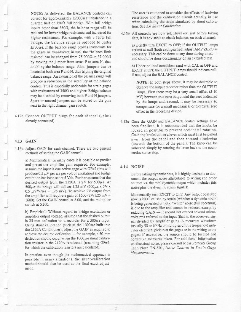
NOTE: As delivered, the BALANCE conFols canconect for approximately t20009,e unbalaace in aquarter, half or 350.f) full bridge. With full bridgeinputs other thafl 3500, the balance range will bereduced for lower bridge resistance and increased forhigher resistances. For example, with a l20O full
bridge, the balance range is reduced to under
t700p€. If the balance range proves inadequate forthe gages or tlansduce$ in use, the "balance limit
resistol' can be changed from 75 000O to 37 000O
by moving the jumper from areas P to area N, thus
doubling the balance range. Also, jumpers can belocated at both area P and N, thus tripling the originalbalance Enge. An extension of the balance range willproduce a reduction in the setability of ihe balancecon[ol. This is especially noticeable for stain gageswith resistances of 3500 and higher. Bridge balancemay be disabled by removing both P and N jumpers.
Spare or unused jumpers can be stored on the Pinsnext to the right channel gain switch.
4.12b Connect OUTPUT plugs for each channel (unless
already connected).
4.13 GAIN
4.13a Adjust GAIN for each channel. There are two generalmethods of setting the GAIN control:
a) Mathematical: In many cases it is possible to predictand preset the amplif,ler gairt required. For example,assume the input is one active gage with GF=2 (this willproduce 0.5 pV per pr,€ per volt ofexcitation) and bridgeexcitation has been set at 5 Vdc. Fufther assume that thedesired output from the 2120A. is 2V for 500tr€. At500p€ the bridge will deliver 1.25 mV (500ire x 5V x0.5 ttYN/p,e = 1.25 mV). To achieve 2V output fromthe amplifier will require a gain of 1600 (2Vl1.25 mV =
1600). Set the GAIN control at 8.00, and the multiplierswitch at X200.
b) Ernpirical: Without rcgard to bridge excitation oramplifier output voltage, assume that the desired outputis 25-mm deflectioo on a recorder for a 500p,e input.Using shunt calibration (such as the 1000t!€ built intothe 2120,4 Conditioner), adjust the GAIN as required toachieve the desired deflection - for example, a 50-mmdeflection should occur when the 1000&€ shunt calibra-tion resistor in the 2120.{ is selected (assuming GF=2,for which the calibration resistors are calculated).
In practice, even though the mathematical approach ispossible in many situations, the shunt-calibrationm€thod should also be used as the final exact adjust-ment.
The user is cautioned to consider the effects of leadwireresistance and the calibration circuit aclually in usewhen calculating the stmin simulated by shunt calibra-tion- See 5,0 Shunt Calibrstion.
4.13b All controls arc now set. Howevet just before takingdata, it is advisable to check balances on each channel:
a) Briefly turn EXCIT to OFF; if the OUTPUT lampsare not at null (both extinguished) adjust AMP ZERO asnecessary. This can be done at any time during a test -
and should be done occasiooally on an extended test.
b) Under no-load conditions (and with CAL at OFF ardEXCIT at ON) the OUTPUT lamps should indicale null;if not, adjust the BALANCE controt.
NOTE: In both steps above, it may be desirable to
observe the output recorder mther than the OUTPUI
lamps. First therc may be a very small offsec (5-10
mV) beMeen true zero outPul and the zero indicated
by the lamps and, second, it may be necessary to
compensate fot a small mechanical or electrical zero
offset in the recording device.
4.13c Once the GAIN and BALANCE contrcl settings havebeen finalized. it is recommended that the knobs belocked in positio[ to prevent accidental rotation.Counting knobs utilize a lever which must fust be pulled
arvc-v from the panel and then rotated clockwise(towards the bottom of the panel). The knob can beunlocked simply by rotating the lever back to the coun-terclockwise stop.
4.14 NOISE
Before taking dynamic data, it is highly desirable to doc-ument the output noise attdbutable to wiring and othersources vs. the total dynamic output which includes thisnoise plus the dynamic strain signals:
Momentarily tum EXCIT to OFF. Any outPut observednow is NOT caused by strain (whether a dynamic stainis being generated or not). "White" noise (full spectrum)is due to the amplifier and cannot be rcduced except byrcducing GAIN - it should not exceed several micro-volts rms refered to the input (that is, the observed sig-nal divided by amplifier gain). A recunent waveform(usually 50 or 60 Hz or multiPles ofthis frequency) indi-cates electrical pickup at the gages or in the wiring to thegages: if excessive, the source should be located andcorrective measures taken. For additional intbrmationon eleclrical noise, please consult Measurements CroupTech Note TN-50 | , ffoi.ve Cotltrcl itr Straitt GageMeasureuents.
- l t -
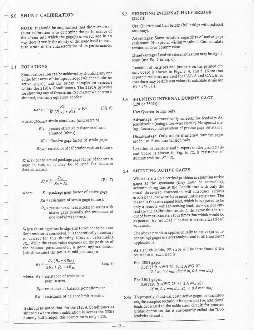
- 5.0 SHUNT CALIBRATION
NOTE: It should be emphasized that the Purpose of
shunt calibration is to ditermine the performance of
the circuit into which the gage(s) is wired, and in no
way does it verify the ability of the gage itself to mea-
,o.i ,ttuio or the characteristics of its performance'
_ 5.1 EQUATIONS
Shunt calibration canbe achieved by shunting any one
ofthe four arms ofthe input bridge (which includes an
active gage(s) and the bridge completion resistors
within ih; ?I20A Conditioner). The 2120A provides
for shunting any of these arms' No matter wbich arm is
shunted, the same equation applies: 5.3
pec^L=r( (Rc.rr. + Rir)
x 106 (Eq.6)
where: u€cAL: strain simulated (microstrain)'
R'a = precise effective resistance of armshunted (ohms).
&' = effective gage factor of strain gage.
RCAL: resistance of calibrationresistor (ohms)'
K may be the actual package gage factor of the straingug. in ur", or it may be adjusted for leadwire
desensitization:
K=K=+=^c r JiL
where: 1( = package gage factor of active gage.
Rc : resistance of strain Sage (ohms)'
RL = resistance of leadwire(s) in series withactive gage (usually the resistance ofone leadwire) (ohms).
When shunting either bridge arm to which the balance
limit resistor is connected, it is theoretically necessaryto correct for this shunting effect in determiningR'r,. While the exact value depends on the position of
the balance potentiometer, a good approxrmatlon(which assumes the pot is at mid position) is:
Re (Rr + 4RsL)p,' =
2 p ^ + f t s + 4 R e r
where: RA = resislance of resistor or
SHUNTING INTERNAL HALF BRIDGE(350o):
Use: Quarter and halfbridge (full bridge with reduced
accuracy).
Adyantages: Same resistors regardless of active gage
resistanci. No special wiring rcquired' Can simulate
tensiotr and/or comPression'
Disadvantage: Leadwire desensitization may be signif-
icant (use Eq. 7 in Eq. 6)'
Location of resistors and jumpers on the Printed cir-
cuit board is shown in Figs. 3, 4, and 5' (Note that
seDarate resistors are used for CAL A and CAL B, so
th;t these may be different values; to calculate strain use
Ri = 349.3()).
SHUNTING INTERNAL DUMMY GAGE(120 or 350O):
Use: Quarter bridge onlY.
Advantaqe: Automatically corrects for Ieadwire de-
sensitization (using three-wire circuit) No special wir-
ing. Accuracy independent of precise gage reslstance'
Disadvantage: Only usable if intemal dummy gages
are in use. Simulates tension only'
Location of resistors and jumpers on the printed cir-
cuit boatd is shown in Fig. 6 Ri is resistance of
dummy resistor. K= K'
Ri
gage rn arm.
. Rp = resistance of ba.lance Potentiometer'
RBL = resistance of balance limit resistor'
It should be noted that, for the 2120A Conditioner as
shipped (where shunt calibration is across the 350Odummy half bridge), this correction is or.ly 0'2Vo'
5.4 SHUNTING ACTIVE GAGES
While there is no electdcal problem in shunting activeqaees al the specimen (they must be accessible)'
iciomplistring this at the Conditioner with only the
usual ihreelead connection will introduce sedous
errors ifthe leadwires have measurable resistance' The
reason is that one signal lead, which is supposed to be
onlY a remote voltage-sensing lead, now carnes cur-
reni (to the calibration resistor); the error thus intro-
duced is approximately fourtimes that which would be
expected"by normal "leadwire desensitization"equatrons.
The above problem applies equally to active (or com-
pensating);ages instress analysis and to all transducer
applications.
As a rough guide, 170 error will be introduced if the
resistance of each lead is:
For l20O gages:0.30 (t ft AwG 26, 30 ft Awc 20)
i2.l ^, 0.4 ̂ ^ dia; 9 m, 0'8 mm dia)
For 350O gages:0.90 (20 ft AwG 26, 85 ft AwG 20)
i6 m, 0.4 mm dia; 25 m, 0'8 mm dia)
5.4a To properly shunt-calibrat€ active gages or transduc--' -
".t,ift. u..tpted technique is to provide two additional
leais dedicated to the calibration circuit; for quarter-
L.iOg. op.t"tion this is customarily called the "five-
leadwire circuit".
(Eq. ?)
(Eq. 8)

CHANNEL
CAL A: Tension (+)CAL B: Compression (-)
NOTE: This is standard configurationof the 21204 as shipped.
Fig. 3: CAL on Internal Ealt Brfulge (Tension and Compression)
CHANNEI
fi)
9
(x )
+i i-] l'T'[i"*,-
L_lil,fu^Iilff ' l
P- ;REM E
lril'--r{ I :::LJ I i ii!.1=:-:.3+il+i l$"[.;';'[
c-1 t666r- P.l nrm I
t-li i*l'T:{t? l---: " *fi3rJ"
IHTT)il
CAL A & B: Tension (+)
Fig. 1: CAL on Internsl HaA Bridge (Tension)
],*,,,",,
l,*.,.
\a/
o
o
@
!ii,$,*ttntiitii.r.iiilfi ,$"{.$'{'{l*itl,[? l-.: ^ H3-i.
IHIli[1iL_l/ K 3
- 1 3 -

|,*,,-",,
IJ,'*.."
CAL A & B: Compression (-)
Fig. 5: CAL on Internal EaA Bridge (ComPression)
( x )
o
o
o
( x )
+r-r i-l u'T'll"*,-
L-ll l$r^lit'. l
P - ;REM d
lrfrtr,{l:::r-'r Ti id.l=:-:-:+ilFr jt"[i'i.i
;i:ulvn
IHT
K3
l)r
Fig. 6: CAL on Dummy Rxistor
1,,,,,.,.,,-,,J *'," **-',
1,,,*..,,_,J o'" *'*-'
(x)
o
o
o(x )
+! i-l u'T't$,*,-
L-JL i#;^r#n P - ; x € M ;
/rfrrr,{:::lqr T i i^:.3=:,:-[ililili t$"{.{T.{
a oooooo, P+ o.- B
lill$'T?{t?:---i ^ H3","
IEI
K3
T)F
CAL A & B: Tension (+)
- 1 4 -

SOTDER PADS S & T ARE CLOSED (FAR SIDE) A
l e t
t f
CALA&B:Compression (-)
CTOSED (FAR SIDE)
t l
l A lB
CALA&B:Tension (+)
Fig. 7: CAL on Active Gage (Tension or Compression)
CHANNEL
CHANNEL
a
o
o
(x)
lii,Nfl'ntiltii.l.lililli :$"1'$'1.{
;1. ffi$
]En
K3
Tln
SOLOER PADS S&T ARE
RIGHTCHANNEL
' No vacant pin available. Hemoveexisting wire and use Pin G, H, or F.
CAL A: Tension (+)CAL B: Compression (-)
B
t l
l l
A
Fig. 8: CAL on Active Gage (Tension and Comptession)
CHANNEL
SOLDER PAD T IS CTOSED (FAR SIDE)
PAD T ls ct-osEo (FAR slDE)
(x )e"t r-eY9,l'r/
B
?e6699
e6 adY Y
66?9dd
-;
6 l o
r5i- l ^\dT
L_lr i,4+t1al
P- ;REM
trilt:,{ I I! li il3.3_lililill ,$"1"$
a ooo\J
P- T REM
nil*#.8I l i i E/; , 'l:--) ^/a.X1
IHT
K3
!)r
- 1 5 -

Pins J and K on the inPut connector are used for this
aDDlication. Figures 7 and E show a halfbridge, butthecal.ibration wiring also applies to full bridges and
transducers; for true quarter bridges, Fig' 7, compres-sion onlY, aPPlies.
The added external leads should be connected directlyto the strain gage terminals. Ri = actual gage resis-tance. r( = K' (In a transducer, the connection shouldbe made at the connector on the transducer' .Ri wouldbe the effective resistance of the shunted trans-
ducer arm.)
5.5 OPTIONAL REMOTE.OPERATION RELAYS
Four isolated relays can be provided to operate thefollowing functions in tbe 21204:
Shunt Calibration (A and B)Bridge Excitation off (to check amplifier
zero or electrical noise)
While the relays are not installed unless sPecified at thetime of order, they can be easily installed later by aoualified techniciaq all wiring already exists in the2^120A module' For after-sale installation, order relaykit sel€cted from Table 5.1.
5.5a An external dc power supply is required to control the
relays in the 2120A modules. Remote-operalion capa-bility must also be specified for th€ Model2150 RackAdapter or Model 2160 Portable Enclosure' The sys-tem would be wired as shown in Fig. 9.
2150 0l 2160AS MOOIIIEO FOR REA4OT' OPERATION
2120aAMPUFI€R(5)
Fig. 9: Remote'OPeration Wiring.
Table 5.1
OPTIONOPERATINC
VOLTAGE
REQUIREDCURRENT FORTWO.CHANNEL
MODIJLf,
PARTNUMBER
I )
Y24
5Vt2v24v
90 ldA75 mA50 rnA
120{01338120.001339120401330
- 1 6 -

6.0
6.1
SERVICING DATA
CUSTOMER MODtr'ICATIONS
There are three simple modifrcations that can be made to
suit specific measuremeot requiremelts. However, it
should be noted that these modifications may, to someextent, affect overall Performalce:
a) Shunt-calibration dircuit. See 5.0 SlruztCdlibrction.
b) Change bridge BALANCE range: See 4.124.
c) Change bandpass: As shipped the 2120A is config'ured for a bandpass of 15 kHz (-3.0 dB). Bandpasscan be increased to 50 kHz by removing jumper R.Spare jumpers may be stored on pios next to gain
switch.
SERYICING
Individual schematics of the vadous modules are includ-ed on the following pages. To facilitate service,3-ft(0.9-z) extension cables are available to operate themodules outside the rack or enclosure:
15-pin (for 2120A) PAI200-13059625-pit (for 2110N2111) P/N 200-130597
FIELD.REPLACEABLE COMPONENTS
It is rccommended that a defective module be retumed tothe Measurements Group for repair and recalibration inorder to preserve the factory warranty. At the €xPimtionof factory waranty, user organizations with qualifiedelectronic technicians and suitable calibration facilitiesmay choose to repair the units by refening to circuitdescriptions, int€rnal adjustment procedures and sche-matic diagrams.
The components on the following list are those which
may be required in the repair of a defective amplifier
Other components may be obtained from the Measure-ments Group by reference to the schematic designationand the serial number of the amplifier. Consult Mea-surements Group Applications Engineering DePartmentfor assistance.
2111 DC.OPERATED POWER SI]PPLY
Description
Meter, Bridge Volts
Integroted Circuits:Regulator
(National, LM723CN)
Diodes and Rectif.en:Diode, Rectifier
(Motolola 1N4002)Diode, Rectifier
Motorola 1N4004)
Transistors:Transistor, NPN
(Motorola TIP-3055)
Coflnector, Power InPut
Meter, Bridge Volts
DC-DC Convefter
DC-DC Converter
2110A POWER SUPPLY
SymbolMI
U1.U3
cR1-CR17
cRl S
Q1-Q3
P/N
200-130s83
14X700040
14X400135
14X400088
t4x200t9l
] . .
l- 2120A STRAIN GAGE CONDITIONER
M 1
z122
u2
U3, U4
U5
U6
u7
cRl
cR2-CR5
Q l
Q2
Q3
Q4
12X300606
200-130583
26X100190
26X100191
12X300515
12X3005s6
14X700153
14X700040
t4x't00162
r4x700096
l4x700l l8
14x700087
14x500108
14x500107
14x200189
14X200183
14x200184
14x200i90
6.2
Input Plug
Output Plug
Integrated Circuits:Regulator
(National, LM337LZ)
Regulator(National. LM723CN)
Amplifier(PW OV21EZ)
Amplifier(PMr, OP01CP)
Amplifier(PMI, OPI5EZ)
Amplifier(PMI, OPOTDP)
Diodes dnd Rectifiers:D'iode, Refercnce
(National. LM3362-5.0)
Diode, Zener 13V(Motorola. IN4743)
Trsnsistors:Transistor, NPN
(Motorola, MJE52l)
Transisto( NPN(Motorola, MPS8099)
Transistor, PNP(Motorola, MPS8598)
Transistor, PNP(Motorola, MJE37l)
6.3

6.4 INTERNALADJUSTMENTS
If equipment malfunction occurs during the warranty
period, the defective unit should be retumed to the
Measurements GrouP in order to Preserve the factory
warranty. The following adjustment Procedures are
intended to aid the technician in the proper adjustment of
the ampl.ifier in the event that compolents are changed
during tloubleshooting and repair of the unit subsequent
to the warranty Pedod.
6.4a 21104 Power Supply Adiustrnents
Set line voltage switch to corresPond with operating
voltage. (See 4.lD)
Switch power to ON.
Place DVN{ probes across C 1 1 .Adjust R6 for output voltage of+15V tl7o.
Place DVM Probes across C12.Adjust Ri 1 for outPut voltage of -l5Y xlVo
Place DVM plobes across C14.Adj ust R I 6 for outPut voltage of + 17.5v tl 70.
6.4b 2111 DC-Operated Supply Adiustment
tl5V outputs are fixed bY design.
Switch power to ON.
Place DVM probes across C5.
Adjust R6 for output of +17 .5V tlEa-
6.4c 2120A Amplilier Adiustnents
Ulless otherwise specified, an inPut connector with S+,
S- and Gnd terminals shorted together must be con[ect-
ed to the amplifier input for all the following tests.
Repeat procedure for both left and right channels.
NOTE: Allow 30'minute warm-up before making
final adiustments.
Zero Adjustments
Set EXCIT switch to OFF.Set Gain Multiplier to X200 and Potentiometer to 10.50(Gain = 2100).Connect DVM from TPt to Pin 2 of output connector(t2).Set front-panel AMP ZERO control R20 8 turns clock-wise from full counterclockwise position.Adjust R13 for DVM reading of zero ai00 PV.
Set Gain Multipl.ier to X2'Adjust R23 for DVM reading of zero t1 00 pt V
Check and adjust zeros of R13 and R23 until there is nozero shift when switching between gain ranges of X2and X200.
Move DVM ftom TPI to Pin 3 of outPut connector.Adjust R29 for reading of zero *1 mV.Both BALANCE LED's should be extinguished.
Common-Mode Adjustment
Connect oscilloscope to Pins 3 and 2 of the outputconnector.
Apply 60 Hz, 10V p-p sinewave from (S+, S-) to Gnd oninput connector.
Set Gain Multiplier to X2.Set Gain Potentiometer to X10.5.
Adjust R21 for minimum oscilloscope deflection.60 Hz deflection should be less than 7 mV
SCIIEMATICS
Schematic diagrams for the 2il0A Power Supply' 2l1lDC-Operated Power Supply,2120A Stra in GageConditioner, 2150 Rack Adapter and the 2160 PortableEnclosure are found on the Pages that follow.
6.5
- 1 8 -
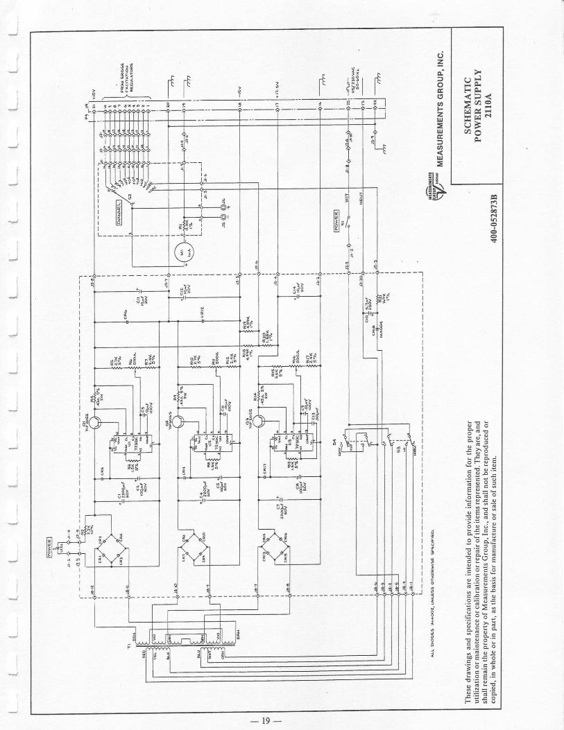
| \ t . l
F A<p<>qa9ETFUEt h o
F
9 - oi 6 r
i l j E
n > 6l i E ;€ I P E
iEaEE ! J - L
: a i or i o E oc e a =' ' 2 n i ;gEE6o o c i ;
6 eis z-i e E d Ed y iEiI : r : - :f i .E: E!E veEZi I: ; :1 . eeeEi .E: i Fi E g;E{ ! o . : : : *
E ; E 3=q € .E a6: pE€t. ; b . = ;! i q E c
: t 9 dqE? 3.t r =+ 3
o=
c
oFz!,1=ut
otrj=
* t E
riN\'z'd/
- t 9 -

FT
"1 =
5 l ( - 'E F I FE 'o *
<
! d E
re gE
Ef;E;: a " o
JE ; Ea ; JeEEEz9E +E! 6 F Etg ,5Eq L . 9 LE o c . o
; E E;eE4i ,
. 9 4 ' d
EE l i s5 : o . j
gEiE- E E e
eE€€t E.=EI iE ;sEe'&t r 3E 3
z
at,Fz=ul
4,,
UI=
! t t
6>\'iE!/
.t
a i i
6 ^Y
* g2
i .-----------.^---].
T1
mu 1
E]
I
Uz9o 0 h6 \ \
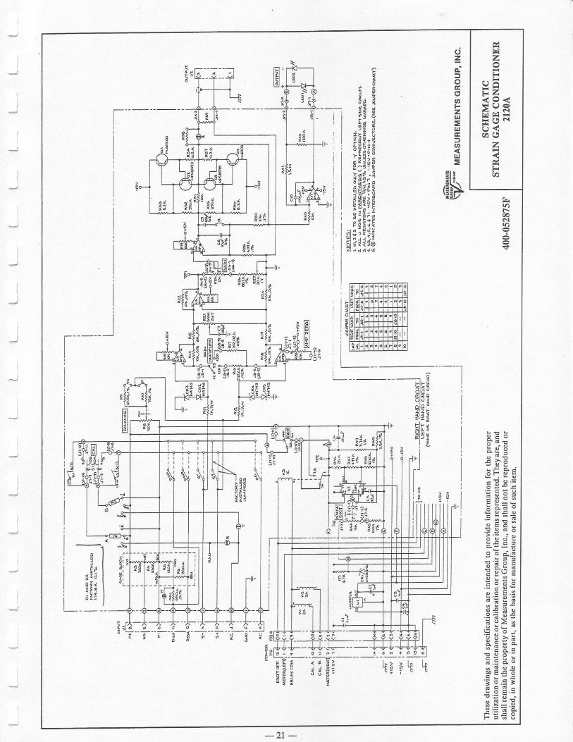
zF
e6Ez<o<>9REEFo<c h o
z
FTA
t00e.l
9 E o* r t E
r i " " . ;e i I E
Eee;E F=:' - 2 E i ;
SE€5
eE d"ErF3?
.E 9 5€
E i4 ; ,. : G 1 9 i; 9 2 e
EPNIa E R c
:gi;SE€I' t 5 .E ;! 6 F E c
lE9 ;4 . ! = . 9
FE'H S
o=d
G,
atF2|rl=tu
at!J=
Et iE+\\tEil
E!
1I
g2t
EiE, ^ 2" . i ! .
E4gEi 4
A"iE,,EE-,ii63"^i tF.zit "i
Efl,i?gEHUiT. "zE; ii \E:u
sils: P $H8-.4ig,6
tet
telEJ.
6
!
t
tutEllil
$i!i
i
II
II
'I
3 lf f I
t t ; Ia a ! |: ! i I
L
---Er
clsslq
EIP
s|E4iTltIl
l l l l cl l l iJ .
.;l-;---1 a E , ;u v i .g
l rh__5_i-_'_
Ira a\ i i
r i 9
-2 t -

9 - o
! ! , E
, ;i asU - E a . e -
4 .E! i *4 E92Al - E 9 - e; : a ; o; d q E o
q - ! ! i ;
: €EEE3 : ; Jek a tE?
s :E *r! ! 30EN h : d :
: 5 E 5^ ^ c 6t a e 2
e E 2 a.e t !€E _: - *!C is4 ; ; c
! q o :E.E E .59E€I' i b .E ;F E F cITE;
iE+ A
ct=e
oEa5anFz!t
ul
loulE
$
irlril
t
t39i9Y
tt)
U]0l uiL
Nl Sroo
t
I
;
634
F J
7J
\(t
oL
qn
H'{a y
fr79t
7o
iz'C6
n
l
t,l
i
I
lr
4 u t
4 4 ' ,
2I
<!o O
''-,9
''
.l
t-F ]l E )l 3 lr N ti F il € ll e ,t E ll J 'l 4 ll s lt t ,i c >
i i g i. Il l 6 Il F lJ l . 5 I
- {t i " r
\0.(!2
$oo
9i z
9Et-xYtt
l*
\c
e r =a 4 ;Fract<F iE?YHAEi" < r'r;xH
< i
9r

WARRANTY
Measurements Group, Inc., warrants all instruments it manufactures ro be free from defect in materials and factory workmanship, and agrees
i" ,.p"ir "r
t"pf""" #y insuument thar fails to perform as.specified within three years after date.of shipment Coverage ofcomputers' calll-
"iur-,',""t alg"'uUf. Ourlries. a.nd simi.lar items, iold in conjunction with equipment manufacrured by Measurements Croup' lnc and bearing
,fr" ij""iiir,-i,,rg name of another company, is limited under this warranty !o one y"* aftef the date of shipment' The warranly on non-
rechaEeable barteries and similar consuma'ble iterns is limited to the delivery of goods free ftom defects in materials and factory wolkman-
ship. fhis warranty shall not apply to any instument that has been:
i) reDaired, worked on or altered by persons unauthorized by the Measuremenrs Group itl such a manner as to injure, in our sole
juigment, the performaoce, stability' or reliability of the instrument:
ii) subjected to misuse, negligence, or accident;
OT
iii) connected, installed, adjusted, or used otherwise than in accordance with the insffuctions fumished by us.
At no charge, we will repair, at our plant, Or an authorized rePat station, or at our option, rePlace any of our ploducts found to be defective
under this warnnty.
This warranty is in lieu ofany other warranties, expressed or implied, includine anv implied warranties of merchantability or fitness
for a particular purpose, There are no war.anties which e*tentt beyond the deicription on- the face.hereof' Purchaser acknowledges
in"fJi !oo* pui"ftased fro- Measurem".t" Cro,rp "."
p,r""hased'as is, and buyei states that no salesBan' agent, employee or other
person has made any such representations or lnarrantiei or otherwise assumed ior MeasureEents Group any liability in connection
i"iifrin" ,"f" of ".ty
gooas to itre po"ctr"s"" foye" tt"t"ty toaives all rights buyer may have arising out of any- breach of contract or
;;;;;;i;;;;".ty "on the part of Meas,r."-"nts c"oop, to any inciilintal oi consequential damages, including t'ut not limited to
a"-"g". to prop"ity, aamales for irrjrrry to the person, iamages for loss of use, loss o1time, loss of profits or income, or loss result'
ing from personal injurY.
some states do not allow the exclusion or limitation of ilcidental o! consequential damages for consumer products' so the above limitations
or exclusions may not aPPIY to You.
The purchaser agrees that the Purchaser is responsible for notifying any slbsequent buyer of goods manufacturedty Measulements Group
of rhc warranty provisions, Iimitarions, excluiions and disclaimeri staied herein, prior to thJtime any t::l!o-o-d:.*" put"hased by such
buyer, and the Purchaser hereby agrees to indemnify and hold Measurements Group harmless from any claim asserted against or liability
imoosed on Me$uremenrs Croup occasioned by the'failure Of the Purchaser ro so noiify such buyer This provision is not intended to afford
t"'fr"q*nf p*ahot"" any warranties or rights not expressly granted to such subsequent Purchasers under the law'
The Measuremenrs Group reserves the right to make any changes in the design o! construction ofits instruments at any time, without incur-
ring any obligation to make any change whatever in uoits prcviously delivercd'
The Measurements Croup,s sole liabilities, and buyer's sole remedies, under this agreement shall be.limited lo the Purchase price. or al our
sole discretion, to the repalr Or replacement Of any instrumeot that proves, upOn ex-amination, tO be defective, when retumed tO our fadOry'
transportation prepaid by the buyir, within the applicable period of time from the date of original shipmeol
Retum transportation charges of rcpaired or replacement insbuments undel warranty $ ill be prepaid by Measurements Group, Inc'
The Measurements Group is solely a manufacturer and assumes no responsibility ofan! fb[m for the accuracy or adequacy of any test results'
da!a, or conclusions which may result from the use of its equipment.
The manner in which the equipment rs employed and the use to which the data and test results may be put are comPletely in the hands ofthe
pu."haser Measu."menr, Group, lnc,, shail in no way be liable for damages consequential or incidental to det'ects in any of its products'
This wananty constitutes the full undelstanding between the manufachrrer and buyet and no terms. conditions. understanding, or agreement
purporting to modity or vary the terms hereoi shall be binding unless hereaftei made in writing and signed by an authorized official of
Measurements Croup, Inc.
-23 -
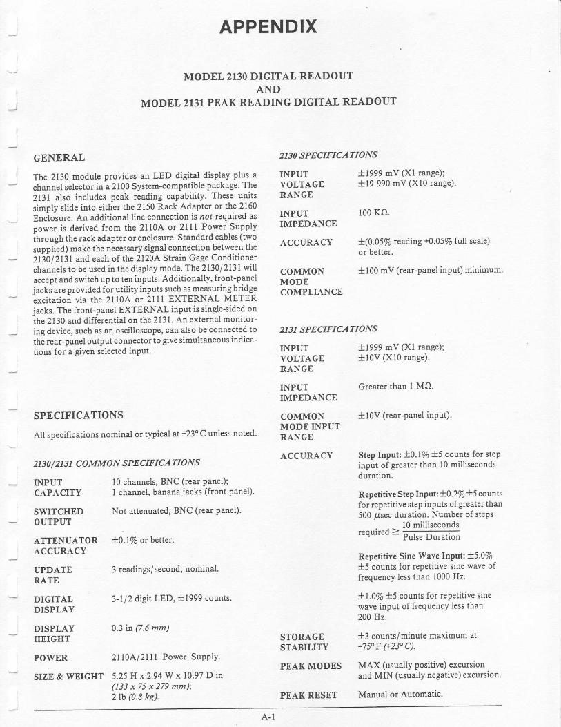
APPENDIX
MODEL 2130 DIGITAL READOUTAND
MODEL 2131 PEAK READING DIGITAL READOUT
GENERAL
The 2130 module provides an LED digital display plus achannel sel€ctor in a 2100 System-compatible Package. The2131 also includes peak reading capability. These unitssimply slide into either the 2150 Rack AdaPter or the 2160Encloiure. An additional line connection is no, required asoower is derived from the 2110A or 2ll1 Power SupPlyihrough the rack adapter orenclosure. Standard cables (two
supplied) make the necessary signal connection between the2l1O t2l3l and each of the 2120A. Shain Gage Conditionerchannels to be used in the display mode. The 2130/ 2131 willaccept and switchup to ten inputs. Additionally, front-paneljacks are providedfor utility inputs such as measuring bridgeixcitation via the 2ll0A or 2lll EXTERNAL METERjacks. The fronhpanel EXTERNAL input is single-sided onthe 2130 and differential on the 2131. An external monitor-ing device, such as an oscilloscope, can also be connected tothe rear-panel output connectorto give simultaneous indica-tions for a giveu selected input.
SPECIFICATIONS
All specilications nominal or typical at +23oC unless noted.
2130 / 2 1 3 1 CO MMON SPECIFICATIO NS
10 channels, BNC (rear panel);I channel, bananajacks (front parel).
Not attenuated, BNC (rear Panel).
ATTENUATOR t0.l% or better.ACCURACY
INPUTCAPACITY
SWITCHEDOUTPUT
3 readings/second, nominal.
3-l/2 digit LED, i1999 counts.
0.3 tn (7.6 mm).
2ll0Al2lll Power SupPlY.
2130 SPECIFICATTONS
INPUTYOLTAGERANGE
INPUTIMPEDANCE
ACCURACY
COMMONMODECOMPLIANCE
2131 SPECIFICATIONS
INPUTVOLTAGERANGE
INPUTIMPEDANCE
COMMONMODE INPUTRANGE
ACCURACY
STORAGESTABILITY
PEAK MODES
PEAK RESET
t1999 mV (Xl range);tl9 990 mV (Xl0 range).
100 Ko.
t(0.0516 reading +0.0570 full scale)or better.
tl00 mV (rear-panel input) minimum.
ti999 mV (Xl range);tl0V (X10 range).
Greater than I MO.
t10V (rear-panel input).
Step Input: t0.l/6 t5 counts for stepinput of greater than l0 millisecondsduration.
Repetitive Step Input:10.2/s *5 countsfor repetitive step inputs ofgreaterthan500 usec duration. Number of steps
_^^..:--r -> l0 millisecondsrequired 2 Pulse Duration
Repetitive Sine Wave Input: 45.0/6t5 counts for repetitive sine wave offrequency less than 1000 Hz.
X|.\Vo X5 counts for repetitive sinewave input of frequency less than200 Hz.
t3 counts/minute maximum at+750F (+230 C).
MAX (usually positive) excuffionand MIN (usually negative) excursion.
Manual or Automatic.
UPDATERATE
DIGITALDISPLAY
DISPLAYIIEIGHT
POWER
SIZE & WEIGHT 5.25 H x2.94Wx 10-97Din(133 x 75 x 279 mm);2 tb (0.8 kg).

2130/2131 REAR VIEW
CONTROLS
OUTPUTDISPLAY
CHANNELSelector
EXTERNALJacks
''- ATTEN Switch
POWER Switch
SIG OUT(Rear Panel)
Provides a digital reading of the inputas selected by CHANNEL selector.Typically used to monitor strain orbridge voltage.
Positions I to l0 select the input chan-nel for display. (Cenerally, position Iis channel far thest to the le f t inrack, etc,)
The EXTERNAL position selects theinput that is connected to the adjacentfront-panel jacks.
Provide ability to accept a front-panelinput, typically bddge voltage from2tr0 Al 2rtl EXTERNAL METERjacks
Xl position gives t2 volt range.
Xl0 position gives t20 volt range(tlOv for 2131).
This switches the 17.5 vdc Powersupply. The pilot lamp LED indicateswhen power is on.
BNC receptacle used to monitor theinput signal on an external indicatinginstrument such as an oscilloscope.The desired channel is selected withthe front-pauel CHANNEL selectorswitch.
Inout Connectors l0 BNC receptacles (typ. connected(Rear Panel) to 2120.4, OUTPUT receptacles).
RESET Switch€s AUTO (Toggle Switch) - When set(213f) to AUTO, the stored peak reading'
is periodically reset to the existinginput level. Automatic reset willoccur aPProximatelY everY 5 to l0seconds.
MAN (Push-button Switch) - When
Pressed, resets Peak reading to theexisting inPut level; the button shouldbe held 1 second or more fot a com'
Plete reset.
PEAK MODE ON-Display reads the stored peakSwitches (2131) reading. When off (down), display
reads the existing inPut level.
MAX - The most positive (algebraic)input is stored.
MIN - The mosi negative (alSebraic)input is stored.
I
I
SETUP
Install the 2130/ 213 I into the rack or enclosure as discussedin 4.0 Operating Procedwesi the 2130l2l3l is installed inexactly the same manner as the 2120A Conditioners' fillingone of the rack or enclosure slots.

INPUT CONNECTIONS
Connect the OUTPUT connector ofeach 2120A channel to
be displayed to the appropriate 2130/ 2l3l input, preferably
using the standard cables, two of which are provided (Mea-
surements Group No. 200-130827, accessory 2130'A27). lf
necessary, a cable can be made as d iscu ssed h 4.6a and 4.6b;
connect the 2120A OUTPUT (pin 3) to the centerBNC pin
and the shield (pin 2) to the BNC shell.
If desired, bridge voltage can be displayed by connecting
banana plugjumpers between the 2l l0A/21 I 1 EXTERNALMETER jacks and the 2130 | 213 I EXTERNAL jacks (con-
nect red to red and black to black).
OPERATION
To prevent damage to small gages orsensitive galvanome-ters, before turning on power to the 21l0Ai 2lll and213012131, complete all steps in 4.0 Operating Proceduresthrough y'.9e.
Turn POWER on to both the 2110A/21I I and 2130/ 2131.Set the 2l3l PEAK MODE and RESET-AUTO switches tooff. Continue on y'.10 utilizing the CHANNEL selector tochoose the desired channel for display. Observe the OUT-PUT DISPLAY when adjusting the 2120A balance and gaincontrols as well as when taking data. For convenience, theOUTPUT DISPLAY may be set up to read directly inengineering units.
The AfiEN switch is normally used in the Xl position butthe X10 position is required when lhe reading goes over 1999counts and the display flashes (indicating oYerrange). In theXl mode, the 2130/ 2l3l reads directly in millivolts (tens ofmillivolts in the Xl0 mode).
To use the 2l3l without utilizing the peak reading feature,keep the PEAK MODE and RESET toggle switches set tothe off (down) position. To take peak rcadings using the2131, achieve desired calibration as discussed in the aboveparagraphs and proceed as follows depending upon type ofinput signal:
NON.RECURRING PEAKS
. Set RESET-AUTO to off (down position).
. Set PEAK MODE rotary switch to MAX and theroggle switch to ON.
r Press RESET-MAN firmly (approximatelyI second).
a Load specimen or structure through the peakvalue of interest.
r Read OUTPUT DISPLAY.
If the MIN peak is of interest, turn PEAK MODE to MINand press RESET-MAN again.
NOTES
In both MAX and MIN modes, a peak reading can haYeeither a positive or negative sign. For example, if RESETresults in a +1500 court reading (static load offset), a -440
count input excursion from the offset level will result in areading of+ I060 in the MIN mode or an unchanged readingof +1500 in the MAX mode. If instead th€ excursion were+200, the reading vr'ould have been an unchanged +1500 inthe MIN mode or +1700 in the MAX mode.
A very slow display change can be due to Peak storage driftthat is not necessarily due to change in the strain amplitude.Typicallythe MAX peak storage can drift in either direction,whereas MIN peak storage tends to drift in the positive
direction.
Io the presence of 50/60 Hz pickup, the display wil l readslightly higher in peak reading mode because the pickup
appears to the 2l3l as a normal (although small) dynamicsignal. Therefore, this pickup should be minimized by usingtwisted and shielded strain gage input wiring.
RECURRING PEAKS
. Ser PEAK MODE toggle swrtch to off (down position).
. Establish static load (if required) and cyclic load.
o Set PEAK MODE to ON.
. Switch RESET to AUTO.
o Press RESET-MAN firmly (apProximately I second) orwait for automatic reset to reset display.
. MAX or MIN should now be displayed according tothe position of the PEAK MODE control.
. To read the opposite peak, set PEAK MODE rotaryswitch accordingly arld repeat prior two steps,
o To determine the peak-to-peak amplitude, algebraicallysubtract the MIN reading from the MAX reading.
. A decreased cyclic strain amplitude will be reflectedh the display after reset occurs'
SERVICE
A schematic of the 2130 and the 2l3l can be found on thenext page. Replacement parts cafl be obtained from thefactory.
There is an internal adjustment in the 2130/2131 for spansensitivity. Tbis can be tt immed by applying exactlyt 1.900V to the input arld adjusting the potentiometer at rearof meter unti l readout displays a1900. A five-minute warm-up is recommended.
A-3
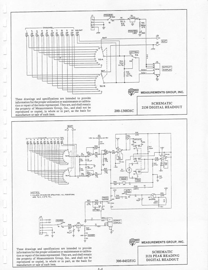
F6qEFr
6
F'rrPUr IID1SFLAYI
F|'JF uelsunEMENTS cRoup, lNc.
The6e drawings and specifications are intended to provide
information foi theproptrutilization or maintelance ol calibra-
tion orrepairoftheitems reprcsented. TheJ arc, and shall remajn SCHEMATIC2I3O DIGITAL READOUTlhe prop;rty of Measurements Group. lnc, and shal l not be
.ep-duced-o" copied, in whole or in part, as the bssis for
minufacture or sale of such item.200-r30826C
NOtESI
W MEASUREMENTS GROUP' INC.
Tlese drawings and specificatiotts arc intended to provide
information foi the proPer utilization or mailtenancc orcalibra-
tion or rcpair of the items reptesented. They arc' an{ 1ta].f rema,tnSCHEMATIC
213I PEAK READINGDIGITAL READOUTrbe propirty of Measuremlnts Group, Inc..4nd shal l oot be
,ap.odu""d'o. copied, in whole or in part, as rhe basis for
manufaclure or sale of such ilem300-045251G
L-A