Automatic Measurement of Payload for Heavy Vehicles Using Strain Gages
Upload
hareesha-n-gowda-dayananda-sagar-college-of-engg-bangaloreCategory
view
2.987download
4description

Unit-1: Electrical Resistance
Strain Gages
Hareesha N G
Asst. Professor
Department of Aeronautical Engineering
DSCE, Bengaluru-78

SYLLABUS
UNIT-1: Electrical Resistance Strain Gages:
• Strain sensitivity in metallic alloys, Gage construction,
Adhesives and mounting techniques, Gage sensitivity
and gage factor
• Performance Characteristics, Environmental effects.
• Strain Gage circuits, Potentiometer.
• Wheatstone’s bridges, Constant current circuits
06 Hours
8/27/2013 Hareesha N Gowda, DSCE, Bangalore-78 2

STRAIN-GAGE ALLOYS
• A list of some metallic alloys commonly employed in commercial
strain gages, together with their sensitivities, is presented in Table.
8/27/2013 3Hareesha N Gowda, DSCE, Bangalore-78

1) Constantan
• Most electrical-resistance strain gages produced today are
fabricated from the copper-nickel alloy known as Advance
or Constantan.
8/27/2013 4Hareesha N Gowda, DSCE, Bangalore-78
Fig: Percent change in resistance as
a function of percent strain for
Advance alloy.
A typical curve showing the
percent change in resistance
ΔR/R as a function of percent
strain for this alloy is given in
Fig.

1) Constantan
• This alloy is useful in strain-gage applications for the following reasons:
– The value of the strain sensitivity SA is linear over a wide range of strain, and the hysteresis of bonded filaments is extremely small.
– The value of SA does not change significantly as the material goes plastic.
– The alloy has a high specific resistance.
– The alloy has excellent thermal stability and is not influenced appreciably by temperature changes when mounted on common structural materials.
– The small temperature-induced changes in resistance of the alloy can be controlled with trace impurities or by heat treatment.
8/27/2013 5Hareesha N Gowda, DSCE, Bangalore-78
2) Iso-elastic Alloy• The Iso-elastic alloy is also employed in commercial gages
because of its high sensitivity and its high fatigue strength.
• The increased sensitivity is advantageous in dynamicapplications where the strain-gage output must be amplifiedto a considerable degree before recording.
• The high fatigue strength is useful when the gage is tooperate in a cyclic strain field where the alternating strainsexceed 1500 με.
• In spite of these two advantages, use of the Iso-elastic alloy islimited because it is extremely sensitive to temperaturechanges.
• Iso-elastic gages can be used in dynamic applications onlywhen the temperature is stable over the time required for thedynamic measurement.
8/27/2013 6Hareesha N Gowda, DSCE, Bangalore-78

3) The Karma alloy
• The Karma alloy has properties that are similar to Advance alloy.
• Indeed, its fatigue limit is higher than Advance but lower than
Isoelastic.
• In addition-Karma exhibits excellent stability with time and is
always used when strain measurements are made over
extended periods (weeks or months).
• Another advantage is that the temperature compensation which
can be achieved with Karma is better over a wider range of
temperature than the compensation which can be achieved
with the Advance alloy.
• Finally, Karma can be used to 500°F (260°C) in static strain
measurement whereas Advance is limited to 400°F (204°C).
• The primary disadvantage of Karma is the difficulty in soldering
lead wires to the tabs.8/27/2013 7Hareesha N Gowda, DSCE, Bangalore-78

4) The other alloys
• The other alloys, Nichrome V, Armour D, and the platinum-
tungsten alloy are metallurgically more stable and
oxidation-resistant at higher temperature.
• These alloys are used for special-purpose gages which
permit measurements strain to be made at temperatures in
excess of 500°F (260°C).
8/27/2013 8Hareesha N Gowda, DSCE, Bangalore-78
Fig: Thermally induced
apparent strain as a
function of temperature
for three common strain-
gage alloys.

STRAIN GAGE TYPES AND GAGE CONSTRUCTION
Wire strain gages
– The unbonded wire strain gage
– The bonded wire strain gage
– Weldable wire gages
Foil strain gages
– Weldable foil strain gages
8/27/2013 9Hareesha N Gowda, DSCE, Bangalore-78
8/27/2013 Hareesha N Gowda, DSCE, Bangalore-78 10
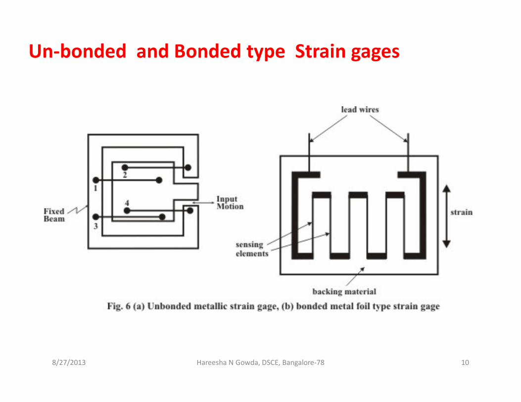
Un-bonded and Bonded type Strain gages

Un-bonded type wire strain gages
• One of the early wire gages was the unbonded type.
• In this type of instrument, the strain-sensitive wire is mounted, under tension, on mechanical supports (pins) in such a manner that a slight relative motion of the supports will cause a change in strain.
• This, in turn, produces a change in electrical resistance.
• This resistance change is then a measure of the relative displacement of the supports and, in turn, may represent a strain or some other quantity.
• With the unbonded type of gage, the fact that the strain-sensitive wires must be carried on some sort of mechanical mount gives rise to certain difficulties in connection with attachment.
8/27/2013 11Hareesha N Gowda, DSCE, Bangalore-78

Bonded-wire strain gages
• The first major improvement in the wire resistance strain
gage came with the realization that many of the
difficulties with the unbonded wire gage could be
eliminated by bonding a very fine strain-sensitive wire
directly to the surface on which strain is to be measured.
• The filament has to be electrically insulated and the
bonding perfect for the strain-sensitive element to follow
the strain on the surface to which it is attached.
• Most bonded wire strain gages are made from wire of
approximately 0.001 in diameter, or less, and in
resistances varying from about 50 ohms to several
thousand ohms.
8/27/2013 12Hareesha N Gowda, DSCE, Bangalore-78

Bonded-wire strain gages
• Wire gages are produced with both flat-grid (Fig. a) and
bobbin-type constructions (Fig. b) , as illustrated in Fig.
8/27/2013 13Hareesha N Gowda, DSCE, Bangalore-78
Metal-foil strain gages• The foil gage operates in essentially the same manner as a
wire gage.
• However, the sensing element consists of very thin metal foil (about 0.0002 in thick) instead of wire.
• In contrast to the wire gage, in which the sensing element possesses a uniform cross section throughout its entire length, the cross section of the sensing element of the foil gage may be somewhat variable from one end to the other.
• One of the most important advantages of the foil gage is that the ratio of contact surface area to the volume of the resistance element is relatively high, whereas in the wire gage, due to the circular cross section, this ratio is a minimum.
8/27/2013 14Hareesha N Gowda, DSCE, Bangalore-78

Configurations of metal-foil strain gages:
1. Single-element gage (Fig. a, b and c)
2. Two-element rosette (Fig. d)
8/27/2013 15Hareesha N Gowda, DSCE, Bangalore-78

Configurations of metal-foil strain gages
(e) two-element Rosette (f) two-element stacked rosette
(g) three-element rosette (h) three-element rosette
(i) three-element stacked rosette (j) Shear gage
(k) diaphragm gage (m) stress gage
8/27/2013 16Hareesha N Gowda, DSCE, Bangalore-78

• Two- and three-element rosettes are available in either the
in-plane stacked configuration in a wide range of sizes for
use in biaxial stress fields.
• Two-element rosettes are used when the directions of the
principal stress-strains are known.
• Three-element rosettes are used when the principal
directions are not known.
8/27/2013 17Hareesha N Gowda, DSCE, Bangalore-78

Multiple-element gages• Multiple-element gages, shown in Fig. are available with 10
arranged along a line.
• These strip gages are usually installed in fillets where strain
gradients occur and it is difficult to locate the point where
the strain maximum.
8/27/2013 18Hareesha N Gowda, DSCE, Bangalore-78

Diaphragm strain gage
8/27/2013 19Hareesha N Gowda, DSCE, Bangalore-78
• A strain gauge diaphragm typically consists of
a flat circular piece of uniform elastic
material.
• The strain gauges are basically strips of
resistive material that are either bonded to or
embedded into the diaphragm surface.
• The resistance of the strain gauge will change
as the diaphragm is flexed due to the strain
gauge being stretched along its length or its
width depending on the radial orientation.
• A very basic strain gauge diaphragm can be constructed by
mounting four strain gauges onto a diaphragm surface.
• This will ensure two strain gauges will be stretched along their length
resulting in an increase in resistance and the other two will be
stretched along their width resulting in a reduction in resistance.

Weldable strain gage• Another type of gage, originally developed for high-temperature
strain measurement is the weldable strain gage shown in Fig.
• It consists of a very fine loop of wire which is staged into a metal case
with compacted MgO powder as an insulator.
• The wire ends are connected to integral lead wires in a metal case.
8/27/2013 20Hareesha N Gowda, DSCE, Bangalore-78

Weldable strain gage (Contd….)• The gages can be welded onto a number of different metals with a
capacitor discharge welder and are ready for use immediately.
• This simplicity in application is a significant advantage over other
high-temperature strain-gage systems, which require rather elaborate
installation techniques.
• Indeed, the simplicity of the welding installation is attractive
whenever gages must be mounted in the field under adverse
conditions regardless of temperature considerations.
8/27/2013 21Hareesha N Gowda, DSCE, Bangalore-78

Strain-Gage Adhesives and Mounting
Methods
Introduction
• The bonded type of resistance strain gage of either wire or foil
construction is a high-quality precision resistor which must be
attached to the specimen with a suitable adhesive.
• For precise strain measurements, both the correct adhesive and
proper mounting procedures must be employed.
• The adhesive serves a vital function in the strain-measuring system; it
must transmit the strain from the specimen to the gage-sensing
element without distortion.
• This role can be easily accomplished if the adhesive is suitably strong.
8/27/2013 22Hareesha N Gowda, DSCE, Bangalore-78

Mounting a strain gage
• When mounting a strain gage, it is important to carefully prepare the surface of the component where the gage is to be located.
• This preparation consists of
– Removing any paint or rust to obtain a smooth but not highly polished surface.
– Next, solvents are employed to remove all traces of oil or grease.
– The surface is etched with an appropriate acid.
– Finally, the clean, degreased, and etched surface is neutralized (treated with a basic solution) to give it the proper chemical affinity for the adhesive.
– The gage location is then marked on the specimen.
– The gage is positioned by using a rigid transparent tape.
– The position and orientation of the gage are maintained by the tape as the adhesive is applied and as the gage is pressed into place by squeezing out the excess adhesive.
8/27/2013 23Hareesha N Gowda, DSCE, Bangalore-78

Adhesives
• A wide variety of adhesives are available for bonding strain
gages.
• Factors influencing the selection of a specific adhesive include:
– the carrier material
– the operating temperature
– the curing temperature
– the maximum strain to be measured
• Adhesives used in common use are listed below.
– Epoxy Cements
– Cyanoacrylate Cement
– Polyester Adhesives
– Ceramic Cements
8/27/2013 24Hareesha N Gowda, DSCE, Bangalore-78

Epoxy Cements• Epoxies are a class of thermosetting plastics which, in general,
exhibit a higher bond strength and a higher level of strain at failure than other types of adhesives used to mount strain gages.
• Epoxy systems are usually composed of two constituents, a monomer and a hardening agent.
• The monomer, or base epoxy, is a light amber fluid which is usually quite viscous.
• A hardening agent mixed with the monomer will induce polymerization.
• Amine-type curing agents produce an exothermic reaction which releases sufficient heat to accomplish curing at room temperature or at relatively low curing temperatures.
• Anhydride-type curing agents require the application of heat to promote polymerization.
• Temperatures in excess of 250°F (120°C) must be applied for several hours to complete polymerization.
8/27/2013 25Hareesha N Gowda, DSCE, Bangalore-78

Cyano-acrylate Cement• Adhesive consists of a methyl-2-cyanoacrylate compound.
• This adhesive requires neither heat nor a catalyst to induce polymerization.
• When this adhesive is spread in a thin film between two components to be bonded, the minute traces of water or other weak bases on the surfaces of the components are sufficient to trigger the polymerization process.
• In strain-gage applications, a thin film of the adhesive is placed between the gage and the specimen and a gentle pressure is applied for about 1 or 2 min to induce polymerization.
• Once initiated, the polymerization will continue at room temperature without maintaining the pressure.
• The performance of this adhesive system, however, will deteriorate markedly with time, moisture absorption, or elevated temperature.
• It should not be used where extended life of the gage system is important.
8/27/2013 26Hareesha N Gowda, DSCE, Bangalore-78

Polyester Adhesives
• Polyesters, like epoxies, are two-component adhesives.
• The polyesters exhibit a high shear strength and modulus;
however, their peel strength is low and they are less
resistant to solvents than epoxies.
• Their primary advantage is the ability to polymerize at a
relatively low temperature [40°F (5°C)].
8/27/2013 27Hareesha N Gowda, DSCE, Bangalore-78

Ceramic Cements• Two different approaches are used in bonding strain gages with
ceramic adhesives.
Method-I• The first utilizes a blend of finely ground ceramic powders such as
alumina and silica combined with a phosphoric acid.
• Usually this blend of powders is mixed with a solvent such as isopropyl alcohol and an organic binder to form a liquid mixture which facilitates handling.
• A pre-coat of the ceramic cement is applied to form a thin layer of insulation between the gage grid and the component.
• A second layer of ceramic cement is then applied to bond the gage. In this application, the carrier for the gage is removed, and the grid is totally encased in ceramic.
• The ceramic cements are used primarily for high-temperature application or in radiation environments, where organic adhesives cannot be employed.
8/27/2013 28Hareesha N Gowda, DSCE, Bangalore-78

Ceramic Cements
Method-II
• A second method for bonding strain gages with a ceramic material
utilizes a flame-spraying process.
• A special gun (see Fig.) is used to apply the ceramic particles to the
gage.
8/27/2013 29Hareesha N Gowda, DSCE, Bangalore-78
FIGURE: Flame-spraying ceramic adhesives: particle formation in
the spray gun;

• The flame-spray gun utilizes an oxyacetylene gas mixture in a
combustion chamber to produce very high temperatures.
• Ceramic material in rod form is fed into the combustion chamber;
there the rod decomposes into softened semimelted particles which
are forced from the chamber by the burning oxyacetylene gas.
• The particles impinge on the surface of the component and form a
continuous coating.
8/27/2013 30Hareesha N Gowda, DSCE, Bangalore-78
FIGURE: Flame-spraying ceramic adhesives: particle
formation in the spray gun
Flame-spraying
process

Ceramic Cements
Method-II (Contd……)
• For this type of application, gages are constructed with a grid
fabricated from wire which is mounted on slotted carriers.
• The carrier, which holds the gage and lead wires in position during
attachment, is made from a glass-reinforced Teflon tape.
• The tape is resistant to the molten flame-sprayed ceramic particles;
however, after the gage grid is secured to the component, the tape
is removed and the grid is completely encased with flame-sprayed
ceramic particles.
8/27/2013 31Hareesha N Gowda, DSCE, Bangalore-78

PERFORMANCE CHARACTERISTICS OF FOIL
STRAIN GAGES
• The factors affect the performance of a strain-gage system
are;
– Strain-Gage Linearity
– Hysteresis
– Zero Shift
– Temperature Compensation
– Elongation Limits
– Dynamic Response of Strain Gage
– Heat Dissipation
– Stability
8/27/2013 32Hareesha N Gowda, DSCE, Bangalore-78

1) Strain-Gage Linearity, Hysteresis, and Zero Shift
• The performance of a strain-gage system involves considerations of
linearity, hysteresis, and zero shift.
• If gage output, in terms of measured strain, is plotted as a function
of applied strain as the load on the component is cycled, results
similar to those shown
in Fig. will be obtained.
8/27/2013 33Hareesha N Gowda, DSCE, Bangalore-78
FIGURE: A typical strain cycle
showing nonlinearity,
hysteresis, and zero shift (scale
exaggerated).

2) Strain-Gage Linearity, Hysteresis, and Zero Shift
• A slight deviation from linearity is typically observed, and the
unloading curve falls below the loading curve to form a hysteresis
loop.
• Also, when the applied strain is reduced to zero, the gage output
indicates a small negative strain, termed zero shift.
• The magnitudes of the deviation from linearity, hysteresis, and zero
shift depend on the strain level, the adequacy of the bond, the
degree of cold work of the foil material, and the elastic
characteristics of the carrier material.
8/27/2013 34Hareesha N Gowda, DSCE, Bangalore-78

2) Temperature Compensation
• In many test programs, the strain-gage installation is subjected to
temperature changes during the test period, and careful
consideration must be given to determining whether the change in
resistance is due to applied strain or temperature change.
• When the ambient temperature changes, four effects occur which
may alter the performance characteristics of the gage:
1) The strain sensitivity SA of the metal alloy used for the grid
changes.
2) The gage grid either elongates or contracts (∆l/l=α∆T)
3) The base material upon which the gage is mounted either
elongates or contracts (∆l/l=β∆T)
4) The resistance of the gage changes because of the influence of
the temperature coefficient of resistivity of the gage material
(∆l/l=γ∆T).
8/27/2013 35Hareesha N Gowda, DSCE, Bangalore-78
Where α = thermal coefficient of expansion of gage material
β = thermal coefficient of expansion of base material
γ = temperature coefficient of resistivity of gage material

2) Temperature Compensation ( Continued…..)
• The effects of gage-grid elongation, base-material elongation, and
increase in gage resistance with increases in temperature combine
to produce a temperature-induced change in resistance of the gage
(∆R/R) which can be expressed as
Where α = thermal coefficient of expansion of gage material
β = thermal coefficient of expansion of base material
γ = temperature coefficient of resistivity of gage material
Sg= gage factor
8/27/2013 36Hareesha N Gowda, DSCE, Bangalore-78

3) Elongation Limits
• The maximum strain that can be measured with a foil strain gage
depends on the gage length, the foil alloy, the carrier material, and the
adhesive.
• The Advance and Karma alloys with polyimide carriers, used for
general-purpose strain gages, can be employed to strain limits of +5
and +1.5 percent strain, respectively.
• This strain range is adequate for elastic analyses on metallic and
ceramic components, where yield or fracture strains rarely exceed 1
percent; however, these limits can easily be exceeded in plastic
analyses, where strains in the post-yield range can become large.
• Special-purpose strain-gage alloys are not applicable for measurements
of large strains.
• The Iso-elastic alloy will withstand ±2 percent strain; however, it
undergoes a change of sensitivity at strains larger than 0.75 percent.
• Armour D and Nichrome V are primarily used for high-temperature
measurements and are limited to maximum strain levels of
approximately +1 percent.8/27/2013 37Hareesha N Gowda, DSCE, Bangalore-78

3) Elongation Limits (Continued….)
• For very large strains, where specimen elongations of 100 percent
may be encountered, liquid-metal strain gages can be used.
• The liquid-metal strain gage is simply a Tygon tube filled with
mercury or a gallium-indium-tin alloy, as indicated in Fig.
• When the specimen to which the gage is attached is strained, the
volume of the tube cavity remains constant since Poisson's ratio of
Tygon is approximately 0.5.
8/27/2013 38Hareesha N Gowda, DSCE, Bangalore-78
• Thus the length of the tube
increases (∆l=εl) while the
diameter of the tube decreases
(∆d = - νεd).
• The resistance of such a gage
increases with strain, and it can
be shown that the gage factor is
given by Sg=2+ε

4) Dynamic Response of Strain Gages
• In dynamic applications of strain gages, the question of their frequency
response often arises.
• This question can be resolved into two parts, namely, the response of
the gage in its thickness direction, i.e., how long it takes for an element
of the gage to respond to the strain in the specimen beneath it, and
the response of the gage due to its length.
• It is possible to estimate the time required to transmit the strain from
the specimen through the adhesive and carrier to the strain-sensing
element by considering a gage mounted on a specimen, as shown in
Fig.
8/27/2013 39Hareesha N Gowda, DSCE, Bangalore-78

4) Dynamic Response of Strain Gages
• A strain wave is propagating through the specimen with velocity c1.
• This specimen strain wave induces a shear-strain wave in the
adhesive and carrier which propagates with a velocity c2.
• The transit time, which is given by t = h/c2, equals 50 ns for typical
carrier and adhesive combinations, where c2 = 40,000 in/s (1000 m/s)
and h = 0.002 in (0.05 mm).
8/27/2013 40Hareesha N Gowda, DSCE, Bangalore-78

5) Heat Dissipation
• It is well recognized that temperature variations can significantly
influence the output of strain gages, particularly those which are not
properly temperature-compensated.
• The temperature of the gage is of course influenced by ambient-
temperature variations and by the power dissipated in the gage
when it is connected into a Wheatstone bridge or a potentiometer
circuit.
• The power P is dissipated in the form of heat and the temperature
of the gage must increase above the ambient temperature to
dissipate the heat.
• The exact temperature increase required is very difficult to specify
since many factors influence the heat balance for the gage.
• The heat to be dissipated depends upon the voltage applied to the
gage and the gage resistance. Thus, P = V2/R= I2R
8/27/2013 41Hareesha N Gowda, DSCE, Bangalore-78
where P = power, I= gage current, R = gage resistance,
V = voltage across the gage

5) Heat Dissipation
Factors which govern the heat dissipation include
– Gage size, w0 and l0
– Grid configuration, spacing and size of conducting elements
– Carrier, type of polymer and thickness
– Adhesive, type of polymer and thickness
– Specimen material, thermal diffusivity
– Specimen volume in the local area of the gage
– Type and thickness of overcoat used to waterproof the gage
– Velocity of the air flowing over the gage installation
• A parameter often used to characterize the heat-dissipation
characteristics of a strain-gage installation is the power density PD,
which is defined as, PD=P/A
where P is the power that must be dissipated by the gage and
A is the area of the grid of the gage. 8/27/2013 42Hareesha N Gowda, DSCE, Bangalore-78

6) Stability
• In certain strain-gage applications, it is necessary to record
strains over a period of months or years without having the
opportunity to unload the specimen and recheck the zero
resistance.
• The duration of the readout period is important and makes this
application of strain gages one of the most difficult.
• All the factors which can influence the behavior of the gage
have an opportunity to do so; moreover, there is enough time
for the individual contribution to the error from each of the
factors to become quite significant.
• For this reason it is imperative that every precaution be taken
in employing the resistance-type gage if meaningful data are to
be obtained.
8/27/2013 43Hareesha N Gowda, DSCE, Bangalore-78
6) Stability
• Drift in the zero reading from an electrical-resistance strain-
gage installation is due to the effects of moisture or humidity
variations on the carrier and the adhesive, the effects of long-
term stress relaxation of the adhesive, the carrier, and the
strain-gage alloy, and instabilities in the resistors in the inactive
arms of the Wheatstone bridge.
8/27/2013 44Hareesha N Gowda, DSCE, Bangalore-78
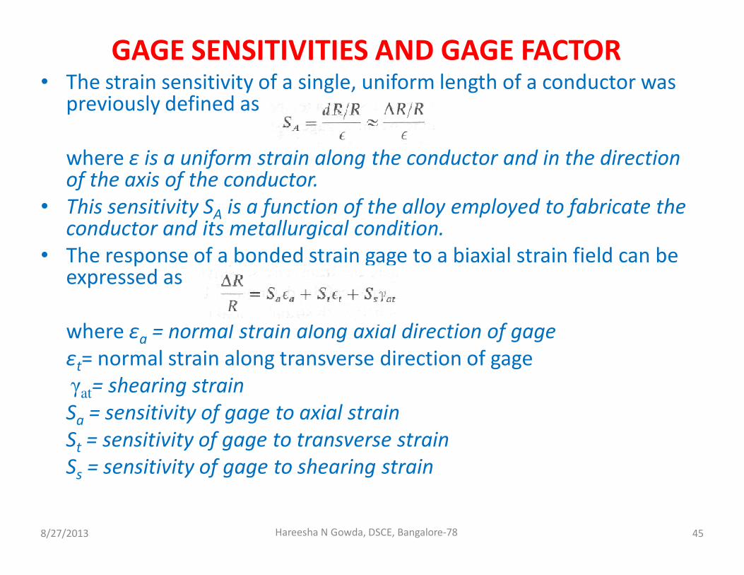
GAGE SENSITIVITIES AND GAGE FACTOR• The strain sensitivity of a single, uniform length of a conductor was
previously defined as
where ε is a uniform strain along the conductor and in the direction of the axis of the conductor.
• This sensitivity SA is a function of the alloy employed to fabricate the conductor and its metallurgical condition.
• The response of a bonded strain gage to a biaxial strain field can be expressed as
where εa = normal strain along axial direction of gage
εt= normal strain along transverse direction of gage
γat
= shearing strain
Sa = sensitivity of gage to axial strain
St = sensitivity of gage to transverse strain
Ss = sensitivity of gage to shearing strain
8/27/2013 45Hareesha N Gowda, DSCE, Bangalore-78
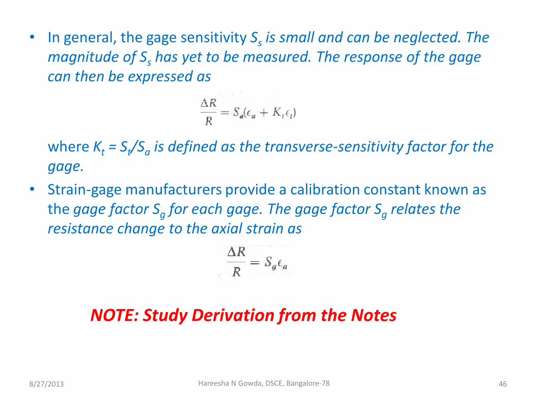
• In general, the gage sensitivity Ss is small and can be neglected. The
magnitude of Ss has yet to be measured. The response of the gage
can then be expressed as
where Kt = St/Sa is defined as the transverse-sensitivity factor for the
gage.
• Strain-gage manufacturers provide a calibration constant known as
the gage factor Sg for each gage. The gage factor Sg relates the
resistance change to the axial strain as
8/27/2013 46Hareesha N Gowda, DSCE, Bangalore-78
NOTE: Study Derivation from the Notes

ENVIRONMENTAL EFFECTS
• The performance of resistance strain gages is markedly
affected by the environmental factors such as
– Moisture and Humidity
– hydrostatic pressure
– nuclear radiation
– temperature extremes
– Cryogenic temperature
– Strain cycling
8/27/2013 47Hareesha N Gowda, DSCE, Bangalore-78

1) Effects of Moisture and Humidity
• A strain-gage installation can be detrimentally affected by direct
contact with water or by the water vapor normally present in the air.
• The water is absorbed by both the resistance and carrier and gage
performance is affected in several ways.
• Moisture decreases the gage-to-ground resistance.
• The water also degrades the strength and rigidity of the bond and
reduces the effectiveness of the adhesive in transmitting the strain
from the specimen to the gage.
• Plastics also expand when they absorb water and contract when
they release it; thus, any change in the moisture concentration in
the adhesive will produce strains in the adhesive, which will in turn
be transmuted to the strain moisture-induced adhesive strains will
produce a strain-gage response that cannot be separated from the
response due to the applied mechanical strain.
8/27/2013 48Hareesha N Gowda, DSCE, Bangalore-78

1) Effects of Moisture and Humidity
• Finally, the presence of water in the adhesive will cause electrolysis
when current pass through the gage.
• During the electrolysis process, the gage filament will erode and a
significant increase in resistance will occur.
• Again, the strain gage will indicate a tensile strain due to this
electrolysis which cannot be differentiated from the applied
mechanical strain.
8/27/2013 49Hareesha N Gowda, DSCE, Bangalore-78

2) Effects of Hydrostatic Pressure
• In the stress analysis of pressure vessels and piping systems, strain
gages are frequently employed on interior surfaces where they are
exposed to a gas or fluid pressure which acts directly on the sensing
element of the gage.
• Under such conditions, pressure-induced resistance changes occur
which must be accounted for in the analysis of the strain-gage data.
8/27/2013 50Hareesha N Gowda, DSCE, Bangalore-78

2) Effects of Hydrostatic Pressure
• The hydrostatic pressure p produces a strain in the specimen which
is given as
where KT = —(1 - 2v)/E is often referred to as the compressibility
constant for a material.
8/27/2013 51Hareesha N Gowda, DSCE, Bangalore-78

4) Effects of Nuclear Radiation
• Several difficult problems are encountered when
electrical-resistance strain gages are employed in nuclear-
radiation fields.
• The most serious difficulty involves the change in electrical
resistivity of the strain gage and lead wires as a result of
the fast-neutron dose.
• This effect is significant; changes of 2 to 3 percent in ΔR/R
have been observed with a neutron dose of 1018 nvt.
• These changes in resistivity produce zero drift with time
which can be as large as an apparent strain of 10,000 to
15,000με.
Note: nvt = neutrons/cm2
8/27/2013 52Hareesha N Gowda, DSCE, Bangalore-78

4) Effects of Nuclear Radiation
• The exact rate of change of resistivity is a function of the
strain-gage and lead-wire materials, the state of strain in
the gage, and the temperature. Typical changes in
resistance with integrated fast-neutron flux are shown in
Fig.
8/27/2013 53Hareesha N Gowda, DSCE, Bangalore-78

5) Effects of High Temperature
• Resistance-type strain gages can be employed at elevated
temperatures for both static and dynamic stress analyses; however,
the measurements require many special precautions which depend
primarily on the temperature and the time of observation.
• At elevated temperatures, the resistance R of a strain gage must be
considered to be a function of temperature T and time t in addition
to strain ε.
• Equation can then be expressed in terms of the three sensitivity
factors as
8/27/2013 54Hareesha N Gowda, DSCE, Bangalore-78

6) Effects of Strain Cycling
• Strain gages are frequently mounted on components subjected to
fatigue or cyclic loading, and the life of the component during which
the gage must be monitored can exceed several million cycles.
• Three factors which must be considered in a fatigue application are
zero shift, change in gage factor, and failure of the gage in fatigue.
• As the strain gage is subjected to repeated cyclic strain, the gage
grid work-hardens and its specific resistance changes.
• The specific resistance change produces a zero shift.
• The amount of the zero shift depends on the magnitude of the
strain, the number of cycles, the grid alloy, the original state of cold
work of the grid alloy, and the type of carrier employed in the gage
construction.
8/27/2013 55Hareesha N Gowda, DSCE, Bangalore-78

Refer the following topics from class notes
• Strain gage circuits
– Potentiometer circuits
– Wheatstone bridge circuits
– Constant current circuits
• Constant current potentiometer circuit
– Double constant current potentiometer circuit
– Constant current Wheatstone bridge circuit
8/27/2013 56Hareesha N Gowda, DSCE, Bangalore-78