Space Flight Requirements for Fiber Optic Components ... · Space Flight Requirements for Fiber...
15
1 Source of Acquisition 1 NASA Goddard Space Flight Center Space Flight Requirements for Fiber Optic Components; Qualification Testing and Lessons Learned Melanie N. Ott*”, Xiaodan Linda Jinb, Richard Chuska‘, Patricia Friedberg”,Mary Malenabb, Adam Matuszeski aNASAGoddard Space Flight Center, Code 562, Greenbelt Maryland 20771 bQSS Group Inc. 4500 Forbes Boulevard, Lanham Maryland 20706 %I, 7404 Executive Place, Seabrook, Maryland, 20706 dNASAGoddard Space Flight Center, Code 544, Greenbelt Maryland 20771 ABSTRACT “Qualification” of fiber optic components holds a very different meaning than it did ten years ago. In the past, qualificationmeant extensive prolonged testing and screening that led to a programmaticmethod of reliability assurance. For space flight programs today, the combination of using higher performance commercial technology, with shorter development schedules and tighter mission budgets makes long term testing and reliability characterization unfeasible. In many cases space flight missions will be using technology within years of its development and an example of this is fiber laser technology. Although the technology itself is not a new product the components that comprise a fiber laser system change frequently as processes and packaging changes occur. Once a process or the materials for manufacturing a component change, even the data that existed on its predecessor can no longer provide assurance on the newer version. In order to assure reliability during a space flight mission, the component engineer must understand the requirements of the space flight environment as well as the physics of failure of the components themselves. This can be incorporated into an efficient and effective testing plan that “qualifies” a component to specific criteria defined by the program given the mission requirements and the’componentSitations. This requires interaction at the very initial stages of design between the system design engineer, mechanical engineer, subsystem engineer and the component hardware engineer. Although this is the desired interaction what typically occurs is that the subsystem engineer asks the components or deveIopment engineers to meet difficult requirements without knowledge of the current industry situation or the lack of qualification data. This is then passed on to the vendor who can provide little help with such a harsh set of requirements due to high cost of testing for space flight environments. This presentation is designed to guide the engineers of design, development and components, and vendors of commercial components with how to make an efficient and effective qualification test plan with some basic generic information about many space flight requirements. Issues related to the ~ physics of failure, acceptance criteria and lessons learned will also be discussed to assist with understanding how to approach a space flight mission in an ever changing commercial photonics industry. Keywords: components, environmental, space, flight, qualification, photonic, fiber, optic, radiation 1. INTRODUCTION In order to construct a reliable space flight system to meet program specifications,a design engineer must first consider the performance requirements for the system as requested by the program. This means that the project system engineer must supply a list of performance specifications for the system. Although the system requirements change to some degree as the design engineer discovers the limits on the performance possible. The negotiation between design, development, system and spacecraft engineers continues until a balance is reached. The performance is achieved with what the development and design engineers can formulate from available components. ’ The design engineer will then build a system to meet these requirements as a concept demonstration in a “bench” type form or prototype. Let us assume that this prototype is constructed with commercial fiber components where available and bulk components where fiber components are not available on this prototype. To take this system to the next phase, a development engineer with the design engineer will need to formulate a plan for making the prototype into a rugged system that can withstand the environmental specifications of the program. This is usually a great challenge since in order to meet state of the art * [email protected], 301-286-0127, URL: http://misspiggy.gsfc.nasa.gov/photonics https://ntrs.nasa.gov/search.jsp?R=20070016616 2020-06-04T23:52:25+00:00Z
Transcript of Space Flight Requirements for Fiber Optic Components ... · Space Flight Requirements for Fiber...

1 Source of Acquisition 1 NASA Goddard Space Flight Center
Space Flight Requirements for Fiber Optic Components; Qualification Testing and Lessons Learned
Melanie N. Ott*”, Xiaodan Linda Jinb, Richard Chuska‘, Patricia Friedberg”, Mary Malenabb, Adam Matuszeski
aNASA Goddard Space Flight Center, Code 562, Greenbelt Maryland 20771 bQSS Group Inc. 4500 Forbes Boulevard, Lanham Maryland 20706
%I, 7404 Executive Place, Seabrook, Maryland, 20706 dNASA Goddard Space Flight Center, Code 544, Greenbelt Maryland 20771
ABSTRACT
“Qualification” of fiber optic components holds a very different meaning than it did ten years ago. In the past, qualification meant extensive prolonged testing and screening that led to a programmatic method of reliability assurance. For space flight programs today, the combination of using higher performance commercial technology, with shorter development schedules and tighter mission budgets makes long term testing and reliability characterization unfeasible. In many cases space flight missions will be using technology within years of its development and an example of this is fiber laser technology. Although the technology itself is not a new product the components that comprise a fiber laser system change frequently as processes and packaging changes occur. Once a process or the materials for manufacturing a component change, even the data that existed on its predecessor can no longer provide assurance on the newer version. In order to assure reliability during a space flight mission, the component engineer must understand the requirements of the space flight environment as well as the physics of failure of the components themselves. This can be incorporated into an efficient and effective testing plan that “qualifies” a component to specific criteria defined by the program given the mission requirements and the’component Sitations. This requires interaction at the very initial stages of design between the system design engineer, mechanical engineer, subsystem engineer and the component hardware engineer. Although this is the desired interaction what typically occurs is that the subsystem engineer asks the components or deveIopment engineers to meet difficult requirements without knowledge of the current industry situation or the lack of qualification data. This is then passed on to the vendor who can provide little help with such a harsh set of requirements due to high cost of testing for space flight environments. This presentation is designed to guide the engineers of design, development and components, and vendors of commercial components with how to make an efficient and effective qualification test plan with some basic generic information about many space flight requirements. Issues related to the
~ physics of failure, acceptance criteria and lessons learned will also be discussed to assist with understanding how to approach a space flight mission in an ever changing commercial photonics industry.
Keywords: components, environmental, space, flight, qualification, photonic, fiber, optic, radiation
1. INTRODUCTION
In order to construct a reliable space flight system to meet program specifications, a design engineer must first consider the performance requirements for the system as requested by the program. This means that the project system engineer must supply a list of performance specifications for the system. Although the system requirements change to some degree as the design engineer discovers the limits on the performance possible. The negotiation between design, development, system and spacecraft engineers continues until a balance is reached. The performance is achieved with what the development and design engineers can formulate from available components. ’ The design engineer will then build a system to meet these requirements as a concept demonstration in a “bench” type form or prototype. Let us assume that this prototype is constructed with commercial fiber components where available and bulk components where fiber components are not available on this prototype. To take this system to the next phase, a development engineer with the design engineer will need to formulate a plan for making the prototype into a rugged system that can withstand the environmental specifications of the program. This is usually a great challenge since in order to meet state of the art
* [email protected], 301-286-0127, URL: http://misspiggy.gsfc.nasa.gov/photonics
https://ntrs.nasa.gov/search.jsp?R=20070016616 2020-06-04T23:52:25+00:00Z
b
performance requirements for a system, component choices are many times in conflict with what is considered “reliable”. If the space craft system requirements are harsh, as in environmentally, it can make the development process a challenging task. Couple that dilemma with the fact that some components are no longer readily available as they once were during the telecommunications market surge and now the engineer is faced with few options for component selection. Such is the case many of us are facing when designing state-of-the-art systems to for space and other harsh environments. In order to meet this challenge, the development and the design engineer need the assistance of a component engineer who is knowledgeable on the subject of application, reliability and testing of commercial components for harsh environments. Sure, years ago it was easier because when on program used a component and qualified it for space, the next program could use it as well and claim its “heritage”. The current state of the market disallows for “heritage” as it once had since any changes to a component manufacturing process therefore, changes the part and negates its ?heritage” to some degree. The component engineer, based on a changing market, has to be aware of the materials and processes used for fabrication of these components as well as the physics of failure on a variety of materials and components. By incorporation of this knowledge into the final hardware, the program now has a chance of providing a highly reliable system for a harsh environment based on commercial components. NASA Goddard Space Flight Center components engineers call this approach ‘Technology Validation Assurance”, where research on materials and packaging and knowledge based testing can mitigate the risk of environmental related failures under harsh environmental conditions.
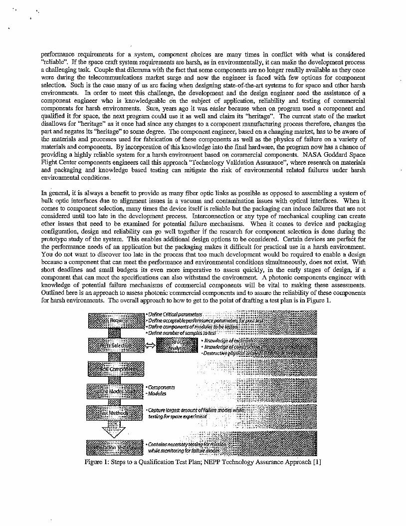
In general, it is always a benefit to provide as many fiber optic links as possible as opposed to assembling a system of bulk optic interfaces due to alignment issues in a vacuum and contamination issues with optical interfaces. When it comes to component selection, many times the device itself is reliable but the packaging can induce failures that are not considered until too late in the development process. Interconnection or any type of mechanical coupling can create other issues that need to be examined for potential failure mechanisms. When it comes to device and packaging configuration, design and reliability can go well together if the research for component selection is done during the prototype study of the system. This enables additional design options to be considered. Certain devices are perfedt for the performance needs of an application but the packaging makes it dificult for practical use in a harsh environment. You do not want to discover too late in the process that too much development would be required to enable a design because a component that can meet the performance and environmental conditions simultaneously, does not exist. With short deadlines and small budgets its even more imperative to assess quickly, in the early stages of design, if a component that can meet the specifications can also withstand the environment. A photonic components engineer with knowledge of potential failure mechanisms of commercial components will be vital to making these assessments. Outlined here is an approach to assess photonic commercial components and to assure the reliability of these components for harsh environments. The overall approach to how to get to the point of drafting a test plan is in Figure 1.
Figure 1 : Steps to a Qualification Test Plan; NJ3PP Technology Assurance Approach [ 11

In 2005 Suzzanne Falvey of Northmp Orumman drafted this flowchart after reviewing the approach outlined in a presentation given by M .Ott during the Advanced Microelectronics and Photonics for Satellites Conference.[ 11 This is a graphical representation of the approach discussed here where the key item to any well planned qualification schedule will be based on a thorough knowledge of the components failure modes. For programs that want to include more than one vendor per component, increased confidence of the reliability f6r longer duration mission and have the funding to extend the program a prescreening qualification should also be considered to insure higher reliability. In cases where the application of a particular component is challenging or vastly different from past implementations, prescreening could also be justified as a feasibility study but not for quantitative results. In most cases, budgets are tight and schedules are short and for these cases a quality-like test is conducted as a prescreening.
Once the performance requirements are supplied, the critical parameters for each component in the system can be established. Some parameters are less sensitive to environmental conditions than others. Therefore, once the critical parameters are established per component, then the deviation of those parameters will need to be addressed. For example, how much can you allow your sensor output wavelength to shift as a result of thermal changes during the mission and still provide the information necessary? Then the environmental requirements are established that allow you to compare what you have chosen as a reasonable tolerance for your critical parameters against environmental induced changes. The major environmental issues are: contamination or non metallic materials issues associated with vacuum exposure and operation, launch vibration, thermal changes as a result of orbit parameters, and radiation exposure. Also from knowledge of the failure modes or physics of failure on each of the components themselves some critical tests can be fonnulated to bring out a majority of the failure modes. Incorporating, the environmental testing necessary with innovative test methods that bring out the known failure modes, a qualification or characterization plan for each commercial component can be formulated. Will this mitigate all risk against failure? No, but it’s a reasonable start at providing knowledge based assessments and providing the most reliable system possible given the situation of COTS usage. Even in cases of components that are part of the military qualification process, failures still occur. So completely eliminating the possibility of failures is unlikely but the probability can be greatly reduced.
An_other reason for being well educated about the physics of failure is because vendors can not afford to pay the bill to go through extensive testing as they once did for the military for compliance to the military specifications. There is no incentive for a vendor to use precious resources to extensively test their commercial components to a set of unusually harsh environmental parameters when the customer is only going to purchase a few on a one time, one-of-a-kind instrument. The expectation that a vendor is obligated to meet a large amount of difficult demands for a space flight customer for the purpose of stating that this partnership exists, its not beneficial to the vendor in producing the business it would take to justify the costly expenditure. It is important that even the component engineers understand that to achieve high reliability that they themselves need to be responsible for making that happen between analysis and testing. Most commercial processes can not be changed to accommodate a space flight build of a particular component, therefore the analysis especially with regards to processes and construction can lead to suggestions to the vendor however, do not expect that if the process change involves extra money spent on the part of the vendor its not likely going to be feasible and if it is it will no doubt result in a very costly non-recurring engineering fee that the space flight program will need to fund. The old saying “you can get a cheap job done but it won’t be good or you can get a good job done but it won’t be cheap” needs to be considered when approaching the commercial industry about using commercial parts in space. Many vendors are even going away from compliance with the Telecordia certifications since the majority of their customers today are not commercial telecommunications providers but are industrial customers using light for manufacturing of their products. Even if a part was originally part of the telecommunications components base 7 years ago, you may be surprised to find that the same exact part being produced today is no longer being tested to Telecordia standards even if was in the past. [2]
2. COMPONENT QUALIFICATION PLAN
2.1 Introduction Since there are typically no space-qualified components for systems available, an approach to parts qualification of commercial-off-the-shelf for space environments is required. To insure the greatest risk mitigation, the parts selected for the instrument should be qualified by lot or batch. A “lot” is defined as a group or batch of parts that are manufactured in a short period of time with respect to each other and with the same materials. The final flight implementation is

manufactured with parts from this qualified lot. A small sample from the lot is put through full qualification testing based on the construction of the component found through materials and construction analysis. The qualification method usually consists of; construction analysis and screening of any materials that are found to be noncompliant, vibration testing, thermal andor thermal vacuum testing, and radiation testing. This is the common COTS approach used at NASA as prescribed by the NASA Parts and Packaging Program. [2,3] Figure 2 illustrates the order of testing to be performed during a COTS qualification, the details of which are described after.
Use components !evels OT d
* Thermal-vacuum when necessary *
Figure 2: COTS Space Flight Qualification Plan Approach [ 11
2.2 Materials and Construction Analysis: ‘When making a component selection or working with a manufacturer to supply a specialized component, it is not often possible to specifjr manufacturing processes and materials. NASA utilizes small numbers of very specialized components and this makes it non economical for commercial vendors to provide a product that can not be sold in large quantity. However, it is often possible to affect small changes duriiig manufacturing that can greatly affect the overall space flight reliability of a commercial component. Materials identification is the first step in the process of affecting the reliability of a commercial part in a space flight environment. If information can not be shared from vendor to user, a destructive physical analysis (DPA) can be performed in which all materials can be identified as well as the location of the material in the package. In this way, an analysis can provide reliability information of the packaging configuration as well as provide information about which materials are non-metallic for contamination related concerns. ’
In all cases, where the materials are identified by the vendor or if identified by another method, the non metallic materials should always be characterized for their outgassing properties in a vacuum environment. Even if the rest of the system would not be effected by stray materials outgassing and then redepositing on surfaces, other systems nearby may be contaminated. The project lead contamination expert should supply information regarding system contamination sensitivity to outgassing materials.
For characterization of materials NASA typically uses the ASTM-E595 procedure for thermal vacuum exposure and analysis of materials.[4] This test method is entitled “Standard Test Method for Total Mass Loss and Collected Volatile Condensable Materials from Outgassing in a Vacuum Environment“. This method is used as a screening test for materials that could provide a contamination issue as a result of large volatile content, which can include trapped solvents, un-reacted materials and water. The test is conducted at 125°C usually for 24 hours at less than Torr. The ciiteria for this test are for the Total Mass Loss (TML) to be less than 1 .O% and the Total Collected Volatile Condensable Materials (CVCM) to be less than 0.1%. This screening test does not provide definitive information about contamination

but as an initial screening can provide the contamination engineer enough information to assess whether or not to prohibit certain materials, require preprocessing of materials, or to require additional measures to guard against the potential threat of contamination. Knowing that contamination is such a large failure mode of high power laser systems, this issue is extremely important to space flight laser development engineers.
In cases where a material TlML is higher than the screening criteria but the CVCM is very low and less than the screening criteria it can still be usable depending on the levels of contamination allowable. The Epotek 353ND epoxy is a good example of this where even using a very high temperature cure schedule, the TML is still above the acceptance criteria but the CVCM is well enough below. Having a low CVCM indicates that the material is less likely to deposit on nearby optics once released. In cases where materials do not pass ASTM E595 such as with the material Hytrel, a “preconditioning” vacuum exposure procedure can be conducted, where upon completion of this procedure, the material will then pass the ASTM-E595 test. When all else fails and the system has been assembled with outgassing materials regardless of every effort to avoid it, post manufacturing decontamination can be used to drive off any volatile materials. This is especially necessary in the case where the fabricated hardware will be placed nearby to other optics such as mirrors and bulk telescope optics. Since this test is costly and requires a much larger vacuum chamber to accomplish, performing this type of decontamination would be considered more of “last resort” option and not a recommended regular practice. It is however a common practice to perform this level of decontamination at the box or instrument level to better alleviate the possibility of contamination as a result of vacuum exposure once already in flight. It is important to note that most acrylate coated fiber do in fact outgas but when used in configuration is acceptable for space flight use when tested in configuration to a modified version of ASTM-E595.
Materials analysis can also uncover potential long term reliability issues such as packaging induced failures. During the GLAS mission it was found that indium solder was used too close in proximity to the tiny gold wires in the packaging configuration.[5,6] Due to indium creep, the wires became an intermetallic and disintegrated as a result of being driven at high currents for long pulse duration. Destructive physical analysis of this packaging design showed that many of the wires were in various stages of becoming an intermetallic from “indium attack” of the gold. This allowed designers to suggest changes to the packaging configuration to avoid this reliability hazard for future missions. This is one example of how upfront materials analysis on commercial components can be very instrumental in avoidance of packaging related failure modes. In all cases, it should be the first step performed when checking for potential problems with flying commercial components.
2.3 Vibration Testing Parameters Random vibration is used as a qualification and screening test at the component level. This is also required at the system level by all programs in addition to sine sweep. Shock testing is typically not conducted unless the shock values are abnormally high as compared to typical space flight shock values or are specified for qualification testing at the component level per the “General Environmental Verification Specification (GEVS) for STS and ELV Payloads, Subsystems and Components”[7]. Random vibration testing is conducted at twice the levels from the proto-flight system level as defined by the launch vehicle. The system level requirements are generated for the instrument itself and typically these instruments are flown once they have endured vibration testing, this is known as “protoflight”. With funding inadequate to fully qualify any system and tight schedule demands, the protoflight is more often the case. Although components that are tested for random vibration are a subset of what usually gets put into the space flight instrument, they are typically not flown once they have endured qualification. That only occurs at the insbxment level. The parameters of the random vibration test are generated based on the vibration conditions expected as a result of the launch vehicle. NASA’s space flight vibration parameters are usually much less stringent than those for the Military. A typical profile for testing at the box or instrument level usually totals no more than 10 to 14.1 gmx. For component testing, the profile parameters are doubled and the overall vibration (acceleration) level totals 14.1 grms (atleast, and typically more) as a result of mathematical integration of the acceleration parameters over the entire spectral frequency range. The spectral frequency range for space flight is usually between 20 and 2000 Hz. The random vibration test is typically conducted for 3 minutes for each axis of orientation. The following profile is published in the General Environmental Verification Specification for STS and ELV Payloads, Subsystems and Components for payloads of 50 pounds or less.[7] This is what would be expected at the box or instrument level for protoflight. Here is an example of how the system requirements flow to the component requirements.

Table 1: GEVS Protoflight Generalized Vibration Levels for Random Vibration Testing. I Frequency-) I Acceleration Spectral Density Levels
+6 dB/octave
800-2000 -6 dB/octave
Overall
50-800
The rule of thumb in cases where the “qualification” is on very few samples or engineering models, is to use the profile of Table 1 with the acceleration spectral density levels doubled at the ends of the range. Table 2 shows the profile that would be used for qualification of a small commercial part or component.
Table 2 : Random Vibration Levels for Small Parts and Components Based on GEVS Instrument Protoflight Levels. I frequency-) I Acceleration Spectral Density 1
Levels .os2 IEz
+6 dB/octave
800-2000 -6 dB/octave
Overall
~1 50-800
.os2 IEz
Using the levels outlined in Table 2 commercial components can be tested at the part level to ensure reliability after space flight launch. It is also the case that vibration testing can bring out known failure modes especially associated with packaging. Again, this profile is used when testing for 3 minutes in each axis of orientation. Functional performance testing should be conducted to ensure the part still meets performance requirements with a margin assigned to the acceptance criteria. Where possible in-situ testing is used especially for testing of assembly interconnecting devices. This would be significant if the system is expected to be operational during launch or re-entry.
2.4 Thermal Testing Parameters For thermal requirements there is no strict “standard” because each project will establish a thermal environment for operation and for survival at the system or instrument level. Here again, the performance specification for each component during thermal variations established at the system level will need to be established prior to testing for identification of the acceptance criteria for “qualification”. It is crucial to understand the limitations of the component of interest (under test) such that the parameters of the test are set based on system constraints (how hard it would be to adjust the system thermal limits on your subsystem) or on the limitations of the component itself. Many commercial parts are limited to the basic standard of -25°C to +85”C (which could be acceptable for GEO and LEO orbits) and others that ’are Telecordia certified or qualified are rated for -45°C to +85”C for storage and operational between -40°C to +85”C. The project will specify the operational and survival thermal range based on the expectations of orbit and orientation with respect to the sun, from there the component levels for testing should be set at 10 degrees above and below each extreme of the thermal range. If the instrument operational requirement is 0°C to +50”C (which is considered benign as compared to some missions that require -200°C to +lOO”C) than the component testing range should be set for -10°C to +60”C and should be monitored in-situ during testing. Telecordia standards require 2000 hours minimum for accelerated aging testing. For long term reliability information it is always best to choose a Telecordia certified component that has been tested over long duration. Then as a user, and depending on the part type, perform 100 to 60 cycles to provide enough information during qualification to either bring out known failure modes or assure that the part will survive the mission as procured. In some cases it may not be enough to perform the materials analysis and thermal cycling alone. If an adequate materials analysis could not be performed or if the component has a known degradation, instability or failure in a vacuum environment such as non hermetic modulators, than although the thermal testing can help with stressing the part for aging information, a thermal-vacuum test would also be necessary.
2.5 Thermal Vacuum Testing Most passive optical components show failure modes if they are going to occur in a vacuum environment within the
first 20 cycles of thermal vacuum exposure with longer term reliability established by a minimum of 100 cycles. Where

necessary thermal vacuum testing is performed to insure that no degradation or failure modes are activated in a vacuum environment. Some degradation modes are intermittent and require insitu monitoring to assure vacuum environment reliability. The same thermal range rules apply for thermal-vacuum testing; always test 10 degrees above and below the range specified at the instrument level and cycle as much as feasible. The thennal vacuum cycling can be at minimum 20 cycles for prescreening urposes where testing to 100 cycles considered more of a qualification test. The pressure should be set to to 10- Torr or as low as possible given the limitations of the thermal vacuum chamber. The actual space vacuum is more on the order of lo-' Torr so the lower the pressure the better for vacuum testing.[13] Insitu optical performance monitoring is necessary to insure that the component does not exhibit degradation or instability only in a vacuum. In that case, the part may not function in a vacuum environment but once under ambient conditions returns to normal functionality.
B
2.6 Radiation Testing Parameters Background radiation can be specified as anywhere from 15 Krads to 100 Krads total dose for a typical mission, although the Military may specify much higher values in the Mrads. These numbers are generated based on the type of orbit, mission, shielding expected and mission years. If we focus mostly on earth orbiting type space craft, the lower earth orbit (LEO) missions can see background radiation anywhere in the range 5 to 10 Krads and most of this dose is accumulated during passes through the South Atlantic Anomaly (SAA).
Figure 4 Earth Orbiting Satellite Definitions from h t t D : / / ~ ~ w w . i n e t d n . ~ ~
The Middle Earth Orbit (MEO) path passes through the Van Allen Belts and the total dose accumulation can be anywhere from 10 to 100 Krads. For Geosynchronous orbits (GEO) the majority of the dose is accumulated from cosmic rays and is typically around 50 Krads with a travel path above the Van Allen Belts. The radiation total dose amounts here are based on typical spacecraft shielding and a 7 year mission. In some cases where the hardware is not shielded by the spacecraft, the levels even for background radiation can reach Mrads for expected total ionizing dose. Many electronic parts are tested based on total dose alone but optical fiber has other dependencies such as the dose rate, temperature during exposure, and the wavelength of operation. Laser diodes are most susceptible to displacement damage effects which are best stimulated by proton testing as opposed to gamma ray radiation exposure. To get a sense of how protons equate in total ionizing dose, the conversion fi-om protons to total dose for 60 MeV protons is 10" protons = 1 Krad total dose.

Unless particulate or heavy ion levels are exceptionally high, fiber devices are not largely susceptible to displacement damage effects as much as radiation induced color center formation resulting in a degradation of the transmission signal (radiation induced attenuation). Therefore, gamma radiation testing is comparable if not the worst-case scenario for testing fiber components to total dose levels as specified by the radiation physicist and the project.[8] For fiber devices the dopant concentration of the fiber guiding materials are the largest contributor to radiation induced darkening which is a transient effect in that once the radiation source is removed the fiber eventually recovers to nearly the original attenuation with a small residual attenuation as a result of displacement damage or permanent ionization. For optical fiber, since total dose as well as dose rate is important, viewing the details of typical missions can help give perspective about testing parameters or at least environmental parameters for extrapolation of the testing data. Table 3 summarizes the total dose, mission duration and calculated average dose rate for several GSFC missions.
Program GLAS MLA EO- 1
Total Dose Mission Length Dose Rate 100 Krads 5 years 0.04 raddmin 30 Krads 8 years 0.01 1 rads/min 15 Krads 10 years 0.04 raddmin
GLAS is the Geoscience Laser Altimeter System [9], MLA is the Mercury Laser Altimeter [lo], and EO-1 is Earth Orbiter 1. Usually the total dose is divided by the mission duration to calculate an average dose rate. However, to calculate the average dose rate for MLA, the duration of dose was changed to 5 years for the 8 year mission, as a conservative estimate of when the majority of the dose would be accumulated. Usually the radiation physicist on the project will be the one to supply the mission expected radiation environmental parameters and from there a test plan can be devised that focuses on the best known failure mode expected for that component.
2.6.1 Radiation Testing Methods A majority of optical fiber used in past missions and most susceptible to radiation, were usually multimode for communications and large core multimode for some LIDAR applications. For testing of these fibers, the two dose rate extrapolation model developed by E. Joe Friebele at NRL was used.[l 11 This model allows for two total dose tests to be performed with all parameters kept the same except for the dose rate. From the data an expression for the attenuation at any dose and total dose can be formulated. When using this model its best to stay at low dose rates as compared to the actual expected dose rate. For example we typically test less than 100 raddmin to collect data for GSFC missions. The other parameters that are key to producing a conservative result are temperature and wavelength. If the operation wavelength for the instrument can not be used during testing for monitoring of the fibers under test, than its best to use a shorter wavelength as close as possible to the operational wavelength. This is because fiber is typically more sensitive at shorter wavelengths therefore providing a more conservative data set. When using a source to monitor the optical fiber during testing, a total average power of less than 1 microwatt will keep the photobleaching effects from correcting the radiation induced darkening. For temperature, its best to know the thermal environment very well. If there is denoted a period of time when the temperature will remain cold, or a temperature range is given for operation without details as to how long at cold temperatures the instrument will remain, the rule of thumb is to use the coldest operation temperature for testing. In summary the idea is to provide the parameters for testing that are representative of the harshest conditions for the optical fiber; dark cold and of short wavelength. For further study reference [8] provides a summary of optical fiber radiation data. This study reference allows the engineer to make comparisons among a variety of types and vendors.
3. LESSONS LEARNED: TERMINATIONS
3.1 Optical Fiber Assembly Manufacturing Processes When building optical fiber assemblies many engineers, accept that if the components are qualified for space than the assembly is qualified for space. Unfortunately one does not equal the other. When choosing a vendor or contractor to fabricate the assemblies be sure to validate the termination process used, not just the parts used. Even if the components have passed vibration, thermal and radiation testing during a past program, its important to identify when the qualification test was a test of the components and their compatibility and when the test was a validation of the termination process of the manufacturer or assembler. Some vendors use a post manufacturing thermal test to weed out the infant moralities. Using ten thermal cycles to screen for any abnormalities or potential failures as a result of

improperly performed processes may provide for an adequate screening to insure the process is performed correctly on a day to day basis. However, the first time you elect to use a commercial vendor, a validation of the termination process itself should be performed. This would involve at minimum a vibration and thermal qualification test. Radiation is essentially a test of the cable materials and is not going to provide any information about the termination processes used. Beyond this, a few lessons learned about manufacturing processes that have recently been studied at GSFC will be shared here.
3.1.1 Epoxy and Stresses When making choices for a space flight assemblies, manufacturers are asked to consult the outgassing database hosted at NASA Goddard Space Flight Center.[4] The data presented shows the results of testing each material to the ASTM- E595 procedure. For epoxies it also lists the curing schedule used for the various materials under test to ASTM-E595. The logical conclusion when deriving a procedure from the available data is to choose the cure schedule that bests matches the passing criteria for the ASTM-E595 where the TML and the CVCM are under the necessary limits as mentioned in section 2.2 on materials analysis. For example an Epotek epoxy may pass the screening criteria but at a 200°C cure schedule. So a termination engineer may see this cure schedule as the way to insure that the epoxy used to bond the optical fiber to the termini or connector ferrule will not outgas. If the assembly being built is going to be used at a lower temperature this creates a situation where the coefficient of thermal expansion (CTE) can be activated by a large change in temperature which in turn will exert a stressful condition on the fiber. Even if cracks don't appear at the time of the first round of thermal testing they can in fact appear later. Germanium doped graded ihdex fiber will exhibit this quicker than other types of optical fiber. Germanium doped graded index multimode fiber is known for its brittleness by design of the dopants used. The graded index multimode represents one of the worst cases when identifying multimode constructions that are prone to cracking. Even when viewed through a microscope the cracks that exist are not visible. But as a result of the dopant concentration internal stresses exist just by design. The graded index fiber possesses a larger amount of dopant concentration in the center of the core which falls off slowly as one travels out in the radial direction. This sets up an internal stress condition where the CTE of the germanium doped silica at the center is higher than that of the surrounding material and the silica cladding. Micro-cracks can easily originate from this center because of the internal stresses inherent to the fiber structure. Another source of micro-cracking is based on the atomic structure of the dopant and the silica that mismatch in size as well as contaminates that enter the material during processing. So curing at a high temperature can set up a situation where the fiber will crack during thermal extremes. The result is destructive stress induced by a combination of constrained CTE (epoxy is surrounded by rigid geometry such as a fiber ferrule and the fiber itself) and a large temperature excursion which activates the CTE. A slight defect can be grown into a larger crack across an end face from the stress inflicted and can further propagate from water in the environment getting into the crack well before the flight hardware is ever launched. A good example of this is in the figure below.
Figure 5: Bright field image at 200X, Dark field image at 200X
Besides the contamination seen in Figure 5, there is also a crack t3nt originated from a center position in the core and was exacerbated by the stresses exerted from its surroundings. A crack that was propagated by thermal stresses could appear as the endface in Figure 5 and could occur as a result of a high temperature cure when used at cold temperatures. Using too much epoxy (more than a few microns) in a constrained situation such as a fiber and fiber ferrule will exacerbate potential micro cracks as well. Which is why most vendors understand that limiting the amount of epoxy is essential for the bond between connector ferrule and fiber. This also points out the need for qualification of a termination process and the assembly itself as opposed to only qualifying the parts that are used to build the assembly. This cracking

that can result in considerable signal transmission loss in the short term lifetime of the assembly, was caused by improper termination processes. In cases where large amounts of epoxy are required for bonding purposes, a well distributed fine diamond dust at .05 microns or less can be used for rigid loading and will quench the CTE therefore limiting the stresses on the fiber itself.
3.1.2 Polishing processes Most optical fiber assembly manufacturers know that grinding during the polishing process with too high of a grit will cause latent defects later that show up as cracks that were temporarily masked during final inspection. Polishing and grinding are two very different processes but both are involved in preparing an optical fiber end face. .Essentially grinding actually cracks the surface of the glass with material particles that are harder than the glass. Polishing is more of a “molecular phenomenon caused by adhesive forces between the molecules of the polishing agent and those of the surface”[l2] . Because of this it is imperative that before the final polishing commences, all scratches and cracks from higher grit grinding processes be thoroughly removed by finer grit lapping film. If this doesn’t occur than a surface that appeared “polished” just after termination may show propagation of any underlying micro-cracks later, left over from a grinding process that preceded it with too high of a grit. At NASA GSFC we use nothing larger than 5 micron lapping film to “polish” (in termination jargon) away excess fiber and epoxy because it will remove excess material without creating large scratches that are too large to removed by the following lapping processes.
3.1.3 Inspection and Cleaning During final inspection of a connector or termini end face, NASA GSFC uses a 200X image to insert into the quality assurance documentation for certification of the termination. We also use back-lighting and dark field images to especially search for cracking that may be too slim in gap to be detected without changing the lighting geometry. Light will propagate through a crack that is less than 1/8 of a wavelength of light.
In the images of Figure 6, the crack doesn’t show up in the bright field images but does in the dark field images. This illustrates how good microscopy methods are necessary to provide good quality assurance.
~
Another practice imperative to assuring the long term reliability of all integrated assemblies is to clean termini ends and inspect prior to ever mating two termini or connectors together. If contamination exists on one of the termini the impact stress can increase the likelihood of any micro cracking already inherent to the core of the fiber to propagate into a large and visible crack that will meatlv effect transmission loss.
In Figure 7 the photos illustrate what occurs as a result of contamination caught between two optical fiber interfaces when mated into a connector. The termini end face was a convex geometry (domed outward). This made the situation of having contamination between the surfaces that much likely to damage the end face by impact stress. Also noted were

the features at the center of the crack and those features were investigated further. Figure 8 shows the results of Scanning Electron Microscopy performed on that center region
Figure 8: 4.86KX SEM image, and 12.1KX SEM image of area of contamination.
The images and subsequent Energy Dispersive Spectroscopy performed showed that the area of contamination included sodium, chlorine, and potassium and this indicates human contact. Normally fiber made of pure silica is resistive to corrosion but when doped with germanium as with typical graded index fiber, the resistance is considerably decreased. Thus making the case that it is imperative for operators during integration to clean and inspect all fiber termini prior to mating and to avoid physical contact with the end face itself. To do otherwise is to set the stage for severe signal degradation or failure of the link entirely.
4.1 Introduction Some space flight missions break new ground where technology is concerned because of the non negotiable space craft requirements. The Lunar Reconnaissance Orbiter (LRO) is an example of this for the fiber optics aboard used as part of the receiver optics for laser ranging applications. A receiver box will be placed at the end of an antenna that is deployed once the space craft reaches orbit. Because it will be necessary to steer the antenna towards its target it also includes gimbals that enable full x and y motion control. The receiver box includes a fiber bundle that will transmit the signal received to the instrument in which it will be processed. This requirement means that optical fiber will be wrapped around several gimbals and in constant motion for the duration of the mission. The temperatures are expected to cycle but the worst case for fiber during motion will be at cold temperatures. Fiber will be more brittle and experience higher losses at cold temperatures. This aspect of the design represents a high risk item since no data exists that assures that losses will not be too high and that the fiber will not be cracked by the motion of the gimbals during cold thermal exposure.- In this case it is necessary to conduct a prescreening qualification test to insure the feasibility of the implementation. A prequalification test should be designed to gather as much information as possible during environmental exposure using the least means of doing so without compromising the data of greatest interest. This requires priorities to be weighed against the budget and schedule constraints. Tests such as this are only for the purpose of providing insight into the reliability and can not always provide quantitative results.
4. PRE-QUALIFICATION
4.2 Pre-qualification Experiment In order to assure that the optical fiber would survive and function adequately during cold thermal exposure during gimbaled motion, an experimental setup was constructed to prescreen the fiber under these constraints.
Figure 9: Inside view of routing of RF cable in gimbal, Inside view of FLEX-LITE" fiber cable in side gimbal cable wrap.

Figure 9 shows pictures of the inside of the cable wraps used in the gimbals that have been used in past space flight missions for testing purposes such as the Tropical W a l l Measuring Mission (TEWM) but without fiber optic cable in the cable wraps. The first picture shows a cable wrap with an RF coaxial cable and the second picture shows the same gimbal with the RF cable replaced with a single strand of J?LEX-LITEm cable made by W.L. Gore containing Polymicro Technologies FIA300330500 optical fiber.
Figure 10: Picture of gimbal system in thermal chamber with cables routed through the feed through at the chamber wall.
The 4 meter single fiber strand was wrapped into two cable wraps that are stacked together as part of the gimbal configuration and routed outside of a thermal chamber. The cable was connected to source and detector reference cables with the Diamond AVIM connectors and monitored at 850 nm for relative insertion loss during gimbal motion. Three tests were conducted at O"C, - 10°C and -20°C while moving the gimbal 180 degrees in one dimension.
+Optical Insertion Loss
Gimbal Positions Gimbal Positions and Optical Insertion Loss
From 5590 to 5596 cycles at 0 degrees C (Note: The fiber is tight at 0 position and loose at 180)
0.002 1 200
0.000
El -O.OO2 v1
i; -0.004 4
2 -0.006 !! fi -0.008
-0.010
-0.012 1/9/06 9:02 AM 1/9/06 9:07 Ah4 1/9/06 9:12 AM 1/9/06 9:17 AM 1/9/06 922 AM 1/9/06 927 AM
Date & Time
180
160
140 !3
120 :5j 3
100 8 5 80 3 s5 Ei 60 a 40
20
0
Figure 11: Insertion loss of optical fiber cable during 0°C exposure during the final gimbal motion cycles. Relative insertion loss in dl3 on the left and gimbal position in degrees on the right axis.

A single cycle of motion consisted of gimbal motion fi-om 0 to the 180 degree position and back and the duration of one cycle is approximately 4.75 midcycle. The total number of gimbal cycles was 5500 to represent the number of cycles the gimbals would experience during the 14 month mission.
Positions and 0ptica1 bertionLoss@-1oC +@tical h e r t i ~ n h s s
Gimbal Positions with 5580 to 5586 cycles (Note: The fiber is tight at 0 degrees position and loose at 180 degrees)
0.002 , f 200
0.000
-0.002
-0.004
-0.006
-0.008
-0.010
-0.012
180 160
140 3 120 :s -
0 8
60 40 20 0
U10106 9:38 U10106 9:43 2/10/06 9:48 2/10/06 9:53 U10106 9:58 U10106 10:03 2110106 10:08 AM AM AM AM AM AM AM
Date & Time
Figure 12: Optical insertion loss for the fiber cable during the final gimbal motion cycles at -10°C. Relative insertion loss in dB on the left and gimbal position in degrees on the right axis.
Gimbal Positions and Optical Insertion Loss@-2OC From 1574 to 1580 cycles
(Note: The fiber is tight at 0 position and loose at 180) 0.002 200
+ Optical Insertion Loss 4- Gimbal Positions
0.000
-0.002 isi - -0.004 8 2 -0.006
$ -0.008 A
a rA
0 'a
-0.010
-0.012
-0.014
180
160
40
20
0 2/16/06 2/16/06 2/16/06 2/16/06 2/16/06 2/16/06 2/16/06
9:36AM 9:41 AM 9:46AM 951 AM 9:56Ah4 1O:Ol Ah4 10:06Ah4 Date & Time
Figure 13: Optical insertion loss for the fiber cable during ghbal motion cycles at -20°C. Relative insertion loss in dB on the left and gimbal position in degrees on the right axis.

In order to get a glimpse of what the expected losses would be from gimbal motion during cold thermal exposure we present the data in “snap shots” during short periods of time. The test lasted 3 weeks with data being recorded at 12 sampleslmin to match the motion of the gimbal in which one complete cycle talces nearly 5 minutes. Figures 11 - 13 show examples of the collected data. In each graph the fiber was tight around the cable wrap in the gimbal when the position is at 0” and loose at 180” position. So the fiber shows a power increase as it is unwound from the tight position to the loose position. Tlie testing at -2OOC is s a underway and upon completion the full experiment will be presented in full at the SPIE Photonics in Space Environments Conference, Aug 2006. During testing at cold temperatures the largest gimbal induced loss was recorded as 0.016 dB. So far the fiber cable has not experienced any degradation or cracking as yet. Upon completion of the testing the entire length of cable will be inspected.
5. SUMMARY
In the world of COTS usage it is imperative that the components engineers be also good failure analysts’since this knowledge is what allows for making educated decisions where the qualification plan is concerned. Materials and constmction analysis is vital to understanding the potential failure modes of any given component. Once the failure modes of a particular COTS component is well understood, the final qualification testing plan is designed to bring out what are known to be the degradation and failure modes. The worst-case conditions of the environmental requirements need to be used for the testing condition parameters while testing the component in the manner it will actually be implemented during mission operation. If possible use in-situ or active monitoring of critical parameters that can alert you to potential issues in particular environments. How some components will cease to function properly or become unstable in a vacuum environment only during operation is one example of this. Performance testing a component that only becomes unstable in a vacuum environment will not be detected by a before and after test at ambient. A degradation mode such as this can only identified by monitoring the component during the environmental exposure. Although keeping up with the challenges of a constantly changing selection of COTS components is difficult it is the reality of production at this time. The best approach is to use materials and parts as closely matching those that have been used for past missions or that have qualification data without changing too many of the variables at once during development. Sometimes that can be achieved more easily than other times. For example as with smal l systems such as fiber amplifiers, it is a great deal more difficult to sustain a qualification status due to the components of the system constantly changing. In this case, analysis and test data at the component level is required to validate the system and that information needs to be kept up-to-date.
ACKNOWLEDGEMENT
The NASA GSFC Code 562 Fiber Optics and Photonics group would like to thank Dr. Henning Leidecker for always being an excellent mentor and providing vital guidance with understanding the physics of failure and the prevention of failure in components and materials. We would also like to acknowledge Ronald Zellar, System Manager and Dr. Mark Flanegan, System Lead Engineer for the Laser Ranging Mission for enabling the LRO experiments; the NASA Engineering Safety Center for funding of the fiber optic reliability study on end face damage; and the NASA Parts and Packaging Program for funding this participation with SPIE.
REFERENCES
1. S. Falvey’s summary flowchart based on M. Ott, Components for Space System, Presentation for the Advanced Microelectronics and Photonics for Satellites Conference, June 23,2004.
Validation of Commercial Fiber Optic Components for Aerospace Environments, M. Ott, SPIE Conference on Smart Structures and Materials, Smart Sensor Technology and Measurement Systems, Vol. 5758, March 2005. http://missuiary.gsfc.nasa.gov/photonics.
3. NASA Electronic Parts and Packaging Website: http://nevp.nasa.g.ov.
4. NASA Materials Outgassing Database: h~://outaassina.nasa.aov
2.

5.
6.
7.
8.
9.
Independent GLAS Anomaly Review Board Executive Summary, Internal NASA Goddard Space Flight Center Report November 4,2003. http://icesat.ssfc.nasa.gov/docs/IGARB.pdf or http://missuiarrv. asfc.nasa. sov/tva/meldoc/photnicsdocs/IGARBreuort.pdf.
Henning Leidecker, (‘Failure Analysis of a GaAs Laser Diode Array” Community Forum on Laser Diode Arrays in SpaceBased Applications, Arlington, Va, March 2003.
General Environmental Verification Specijication (GEVS) for STS and ELV Payloads, Subsystems and Components,
Radiation Effects on Commercially Available Optical Fiber, M. 0% EEE Nuclear Science and Radiation Effects Conference, Proceedings of the IEEE Nuclear and Space Radiation Effects Conference Data Workshop 2002, pages 24-31.
The Geoscience Laser Altimeter System (GLAS) for the ICESat Mission, J. B. Abshire, E. A. Ketchum, R. S . Mzal, P.S. Millar, X. Sun, Conference on Lasers and Electro-Optics, (CLEO) 2000, May 2000, p. 602-603.
10. Mercury Laser Altimeter Website, httv:/Atvwww.asfc.nasa.govlMLAl
11- Extrapolating Radiation-Induced Loss Measurements in Optical Fibers from the Laboratory to Real World Environments, E. J. Friebele, M.E. Gingerich, D. L. Griscom, 4’ Biennial Department of Defense Fiber Optics and Photonics Conference, March 22-24, 1994.
12. ‘(Profile: Russell Porter. How Polishing Works,” Albert G. Ingalls, Scientific American, The Amateur Scientist VolO1, June 1946.
13. Qualification and Issues with Lasers for Space flight environments, M.Ott, D. B. Coyle, J. Canham, H. Leidecker, Laser Applicatons in Science and Technology, Solid-state Lasers XV, Technology and Devices, Session on Space Qualified Laser Components and Systems I, SPIE Vol6100, January 2006.
Conference on Optical Devices for Fiber Communication II, Proceedings Vol. 421,2000. hnp://~sspinay.asfc.nasa. gov/uhotonics.
14. Technology Validation of Optical Fiber Cables for Space Flight Environments, M.Ott, P. Friedberg, SPIE
15. For more information see the website: http://outpassina.nasa.aov