Qualification and Lessons Learned with Space Flight Fiber Optic Components · 2013-04-10 ·...
46
Qualification and Lessons Learned with Space Flight Fiber Optic Components Melanie N. Ott NASA Goddard Space Flight Center Applied Engineering & Technology Directorate, Electrical Engineering Division, 301-286-0127, melanie.ott @gsfc.nasa.gov misspiggy .gsfc.nasa.gov/photonics September 20,2007 Tutorial for the Optical Society of America Frontiers in Optics 2007lLaser Science XXIII https://ntrs.nasa.gov/search.jsp?R=20080045444 2020-04-10T12:40:46+00:00Z
Transcript of Qualification and Lessons Learned with Space Flight Fiber Optic Components · 2013-04-10 ·...

Qualification and Lessons Learned with Space Flight Fiber Optic Components
Melanie N. Ott NASA Goddard Space Flight Center
Applied Engineering & Technology Directorate, Electrical Engineering Division,
301 -286-01 27, melanie.ott @gsfc.nasa.gov
misspiggy .gsfc.nasa.gov/photonics September 20,2007
Tutorial for the Optical Society of America
Frontiers in Optics 2007lLaser Science XXIII
https://ntrs.nasa.gov/search.jsp?R=20080045444 2020-04-10T12:40:46+00:00Z

Introduction Outline NASA COTS Photonics Validation Appr Construction Analysis Vacuum Validation Vibration Parameters Thermal Parameters Radiation Parameters Examples: - Materials - Shuttle - Vibration - Qua1 vs. Workmanship, LRO - Thermal - ISS new candidates - Radiation - MLA, LRO - Motion, LRO - Lessons Learned, ISS
Lessons Learned- Passive FAQs Conclusion
September 20,2007 misspiggy .gsfc.nasa.gov/photonics

Our Grouzl
September 20,2007 misspiggy .gsfc.nasa.gov/photonics

Our Focus Design, development and manufacturing of photonic system
optical fiber assemblies, fiber amps, laser diodes, packaging, testing and qualification of components. Lunar Orbiter Laser Altimeter, (LOLA) Express Logistics Carrier (ELC), Photonics Comrn system Lunar Reconnassiance Orbiter, (LR) Receiver Telescope assemblies Laser Risk Reduction, (LRRP) Laser Interferometer Space Telescope (LISA), NASA Parts and Packaging Prgm., (NEPP) International Space Station, (ISS) Shuttle Return to Flight Heat Tile Sensor Camera, Fiber Assemblies Sandia National Labs, Fiber Optic Systems AFRL for photonic systems Los Alamos National Labs, JPL for Mars Science Lab Chemcam Instrument Incubation Program, for Arrays and Fiber Amp Components (IIP) Robotics and LIDAR TRL enhancement using Fiber Lasers Mercury Laser Altimeter, (longest laser communication on record)
September 20,2007 misspiggy .gsfc.nasa.gov/photonics

Introduction Changes in NASA Environment
Short term projects, low budgets in new cases Instruments like GLAS, MLA, VCL, LOLA, LRO, Shuttle
10 years ago changes to the Mil-Spec system, NASA relied heavily. Military needs vs. NASA needs different. Vendors and parts rapidly changing as companies change. Most photonics for NASA needs now COTS. Unique applications, used once, not in best interest of vendors to bid. Qualification far too expensive, won't meet schedule. Characterization of COTS for risk mitigation. Quality by similarity where possible.
September 20,2007 misspiggy .gsfc.nasa.gov/photonics
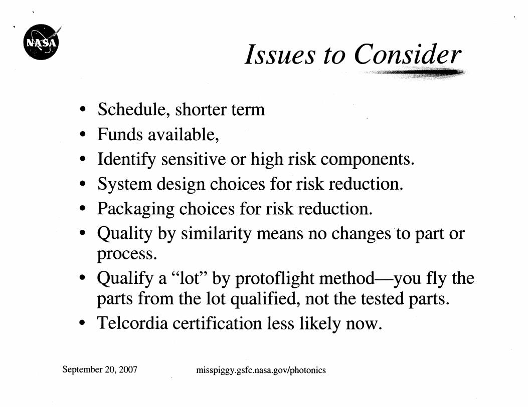
Issues to Consider
Schedule, shorter term Funds available, Identify sensitive or high risk components. System design choices for risk reduction. Packaging choices for risk reduction. Quality by similarity means no changes to part or process. Qualify a "lot" by protoflight method-you fly the parts from the lot qualified, not the tested parts. Telcordia certification less likely now.
September 20, 2007 misspiggy.gsfc.nasa.gov/photonics

-o COTS Technology Assurance Approach For
System Requirements (Instrument System Engineer) : Define critical component parameters and the quantity by how each can deviate from optimal performance as a result and during testing -- Performance requirements.
Environmental Requirements (Mechanical, Thermal, Radiation Engineers) Contamination and materials requirements. Box level random vibration, double for component Thermal environment, 10 C higher at extremes Radiation, worst case conditions.
Failure Modes Study, (Components Engineer) Conditions and Parameters,
Test Methods Tailored to capturing the largest amount of failure modes while testing for space environment.
Test Plan Contains necessary testing for mission while monitoring for failure modes.
September 20,2007 misspiggy .gsfc.nasa.gov/photonics

'0 COTS Technology Assurance
Define Crirical parameters System Requirements - Define acceptable performance parameters for port test
Define components of modules to be tested Define number of sampkes to test
Knowledge ofmaterjclls Knowiedge of constructnun des r Destructive physical analysis ( F a
I Critical Components I
Components ( Failure Modes Study I * Nodufes
Test Methods * Capture largest amount of failure modes while testing fox space experinten t
v Qualification Test Plan(s) I Contains necessdry testing for mis$ion
while monitoring for failure modes
Flow chart courtesy of Suzzanne Falvey, Northrup Grumman, based on M Ott reference: * Photonic Components for Space Systems, M. Ott, Presentation for Advanced Microelectronics and Photonics for Satellites Conference, 23 June 2004.
September 20,2007 misspiggy .gsfc.nasa.gov/photonics
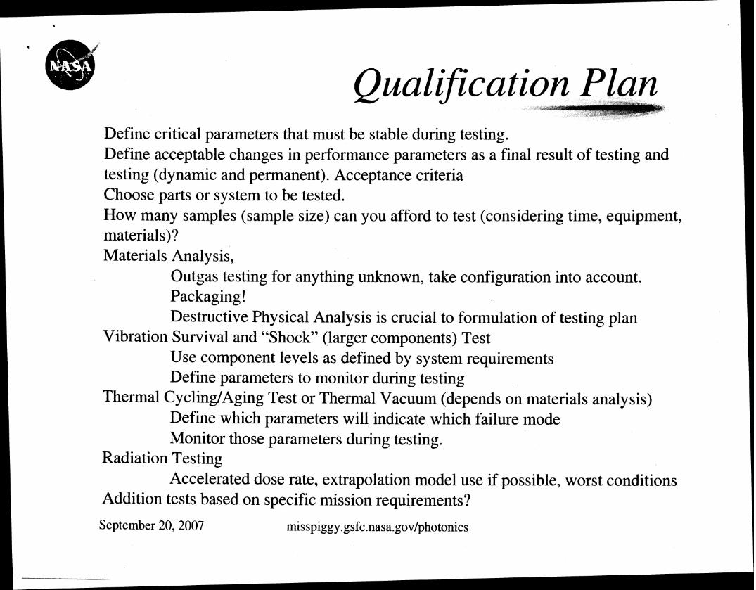
Oualification Plan Define critical parameters that must be stable during testing. Define acceptable changes in performance parameters as a final result of testing and testing (dynamic and permanent). Acceptance criteria Choose parts or system to be tested. How many samples (sample size) can you afford to test (considering time, equipment, materials)? Materials Analysis,
Outgas testing for anything unknown, take configuration into account. Packaging! Destructive Physical Analysis is crucial to formulation of testing plan
Vibration Survival and "Shock" (larger components) Test Use component levels as defined by system requirements Define parameters to monitor during testing
Thermal Cycling/Aging Test or Thermal Vacuum (depends on materials analysis) Define which parameters will indicate which failure mode Monitor those parameters during testing.
Radiation Testing Accelerated dose rate, extrapolation model use if possible, worst conditions
Addition tests based on specific mission requirements?
September 20, 2007 misspiggy .gsfc.nasa.gov/photonics

COTS Space I
Flight Outgas testing for anything unknown I
I
* Take confiqurat.ion into account E - -. .
I I Define parameters to monitor during testing Use components levels as defhed by system requirements
Vibration Survival and "Shock Teest" I i L
S
Define which parameters wd indicate which failure mode Thermal Cycling ! Aging Test * Monitor those parameters during tes ring
I i
Acc (era ted dose rate I
I Radiation Testing I I Ektrapalotion model use if possible I
B
1 t
4 Worst conditions ---- i
I Additional Tests Based on specific mksion requirements
-- I
Qualification Assurance Continued reliable per f m d n c e over life of --I- *--- - I --- ----
Flow chart courtesy of Suzzanne Falvey, Northrup Grumman, based on M. Ott reference: * Photonic Components for Space Systems, M . Ott, Presentation for Advanced Microelectronics and Photonics for Satellites Conference, 23 June 2004.
September 20,2007 misspiggy .gsfc.nasa.gov/photonics

Construction/Materials A Destructive Physical Analysis
Identify packaging issues Gases analysis, hermetic? Materials identification,
Packaging: wirebonds, die attach materials? Fluoropolymers?
Identify non metallic materials for vacuum exposure Potential contamination issues. Cure schedules -
Screening data vs. application
Construction Analysis is crucial! Long Term Reliability Will it survive harsh environments?
September 20,2007 misspiggy .gsfc.nasa.gov/photonics

Environmental Parameters
Vacuum requirements - ( Materials Analysis or Vacuum Test or both)
Vibration requirements Thermal requirements Radiation requirements Other Validation Tests
September 20,2007 misspiggy .gsfc.nasa.gov/photonics


Environmental Parameters: Vacuum Vacuum outgassing requirements:
- ASTM-E595, 100 to 300 milligrams of material 1 25 "C at 1 0-6 Ton for 24 hours Criteria: 1) Total Mass Loss c 1 %
2) Collected Volatile Condensable Materials < 0.1 % - Configuration test - Optics or laser nearby, is ASTM-E595 enough?
-ask your contamination expert
1) Use approved materials 2) Preprocess materials, vacuum, thermal 3) Decontaminate units: simple oven bake out, or vacuum? 4) Vacuum test when materials analysis is not conducted and depending
on packaging and device.
Space environment; vacuum is actually ton, best to test as close as possible for laser systems. Many chambers don't go below 1 0-7 ton.
September 20,2007 misspiggy .gsfc.nasa.gov/photonics

Environmental Parameters: Vibration
Launch vehicle vibration levels for small subsystem (established for EO- 1)
However, this is at the box level, twice the protoflight vibration values establish the correct testing conditions for the small component.
Frequency (Hz) 20
20-50
50-800
800-2000
2000
Overall
September 20,2007
Protoflight Level
0.026 g2/Hz
+6 dB1octave
0.16 g2/Hz
-6 dB1octave
0.026 g2/Hz
14.1 grms

'@ Environmental Parameters:
Launch vehicle vibration levels for small component (based on box level established for EO- 1) on the "high" side.
3 minutes per axis, tested in x, y and z
Frequency (Hz)
20
20-50
50-800
800-2000
2000
Overall
September 20,2007
Protoflight Level
0.052 g2/Hz
+6 dB/octave
0.32 g2/Hz
-6 dB/octave
0.052 g2/Hz
20.0 grms

Environmental Parameters: There is no standard, typical and benign -2 -45°C to +80°C, Telcordia; -55°C to +125"C, Military
Depending on the part for testing; Insitu testing is important, Add 10°C to each extreme for box level survival
Thermal cycles determined by part type, schedule vs. risk 30 cycles minimum for assemblies, high risk 60 cycles for assemblies for higher reliability 100 or more, optoelectronics and longer term missions.
Knowledge of packaging and failure modes really helps with cycles determination.
September 20,2007 misspiggy.gsfc.nasa.gov/photonics

-0 Environmental Parameters: Radiation
Testing for displacement damage: 3 energies in the range - 10 to 200 MeV. If you have to pick one or two energies stay in the mid range of 65 MeV and lower. Less probability of interaction at high energies. Ballpark levels: 10 -I2 p/cm2 LEO, 10-l3 p/cm2 GEO, 1 0-l4 p/cm2 for special missions (Jupiter).
I belts
(TID) devices amage
September 20,2007 misspiggy .gsfc.nasa.gov/photonics

Environmental Parameters: R
Typical space flight background radiation total dose 30 Krads - 100 Krads over 5 to 10 year mission.
Dose rates for fiber components: GLAS, 100 Krads, 5 yr, .04 radslmin MLA, 30 Krads, 8 yr, .Ol 1 radslmin (five year ave) EO- 1, 1 SKrads, 10 yr, .04 radslmin
Any other environmental parameters that need to be considered?
For example, I) radiation exposure at very cold temp, or prolonged extreme temperature exposure based on mission demands. 2 ) Motion during cold exposure.
September 20,2007 misspiggy.gsfc.nasa.gov/photonics
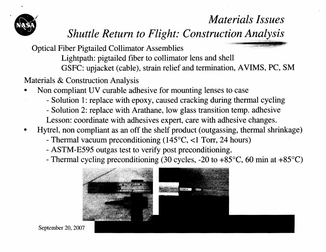
Materials Issues Shuttle Return to Flight: Construction Analysis
Optical Fiber Pigtailed Collimator Assemblies Lightpath: pigtailed fiber to collimator lens and shell GSFC: upjacket (cable), strain relief and termination, AVIMS, PC, SM
Materials & Construction Analysis Non compliant UV curable adhesive for mounting lenses to case
- Solution 1 : replace with epoxy, caused cracking during thermal cycling - Solution 2: replace with Arathane, low glass transition temp. adhesive Lesson: coordinate with adhesives expert, care with adhesive changes.
Hytrel, non compliant as an off the shelf product (outgassing, thermal shrinkage) - Thermal vacuum preconditioning (145"C, el Torr, 24 hours) - ASTM-E595 outgas test to verify post preconditioning. - Thermal cycling preconditioning (30 cycles, -20 to +85"C, 60 min at +85"C)

* @ Materials Issues: Shuttle Return to Flight Laser Di
Fitel: laser diode pigtails GSFC: Upj acket (cable), strain relief, termination, AVIMS APC SM Fitel uses silicone boot, non-compliant! Too late in fabrication process, schedule considerations to preprocess.
Cable: Thermal preconditioning, 30 cycles Hytrel boots: Vacuum preconditioning, 24 hours Kynar heat shrink tubing, epoxy: approved for space use.
Post manufacturing decontamination of entire
assembly required Laser diode rated for 85°C processing performed at
70°C
September 20,2007 misspiggy .gsfc.nasa.gov/photonics

Receik mount( and a f route s HGAS
ign
a n :ter tim d 01
Laser

* @ Vibration Qualification vs. Workmanship Testing
We refer to "profiles" by their overall total grms Each test duration 3 minutedaxis, 3 axis with insitu monitoring
Overall I 20 grms 1 14.1grms ( 10grms I
Frequency Range (Hz)
20
20-50
LOLA Qualification- 20 grms test LOLA Workmanship - 9.87 grms (X), 8.08 grms (Y), 12.89 grms (2) LR Qualification - 3 Total Tests; 20 grms, 14.1 grms, 10 grms LR Workmanship - 6.9 grms
Test 1: ASD levels
.052 g2/Hz
+6 dB/Octave
September 20,2007 misspiggy.gsfc.nasa.gov/photonics
Test 2 ASD levels
.026 g2/Hz
+6 dBIOctave
Test 3 ASD levels
.013 g2/Hz
+6 dBIOctave

Thermal Effects Thermal stability is dependent on;
Cable construction Outer diameter (smaller=more stable). Inner buffer material (expanded PTFE excellent). Extrusion methods (polymer internal stresses).
Preconditioning 60 cycles usually keep shrinkage less than 0.1 % Survival limits (hot case) is used for cycling. Cut to approximate length prior.
Termination Ferrule - Jacket isolation necessary. Polishing methods (especially at high power).
September 20,2007 misspiggy .gsfc.nasa.gov/photonics

ISS Cable Candidates; Thermal Screening for Shrinkage
Fiber Cable Candidates FO Cable Shrinkage vs. Thermal Cycle
5 10 15 20 25 30 35 40 45 50 55 60 # of Cycles
Thermal range -50 C to +I20 C, hour soak times at extremes based on current specifications of cables
Because fluoropol ymers have thermal shrinkage issues. September 20,2007 misspiggy .gsfc.nasa.gov/photonics

ISS Cable Candidates; Thermal Pre
The above cable candidates were tested for 16 hours at - 12 1 OC
Manufacturer
W.L Gore
General Cable
W.L Gore
September 20,2007 misspiggy .gsfc.nasa.gov/photonics
Part Number
FON1012,
FLEX-LITETM
OC- 1260
GSC- 13-83034-00 1.8 rnrn
Fiber Type
OFS BF05202
10011401172
Nufern (FUD-2940)
10011401172
Nufern (FUD-3 142)
62.511 251245
Thermal Range
-55 to +150°C
-65 to + 200°C
-55 to +125"C

ISS Cable Candidates; Thermal Pre 9 meters
Thermally Induced Loss of General Cable's OC-1260 10011 40 Cable,
W.L. Gore's GSC-13-83034-00 62.511 25 & FON 101 2 (1 0011 40) Cables (1310nm 8 -121 C)
I Time (hrs)

Thermal Lij Proj ec t/Type Range
Sandia/MTP with Ribbon Mated pairs, - 6 m, 100 micron GI @ 850 nm
FODBIMTP with Ribbon Mated pairs, 5.25 m, 100 micron GI @ 850 nm
MLA, Flexlite, AVIM, Mated pairs, 1 m, 200 micron, SI @ 850 nm
-30°C to +50°C
LOLA 1.75 m Flexlite, AVIM 5- Array to Fan Out, 200 um SI@ 850 nm
Cycles
-30°C to +60°C
LR I 8 m Bundle, AVIM 7- Array, 400 um @ 532 nm
photonics
-55°C to +80°C
Highest A
September 20,2007 misspiggy.gsfc.nasa.go\
Ave gain
Ave gain
-- -
Gain < 0.04 dB
< 0.06 dB, mostly gain
Ave gain

Radiation Effects Mercury Laser Altimeter Low
1 . 4 r Dose Rate Rad-Induced Attenuation for 200 (red) & 300 (blue) Flexlite Cable
r I I I I I --1
L I I I I I
0 I I
1 I I I I I
0 0.5 1 1.5 2 2.5 3 3.5 Total Dose (rads) 104
Flexlite Radiation Test, 1 1.2 radslmin at -24.1 O C
Radiation Conclusion: < .07 dB, using 1 1.2 radslmin, -24.1 "C, 26.1 in, "dark" Results for 10 m, at 30 Krads, -20°C, 850 nm, 23 radslrnin - 1 dB or 0.10 dBlm
September 20,2007 misspiggy.gsfc.nasa.gov/photonics

For 1 radmin, -50°C up to 200 Krads, Radiation Induced Atten - 0.56 dB for 10m For 1 radmin, 24°C up to 200 Krads, Radiation Induced Atten - 0.44 dB for lorn
September 20,2007 misspiggy .gsfc.nasa.gov/photonics

Radiation Testing at GSFC on Optical Fiber Candidates
Radiation Testing @ 1300 nm, OFS ovtica U A
BF05444 1 001 1401500
Attenuation
BF05202 100/1401172 RH
Temp
0.1 radslmin
BF05202 10011401172 RH
TID Part
100 Krad
14.2 radslmin
CF04530 10011401172 S
Dose Rate
42 radslmin
CF04530 10011401172 S
5.1 Krad
14.2 radslmin
BF0443 1 62.511 251250
-125°C
100 Krad
42 radslmin
BF0443 1 62.511 251250
-125°C
5.1 Krad
0.1 radslmin
-125°C
100 Krad
0.1 radslrnin
-125°C
100 Krad
100 Krad
-25°C 0.91 dB/m

'@ Radiation Effects on Rare Earth Fiber for Lasers Paper Survey
Aluminum content increases radiation induced e
* Fiber also contains 5.0 mol% Germanium. Data at 830 nm, 180 radslmin.
Yb (mol%)
0.13*
0.18
Rare Earth dopant (Er) does not dominate over radiation performance [2]
A1203 (mol%)
1 .O
4.2
84 radslmin upto 50 Krad, 3 m under ambient
Part
HE980
HG980
P,O, (mol%)
1.2
0.9
Er Content
4.5 /m3
1.6 1025/m3
TID Krad
14
14
Rad Induced Atten.
1 dBlm
12 dBlm
A1
(%mol wt)
12
10
Ge
(%mol wt)
20
23
Sensitivity 980 nm, dB/m Krad
.013
.012
Sensitivity 1300 nm, dB/m Krad
.004 1
.0038

.@ Radiation Effects on Rare Earth Fiber for Lasers Paper Survey
Low Dose Rate, .038 radslmin extrapolation for HE980
Also shows wavelength dependence, consistent with other COTS fiber. Yb and Er doped fibers are equivalent in terms of sensitivity. Lanthanum doped fibers are extremely sensitive at - 10's dBlm. Yb and Er doped fibers exhibit saturation behavior. Proton and gamma exposures show similar results.
To compare sensitivity to typical 1001140 at 100 Krads
Wavelength
980 nm
1300 nm
1550 nm
Total Dose
100 Krad
100 Krad
100 Krad
Temp
25°C
50°C _r
Radiation Induced Attenuation
0.91 dBlm
0.26 dBlm
0.14 dBlm .
h nm
1310
850
Dose rate
.Olrads/min
-032 radslmin
Sensitivity
1.7 10-4 d ~ l m
2.0 10-4 dB/m
Reference M. Ott, SPIE Vol. 3440.
M. Ott, IEEE NSREC Data Workshop 2002.
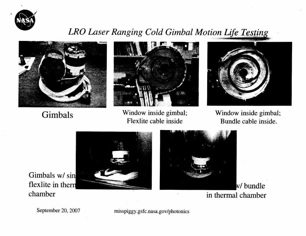
LRO Laser Ranging Cold Gimbal Motion Life Testing
Gimbals Window inside gimbal; Window inside gimbal; Flexlite cable inside Bundle cable inside.
chamber in thermal chamber
September 20,2007 misspiggy.gsfc.nasa.gov/photonics

* @ LRO Laser Ranging Simplex Cold Gimbal Motion Life Test Single Strand of Flexlite 3001330 Ca
Results of Test 3 at -20°C, Last few gimbal cycles, flex 1
Gimbal Positions and Optical Insertion Loss@-20C From 5454 to 5460 cycles
(Note: The fiber is tight at 0 position and loose at 180) - - - - -- -- - - - --- - 1 + Optical Insertion Loss 1 --T 200
I 1 September 20,2007 misspiggy .gsfc.nasa.gov/photonics

@A0 Laser Ranging Bundle Cold Gimbal Motion Testing Results
End of Test, relative IL - 0.50 dB. @ 850 nm. -20°C -
Gimbal Positions and Optical Insertion Loss 8-2OC Fiber #4 8 850nm with 19295 to 19300 cycles I
(Note: The fiber is tight at 0 position and loose at 180) --- -- -__-
-e Insertion Loss(dB)
Date & Time
September 20,2007 misspiggy.gsfc.nasa.govlphotonics

International Space Station 2000
Failure Analysis: Optical Fiber Cable 1999-2000
Failure Analysis: Optical Fiber Termini 2005-2006
Bad Combination
~ -~ . --- - -~~ ~. . .. - - ~ -- -
Ghss Fiber Hermetic Seal
Fiber Optic Cable "Rocket Engine" Defects Hermetic coating holes, Polyimide coating holds water Fluorine generated during extrusion of buffer Hollow tube construction
water and fluorine interaction results in HF acid HF etches pits into fiber getting through holes in coating Etch pits deep into the core caused losses and cracks
September 20,2007 misspiggy .gsfc.nasa.gov/photonics

International Space Station Study on Te
Vendor provided termini that somehow passed integration QA During integration by the contractor. Node 2 welded into place. Cost of changing termini on Node 2 more than $1 M. Node 3 fixed.
Termini end faces were found to be cracked after failing insertion loss testing during integration.
September 20,2007 misspiggy.gsfc.nasa.gov/photonics

The below cross section of the terminus shows a concave end-face. This is per specification. If the end- face were convex, the glass would likely experience an impact when connected, causing a fracture.
September 20,2007
ISS Termini Failure Analysis
The fiber must be free of cracks in order to prevent a degraded or blocked optical signal. If a glass fiber has a crack after the polisl process, the crack will grow ove
ling !r
/ Ferrule P3r Fiber End View
/ The end-face of this optical fiber is 140pm. If dirt is present, the optical signal would be degraded or blocked#

ISS FA Optic
Fiber Most Likely to Fail Because of Crack
Optical Microscopy:
@Bright field (Top) & dark field (Bottom) illumination (taken at 200X) can be used to enhance certain features of the terminus. *At 200X, a crack formation can be seen, and the "smudge" appears to be sub-surface cracking. .More information is required to characterize the crack. @Optical microscopy is not enough to identify an origin of the crack, so SEM will need to be performed.

ISS FA Scanning Electron Microscopy
Fiber Most Likely to Fail Because of
1 could be
~erved and
.ce cannot nus must

ISS FA: Confocal Microscopy
Confocal Microscopy:
Confocal microscopy scans the surface of the terminus & displays the contour of the fiber end-face.
The convex surface shown at the bottom left, would increase the likelihood of an impact when connected.
The specification for end-face geometry is to be concave (bottom right) to reduce the risk of impact damage. 4 out of 10 termini returned, violate this spec.
Sample of a 1 convex profile ',
(noncompliance , . . , ,
with 131
specification)
September 20,200 misspiggy .gsfc.na
Sample of a concave profile (specification compliant)

Manufacturing of Fiber Polyimide I Coating
Fiber Manufacturing:
.Note the off-center orientation of the fiber to the coating. This would cause measurable signal loss if mated to a fiber that has a concentric coating, and higher loss if mated to an identical fiber with the eccentricity 180" out.
This eccentricity is a violation of the spec. Spec #SSQ 21654 sec 3.7 indicates that there should be
no "thin spots" in the coating of the fiber. The terminus should not have passed QA and should
have been rejected at the manufacturer's site. GSFC would have rejected this termination & would
have required a re-termination be performed. Note how the cracks emanate from the thick coating. Unbalanced stress would have been applied to this fiber
during the epoxy cure process, accelerating crack growth.

4
Manufacturing Lessons Learned Summary
Identified Process Issues: Fiber Manufacturing - Added stress induced by non-concentric coating application. Epoxy cure -GSFC uses epoxy cures as low as possible to reduce the CTE stress. End-faces should be verified. Polishing -GSFC uses fpw rit la ping film and never more than 0.5pm grit for rework. ,-Y{a1 -a$*AT
Quality Assurance - If end-faces cannot be cleaned, they should be inspected at higher magnifications for possible damage, 200X is the GSFC requirement.
September 20,2007

Lessons Learned and Learning: Passive Components
Always perform materials analysis which may inclu physical analysis. If materials analysis is not performed please plan to do thermal cycling vacuum testing. Failure mode of delamination for LD coupled fiber or gain fiber may not show up during insitu monitoring as a degradation or failure mode. Final inspections on termini end faces shall be performed at 200 X prior to shipment for integration and inspected prior to integration for cleanliness. Cure schedules for larger core graded index fibers especially should be as close the lower bound of the operation temperature range as possible. High temp cure sets up a high stress situation. Just because you see a cure schedule in the outgassing.nasa.gov database that passes TML and CVCM requirements, doesn't mean you have to follow the cure schedule listed. Graded index 100/140 is extremely brittle. .special care required during termination and integration. Connector assemblies; decouple cable stresses from connector body
September 20,2007 misspiggy.gsfc.nasa.gov/photonics

Conclusion All components are not appropriate for all applications. Knowledge of failure modes and materials is crucial to making feasibility decisions as well as design, manufacturing procedures and test plans.
Thank you for the invitation!
For more information please visit the website:
misspiggy .gsfc.nasa.gov/photonic~
September 20,2007