Qualification of Fiber Optic Cable for NPP · Fiber optic at Dukovany NPP Fiber optic cables are...
19
Zuzana ŠARŠOUNOVÁ Vít PLAČEK Petr HAVRÁNEK [email protected] Qualification of Fiber Optic Cable for NPP International Meeting on Equipment Qualification In Nuclear Installations UJV Rez, Czech Republic May 20 – 23, 2019
Transcript of Qualification of Fiber Optic Cable for NPP · Fiber optic at Dukovany NPP Fiber optic cables are...
Zuzana ŠARŠOUNOVÁ
Vít PLAČEK
Petr HAVRÁNEK
Qualification of Fiber Optic Cable for NPP
International Meeting on Equipment Qualification
In Nuclear Installations
UJV Rez, Czech Republic
May 20 – 23, 2019
1
Fiber optic cables become more and more important in the
nuclear industry.
Fiber optic instrument channels in nuclear power plants offer
several advantages over traditional electrical conductor,
including:
• increased immunity to electromagnetic interference (EMI),
• high transmission bandwidth,
• smaller size.
Increasing the use of fiber optic instrumentation in other
industries has resulted in lower costs and a wider range of
product availability.
2
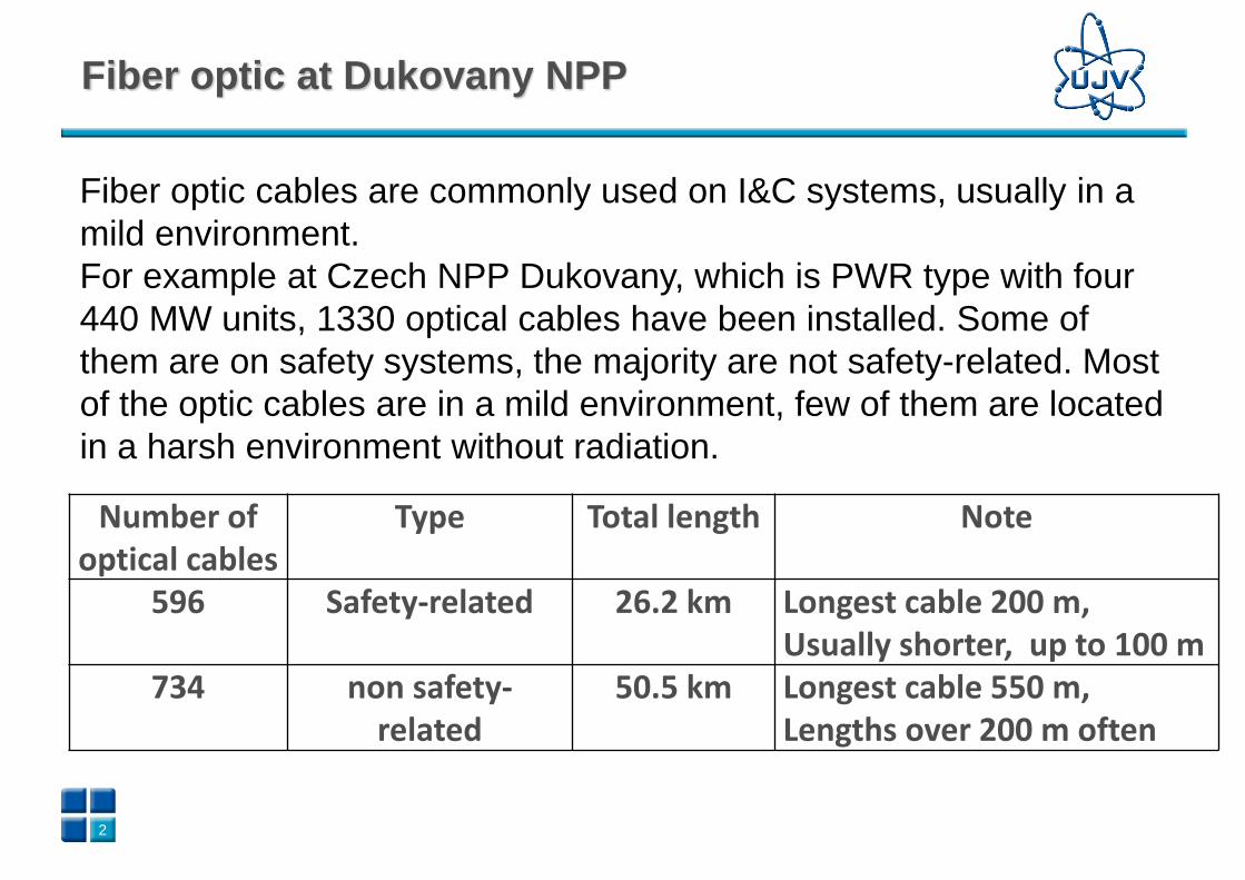
Fiber optic at Dukovany NPP
Fiber optic cables are commonly used on I&C systems, usually in a
mild environment.
For example at Czech NPP Dukovany, which is PWR type with four
440 MW units, 1330 optical cables have been installed. Some of
them are on safety systems, the majority are not safety-related. Most
of the optic cables are in a mild environment, few of them are located
in a harsh environment without radiation.
Number of optical cables
Type Total length Note
596 Safety-related 26.2 km Longest cable 200 m, Usually shorter, up to 100 m
734 non safety-related
50.5 km Longest cable 550 m, Lengths over 200 m often
3
Application of safety-related fiber optic cables in a harsh
environment with demand on functionality during LOCA needs their
qualification.
This standard was issued first time in 2011, but it was approved as a
full-use standard in the middle of 2013.
The international standard for qualification IEEE 1682-2011:
Standard for Qualifying Fiber Optic Cables, Connections, and
Optical Fiber Splices for use in Safety Systems in Nuclear Power
Generating Stations
4
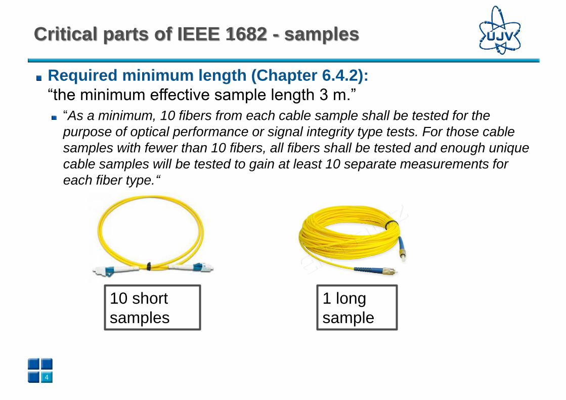
Required minimum length (Chapter 6.4.2):
“the minimum effective sample length 3 m.”
“As a minimum, 10 fibers from each cable sample shall be tested for the
purpose of optical performance or signal integrity type tests. For those cable
samples with fewer than 10 fibers, all fibers shall be tested and enough unique
cable samples will be tested to gain at least 10 separate measurements for
each fiber type.“
10 short
samples
1 long
sample
Critical parts of IEEE 1682 - samples
5
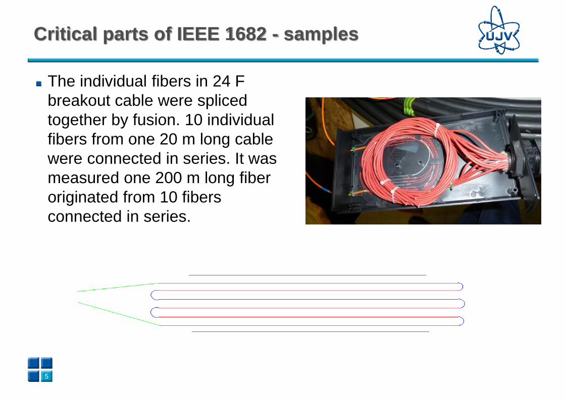
The individual fibers in 24 F
breakout cable were spliced
together by fusion. 10 individual
fibers from one 20 m long cable
were connected in series. It was
measured one 200 m long fiber
originated from 10 fibers
connected in series.
Critical parts of IEEE 1682 - samples
6
Critical parts of IEEE 1682 - ageing
Thermal ageing should be performed at the maximum humidity
conditions specified for normal service conditions (Chapter
6.4.2.b):
When the thermal ageing is carried out above the temperature 100°C the
humidity level can’t be regulated at normal atmospheric pressure. To follow
strictly the standard, the ageing shall be carried bellow 100 °C, which will
prolong the ageing time.
7
Critical parts of IEEE 1682 – seismic test
Connection assemblies shall be seismically qualified using the
test methods described in IEEE Std 344- 2004. The connection
assembly mounting for this test shall simulate the intended
service configuration and installed conditions including
consideration of external cabling (Chapter 6.4.4):
Permanent connections that are made using the method of fusion splices are
not mentioned. Our preliminary experience shows fusion sensitivity to
irradiation. Hence, we would recommend performing a seismic test also on
fiber fusions.
8
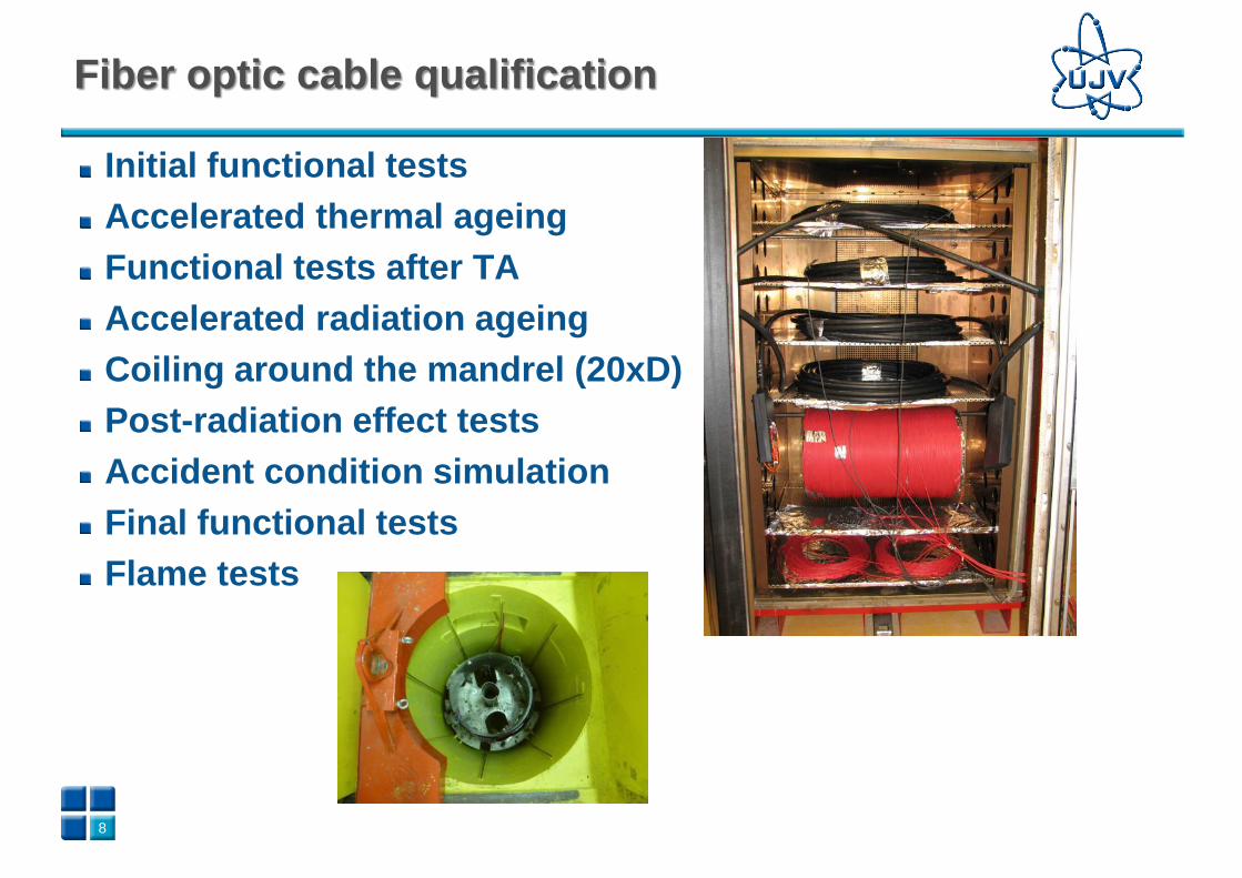
Initial functional tests
Accelerated thermal ageing
Functional tests after TA
Accelerated radiation ageing
Coiling around the mandrel (20xD)
Post-radiation effect tests
Accident condition simulation
Final functional tests
Flame tests
Fiber optic cable qualification
9
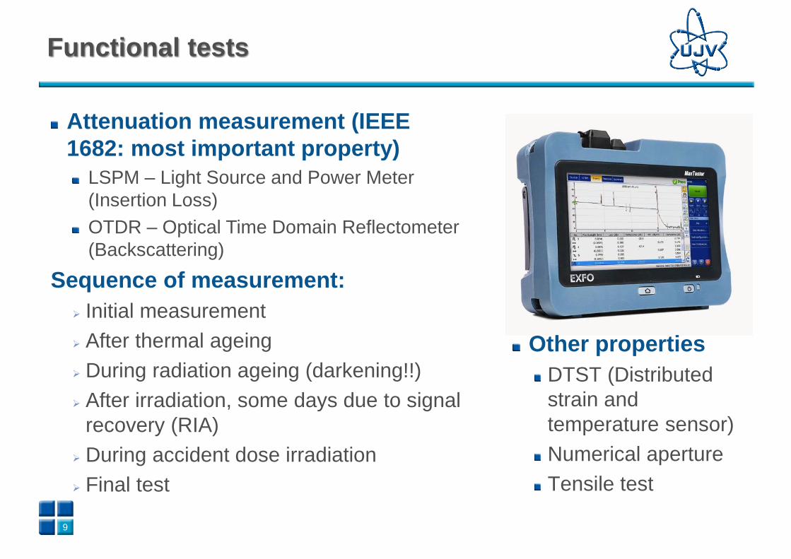
Attenuation measurement (IEEE
1682: most important property)
LSPM – Light Source and Power Meter
(Insertion Loss)
OTDR – Optical Time Domain Reflectometer
(Backscattering)
Sequence of measurement:
➢ Initial measurement
➢ After thermal ageing
➢ During radiation ageing (darkening!!)
➢ After irradiation, some days due to signal
recovery (RIA)
➢ During accident dose irradiation
➢ Final test
Functional tests
Other properties
DTST (Distributed
strain and
temperature sensor)
Numerical aperture
Tensile test
10
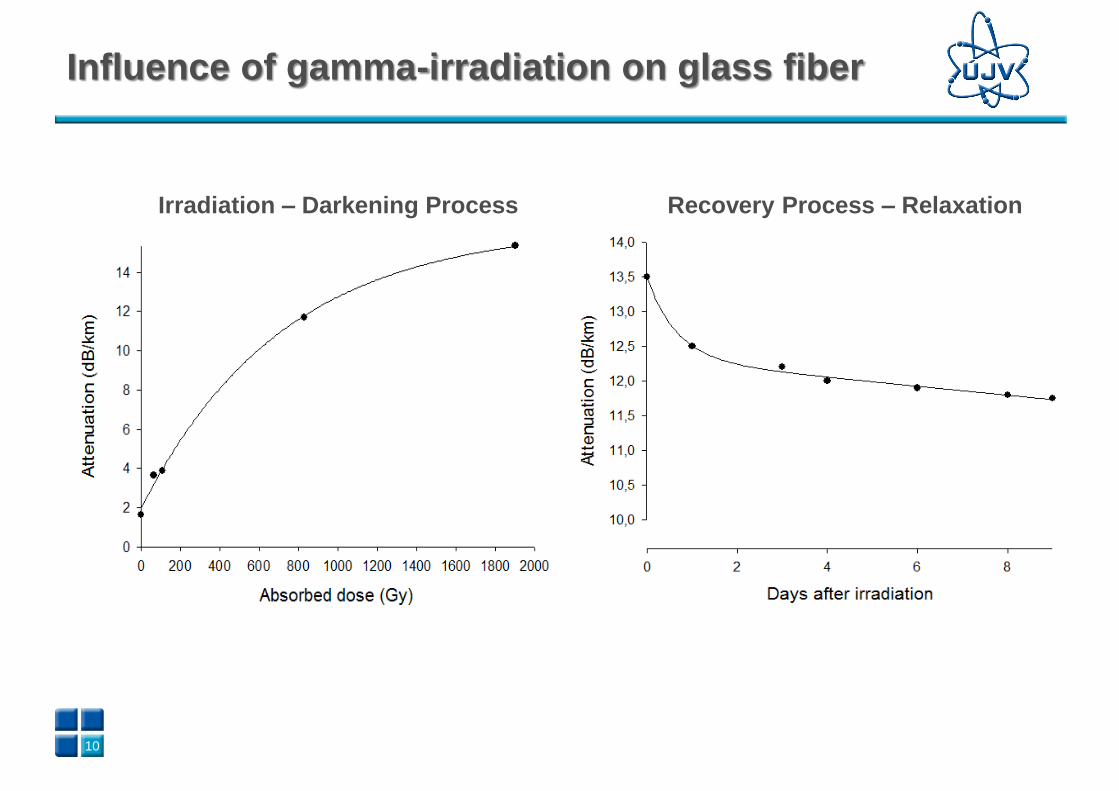
Irradiation – Darkening Process Recovery Process – Relaxation
Influence of gamma-irradiation on glass fiber
11
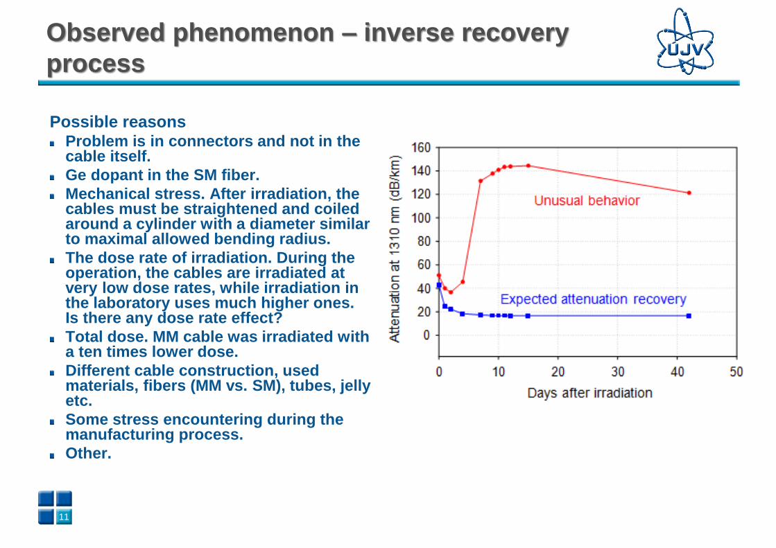
Possible reasonsProblem is in connectors and not in the cable itself.
Ge dopant in the SM fiber.
Mechanical stress. After irradiation, the cables must be straightened and coiled around a cylinder with a diameter similar to maximal allowed bending radius.
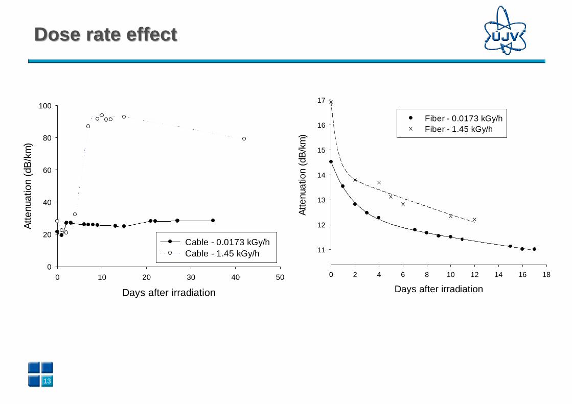
The dose rate of irradiation. During the operation, the cables are irradiated at very low dose rates, while irradiation inthe laboratory uses much higher ones. Is there any dose rate effect?
Total dose. MM cable was irradiated with a ten times lower dose.
Different cable construction, used materials, fibers (MM vs. SM), tubes, jelly etc.
Some stress encountering during the manufacturing process.
Other.
Observed phenomenon – inverse recovery
process
12
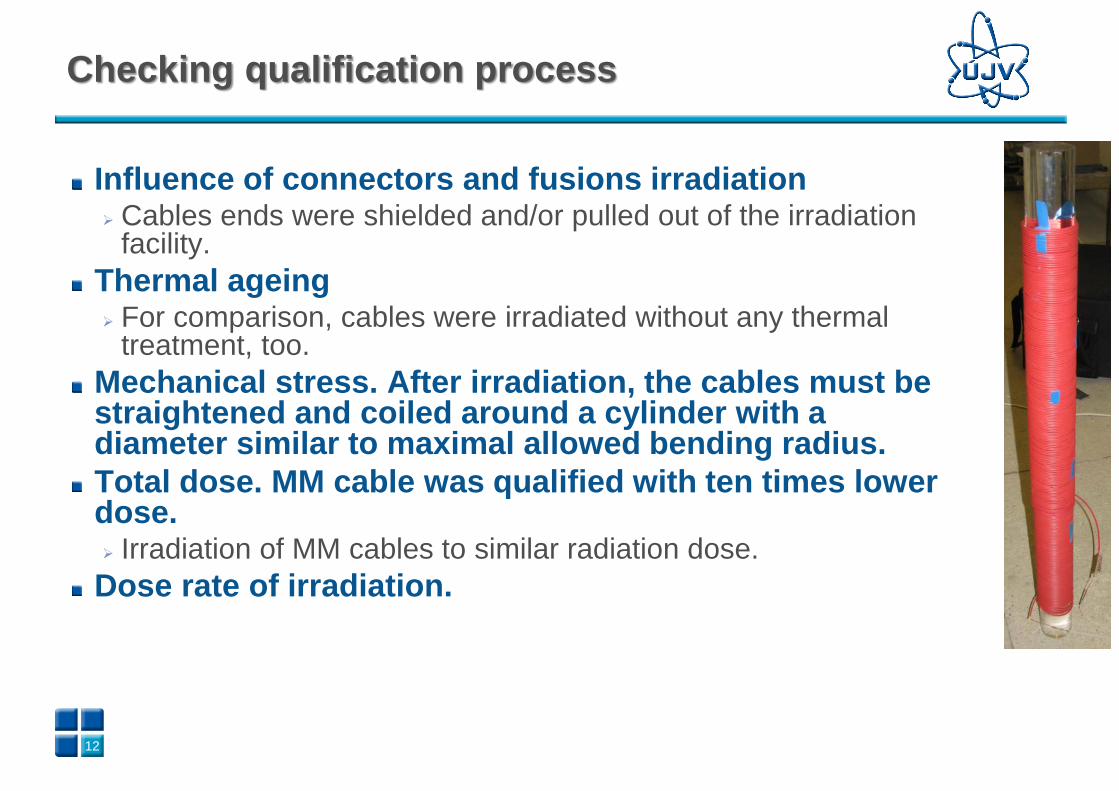
Influence of connectors and fusions irradiation➢ Cables ends were shielded and/or pulled out of the irradiation
facility.
Thermal ageing➢ For comparison, cables were irradiated without any thermal
treatment, too.
Mechanical stress. After irradiation, the cables must be straightened and coiled around a cylinder with a diameter similar to maximal allowed bending radius.
Total dose. MM cable was qualified with ten times lower dose.➢ Irradiation of MM cables to similar radiation dose.
Dose rate of irradiation.
Checking qualification process
13
Days after irradiation
0 10 20 30 40 50
Att
enua
tio
n (
dB
/km
)
0
20
40
60
80
100
Cable - 0.0173 kGy/h
Cable - 1.45 kGy/h
Days after irradiation
0 2 4 6 8 10 12 14 16 18
Att
enua
tio
n (
dB
/km
)
11
12
13
14
15
16
17
Fiber - 0.0173 kGy/h
Fiber - 1.45 kGy/h
Dose rate effect
14
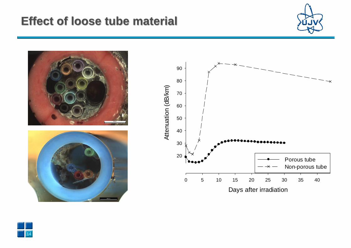
Days after irradiation
0 5 10 15 20 25 30 35 40
Att
enua
tio
n (
dB
/km
)
20
30
40
50
60
70
80
90
Porous tube
Non-porous tube
Effect of loose tube material

15
Days after irradiation
0 5 10 15 20 25 30
Att
enua
tio
n (
dB
/km
)
10
15
20
25
30
35
Gel loose tube with 4 fibers
Gel loose tube with 12 fibers
Dry loose tube with 4 fibers
Types of loose tubes effect
16161616
Conclusion
Qualification of optical cables will become increasingly common
The standard IEEE 1682 is the first international standard that covers the basic procedure of qualification testing for fiber optic cable operating in the harsh environment of NPP.
This presentation discusses some practical testing experience open questions and problems that are not included in the standard, or not prescribed properly.
In ÚJV, we discovered an unusual phenomenon “inverse recovery process”
It has been proved, that
▪ The glass material of used fiber,
▪ mechanical stress,
▪ radiation dose rate
▪ The material of the loose tubedo not cause the inverse recovery process.
We suppose that this is caused by cable construction. The jelly probably goes through some physical and/or chemical changes and causes the inverse recovery process.ORRadiation creates hydrogen species that can go through the fiber coating up to the fiber core, interact with created point defects and create Si-OH.
17171717
• Thanks to colleagues from VŠB (Technical University of
Ostrava) for measuring and supports.
• Czech Technology Agency project “Development of the
method for accelerated ageing of passive photonic components
with orientation to plants with higher degree of ionizing
radiation occurrence,” project No. TK01020162.
Acknowledgement
18
Thank you for your attention
E-mail: [email protected]
Phone: +420 266 173 579
Hlavní 130, Řež, 250 68 Husinec
Czech Republic
www.ujv.cz