Fiber Optic Cable Qualification Update · Fiber Optic Cable are utilized to connect the computers,...
22
Fiber Optic Cable Qualification Update EQTM 2018 Eric Rasmussen RSCC Wire and Cable LLC E [email protected] Terry Price Ontario Power Generation [email protected] 1
Transcript of Fiber Optic Cable Qualification Update · Fiber Optic Cable are utilized to connect the computers,...

Fiber Optic Cable Qualification Update
EQTM 2018
Eric RasmussenRSCC Wire and Cable LLC
Terry PriceOntario Power Generation
1

Plant Refurbishment – Life Extension• Part of CANDU design• Multi-year project• Replacement of major
reactor components and upgrade key plant systems
• 30 plus more years of clean, safe, reliable operations
Darlington Nuclear Generating StationIn Service 1993 - 4 Units each generating approximately 900 Megawatt (gross electrical)
2

As part of the Darlington Refurbishment Project the Shutdown System Display / Test Computers are replaced due to hardware obsolescence.
The Shutdown System Display / Test Computers displays in the Main Control Room giving operating and Post Accident Monitoring data.
Field sensors and associated instrumentation monitor various trip parameters and provide signals to the trip computers. These computers perform conditioning of trip parameters and provide real-time display signals and trip signals should a parameter exceed set point.
3

Fiber Optic Cable are utilized to connect the computers, while maintaining electrical isolation. Their reliable operation is important for Darlington life extension.
The original design used coaxial cable that could not be qualified for the DBA Harsh Environment it was routed (end equipment is not in a harsh environment).
Operations “work around” used Reactor Power (PAM) monitoring from the Units Secondary Control Area (Emergency Control Room) until the coax was replaced with Fiber Optic Cable.
Fiber Optic Cable provides a faster response time and better quality of transmitted data.
4

Environmental Qualification Summary Sheets
Equipment Description Parameter Value Documentation References Qual.
Method Notes
Required Demonstrated Required Demonstrated
System: SDS1 and SDS2
Mission Time 90 Days 90 Days Ref 4, 5 and 6 3, Tab E1, Sec 3.2 Test 6
Equipment Tag: 68200 / 68300
See Note 1 and Tab 2.3
Peak Temperature (°C) 163 171 1, Sec 5.3.3.1, Fig T6
3, Tab E1, Sec 3.1 Test 7
Equipment Description:
See Note 2
Peak Pressure [kPa(g)] 2.5 827 1, Sec 5.3.3.2, Figure P2
3, Tab E1, Sec 3.1 Test 8
Relative Humidity (%) 100 100 1, Sec 5.3.3.4, Figure H1
3, Tab E1, Sec 3.1 Test 9
Manufacturer: RSCC® (Formerly Rockbestos) See Note 2
Chemical Effect(s) Yes Yes 1, Sec 5.3.3.6 3, Tab E1, Sec 4.2 Analysis 10
Model Number:
FF08500-000
Radiation (rads T.I.D.) 1.1005265E6 1.17E6 1, Sec 5.3.3.3, Table NR5,
3, Tab E1, Sec 6.1 Test 11
EQ Function/Service:
See Note 3
Thermal Aging Life (yrs.) N/A >60@45°C N/A 3, Tab E1, Sec 7.1 and Tab MD 2.2
Test 12
Cycle Aging (No. Cycles) No No N/A 3, Tab E1, Sec 8.2 N/A 13
Unit(s): 1234
Qualified Life (yrs.) N/A 60 Years N/A 3, Tab E1, Sec 9.1 Test 14
Location(s):
See Note 4 and Tab MD1.2
Submergence No No See Note 15 3, Tab E1, Sec 5. N/A 15
Performance Criteria See Note 16 See Note 16 See Note 16 3, Tab E1, Sec 11.1.
Test 16
Qualification Category:
Category 1, 2, or 3, See Note 5
Category 1 Electrical Interface Requirements
Note: None. Splices and terminations are in a mild environment. ( See Note 2)
Mechanical Interface Requirements:
Note: None
( See Note 2)
5

Background• IEEE 1682-2011: IEEE Standard for Qualifying Fiber Optic
Cables, Connections, and Optical Fiber Splices for Use in Safety Systems in Nuclear Power Generating Stations
• Trial-use standard published in 2011– The standard “provides requirements, directions, and methods for qualifying
fiber optic cables, connections, and optical fiber splices for use in safety systems of nuclear power generating stations.”
• Standard was affirmed in 2013– There were not any comments made during the trial-use period. – Today IEEE 1682 is recognized as a ‘Standard’ by IEEE.
• IEEE White Paper is scheduled to be published shortly– The paper intends to provide background and guidance on significant topics
that were discussed during the standard’s creation and those topics which were deferred for subsequent revisions.
• Working Group is currently being formed for the 2021 revision6

Fiber versus Cable Qualification• The principles of qualification are identical for fiber and
electrical cable, though there are significant differences in the application to fiber optic cable as compared to electrical cable
• EMI– Fiber optic cables are largely immune to the affects of electromagnetic
interference (EMI).
• Ohmic heating– Optical fibers carry very limited power, therefore, internal heating is
insignificant and can be disregarded.
• Radiation Induced Attenuation (RIA)– Optical attenuation (i.e. power loss) may render the fiber and/or end-device
inoperative. – Optical fibers are especially sensitive to increased attenuation when exposed
to radiation: • Higher dose rates and higher total dosage results in greater RIA• Higher temperatures reduce RIA• Recovery of RIA may occur after the radiation source is removed
7
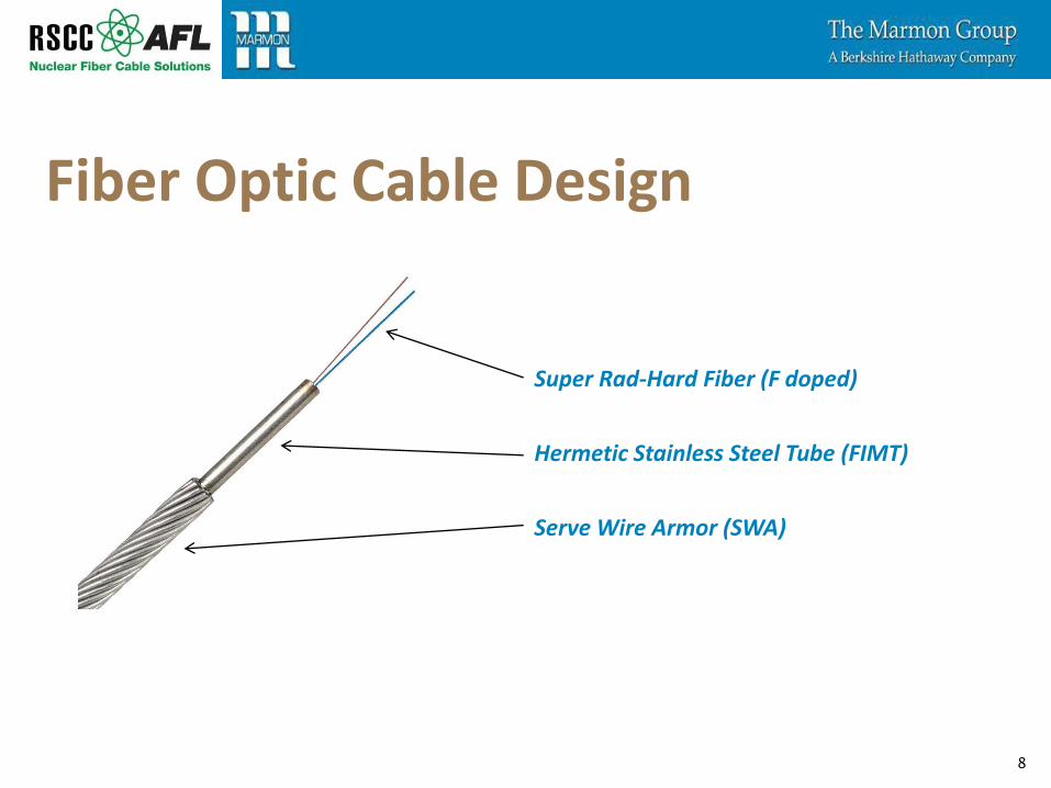
Super Rad-Hard Fiber (F doped)
Hermetic Stainless Steel Tube (FIMT)
Serve Wire Armor (SWA)
8
Fiber Optic Cable Design

Core (F doped glass)
Cladding (glass)
Coating(s) (polymeric)
9
Fiber Optic Cable Design

IEEE 1682 (EQ) Qualification • Aging properties (section 6.4.1):
• IEEE 1682-2011 section 6.4.1 requires that “where significant aging mechanisms are identified, suitable age conditioning shall be included in the type test.” IEEE 1682-2011 section 6.4.1 requires that “aging data shall be used to establish the activation energy of the critical materials.”
– Thermal aging data was established for all polymeric layers utilized which only applies to the fiber coatings.
– Since the glass fiber and stainless steel tube are inert materials without significant aging mechanisms, then thermal aging data was not required for either component.
10

IEEE 1682 (EQ) Qualification • Draft IEEE 1682 White Paper States:
• “The optical fiber is coated with a single or composite nonconductive, thin, polymerized layer(s) that function to protect the fiber from mechanical damage and moisture ingress. The protective coating(s) acts to cushion the glass fiber from mechanical forces which could create micro bends in the fiber, thereby minimizing optical signal loss. The coating(s) also act as a moisture barrier, thereby preventing micro-crack propagation. Since the fiber coating(s) are critical to the safety function of the fiber, the Arrhenius method may be used to establish a qualified life for the coating(s).”
11

IEEE 1682 (EQ) Qualification • Thermal Aging and Activation Energies:
• Samples were thermally aging at 105°C for 168 hours
Polymeric Layer Activation Energy Qualified Life
Inner Coating 1.679 eV >70 years at 45°C
Outer Coating 1.418 eV 70 years at 45°C
12

13

IEEE 1682 (EQ) Qualification • Test samples:
• Sample Set #1: Unaged and Un-irradiated
• Sample Set #2: Unaged and 1.1 Megarads
• Sample Set #3: 60 years aged and 1.1 Megarads
– Based upon IEEE 1682-2011, Paragraph 6.4.1.2, since the fiber which was qualified is known to exhibit the phenomena of “recovery” following radiation aging, then thermal aging was performed prior to radiation aging which achieved the worst postulated state of degradation. Furthermore, simultaneous thermal and radiation aging was not performed since higher temperatures during radiation exposure would have exacerbated the “recovery” effect and produced a better postulated condition than what may be observed in the fiber optic cable’s actual installed environment.
14

IEEE 1682 (EQ) Qualification • Gamma radiation exposure:
• 1.1 Megarads total integrated dosage (TID) was based on a 2σ confidence level
15

16

IEEE 1682 (EQ) Qualification • Normal service use
testing:
• Following thermal and radiation aging:
– samples were straightened– … bent around mandrel
equal to fiber’s minimum bend radius
– … visual examination– … optical power loss was
measured on every fiber
17

IEEE 1682 (EQ) Qualification • DBE simulation performed at RSCC test laboratory:
18

19
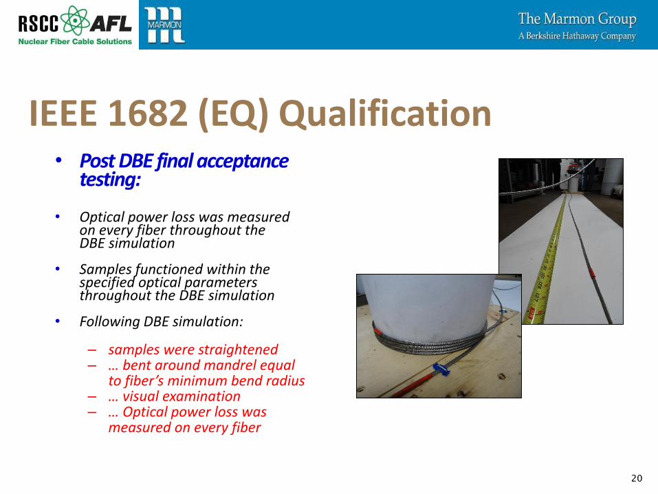
IEEE 1682 (EQ) Qualification • Post DBE final acceptance
testing:
• Optical power loss was measured on every fiber throughout the DBE simulation
• Samples functioned within the specified optical parameters throughout the DBE simulation
• Following DBE simulation:
– samples were straightened– … bent around mandrel equal
to fiber’s minimum bend radius– … visual examination– … Optical power loss was
measured on every fiber
20

IEEE 1682 (EQ) Qualification • Anomalies:
• 1 due to alternative optical measurement methodology employed for normal service testing
• 1 due to an optical switch malfunction during the irradiation exposure
• 1 due to DBE test chamber falling below the required profile
21

Thank You!
22
Eric RasmussenRSCC Wire and Cable LLC
Terry PriceOntario Power Generation