
SMALL DIAMETER BEVELER SDB 206/2 - … · SMALL DIAMETER BEVELER SDB 206/2 ... Hemos reunido una...
62
Part Number: 56-MAN-01 Revision No: 1 i Revised Sept. '00 SMALL DIAMETER BEVELER SDB 206/2 Enter Your Machines Serial Number Here For Proper Record Keeping and Ordering Reference. TUBE & PIPE TUBE & PIPE TUBE & PIPE TUBE & PIPE TUBE & PIPE CUT CUT CUT CUT CUT-OFF MA -OFF MA -OFF MA -OFF MA -OFF MACHINES CHINES CHINES CHINES CHINES Mod. SDB 206/2 S/N
Transcript of SMALL DIAMETER BEVELER SDB 206/2 - … · SMALL DIAMETER BEVELER SDB 206/2 ... Hemos reunido una...

Part Number: 56-MAN-01
Revision No: 1
i
RevisedSept. '00
SMALL DIAMETERBEVELERSDB 206/2
������������ ��������������������������
���������������������������������������������
TUBE & PIPETUBE & PIPETUBE & PIPETUBE & PIPETUBE & PIPECUTCUTCUTCUTCUT-OFF MA-OFF MA-OFF MA-OFF MA-OFF MACHINESCHINESCHINESCHINESCHINES
Mod. SDB 206/2 S/N


SDB 206/2 SMALL DIAMETER BEVELER
TABLE OF CONTENTS
SECTION I. INTRODUCTION TO OPERATOR .............................................................................. 4
SECTION II. STANDARD EQUIPMENT .......................................................................................... 5
SECTION III. SAFETY INSTRUCTIONS ....................................................................................... 6-9
SECTION IV. CE DECLARATION OF CONFORMITY .................................................................... 10
SECTION V. SDB 206/2 SET-UP & OPERATING PROCEDURES ............................................11-20
A. SDB 206/2 Mandrel Selection ............................................................................... 12
B. Mandrel Placement ............................................................................................... 12
C. Form Tooling Set-up ............................................................................................. 12
D. Mounting SDB 206/2 to Pipe ............................................................................... 13
E. Continuous Operation ........................................................................................... 13
F. Tips for a good finish ............................................................................................ 13
G. Flange Facing Conversion Procedure ................................................................... 14
H. Flange Facing Setup & Operating Procedures ..................................................15-20
SECTION VI. MAINTENANCE ........................................................................................................ 22
SECTION VII. MISCELLANEOUS CHARTS & GRAPHS ............................................................23-30
SECTION X. PARTS LISTS AND EXPLODED VIEW DRAWINGS ...........................................31-57
206/2 Beveling Machine Assembly .......................................................................32-33
56-000-01 Pneumatic Drive Assembly...................................................................34-35
56-305-00 Electric Drive assembly ........................................................................36-37
56-413-00 Hydraulic Drive Assembly .....................................................................38-39
Captivated Leg Mandrel .........................................................................................40-41
3-Jaw Independent "Short Perch" Mandrel ............................................................42-43
3-Jaw Independent "Short Perch" Mandrel (for 3-6.08" I.D.) ..................................44-45
Obsolete Standard Mandrel ...................................................................................46-47
Collet Mandrel Tube & Pipe ...................................................................................48-49
56-421-00 SDB 206/2 Flange Facing Conversion Kit .............................................50-53
56-404-00 SDB 206/2 Flange Facing Module .........................................................54-55
56-414-01 Mandrel Assembly ................................................................................56-57
Air Motor Shematic ...............................................................................................58-61
SECTION XI. ORDERING INFORMATION ..................................................................................... 62

SDB 206/2 SMALL DIAMETER BEVELER
4
I. INTRODUCTION TO OPERATOR
The Wachs Model SDB206 was designed for produc-tion pipe beveling on pipe with 2.28" to 6.58"(57.91mm–167.13mm) I.D.* It utilizes form cuttersmade from high speed steel or carbide that cansimultaneously bevel, counterbore and prepare theland in one operation. It features a unique two man-drel system with adapters to cover its full range. TheWachs Model SDB206 is manufactured with heavyduty bearings and bushings to ensure its reliability foruse on a production basis. Please read this manualthoroughly before attempting to use this tool.
FAST SETUP· Set up and operate from storage case to pipe in under 10minutes.· “QUICK CHANGE “ extension legs use captivatedfasteners to mount firmly to mandrel.· One adjustment, universal three leg chuck automaticallycenters and squares the machine in pipe I.D.· Install or adjust tool bits in seconds.
EASY OPERATION· Convenient “Fail safe” on/off motor valve.· Adjustable hand grip speed control.· In-feed hand wheel with indices for precise measurement.· Adjustable dual key design makes tool feed
easy, absorbs torque, reduces operator fatigue andincreases safety.
· Compact design requires minimal radial clearance of only2.25"
· Powerful 1-1/2 horse power air motor easily machines.750"( 19.05 mm) wall stainless pipe or tube.
· Setup square in elbows, tees, and valves with adjustable 3-leg fitting mandrel.
VERSATILE DESIGN· Compact, heavy duty cast Aluminum housing is tough yet
lightweight.· Four tool rotating head with large “easy to access” tool
locking set screws.· Precision tapered roller bearing and self lubricating
bushing maximize machine life.· High strength, mandrel shaft and wide surface chuck legs
maximize rigidity.· Right angle air motor placement satisfies minimum
clearance requirements.· Special heat treated ring and pinion gears for demanding
pipe prepping applications.· Corrosion and wear resistant finish applied to
external components
SECTION I STANDARD EQUIPMENT
Packaging:The machine is shipped in a plastic storage box withthe mandrels, leg extensions and form tools. Allnecessary operating tools are provided.
Controls:ON/OFF, deadman type and speed control valve
Standard Equipment:Storage case, Operating tool and standard mandrelassembly 2.28" - 6.58".
Optional Equipment:• Flange facing, single point attachment• Precision tool placement head• Small I.D. mandrel and low clearance headfrom 1.91" to 2.46" I.D.• Extender set (8" schedule 40 Carbon Steel only)
7.63" to 8.20" I.D.

SDB 206/2 SMALL DIAMETER BEVELER
5
SECTION II MACHINE SPECIFICATIONS
MACHINE NOISE LEVELS:NOTE: NOISE LEVELS HAVE BEEN MEASURED AT 1 METER HIGH AND 1.6 METERS AWAY.
Machining Capacity*: All pipe and tube sizes 1.91" I.D. through 8.20" I.D.Machining Function: To Bevel, deburr, face, flange and groove medium wall pipeTool RPM: 0-30 RPM (Variable)Maximum Axial Feed: 2-1/2" (63.5mm)Tooling: Ground HSS form tools (carbide optional)Tool Slots: 4 totalClamping System: Stainless Steel Shoes with hand operating viseClearance Radius: 2-1/4" (58mm) from pipe centerline (with small head)Feed System: Manual Infeed Hand WheelAxial Feed Rate: Revolution – .08" per revolutionDrive: Pneumatic (70 cfm at 90 psi) – Standard; Hyd. & Elec. – OptionalWeight: 35 lbs.(16 kg)complete with air motor and mandrelShipping Weight: 65 lbs. (30 kg)Finish: Hard annodize, CAD plate, black nitride coatingDimensions: Overall length: 18-5/8" (473mm)
Overall head height: 27" (685.8mm)Beveling head width: 4-1/2" (115mm)
MachineModel
SDB 206/2
Maximum Sound Level(Decibels)
89dBA
Average Sound Level(Decibels)
62dBA
*STANDARD RANGE IS 2.28" TO 6.58" I.D., WITH OPTIONAL EQUIPMENT RANGE EXTENDS TO 1.91" TO 8.20"

SDB 206/2 SMALL DIAMETER BEVELER
6
1. READ THE OPERATING MANUAL!!Reading the setup and operating instructions prior tobeginning the setup procedures can save valuabletime and help prevent injury to operators or damage tomachines.
2. INSPECT MACHINE & ACCESSORIES!Prior to machine setup physically inspect the machineand it's accessories. Look for worn tool slides, loosebolts or nuts, lubricant leakage, excessive rust, etc. Aproperly maintained machine can greatly decrease thechances for injury.
3. ALWAYS READ PLACARDS & LABELS!All placards, labels and stickers must be clearlylegible and in good condition. Replacement labels canbe purchased from the manufacturer.
4. KEEP CLEAR OF ROTATING PARTS!Keep hands, arms and fingers clear of all rotating ormoving parts. Always turn machine off before attempt-ing any adjustments requiring contact with the ma-chine or it's accessories.
5. SECURE LOOSE CLOTHING & JEWELRY!Loose fitting clothing, jewelry; long, unbound hair canget caught in the rotating parts on machines. Bykeeping these things secure or removing them you cangreatly reduce the chance for injury.
6. KEEP WORK AREA CLEAR!Be sure to keep the work area free of clutter andnonessential materials. Only allow those personneldirectly associated with the work being performed tohave access to the area if possible.
ALWAYS WEAR PROTECTIVE EQUIPMENT:
WARNINGImpact resistant eye pro-tec t ion must be wornwhile operating or workingnear this tool.
CAUTIONPersonal hearing protectionis required at all times whenoperating or working nearthis tool.
Read the Following thor-oughly before proceeding
Since 1883, EH Wachs has built a reputation for quality and a commitment to consumer satis-faction. In accordance with this, Wachs must take on the added responsibility of doing our best toassure the safest use of our equipment.
We have assembled a list of safety reminders to aid in creating the safest possible workingenvironment. We recommend that the precautionary steps listed there be closely observed.
SECTION III SAFETY INSTRUCTIONS
CAUTIONSome individuals are suseptible to dis-orders of the hands and arms whenexposed to tasks which involve repeti-tive motions and/or vibration. Disorderssuch as Carpal Tunnel Syndrome andTendonitis can be caused or aggra-vated by repetitious, forceful exertionsof the hands and arms.
� Use minimum hand grip force.
� Keep wrists straight
� Avoid prolonged, continuous vibration exposure
� Avoid repeated bending of wrists and hands.
� Keep arms and hands warm and dry.
� If excessive vibrations occur, feed rate may be too fastand/or not deep enough. This can usually be correctedby taking a deeper cut.

1. DIE BETRIEBSANLEITUNG LESEN!Bedienungsmänner können wertvolle Zeit einsparen undVerletzungen und Beschädigungen der Maschinevermeiden, wenn Sie die Aufbau- und Betriebsanleitungenvor dem Aufbau durchlesen.
2. MASCHINE UND ZUSATZGERÄTE ÜBERPRÜFEN!Vor dem Aufbau der Maschine sollte diese und dieZusatzgeräte physisch überprüft werden. Prüfen Sie, obabgenutzte Werkzeugschlitten, lockere Bolzen undSchraubenmütter, Schmiermittelabgänge, übermäßigerRost, usw. bestehen. Mit einer ordnungsgemäß gewartetenMaschine kann die Wahrscheinlichkeit eines Unfall starkverringert werden.
3. IMMER INFORMATIONEN UND ETIKETTEN LESEN!Alle Informationen, Etiketten und Aufkleber müssen gutlesbar und in gutem Zustand sein. Vom Hersteller könnenErsatzetiketten angefordert werden.
4. BLEIBEN SIE ROTIERENDEN TEILEN FERN!Die Hände, Arme und Finger sollten von allen sichdrehenden Teilen ferngehalten werden. Vor derDurchführung von Nachstellungen, die Sie in Berührungmit der Maschine oder deren Zusatzgeräte bringen, dieMaschine stets abschalten!
5. WEITE KLEIDUNG UND SCHMUCK BEFESTIGEN!Weite Kleidung, Schmuck und lange, nicht gelöstes Haarkönnen in den rotierenden Teilen der Maschinehängenbleiben. Die Wahrscheinlichkeit einer Verletzungkann stark herabgesetzt werden, wenn Sie diese Dingebefestigen bzw. abnehmen.
6. ARBEITSBEREICH FREIHALTEN!Stets darauf achten, daß sich keine unnötigen Materialien,usw. im Arbeitsbereich befinden. Nur dem direkt mit der zuleistenden Arbeit in Zusammenhang stehenden PersonalZugang zum Arbeitsbereich gestatten!
Seit 1883 hat EH Wachs seinen Ruf für Qualität und Zufriedenstellung seiner Kunden aufgebaut. Wachsübernimmt demgemäß die zusätzliche Verantwortung, sein Bestes zu tun, einen möglichst sicheren Umgangmit seiner Ausrüstung zu gewährleisten, und hat daher eine Liste von Sicherheits-Gedächtnisstützenzusammengestellt, die den Kunden in der Erschaffung einer möglichst sicheren Arbeitsumgebung zuunterstützen. Wir empfehlen, die aufgeführten Vorsichtsmaßnahmen genau zu beachten.
BITTE NACHFOLGENDES SORGFÄLTIG VOR DEM FORTFAHREN DURCHLESEN !
WARNUNG!
S c h l a g b i e g e f e s t eAugenschut-zbrillen müssenstets bei Betrieb diesesWerkzeugs oder in der Nähedieses Werkzeugs getragenwerden.
ACHTUNG!Ein Ohrenschutz muß stetsbei Betrieb diesesWerkzeugs oder in der Nähedieses Werkzeugs getragenwerden.
SICHERHEITSVORSCHRIFTEN D CONSIGNES DE SÉCURITÉ F
Lisez ce qui suit avant d’aller plus avant
Depuis 1883, la société EH Wachs a bâti sa réputation sur la qualité de ses produits et son engagement àsatisfaire la clientèle. Conformément à ces principes, Wachs se doit également d’être aussi responsable pourfaire de son mieux afin d’assurer l’utilisation la plus sûre de son matériel.
Nous avons réuni une liste de rappels de sécurité pour aider à créer un cadre de travail aussi sûr que possible.Nous vous recommandons d’observer scrupuleusement les véfications préalables indiquées ci-dessous.
INSTRUCCIONES DE SEGURIDAD EDesde 1883, EH Wachs ha ido forjando una reputación de calidad y compromiso hacia la satisfacción delcliente. De acuerdo con esto, Wachs debe aceptar la responsabilidad adicional de hacer todo lo posiblepara asegurar el uso seguro de nuestros equipos.
Hemos reunido una lista de recordatorios de seguridad para ayudarle a crear el ambiente de trabajo másseguro posible. Recomendamos se observen cuidadosamente los pasos de precaución enumerados enla misma.
1. ¡¡ LEA EL MANUAL DE OPERACIONES!!La lectura de las instrucciones de instalación y operaciónantes de comenzar los procedimientos de instalaciónpuede ahorrarle tiempo valioso y ayudarle a evitar daños aoperarios o daño a las máquinas.
2. ¡ INSPECCIONE LA MAQUINA Y LOSACCESORIOS!
Antes de la instalación de la máquina inspeccionefísicamente la máquina y sus accesorios. Busquemuescas de herramientas usadas, pernos o tuercas flojos,fugas de lubricante, excesiva corrosión, etc. Una máquinamantenida adecuadamente puede disminuir grandementelas ocasiones de daños.
3. ¡ LEA SIEMPRE LOS LETREROSY ETIQUETAS!Todos los letreros, etiquetas y adhesivos deben serclaramente legibles y estar en buenas condiciones.Pueden comprarse etiquetas de repuesto del fabricante.
4. ¡MANTENGASE ALEJADO DE PIEZASGIRATORIAS!
Mantenga las manos, brazos y dedos alejados de todas laspiezas rotatorias o en movimiento. Desconecte siempre lamáquina antes de intentar ningún ajuste que requiera entraren contacto con la máquina o sus accesorios.
5. ¡ ASEGURE LA ROPA SUELTAY JOYERIA!La ropa suelta, joyería; pelo largo y sin atar puedenengancharse en las partes rotatorias de las máquinas.Usted puede reducir grandemente las oportunidades de unaccidente asegurando estas cosas o despojándose deellas.
6. ¡ MANTENGA LIMPIA EL AREA DE TRABAJO!
Asegúrese de mantener el área de trabajo libre deobstáculos y materiales no esenciales. Si es posiblepermita solamente el acceso al área a aquellas personasdirectamente asociadas con el trabajo que se estárealizando.
Debe usarse protecciónocular resistente al impactomientras se opere o trabajecerca de esta herramienta.
Se requiere en todo momentoprotección auditiva personalcuando opere o trabaje cercade esta herramienta.
AVISO
USE SIEMPRE EQUIPO PROTECTOR:
1. LEGGERE IL MANUALE D’USO!!
Leggere le istruzioni per la messa a punto e l’uso prima diiniziare la messa a punto per risparmiare tempo preziosoe prevenire lesioni e danni al macchinario.
2. CONTROLLARE LA MACCHINA E GLI ACCESSORI!Prima di mettere a punto la macchina, controllare sia lamacchina che gli accessori. Verificare che le slitteportautensili non siano consumate, che i bulloni e i dadinon siano allentati, che non vi siano perdite di lubrificante,ruggine eccessiva, ecc. Una macchina ben mantenutapuò ridurre notevolmente le possibilità di danni.
3. LEGGERE SEMPRE TARGHETTE ED ETICHETTE!Tutte le targhette, le etichette e gli adesivi devono esserechiaramente leggibili e in buone condizioni. Si possonoacquistare etichette di ricambio presso il produttore.
4. NON AVVICINARSI A PARTI IN MOVIMENTO!Tenere mani, braccia e dita ben lontane da tutte le parti inmovimento. Spegnere sempre la macchina prima dieffettuare regolazioni che richiedono il contatto con lamacchina o i suoi accessori.
5. FISSARE INDUMENTI E GIOIELLERIA!Indumenti larghi, gioielli pendenti o lunghi; capelli lunghisciolti possono rimanere incastrati nelle parti ruotanti sullemacchine. Fissandoli o rimuovendoli si può ridurrenotevolmente il rischio di lesioni.
6. MANTENERE L’AREA DI LAVORO SGOMBRA!Mantenere l’area di lavoro sgombra da materiale nonessenziale. Se possibile, consentire l’accessosolamente al personale direttamente interessato nellavoro svolto.
Fin dal 1883, la EH Wachs si è guadagnata una reputazione per quanto riguarda qualità e impegno nellasoddisfazione dei clienti. In questa ottica, alla Wachs dobbiamo anche assumerci la responsabilità di fare delnostro meglio per garantire la massima sicurezza d’uso dei nostri apparecchi.
bbiamo preparato un elenco di avvisi di sicurezza come ausilio nel creare il più sicuro ambiente di lavoropossibile. Raccomandiamo di seguire attentamente le precauzioni elencate.
INDICAZIONI PER LA SICUREZZA D’USO I
Leggere attentamente quanto segue prima di proseguire.
1. LIRE LE MANUEL D’UTILISATION !!En lisant les instructions de réglage et defonctionnement avant de commencer les procédures deréglage, vous pourrez économiser un temps précieux etvous éviterez aux machinistes de se blesser et d’abîmerles machines.
2. INSPECTER LA MACHINE ET LESACCESSOIRES !
Avant de régler la machine, inspectez-la à l’oeil nu ainsique ses accessoires. Recherchez les outils coulissantsusagés, les boulons ou les écrous desserrés, les fuitesde lubrifiant, les dépôts de rouille excessifs, etc. Avecune maintenance adéquate, vous diminuerezsensiblement les risques d’accidents.
3. LIRE SYSTÉMATIQUEMENT LES AFFICHES ETÉTIQUETTES !
Toutes les affiches, étiquettes et autocollants doiventêtre parfaitement lisibles et en bon état. Vous pouvezacheter de nouvelles étiquettes auprès du fabricant.
4. SE TENIR À DISTANCE DES PIÈCES ROTATIVES !Tenez vos mains, bras et doigts éloignés de toutespièces rotatives ou mobiles. Arrêtez toujours la machineavant de tenter de procéder au moindre réglagenécessitant un contact avec la machine ou sesaccessoires.
5. PRENDRE GARDE AUX VÊTEMENTS AMPLESET AUX BIJOUX !
Les vêtements amples, les bijoux, et les cheveux longsqui ne sont pas attachés peuvent être pris dans lespièces rotatives des machines. Enlevez ou attachez cequi gêne de façon à réduire au maximum les risquesd’accident.
6. CONSERVER UNE AIRE DE TRAVAIL DÉGAGÉE !Ayez bien soin d’enlever les débris et les matériaux quine sont pas indispensables. N’autorisez que la présencedes employés chargés du travail en cours d’exécutionpour dégager au mieux l’aire de travail.
STETS SCHUTZAUSRÜSTUNG TRAGEN!
Protégez vos yeux avec deslunettes de sécurité antichoclorsque cet outil est enmarche ou si vous travaillezà proximité.
AVERTISSEMENT
Il est absolumentindispensable de vousprotéger constamment lesoreilles lorsque cet outil esten marche ou si voustravaillez à proximité.
PORTER TOUJOURS UN ÉQUIPEMENT DEPROTECTION
ATTENTION
Indossare sempre protezioneauricolare durante l’uso diquesto strumento o quando silavora in sua prossimità.
AVVERTENZA
Indossare occhiali disicurezza resistenti all’urtodurante l’uso di questostrumento o quando si lavorain sua prossimità.
INDOSSARE SEMPRE INDUMENTIPROTETTIVI:
ATTENZIONE
Lea lo siguiente detenidamente antes de proceder
Manche Personen leiden anFunktionsstören der Hände undArme, wenn sie sich dauernd wieder-holende Aufgaben auszu-führenhaben, die andauernde Bewegungenund/oder Schwing-ungen mit sich
führen. Funktion-sstörungen, wie beispielsweiseHandwurzel- und Sehnenentzündungen, können durcheine sich wiederholende und mit viel Kraft ausgeübterAnwendung der Hände und Arme entwederhervorgerufen oder verschlimmert werden.
ACHTUNG!ATTENTION
Certaines personnes sontparticulièrement sujettesaux troubles articulatoiresdes mains et des braslorsqu’elles sont soumises àdes tâches néces-sitant desgestes très répétitifs ou/et
lorsqu’elles sont exposées à des vibrations.Le syndrome du canal carpien et lestendinites peuvent résulter ou être aggravéspar des efforts rigoureux des bras et desmains.
PRECAUCIONAlgunos individuos sonsusceptibles a desórdenesde brazos y manos cuandoson sometidos a tareas quellevan consigo movimientosalta-mente repetitivos y/o vib-ración. Desórdenes tales
como el síndrome del túnel carpiano y ten-donitis pueden ser causados o agravadospor esfuerzos repetitivos y enérgicos de lasmanos y brazos.
AVVERTENZA
Alcuni individui possonosoffrire disturbi alle mani ealle braccia nell’esecuzionedi mansioni che comportinomovimenti alta-menteripetitivi e/o vibrazione.Disturbi quali la sindrome del
tunnel carpale e tendiniti possono esserecausati o aggravati da sforzi ripetuti dellemani e delle braccia.
PRECAUCION

EH Wachs har sedan 1883 etablerat ett gott anseende när det gäller kvalitet och kundtillfredsställelse. Wachskänner sig därför förpliktigat att göra sitt yttersta för att garantera säkrast möjliga användning av Wachs-utrustning.
Vi har ställt samman en lista av säkerhetsanvisningar som ett led i vår strävan att skapa säkrast möjligaarbetsmiljö. Vi rekommenderar att de försiktighetsåtgärder som förtecknats följs noggrant.
VARNING!
VEILIGHEIDSRICHTLIJNEN N SÄKERHETSANVISNINGAR SSinds 1883 heeft de firma E.H.Wachs een reputatie opgebouwd voor kwaliteit en heeft zich geëngageerd omvoldoening te schenken aan de verbruiker. Dienovereenkomstig heeft E.H.Wachs de bijkomendeverantwoordelijkheid op zich genomen het uiterste te betrachten om het gebruik van onze apparatuur onderde meest veilige omstandigheden te verzekeren.
We hebben een lijst samengesteld van veiligheidsaanmaningen teneinde de meest veilige werkomgevingte scheppen.
We raden aan de hieronder vermelde voorzorgsmaatregelen stipt na televen. Lees het volgende aandachtig vooraleer verder te gaan.
DRAAG ALTIJD BESCHERMENDE UITRUSTING1. LEES HET BEDIENINGSHANDBOEK!Lees de opstel- en bedieningsrichtlijnen vooraleer met deopstelwerkzaamheden te beginnen om kostbare tijd tebesparen en om persoonlijke letsels en schade aan demachines te voorkomen.
2. INSPECTEER DE MACHINE EN TOEBEHORENVooraleer de machine op te stellen, inspecteer de machineen haar toebehoren. Kijk uit voor versletengereedschapssleden, losse bouten en moeren, olielekken, overmatige roest, enz.. Een goed onderhoudenmachine kan de kans voor kwetsuren aanzienlijkverminderen.
3. LEES ALTIJD DE PLAKKAATEN EN ETIKETTENAlle plakkaaten, etiketten en zelfklevers moeten duidelijkleesbaar zijn en in goede staat. Vervangingsetikettenkunnen bij de fabrikant gekocht worden.
4. HOUD AFSTAND VAN DRAAIENDE ONDERDELENHoud handen, armen en vingers weg van alle draaiende ofbewegende onderdelen. Schakel de machine uit vooraleerafregelingen te verrichten die contact vereisen met demachine of haar toebehoren.
5. VERMIJD LOSSE KLEDING EN SIERADENLos zittende kleding, sieraden, en lang los haar kunnendoor draaiende machineonderdelen gegrepen worden.Door ze vast te maken of ze te verwijderen kunt U de kansop verwondingen aanzienlijk verkleinen.
6. HOUD DE WERKRUIMTE VRIJZorg ervoor dat de werkruimte vrij is van rommel enonnodige materialen. Toegang tot de werkruimte moetindien mogelijk enkel verleend worden aan personen diedirekt betrokken zijn bij het uit te voeren werk.
WAARSCHUWING
VOORZICHTIG
Een veiligheidsbril moet gedra-genworden bij het bedienen van ditgereedschap of bij het werken in debuurt van dit gereedschap.
Persoonlijkegehoorbescher-mingisaangeraden bij het bedienen van ditgereedschap of bij het werken in debuurt van dit gereedschap.
1. LÄS IGENOM BRUKSANVISNINGEN!Genomläsning av anvisningarna för klargöring och driftinnan klargöringen påbörjas kan medföra en värdefulltidsbesparing och bidra till att person- och maskinskadorundviks.
2. KONTROLLERA MASKINEN OCH DESSTILLBEHÖR!
Kontrollera maskinen och besiktiga dess tillbehör. Seefter om verktygshållare är slitna, skruvar och muttrarlösa, smörjmedel läcker, kraftig rost förekommer o d. Enkorrekt underhållen maskin medför kraftigt minskad riskför personskador.
3. LÄS ALLTID SKYLTAR OCH ETIKETTER!Alla skyltar och etiketter måste vara helt läsliga och i gottskick. Utbytesetiketter kan inköpas från tillverkaren.
4. HÅLL DIG BORTA FRÅN ROTERANDE DELAR!Håll händer, armar och fingrar borta från roterande ellerrörliga delar. Slå alltid av maskinen innan justering somkräver kontakt med maskinen eller dess tillbehör utförs.
5. STOPPA IN LÖST SITTANDE KLÄDER OCHSMYCKEN!
Löst sittande kläder och smycken samt långt, hängandehår kan fastna i maskinens roterande delar. Genom attsäkra dessa eller avlägsna kläder och smycken kan duminska risken för skador avsevärt.
6. HÅLL ARBETSSTÄLLET RENT!Var noga med att hålla arbetsstället fritt från skräp och ejbehövligt material. Ge om möjligt tillgång till arbetsställetendast till personal som är direkt inbegripen i det arbetesom utförs.
ANVÄND ALLTID SKYDDSUTRUSTNING:
Läs igenom nedanstående ordentligt innan du fortsätter.
Stötsäkra skyddsglasögonmåste bäras vid användningav eller arbete nära dettaredskap.
Hörselskydd krävs alltidvid användning av ellerarbete nära detta redskap.
OBS!
VARNING!
INSTRUÇÕES DE SEGURANÇA P
1. Leia o Manual de Operações!A leitura das instruções de montagem e de funcionamentoantes de iniciar os procedimentos de montagem poderápoupar um tempo precioso e prevenir ferimentos no operadorou danos nas máquinas.
2. Inspeccione a máquina e respectivos acessórios!Antes de efectuar a sua montagem, faça uma inspecção físicada máquina e seus acessórios. Dirija a sua busca para peçasdeslizantes já usadas, parafusos e porcas soltos, derrame delubrificantes, ferrugem excessiva, etc. A manutençãoadequada do maquinismo diminuirá os riscos de ferimentos.
3. Leia sempre os cartazes e as etiquetas!Todos os cartazes, etiquetas e autocolantes deverão serclaramente legíveis e estar em perfeitas condições. Etiquetasacessórias de substituição poderão ser encomendadasdirectamente do fabricante.
4. Mantenha-se fora do alcance de peças rotatórias!Mantenha as mãos, braços e dedos fora do alcance de todasas peças rotatórias ou em movimento. Desligue, primeiro, amáquina sempre que tiver de proceder a ajustamentos querequeiram contacto com a máquina ou com as suas peças.
5. Aperte bem a roupa folgada e peças de joalharia!Roupas folgadas, joalharia e cabelo solto e comprido poderãoser apanhados pelas peças rotatórias das máquinas. Manterestes artigos amarrados ou desfazer-se deles será a melhormaneira de reduzir a possibilidade de ferimentos.
6. Mantenha livre a área de trabalho !Procure manter a área de trabalho livre de ajuntamentos e demateriais não essenciais. O acesso a essa área só deverá serpermitido ao pessoal directamente envolvido no trabalho queestiver a ser executado, tanto quanto possível.
Já desde 1883 que a EH Wachs tem vindo a criar uma reputação de qualidade e um compromisso desatisfação dos consumidores. Nesta linha de conduta, a Wachs tem que assumir a acrescidaresponsabilidade de fazer o seu melhor para garantir a máxima segurança na utilização dos nossosequipamentos.
Acabámos de compilar uma lista de lembretes de segurança destinados a ajudar na criação de um ambientede trabalho o mais seguro possível. Aconselhamos que sejam observadas com todo o cuidado as váriasfases precaucionárias descritas a seguir.
Ante de continuar, leia com o máximo cuidado o que vai a seguir
USE SEMPRE EQUIPAMENTO DE PROTECÇÃO:
Sempre que trabalhar comesta ferramenta ou pertodela deverá usar umaprotecção para a vista, àprova de choque.
É obrigatório usar protecçãoindividual para os ouvidosdurante todo o tempo quetrabalhar com estaferramenta ou perto dela.
AVISO!
CUIDADO!
TURVALLISUUSOHJEET FIN
KÄYTÄ AINA SUOJAVÄLINEITÄ:
Käytä iskunkestäviäsuojalaseja, kun käytät tätätyökalua tai työskenteletsen lähellä.
Kuulosuojainten käyttöävaaditaan aina, kunkäytät tätä työkalua taityöskentelet sen lähellä.
EH Wachs on tunnettu korkeasta laadusta ja tyytyväisistä asiakkaistaan jo vuodesta 1883. Wachs huolehtiimyös siitä, että laitteiden käyttö on mahdollisimman turvallista.
Olemme koonneet tähän turvallisuutta koskevan muistilistan, jota noudattamalla työympäristöstä saadaanmahdollisimman turvallinen. Kehotamme noudattamaan tässä esitettyjä varotoimenpiteitä huolellisesti.
Lue seuraavat kohdat huolellisesti, ennen kuin jatkat.
1. LUE KÄYTTÖOHJEKIRJA!Asennus- ja käyttöohjeisiin perehtyminen ennenasennuksen aloittamista säästää aikaa ja auttaavähentämään tapaturmavaaraa ja koneidenvaurioitumisriskiä.
2. TARKASTA KONE JA LISÄLAITTEET!Ennen kuin aloitat asennuksen, tarkasta kone jalisälaitteet. Varmista, että teräkelkat eivät ole kuluneet,pultteja ja muttereita ei ole löysällä, voiteluainetta eivuoda, konessa ei ole liikaa ruostetta jne. Hyvässäkunnossa pidetty kone voi vähentää tapaturmavaaraahuomattavasti.
3. LUE KAIKKI KILVET JA MERKINNÄT!Kaikkien kilpien, merkintöjen ja tarrojen on oltavaselkeästi luettavissa ja hyvässä kunnossa.Vaihtotarroja voit ostaa valmistajalta.
4. PYSYTTELE ETÄÄLLÄ PYÖRIVISTÄOSISTA!
Pidä kädet, käsivarret ja sormet loitolla kaikistapyörivistä tai liikkuvista osista. Kytke kone aina poispäältä ennen kuin suoritat säätöjä, joissa joudutkoskemaan koneeseen tai sen lisälaitteisiin.
5. SIDO LÖYSÄT VAATTEET JA HIUKSETKIINNI!
Löysät vaatteet, korut ja pitkät hiukset voivat takertuakoneen pyöriviin osiin. Vähennät tapaturmavaaraahuomattavasti, kun poistat tai sidot kiinni löysätvaatteet ja korut ja sidot hiukset kiinni.
6. PIDÄTYÖSKENTELYALUE SIISTINÄ!Varmista, että työskentelyalueella ei ole roskia eikätarpeetonta materiaalia. Päästä työskentelyalueellevain käsillä olevaan työhön osallistuvia henkilöitä,mikäli mahdollista.
HUOMAA
VAROITUS
VOORZICHTIG OBS!
CUIDADO!
HUOMAA
Sommige personen zijnvatbaar voor hand-en arm-letsels wanneer zij bloot-gesteld zijn aan trillingen ofhandelingen die hoogst rep-etitieve bewe-gingenvergen. Letsels zoals Carpal
tunnel syndroom en tendinitis kunnenveroor-zaakt worden of verergeren doorrep-etitieve krachtinspanningen vanhanden en armen.
Vissa personer är känsligaför de effekter som kanuppstå i händer och armarnär de utför rörelser som är ihög grad repetitiva och/ellerutsätts för vibrationer.Tillstånd såsom karpal
tunnel syndrom och seninflammation kanorsakas eller förvärras om händer ocharmar används för att utföra repetitivt ochansträngande arbete
Há pessoas que sãopropensas a sofrer certossintomas nas mãos ou nosbraços quando expostos atarefas que envol-vam mov-imentos altamente repe-titivos, acompanhados ou não
de vibrações. Sintomas como, por exemplo,o síndrome do túnel cárpeo e a tendonitepoderão ser causados ou agravados elo usoesforçado e repetitivo das mãos e dosbraços.
Pitkään jatkuva altistuminentoistuvalle liikkeelle ja/taitärinälle voi aiheuttaa käsienja käsivarsien sairauksiajoillekin henkilöille. Käsiin jakäsivarsiin kohdistuva toi-stuva ja voimakas liike voi
aiheuttaa tai pahentaa sairauksia kutenrannekanavaoirey-htymä ja jännetulehdus.

1. LÆS BRUGSANVISNINGEN!!Hvis man læser anvisningerne i klargøring og drift,inden man begynder at gøre maskinen klar, kan manspare tid og forhindre person- og maskinskade.
2. INSPICÉR MASKINE OG UDSTYR!Inden maskinen gøres klar, skal man inspiceremaskinen og udstyret. Se efter slidte fittings, løsebolte og møtrikker, olielækager, rust osv. Nårmaskinen holdes i god stand, er der langt mindrerisiko for personskade.
3. LÆS ALTID SKILTE OG ETIKETTER!Alle skilte og etiketter skal være letlæselige og i godstand. Nye skilte og etiketter fås hos forhandleren.
4. HOLD AFSTANDTIL BEVÆGELIGEDELE!
Hold hænder, arme og fingre væk fra alle roterendeog bevægelige dele. Man skal altid slukke formaskinen, inden man påbegynder justering, hvorman kommer i kontakt med maskinen eller udstyret.
5. BRUG IKKE LØSTHÆNGENDE TØJ OGSMYKKER!
Løsthængende tøj, smykker og langt,løsthængende hår kan blive fanget i maskinensbevægelige dele. Man kan i høj grad nedsætterisikoen for personskade ved ikke at brugeløsthængende tøj og smykker og ved at samle langthår oppe på hovedet.
6. HOLD ARBEJDSSTEDET RYDDET!Arbejdsstedet skal holdes ryddeligt og fri formaterialer, der ikke hører til. Uvedkommendepersoner bør ikke have adgang til arbejdsstedet,hvis det er muligt.
Læs følgende grundigt, inden der foretages andet
BRUG ALTID BESKYTTELSESUDSTYR:
Man skal altid brugehøreværn, når man arbejdermed eller i nærheden afdenne maskine.
Man skal bruges l a g r e s i s t e n t esikkerhedsbriller, når manarbejder med eller inærheden af dennemaskine.
Siden 1883 har EH Wachs haft ry for deres kvalitet og varetagelse af kundtilfredshed og vil også gøre vortbedste for at sikre, at vore maskiner benyttes på en sikker og forsvarlig måde.
Vi har lavet en liste over påmindelser, der skal bidrage til at skabe det sikrest mulige arbejdsmiljø. Vianbefaler, at sikkerhedsforanstaltningerne på listen omhyggeligt overholdes.
ANVISNING I SIKKERHED DK
ADVARSEL
FORSIGTIG
HUOMAANogle mennesker er dis-poneret for lidelser i hænderog arme, når de udsættes foropgaver, der involvererstærkt repetitiv bevægelseog/eller vibration. Syg-domme,såsom karpaltunnel-
syndrom og ten-dinitis, kan forårsages ellerforværres af repetitiv, kraftig brug af hænderog arme.

SDB 206/2 SMALL DIAMETER BEVELER
10
Name and address of manufacturer (if different):
Distributed in the EC by:Business address:
We declare that the machine described below conforms with the EHSR of the machinerydirective 89/392/EEC and amendments 91/368/EEC, 93/44/EEC and 93/68/EEC
Machine Title: 206 Small Diameter Beveler
Model Number: 56-000-01, 56-000-02, 56-000-03
Machine Description: Portable machinery for end prepping
tubing and pipe.
Serial Number:
Harmonized Standards Used: EN 292, EN 294, EN 60204
Other Safety Standards Used:
Name of person authorized to sign on behalf of the
E.H. Wachs Companies: Scott Weldon
Position: Vice President / CFO
Signature:
Date: August 15, 1997
E.H. Wachs Company100 Shepard St.Wheeling, Il. 60090 USA
SECTION IV EC DECLARATION OF CONFORMITY

SDB 206/2 SMALL DIAMETER BEVELER
11
SET UP&
OPERATINGPROCEDURES
SECTION V

SDB 206/2 SMALL DIAMETER BEVELER
12
CAUTION: Disconnect the air supply when-ever changing or adjusting the form tools.
A. SDB 206 Mandrel Selection
The SDB206 uses two different size heads to cover itsmachining range. For machining workpieces 2.28" through 4-3/8" I.D., the optional small head is used. The large head isused on pipes over 3-7/8" I.D. These mandrels have three legswhich expand equally to contact the inside walls of theworkpiece when the draw bolt is tightened.
Measure the pipe I.D. that is to be prepared. Turn to page six(6) to select the proper mandrel leg extension. The legextensions are stamped with a reference number to indicatesize of pipe that they will fit. Once you have determined themandrel arrangement that is required, attach leg extensionsto the blade with the captive screws.
B. Mandrel Placement
Inspect the bore of the beveling head for dirt and metal chips.Clean the bore with compressed air or solvent as necessary.Wipe the mandrel clean and apply a light coating of oil. Beingcareful not to scrape the head bushing, insert the threaded endof the mandrel through the front of the beveling head (Figure 1).
When the threads contact the inside of the feed nut, turn itclockwise until the draw bar nut is completely exposed. Becertain to align the key in the end cap to the key way of themandrel. Use the two locking set screws located on eitherside of the machine body to apply tension to the machine andmast (Figure 2). This will remove any play, and pre-load themachine to the mast.
C. Form Tooling Set-Up
Install the facing tool in the Rotating head. Refer to Tool Chartsfor the appropriate tool bit. All tool bits must be installed so thecutting edge will contact the pipe when rotating in a clockwisedirection, as seen from rear of machine. The tool bits are lockedinto place with the set screws adjacent to the slot (Figure 3).DO NOT allow tool to come in contact with mandrel or damagemay result
SECTION V SET UP & OPERATION
NOTE: A light oil coating on the mandrel willgive a longer life and smoother operation.
FIGURE 1
FIGURE 2
FIGURE 3

SDB 206/2 SMALL DIAMETER BEVELER
13
D. Mounting Machine Into The Pipe
Insert the blade end of mandrel into the pipe. For best resultskeep the end of the blades as close to the pipe edge aspractical. The maximum depth of penetration into the pipeshould be 3/4" (19mm) from the tapered ends of the leg to theend of the pipe. Be certain that there is adequate clearancebetween the blades and the I.D. tooling. This will allow for anormal prep and still keep the beveling head rigid.
With one hand, hold machine concentric to pipe. At the sametime, tighten draw bar nut to 70 ft. lb (Figure 4). Move themachine back and forth and up and down while tightening.The chuck legs will automatically center the machine.
Connect a clean, dry, 90 psi (6 bar) air supply to machine.
Start machine and turn feed nut in until cutting tool contactsthe pipe. Continue facing until pipe has a clean finish. Retractthe beveling head and insert O.D. beveling tool.
Start machine and feed beveling tool into the pipe until facingtool touches again. Adjust O.D. beveling tool in or out radiallydepending on the land thickness desired.
The last tool bit to install is the I.D. deburring tool. It shouldbe placed in the slot opposite the beveling tool. It may alsorequire adjustment, in or out, to produce the desired heightand depth.
SECTION V SET UP & OPERATION
E. Continuous Operation
Once the cutting tools are in place, the machine can be movedfrom one pipe to another of the same size without resetting thetool bits. To do this, loosen the draw bar nut until mandrel isfree. Place machine in the next pipe to be prepped and lockthe mandrel. Turn on machine and feed in until desired prepis achieved (Figure 5).
F. Tips For Good Finish
1. Always place mandrel as close to pipe end as possible.
2. Use a cutting oil or other coolant generously. This will alsoincrease cutter life.
3. Adjust cutting head RPM for material. A good rule of thumbis the harder the material, the slower the speed.
1. Always keep a lot of pressure on the feed nut and pull out ofcut quickly when prep is finished.
5. Do not attempt to get a better finish by lightly feeding thetools.
6. Change tool bits or re-sharpen when they become dull.
NOTE: If only two tools are to be used, placethem in opposite slots to offset cutting load.
FIGURE 5FIGURE 4
SDB 206/2 SMALL DIAMETER BEVELER
14
SECTION V SET UP & OPERATION
FIGURE 6
FIGURE 7
FIGURE 8
FIGURE 9
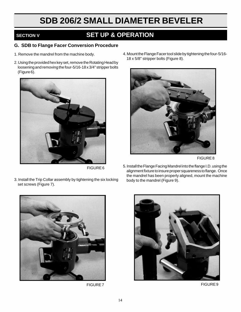
G. SDB to Flange Facer Conversion Procedure
1. Remove the mandrel from the machine body.
2. Using the provided hex key set, remove the Rotating Head byloosening and removing the four-5/16-18 x 3/4" stripper bolts(Figure 6).
3. Install the Trip Collar assembly by tightening the six lockingset screws (Figure 7).
4. Mount the Flange Facer tool slide by tightening the four-5/16-18 x 5/8" stripper bolts (Figure 8).
5. Install the Flange Facing Mandrel into the flange I.D. using thealignment fixture to insure proper squareness to flange. Oncethe mandrel has been properly aligned, mount the machinebody to the mandrel (Figure 9).

SDB 206/2 SMALL DIAMETER BEVELER
15
SECTION V SET UP & OPERATION
H. FLANGE FACING CONVERSIONSetup & Operation
1.Measure the flange I.D. Refer to mandrel leg extension chart( See page 13 ) To select the mandrel adaptor and leg Setrequired to mount in flange I.D.
2.Insert the solid leg set # 56-135-12 in the mandrel head POINTSIDE DOWN ( Figure 10 )
3.Mount the selected adapter over the mandrel head and securewith 3 7/16-20x1-1/2 SHCS (Figure 11)
4.Select extension leg set required. Refer to the I.D. rangechart decal provided on the leg extension box, or on pagein this manual ( Figure 12).
5.Install the adjustment screw into the adjustable leg andtighten completely. (Figure 13)
ABOUT THE ADJUSTABLE LEG An adjustable leg has been provided to compensate for
centering on slip over flanges or butt welded flanges whenmandrel leg placement must be inside the pipe I.D.
NOTE: 56-135-12 solid leg set is required wheninstalling the 56-144-00 adapter cone onto themandrel head.
FIGURE 11
FIGURE 12
FIGURE 13
FIGURE 10

SDB 206/2 SMALL DIAMETER BEVELER
16
6. Insert the leg set into the adapter. (Figure 14)
7. Place the mandrel assembly into the flange I.D. withone leg at the 6 o'clock position. The legs should be kept asclose as possible to the flange I.D. edge, yet back far enoughto perform the desired operation. Snug the mandrel into placeby tightening the draw bar nut with the supplied 1-1/8" wrench(Figure 15).
8.Slide the flange alignment fixture over the mandrel shaft.(Figure 16)
9.Extend the alignment arms, if necessary, with the suppliedhex key set. (Figure 17)
10.Loosen the mandrel assembly using the draw bar nut andpush the alignment fixture firmly against the flange face.Retighten the draw bar nut with the supplied 1-1/8" wrench.(Figure 18) Remove alignment fixture.
SECTION V SET UP & OPERATION
FIGURE 14
FIGURE 15
NOTE: Observe the mandrel keyway slots. Whenthe slots are at the nine o'clock and three o'clockposition the flange facer motor position can beplaced at the six o'clock or twelve o'clock location.Position the mandrel slots at the desired location forair motor clearance or operation.
FIGURE 16
FIGURE 17

SDB 206/2 SMALL DIAMETER BEVELER
17
11.Install the flange facing machine on the mandrel shaft. Besure to wipe the mandrel clean.
Engage the internal machine keys on the mandrel keywayslots. Push the machine forward. Rotate the handle assemblyclockwise, engaging the machine feed nut into the threadedportion of the mandrel shaft. (Figure 19)
12.Install the tooling in to the flange facer tool slide slot. (Figure20). Refer to the tool holder/tool bit diagram.
13.Tighten the tool bit locking set screws with the supplied hexkey set. (Figure 21)
14.Attach the air supply. Press the air motor lever and rotate themachine slowly, to verify clearance. (Figure 22)
SECTION V SET UP & OPERATION
NOTE: The alignment fixture automatically squaresthe mandrel to the flange surface, and assuresprecise square cut.
FIGURE 18
NOTE: Align the internal machine keys with themandrel keyway slots.
FIGURE 19
FIGURE 20
FIGURE 21
IMPORTANT: E.H. Wachs Co. recommendsthe use of an ATM air treatment module (pn 26-407-00) to filter air and lubricate the air motor.The air motor warranty will be void if an ATM isnot used .

SDB 206/2 SMALL DIAMETER BEVELER
18
15.Set the throttle control valve. The FF 313 is equipped witha throttle control valve to meter the air flow to the motor.Rotating the throttle clockwise will open the valve, counterclockwise rotation will close the valve. (Figure 23)
16.Rotate the starwheel nut with the supplied 3/4" socket andratchet, (Figure 24) until the tool bit tip is flush with thedesired surface to be faced. (Figure 25). 17.Rotate the axial feed handle assembly clockwise until the
tool bit just touches the desired surface to be faced.
18.Again rotate the tool slide starwheel nut, raising the bit justabove the surface to be faced.
SECTION V SET UP & OPERATION
FIGURE 22
FIGURE 23
FIGURE 24
FIGURE 25
NOTE: Adjust the cutting head RPM with thethrottle control for flange size being machined. 3 to4 RPM recommended for 10" to 13" flange O.D.Increase RPM as flange sizes become smaller.
SDB 206/2 SMALL DIAMETER BEVELER
19
SECTION V SET UP & OPERATION
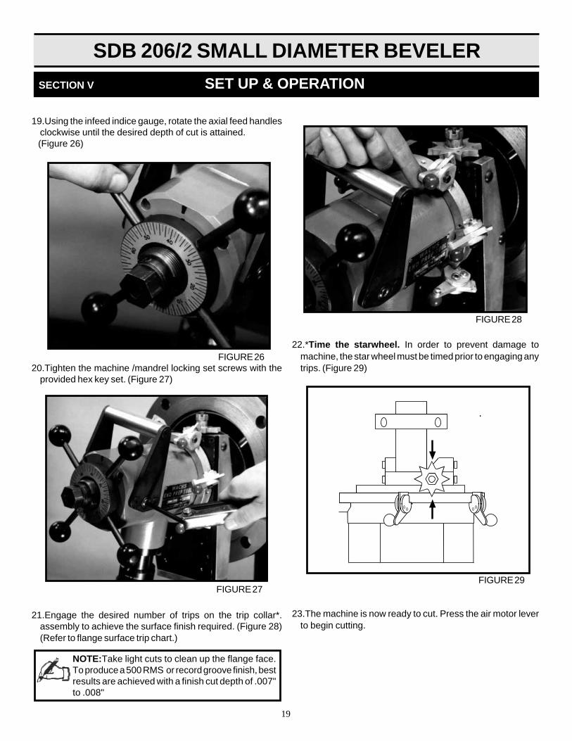
19.Using the infeed indice gauge, rotate the axial feed handlesclockwise until the desired depth of cut is attained.
(Figure 26)
20.Tighten the machine /mandrel locking set screws with theprovided hex key set. (Figure 27)
21.Engage the desired number of trips on the trip collar*.assembly to achieve the surface finish required. (Figure 28)(Refer to flange surface trip chart.)
FIGURE 26
FIGURE 27
NOTE:Take light cuts to clean up the flange face.To produce a 500 RMS or record groove finish, bestresults are achieved with a finish cut depth of .007"to .008"
22.*Time the starwheel. In order to prevent damage tomachine, the star wheel must be timed prior to engaging anytrips. (Figure 29)
23.The machine is now ready to cut. Press the air motor leverto begin cutting.
FIGURE 28
FIGURE 29

SDB 206/2 SMALL DIAMETER BEVELER
20
Tips For a Good FinishSingle Point Flange Facing/Beveling Module
1.Always place mandrel as close to pipe end as possible.
2.Use cutting coolant generously. This will also increasecutter life.
3.CHATTER: Tool chatter occurs when the tool beginsto vibrate during cut. Excessive tool chatter can causepoor quality surface finishes. Chatter can be causedby any one of a number of variables inherent in aportable machine of this type.
4.INTERMITTENT CUTS: When working on a rough cutend of a piece of pipe or a warped flange, tou will needto do an intermittened cut. In order to prolong tool lifeand reduce shock loads on the machine and inserts,intermittent cuts should be performed at a slower feedrate. Once a full cut is achieved, operating speeds canbe increased to normal.
5.As you finish a pass, note your location on the indicedaxial feed gauge. Take your next pass; rotate the feedhandle backwards one full turn to your noted locationand retract your tool slide. Once retracted, rotate thefeed handle in the amount you wish for the cut depth ofyour next pass. This will allow you to retract the slidewithout damaging the tooling, remove all backlash inthe feed handle and give you an exact depth of cut onyour next pass.
6.To produce a 500 RMS or record groove finish, the bestresults are achieved with a finish cut depth of .007" to.008".
SECTION V SET UP & OPERATION
Manual Bevel GenerationUsing Single Point Module:
A bevel can be generated with the Flange FacingModule by feeding the cutting tool into the work radiallyand axially simultaneously. As the radial feed ad-vances the tool automatically, the operator must with-draw the tool by rotating the axial feed handle counter-clockwise. The correct amount of axial feed permachine revolution is given on the following chart.
For example, to generate a 30 degree bevel with6 trips engaged (the fastest tool setting), the operatormust withdraw the cutting tool .018" (18 thousanths)increments on the calibrated feed dial located on theFeed Handle Assembly.
TRIP ENGAGEMENT RMS FINISH
1 TRIP 63 RMS
2 TRIP 125 RMS
4 TRIP 250 RMS
6 TRIP 500 RMS
MANUAL BEVEL GENERATION CHART
Trips Axial feed rate required per machine revolution
Engaged 10º Bevel 20º Bevel 30º Bevel 37.5º Bevel
6 .006" .011" .018" .024"
4 .004" .008" .012" .016"
2 .002" .004" .006" .008"
1 .001" .002" .003" .004"

SDB 206/2 SMALL DIAMETER BEVELER
21
MAINTENANCE
SECTION VI

SDB 206/2 SMALL DIAMETER BEVELER
22
Under normal operating conditions, the bevel gear sets androller bearing should be inspected every 100 hours of operationand lubricated as needed. If exceptionally difficult work hasbeen performed or if excessive coolant has contaminated thegear sets and roller bearings, inspection should be done muchmore frequently.
The bore of the cutting head, feed nut and mandrelmust be kept cleaned and oiled
MAIN SHAFT BEARING PRE-LOAD
Lock Nut Tool Required
After the first ten hours of operation, the mainshaft bearingpreload should be checked. Remove the air motor. Removethe 4 1/4-20 x2 1/2 SHCS to remove feed nut housing (56-002-00). Bend the lock washer (56-034-00) tab clear from thelocknut (56-033-00). Insert and tighten an old, used tool bit intoone of the slots on the cutting head. Clamp machine into abench vise. Using the lock nut tool and a torque wrench, tightenlocknut to 50 ft. lbs. while rotating the main housing. Oncetight, secure lock washer tang into the closest locknut slot.Replace feed nut housing and fasteners, replace and secureair motor.
After every ten hours of operations, inspect the mandrel guidebushing for wear. Replace as necessary.
NOTE: Excessive chatter may indicate a worn mandrelguide Bushing.
After 40 hours of operation, flush the air motor with a solutionof three parts cleaning solvent and one part air motor oil. Afterflushing, add 1 oz. (30 cc)air motor oil into air line and run airmotor for one minute. It is very important that the componentsof the mandrel assembly remain clean and free from corrosion.The legs and machine surfaces should be cleaned and oiled ona daily basis.
SECTION VI MAINTENANCE
MANDREL STRESS INSPECTION PROCEDURE:
1. The mandrel should be removed from the machine bodyand inspected after every twenty hours of operation.
2. Remove the drawbar nut (# 56-025-00) and the collar nut (#56-024-00).
3. Remove the mandrel from the machine body by rotating thefeed handles counter clockwise.
4. Physically examine the mandrel and threads, look for anysigns of wear or damage.
5. Measure the length of the threaded drawbar. If the drawbarlength is 18", the drawbar may remain in use. If the length ofthe drawbar is equal to or exceeds 18-1/2" in length thedrawbar is no longer safe and should be replaced.

SDB 206/2 SMALL DIAMETER BEVELER
23
MISCELLANEOUSCHARTS
ANDGRAPHS
SECTION VII
SDB 206/2 SMALL DIAMETER BEVELER
24
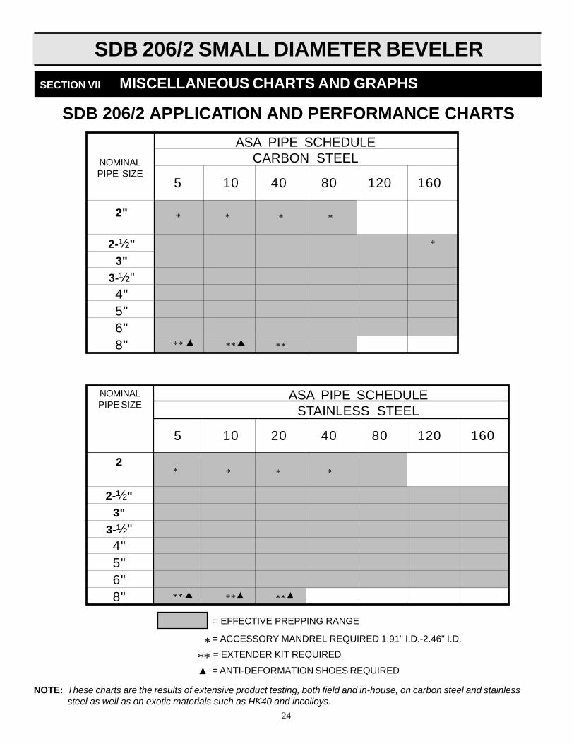
SDB 206/2 APPLICATION AND PERFORMANCE CHARTS
5 10 40 80 120 160
ASA PIPE SCHEDULECARBON STEELNOMINAL
PIPE SIZE
2"
2-½"
3"
3-½"4"5"6"8"
5 10 20 40 80 120 160
ASA PIPE SCHEDULESTAINLESS STEEL
NOMINALPIPE SIZE
2
2-½"
3"
3-½"4"5"6"8"
= EFFECTIVE PREPPING RANGE
** **
NOTE: These charts are the results of extensive product testing, both field and in-house, on carbon steel and stainlesssteel as well as on exotic materials such as HK40 and incolloys.
SECTION VII MISCELLANEOUS CHARTS AND GRAPHS
**
** ** **
* * * *
*
* * * *
*** = EXTENDER KIT REQUIRED
= ACCESSORY MANDREL REQUIRED 1.91" I.D.-2.46" I.D.
= ANTI-DEFORMATION SHOES REQUIRED

SDB 206/2 SMALL DIAMETER BEVELER
25
ORIGINAL DESCRIPTION REPLACEMENT REPLACEMENT TOOL INSERTSPART No. TOOL HOLDER STANDARD J PREP
HSS CARBIDE HSS CARBIDE
56-701-01 Facing-Low Range** 56-708-01
56-701-02 Facing-High Range** 56-708-02 N/A N/A
56-703-00 20º J-Beveling 56-709-01
56-704-00 20º J-Beveling 56-709-05
56-706-00 30º Beveling 56-709-02 56-711-01 56-712-01 56-711-02 56-712-02
56-700-01 37.5º Beveling 56-709-03
56-700-02 37.5º Beveling 56-709-03
SECTION VII MISCELLANEOUS CHARTS AND GRAPHS
SDB 206/2 TOOLING CONVERSION CHART
INSERT BEVELING HOLDERS ARE DESIGNED FOR USE WITH EITHER LOW RANGE OR HIGH RANGE FACING TOOLS ON ALL APPLICATIONS.LOW RANGE FACING HOLDER #56-708-01-HEIGHT: 1.25"HIGH RANGE FACING HOLDER #56-708-02-HEIGHT: 1.50"
NAME PART No. RANGE
Low Range Tool Holder 56-195-00 3.00: through 10.0"
High Range Tool Holder 56-194-00 6.00: through 13.0"
Tool Holder Tool Bit 56-710-00 N/A
FLANGE FACING MODULE TOOLHOLDER/TOOL BIT DIAGRAM

SDB 206/2 SMALL DIAMETER BEVELER
26
PartDescription Number Comments
10º ID Deburring 56-702-01
10º ID Deburring 56-702-02
10º ID Deburring 56-702-03
Small 4:1 Taper 56-705-01Counterbore
Med. 4:1 Taper 56-705-02Counterbore
Large 4:1 Taper 56-705-03Counterbore
20º J-Bevel 56-709-01
Tooling Holder
20º J-Bevel H.R. 56-709-05Tooling Holder
30ºBevel 56-709-02
Tooling Holder
37.5ºBevel 56-709-03Tooling Holder
Low range 56-708-01 2.06"(52mm) minimum I.D.
Facing Holder to 5.24"(133mm) maximum I.D.
High Range 56-708-02 3.04"(77mm) minimum I.D.
Facing Holder to 5.24"(133mm) maximum I.D.
HSS or Carbide 56-711-01(HSS)Face/Bevel Insert 56-712-01(C)
HSS or Carbide 56-711-02(HSS)J prep Insert 56-712-02(C)
SDB 206/2TOOLING SELECTION CHART
NOTE: Tool holder assembly includes: (1) Steel Holder, (2) Insert Screws and (1) Allen Wrench. Please call for currentpricing on tooling and inserts. Tool bit ranges listed are to be used as guides when performing simultaneous
prepping.Individual tool usage will expand the cutting range.

SDB 206/2 SMALL DIAMETER BEVELER
27
SECTION VII MISCELLANEOUS CHARTS AND GRAPHS
COMBINATION TOOLING SELECTION CHART
Facing Beveling Deburring Minimum I.D. Maximum I.D.
56-708-01 56-709-03 56-702-01 2.28"(57.9mm) 5.13"(130.3mm)
56-708-02 56-709-03 56-702-03 3.25"(82.5mm) 6.13"(155.7mm)
STANDARD 7" DIAMETER ROTATING HEADSIMULTANEOUS 3-TOOL-FACE, BEVEL, DEBURR (For 1/16 (+or-) 1/32 Land Generation)
Facing Beveling Deburring Minimum I.D. Maximum I.D.
56-708-01 56-709-03 56-702-01 2.28"(57.9mm) 2.90"(73.6mm)
56-708-01 56-709-03 56-702-02 2.65"(67.3mm) 6.13"(85.3mm)
56-708-02 56-709-03 56-702-03 3.26"(82.8mm) 3.88"(98.5mm)
56-708-02 56-709-03 56-702-03 3.63"(92.2mm) 4.34"(110.2mm)
OPTIONAL 4.5" DIAMETER SMALL ROTATING HEADSIMULTANEOUS 3-TOOLFACE, BEVEL, DEBURR (For 1/16(+or-)1/32 LandGeneration)
Tool # Minimum I.D. Maximum I.D. Minimum I.D. Maximum I.D.
56-705-01 2.75"(69.8mm) 5.50"(139.7mm) 2.75"(69.8mm) 3.88"(98.5mm)
56-705-02 3.88"(98.5mm) 6.63"(168.4mm) 3.88"(98.5mm) 4.63"(117.6mm)
56-705-03 4.88"(123.9mm) 7.63"(193.8mm)
COUNTERBORE TOOLINGTOOLS FOR 14º x1/2" DP. COUNTERBORE WHEN USED WITH 56-701 FACING BIT

SDB 206/2 SMALL DIAMETER BEVELER
28
SECTION VII MISCELLANEOUS CHARTS AND GRAPHS
PART # SCREW # I.D. RANGE
NONE NONE 2.28 - 2.84
56-023-01 90-043-03 2.66 - 3.23
56-023-02 90-043-05 3.03 - 3.60
56-023-03 90-043-07 3.40 - 3.97
56-023-04 90-043-08 3.77 - 4.34
56-023-05 90-043-11 4.15 - 4.72
56-023-06 90-043-12 4.52 - 5.09
56-023-07 90-043-15 4.89 - 5.46
56-023-08 90-043-17 5.27 - 5.84
56-023-09 90-043-20 5.64 - 6.21
56-023-10 90-043-20 6.01 - 6.58
*56-023-11* 90-043-22 7.63 - 8.20
** SPECIAL ORDER - NOT INCLUDED WITH MACHINE
REPLACES OBSOLETE STANDARD MANDRELAS OF 13 FEB 1995
STANDARD MANDRELLEG EXTENSION CHART
STANDARD MANDREL 56-401-01

SDB 206/2 SMALL DIAMETER BEVELER
29
PART # SCREW # I.D. RANGE
NONE NONE 2.28 - 2.84
56-023-01 90-043-03 2.67 - 3.23
56-023-02 90-043-05 3.04 - 3.60
56-023-03 90-043-07 3.41 - 3.97
56-023-04 90-043-08 3.78 - 4.34
56-023-05 90-043-11 -----------
56-023-06* 90-043-20
STANDARD MANDREL 56-409-01 REPLACED BY STANDARD MANDREL 56-401-01 13 FEB. 95
OBSOLETESTANDARD MANDREL
LEG EXTENSION CHART
* SPECIAL ORDER - NOT INCLUDED WITH MACHINE
PART # SCREW # I.D. RANGE
NONE NONE 3.80-4.58
56-023-01 90-043-03 4.28-4.96
56-023-02 90-043-05 4.65-5.34
56-023-03 90-043-07 5.02-5.71
56-023-04 90-043-08 5.40-6.08
56-023-05 90-043-11 5.77-6.46
56-023-06* 90-043-20 7.77-8.45
* SPECIAL ORDER - NOT INCLUDED WITH MACHINE

SDB 206/2 SMALL DIAMETER BEVELER
30
**NOTE: Solid legs (#56-135-12) Mmust be inserted into mandrel (#56-414-01) prior to attaching part no. 56-144-00 Mandrel Adapter.MANDREL ADAPTER WILL NOT FUNCTION IF THE THREE SOLID LEGS ARE NOT IN THE MANDREL BODY.
FLANGE FACING MANDRELLEG EXTENSION CHART
ASSEMBLY #
#56-414-01mandrel - no adapter.(3.00" - 6.08" range)
#56-414-00 mandrel - #56-144-00mandrel adapter
( 6.0"- 10.0" range)
SOLID LEG (2 PCS.) ADJ. LEG (1 PC. ) CHUCKING RANGE/LEG SETPART # LENGTH. PART # LENGTH MIN.DIA. MAX DIA.
56-135-12** 1.250 use 3 solid legs ----------- 3.00 3.4856-135-04 1.350 56-136-04 1.150 3.20 3.6856-135-05 1.550 56-136-05 1.350 3.60 4.0856-135-06 1.750 56-136-06 1.550 4.00 4.4856-135-07 1.950 56-136-07 1.750 4.40 4.8856-135-08 2.150 56-136-08 1.950 4.80 5.2856-135-09 2.350 56-136-09 2.150 5.20 5.6856-135-10 2.550 56-136-10 2.350 5.60 6.0856-145-01 1.500 56-146-01 1.300 6.00 6.4856-145-02 1.700 56-146-02 1.500 6.40 6.8856-145-03 1.900 56-146-03 1.700 6.80 7.2856-145-04 2.100 56-146-04 1.900 7.20 7.6856-145-05 2.300 56-146-05 2.100 7.60 8.0856-145-06 2.500 56-146-06 2.300 8.00 8.4856-145-07 2.700 56-146-07 2.500 8.40 8.8856-145-08 2.900 56-146-08 2.700 8.80 9.2856-145-09 3.100 56-146-09 2.900 9.20 9.6856-145-10 3.300 56-146-10 3.100 9.60 10.08
MACHINE ROTATING HEAD SIZE FACING HOLDER MINIMUM I.D. MAXIMUM I.D.SDB 206/2 1-7/8"thru 4-1/2" (56-004-00) LOW RANGE 56-708-01 2.06" (52mm) 2.68" (68mm)
HIGH RANGE 56-708-02 2.75" (70mm) 3.43" (87mm)
1-7/8"thru7" (56-005-00) LOW RANGE 56-708-01 2.06" (52mm) 5.24" (133mm)HIGH RANGE 56-708-02 3.04" (77mm) 6.21" (157mm)
NOTE: INSERT BEVELING HOLDERS ARE DESIGNED FOR USE WITH EITHER LOW RANGE OR HIGH RANGE FACING TOOLS ON ALL APPLICATIONS.
LOW RANGE FACING HOLDER #56-708-01- HEIGHT: 1.25"HIGH RANGE FACING HOLDER #56-708-02 HEIGHT: 1.50"
LOW/HIGH RANGE FACING HOLDER USAGE CHART

SDB 206/2 SMALL DIAMETER BEVELER
31
SECTION VIII
PARTS LISTSAND
EXPLODED VIEWDRAWINGS

SDB 206/2 SMALL DIAMETER BEVELER
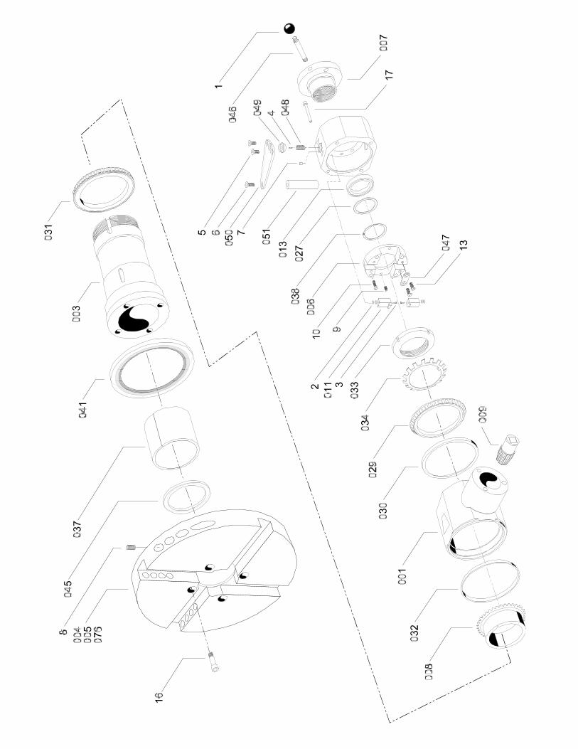
32
REF. NO. PART NO. QUANTITY DESCRIPTIONN/S 26-047-00 1 Plate, name001 56-001-00 1 Body, main002 56-180-00 1 Housing, feed nut003 56-003-00 1 Shaft, main004 56-004-00 1 Head, Rotating (small)*005 56-005-00 1 Head, Rotating (standard)076 56-076-00* 1 Head, Rotating (large)*006 56-181-00 1 Collar, key007 56-007-00 1 Nut, feed008 56-008-00 1 Gear, ring009 56-009-00 1 Gear, pinion011 56-182-00 2 Key, mandrel013 56-013-00 1 Bearing, feed nut027 56-027-00 1 Washer029 56-029-00 1 Cone030 56-030-00 1 Cup031 56-031-00 1 Cone032 56-032-00 1 Cup033 56-033-00 1 Locknut034 56-034-00 1 Lockwasher037 56-037-00 1 Bushing038 56-038-10 1 Snap ring041 56-041-00 1 Seal043 56-043-00 1 Wiper, feltN/S 56-150-00 1 Case, storage046 56-053-00 4 Stud, 3/8-16 lg.047 56-183-00 2 Strap048 56-184-00 2 Screw, key adjust.049 56-185-00 2 Bushing, adjustment screw050 56-186-00 2 Bracket, handle051 56-187-00 1 Handle, liftingN/S 56-189-00 1 Label, feed ringN/S 66-147-00 1 Label, warning
FASTENERS:1 90-900-50 4 Knob, black 3/8-16 x 1-3/8"2 66-140-00 4 Washer, spring (N/S)3 90-040-55 2 SHCS, 10-32 x 1/24 90-044-51 2 SSS, 10-32 x 3/16 ft. pt.5 90-063-07 4 FHCS, 5/16-18 x 3/4"6 90-063-10 2 FHCS, 5/16-18 x 1"7 90-046-02 2 Pin , dowel, 3/16 x 1/48 90-074-17 16 SSS, 3/8-16x3/49 90-046-07 2 Pin, dowel 3/16" x 3/4"
10 90-050-15 4 SHCS, 1/4-20 x 1-1/2"13 90-053-06 4 FHCS, 1/4-20 x 5/814 90-057-10 1 key, 1/4 sq. x 1"16 90-067-59 4 Bolt, Stripper, 5/16 x 1"17 90-050-25 4 SHCS, 1/4-20 x 2-1/2N/S 90-800-06 1 Key, hex set 5/64-1/4"N/S 90-800-29 1 wrench, combo 1-1/8"N/S 90-800-62 1 wrench ,allen 3/16 "T" 9"
SDB 206/2 BEVELING MACHINE ASSEMBLYPART NO. 56-000-01 pneumatic
56-000-02 electric 56-000-03 hydraulic
*Part sold separately. Please contact your nearest Wachs representative for pricing and availability.

SDB 206/2 SMALL DIAMETER BEVELER
34
REF PART NO. QUANTITY DESCRIPTION
010 56-010-00 1 Ring, Spacer039 56-039-00 1 Snap Ring040 56-040-00 1 Bearing044 56-044-01 1 Motor, Air
FASTENERS:
10 90-098-65 1 Elbow, Male 1/2 HP11 66-100-00 1 Valve, Speed Control18 90-060-12 3 SHCS, 5/16-18 x 1-1/4
SDB 206/2 PNEUMATIC DRIVE ASSEMBLY56-000-01


SDB 206/2 SMALL DIAMETER BEVELER
36
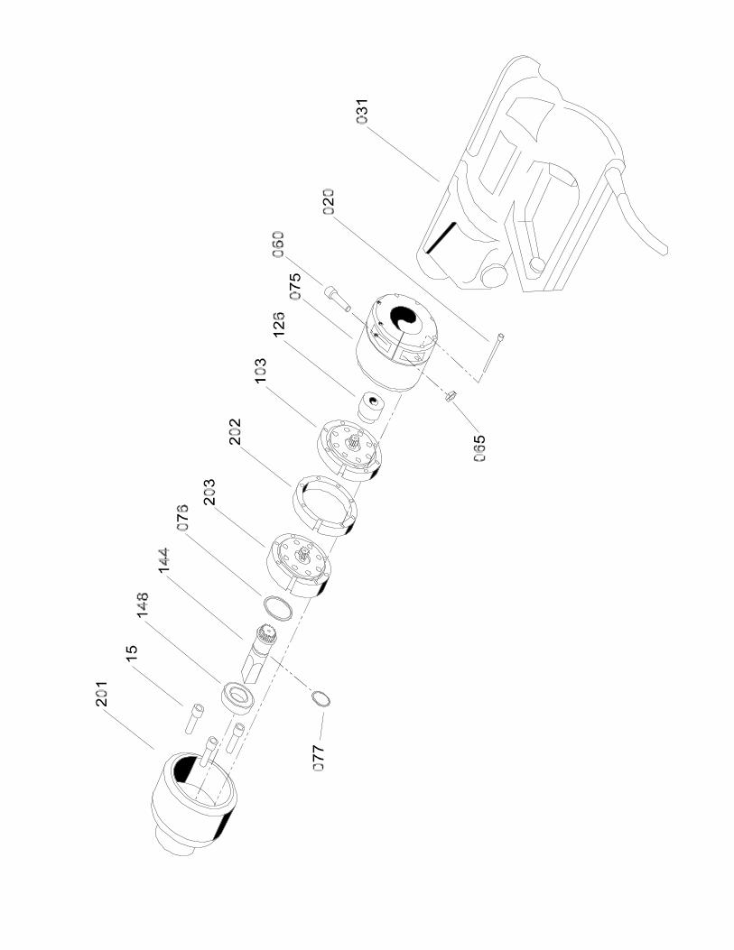
SDB 206/2 ELECTRIC DRIVE ASSEMBLY
REF PART NO. QUANTITY DESCRIPTION
103 11-103-00 1 GEAR, PLANETARY*075 16-075-00 1 HOUSING, REAR076 16-076-00 1 RING, RETAINING077 16-077-00 1 RING, RETAINING126 26-126-00 1 WLDMNT, INPUT SHAFT031 30-031-00 1 MOTOR 110 VAC201 56-201-00 1 HOUSING, GEAR202 56-202-00 1 SPACER, GEARSET203 56-203-00 1 GEAR, PLANETARY144 66-144-00 1 COUPLING, DRIVE148 66-148-00 1 BEARING020 90-020-25 7 SHCS,8-32 x 2-1/2060 90-060-12 1 SHCS,5/16-18 X 1 1/4065 90-065-01 1 NUT,HEX 5/16-1815 90- 3 SHCS

SDB 206/2 SMALL DIAMETER BEVELER
38
SDB 206/2 HYDRAULIC DRIVE ASSEMBLY PART NO. 56-413-00
REF PART NO. QUANTITY DESCRIPTION
132 1 56-132-00 SPACER182 1 53-073-00 HYDRAULIC MOTOR183 1 02-203-00 HYDRAULIC MOTOR COUPLING184 1 56-200-00 MOTOR COUPLING KEY185 1 05-092-00 HYDRAULIC MOTOR ADAPTER187 1 23-187-00 MANIFOLD188 1 23-188-00 FLOW VALVE189 1 23-189-00 COMPENSATOR SPOOL192 2 05-150-00 "O" RING
FASTENERS
186 3 90-060-08 5/16-18x7/8 SHCS190 4 90-061-25 5/16-18x2-1/2 HHCS191 4 90-055-53 1/4 FLAT WASHER193 1 90-098-58 1/2 HEX NIPPLE HP194 2 90-090-12 1/2-13x1-1/4 SHCS195 1 90-054-04 1/4-20x3/4 SSS247 1 90-098-65 1/2 MALE ELBOW


SDB 206/2 SMALL DIAMETER BEVELER
40
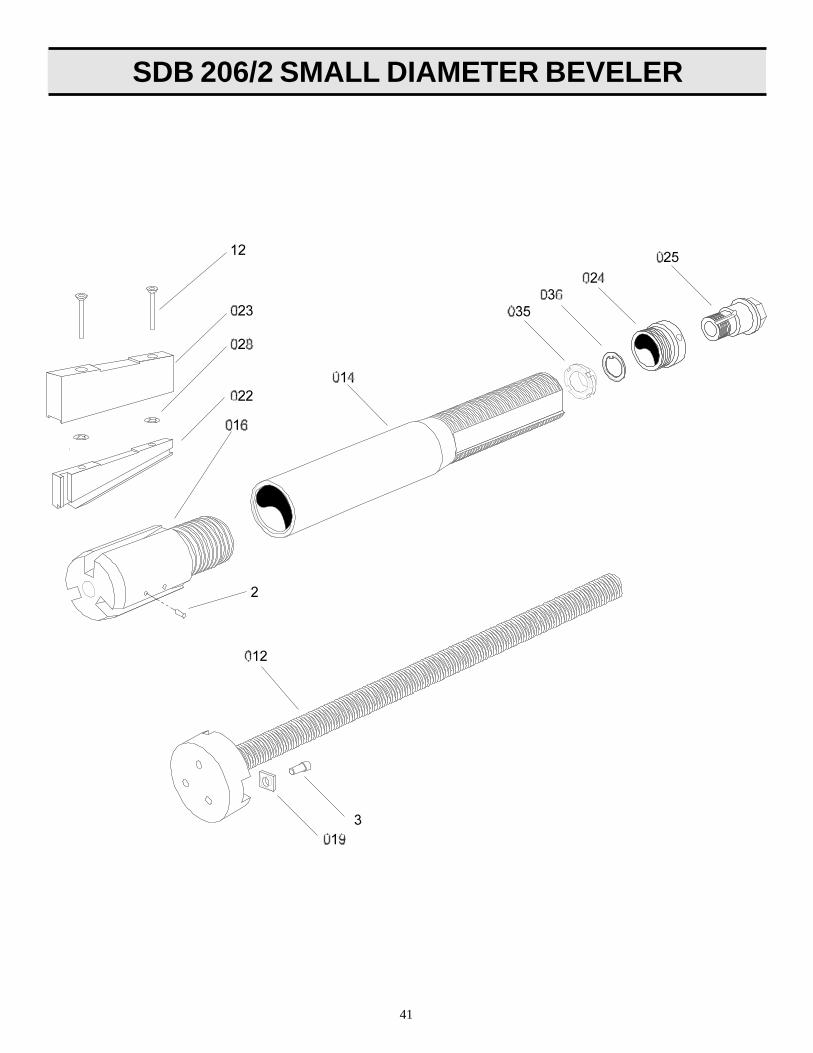
SDB 206/2 STANDARD MANDREL(2.270"-6.580" I.D.) 56-401-01
REF PART # QTY DESCRIPTION
012 56-042-00 1 DRAWPLATE014 56-188-00 1 MANDREL016 56-015-00 1 BODY, CHUCK STANDARD019 56-019-00 3 TAB, LOCKING022 56-021-00 3 LEG, CHUCK023 56-023-01 3 EXT. LEG 2.66-3.23023 56-023-02 3 EXT. LEG 3.03-3.60023 56-023-03 3 EXT. LEG 3.40-3.97023 56-023-04 3 EXT. LEG 3.77-4.34023 56-023-05 3 EXT. LEG 4.15-4.72023 56-023-06 3 EXT. LEG 4.52-5.09023 56-023-07 3 EXT. LEG 4.89-5.46023 56-023-08 3 EXT. LEG 5.27-5.84023 56-023-09 3 EXT. LEG 5.64-6.21023 56-023-10 3 EXT. LEG 6.01-6.58024 56-024-02 1 COLLAR, DRAW BAR NUT025 56-025-00 1 NUT, DRAW BAR028 56-028-00 30 PUSH, WASHER035 56-035-00 1 LOCK NUT036 56-036-00 1 WASHER, TONGUED
FASTENERS2 90-026-55 6 ROLL PIN, 1/8" X 1/2"3 90-039-05 3 LHCS 10-24 X 1-1/4"12 90-043-03 6 FHCS, 10-24 x 3/8"
90-043-06 6 FHCS, 10-24 x 5/8"90-043-07 6 FHCS, 10-24 x 3/4"90-043-10 6 FHCS, 10-24 x 1"90-043-11 6 FHCS, 10-24 x 1-1/8"90-043-12 6 FHCS, 10-24 X 1-1/4"90-043-15 6 FHCS, 10-24 x 1-1/2"90-043-17 6 FHCS, 10-24 x 1-3/4"90-043-20 6 FHCS, 10-24 x 2"90-043-22 6 FHCS, 10-24 x 2-1/4"
* REPLACES OBSOLETE STANDARD MANDREL AS OF 13 FEB. 95
SDB 206/2 SMALL MANDREL(1.91"-2.46" I.D.) 56-402-01
REF PART # QTY DESCRIPTION
012 56-052-00 1 DRAWPLATE, 2"014 56-188-00 1 MANDREL016 56-047-00 1 BODY, CHUCK 2"019 56-019-00 3 TAB, LOCKING022 56-048-00 3 LEG, CHUCK 2"024 56-024-02 1 COLLAR, DRAW BAR NUT025 56-025-00 1 NUT, DRAW BAR035 56-035-00 1 LOCK NUT036 56-036-00 1 WASHER, TONGUED
FASTENERS
2 90-026-55 6 ROLL PIN, 1/8" X 1/2"3 90-039-05 3 LHCS 10-24 X 1-1/4"
* REPLACES OBSOLETE STANDARD MANDREL AS OF 13 FEB. 95
SDB 206 CAPTIVATED LEG MANDREL BILL OF MATERIALS
SDB 206/2 SMALL DIAMETER BEVELER
41

SDB 206/2 SMALL DIAMETER BEVELER
42
SDB 206/2 Extension Adapter Hub(for 6"-10.10" I.D.) 56-415-00
REF PART # QTY DESCRIPTION
137 56-137-00 2 SCREW, ADJUSTABLE144 56-144-00 1 ADAPTER, 3" CHUCK145 56-145-01 2 LEG, 5/8"145 56-145-02 2 LEG, 5/8"145 56-145-03 2 LEG, 5/8"145 56-145-04 2 LEG, 5/8"145 56-145-05 2 LEG, 5/8"145 56-145-06 2 LEG, 5/8"145 56-145-07 2 LEG, 5/8"145 56-145-08 2 LEG, 5/8"145 56-145-09 2 LEG, 5/8"145 56-145-10 2 LEG, 5/8"146 56-146-01 1 LEG, 5/8" ADJ.146 56-146-02 1 LEG, 5/8" ADJ.146 56-146-03 1 LEG, 5/8" ADJ.146 56-146-04 1 LEG, 5/8" ADJ.146 56-146-05 1 LEG, 5/8" ADJ.146 56-146-06 1 LEG, 5/8" ADJ.146 56-146-07 1 LEG, 5/8" ADJ.146 56-146-08 1 LEG, 5/8" ADJ.146 56-146-09 1 LEG, 5/8" ADJ.146 56-146-10 1 LEG, 5/8" ADJ.147 56-147-00 2 SCREW, 5/8"ADJUSTABLE
FASTENERS
2 90-080-15 3 SHCS, 7/16-20 x 1-1/23 90-059-18 3 PLUNGER, BALL
N/S 56-168-00 1 BLOCK, STORAGEN/S 56-169-00 1 LABEL, LEG RANGE
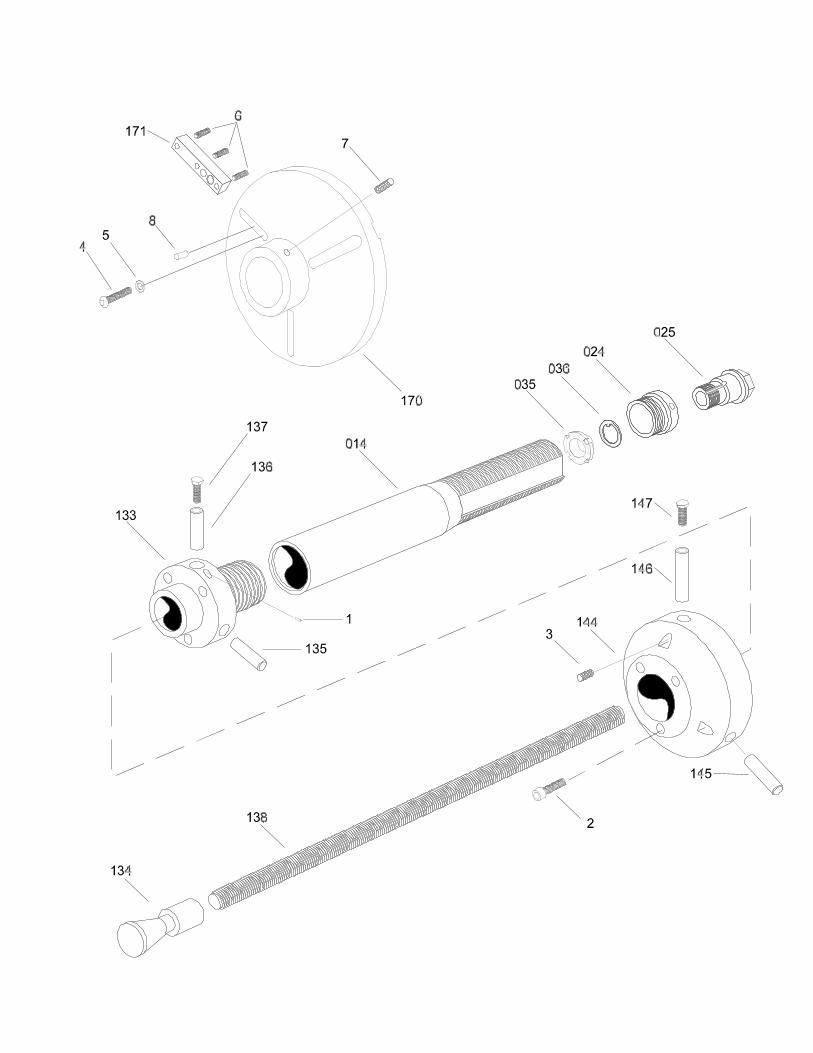
SDB 206/2 3-Jaw Independent "Short Perch" Mandrel(for 2"-3.250" I.D.) 56-414-01
REF PART # QTY DESCRIPTION
014 56-188-00 1 MANDRELN/S 56-166-00 1 BLOCK, STORAGEN/S 56-167-00 1 LABEL, LEG024 56-024-02 1 COLLAR, DRAW BAR NUT025 56-025-00 1 NUT, DRAW BAR035 56-035-00 1 LOCK NUT036 56-036-00 1 WASHER, TOUNGED133 56-143-00 1 BODY, CHUCK, 3"134 56-134-00 1 CONE, DRAW135 56-135-04 2 LEG135 56-135-05 2 LEG135 56-135-06 2 LEG135 56-135-07 2 LEG135 56-135-08 2 LEG135 56-135-09 2 LEG135 56-135-10 2 LEG135 56-135-12 3 LEG136 56-136-04 1 LEG, ADJUSTABLE136 56-136-05 1 LEG, ADJUSTABLE136 56-136-06 1 LEG, ADJUSTABLE136 56-136-07 1 LEG, ADJUSTABLE136 56-136-08 1 LEG, ADJUSTABLE136 56-136-09 1 LEG, ADJUSTABLE136 56-136-10 1 LEG, ADJUSTABLE137 56-137-00 2 SCREW, ADJUSTABLE138 56-138-00 1 BAR, DRAW170 56-170-00 1 BODY, FIXTURE171 56-171-00 3 LEG
FASTENERS
1 90-049-11 3 PLUNGER, BALL4 90-052-08 3 BHCS, 1/4-20 x 7/8"5 90-055-56 3 WASHER, #126 90-044-03 9 SSS, 10-24 x 3/8"7 90-059-29 2 SSS BRS. TP 1/4-20 x 5/8"8 90-056-05 3 PIN, DOWEL 1/4 x 1/2"
SDB 206/2 3-JAW INDEPENDENT "SHORT PERCH"BILL OF MATERIALS

SDB 206/2 SMALL DIAMETER BEVELER
44
REF PART # QTY DESCRIPTION
014 56-188-00 1 MANDREL022 56-048-00 3 LEG, CHUCK 2"024 56-024-02 1 COLLAR, DRAW BAR NUT025 56-025-00 1 NUT, DRAW BAR035 56-035-00 1 LOCK NUT036 56-036-00 1 WASHER, TONGUED037 56-133-00 1 BODY, CHUCK038 56-134-00 1 CONE, DRAW133 56-133-00 1 BODY, CHUCK135 56-135-01 3 LEG135 56-135-02 3 LEG135 56-135-03 2 LEG136 56-136-03 1 LEG, ADJUSTABLE137 56-137-00 1 LEG, ADJUSTABLE139 56-139-00 1 GAUGE, ALIGNMENTN/S 56-141-00 1 LABEL, LEG RANGE
FASTENERS
1 90-049-11 3 PLUNGER, BALL2 90-059-04 2 THUMB SCRW, 1/4-20 x 1-1/4


SDB 206/2 SMALL DIAMETER BEVELER
46
SDB 206 MANDREL - STANDARD*
REF PART # QTY DESCRIPTION
012 56-012-00 1 DRAW BAR, LARGE014 56-188-00 1 MANDREL016 56-016--00 1 BODY, CHUCK-LARGE019 56-019-00 3 TAB, LOCKING022 56-022-00 3 LEG, CHUCK-LARGE023 56-023-01 3 EXTENSION, LEG 0.250023 56-023-02 3 EXTENSION, LEG 0.437023 56-023-03 3 EXTENSION, LEG 0.625023 56-023-04 3 EXTENSION, LEG 0.812023 56-023-05 3 EXTENSION, LEG 1.000023 56-023-06 3 EXTENSION, LEG 2.000024 56-024-00 1 COLLAR DRAW BAR NUT025 56-025-00 1 NUT, DRAW BAR028 56-028-00 30 PUSH WASHER035 56-035-00 1 LOCK NUT036 56-036-00 1 WASHER, TOUNGED
FASTENERS
2 90-026-55 6 ROLL PIN 1/8" x 1/2"3 90-039-05 3 LHCS 10-24x1/2"12 90-043-11 6 FHCS 10-24x1-1/4"13 90-043-05 6 FHCS 10-24x1/2"14 90-043-03 6 FHCS 10-24x3/8"15 90-043-08 6 FHCS10-24x7/8"16 90-043-07 6 FHCS 10-24x3/4"
OBSOLETE STANDARD MANDREL(Obsolete as of February, 1995)

SDB 206/2 SMALL DIAMETER BEVELER
47
SDB 206/2 SMALL DIAMETER BEVELER
48
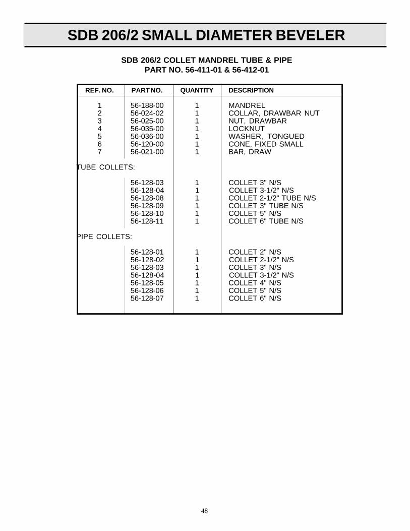
REF. NO. PART NO. QUANTITY DESCRIPTION
1 56-188-00 1 MANDREL2 56-024-02 1 COLLAR, DRAWBAR NUT3 56-025-00 1 NUT, DRAWBAR4 56-035-00 1 LOCKNUT5 56-036-00 1 WASHER, TONGUED6 56-120-00 1 CONE, FIXED SMALL7 56-021-00 1 BAR, DRAW
TUBE COLLETS:
56-128-03 1 COLLET 3" N/S56-128-04 1 COLLET 3-1/2" N/S56-128-08 1 COLLET 2-1/2" TUBE N/S56-128-09 1 COLLET 3" TUBE N/S56-128-10 1 COLLET 5" N/S56-128-11 1 COLLET 6" TUBE N/S
PIPE COLLETS:
56-128-01 1 COLLET 2" N/S56-128-02 1 COLLET 2-1/2" N/S56-128-03 1 COLLET 3" N/S56-128-04 1 COLLET 3-1/2" N/S56-128-05 1 COLLET 4" N/S56-128-06 1 COLLET 5" N/S56-128-07 1 COLLET 6" N/S
SDB 206/2 COLLET MANDREL TUBE & PIPEPART NO. 56-411-01 & 56-412-01


SDB 206/2 SMALL DIAMETER BEVELER
50
REF # PART # QTY DESCRIPTION
105 56-155-00 1 PLATE, BASE106 56-156-00 1 STIFFENER, LEFT107 56-157-00 1 STIFFENER, RIGHT108 56-158-00 1 SUPPORT, BRIDGE109 66-109-00 1 SUPPORT, END110 56-159-00 1 PLATE, SLIDE111 56-160-00 1 BLOCK, FEED SCREW112 56-161-00 1 SCREW, FEED113 56-162-00 1 SLIDE, MALE114 66-114-00 1 WHEEL, STAR015 66-015-00 2 BUSHING, FEED SCREW043 56-043-00 1 WIPER, FELT066 56-066-00 2 GIBN/S 56-194-00 1 TOOL HOLDER H. RANGE*N/S 56-195-00 1 TOOL HOLDER L. RANGE*N/S 56-710-00 1 TOOL INSERT*N/S 56-190-00 2 SCREW, INSERTN/S 56-191-00 2 WRENCH, TOOLING81 66-117-00 6 LEVER, TRIP82 56-163-00 1 TRIP COLLAR86 90-900-62 6 KNOB, 10-32x3/487 52-140-00 6 BALL PLUNGER
FASTENERS
4 66-019-00 1 PLUNGER, SPRING6 90-046-05 14 PIN, 3/16 x 1/2 DOWEL7 90-067-56 4 BOLT, STRPER 5/16 x 5/8"8 90-062-08 4 BHCS, 5/16-18 x 7/8"9 90-026-57 1 PIN, ROLL 1/8 x 3/4
10 90-095-10 1 NUT, HEX SLOTTED 1/2-2013 90-055-04 3 NUT, 1/4-20 JAM14 90-054-07 3 SSS, 1/4-20 x 3/415 90-054-04 5 SSS, 1/4-20 x 3/8 KNR PT.16 90-050-08 6 SHCS, 1/4-20 x 7/819 90-050-06 21 SHCS, 1/4-20 x 5/820 90-019-43 1 KEY, 3/32x3/8 WDRUF21 90-059-56 1 LHCS, 1/4-20x7/8N/S 90-800-71 1 WRENCH 1/8" x 6" "T"N/S 90-800-10 1 WRENCH, 3/8" ARM HEXN/S 90-800-45 1 RATCHETN/S 90-800-58 1 SOCKET, 3/4 x 3/8 DRIVE.84 56-073-00 4 1/4" TOGGLE SCREW85 90-042-04 6 10-32 x 1/2" BHCS86 90-045-02 6 NUT, 10-24 JAM88 90-045-05 6 10-32 HEX NUT89 90-057-55 6 1/4 x 1/2 STRIPPER BOLT
SDB 206 FLANGE FACING CONVERSION KITBILL OF MATERIAL
56-421-00
*Parts not shown in exploded view. Please refer to page 26 for tool insertand tool holder for this attachment.


SDB 206/2 SMALL DIAMETER BEVELER
52
REF # PART # QTY DESCRIPTION
014 56-188-00 1 MANDREL, BODY024 56-024-02 1 COLLAR, DRAW BAR NUT025 56-025-00 1 NUT, DRAW BAR035 56-035-00 1 LOCKNUT036 56-036-00 1 WASHER, TOUNGED133 56-143-00 1 BODY, CHCK 3"134 56-134-00 1 CONE138 56-138-00 1 BAR, DRAW144 56-144-00 1 ADAPTER, 3" CHUCK135 56-135-04 2 LEG135 56-135-05 2 LEG135 56-135-06 2 LEG135 56-135-07 2 LEG135 56-135-08 2 LEG135 56-135-09 2 LEG135 56-135-10 2 LEG135 56-135-12 2 LEG136 56-136-04 1 LEG, ADJUSTABLE136 56-136-05 1 LEG, ADJUSTABLE136 56-136-06 1 LEG, ADJUSTABLE136 56-136-07 1 LEG, ADJUSTABLE136 56-136-08 1 LEG, ADJUSTABLE136 56-136-09 1 LEG, ADJUSTABLE136 56-136-10 1 LEG, ADJUSTABLE137 56-137-00 2 SCREW, ADJUSTABLE145 56-145-01 2 LEG, 5/8"145 56-145-02 2 LEG, 5/8"145 56-145-03 2 LEG, 5/8"145 56-145-04 2 LEG, 5/8"145 56-145-05 2 LEG, 5/8"145 56-145-06 2 LEG, 5/8"145 56-145-07 2 LEG, 5/8"145 56-145-08 2 LEG, 5/8"145 56-145-09 2 LEG, 5/8"145 56-145-10 1 LEG, 5/8" ADJUSTABLE146 56-146-01 1 LEG, 5/8" ADJUSTABLE146 56-146-02 1 LEG, 5/8" ADJUSTABLE146 56-146-03 1 LEG, 5/8" ADJUSTABLE146 56-146-04 1 LEG, 5/8" ADJUSTABLE146 56-146-05 1 LEG, 5/8" ADJUSTABLE146 56-146-06 1 LEG, 5/8" ADJUSTABLE146 56-146-07 1 LEG, 5/8" ADJUSTABLE146 56-146-08 1 LEG, 5/8" ADJUSTABLE146 56-146-09 1 LEG, 5/8" ADJUSTABLE146 56-146-10 1 LEG, 5/8" ADJUSTABLE147 56-147-00 2 SCREW, ADJUSTABLE 5/8"170 56-170-00 1 BODY, FIXTURE171 56-171-00 3 LEG
FASTENERS1 90-049-11 3 PLUNGER, BALL2 90-080-15 3 SHCS, 7/16-20x1-1/2"3 90-059-18 3 PLUNGER, BALL4 90-052-08 3 BHCS, 1/4-20x7/8"5 90-055-56 3 #12 FLAT WASHER6 90-044-03 9 SSS, 10-24x3/8"7 90-059-29 2 SSS, 1/4-20x5/8"8 90-056-05 1 PIN, DOWEL 1/4x1/2"
N/S 56-169-00 1 LABELN/S 56-168-00 1 BLOCKN/S 56-167-00 1 LABEL, LEGN/S 56-166-00 1 BLOCK, STORAGE
SDB 206 FLANGE FACING CONVERSION KITSDB 206 FLANGE FACING CONVERSION KITBILL OF MATERIAL
(CONTINUED)56-421-00

SDB 206/2 SMALL DIAMETER BEVELER
54
REF # PART # QTY DESCRIPTION
105 56-155-00 1 PLATE, BASE106 56-156-00 1 STIFFENER, LEFT107 56-157-00 1 STIFFENER, RIGHT108 56-158-00 1 SUPPORT, BRIDGE109 66-109-00 1 SUPPORT, END110 56-159-00 1 PLATE, SLIDE111 56-160-00 1 BLOCK, FEED SCREW112 56-161-00 1 SCREW, FEED113 56-162-00 1 SLIDE, MALE114 66-114-00 1 WHEEL, STAR015 66-015-00 2 BUSHING, FEED SCREW043 56-043-00 1 WIPER, FELT066 56-066-00 2 GIBN/S 56-194-00 1 TOOL HOLDER H. RANGE*N/S 56-195-00 1 TOOL HOLDER L. RANGE*N/S 56-710-00 1 TOOL INSERT*N/S 56-190-00 2 SCREW, INSERTN/S 56-191-00 2 WRENCH, TOOLING81 66-117-00 6 LEVER, TRIP82 56-164-00 1 TRIP COLLAR86 90-900-62 6 KNOB, 10-32x3/487 52-140-00 6 BALL PLUNGER
FASTENERS
4 66-019-00 1 PLUNGER, SPRING6 90-046-05 14 PIN, 3/16 x 1/2 DOWEL7 90-067-56 4 BOLT, STRPER 5/16 x 5/8"8 90-062-08 4 BHCS, 5/16-18 x 7/8"9 90-026-57 1 PIN, ROLL 1/8 x 3/4
10 90-095-10 1 NUT, HEX SLOTTED 1/2-2013 90-055-04 3 NUT, 1/4-20 JAM14 90-054-07 3 SSS, 1/4-20 x 3/415 90-054-04 5 SSS, 1/4-20 x 3/8 KNR PT.16 90-050-08 6 SHCS, 1/4-20 x 7/819 90-050-06 21 SHCS, 1/4-20 x 5/820 90-019-43 1 KEY, 3/32x3/8 WDRUF21 90-059-56 1 LHCS, 1/4-20x7/8N/S 90-800-71 1 WRENCH 1/8" x 6" "T"N/S 90-800-10 1 WRENCH, 3/8" ARM HEXN/S 90-800-45 1 RATCHETN/S 90-800-58 1 SOCKET, 3/4 x 3/8 DRIVE.84 56-073-00 4 1/4" TOGGLE SCREW85 90-042-04 6 10-32 x 1/2" BHCS86 90-045-02 6 NUT, 10-24 JAM88 90-045-05 6 10-32 HEX NUT89 90-057-55 6 1/4 x 1/2 STRIPPER BOLT
SDB 206 FLANGE FACING MODULE ASSEMBLY BILL OF MATERIAL
56-404-00
*Parts not shown in exploded view. Please refer to page 26 for tool insertand tool holder for this attachment.

SDB 206/2 SMALL DIAMETER BEVELER
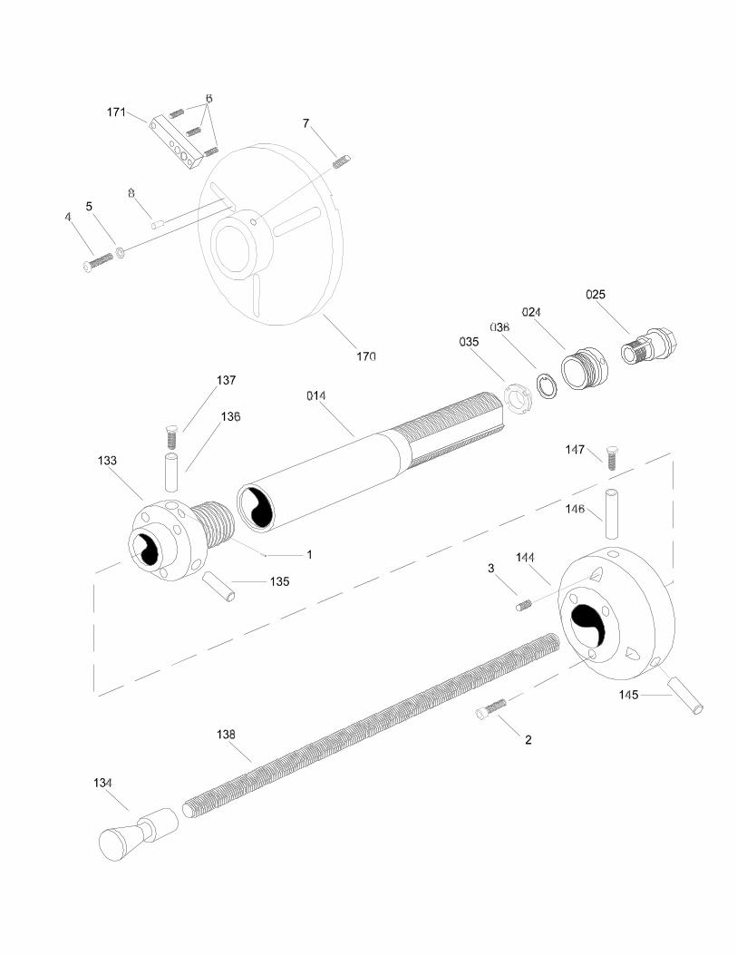
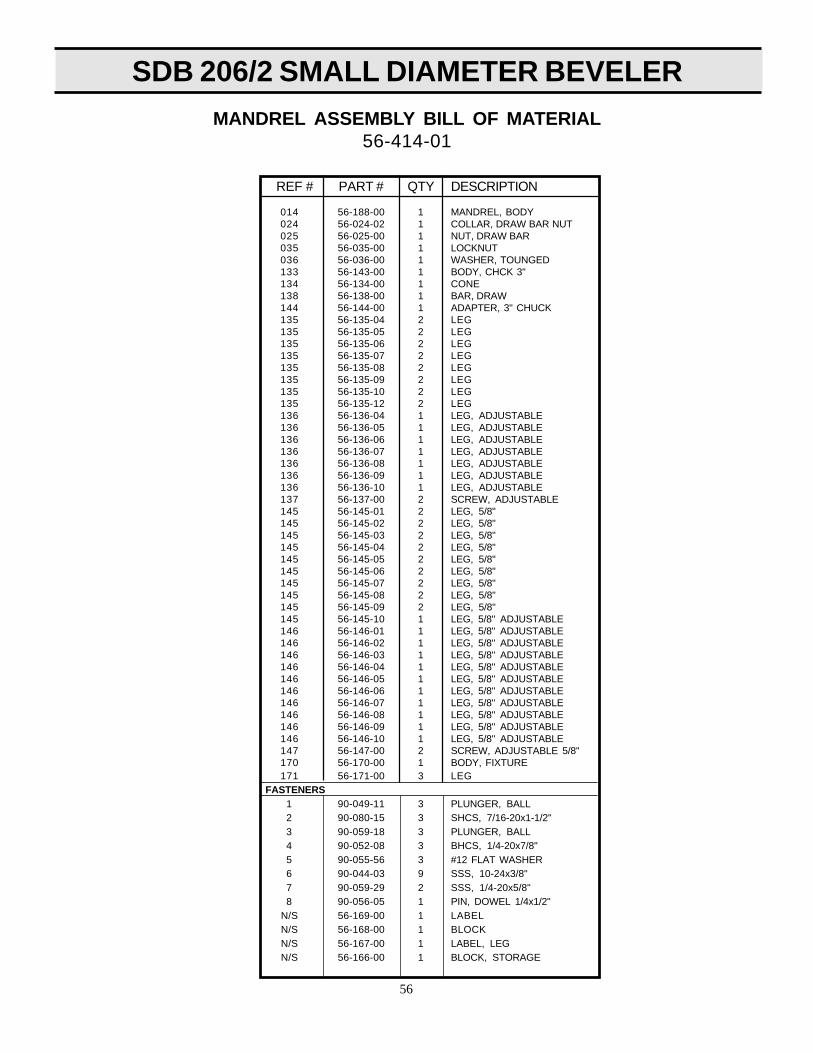
56
MANDREL ASSEMBLY BILL OF MATERIAL56-414-01
REF # PART # QTY DESCRIPTION
014 56-188-00 1 MANDREL, BODY024 56-024-02 1 COLLAR, DRAW BAR NUT025 56-025-00 1 NUT, DRAW BAR035 56-035-00 1 LOCKNUT036 56-036-00 1 WASHER, TOUNGED133 56-143-00 1 BODY, CHCK 3"134 56-134-00 1 CONE138 56-138-00 1 BAR, DRAW144 56-144-00 1 ADAPTER, 3" CHUCK135 56-135-04 2 LEG135 56-135-05 2 LEG135 56-135-06 2 LEG135 56-135-07 2 LEG135 56-135-08 2 LEG135 56-135-09 2 LEG135 56-135-10 2 LEG135 56-135-12 2 LEG136 56-136-04 1 LEG, ADJUSTABLE136 56-136-05 1 LEG, ADJUSTABLE136 56-136-06 1 LEG, ADJUSTABLE136 56-136-07 1 LEG, ADJUSTABLE136 56-136-08 1 LEG, ADJUSTABLE136 56-136-09 1 LEG, ADJUSTABLE136 56-136-10 1 LEG, ADJUSTABLE137 56-137-00 2 SCREW, ADJUSTABLE145 56-145-01 2 LEG, 5/8"145 56-145-02 2 LEG, 5/8"145 56-145-03 2 LEG, 5/8"145 56-145-04 2 LEG, 5/8"145 56-145-05 2 LEG, 5/8"145 56-145-06 2 LEG, 5/8"145 56-145-07 2 LEG, 5/8"145 56-145-08 2 LEG, 5/8"145 56-145-09 2 LEG, 5/8"145 56-145-10 1 LEG, 5/8" ADJUSTABLE146 56-146-01 1 LEG, 5/8" ADJUSTABLE146 56-146-02 1 LEG, 5/8" ADJUSTABLE146 56-146-03 1 LEG, 5/8" ADJUSTABLE146 56-146-04 1 LEG, 5/8" ADJUSTABLE146 56-146-05 1 LEG, 5/8" ADJUSTABLE146 56-146-06 1 LEG, 5/8" ADJUSTABLE146 56-146-07 1 LEG, 5/8" ADJUSTABLE146 56-146-08 1 LEG, 5/8" ADJUSTABLE146 56-146-09 1 LEG, 5/8" ADJUSTABLE146 56-146-10 1 LEG, 5/8" ADJUSTABLE147 56-147-00 2 SCREW, ADJUSTABLE 5/8"170 56-170-00 1 BODY, FIXTURE171 56-171-00 3 LEG
FASTENERS1 90-049-11 3 PLUNGER, BALL2 90-080-15 3 SHCS, 7/16-20x1-1/2"3 90-059-18 3 PLUNGER, BALL4 90-052-08 3 BHCS, 1/4-20x7/8"5 90-055-56 3 #12 FLAT WASHER6 90-044-03 9 SSS, 10-24x3/8"7 90-059-29 2 SSS, 1/4-20x5/8"8 90-056-05 1 PIN, DOWEL 1/4x1/2"
N/S 56-169-00 1 LABELN/S 56-168-00 1 BLOCKN/S 56-167-00 1 LABEL, LEGN/S 56-166-00 1 BLOCK, STORAGE


SDB 206/2 SMALL DIAMETER BEVELER
58
PART NO. NAME OF PART QTY.
Spindle (mcI. 844010, 844011 & 844014)Spindle Needle Bearing2nd Red. Idler Gear Bearing2nd Red. Idler Gear-i 5T (mcI. 203062)SpindleSpindle Housing AdaptorSpindle Housing2nd Red. Spider-i 9TRetainer RingSpindle Ball Bearing1st Red. Gear PinSpring RetainerSocket Lock Pin
202533-6202536-9203062-5203107-8203137-5203696-0203697-8203698-9203699-4619466-6832125-9844010-9844011-7
1631111111311
PARTS LIST - GEAR TRAIN
Lock Pin Spring1st Red. Idler Gear Bearing1st Red. Spider-19T (md 832125)2nd Red. Idler Gear Pin2nd Red. Spider Ball Bearing1st Red. Idler Gear Bearing-21T(mcI. 844774)Spindle Ball Bearing Retainer Ring3rd Red. Idler Gear-15T3rd Red. Spider3rd Red. Needle Roller3rd Red. Idler Gear PinSpindle Retainer Ring
844014-1844774-0861485-1864671-3865198-6867526-6
869877-1869906-5869905-0869907-9869908-4882115-9
13131
31313931
PART NO. NAME OF PART QTY.
869907-9 (13 PER GEAR)
869903-5
869908-4
869905-0
203696-4
203699-4
865198-6
203698-9
203107-8
203062-5
864671-3
861485-1
867526-6
844774-0
832125-9
203137-5 - 1/2” SQ. DR.NO RETAINER
844011-7
844014-1844010-9
202533-6
202536-9
202697-8 619466-6
869877-1
882115-9
NO. 55NAL-1 & 55NL-1 NUTRUNNER GEAR TRAINS

SDB 206/2 SMALL DIAMETER BEVELER
59
PART NO. NAME OF PART QTY.PART NO. NAME OF PART QTY.
TRIP SLEEVE SPRINGCLUTCH CAM BEARINGSTEEL BALL 3/16” DIA.STEEL BALL 5/16” DIA.STEEL BALL 1/8” DIA.WASHER RETAINER RINGPINPIN SPRINGSPIRAL RINGDRIVE SHAFT WASHERTRIP PLUNGERTORQUE SPRING PLATE
202056-8619377-5842161-2844077-8844265-9847022-1864711-7864712-5865436-0867666-0867668-6867669-4
115161111111
PARTS LIST - CLECOMATIC CLUTCH
TRIP SLEEVETRIP PLUNGER SPRINGBALL RETAINERDRIVE SHAFTCLUTCH CAMADJUSTMENT HOLE COVERADJUSTMENT NUTCLUTCH HOUSING (INCL. 864711-7,864712-5, 869263-4)TORQUE SPRING BEARINGPIN SLEEVETORQUE SPRING
111111111111
867670-2867671-0867673-6867674-4867676-9867677-7867678-5867681-9
867683-5869263-4869626-2
NO. 55NAL-1 CLECOMATIC CLUTCH
869626-2 867669-4 867683-5 867678-5
844265-9 842161-2
865436-0
867673-6 867670-2 202056-8 867666-0
847022-1
867668-6867671-0867676-9619377-5
842161-2
867681-9
864712-5
869263-4
864711-7 844077-8 867677-7
867674-4

SDB 206/2 SMALL DIAMETER BEVELER
60
203100-3203101-1203102-92031 03-7203989-961 9377-58121 65-9843444-1847096-5847603-8863468-5863887-6865352-9869059-6869569-4867536-5869660-1869570-2869572-8869573-6
ROTOR-HEX (NON-REV. AUTOMATIC SHUT-OFF)CYLINDER NON-REVERSIBLE) - INCL. 8863887-6ROTOR-7T NON-REVERSIBLE STALL)CYLINDER REVERSIBLE) - INCL. 8121 64-2BEARING CAP (STALL TOOL ONLY)FRONT ROTOR BEARINGREVERSIBLE CYLINDER PINREAR ROTOR BEARING (NON-REVERSIBLE)REAR ROTOR BEARING (REVERSIBLE)ALIGNMENT PIN (REVERSIBLE)TRIP ROD (AUTOMATIC SHUT-OFF)NON-REVERSIBLE CYLINDER PINROTOR LOCK NUTFRONT BEARING PLATEMOTOR SPACER (STALL ONLY) ROTOR BLADEROTOR BLADEREAR BEARING PLATE (REVERSIBLE)ROTOR-HEX (REVERSIBLE AUTOMATIC SHUT-OFF)REAR BEARING PLATE (NON-REVERSIBLE)ROTOR-7T (REVERSIBLE STALL)
PART NO. NAME OF PART QTY.
11111111111111151111
PARTS LIST - MOTOR
NO. 55NAL-1 & 55NL-1 MOTOR
869059-6Stall Tools Only
619377-5
867536-5
869569-4
847603-8Rev. Models Only
865352-9
863468-5Automatic Shut-off
Tools Only
203989-9Stall Tools Only
847096-5843444-1 Non-Rev.
Rev.
869660-1869572-8 Non-Rev.
Rev.
863887-6812165-9 Rev.
Non-Rev.
203103-7203101-1 Non-Rev.
Rev.
Reversible Tools (Star Rotor)869573-6 Stall Tools
Automatic Shut-off Tools869570-2
Non-Reversible Tools (Round Rotor)203102-9 Stall Tools
Automatic Shut-off Tools203100-3

SDB 206/2 SMALL DIAMETER BEVELER
61
PART NO. NAME OF PART QTY.SEAL RINGTHROTTLE VALVELOCK-OFF LEVER PAWLTHROTTLE VALVE PININLET SPACEREXHAUST DEFLECTORREVERSING VALVE SLEEVEMUFFLERMUFFLERMOTOR HOUSING (NON-REV.)MOTOR HOUSING (REV.)INLET BUSHINGMETERING NUTLOCK-OFF LEVER‘O’-RING 2 X 2-1/8’‘O’-RING 1-9/16’ X 1-3/4’‘O’-RING 7/8’ X 1-1/16’
202011-3202055-0202105-5202481-8202508-8202626-8202628-4202632-6203109-4203110-2203111-0204178-8617754-7619164-7622062-8
11111111111111211
PARTS LIST - HANDLE
622881-1832079-8843656-0845409-2847275-5*863468-5*864195-3864973-3865063-2867554-8867667-8*867682-T*869655-1869659-3869855-7869931-6
PART NO. NAME OF PART QTY.“O”-RING 7/8” x 1-1/18”SPRINGAIR INLETLOCK-OFF LEVER PAWL RETAINER PIN“O”-RING 1-1/16” x 1-3/16”TRIP RODLEVER PINTHROTTLE VALVE SPRINGTHROTTLE LEVERREVERSING VALVE SCREWSHUT-OFF VALVEVALVE BLOCKMOTOR SPACERREVERSING VALVELOCK-OFF LEVER SPRINGTHROTTLE VALVE SEAT
1111111111111111
* Denotes parts not included in subassemblies listed below.
869931-6 864973-3 202508-8 203202-7 203203-5
832079-8622881-1843656-0202055-0622062-8
202011-3
202632-8 202626-8
203109-4
202628-4
617754-7
869659-3
REVERSIBLEONLY
619164-7869655-1
867667-8Clecomatic only
847275-5867667-8
867682-7Non-reversibleAutomaticShut-offtools only
863468-5Automatic Shut-off Only
864195-3
865063-2
202481-8
867554-8
Reversible Only
845409-2
869855-7
202105-3
864195-3
204178-8
LOCK-OFFLEVER
203111-0203110-2 Non-Rev.
Rev.
NO. 55 NAL-1 & NL-1 HANDLE

SDB 206/2 SMALL DIAMETER BEVELER
62
To place an order or to get more detailed information on any E.H. Wachs products, call us at:1-800-323-8185.
ORDERING REPLACEMENT PARTS
Please use parts list provided in manual. Have part description and part number of requiredreplacement part or parts to help expedite order and insure proper parts are being ordered.
REPAIR INFORMATION
Please call E.H. Wachs Company prior to returning any equipment for repair. We will advise youof shipping and handling. Please enclose with equipment to be repaired your name, address,phone number and a brief description of problem or work to be done or estimated.
All repair work done at our plant will be estimated and the customer advised of cost and timerequired to complete repair.
WARRANTY INFORMATION
Enclosed with the manual is a warranty card. Please fill out the registration card and return to E.H.Wachs. Retain the owners registration record and warranty card for your information.
RETURN GOODS ADDRESS
E.H. Wachs Company100 Shepard Street
Wheeling, Illinois 60090
Call or Write:
E.H. Wachs CompanyP.O. Box A
100 Shepard StreetWheeling, Illinois 60090
847-537-8800 WorlwideToll-Free: 1-800-323-8185 in USA
Fax: 847-520-1147 • Fax: 800-922-4755
visit us on the web at: http://www.wachsco.com
SECTION IX ORDERING INFORMATION


![[XLS]kuk.results.tripod.comkuk.results.tripod.com/BTECH1C.xls · Web viewSurender Tinku 05 sdb 352 05 sdb 120 05 sdb 395 05 sdb 433 05 sdb 467 05 sdb 458 05 sdb 359 05 sdb 370 05](https://static.fdocuments.net/doc/165x107/5ae703757f8b9aee078da099/xlskuk-viewsurender-tinku-05-sdb-352-05-sdb-120-05-sdb-395-05-sdb-433-05-sdb.jpg)