Service Manual TGM DC Iverter(2009 08) - Página Principal …€¦ · · 2015-09-28Service...
48
Transcript of Service Manual TGM DC Iverter(2009 08) - Página Principal …€¦ · · 2015-09-28Service...


Content
- 1 -
Content
1 Precaution ...................................................................................................................... 2
1.1 Safety Precaution ............................................................................................................................. 2
1.2 Warning ............................................................................................................................................ 2
2 Function ........................................................................................................................ 5
3 Dimension ....................................................................................................................... 7
4 Specification ................................................................................................................... 8
5 Refrigerant cycle diagram ........................................................................................... 16
6 Operation limits ............................................................................................................ 17
7 Wiring diagram ............................................................................................................. 17
8 Installation details ........................................................................................................ 24
8.1 Wrench torque sheet for installation .................................................................................................. 24
8.2 Connecting the cables ...................................................................................................................... 24
8.3 Pipe length and the elevation ............................................................................................................ 24
8.4 Air purging of the piping and indoor unit ........................................................................................... 25
8.5 Pumping down (Re-installation) ........................................................................................................ 26
8.6 Re-air purging (Re-installation) ......................................................................................................... 27
8.7 Balance refrigerant of the 2-way, 3-way valves ................................................................................. 28
8.8 Evacuation ........................................................................................................................................ 29
8.9 Gas charging .................................................................................................................................... 30
9 Electronic function ...................................................................................................... 31
9.1 Abbreviation ................................................................................................................................... 31
9.2 Display function .............................................................................................................................. 31
9.3 Protection ....................................................................................................................................... 32
9.4 Fan-Only Mode .............................................................................................................................. 33
9.5 Cooling Mode ................................................................................................................................. 33
9.6 Drying mode ................................................................................................................................... 34
9.7 Heating mode ................................................................................................................................. 35
9.8 Auto mode function ........................................................................................................................ 38
9.9 Forced operation function ............................................................................................................... 38
9.10 Action of 4-way valve ................................................................................................................... 38
9.11 Two speeds outdoor fan function .................................................................................................. 39
9.12 Timer function ............................................................................................................................... 39
9.13 Sleep function mode..................................................................................................................... 39
9.14 Auto-Restart function .................................................................................................................... 40
9.15 Automatic panel function .............................................................................................................. 40
9.16 Ionizer (Clean Air) function ........................................................................................................... 40
9.17 Self-clean function ........................................................................................................................ 40
9.18 Follow me function ....................................................................................................................... 41
9.19 Outdoor chassis heating cable function (optional) ........................................................................ 41
10 Troubleshooting ........................................................................................................... 42
10.1 Indoor Unit Error Display .............................................................................................................. 43
10.2 Diagnosis and Solution ................................................................................................................. 43
Service manual
- 2 -
1 Precaution
1.1 Safety Precaution
To prevent injury to the user or other people and property damage, the following instructions must be
followed.
Incorrect operation due to ignoring instruction will cause harm or damage.
Before service unit, be sure to read this service manual at first.
1.2 Warning
Installation Do not use a defective or underrated circuit breaker. Use this appliance on a dedicated circuit.
There is risk of fire or electric shock.
For electrical work, contact the dealer, seller, a qualified electrician, or an Authorized service center.
Do not disassemble or repair the product, there is risk of fire or electric shock.
Always ground the product.
There is risk of fire or electric shock.
Install the panel and the cover of control box securely.
There is risk of fire of electric shock.
Always install a dedicated circuit and breaker.
Improper wiring or installation may cause fore or electric shock.
Use the correctly rated breaker of fuse.
There is risk of fire or electric shock.
Do not modify or extend the power cable.
There is risk of fire or electric shock.
Do not install, remove, or reinstall the unit by yourself (customer).
There is risk of fire, electric shock, explosion, or injury.
Be caution when unpacking and installing the product.
Sharp edges could cause injury, be especially careful of the case edges and the fins on the condenser and evaporator.
For installation, always contact the dealer or an Authorized service center.
There is risk of fire, electric shock, explosion, or injury.
Do not install the product on a defective installation stand.
It may cause injury, accident, or damage to the product.
Be sure the installation area does not deteriorate with age.
If the base collapses, the air conditioner could fall with it, causing property damage, product failure, and personal injury.
Do not let the air conditioner run for a long time when the humidity is very high and a door or a window is
left open.
Moisture may condense and wet or damage furniture.
Take care to ensure that power cable could not be pulled out or damaged during operation.
There is risk of fire or electric shock.
Do not place anything on the power cable.
There is risk of fire or electric shock.
Do not plug or unplug the power supply plug during operation.
There is risk of fire or electric shock.
Do not touch (operation) the product with wet hands.
There is risk of fire or electric shock.

Service manual
- 3 -
Do not place a heater or other appliance near the power cable.
There is risk of fire and electric shock.
Do not allow water to run into electric parts.
It may cause fire, failure of the product, or electric shock.
Do not store or use flammable gas or combustible near the product.
There is risk of fire or failure of product.
Do not use the product in a tightly closed space for a long time.
Oxygen deficiency could occur.
When flammable gas leaks, turn off the gas and open a window for ventilation before turn the product on.
Do not use the telephone or turn switches on or off. There is risk of explosion or fire.
If strange sounds, or small or smoke comes from product. Turn the breaker off or disconnect the power
supply cable.
There is risk of electric shock or fire.
Stop operation and close the window in storm or hurricane. If possible, remove the product from the
window before the hurricane arrives.
There is risk of property damage, failure of product, or electric shock.
Do not open the inlet grill of the product during operation. (Do not touch the electrostatic filter, if the unit is
so equipped.)
There is risk of physical injury, electric shock, or product failure.
When the product is soaked (flooded or submerged), contact an Authorized service center.
There is risk of fire or electric shock.
Be caution that water could not enter the product.
There is risk of fire, electric shock, or product damage.
Ventilate the product from time to time when operating it together with a stove, etc.
There is risk of fire or electric shock.
Turn the main power off when cleaning or maintaining the product.
There is risk of electric shock.
When the product is not be used for a long time, disconnect the power supply plug or turn off the breaker.
There is risk of product damage or failure, or unintended operation.
Take care to ensure that nobody could step on or fall onto the outdoor unit.
This could result in personal injury and product damage.
CAUTION Always check for gas (refrigerant) leakage after installation or repair of product.
Low refrigerant levels may cause failure of product.
Install the drain hose to ensure that water is drained away properly.
A bad connection may cause water leakage.
Keep level even when installing the product.
To avoid vibration of water leakage.
Do not install the product where the noise or hot air from the outdoor unit could damage the
neighborhoods.
It may cause a problem for your neighbors.
Use two or more people to lift and transport the product.
Avoid personal injury.
Do not install the product where it will be exposed to sea wind (salt spray) directly.
It may cause corrosion on the product. Corrosion, particularly on the condenser and evaporator fins, could cause product malfunction or inefficient operation.
Operational Do not expose the skin directly to cool air for long periods of time. (Do not sit in the draft).
This could harm to your health.
Service manual
- 4 -
Do not use the product for special purposes, such as preserving foods, works of art, etc. It is a consumer
air conditioner, not a precision refrigerant system.
There is risk of damage or loss of property.
Do not block the inlet or outlet of air flow.
It may cause product failure.
Use a soft cloth to clean. Do not use harsh detergents, solvents, etc.
There is risk of fire, electric shock, or damage to the plastic parts of the product.
Do not touch the metal parts of the product when removing the air filter. They are very sharp.
There is risk of personal injury.
Do not step on pr put anything on the product. (outdoor units)
There is risk of personal injury and failure of product.
Always insert the filter securely. Clean the filter every two weeks or more often if necessary.
A dirty filter reduces the efficiency of the air conditioner and could cause product malfunction or damage.
Do not insert hands or other object through air inlet or outlet while the product is operated.
There are sharp and moving parts that could cause personal injury.
Do not drink the water drained from the product.
It is not sanitary could cause serious health issues.
Use a firm stool or ladder when cleaning or maintaining the product.
Be careful and avoid personal injury.
Replace the all batteries in the remote control with new ones of the same type. Do not mix old and mew
batteries or different types of batteries.
There is risk of fire or explosion.
Do not recharge or disassemble the batteries. Do not dispose of batteries in a fire.
They may burn of explode.
If the liquid from the batteries gets onto your skin or clothes, wash it well with clean water. Do not use the
remote of the batteries have leaked.
The chemical in batteries could cause burns or other health hazards

Service manual
- 5 -
2 Function
Maintain the room temperature in accordance with the setting temperature.
The mode can be change by the room temperature.
The louver can be set at the desired position or swing up and down automatically
The function is usually used in rainy days in springtime or damp areas.
The fan is turn to low speed (cooling/heating).The unit will be turn off at the seventh hour.
The unit will decide the louver direction according to operation mode.
Turbo wind, high, med, low, breeze.
Restarting is for approx. 3 minutes..
Prevent the water being frozen on evaporator by sensing the evaporator pipe temperature in cooling mode
Room temperature sensor. Pipe temperature sensor.
Indoor unit
Operation by remote controller
Sensing by room temperature
Room temperature control
Anti-freezing control in cooling
Time Delay Safety control
Indoor fan speed control
Two-direction air vane
Sleep mode auto control
Independent dehumidification
Air flow Direction control
Auto mode
Temp. Compensation Flexible wiring connection
Auto defrost
Follow me
Anti-cold function
Self-diag. function
Auto-restart function
Timer function
Self clean
Prevent the cold wind at the beginning of unit start.
Ionizer

Service manual
- 6 -
It protects the valves and prevents water from dripping.
The unit has 3 mins delay between continuously ON/OFF operations.
Outdoor unit
Power relay control
The hydrophilic fin can improve the heating efficiency at operation mode.
Hydrophilic aluminum fin
It is only operated in the heating operation mode except defrosting operation.
Anti-rust cabinet
Valve protection cover
4 way valve control
Made from electrolytic zinc steel sheet and anti-rust coated components.
Low noise air flow system
Bird tail propeller fan makes the outdoor unit run more quietly.
Discharge pipe temperature protect
Heating cable (Optional)
Driving heating at -15

Service manual
- 7 -
3 Dimension
Indoor unit:
Dimension
Model W H D
9K 795 270 165
12K 845 286 165
18K 995 292 194
24K 1180 320 200
Outdoor unit:
Dimension
Model W H D L1 L2
9K, 12K Cooling 780 540 250 549 266
9K, 12K Cooling & Heating
18K Cooling 760 590 290 530 315
18K Cooling & Heating 845 695 335 560 360
24K 895 860 330 560 360

Service manual
- 8 -
4 Specification
Table 1:
Model MWVT09S/ MRVT09AS MWHVT09S/ MRHVT09AS
Indoor MWVT09S MWHVT09S
Outdoor MRVT09S MRHVT09S
Power supply Ph-V-Hz 1Ph, 220-230V~, 60Hz 1Ph, 220-230V~, 60Hz
Cooling
Capacity Btu/h 9000(3300~11200) 9000(3300~11200)
Input W 850(240~1200) 830(240~1200)
Rated current A 4.8(1.2~5.3) 4.1(1.2~5.3)
EER W/W 3.2 3.2
Heating
Capacity Btu/h ----- 10000(4000~13000)
Input W ----- 820(240~1250)
Rated current A ----- 4.1(1.2~5.6)
COP W/W ----- 3.6
Moisture Removal L/h 1.0 1.0
Max. input consumption W 1750 1750
Max. current A 8.0 8.0
Compressor
Model DA89X1C-23FZ DA108X1C-20FZ3
Type ROTARY ROTARY
Brand TOSHIBA TOSHIBA
Capacity Btu/h 9040 10918
Input W 680 855
Rated current(RLA) A 4.7 5.3
Locked rotor Amp(LRA) A 10 10
Thermal protector CS-74 INT01L-4639 / CS-74
Thermal protector position internal EXTERNAL
Capacitor uF 35 35
Refrigerant oil/oil charge ml ESTER OIL VG74 370 ml ESTER OIL VG74 / 480
Indoor fan motor
Model RPG20B RPG20B
Brand Welling Welling
Input W 43 43
Capacitor uF 1.5 1.5
Speed(Hi/Mi/Lo) r/min 1100/1000/850 1100/1000/850
Indoor coil
Number of rows 2/1 2/1
Tube pitch(a)x row pitch(b) mm 21x13.37 21x13.37
Fin spacing mm 1.3 1.3
Fin type (code) Hydrophilic aluminium Hydrophilic aluminium
Tube outside dia. and type mm φ7 INNEGROOVE TUBE φ7 INNEGROOVE TUBE
Coil length x height x width mm 621X(189+126)X(26.74+13.37) 621X(189+126)X(26.74+13.37)
Number of circuits 2 2
Indoor air flow (Hi/Mi/Lo) m3/h 540/490/420 540/490/420
Indoor noise level (Hi/Mi/Lo) dB(A) 38/35/32 38/35/32
Service manual
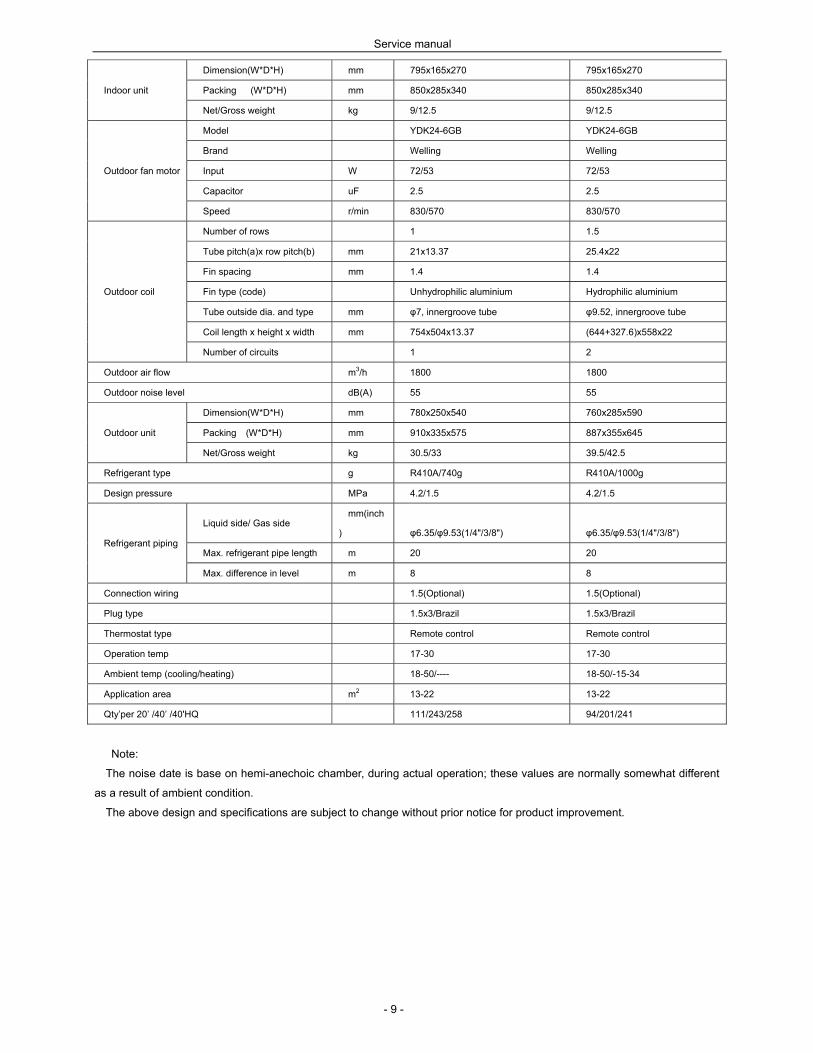
- 9 -
Indoor unit
Dimension(W*D*H) mm 795x165x270 795x165x270
Packing (W*D*H) mm 850x285x340 850x285x340
Net/Gross weight kg 9/12.5 9/12.5
Outdoor fan motor
Model YDK24-6GB YDK24-6GB
Brand Welling Welling
Input W 72/53 72/53
Capacitor uF 2.5 2.5
Speed r/min 830/570 830/570
Outdoor coil
Number of rows 1 1.5
Tube pitch(a)x row pitch(b) mm 21x13.37 25.4x22
Fin spacing mm 1.4 1.4
Fin type (code) Unhydrophilic aluminium Hydrophilic aluminium
Tube outside dia. and type mm φ7, innergroove tube φ9.52, innergroove tube
Coil length x height x width mm 754x504x13.37 (644+327.6)x558x22
Number of circuits 1 2
Outdoor air flow m3/h 1800 1800
Outdoor noise level dB(A) 55 55
Outdoor unit
Dimension(W*D*H) mm 780x250x540 760x285x590
Packing (W*D*H) mm 910x335x575 887x355x645
Net/Gross weight kg 30.5/33 39.5/42.5
Refrigerant type g R410A/740g R410A/1000g
Design pressure MPa 4.2/1.5 4.2/1.5
Refrigerant piping
Liquid side/ Gas side mm(inch
) φ6.35/φ9.53(1/4"/3/8") φ6.35/φ9.53(1/4"/3/8")
Max. refrigerant pipe length m 20 20
Max. difference in level m 8 8
Connection wiring 1.5(Optional) 1.5(Optional)
Plug type 1.5x3/Brazil 1.5x3/Brazil
Thermostat type Remote control Remote control
Operation temp 17-30 17-30
Ambient temp (cooling/heating) 18-50/---- 18-50/-15-34
Application area m2 13-22 13-22
Qty’per 20’ /40’ /40'HQ 111/243/258 94/201/241
Note:
The noise date is base on hemi-anechoic chamber, during actual operation; these values are normally somewhat different
as a result of ambient condition.
The above design and specifications are subject to change without prior notice for product improvement.
Service manual
- 10 -
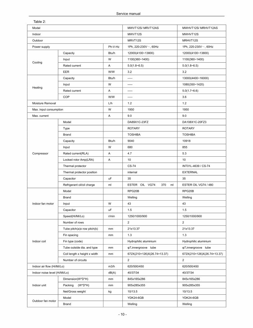
Table 2:
Model MWVT12S/ MRVT12AS MWHVT12S/ MRHVT12AS
Indoor MWVT12S MWHVT12S
Outdoor MRVT12S MRHVT12S
Power supply Ph-V-Hz 1Ph, 220-230V~, 60Hz 1Ph, 220-230V~, 60Hz
Cooling
Capacity Btu/h 12000(4100~13800) 12000(4100~13800)
Input W 1100(360~1400) 1100(360~1400)
Rated current A 5.0(1.8~6.5) 5.0(1.8~6.5)
EER W/W 3.2 3.2
Heating
Capacity Btu/h ----- 13000(4400~16000)
Input W ----- 1080(350~1420)
Rated current A ----- 5.0(1.7~6.6)
COP W/W ----- 3.6
Moisture Removal L/h 1.2 1.2
Max. input consumption W 1950 1950
Max. current A 9.0 9.0
Compressor
Model DA89X1C-23FZ DA108X1C-20FZ3
Type ROTARY ROTARY
Brand TOSHIBA TOSHIBA
Capacity Btu/h 9040 10918
Input W 680 855
Rated current(RLA) A 4.7 5.3
Locked rotor Amp(LRA) A 10 10
Thermal protector CS-74 INT01L-4639 / CS-74
Thermal protector position internal EXTERNAL
Capacitor uF 35 35
Refrigerant oil/oil charge ml ESTER OIL VG74 370 ml ESTER OIL VG74 / 480
Indoor fan motor
Model RPG20B RPG20B
Brand Welling Welling
Input W 43 43
Capacitor uF 1.5 1.5
Speed(Hi/Mi/Lo) r/min 1250/1000/900 1250/1000/900
Indoor coil
Number of rows 2 2
Tube pitch(a)x row pitch(b) mm 21x13.37 21x13.37
Fin spacing mm 1.3 1.3
Fin type (code) Hydrophilic aluminium Hydrophilic aluminium
Tube outside dia. and type mm φ7,innergroove tube φ7,innergroove tube
Coil length x height x width mm 672X(210+126)X(26.74+13.37) 672X(210+126)X(26.74+13.37)
Number of circuits 2 2
Indoor air flow (Hi/Mi/Lo) m3/h 620/500/450 620/500/450
Indoor noise level (Hi/Mi/Lo) dB(A) 40/37/34 40/37/34
Indoor unit
Dimension(W*D*H) mm 845x165x286 845x165x286
Packing (W*D*H) mm 905x285x355 905x285x355
Net/Gross weight kg 10/13.5 10/13.5
Outdoor fan motor Model YDK24-6GB YDK24-6GB
Brand Welling Welling

Service manual
- 11 -
Input W 72/53 72/53
Capacitor uF 2.5 2.5
Speed r/min 830/570 830/570
Outdoor coil
Number of rows 2 2
Tube pitch(a)x row pitch(b) mm 21x13.37 22x19.05
Fin spacing mm 1.5 1.4
Fin type (code) Unhydrophilic aluminium Hydrophilic aluminium
Tube outside dia. and type mm φ7, innergroove tube φ7.94, innergroove tube
Coil length x height x width mm 744x504x26.67 656x550x38.1
Number of circuits 2 4
Outdoor air flow m3/h 1800 1800
Outdoor noise level dB(A) 56 56
Outdoor unit
Dimension(W*D*H) mm 780x250x540 760x285x590
Packing (W*D*H) mm 910x335x575 887x355x645
Net/Gross weight kg 33/35.5 35/37
Refrigerant type g R410A/1050g R410A/1100g
Design pressure MPa 4.2/1.5 4.2/1.5
Refrigerant piping
Liquid side/ Gas side mm(inch
) φ6.35 / φ12.7(1/4"/1/2") φ6.35 / φ12.7(1/4"/1/2")
Max. refrigerant pipe length m 20 20
Max. difference in level m 8 8
Connection wiring 1.5(Optional) 1.5(Optional)
Plug type 1.5x3/Brazil 1.5x3/Brazil
Thermostat type Remote control Remote control
Operation temp 17-30 17-30
Ambient temp (cooling/heating) 18-50/---- 18-50/-15-34
Application area m2 18-29 18-29
Qty’per 20’ /40’ /40'HQ 105/227/253 95/196/237
Note:
The noise date is base on hemi-anechoic chamber, during actual operation; these values are normally somewhat different
as a result of ambient condition.
The above design and specifications are subject to change without prior notice for product improvement.

Service manual
- 12 -
Table 3:
Model MWVT18S/ MRVT18AS MWHVT18S/ MRHVT18AS
Indoor MWVT18S MWHVT18S
Outdoor MRVT18S MRHVT18S
Power supply Ph-V-Hz 1Ph, 220-230V~, 60Hz 1Ph, 220-230V~, 60Hz
Cooling
Capacity Btu/h 18000(5400-19000) 18000(5400-19000)
Input W 1720(750-2000) 1700(750-2000)
Rated current A 8.3(3.2-9.0) 8.3(3.2-9.0)
EER W/W 3.0 3.0
Heating
Capacity Btu/h ----- 18000(5700-19800)
Input W ----- 1520(720-2050)
Rated current A ----- 8.0(3.2-10.0)
COP W/W ----- 3.3
Moisture Removal L/h 1.8 1.8
Max. input consumption W 2300 2300
Max. current A 13.0 13.0
Compressor
Model C-6RVN93H0N C-6RVN93H0N
Type Rotary Rotary
Brand SANYO SANYO
Capacity Btu/h 19892 19892
Input W 1430 1430
Rated current(RLA) A 7.46 7.46
Locked rotor Amp(LRA) A 10.7 10.7
Thermal protector 1NT11L-3979 1NT11L-3979
Thermal protector position Internal Internal
Capacitor uF 35 35
Refrigerant oil/oil charge ml FV50S/400 FV50S/400
Indoor fan motor
Model RPG28H RPG28H
Brand Welling Welling
Input W 58.5 58.5
Capacitor uF 1.5 1.5
Speed(Hi/Mi/Lo) r/min 1250/1100/1000 1250/1100/1000
Indoor coil
Number of rows 2 2
Tube pitch(a)x row pitch(b) mm 21x13.37 21x13.37
Fin spacing mm 1.3 1.3
Fin type (code) Hydrophilic aluminium Hydrophilic aluminium
Tube outside dia. and type mm φ7, innergroove tube φ7, innergroove tube
Coil length x height x width mm 808x336x26.67 808x336x26.67
Number of circuits 4 4
Indoor air flow (Hi/Mi/Lo) m3/h 770/680/600 770/680/600
Indoor noise level (Hi/Mi/Lo) dB(A) 41/38/35 41/38/35
Indoor unit
Dimension(W*D*H) mm 995x194x292 995x194x292
Packing (W*D*H) mm 1100x290x415 1100x290x415
Net/Gross weight kg 11.5/15 11.5/15
Outdoor fan motor Model YDK50-6B YDK53-6FB
Brand Welling Welling
Service manual
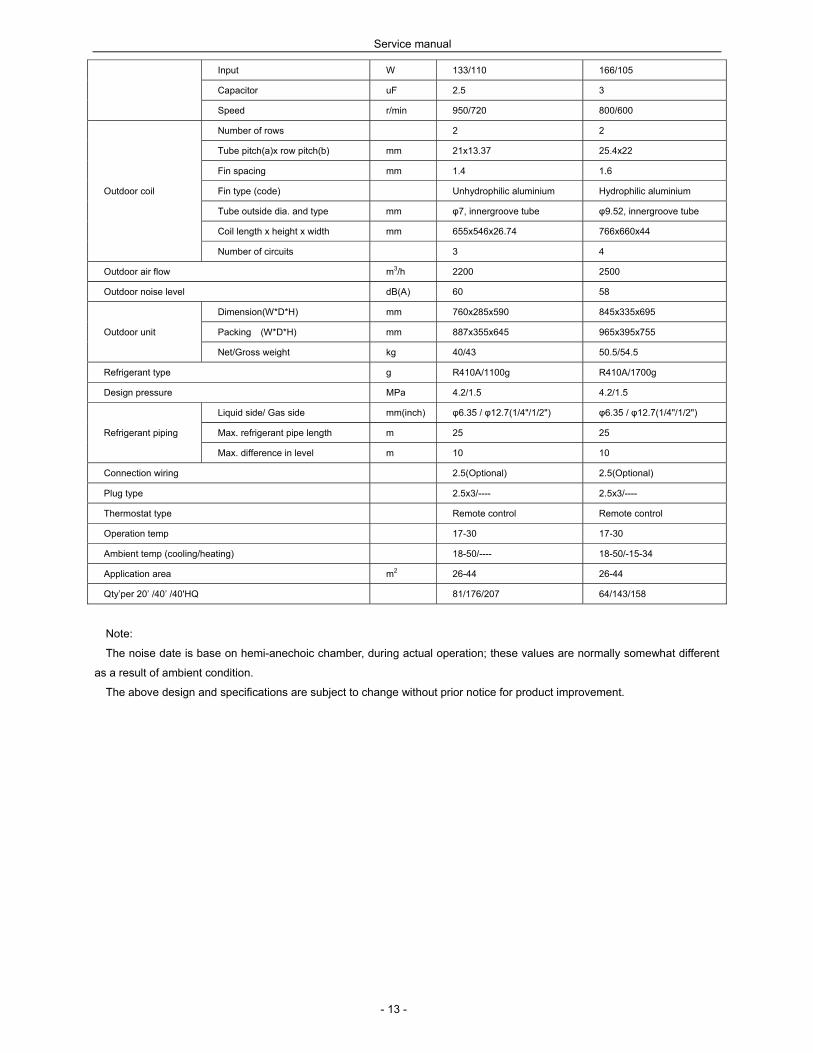
- 13 -
Input W 133/110 166/105
Capacitor uF 2.5 3
Speed r/min 950/720 800/600
Outdoor coil
Number of rows 2 2
Tube pitch(a)x row pitch(b) mm 21x13.37 25.4x22
Fin spacing mm 1.4 1.6
Fin type (code) Unhydrophilic aluminium Hydrophilic aluminium
Tube outside dia. and type mm φ7, innergroove tube φ9.52, innergroove tube
Coil length x height x width mm 655x546x26.74 766x660x44
Number of circuits 3 4
Outdoor air flow m3/h 2200 2500
Outdoor noise level dB(A) 60 58
Outdoor unit
Dimension(W*D*H) mm 760x285x590 845x335x695
Packing (W*D*H) mm 887x355x645 965x395x755
Net/Gross weight kg 40/43 50.5/54.5
Refrigerant type g R410A/1100g R410A/1700g
Design pressure MPa 4.2/1.5 4.2/1.5
Refrigerant piping
Liquid side/ Gas side mm(inch) φ6.35 / φ12.7(1/4"/1/2") φ6.35 / φ12.7(1/4"/1/2")
Max. refrigerant pipe length m 25 25
Max. difference in level m 10 10
Connection wiring 2.5(Optional) 2.5(Optional)
Plug type 2.5x3/---- 2.5x3/----
Thermostat type Remote control Remote control
Operation temp 17-30 17-30
Ambient temp (cooling/heating) 18-50/---- 18-50/-15-34
Application area m2 26-44 26-44
Qty’per 20’ /40’ /40'HQ 81/176/207 64/143/158
Note:
The noise date is base on hemi-anechoic chamber, during actual operation; these values are normally somewhat different
as a result of ambient condition.
The above design and specifications are subject to change without prior notice for product improvement.
Service manual
- 14 -
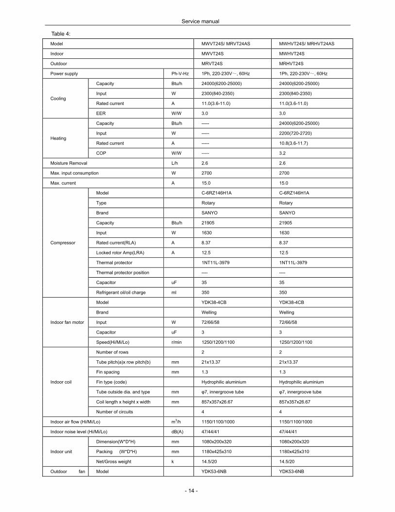
Table 4:
Model MWVT24S/ MRVT24AS MWHVT24S/ MRHVT24AS
Indoor MWVT24S MWHVT24S
Outdoor MRVT24S MRHVT24S
Power supply Ph-V-Hz 1Ph, 220-230V~, 60Hz 1Ph, 220-230V~, 60Hz
Cooling
Capacity Btu/h 24000(6200-25000) 24000(6200-25000)
Input W 2300(840-2350) 2300(840-2350)
Rated current A 11.0(3.6-11.0) 11.0(3.6-11.0)
EER W/W 3.0 3.0
Heating
Capacity Btu/h ----- 24000(6200-25000)
Input W ----- 2200(720-2720)
Rated current A ----- 10.8(3.6-11.7)
COP W/W ----- 3.2
Moisture Removal L/h 2.6 2.6
Max. input consumption W 2700 2700
Max. current A 15.0 15.0
Compressor
Model C-6RZ146H1A C-6RZ146H1A
Type Rotary Rotary
Brand SANYO SANYO
Capacity Btu/h 21905 21905
Input W 1630 1630
Rated current(RLA) A 8.37 8.37
Locked rotor Amp(LRA) A 12.5 12.5
Thermal protector 1NT11L-3979 1NT11L-3979
Thermal protector position ---- ----
Capacitor uF 35 35
Refrigerant oil/oil charge ml 350 350
Indoor fan motor
Model YDK38-4CB YDK38-4CB
Brand Welling Welling
Input W 72/66/58 72/66/58
Capacitor uF 3 3
Speed(Hi/Mi/Lo) r/min 1250/1200/1100 1250/1200/1100
Indoor coil
Number of rows 2 2
Tube pitch(a)x row pitch(b) mm 21x13.37 21x13.37
Fin spacing mm 1.3 1.3
Fin type (code) Hydrophilic aluminium Hydrophilic aluminium
Tube outside dia. and type mm φ7, innergroove tube φ7, innergroove tube
Coil length x height x width mm 857x357x26.67 857x357x26.67
Number of circuits 4 4
Indoor air flow (Hi/Mi/Lo) m3/h 1150/1100/1000 1150/1100/1000
Indoor noise level (Hi/Mi/Lo) dB(A) 47/44/41 47/44/41
Indoor unit
Dimension(W*D*H) mm 1080x200x320 1080x200x320
Packing (W*D*H) mm 1180x425x310 1180x425x310
Net/Gross weight k 14.5/20 14.5/20
Outdoor fan Model YDK53-6NB YDK53-6NB

Service manual
- 15 -
motor Brand Welling Welling
Input W 157.3/93.8 157.3/93.8
Capacitor uF 2.5 2.5
Speed r/min 790/540 790/540
Outdoor coil
Number of rows 2.5 2.5
Tube pitch(a)x row pitch(b) mm 21x13.37 21x13.37
Fin spacing mm 1.4 1.4
Fin type (code) Unhydrophilic aluminium Hydrophilic aluminium
Tube outside dia. and type mm φ7, innergroove tube φ7, innergroove tube
Coil length x height x width mm 773x798x26.74+392x798x13.37 773x798x26.74+392x798x13.37
Number of circuits 6 6
Outdoor air flow m3/h 3500 3500
Outdoor noise level dB(A) 60 60
Outdoor unit
Dimension(W*D*H) mm 895x330x860 895x330x860
Packing (W*D*H) mm 1043x395x915 1043x395x915
Net/Gross weight kg 63.5/67.5 63.5/67.5
Refrigerant type g R410A/1850g R410A/1900g
Design pressure MPa 4.2/1.5 4.2/1.5
Refrigerant
piping
Liquid side/ Gas side mm(inch
) φ9.53/φ16.0(3/8"/5/8") φ9.53/φ16.0(3/8"/5/8")
Max. refrigerant pipe length m 25 25
Max. difference in level m 10 10
Connection wiring
Plug type
Thermostat type Remote control Remote control
Operation temp 17-30 17-30
Ambient temp (cooling/heating) 18-50/---- 18-50/-15-34
Application area m2 35-58 35-58
Qty’per 20’ /40’ /40'HQ 46/106/117 46/106/117
Note:
The noise date is base on hemi-anechoic chamber, during actual operation; these values are normally somewhat different
as a result of ambient condition.
The above design and specifications are subject to change without prior notice for product improvement.

Service manual
- 16 -
5 Refrigerant cycle diagram
Cooling only mode
Heat pump mode

Service manual
- 17 -
6 Operation limits
Mode
Temperature Cooling operation Heating operation Drying operation
Room temperature 17~ 32 17~ 27 10~ 32
Outdoor temperature
18~50
15~ 34 10~ 50 (-15~43:For the models
with low temperature cooling
system)
7 Wiring diagram
MWVT09S; MWHVT09S; MWVT12S; MWHVT12S; MWVT18S; MWHVT18S Indoor unit:
Service manual
- 18 -
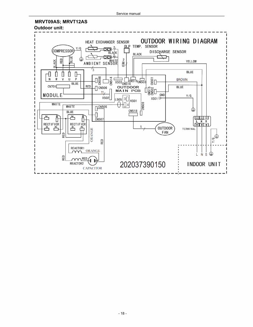
MRVT09AS; MRVT12AS Outdoor unit:

Service manual
- 19 -
MRHVT09AS, MRHVT12AS Outdoor unit:

Service manual
- 20 -
MRVT18AS; MRHVT18AS Outdoor unit:

Service manual
- 21 -
MWVT24S; MWHVT24S Indoor unit:
Service manual
- 22 -
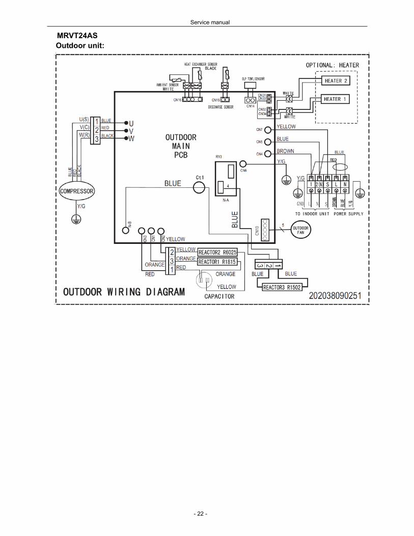
MRVT24AS Outdoor unit:
Service manual
- 23 -
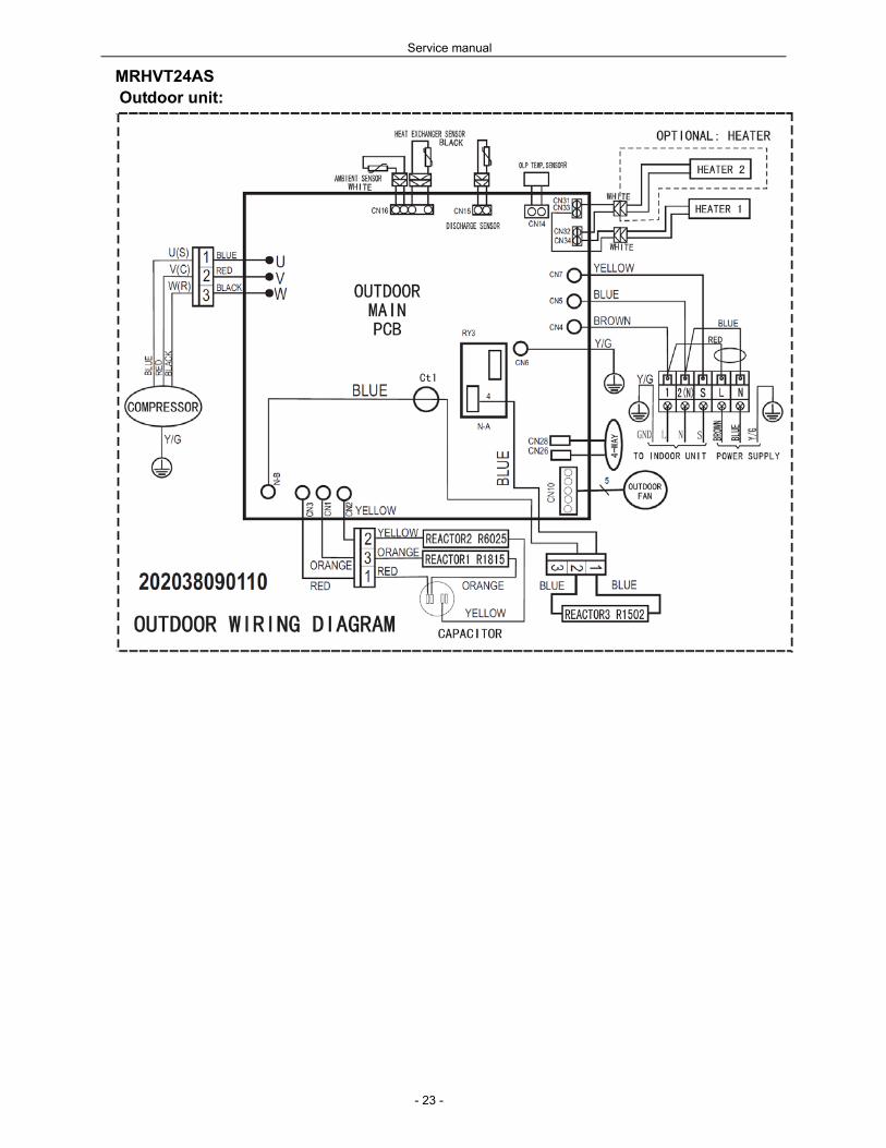
MRHVT24AS Outdoor unit:
Service manual
- 24 -
8 Installation details
8.1 Wrench torque sheet for installation
Torque
mm inch Kg.m
φ6.35 1/4 1.8
φ9.52 3/8 4.2
φ12.7 1/2 5.5
φ15.88 5/8 6.6
φ19.05 3/4 6.6
Outside diameter
8.2 Connecting the cables
The power cord of connect should be selected according to the following specifications sheet.
Grade
Unit 9K 12K 18K 24K
mm2 1.5 1.5 2.5 2.5
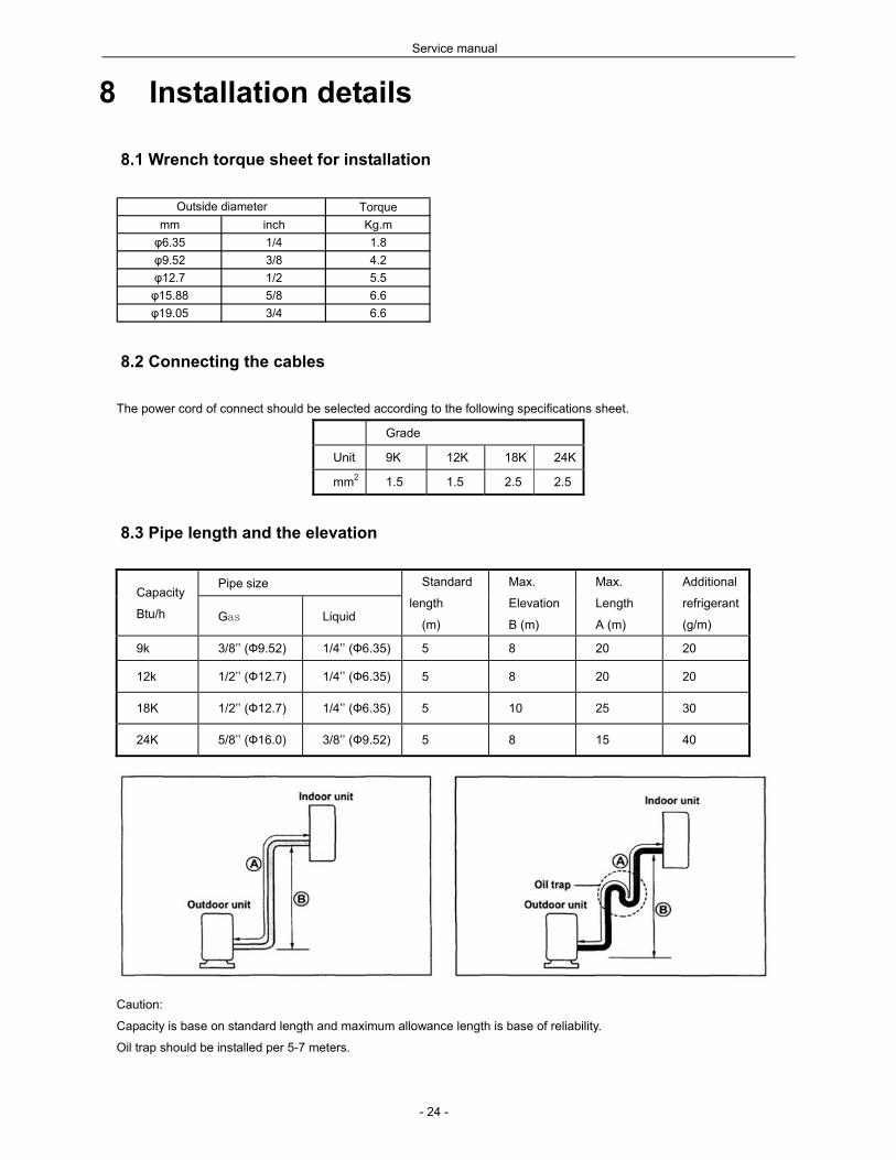
8.3 Pipe length and the elevation
Capacity
Btu/h
Pipe size Standard
length
(m)
Max.
Elevation
B (m)
Max.
Length
A (m)
Additional
refrigerant
(g/m) Gas Liquid
9k 3/8’’ (Ф9.52) 1/4’’ (Ф6.35) 5 8 20 20
12k 1/2’’ (Ф12.7) 1/4’’ (Ф6.35) 5 8 20 20
18K 1/2’’ (Ф12.7) 1/4’’ (Ф6.35) 5 10 25 30
24K 5/8’’ (Ф16.0) 3/8’’ (Ф9.52) 5 8 15 40
Caution:
Capacity is base on standard length and maximum allowance length is base of reliability.
Oil trap should be installed per 5-7 meters.

Service manual
- 25 -
8.4 Air purging of the piping and indoor unit
Required tools:
Hexagonal wrench; adjustable wrench; torque wrenches, wrench to hold the joints and gas leak detector.
Note:
The air in the indoor unit and in the piping must be purged. If air remains in the refrigeration piping, it will affect the
compressor, reduce the cooling capacity, and could lead to a malfunction of unit.
Be sure, using a torque wrench to tighten the service port cap (after using the service port), so that it prevents the gas
leakage from the refrigeration cycle.
Procedure:
1. Recheck the piping connections.
2. Open the valve stem of the 2-way valve counterclockwise approximately 90’, wait 10 seconds, and then set it to
closed position.
Be sure to use a hexagonal wrench to operate the valve stem
3. Check for gas leakage.
Check the flare connection for gas leakage
4. Purge the air from the system.
5. Set the 2-way valve to the open position and remove the cap from the 3-way valve’s service port.
6. Using the hexagonal wrench to press the valve core pin, discharge for three seconds and then wait for one minute.
7. Use torque wrench to tighten the service port cap to a torque of 1.8 kg.m. (18n.m)
8. Set the 3-way valve to the opened position.
9. Mounted the valve stem nuts to the 2-way and 3-way valves.
10. Check for gas leakage.
11. At this time, especially check for gas leakage from the 2-way and 3-way stem nuts, and from the service port.
Caution:
If gas leakage is discovered in step (3) above, take the following measures.
If the leaks stop when the piping connections are tightened further, continue working from step (4).
If the gas leaks do not stop when the connections are retightened, repair the location of the leak, discharge all of the gas
through the service port, and then recharge with the specified amount of gas from a gas cylinder.
Service manual
- 26 -
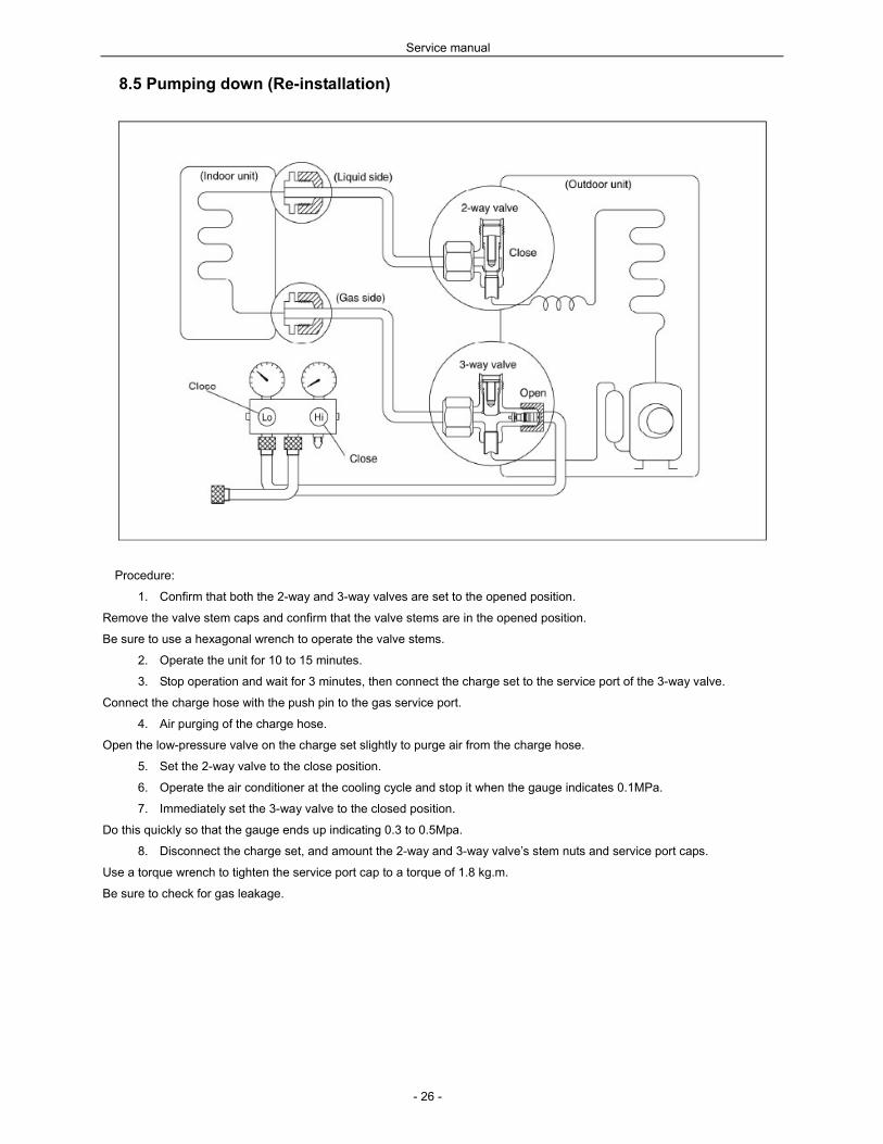
8.5 Pumping down (Re-installation)
Procedure:
1. Confirm that both the 2-way and 3-way valves are set to the opened position.
Remove the valve stem caps and confirm that the valve stems are in the opened position.
Be sure to use a hexagonal wrench to operate the valve stems.
2. Operate the unit for 10 to 15 minutes.
3. Stop operation and wait for 3 minutes, then connect the charge set to the service port of the 3-way valve.
Connect the charge hose with the push pin to the gas service port.
4. Air purging of the charge hose.
Open the low-pressure valve on the charge set slightly to purge air from the charge hose.
5. Set the 2-way valve to the close position.
6. Operate the air conditioner at the cooling cycle and stop it when the gauge indicates 0.1MPa.
7. Immediately set the 3-way valve to the closed position.
Do this quickly so that the gauge ends up indicating 0.3 to 0.5Mpa.
8. Disconnect the charge set, and amount the 2-way and 3-way valve’s stem nuts and service port caps.
Use a torque wrench to tighten the service port cap to a torque of 1.8 kg.m.
Be sure to check for gas leakage.
Service manual
- 27 -
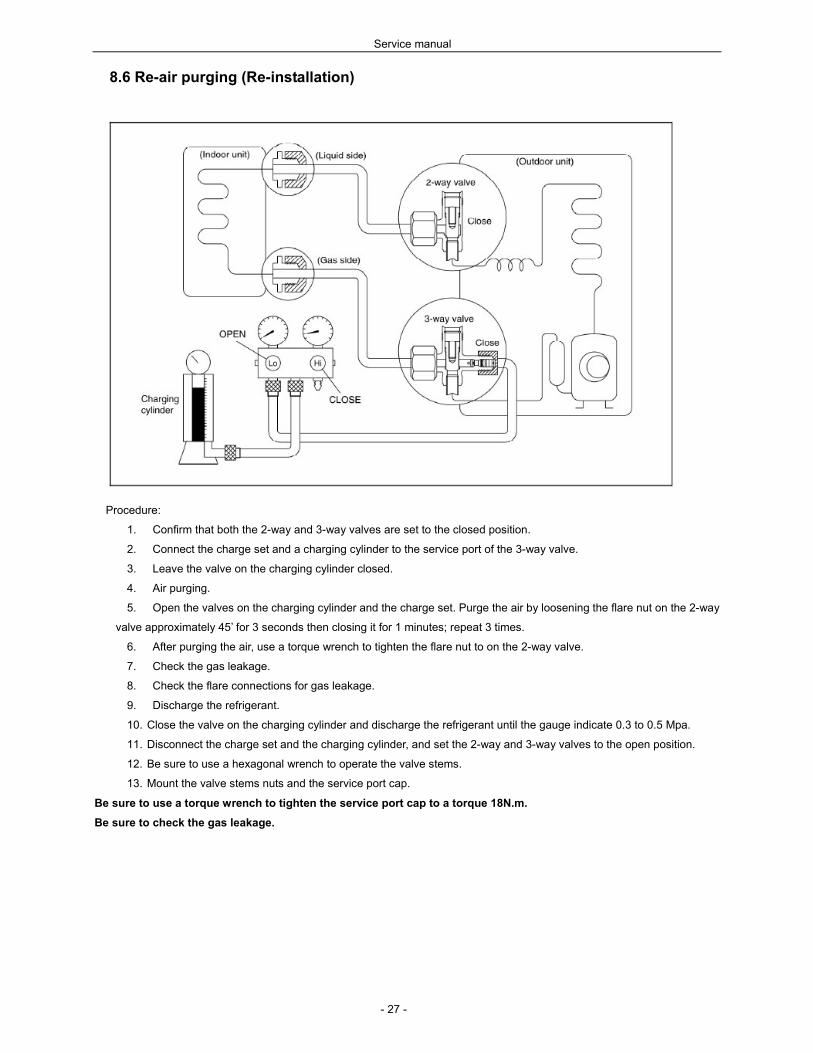
8.6 Re-air purging (Re-installation)
Procedure:
1. Confirm that both the 2-way and 3-way valves are set to the closed position.
2. Connect the charge set and a charging cylinder to the service port of the 3-way valve.
3. Leave the valve on the charging cylinder closed.
4. Air purging.
5. Open the valves on the charging cylinder and the charge set. Purge the air by loosening the flare nut on the 2-way
valve approximately 45’ for 3 seconds then closing it for 1 minutes; repeat 3 times.
6. After purging the air, use a torque wrench to tighten the flare nut to on the 2-way valve.
7. Check the gas leakage.
8. Check the flare connections for gas leakage.
9. Discharge the refrigerant.
10. Close the valve on the charging cylinder and discharge the refrigerant until the gauge indicate 0.3 to 0.5 Mpa.
11. Disconnect the charge set and the charging cylinder, and set the 2-way and 3-way valves to the open position.
12. Be sure to use a hexagonal wrench to operate the valve stems.
13. Mount the valve stems nuts and the service port cap.
Be sure to use a torque wrench to tighten the service port cap to a torque 18N.m.
Be sure to check the gas leakage.

Service manual
- 28 -
8.7 Balance refrigerant of the 2-way, 3-way valves
Procedure:
1. Confirm that both the 2-way and 3-way valves are set to the open position.
2. Connect the charge set to the 3-way valve’s service port.
Leave the valve on the charge set closed.
Connect the charge hose with the push pin to the service port.
3. Open the valves (Low side) on the charge set and discharge the refrigerant until the gauge indicates 0.05 to 0.1
Mpa.
If there is no air in the refrigeration cycle [the pressure when the air conditioner is not running is higher than 0.1Mpa, discharge
the refrigerant until the gauge indicates 0.05 to 0.1 Mpa. If this is the case, it will not be necessary to apply a evacuation.
Discharge the refrigeration gradually; if it is discharged too suddenly, the refrigeration oil sill be discharged.

Service manual
- 29 -
8.8 Evacuation
Procedure:
1. Connect the vacuum pump to the charge set’s centre hose.
2. Evacuation for approximately one hour.
Confirm that the gauge needle has moved toward -0.1 Mpa (-76 cmHg) [vacuum of 4 mmHg or less].
3. Close the valve (Low side) on the charge set, turn off the vacuum pump, and confirm that the gauge needle does
not move (approximately 5 minutes after turning off the vacuum pump).
4. Disconnect the charge hose from the vacuum pump.
Vacuum pump oil, if the vacuum pump oil becomes dirty or depleted, replenish as needle.
Service manual
- 30 -
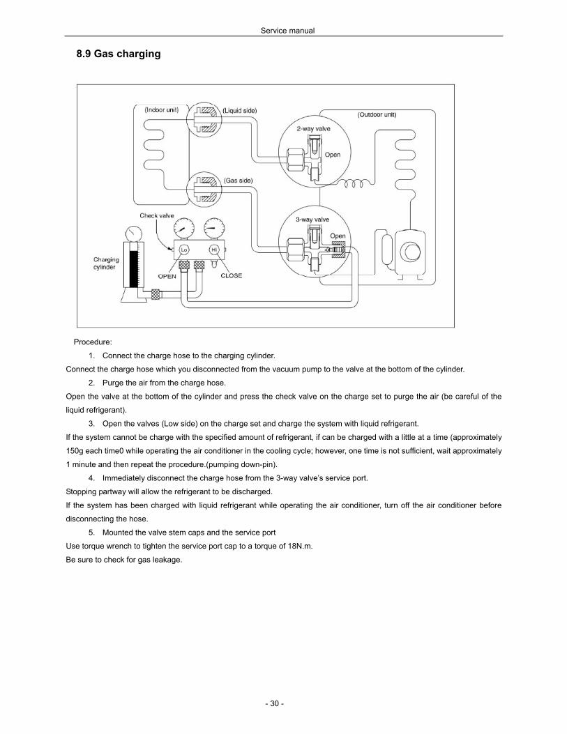
8.9 Gas charging
Procedure:
1. Connect the charge hose to the charging cylinder.
Connect the charge hose which you disconnected from the vacuum pump to the valve at the bottom of the cylinder.
2. Purge the air from the charge hose.
Open the valve at the bottom of the cylinder and press the check valve on the charge set to purge the air (be careful of the
liquid refrigerant).
3. Open the valves (Low side) on the charge set and charge the system with liquid refrigerant.
If the system cannot be charge with the specified amount of refrigerant, if can be charged with a little at a time (approximately
150g each time0 while operating the air conditioner in the cooling cycle; however, one time is not sufficient, wait approximately
1 minute and then repeat the procedure.(pumping down-pin).
4. Immediately disconnect the charge hose from the 3-way valve’s service port.
Stopping partway will allow the refrigerant to be discharged.
If the system has been charged with liquid refrigerant while operating the air conditioner, turn off the air conditioner before
disconnecting the hose.
5. Mounted the valve stem caps and the service port
Use torque wrench to tighten the service port cap to a torque of 18N.m.
Be sure to check for gas leakage.
Service manual
- 31 -
9 Electronic function
9.1 Abbreviation
T1: Indoor ambient temperature
T2: Pipe temperature of indoor heat exchanger
T3: Pipe temperature of outdoor heat exchanger
T4: Outdoor ambient temperature
9.2 Display function
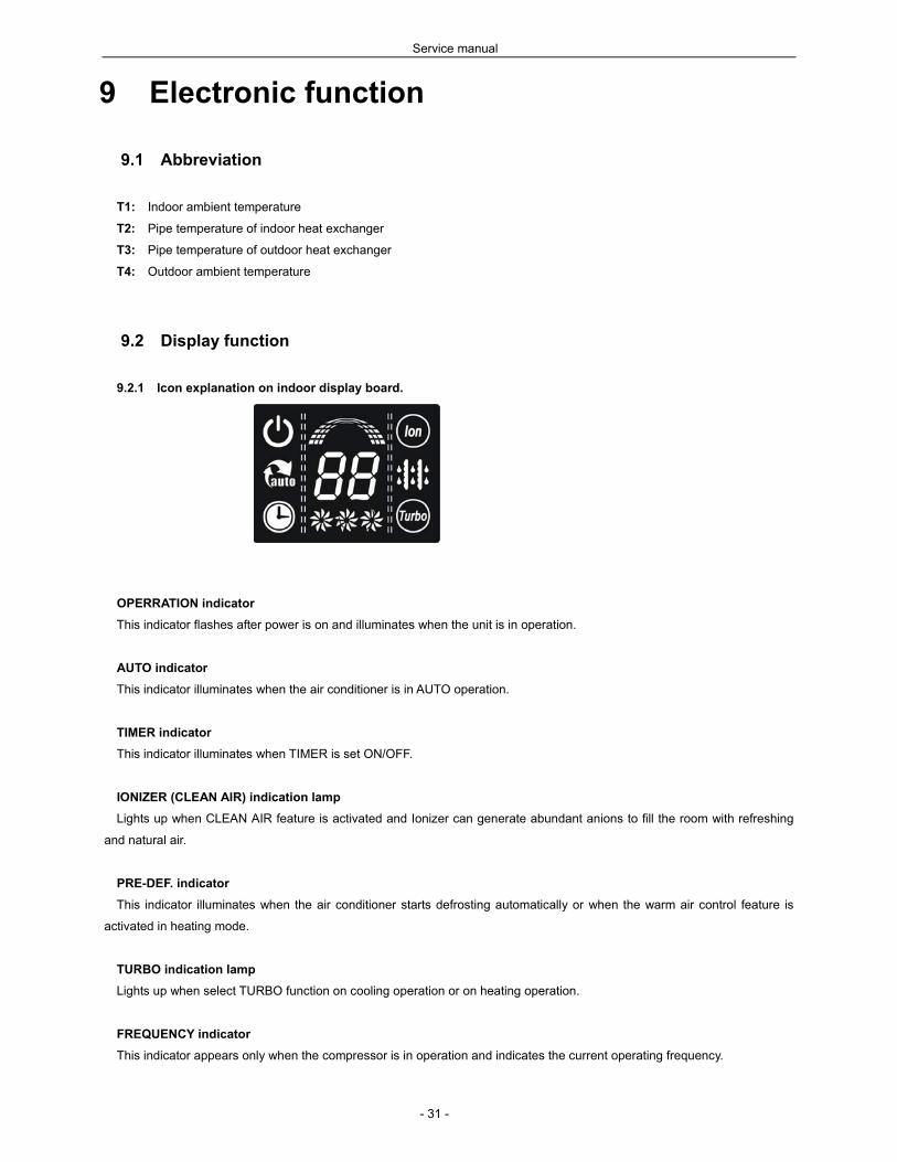
9.2.1 Icon explanation on indoor display board.
OPERRATION indicator
This indicator flashes after power is on and illuminates when the unit is in operation.
AUTO indicator
This indicator illuminates when the air conditioner is in AUTO operation.
TIMER indicator
This indicator illuminates when TIMER is set ON/OFF.
IONIZER (CLEAN AIR) indication lamp
Lights up when CLEAN AIR feature is activated and Ionizer can generate abundant anions to fill the room with refreshing
and natural air.
PRE-DEF. indicator
This indicator illuminates when the air conditioner starts defrosting automatically or when the warm air control feature is
activated in heating mode.
TURBO indication lamp
Lights up when select TURBO function on cooling operation or on heating operation.
FREQUENCY indicator
This indicator appears only when the compressor is in operation and indicates the current operating frequency.

Service manual
- 32 -
TEMPERATURE indicator
Usually it displays the temperature settings. When change the setting temperature, this indicator begins to flash, and stops
20 seconds later. It displays the room temperature when the air conditioner is in FAN only operation. When the unit stops
operation, it returns to original factory settings. The temperature indicator area will display “SC” when the self clean function is
started.
It also displays the malfunction code or protection code.
FAN SPEED indication lamp
Displays the selected fan speed: AUTO (nothing) and three fan speed levels: LOW, MED and HIGH.
9.2.2 LED display control function.
Pressing “LED display” button on remote controller will turn off all displays on indoor unit, when pressing once again, all
displays will resume.
9.2.3 Display function in outdoor unit.
9.3 Protection
9.3.1 Three Minutes Delay at restart for compressor.
9.3.2 Temperature protection of compressor top.
9.3.3 If the temperature of compressor top is too high(higher than 115 and the Over-load Protector is cut, the units stop.
When the Over-load Protector restore and close(lower than 100), the compressor will restart( in this case the compressor is
restricted by Three Minutes Delay protection.
9.3.4 Temperature protection of compressor exhaust.
If the exhaust temp. of compressor is higher than 115 and lasts for 5 seconds, the compressor stops and does
not resume until the exhaust temp. is lower than 90.
9.3.5 Inverter module Protection, Inverter module Protection itself has a protection function against current, voltage and
temperature. If these protections happened, the corresponding code will display on indoor unit LED.
9.3.6 Sensor protection at open circuit and breaking disconnection
9.3.7 Fan Speed is out of control. When Indoor Fan Speed is too low (lower than 300RPM for 60 seconds), the unit stops
and LED displays failure information and can’t return to normal operation automatically.
9.3.8 Cross Zero signal error warning. If there are 20 alternations of Cross Zero signals are incorrect, the unit stops and
LED displays failure information. After resuming, the motor rotates again. The spacing of Cross Zero signal is 6-13ms.
9.3.9 Indoor fan delayed open function
9.3.10 For all modes, when the units are turned on, the indoor fan can operate 10 seconds after the action of louver.
9.3.11 Compressor preheating function.
Preheating permitting condition:
If T4(outdoor ambient temperature)<3 and the machine connects to power supply newly or if T4<3 and
compressor has stopped for over 3 hours, the compressor heating cable will work.
Preheating mode:
A weak current flows through the coil of compressor from the wiring terminal of compressor, then the
compressor is heated without operation.
Preheating release condition:
If T4>5 or user turns on the machine and compressor runs, preheating function will stop.
9.3.12 Compressor heating cable
If outdoor temperature is lower than 5, the compressor heating cable begins to work. If outdoor temperature is higher than
15, the compressor heating cable stops working.

Service manual
- 33 -
9.4 Fan-Only Mode
9.4.1 Temperature setting function is disabled, and no setting temperature display.
9.4.2 In this mode, the action of louver is the same as in cooling mode.
9.4.3 The action of auto fan in fan-only mode is the same as auto fan in cooling mode with 24 setting temperature.
9.5 Cooling Mode
9.5.1 After starting, the operation frequency of compressor submits to following rule.
When the machine is running and ∆T(=room temp. – setting temp.) changes, the frequency of compressor will rise or
descend a grade (7 minutes after starting).
After starting, if ∆T stays in a zone for 3 minutes, the frequency will change as follow:
Zone A : Current frequency rise a grade till the maximum grade F8.
Zone B: Keep the current frequency of compressor.
Zone C: Descend the current frequency of compressor until F1.
Zone D: Compressor stops after running as the minimum frequency F1 for 60 minutes or ∆T is less than -2.
9.5.2 Indoor heat exchanger anti-freezing function.
If T2 is lower than 0, the compressor stops and resumes when T2>5.
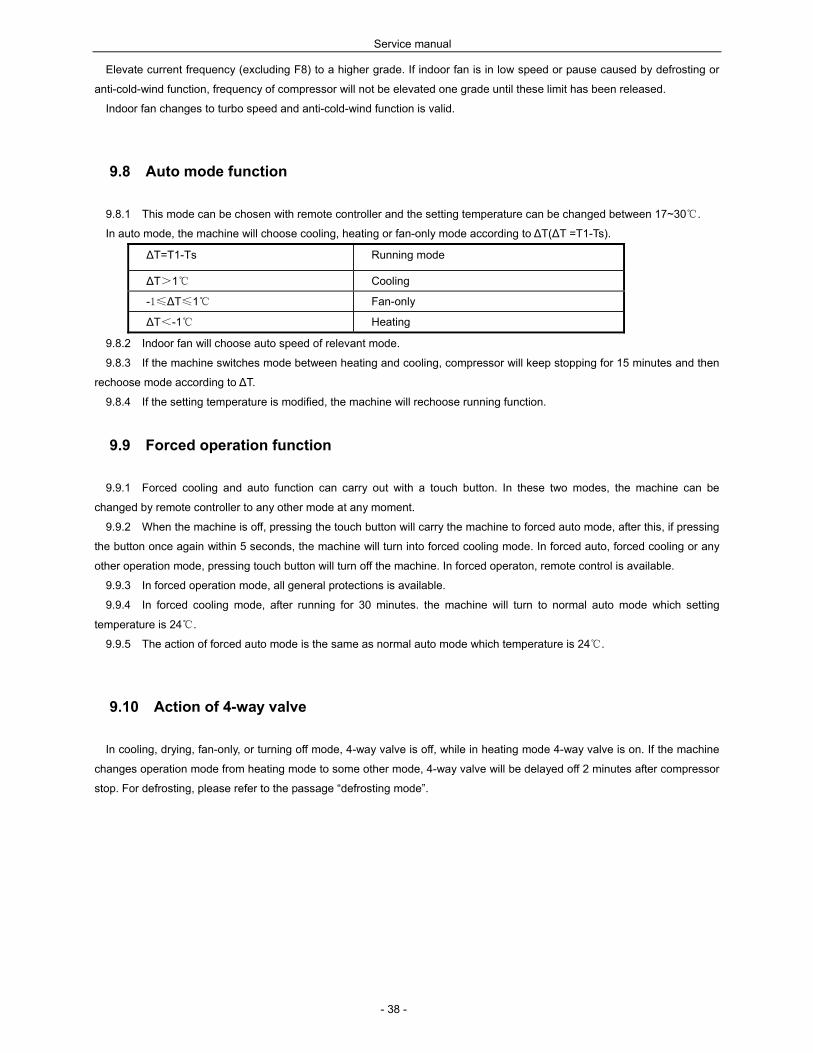
9.5.3 Outdoor unit current control in cooling mode(refer to the parameter table)
Remark:
D -1.
B 1.0
-0.
0.5
1.5
C
T1
– 2
4
medium
3.5
3.0
1.5
1.0
high
low
I3COOL
I2COOL
I1COOL
comp. pause
freq. descends if curr. rises;
freq. remains if curr. descends
running normally
ou
tdo
or
unit
curr
en
t
∆T
=(r
oo
m t
em
p)
– (
setti
ng
A
Service manual
- 34 -
I1COOL I2COOL I3COOL
9K Model 5.0 A 6.5 A 7.5 A
12K Model 5.5A 7.0 A 7.8 A
18K Model 9.5 A 10.5 A 13A
24K Model 11 A 12A 13 A
9.5.4 Rating capacity test function
1) Set the indoor unit with remote controller as: high fan, 17 in cooling mode, then press “TURBO” button on controller 6
times or more within 10 seconds(make sure indoor unit receives these signals), the machine will turn into rating capacity test
mode, the buzzer will make a “di” sound for 2 seconds continuously. Also, indoor fan will change to rating speed, the frequency
of compressor will be fixed as rating value. Any condition of above is not satisfied, the machine can not be turned into rating
capacity test mode.
2) The machine will quit from the rating capacity test mode if running for 5 hours or changing fan speed or setting
temperature.
9.5.5 Turbo function(press the “TURBO” button on remote controller)
Elevate current frequency to a higher grade.
Indoor fan turns to turbo speed.
After running for 30 minutes the machine will turn back to previous setting mode.
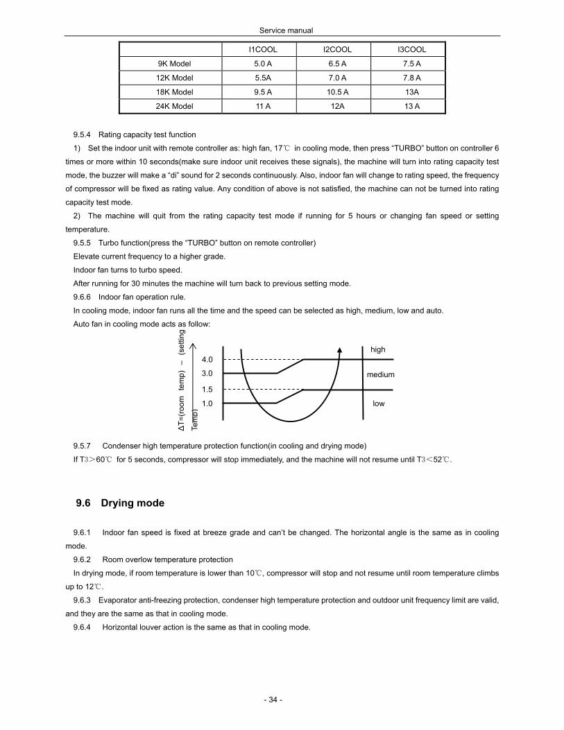
9.6.6 Indoor fan operation rule.
In cooling mode, indoor fan runs all the time and the speed can be selected as high, medium, low and auto.
Auto fan in cooling mode acts as follow:
9.5.7 Condenser high temperature protection function(in cooling and drying mode)
If T3>60 for 5 seconds, compressor will stop immediately, and the machine will not resume until T3<52.
9.6 Drying mode
9.6.1 Indoor fan speed is fixed at breeze grade and can’t be changed. The horizontal angle is the same as in cooling
mode.
9.6.2 Room overlow temperature protection
In drying mode, if room temperature is lower than 10, compressor will stop and not resume until room temperature climbs
up to 12.
9.6.3 Evaporator anti-freezing protection, condenser high temperature protection and outdoor unit frequency limit are valid,
and they are the same as that in cooling mode.
9.6.4 Horizontal louver action is the same as that in cooling mode.
∆T
=(r
oom
te
mp
) –
(set
ting
Tem
p)
medium
4.0
3.0
1.5
1.0
high
low
Service manual
- 35 -
9.7 Heating mode
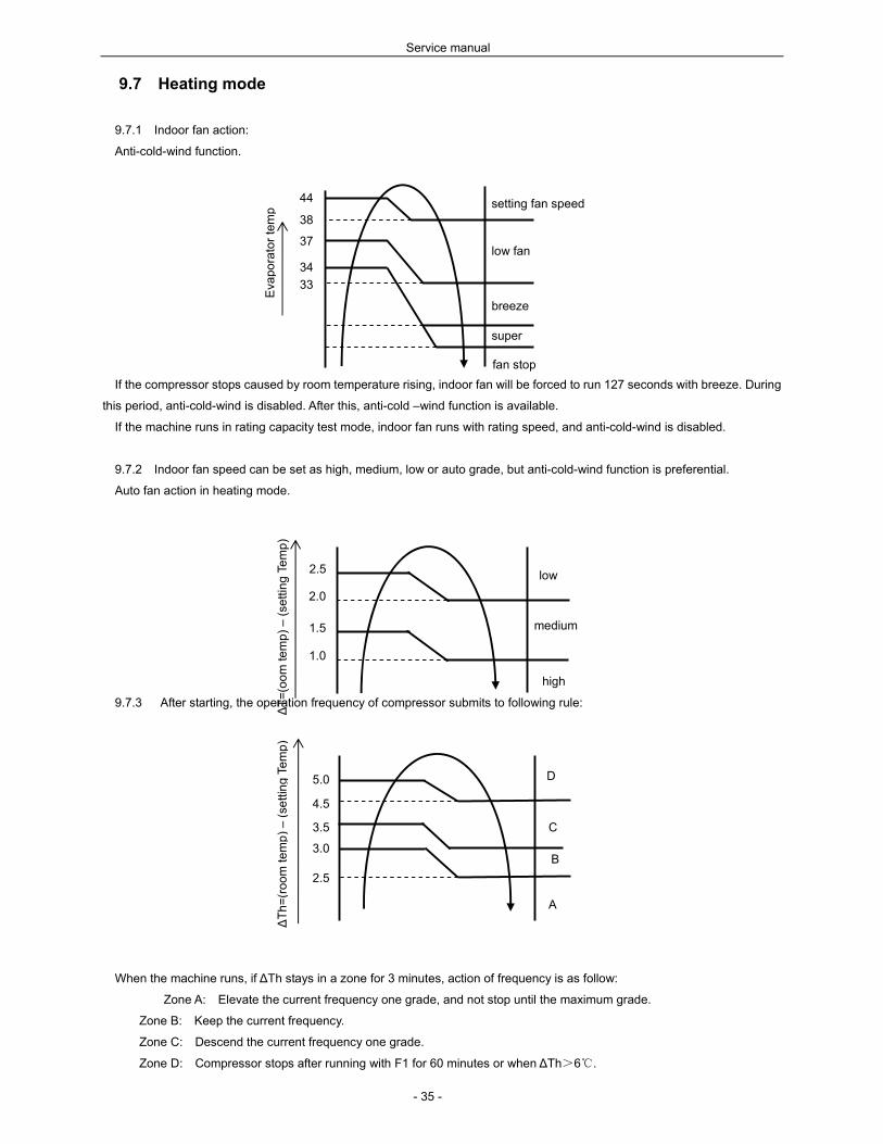
9.7.1 Indoor fan action:
Anti-cold-wind function.
If the compressor stops caused by room temperature rising, indoor fan will be forced to run 127 seconds with breeze. During
this period, anti-cold-wind is disabled. After this, anti-cold –wind function is available.
If the machine runs in rating capacity test mode, indoor fan runs with rating speed, and anti-cold-wind is disabled.
9.7.2 Indoor fan speed can be set as high, medium, low or auto grade, but anti-cold-wind function is preferential.
Auto fan action in heating mode.
9.7.3 After starting, the operation frequency of compressor submits to following rule:
When the machine runs, if ∆Th stays in a zone for 3 minutes, action of frequency is as follow:
Zone A: Elevate the current frequency one grade, and not stop until the maximum grade.
Zone B: Keep the current frequency.
Zone C: Descend the current frequency one grade.
Zone D: Compressor stops after running with F1 for 60 minutes or when ∆Th>6.
A
5.0
4.5
3.0
2.5
D
C
∆T
h=
(ro
om
tem
p)
– (
setti
ng
Te
mp
)
3.5
B
44
38
37
34
33
setting fan speed
low fan
breeze
super
fan stop
Eva
pora
tor
tem
p
∆T
=(o
om
tem
p)
– (
setti
ng
Te
mp
)
medium
2.5
2.0
1.5
1.0
low
high

Service manual
- 36 -
9.7.4 Outdoor unit current control in heating mode.
Remark:
I1HEAT I2 HEAT I3 HEAT
9K Model 5.5 A 7.0 A 8.0A
12K Model 5.5 A 7.0 A 8.0 A
18K Model 9.5 A 10.5A 13A
24K Model 11 A 12A 13 A
9.7.5 Indoor heat exchanger high temperature protection.
If T2>60, the compressor will stop and not resume until T2<48.
Defrosting mode.
Condition of defrosting.
Condition 1: If T4>0,
When the units are running, if the following two items are satisfied the units start defrosting:
The units runs with T3<3 for 40 minutes and T3 keeps lower than -6 for more than 3 minutes.
The units runs with T3<3 for 80 minutes and T3 keeps lower than -4 for more than 3 minutes.
Condition 2: If T4<0,
The program judges according to the condition 1, if the two items are satisfied, then judges if T2 has
descended for more than 5, if it has the machine starts defrosting, or continues to judge T2 and will
not defrost until T2 drops more than 5.
Condition 3: No matter what value T4 is, if the machine runs with T3<3 for more than 120 minutes and T3 keeps lower
than -2 for more than 3 minutes, the machine will defrost, no matter if T2 drops for more than 5 or not.
Condition of ending defrosting.
If any one of following items is satisfied, defrosting will finish and the machine will turn to normal heating
mode.
T3 rises to be higher than 12.
T3 rises to be higher than 8 and remains for 80 seconds.
The machine has run for 10 minutes in defrosting.
I3HEAT
I2HEAT
I1HEAT
comp. pause
freq. descends if curr. rises;
freq. remains if curr. descends
running normally
ou
tdo
or
un
it

Service manual
- 37 -
9.7.7 Defrosting action.
For 9K, 12K, 18K:
For 24K:
9.7.8 Rating capacity test function.
Set the indoor unit with remote controller as: high fan, 30 in heating mode, then press “TURBO” button on controller 6
times or more within 10 seconds(make sure indoor unit receives these signals), the machine will turn into rating capacity test
mode, the buzzer will make a “di” sound for 2 seconds continuously. Also, indoor fan will change to rating speed, the frequency
of compressor will be fixed as rating value. Any condition of above is not satisfied, the machine can not be turned into rating
capacity test mode.
The machine will quit from the rating capacity test mode if running for 5 hours or changing fan speed or setting temperature.
9.7.9 Turbo function in heating mode. (press the “TURBO” button on remote controller)
on
off
on
off
on
off
on
off
compressor
4-way valve
outdoor fan
indoor fan
indoor fan breeze 60s
70s
no longer than 10 minutes 30s
F8
on
off
on
off
on
off
on
off
compressor
4-way valve
outdoor fan
indoor fan
indoor fan breeze 10s 90s
100s
no longer than 10 minutes 30s
F8
Service manual
- 38 -
Elevate current frequency (excluding F8) to a higher grade. If indoor fan is in low speed or pause caused by defrosting or
anti-cold-wind function, frequency of compressor will not be elevated one grade until these limit has been released.
Indoor fan changes to turbo speed and anti-cold-wind function is valid.
9.8 Auto mode function
9.8.1 This mode can be chosen with remote controller and the setting temperature can be changed between 17~30.
In auto mode, the machine will choose cooling, heating or fan-only mode according to ∆T(∆T =T1-Ts).
∆T=T1-Ts Running mode
∆T>1 Cooling
-1≤∆T≤1 Fan-only
∆T<-1 Heating
9.8.2 Indoor fan will choose auto speed of relevant mode.
9.8.3 If the machine switches mode between heating and cooling, compressor will keep stopping for 15 minutes and then
rechoose mode according to ∆T.
9.8.4 If the setting temperature is modified, the machine will rechoose running function.
9.9 Forced operation function
9.9.1 Forced cooling and auto function can carry out with a touch button. In these two modes, the machine can be
changed by remote controller to any other mode at any moment.
9.9.2 When the machine is off, pressing the touch button will carry the machine to forced auto mode, after this, if pressing
the button once again within 5 seconds, the machine will turn into forced cooling mode. In forced auto, forced cooling or any
other operation mode, pressing touch button will turn off the machine. In forced operaton, remote control is available.
9.9.3 In forced operation mode, all general protections is available.
9.9.4 In forced cooling mode, after running for 30 minutes. the machine will turn to normal auto mode which setting
temperature is 24.
9.9.5 The action of forced auto mode is the same as normal auto mode which temperature is 24.
9.10 Action of 4-way valve
In cooling, drying, fan-only, or turning off mode, 4-way valve is off, while in heating mode 4-way valve is on. If the machine
changes operation mode from heating mode to some other mode, 4-way valve will be delayed off 2 minutes after compressor
stop. For defrosting, please refer to the passage “defrosting mode”.

Service manual
- 39 -
9.11 Two speeds outdoor fan function
9.11.1 Outdoor fan starts at the same time with compressor, but stops 30 seconds later after compressor stop.
9.11.2 Outdoor fan action in heating mode(including heating in auto mode).
9.11.3 Outdoor fan action in cooling & drying mode(including cooling in auto & forced mode).
Please refer to the pic. above.
9.12 Timer function
9.12.1 Timing range is 24 hours, and the minimum resolution is 15 minutes.
9.12.2 Timer on. After turning off, the machine will turn on automatically when reaching the setting time.
9.12.3 Timer off. After turning on, the machine will turn off automatically when reaching the setting time.
9.12.4 Timer on/off. After turning off, the machine will turn on automatically when reaching the setting “on” time, and then
turn off automatically when reaching the setting “off” time.
9.12.5 Timer off/on. After turning on, the machine will turn off automatically when reaching the setting “off” time, and then
turn on automatically when reaching the setting “on” time.
9.12.6 The tolerance of Timer is 1 minute per hour.
9.13 Sleep function mode
9.13.1 Operation time in sleep mode is 7 hours. After 7 hours the machine quits this mode and turns off.
9.13.2 In cooling, heating or auto mode sleep function is available.
9.13.3 Operation process in sleep mode is as follow:
After pressing ECONOMIC or SLEEP button on controller, the machine will turn into sleep mode.
When cooling, the setting temperature rises 1(be lower than 30) every one hour, 2 hour later the rising stops and
indoor fan is fixed as low speed.
When heating, the setting temperature descends 1(be lower than 30) every one hour, 2 hour later the descending
stops and indoor fan is fixed as low speed, and anti-cold-wind is available.
9.13.4 If user uses timer on function in sleep mode, sleep function will pause and not resume until reaches the setting on
time.
9.13.5 When user uses timer off function in sleep mode(or sleep function in timer off mode), if the timing time is less than 7
hours, sleep function will be cancelled when reaching the setting time. If the timing time is more than 7 hours, the machine will
not stop until reaches the setting off time in sleep mode.
Outdoor fan action in cooling & drying
mode
17
15
ou
tdo
or
low
high
ou
tdo
or
fan
sp
eed
Outdoor fan action in heating mode
(including heating in auto mode).
22
20
ou
tdo
or
high
low
ou
tdo
or
fan
spe
ed

Service manual
- 40 -
9.14 Auto-Restart function
The indoor unit is equipped with auto-restart function, which is carried out through an auto-restart module. In case of a
sudden power failure, the module restores the setting conditions before the power failure. The unit will resume the previous
operation setting (including Mode, Fan speed, Temperature, ON/OFF) automatically after 3 minutes when power returns.
9.15 Automatic panel function
The automatic panel is forced to turn to the closing direction at an angle of 50°when the unit is getting through the power,
and this action is not affected by any signal from remote controller.
When the unit is turned on, the panel is opened automatically at an angle of 50°, then the horizontal louver will be opened.
When the unit is turned off, the panel is closed automatically at an angle of 50°, then the horizontal louver will be closed.
If the panel needs moving when the horizontal louver is in action, the unit will stop the horizontal louver and then carry out
the action of the panel. After ending the action of the panel, the horizontal louver will continue its action.
9.16 Ionizer (Clean Air) function
Clean Air function is available only when the aircon is on, and it’s controlled through remote controller..
After the aircon being turned on, the Clean Air function is switched on when the aircon receives FRESH CODE at first time,
and ionizer is switched off when the aircon receives the CODE again. It’s a circle.
After starting the Clean Air function, the ionizer can work only when the indoor fan motor is running. If the indoor fan motor is
off, the ionizer also stops working, even though the Clean Air function is available.
Switching the running mode will not stop the ionizer. When turning off the aircon, the ionizer is also turned off.
9.17 Self-clean function
1) Self-clean function is chosen through wire jumper J2 in indoor PCB, it’s available when the unit has detected that J2 is
on after getting through the power.
2) Self-Clean function is available only at cooling (including auto-cooling and turbo) and drying mode, when the user press
down the button ”Self-Clean” on remote controller, the “Self-Clean” icon on LCD screen of indoor unit will keep bright. After
running for 13 minutes in low fan mode, the unit turns into low heating mode(anti-cold wind function is not valid), when the unit
keeps low heating mode for 1 min or evaporator high temp protection occur, it stops and turns into low fan mode and keeps
running for 2 minutes, then quits from Self-Clean function and turns off.
3) When setting the Self-Clean function, the unit has been in Timer or Turbo function, the Timer or Turbo function will be
cancelled and then execute Self-Clean function.
4) When the unit is running Self-Clean function, all functions are not available except swing/air direction/clean air/LED
display, and only receiving “Self-Clean” code again or “turn off” code, the unit can quit from the function.
5) When the unit is running Self-Clean function, all protection functions are valid.

Service manual
- 41 -
9.18 Follow me function
Follow me function is chosen through wire jumper J1 in indoor PCB, it’s available when the unit has detected that J1 is on
after getting through the power.
If the indoor PCB receives the signal which results from pressing the FOLLOW ME button on remote controller, the buzzer
will emit a sound and this indicates the follow me function is initiated. But when the indoor PCB receives signal which sent from
remote controller every 3 minutes, the buzzer will not respond. When the unit is running with follow me function, the PCB will
control the unit according to the temperature from follow me signal, and the temperature collection function of room
temperature sensor will be shielded, but the error detective function of room temperature sensor will be still valid.
When the follow me function is available, the PCB will control the unit according to the room temperature from the remote
controller and the setting temperature, and the action of compressor is as following:
At cooling mode, if TA<TS, compressor is off; If TA≥TS, compressor is on.
At heating mode, if TA>TS, compressor is off; If TA≤TS, compressor is on.
The PCB will take action to the mode change information from remote controller signal, but it will not affected by the setting
temperature.
When the unit is running with follow me function, if the PCB doesn’t receive any signal from remote controller for 7 minutes
or pressing FOLLOW ME button again, the follow me function will be turned off automatically, and the temperature collection
function of room temperature sensor will be available, the PCB will control the unit according to the room temperature detected
from its own room temperature sensor and setting temperature.
9.19 Outdoor chassis heating cable function (optional)
Heating cable is fixed on outdoor chassis to help deicing and to avoid freezing. The heating cable’s power is 85w, rated
voltage is 220V-240V, and is controlled by a thermostat. If outdoor temperature (sensed by outdoor thermostat) is lower than
5, the thermostat closed and the heating cable begins to work. If outdoor temperature is higher than 15, the thermostat
opens and the heating cable will stop working.

Service manual
- 42 -
10 Troubleshooting
Safety
Because of there are capacitors in PCB and relative circuit in outdoor unit, even shut down the power supply,
electricity power still are kept in capacitors, do not forget to discharge the electricity power in capacitor.
Electrolytic Capacitors
(HIGH VOLTAGE! CAUTION!)
Bulb (25-40W)
Service manual
- 43 -
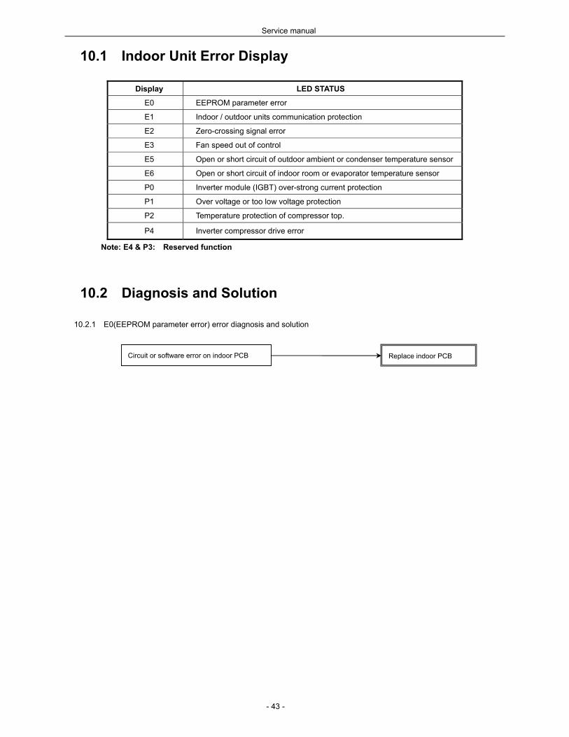
10.1 Indoor Unit Error Display
Display LED STATUS
E0 EEPROM parameter error
E1 Indoor / outdoor units communication protection
E2 Zero-crossing signal error
E3 Fan speed out of control
E5 Open or short circuit of outdoor ambient or condenser temperature sensor
E6 Open or short circuit of indoor room or evaporator temperature sensor
P0 Inverter module (IGBT) over-strong current protection
P1 Over voltage or too low voltage protection
P2 Temperature protection of compressor top.
P4 Inverter compressor drive error
Note: E4 & P3: Reserved function
10.2 Diagnosis and Solution
10.2.1 E0(EEPROM parameter error) error diagnosis and solution
Circuit or software error on indoor PCB Replace indoor PCB
Service manual
- 44 -
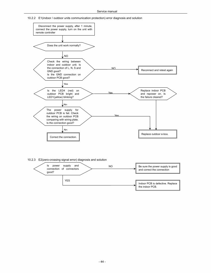
10.2.2 E1(indoor / outdoor units communication protection) error diagnosis and solution
10.2.3 E2(zero-crossing signal error) diagnosis and solution
Disconnect the power supply, after 1 minute, connect the power supply, turn on the unit with remote controller
Does the unit work normally?
Check the wiring between indoor and outdoor unit. Is the connection of L, N, S and GND good? Is the GND connection on outdoor PCB good?
NO
NOReconnect and retest again
Is the LED4 (red) on outdoor PCB bright and LED1(yellow) blinking?
Replace outdoor e-box.
Yes
Yes
The power supply for outdoor PCB is fail. Check the wiring on outdoor PCB comparing with wiring plate. Is the connection good?
No
Correct the connection.
Yes
No
Replace indoor PCB and repower on. Is the failure cleared?
Is power supply and connection of connectors good?
Indoor PCB is defective. Replace the indoor PCB.
Be sure the power supply is good and correct the connection
NO
YES
Service manual
- 45 -
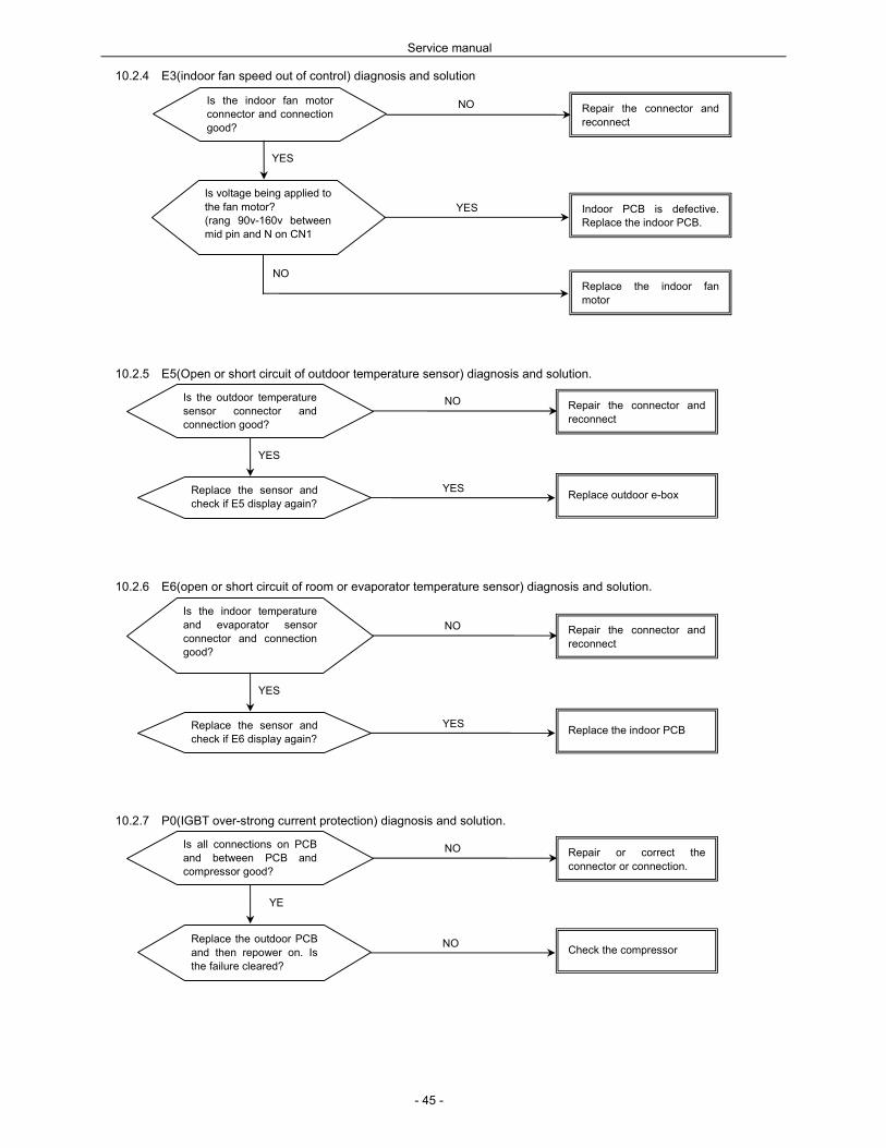
10.2.4 E3(indoor fan speed out of control) diagnosis and solution
10.2.5 E5(Open or short circuit of outdoor temperature sensor) diagnosis and solution.
10.2.6 E6(open or short circuit of room or evaporator temperature sensor) diagnosis and solution.
10.2.7 P0(IGBT over-strong current protection) diagnosis and solution.
Is all connections on PCB and between PCB and compressor good?
Repair or correct the connector or connection.
Replace the outdoor PCB and then repower on. Is the failure cleared?
NO
YE
Check the compressor NO
Is the indoor temperature and evaporator sensor connector and connection good?
Repair the connector and reconnect
Replace the sensor and check if E6 display again?
NO
YES
Replace the indoor PCB YES
Is the outdoor temperature sensor connector and connection good?
Repair the connector and reconnect
Replace the sensor and check if E5 display again?
NO
YES
Replace outdoor e-box YES
Is the indoor fan motor connector and connection good?
Repair the connector and reconnect
Is voltage being applied to the fan motor? (rang 90v-160v between mid pin and N on CN1
NO
YES
Indoor PCB is defective. Replace the indoor PCB.
YES
Replace the indoor fan motor
NO

Service manual
- 46 -
10.2.8 P1(over voltage or too low voltage protection) diagnosis and solution.
10.2.9 P2(temperature protection of compressor top) diagnosis and solution.
10.2.10 P4(inverter compressor drive error) diagnosis and solution.
Is the connection of compressor good? Is the wiring sequence right? The voltage range proper?
Replace the outdoor E-box.
If the problem comes to again, check coil resistance of inverter compressor, is it 0.668ohm?
YES
Replace inverter compressor
Reconnect and retry NO
NO
Is the power supply good? Be sure the power supply is normal when using the units
NO
YES
Replace the outdoor e-box.
YES
Does compressor operate?
Is the connection good?
Is refrigerant circulation volume normal?
NO
NO
Charge refrigerant
Is abnormality the same after gas charging?
NO Check refrigerant system (such as clogging of capillary, etc)
Reconnect and retest. NO
YES
Is protector normal? Replace the protector.
NO
YES
Check the outdoor main PCB. Is there some problem?
Replace the outdoor PCB.
YES

Service manual
- 47 -
10.3. Temperature Sensors. Room temp.(T1) sensor,
Indoor coil temp.(T2) sensor,
Outdoor coil temp.(T3) sensor,
Outdoor ambient temp.(T4) sensor,
Compressor exhaust temp.(Te) sensor.
Measure the resistance value of each winding by using the multi-meter.
Some frequently-used R-T data for T1, T2, T3 and T4 sensor:
Temperature () 5 1
0
1
5
2
0
2
5
3
0
4
0
5
0
6
0
Resistance Value (KΩ) 2
6.9
2
0.7
1
6.1
1
2.6
1
0 8
5.
2
3.
5
2.
4
Some frequently-used R-T data for Te sensor:
Temperature () 5 1
5 25 35 60 70 80
9
0
1
00
Resistance Value (KΩ) 14
1.6
8
8
5
6.1
3
6.6
1
3.8
9.
7
6.
9 5
3.
7
KΩ