Service Manual - Indesit Companyservicenet.indesitcompany.com/data/img_sm/sm59397.pdf · Before...
21
Service Manual Washing Machine Http://global.midea.com.cn Note: Before serving the unit,please read this at first, Always contact wih your service center if meet problem.
Transcript of Service Manual - Indesit Companyservicenet.indesitcompany.com/data/img_sm/sm59397.pdf · Before...
Service ManualWashing Machine
Http://global.midea.com.cn
Note:
Before serving the unit,please read this at first,Always contact wih your service center if meet problem.

TABLE OF CONTENTS
1. SAFETY PRECAUTION.........................................................................................................
1.1 Safety Precaution.................................................................................................................
2.2 Waring..................................................................................................................................
2.TROUBLESHOOTING...........................................................................................................
2.2 Fault tree............................................................................................................................
3. UNPACKING WAYS OF MAIN PARTS.............................................................................
2.1 Malfuction and solution....................................................................................................
2.3 Not turn or one-way turn when wash................................................................................
2.4 Abnormal downtime midway............................................................................................
2.5 Abnormal noise and big vibration.....................................................................................
2.6 No bilging and bilging intermittent...................................................................................
2.7 Water does not stop........................................................................................................
2.8 No drainage......................................................................................................................
2.9 No spinning......................................................................................................................
2.10 Leaking.............................................................................................................................
2.11 Oily shape dirt adherent...................................................................................................
2.12 Anomaly alarm.................................................................................................................
3.1 Product disassembly precautions and steps.....................................................................
4. CIRCUIT DIAGRAM............................................................................................................
1
5.EXPLORED VIEW & LIST OF PARTS..............................................................................
2
2
2
3
3
4
5
6
7
8
9
10
11
12
13
14
15
15
4.1 The wiring picture..............................................................................................................
4.2 The electrical principle picture..........................................................................................
21
21
21
22

1.1 Safety Precaution� To prevent injury to the user or other people and property damage, the following instructions must be followed.
� Incorrect operation due to ignoring instruction will cause harm or damage.
� Before service unit, be sure to read this service manual at first.
1.2 Warning
¾ Installation
� Do not use a defective or underrated circuit breaker . Use
this appliance on a dedicated circuit.
There is risk of fire or electric shock.
� For electrical work, contact the dealer , seller , a qualified
electrician, or an Authorized service center .
Do not disassemble or repair the product, there is risk of fire
or electric shock.
� Always ground the product.
There is risk of fire or electric shock.
� Install the panel and the cover of control box securely.
There is risk of fire of electric shock.
� Always install a dedicated circuit and breaker .
Improper wiring or installation may cause fore or electric
shock.
� Use the correctly rated breaker of fuse.
There is risk of fire or electric shock.
� Do not modify or extend the power cable.
There is risk of fire or electric shock.
� Do not install, remove, or reinstall the unit by yourself
(customer).
There is risk of fire, electric shock, explosion, or injury.
� Be caution when unpacking and installing the product.
Sharp edges could cause injury, be especially careful of the
case edges and the fins on the condenser and evaporator.
� For installation, always contact the dealer or an
Authorized service center.
There is risk of fire, electric shock, explosion, or injury.
� Do not install the product on a defective installation stand.
It may cause injury, accident, or damage to the product.
� Be sure the installation area does not deteriorate with age.
If the base collapses, the wash machine could fall with it,
causing property damage, product failure, and personal
injury.
� Take care to ensure that power cable could not be pulled
out or damaged during operation.
There is risk of fire or electric shock.
� Do not place anything on the power cable.
There is risk of fire or electric shock.
� Do not plug or unplug the power supply plug during
operation.
There is risk of fire or electric shock.
� Do not touch (operation) the product with wet hands.
There is risk of fire or electric shock.
� Do not place a heater or other appliance near the power
cable.
There is risk of fire and electric shock.
� Do not allow water to run into electric parts.
It may cause fire, failure of the product, or electric shock.
� Do not store or use flammable gas or combustible near the
product.
There is risk of fire or failure of product.
� Do not use the product in a tightly closed space for a long
time.
Oxygen deficiency could occur.
� If strange sounds, or small or smoke comes from product.
Turn the breaker off or disconnect the power supply
cable.
There is risk of electric shock or fire.
� Stop operation and close the window in storm or
hurricane. If possible, remove the product from the
window before the hurricane arrives.
There is risk of property damage, failure of product, or
electric shock.
� Be caution that water could not enter the product.
There is risk of fire, electric shock, or product damage.
� Turn the main power off when cleaning or maintaining
the product.
There is risk of electric shock.
� When the product is not be used for a long time,
disconnect the power supply plug or turn off the breaker .
There is risk of product damage or failure, or unintended
operation.
¾
1. SAFETY PRECAUTION
2
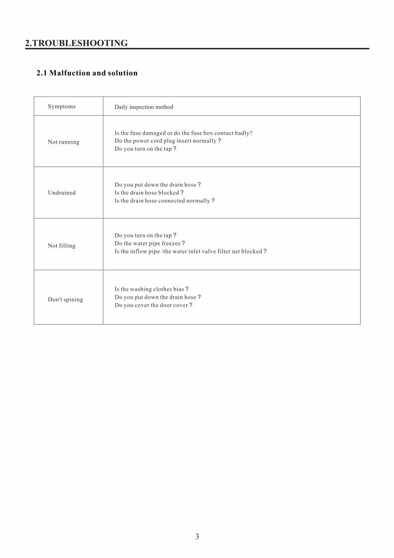
Daily inspection method
2.TROUBLESHOOTING
2.1 Malfuction and solution
Symptoms
Not running
Undrained
Not filling
Don't spining
Is the fuse damaged or do the fuse box contact badly?
Do the power cord plug insert normally?
Do you turn on the tap?
Do you put down the drain hose?
Is the drain hose blocked?
Is the drain hose connected normally?
Do you turn on the tap?
Do the water pipe freezes?
Is the inflow pipe /the water inlet valve filter net blocked?
Is the washing clothes bias?
Do you put down the drain hose?
Do you cover the door cover?
3

Press the power switch and connect the water inlet valve, Whether the water inlet valve moves or not
Change water inlet
Not lighting
fusi
Not having ac
Having ac voltage lighti
controller board
2.TROUBLESHOOTING
2.2Fault tree
1.All operation failure
After the power switch
connects,the luminescence tubes are lightor not
water inlet valve
Change
Check Washing
Whether controller board into lines have ac voltage or not
After the power switch connects,whether the power cord terminalsconnect
Check water inlet valve, motor, capacitors, etc
water inlet valve, motor, capacitor, etc. Electronics components damage
Change the damaged parts
have ac controller board change
change
controller board changeconnec
Not
not have ac
Not Power switch damaging Harness disconnection badly
Change power switch Change Harnessreinstall Harness
4

2.3 Not turn or one-way turn when wash
YES
YES
YES
YES
NO
Whether Bearing department locks the Clutch body is normal or not
(now please check whether the motor or capacitance is normal or not?)
NO
NO
2.TROUBLESHOOTING
Start anhydrous program, no water washing and confirm the motor is no action
Inspect the drive system carefully
YES
YES
NO
Measure the voltage across the motor
The Motor heating protects work or not?
Please confirm the reason
The motor capacity is short/open circuit or not?
Change Motor Capacitor
Change Motor
Measure the voltage across the controller board
Change Motor Capacitor
Change Controller Board
5

2.4 Abnormal downtime Midway
2.TROUBLESHOOTING
There is water in the washing beck.
Retractor damage
Drain Hose was not put down
Drain Hose is blocked
Drain Hose is too long, too high
Drain Pump damage
Drain Valve is blocked
Change a Retractor
Put down the Drain Hose
Dredge Drain Hose
Adjust Drain Hose
Change Drain Pump
Dredge Drain Valve
The spinning stops unexpectedly
The door switch
The machine place not level
Washings in together
Cover Switch damage
Suspend Pole damage
Balance ring damage
Flat the washing machine
Reposition washing
Change Cover Switch
Change Suspend pole
Change Balance ring
6
NO
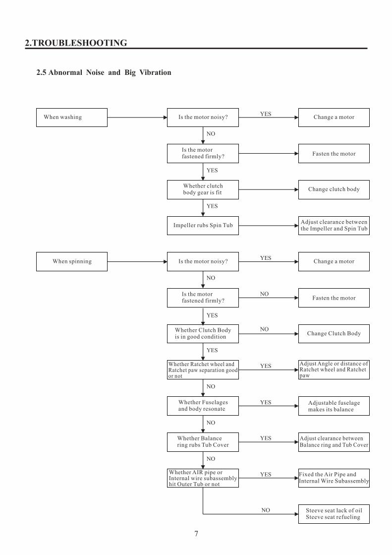
2.5 Abnormal Noise and Big Vibration
NO
YES
2.TROUBLESHOOTING
When washing Is the motor noisy? Change a motor
YES
YES
Is the motor fastened firmly? Fasten the motor
Whether clutch body gear is fit
Change clutch body
Impeller rubs Spin TubAdjust clearance between the Impeller and Spin Tub
When spinning Is the motor noisy?YES
Change a motor
Is the motor fastened firmly?
NO
NOFasten the motor
Whether Clutch Body is in good condition
Change Clutch Body
Whether Fuselages and body resonate
Adjustable fuselage makes its balance
Whether Balance ring rubs Tub Cover
Adjust clearance between Balance ring and Tub Cover
Fixed the Air Pipe and Internal Wire Subassembly
NO
YES
YES
YES
YES
NO
NO
NO
YES
YES
Whether Ratchet wheel and Ratchet paw separation good or not
Adjust Angle or distance of Ratchet wheel and Ratchet paw
Whether AIR pipe or Internal wire subassembly hit Outer Tub or not
Steeve seat lack of oilSteeve seat refueling
7
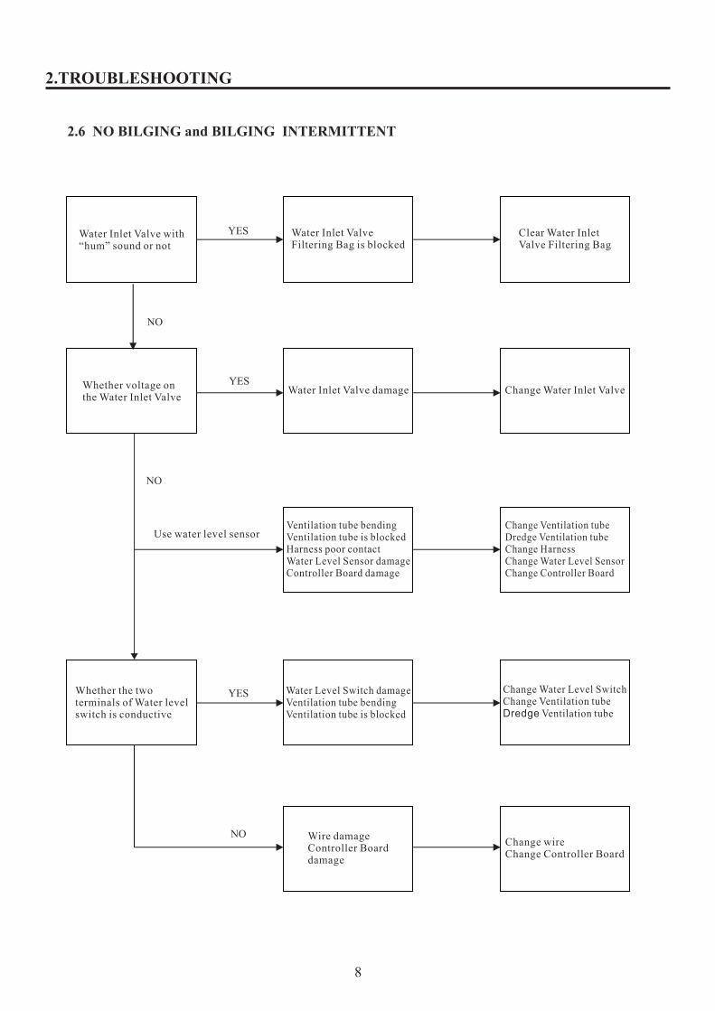
2.6 NO BILGING and BILGING INTERMITTENT
YES
NO
NO
YES
YES
NO
2.TROUBLESHOOTING
Water Inlet Valve with“hum” sound or not
Water Inlet Valve Filtering Bag is blocked
Clear Water Inlet Valve Filtering Bag
Whether voltage on the Water Inlet Valve
Water Inlet Valve damage Change Water Inlet Valve
Use water level sensor Ventilation tube bendingVentilation tube is blockedHarness poor contactWater Level Sensor damageController Board damage
Change Ventilation tubeDredge Ventilation tubeChange HarnessChange Water Level SensorChange Controller Board
Whether the two terminals of Water level switch is conductive
Water Level Switch damageVentilation tube bendingVentilation tube is blocked
Change Water Level SwitchChange Ventilation tubeDredge Ventilation tube
Wire damageController Board damage
Change wireChange Controller Board
8
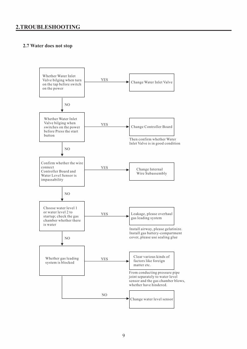
2.7 Water does not stop
YES
NO
NO
2.TROUBLESHOOTING
YES
YES
YES
YES
NO
NO
NO
Whether Water Inlet Valve bilging when turn on the tap before switch on the power
Change Water Inlet Valve
Whether Water Inlet Valve bilging when switches on the power before Press the start button
Change Controller Board
Then confirm whether Water Inlet Valve is in good condition
Confirm whether the wire connectController Board and Water Level Sensor is impassability
Change Internal Wire Subassembly
Choose water level 1 or water level 2 to startup; check the gas chamber whether there is water
Leakage, please overhaul gas leading system
Install airway, please gelatinize. Install gas battery-compartment cover, please use sealing glue
Whether gas leading system is blocked
Clear various kinds of factors like foreign matter etc.
From conducting pressure pipe joint separately to water level sensor and the gas chamber blows, whether have hindered.
Change water level sensor
9

2.8 NO DRAINAGE
2.TROUBLESHOOTING
YES
NO
Whether there is a tractor moves
Drainage road is blocked Drain Hose deformationDrain Valve is blockedDrain Hose is blockedDrain Hose was not put downDrain Pump is blocked
Dredge Drainage roadChange Drain HoseDredge Drain ValveDredge Drain Hoseput downDrain HoseDredge Drain Pump
Tractor damage Cover Switch damageHarness poor contactController Board damage
Change TractorChange Cover SwitchChange HarnessChange ControllerBoard
10

2.9 NO SPINNING
NO
NO
YES
YES
2.TROUBLESHOOTING
Whether Drainage is normal
Drainage road is blocked
Drain Hose deformation
Drain Valve is blocked
Drain Hose is blocked
Drain Hose were not put down
Drain Pump is blocked
Dredge Drainage road
Change Drain Hose
Dredge Drain Valve
Dredge Drain Hose
Put down Drain Hose
Dredge Drain Pump
Whether voltage on the motor
The motor damage
Motor Capacitor damage
Belt Loose/fault
Clutch Body damage
Change motor
Change Motor Capacitor
Adjust/Change belt
Change Clutch Body
Controller Board damage
Cover Switch damage
Water Level Sensor damage
Water Level Switch damage
Harness poor contact
Change Controller Board
Change Cover Switch
Change Water Level Sensor
Change Water Level Switch
Change Harness
11

2.10 Leaking
2.TROUBLESHOOTING
Drain Hose Leaking
Drain Valve Corrugated pipe was out of shape. Retractor damage.Drain Hose is not been hung up .Drain Pump is clogged
is clogged. Dredge the Drain ValveChange corrugated pipeChange Retractor Reinstall the Drain Hose Dredge the Drain Pump
Water on the groundWhen washing
The quantity of washing water is not set up correctly.Belt over tighten
Choose appropriate washing water.The tension adjust.
When rinsing
Fill excess water pressure. Washing float on water.
Adjust the tap.Press the washing into water.
When spinning
Drain Hose damaged.Drain Hose install improperly.
Change Drain Hose.Reinstall Drain Hose.
Others
Water Inlet Hose improper installation.Water Inlet Hose damaged.Universal tie-in damage.Ventilated hose damage or fall off.Outer Tub damage. Water is leaking.Low temperature form dew.
▲Reinstall Water Inlet Hose
▲Change Water Inlet Hose
▲change Universal tie-in
▲Repair or change Ventilated hose
▲Change Outer Tub
▲Change Clutch Body
▲Wipe the dew
12

2.11 Oily shape dirt adherent
2.TROUBLESHOOTING
Common in use laundry powder
Spin Tub insideImpeller inside
Black dirt is Spin Tub inside
Or Impeller inside
latched onto
Clean Spin Tub inside or Impeller inside
13

2.12 Anomaly alarm
EEPROM
NO
OK
OK
NO
2.TROUBLESHOOTING
the Power Switch failed
Turn off the power and restart after 5 seconds
Replace a Power Switch or Controller Board
Replace a Controller Board
Water inlet is not normal
Turn on the tapPressure is too low, Try to increase water
Not drainingPut down the Drain hose ,Try to clear the obstruction
Cover is not closed Close the washing machine Cover
Washings in together
Lays aside the washings in tub evens
Water Level Sensor alarm sounds
Check whether inserted lines of Water level sensor have insertedCheck whether Air Pipe without leakage
Replace a Water Level Sensor
Unable to fuzzy weighing
Replace a Controller Board
14

3. 1 Product disassembly precautions and steps:
3.UNPACKING WAYS OF MAIN PARTS
1> General attention:1.When you remove or repair, please you must unplug the power cord firstly2.When you connect wire,you are sure to connect wire with wiring cap ,use the tool to press wiring cap for connecting firmly and use tape to make the line insulation fully.3.When you plug wire and connect wires, you must insert terminals to the roots for not easily pulling.4.When you decorate internal wires,you fix internal wires to avoid encountering moving parts for example v-belt, pulley,suspend pole, etc or high temperature parts according to original state. 5.The removing screws must be preserved goodly,because you need screws to install. 6.When you diagnose faults, you are very careful to not get an electric shock if you need to operate in electricity situation.
2> Product disassembly steps:1. Remove the screws on the rear cover, remove the drain hose screws and then take down the rear cover.2. Remove the earth screws, capacitor screws, and then pull out the air pipe.3. Pull the insulating bag and then remove the wire connector.4. Pull out the front control panel screws, and then remove the top cover screws.5. Take down the top cover subassembly, and put it in the right place6. Remove the controller board screws, pull out the controller board terminals,and then take down the controller board and the front control panel.7. Take down the back control panel, cover switch, nozzle ,water level sensor,and internal wire subassembly .8. Take down cover pin, twist spring and take out cover subassembly..9. Remove the outer tub cover screws and the impeller screws, finally take out the outer tub cover and the impeller.10.Take out impeller adjusting washer, remove the big nut and take out the coupling flange washer.11. Take out spin tub subassembly.12. Take out the outer tub subassembly. 13. Turn the outer tub subordinate-subassembly, and remove the motor screws, the bracket screws, the clutch body subassembly screws, the retractor screws,and the drain pump screws(or drain valve subassembly screws), finally take out motor,bracket, clutch body subassembly, retractor,and drain pump(or drain valve subassembly) .14. Remove the base plate screws, and then take out outer tub subordinate-subassembly on the base plate15. In turn counterclockwise (or clockwise) order take out the suspend poles, and then put them down on the ground.16. Remove the power cord.17. Remove the base subassembly for cabinet screws,and then take out the base subassembly for cabinet.
15

3> Product disassembly step-by-step instructions:
3.UNPACKING WAYS OF MAIN PARTS
Product steps serial number Product dissembling detailed steps Picture caption
1. Remove the screws on the rear cover, remove the drain hose screws and then take down the rear cover (make the drain hose and cabinet separate)
①Remove the screws on the rear cover (Red circle part) and then take out the rear cover.
②Remove the drain hose screws to make the drain hose and cabinet separate
2. Remove the earth screws, capacitor screws, and then pull out the air pipe. (make the air pipe and suspend poles separate)
①Remove the earth screws to make the earth wire subassembly and cabinet separate
②Remove the capacitor screws, take down capacitor catch
③Pull out the air pipe to make the air pipe and suspend poles separate (When you install the air pipe, you remember to coat adhesive for preventing leakage)
3. Pull the insulating bag and then remove the wire connector.
①Pull the insulating bag
②Remove the wire connector.
16

3.UNPACKING WAYS OF MAIN PARTS
4. Pull out the front control panel screws, and then remove the top cover screws.
①Pull out the front control panel screws (sometimes need to remove the hole cover)
②Remove the top cover front and back screws.
5. Take down the top cover subassembly, and put it in the right place (avoid to scratch the top cover subassembly)
6. Remove the controller board screws, pull out the controller board terminals, and then take down the controller board and the front control panel.
①Remove the controller board screws, pull out the controller board terminals(When you plug wire and connect wires, you must insert terminals to the roots for not easily pulling.)
②Take down the controller board and the front control panel separately
7. Take down the back control panel, cover switch, nozzle , water level sensor, and internal wire subassembly .
①Remove the back control panel screws, and take out the back control panel.②Remove the cover switch l screws, and take out cover switch. ③Take down the nozzle. ④Remove the water level sensor screws, and take out the water level sensor.⑤Take out the internal wire subassembly .
8. Take down cover pin, twist spring and take out cover subassembly
①Take down cover pin
②Take down twist spring and take out cover subassembly.
17
3.UNPACKING WAYS OF MAIN PARTS
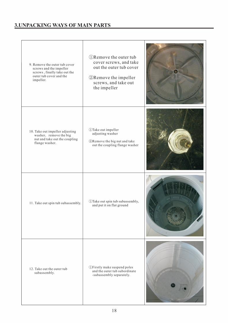
9. Remove the outer tub cover screws and the impeller screws , finally take out the outer tub cover and the impeller.
①Remove the outer tub cover screws, and take out the outer tub cover ②Remove the impeller screws, and take out the impeller
10. Take out impeller adjusting washer, remove the big nut and take out the coupling flange washer.
①Take out impeller adjusting washer
②Remove the big nut and take out the coupling flange washer
11. Take out spin tub subassembly. ①Take out spin tub subassembly, and put it on flat ground
12. Take out the outer tub subassembly.
①Firstly make suspend poles and the outer tub subordinate -subassembly separately.
18
3.UNPACKING WAYS OF MAIN PARTS
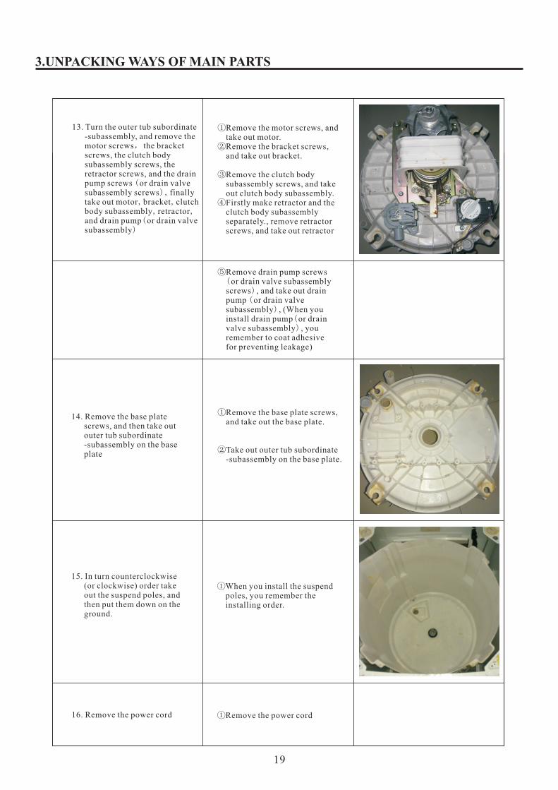
13. Turn the outer tub subordinate -subassembly, and remove the motor screws, the bracket screws, the clutch body subassembly screws, the retractor screws, and the drain pump screws (or drain valve subassembly screws), finally take out motor,bracket,clutch body subassembly, retractor, and drain pump(or drain valve subassembly)
①Remove the motor screws, and take out motor. ②Remove the bracket screws, and take out bracket.
③Remove the clutch body subassembly screws, and take out clutch body subassembly. ④Firstly make retractor and the clutch body subassembly separately., remove retractor screws, and take out retractor
⑤Remove drain pump screws (or drain valve subassembly screws) , and take out drain pump (or drain valve subassembly) , (When you install drain pump(or drain valve subassembly) , you remember to coat adhesive for preventing leakage)
14. Remove the base plate screws, and then take out outer tub subordinate -subassembly on the base plate
①Remove the base plate screws, and take out the base plate.
②Take out outer tub subordinate -subassembly on the base plate.
15. In turn counterclockwise (or clockwise) order take out the suspend poles, and then put them down on the ground.
①When you install the suspend poles, you remember the installing order.
16. Remove the power cord ①Remove the power cord
19

3.UNPACKING WAYS OF MAIN PARTS
17. Remove the base subassembly for cabinet screws,and then take out the base subassembly for cabinet.
①Remove the base subassembly for cabinet screws,and then take out the base subassembly for cabinet.
②Take out the cabinet.
20