SERVICE MANUAL Washing machine 2006 MOON - Indesit...
31
All the parts included in this document are the property of Indesit Company S.p.A. All rights reserved. This document and all the information contained in it are supplied without responsibility for possible errors or omissions and no part of it can be reproduced, used or removed without written permission or a contractual clause. SERVICE MANUAL Washing machine 2006 MOON SERVICE MANUAL Washing machine 2006 MOON Service Manual MOON - 2006 Linguage English Edition 2006.06.12 GB
Transcript of SERVICE MANUAL Washing machine 2006 MOON - Indesit...

All the parts included in this document are the property of Indesit Company S.p.A.
All rights reserved. This document and all the information contained in it are supplied without responsibility for possible errors or omissions and no part of it can be reproduced, used or removed without written permission or a contractual clause.
SERVICE MANUAL
Washing machine 2006 MOON
SERVICE MANUAL
Washing machine 2006 MOON
Service ManualMOON - 2006
LinguageEnglish
Edition2006.06.12
GB

2
LinguageEnglish
GB
Service ManualMOON - 2006
Edition2006.06.12
CONTENTS OF THE MANUAL: NOTE FOR THE ENGINEER.This manual is a supporting document for technical personnel. It contains a description of the various product types, the general operating principles and indications concerning assistance.
Technical personnel should, in any case, consult the specifi c model on . (servicenet.
indesitcompany.com) to access data and updates of wiring diagrams, technical bulletins and spare parts.

3
LinguageEnglish
GB
Service ManualMOON - 2006
Edition2006.06.12
CONTENTS
1. PRODUCT TYPE 4-6 Key 4
Interfaces 5
Technical data 5
Energy Label 6
2. OPERATING LOGIC 7-13 Innovative product characteristics 7-9
Instructions for settings and operation 10-11
Programmes 12-13
3. COMPONENTS 14
4. WIRING DIAGRAMS 15
5. ASSISTANCE 16-25 Demo Mode 16
Autotest (Testing / Running-in) 16
Autotest Sequence 16
Faults and Solutions 17-19
Doctor 20
Troubleshooting 20
Dismantling/Assembly 21-26
6. EXPLODED VIEWS 27-30

TY
PE
GB
4
Service ManualMOON - 2006
LinguageEnglish
Edition2006.06.12
1. PRODUCT TYPE:
1.1. KEY:
S I X L 12 5 S 1st letter 2nd letter 3rd letter 4th letter 1st&2nd Number 3rd Number 5th letterProduct line Brand Type Type Max Spin Speed Specs ColourS = Smart I = Indesit X = maxi 6 kg. L = led 8 = 800 0 S = silver unit S = Slim D = display 10 = 1000 1 blank = white unit . .
. .
. .
14 = 1400 7

TY
PE
GB
5
Service ManualMOON - 2006
LinguageEnglish
Edition2006.06.12
1.2. INTERFACE:
8
9
1. On/OFF/RESET BUTTON2. DOOR LOCK LED 3. Cotton Whites/PAUSE BUTTON4. Mixed Coloureds Easy Iron/PAUSE BUTTON5. Delicates/PAUSE BUTTON
1.3. TECHNICAL DATA:
MODEL: MOONCapacity: da 1 a 6,0 Kg
Dimensions:
Width: 59,5 cm
Height: 85 cm
Depth: 56,5 cm
Water connections:
Maximum pressure: 10 bar
Minimum pressure: 0,5 bar
Tank Capacity 52 litres
Electrical connection:
Voltage: 220/240 volt. 50 Hz
Maximum power consumption: 1850 Watt.
Maximum spin speed: 1200 giri.
6. Rapid 30’/Rinse Only/PAUSE BUTTON7. Programme PROGRESS RING 8. Door 9. Filter Cover
4
1
5
6
2
3
7

TY
PE
GB
6
Service ManualMOON - 2006
LinguageEnglish
Edition2006.06.12
1.3. ENERGY LABEL:
EnergyManufacturerModel
Washingmachine
More efficient
Less efficient
Energy consumptionkWh/cycle
(based on standard test resul tsfor 60° C cotton cycle)
Actual energy consumption willdepend on how the appliance is used
Washing performanceA: higher G: lower
Spin drying performanceA: higher G: lower
Spin speed (rpm)
Capacity (cotton) kg
Water consumption
Noise Washing
(dB (A) re 1 pW) Spinning
Further information is contained in productbrochures
Norm EN 60456Washing machine label Directive 95/12/EC
MOON
1200
6. 0
52
B C D E F GA
1.02
A
INDESIT
B C D E F GA
+
Brand
Model
Power Class
Power Consumption in standard cycle (kW/h)
Washing Class
Spin Class
RPM
Maximum load (kg).
Maximum water consumption in standard cycle

OP
ER
AT
ION
7
GB
Service ManualMOON - 2006
LinguageEnglish
Edition2006.06.12
2. OPERATING LOGIC:
2.1. PRODUCT CHARACTERISTICS AND TECHNOLOGICAL INNOVATIONS:
PROGRAMME SELECTOR:The new circular programme selector features 5
backlit buttons, a central disc bearing the LOGO
and a ring with 12 blue leds between the buttons
and the disc. The leds around the ring light up to
indicate programme progress and, in the event of a
malfunction, the specifi c fault.
The MOON washing machine features many technological innovations, which are listed below:
WATER SYSTEM:This machine features a water system designed
around two solenoid valves and a water dispenser,
connected by two hoses, which manage water
and detergent loading. With all programmes, the
appliance starts loading water with the fi rst solenoid
valve, but activates the Oko system only with the
“Cotton 60°” programme. During the wash phase,
water is loaded as follows:
1. The washing machine loads water with the fi rst
solenoid valve. (Flow 1)
2. Water is drained for two seconds (only for the
standard programme – Cotton 60°)3. The machine fi nishes loading water with the second
solenoid valve, drawing the detergent into the drum.
(Flow 2)During the rinse phase, the machine draws in fabric
softener with both solenoid valves. The fl ow of water
creates a cross-stream inside the dispenser (Flow 1
+ 2), generating a thrust that allows the water to exit
through all the holes, drawing fabric softener into the
drum and cleaning all the other detergent dispenser
compartments.
1. Programme selector
2. Water system
3. Detergent dispenser
4. Door seal / Door
5. Vent tube
6. Drain pump
7. Conductivity sensor
Detailed explanation of these components is
provided below.
12
1
2 2 1+2
OP
ER
AT
ION
8
GB
Service ManualMOON - 2006
LinguageEnglish
Edition2006.06.12
DETERGENT DISPENSER:The detergent dispenser is located inside the
appliance, on the inside of the door.
It can be removed for cleaning by lifting it upwards
and carefully releasing the top cover.
The dispenser consists of three compartments: the
fi rst (left to right) is for liquid detergents.
The second (middle compartment) is for powder
detergents, while the last (right-hand) is for fabric
softener.
VENT TUBE:The vent tube is connected to the part of the tub
where the water inlet feed is normally connected.
The vent tube steam outlet is located next to the inlet
hose at the point where, in machines with hot water
solenoid valves, the solenoid valve hose connection
is usually situated.
DOOR SEAL / DOOR:The water dispenser is located at the top of the door
seal, fi xed with a metal plate.
The door does not allow you to see inside the drum;
the detergent dispenser is inside, and a small drip
tray provided with sponge has been fi tted under it.

OP
ER
AT
ION
9
GB
Service ManualMOON - 2006
LinguageEnglish
Edition2006.06.12
DRAIN PUMP:The drain pump is equipped with a new self-cleaning
bayonet fi lter which prevents large objects such as
coins, buttons, etc. from ending up inside the pump,
thus avoiding blockages and noisy operation.
It is located at the bottom right-hand side of the
machine. To access the fi lter, simply turn the fi lter
cover anti-clockwise until the bayonet coupling
releases, allowing access to the fi lter.
CONDUCTIVITY SENSOR: The Moon washing machine is equipped with a new
Conductivity Sensor located on the plastic tub next
to the Oko hose, as shown in the photograph.
The Conductivity Sensor manages the “30 min” or
“Daily” programme. Its functions are:
1. If the wash load consists of clothes to be washed
without detergent, the machine will load water
and then test the level of alkalinity in the wash
water; if no alkalinity is present, the machine will activate the standard “30 min” wash cycle;
2. If, on the contrary, the sensor detects that the
machine has been loaded with laundry plus
detergent, it will activate two 15 minute rinse
cycles.
NB: The conductivity sensor is provided with
a gasket to guarantee seal and prevent water
leaks.
A plastic cover has been fi tted on the fi lter to prevent
hands from coming into contact with the electrical
part of the pump, which must not be eliminated.

OP
ER
AT
ION
10
GB
Service Manual
MOON - 2006
Linguage
English
Edition
2006.06.12
2.2. APPLIANCE OPERATION:
SWITCHING THE APPLIANCE ON/OFF:
The machine is switched on by pressing the On
button. The symbol on the button lights up, after
which the programme buttons start fl ashing and
the leds on the ring light up one after another. At
this point the machine is on Stand By and is ready
for use.
S E L E C T I N G / S TA R T I N G A
PROGRAMME:
Programmes are started by pressing the relative
programme button, upon which the washing machine
starts immediately.
The Power On button and the selected programme
button leds will remain lit, while the other programme
leds and all those around the ring will switch off. The
leds around the ring will light up one after another to
indicate programme progress.
PAUSE/RIAVVIO DEL PROGRAMMA IN CORSO:
PAUSE/RESTART PROGRAMME:The Pause/Restart function is used for interrupting
a wash cycle, which can then be restarted from the exact point in the cycle where it was interrupted.
When the button of the programme in progress is
pressed, the washing machine stops, the Power On
button remains lit, the leds around the ring light up and start fl ashing, as does the selected programme led.
To restart the wash programme, simply press the
programme button once more.
OP
ER
AT
ION
11
GB
Service Manual
MOON - 2006
Linguage
English
Edition
2006.06.12
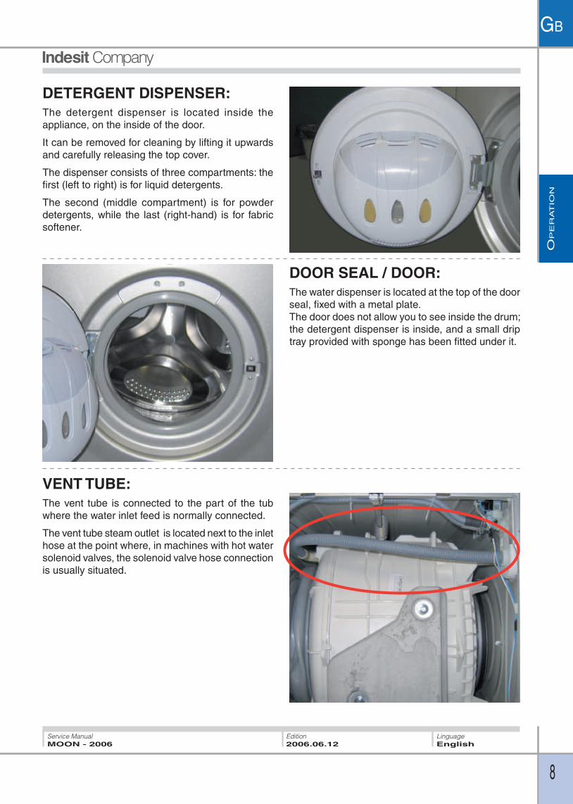
RESETTING A PROGRAMME IN PROGRESS:
To reset a programme in progress, press and hold
the On button for more than 1 second.
The washing machine will switch off and the
programme in progress will be cancelled.
Before switching off, the washing machine
automatically runs a drain cycle, whether there is
water in the drum or not.
During draining, the Power On button flashes.
lampeggerà.
PROGRAMME PROGRESS:The progress of the wash programme is indicated
by the leds around the ring.
These start to light up in a clockwise direction,
starting from the led at 12 o’clock.
As more leds light up, the previous ones remain lit.
AT THE END OF THE SELECTED
PROGRAMME:When the wash programme ends, the Power On
led and the selected programme led remain lit,
while the leds around the ring fl ash. L’avanzamento
del programma di lavaggio è indicato dai led della
corona.
OP
ER
AT
ION
12
GB
Service Manual
MOON - 2006
Linguage
English
Edition
2006.06.12
2.3. PROGRAMMES:
The wash cycle selection buttons correspond to the following wash programmes:
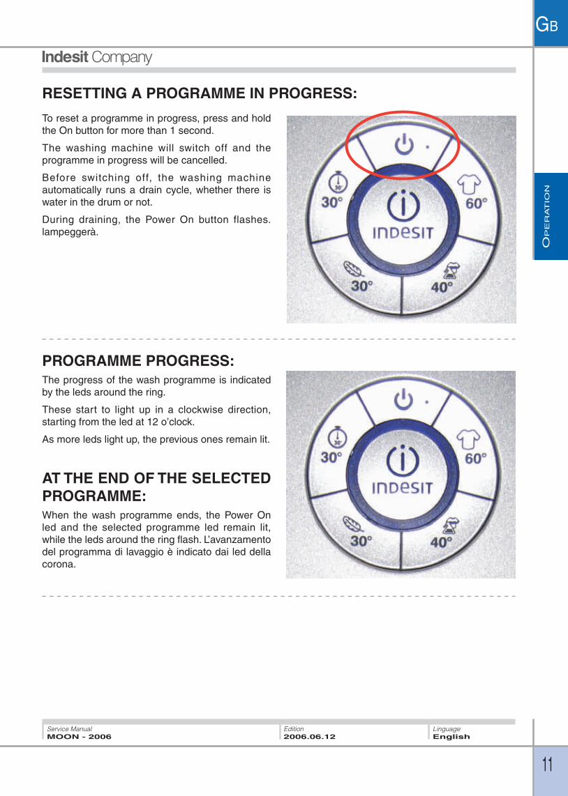
• Cotton Whites:
Standard 60° cotton wash cycle. (Spin 1200 rpm)
• Mixed coloureds/Easy Iron:
Wash cycle suitable for garments of mixed colours in cotton or synthetic fabric, with a
wash temperature of 40°.
The spin cycle must be suitably reduced to guarantee the Easy Iron function. (The spin
speed for this programme is 1000 rpm, except for the last 20 seconds at 1200 rpm).
• Gentle cycle with fi nal spin:
To wash: delicate synthetics, cotton and wool press the “Delicates” button. After 3
seconds “Delicates” and “Rapid 30 min” will fl ash at the same time. Press “Delicates”
again to carry out washing that will fi nish with a gentle spin (Spin speed 600 rpm).
• Gentle cycle without fi nal spin:
To wash: silk, curtains (do not use for wool) press the “Delicates” button. After 3
seconds “Delicates” and “Rapid 30 min” will fl ash at the same time. Press “Rapid 30
min” to carry out washing without fi nal spin.
NB: At the end of this cycle, the machine will do a spin cycle and automatically empties
the water contained in the drum. It is advisable to immediately remove garments from
the washing-machine at the end of the cycle, in order to avoid excessive creasing.
• Rapid 30’/Rinse Only:
The washing machine uses the Conductivity Sensor to ascertain whether the user has
loaded laundry with detergent.
If clothing with detergent is loaded, the washing machine will activate the “Rinse Only” programme, performing 2 15-minute rinse cycles.
If the Sensor detects no detergent, the washing machine will activate the “Rapid 30
minute” programme. (Spin speed 800 rpm)

OP
ER
AT
ION
13
GB
Service Manual
MOON - 2006
Linguage
English
Edition
2006.06.12
2.3.4 PROGRAMME TABLE
Max load (kg) Temperature
Spin speed (rpm)
Duration Wash cycleFabricsdescription
Hard-wearing white cotton
Coloured cottons and synthetics
Wool, silk and other delicates
Cottons and synthetics
Wash, rinses, intermediate and final spin cycles
Wash, rinses, delicate spin cycle
Wash, rinses, delicate spin cycle (wool) or drain (silk)
WHITES COTTON
MIXED COLOUREDS
DELICATES
RAPID/RINSE ONLY
Wash (only for the “Rapid” programme), rinses, delicate spin cycle
30°/cold water
The programme times given in the table are only approximate and calculated taking into consideration a medium load quantity.

CO
MP
ON
EN
TS
14
GB
Service ManualMOON - 2006
LinguageEnglish
Edition2006.06.12
3. COMPONENTS:
Detergent dispenser.
Display PCB.
Drain Pump Filter.
Washing machine door.
Water Distributor.
Oko System.
Vent tube.
Conductivity Sensor.

WIR
ING D
IAG
RA
MS
15
GB
Service ManualMOON - 2006
LinguageEnglish
Edition2006.06.12
4. WIRING DIAGRAMS:
4
NC
TO BE CONNECTEDTRADITIONAL DOOR LOCK
j15
Vcc
GN
D
SC
L
SD
A
j7
Control
board connector
j12
1211 2
1*
2 1
Lav.
2 1
j13
3
j142
1
21
15
43
21
1
line
neutral
54
32
1
j11
98
RT
N_D
OO
RR
TN
_IP
21
10A
10w
10w
1A
1A
10A
10A
8A
10A
10A
12A
12A
12A
12A
j4j2
j14
j8j3
j1j5
D
65
R R
64
21
3
21
TG
SEN.COND
RX
GND
COMUNE
PIENO
VUOTO
1
97
64
3
23
4
3
2
4
C1
43
21
43
2
1
2 1
2 1
Test
R
TF
RR
5 1
1611
14
1
12
LN
PL
EVP
EVL
OVERFLOWW
1
12
12
12
34
5
Stat.CP
Stat.CI
Sta
t.
1
23
4
5
67
76
53
217
64
32
1
4
5
6a
6a
6a
6a
6a
j9
MT
j13

AS
SIS
TA
NC
E
16
GB
Service ManualMOON - 2006
LinguageEnglish
Edition2006.06.12
5.2. AUTO TEST: The Hardware Key (transparent - C0095669) is used to run the EVOII platform Autotest program.
A BLUE led will light up on the hardware key to indicate that the appliance is an EVOII machine. A
fl ashing RED led on the hardware key (when the key is slotted into the machine) indicates that the
electronic PCB is in communication with the hardware key. If the Hardware Key is unable to establish
a connection with the washing machine, the display shows the letters “ERR” in fl ashing mode.
Initial conditions before starting the Autotest procedure
1. Washing machine with no water in tub.
2. Door closed.
3. Switch on the appliance and plug the hardware key into the slot provided.
To start the Autotest procedure, press and release the button marked AUTOTEST. An audible signal
will be emitted and the message “AUTOTEST” will scroll across the display.
Autotest sequence for Washing Machine
- 1 litre of water for wash cycle solenoid valve.
- 1 litre of water for pre-wash solenoid valve
- 1 litre of water for fabric softener solenoid valve
- Movement at 25 r.p.m.
- Water is heated to 28°
- Drain and spin at 800 r.p.m.
- Stop.
IMPORTANT!!: If the washing machine functions correctly but has previously been stopped due to a FAULT, instead of running the AUTOTEST programme, the FAULT in question will be indicated on the hardware key
display and also on the washing machine display, in various modes depending on the interface type.
5. ASSISTANCE:
5.1. DEMO MODE:
This machine does not feature the Demo Mode function.
AS
SIS
TA
NC
E
17
GB
Service ManualMOON - 2006
LinguageEnglish
Edition2006.06.12
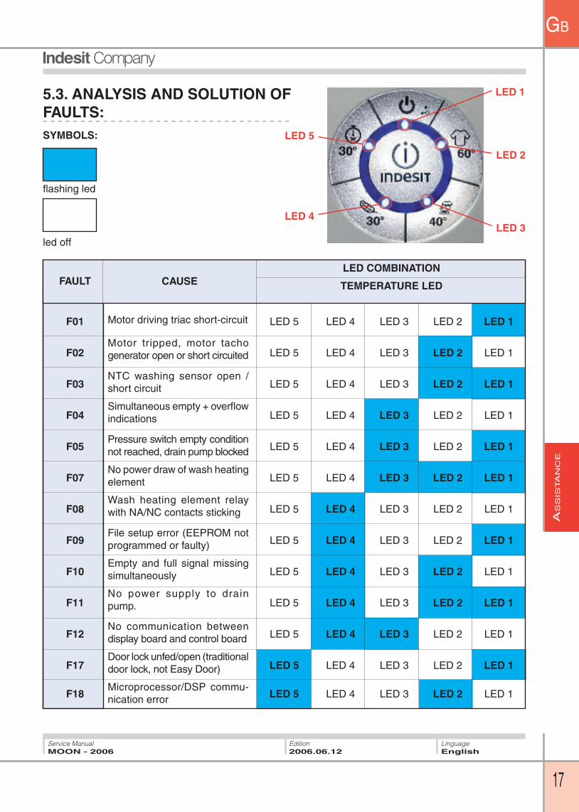
5.3. ANALYSIS AND SOLUTION OF
FAULTS:
LED COMBINATION
FAULT CAUSE TEMPERATURE LED
F01 LED 5 LED 4 LED 3 LED 2 LED 1
F02 LED 5 LED 4 LED 3 LED 2 LED 1
F03 LED 5 LED 4 LED 3 LED 2 LED 1
F04 LED 5 LED 4 LED 3 LED 2 LED 1
F05 LED 5 LED 4 LED 3 LED 2 LED 1
F07 LED 5 LED 4 LED 3 LED 2 LED 1
F08 LED 5 LED 4 LED 3 LED 2 LED 1
F09 LED 5 LED 4 LED 3 LED 2 LED 1
F10 LED 5 LED 4 LED 3 LED 2 LED 1
F11 LED 5 LED 4 LED 3 LED 2 LED 1
F12 LED 5 LED 4 LED 3 LED 2 LED 1
F17 LED 5 LED 4 LED 3 LED 2 LED 1
F18 LED 5 LED 4 LED 3 LED 2 LED 1
SYMBOLS:
fl ashing led
led off
Motor driving triac short-circuit
Motor tripped, motor tacho
generator open or short circuited
NTC washing sensor open /
short circuit
Simultaneous empty + overfl ow
indications
Pressure switch empty condition
not reached, drain pump blocked
No power draw of wash heating
element
Wash heating element relay
with NA/NC contacts sticking
File setup error (EEPROM not
programmed or faulty)
Empty and full signal missing
simultaneously
No power supply to drain pump.
No communication between
display board and control board
Door lock unfed/open (traditional
door lock, not Easy Door)
Microprocessor/DSP commu-nication error
LED 1
LED 2
LED 3
LED 5
LED 4

AS
SIS
TA
NC
E
18
GB
Service ManualMOON - 2006
LinguageEnglish
Edition2006.06.12
FAULT CORRECTIVE ACTIONSCAUSE
- Check for water leaks that may affect connector J9 causing the relative contacts to short;
- Check the motor terminal board (any problems due to aggression caused by manufacturing chemical residues may cause short-circuits);
- Replace card.
- Check motor if blocked;- Check the tacho generator winding and check that there is an
impedance value of between 115 and 170 Ω on the wiring connector J9 between pins 1 and 2. In the case of direct current or alternative current check the wiring between pins 1 and 2 of J9 relative to the tacho generator. With a three-phase motor, make sure there is ohm continuity between J9 pins 6 and 7;
- Replace motor;- Replace card.
- Check effi ciency of contacts on connector J8 on PCB;- Check NTC ensuring that the impedance value at ambient temperature
on wiring connector J8 , pins 11 and 12 , is approximately 20 KΩ;- If the measurement is incorrect, check J8/NTC wiring continuity.
Check the same parameter directly on the NTC.- Replace NTC;- Replace card.
- Check effi ciency of contacts on connector J3 on PCB;- Check condition of pressure switch by checking for impedance on
wiring connector J3 pins 2 and 4 (impedance should be measured only with tub empty) and between pins 2 and 1 (impedance must be present only with water in tub to above the level of half-way up the door);
- Check wiring of connector J3/pressure switch;- Replace pressure switch;- Replace card.
- Check effi ciency of contacts of connector J9 on PCB, checking for the presence of 220V between pins 8 and 9;
- Check that pump is receiving power;- Check pump fi lter + drain outlet to building wall connection;- Renew pump;- Replace card.
- Check effi ciency of contacts on connector J3 on PCB;- Check on connector J3 pins 5 and 6 for continuity of the wash heating
element. The 1800W 230V heating element has a value of 25 Ω;- Check pressure switch connector J3 pins 2 and 3: no impedance
value must be detected (common with full);- Check pressure switch connector J3 pins 2 and 3: an impedance
value must be present;- Replace pressure switch;- Renew heating element;- Replace card.
F01 Motor driving triac short-circuit
Motor tripped, motor tacho generator open or short circuited
NTC washing sensor open / short circuit, or wash heating element relay contacts sticking (signalled at time of full tub)
F03
F02
F04
Simultaneous presence of empty + overfl ow indications. If the pressure switch contact sticks on the empty setting, the machine loads water until reaching the overflow level. The drain pump is
automatically started when the overfl ow contact trips.
Pressure switch empty condition not reached.
F05
Fault indication leds fl ash together with programme button leds.
No power draw of wash heating element (signalled only with pressure switch on empty).
F07

AS
SIS
TA
NC
E
19
GB
Service ManualMOON - 2006
LinguageEnglish
Edition2006.06.12
- Check effi ciency of contacts on connector J3 on PCB;- Check condition of pressure switch by checking for impedance on
J3 wiring connector pins 2 and 4 (impedance should be measured only with tub empty), pins 2 and 3 (impedance should be measured only with water in tub) and pins 2 and 1 (impedance should be measured only with water in tub to above the level of half-way up the door window);
- High level of ambient humidity;
- In the case of PCB made with soldered EEPROM, renew PCB and EEPROM;
- In the case of replacement PCB and EEPROM, check correct insertion of EEPROM in PCB socket.
- Check effi ciency of contacts on connector J3 on PCB;- Check condition of pressure switch by checking for impedance on
J3 wiring connector pins 2 and 4 (impedance should be measured only with tub empty) and pins 2 and 1 (impedance must be present only with water in tub to above the level of half-way up the door window);
- Check wiring of connector J3/pressure switch;- Replace pressure switch;- Replace card.
- Check effi ciency of contacts on connector J9 on PCB;- Check continuity of the pump on connector J15 pins 1 and 2 (for
machines with “Easy Door” door lock) or on connector J9 pins 8 and 9 (for traditional door locks), ensuring that the impedance value is 170 Ω;
- Check wiring of connector J15 (or J9)/pump;- Renew pump;- Replace card.
- Check effi ciency of contacts on connector J11 on PCB;- Check continuity of connector J11/5-way connector of display
PCB;- Renew main PCB;- Renew display PCB.
- Check 230V power supply on wiring connector J4 inserted on PCB between pins 2 and 3 (not when the machine is on stand-by), and the presence of 230V output power supply from the door lock between pins 3 and 1;
- Check door catch;- Renew door lock;- Renew PCB;
- Renew power PCB.
Wash heating element relay contacts sticking (signalled in presence of empty condition) or pressure switch sticking on full condition (empty and full signals simultaneously)
F08
F09
F10
F11
File setup error (EEPROM not programmed or faulty).
Empty and ful l s ignal missing simultaneously.
No pump feedback condition detected (dra in pump disconnected or winding interrupted).
F12No communication between display board and control board
Communicat ion er ror between Microprocessor and DSP (Digital Signal Processor)
F18
F17
Door lock unfed/open (traditional door lock, not Easy Door)
FAULT CORRECTIVE ACTIONSCAUSE

AS
SIS
TA
NC
E
20
GB
Service ManualMOON - 2006
LinguageEnglish
Edition2006.06.12
5.4. DOCTOR:The appliance has a main PCB, located at the rear
right hand side and protected by a plastic cover.
Always replace the cover after removing it to connect
the Hardware key.
The Hardware key is used for fault diagnosis or to
update PCB software if necessary.
To use the diagnostic function, consult the relevant
manual.
PROBLEM ANALYSIS
- Check electrical socket outlet.- Door microdelay switch- Display PCB
- Water fi lling tap closed or low water mains pressure- Solenoid valve clogged- Solenoid valve not receiving power
- Solenoid valve damaged- Drain hose too low- Check pressure switch- Air trap or pressure switch tube
- Check pressure switch- Check motor winding- Motor terminal board and PCB- No power reaching motor
- Check drive belt- Check motor
- Function inhibited- Check drain pump and fi lter- Check voltage on drain pump- Check if programme envisages drain block- Check building drain wall connection to ensure it is free.
- Unsuitable wash temperature- Insuffi cient detergent- Unsuitable programme
- Too much detergent- Defective drain N.B. a small amount of foam caused by the presence of zeolite water
softeners in the detergent is perfectly normal
- Unbalanced load- Check bearing- Worn drive belt- Loose beater bars- Loose counterweight
- Check discharge to earth- Interference fi lter
- Load severely unbalanced- Bad contact on terminal board
Fails to switch on
Fills continuously
Fails to fi ll with water
Motor does not run
Drum does not turn
5.5. TROUBLESHOOTING:
Does not drain
Noisy spin cycle
Appliance does not
wash effi ciently
Foam remains at end of
washing cycle
Current dispersal
M o t o r p e r fo r m s w a s h movements but not spin cycle

AS
SIS
TA
NC
E
21
GB
Service ManualMOON - 2006
LinguageEnglish
Edition2006.06.12
5.5 DISMANTLING/ ASSEMBLY:
Removing the door seal:
1. Open the door.
2. Remove the outer tub seal between the door
and the front.
3. Unscrew the two screws securing the water
distributor.
4. Remove the door seal from its seat.
5. Remove the two clamps securing the water inlet
hoses, then remove the hoses.
6. Remove the retaining spring of the seal together
with the door and then remove the seal.

AS
SIS
TA
NC
E
22
GB
Service ManualMOON - 2006
LinguageEnglish
Edition2006.06.12
Dismantling the display PCB1. Unplug the appliance from the mains power
supply and remove the top panel from the
washing machine.
3. Disconnect the connector from the display PCB.
4. With the aid of a small fl at blade screwdriver, remove
the programme buttons, taking care not to damage
or scratch the panel or the buttons themselves.
5. Using the same screwdriver, prise the tabs
securing the display PCB to the front, pushing the central disc to remove it.
2. Remove the screw securing the control panel

AS
SIS
TA
NC
E
23
GB
Service Manual
MOON - 2006
Linguage
English
Edition
2006.06.12
Dismantling the detergent dispenser
1. Open the door.
2. Pull the detergent drawer upwards.
3. Remove the 5 hooks (2 at the front, 3 at the rear)
that secure the dispenser plug.
4. Remove the fl oats by lifting them upwards.
Dismantling the conductivity sensor
1. Leave the tub empty.
2. Unplug the appliance from the mains power
supply and shut off the water tap.
3. Remove the cable from the conductivity sensor.
4. Unscrew the conductivity sensor.

AS
SIS
TA
NC
E
24
GB
Service ManualMOON - 2006
LinguageEnglish
Edition2006.06.12
3. Grip the end of the vent tube where it is connected
to the tub, pushing gently towards the front of the
machine.
Dismantling the vent tube
1. Remove the top of the washing machine.
2. Insert a fl at blade screwdriver next to the hooks
and push outwards.

AS
SIS
TA
NC
E
25
GB
Service Manual
MOON - 2006
Linguage
English
Edition
2006.06.12
Dismantling the door
1. Open the door.
4. Insert a fl at blade screwdriver between the
handle and the edge of its seat, taking care not
to damage or scratch the plastic cover.
5. Remove the handle.
2. Unscrew the two screws securing the door to the
hinge.
3. Remove the drip collector by pulling it upwards a
little.

AS
SIS
TA
NC
E
26
GB
Service ManualMOON - 2006
LinguageEnglish
Edition2006.06.12
6. Gripping the door with both hands, exert enough
pressure to separate it from its cover.
7. Inserting a screwdriver into one of the recesses,
prise off the handle.
8. To complete the door dismantling procedure,
remove the door lock support pin with a pair of pliers.
EX
PL
OD
ED V
IEW
S
27
GB
Service ManualMOON - 2006
LinguageEnglish
Edition2006.06.12
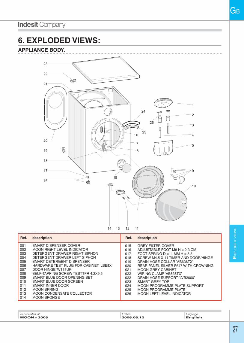
6. EXPLODED VIEWS:APPLIANCE BODY.
13
17
19
6
8
7
9
205
3
1
2
4
18
1214 11
1016
22
23
21
15
24
25
26
001 SMART DISPENSER COVER 002 MOON RIGHT LEVEL INDICATOR 003 DETERGENT DRAWER RIGHT SIPHON 004 DETERGENT DRAWER LEFT SIPHON 005 SMART DETERGENT DISPENSER 006 HARDWARE TEST PLUG FOR CABINET ‘LBE8X’007 DOOR HINGE ‘W133UK’ 008 SELF-TAPPING SCREW TESTTFR 4.2X9.5 009 SMART BLUE DOOR OPENING SET 010 SMART BLUE DOOR SCREEN 011 SMART INNER DOOR 012 MOON SPRING 013 MOON CONDENSATE COLLECTOR 014 MOON SPONGE
Ref. description
015 GREY FILTER COVER 016 ADJUSTABLE FOOT M8 H = 2.3 CM 017 FOOT SPRING D =11 MM H = 8.5 018 SCREW M4.5 X 11 TIMER AND DOOR/HINGE 019 DRAIN HOSE COLLAR ’AB636TX’ 020 REAR PANEL SILVER F647 WITH CROWNING 021 MOON GREY CABINET 022 WIRING CLAMP ‘AB636TX’ 022 DRAIN HOSE SUPPORT ‘LVB2000’ 023 SMART GREY TOP 024 MOON PROGRAMME PLATE SUPPORT 025 MOON PROGRAMME PLATE 026 MOON LEFT LEVEL INDICATOR
Ref. description

EX
PL
OD
ED V
IEW
S
28
GB
Service ManualMOON - 2006
LinguageEnglish
Edition2006.06.12
MOBILE ASSEMBLY.
1
2
3
4
5
6
7
8
9
18
19
20
21
23
22
11
13
14
12
5
17
10
16
1
15
24
001 SCREW X COUNTERWEIGHT/AQUALT. TUB003 TOP COUNTERWEIGHT VPL 12.5 KG AQUAL.004 AQUALTIS SPRING RING NUT 005 SMART TUB SPRING 006 PLASTIC TUB UNIT 52 L H=20 MM SMART007 SPRING REAR TENSION RING EVOII008 DOOR SEAL + SMART DISPENSER SUPPORT009 FRONT RING EVO II010 FRONT COUNTERWEIGHT VPL SMART011 OKO HOSE BALL EVO II012 HOSE CLAMP - TUB SIDE
Rif. descrizione
013 AQUALTIS FLEXIBLE DRAIN HOSE014 HOSE CLAMP - DRAIN PUMP SIDE 015 REMOVABLE DRUM BAFFLE 46L017 GASKET FOR OKO AQUAL FLEXIBLE DRAIN HOSE018 EXPANDER019 ROMOB NUT M6X20X1.6020 DAMPER 100 N021 DRIVEN PULLEY D=280 MM H=20 MM022 SCREW M8X23 TORX TEFL ROHS023 ELASTIC BELT 1194 J5 DIELECTRIC AQ024 DAMPERS 100 N KIT
Rif. descrizioneRif. descrizione Rif. descrizioneRef. description Ref. description

EX
PL
OD
ED V
IEW
S
29
GB
Service ManualMOON - 2006
LinguageEnglish
Edition2006.06.12
ELECTRICAL AND ELECTRONIC COMPARTMENTS.
001 THREE-LOBED SELF-TAPPING SCREW 3.5X8 DENT002 POWER SUPPLY CABLE .3X1 SCHUKO 1.5M+IND. FILTER003 WASHER-DRYER DRAIN PUMP004 CONTROL UNIT NO SMART PCB 005 SMART GREY BUTTONS KIT006 PRESSURE SWITCH 1 L. 85-60 ANTISPILL 330 SMART007 PRESSURE SWITCH HOSE CLAMP 008 PRESSURE SWITCH HOSE L=540 MM EVO II009 SMART STEAM VENT TUBE010 MICRODELAY SWITCH IDC 3 CONTACTS011 FIXING SCREWS FOR MOTOR/TUB012 COMMUTATOR MOTOR 1200 RPM P52 EVO2013 SMART SCREW CONDUCTIVITY SENSOR014 DRAIN PUMP 220-240V./50HZ AQUA
Rif. descrizione
015 ASKOLL/PLASET BAYONET PUMP FILTER KIT016 NTC TEMPERATURE SENSOR 017 HEATING ELEMENT 1700/230 VPL018 EEPROM SS1200SSTD EVO II SW 28412610000019 ELEC. MODULE .NO EEPROM STD ROHS ED. 3.0021 HOSE CLAMP 15.1-15.9022 SOL. VALVE HOSE CONDENSER L=63.6 CM GREY023 CURVED INLET HOSE 1500 MM ROHS024 SOLENOID VALVE 1E2U SMART025 DRAIN HOSE COLLAR026 INLET HOSE GASKET027 INLET HOSE FILTER028 SOLENOID VALVE SUPPORT 1 EV SMART
Rif. descrizioneRif. descrizione Rif. descrizioneRef. description Ref. description
HARDWARE
1
2
11
12
14
15
16
6
8
7
24
26
27
28
23
21
22
25
18
10
13
4
5
2019
7
17
22
21
9
29
3

EX
PL
OD
ED V
IEW
S
30
GB
Service ManualMOON - 2006
LinguageEnglish
Edition2006.06.12
light blue 0.35 X 1400light blue 0.35 X 1400
light blue 0.35 X 1400light blue 0.35 X 1400
G/V 1.0 X 240
G/V 1.0 X 1190TG6
TM
TR
Display
ASSEMBLY L= Motor+pump
RED 0.50 X 1580BROWN 1.00 X 1580
BROWN 1.00 X 1580
light blue 0.35 X 780light blue 0.35 X 780
Filt
er
Press.
PCB
R.R.
lav
Ntc
EVL
EVP
RST2,5ED
GP
CB
ASSEMBLY A
J1
J3
J9
ASSEMBLY B1 = DISPLAY COMMUNIC.
J8
ASSEMBLY C1 = EVL+EVP
PC
B
J4
ASSEMBLY D = Microdelay
BLACK 0.75 X 520
RED 0.50 X 520
RED 0.50 X 520
BLACK 0.75 X 520BLACK 0.75 X 520BLACK 0.75 X 520BLACK 0.75 X 520W
ash
mot
orPS
BLUE 1.00 X 500
FA4FA1
1J12J1
P16P11P14P12
1J92J93J94J95J96J97J98J99J9
1J42J43J4
MRC
MRL
MRN
R.TF.
R.R.
1J112J113J114J115J11
J11
Com
unic
.
RST 2,5 EDGPCB
1J15
2J153J15
4J155J15
-4-
-3-
-2-
-1-
-2-
-1-
-1-
-2-
-3-
-1-
-2-
-3-
-4-
-5-
-6-
-7-
L/NPCB
1J32J33J34J35J36J3
1J8
3J8
4J8
6J8
7J8
9J8
12J8
EDGRST 5PCB
11J8
BLUE 1.00 X 940BROWN 1.00 X 940
RED 0.50 X 1250BLUE 1.00 X 1250BROWN 1.00 X 1250BLUE 1.00 X 1250BROWN 1.00 X 500
RED 0.50 X 510
RED 0.50 X 510
ASSEMBLY X = MACHINE EARTH STD
white 0.35 X 1390
white 0.35 X 1390celeste 0.35 X 1390
light blue 0.35 X 1390
light blue 0.35 X 1400
1
3
1
3
1
3
BLACK 0.75 X 840BLUE 1.00 X 680
ASSEMBLY I = CONDUCT.SENS.
S.CT.G6
1J5
2J5J5

Indesit Companyviale Aristide Merloni, 47
60044 Fabriano - Italy
tel. +39 0732 66 11 - telex 560196 - fax +39 0732 66 2954 - www.indesitcompany.com
Service ManualMOON - 2006
LinguageEnglish
Edition2006.06.12
GB