Presentazione di PowerPoint - Indesit...
58
0 60 cm Platform Partial No Frost & Clever 1.0 Appliances 2015 Event: Ca’Maiano, May 2015 Presenter: Francesco Nieli Francesco Licco
-
Upload
duongthuan -
Category
Documents
-
view
223 -
download
4
Transcript of Presentazione di PowerPoint - Indesit...

0
60 cm Platform
Partial No Frost &
Clever 1.0 Appliances
2015
Event:Ca’Maiano, May 2015
Presenter:
Francesco Nieli
Francesco Licco

1
Partial No Frost Appliances
with mechanical thermostat
and defrost timer
Operating Logic

Logic
2
Legend
Product with single adjustment mechanical thermostat. The
refrigerator compartment temperature is set/adjusted by the knob.
The freezer compartment is cooled accordingly.
Turn the knob clockwise to set lower temperatures and, on the
contrary, turn the knob counterclockwise to set higher
temperatures.

Defrost logic
3
The defrost takes place through an appropriate TIMER.
The time between two defrost cycles depends only on the time of the last
compressor ON:
• If the duration of the last Comp. ON < 2h prox. defrost at 22h of Comp. ON
• If the duration of the last Comp. ON > 2h prox. defrost at 12h of Comp. ON
Important: if, when 12 hours are reached, the last Compressor ON duration was less
than 2 hours, the Compressor ON duration is monitored and if it should exceed 2 hours
the defrost will be made before the expiry of the 22 Compressor ON hours.
Defrost End:• When a temperature of +20°C is reached
• Maximum defrost time: 60 minutes

Forced defrost
4
It is possible to start a forced defrost with the following procedure:
With appliance on and in operation (temperature knob in a position other
than off):
Disconnect twice the power plug for a time NOT less than 5 seconds and
keep it plugged in for a time NOT more than 3 seconds. The third time the
plug is inserted the defrosting process will start automatically.
Defrost procedure
5
The defrosting occurs as follows:
1. All loads are switched off (there is no cooling request)
2. The defrosting heaters remain on until a temperature of + 20 °C is
reached or at the 60 minute Time Out.
3. An 8 minute pause is made to drain the remaining water
4. The appliance starts operating normally again

6
Components

Timer
7
The defrost takes place through an appropriate TIMER.
The time between two defrost cycles depends only on the time of the last
compressor ON:
If the duration of the last Comp. ON < 2h prox. defrost at 22h of Comp. ON
If the duration of the last Comp. ON > 2h prox. defrost at 12h of Comp. ON
It is located on the dashboard of the product
TIMERTHERMOSTAT
PNF components with Timer
8
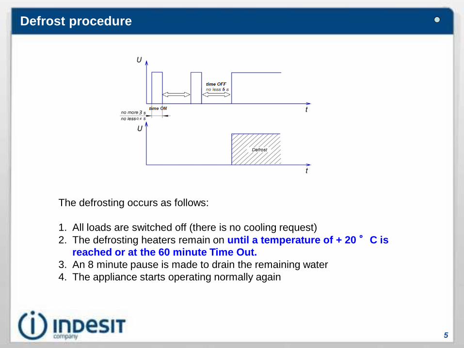
Double Thermal Fuse:Thermal protection components that opens if the thermal-protector does not
operate.
Thermal-protector:Component used to control the defrost end. Once the temperature of + 20°C
is reached, the heating elements will switch off.

PNF BASE and CLEVER Components
9
Refrigerator air fan:This component is switched on and off through the internal
button.
It is activated in parallel with the compressor ON even if the
fridge compartment door is opened.
Freezer air fan:It is turned on and off with the
compressor.
Nominal tension: 220 – 240 Volt
Frequency: 50 / 60 Hz
Nominal power: 3.5 W
RPM: 1200 +/- 100 U/1’
Insulating class: B

Components technical data
10
Component DescriptionHeater Technology
[Distributed, Foil, Calrod]
Nominal Power
[W]
Nominal Tension
[V]
EVAPORATOR HEATING ELEMENTSilicone Hoseinside an
Aluminum tube diameter 4.5mm
105 220
Gutter HeaterHose
on a 0.06mm adhesivized aluminum sheet
30 220

11
Air flow

Fridge compartment air flows
12
Appliance with fan and
without Multiflow
Appliance with fan and
with Multiflow
Freezer compartment air flow
13
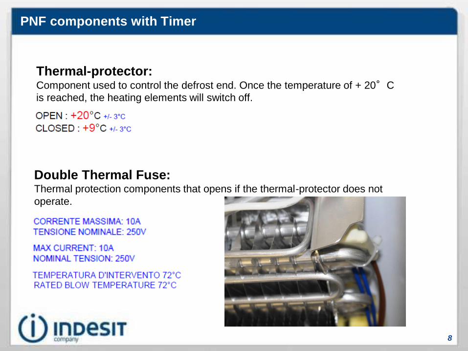
In the freezer, air is pushed by the fan and sent to the compartment through the slots of the
bottom plate (in the back - blue arrows) to then return back through the front grids (red arrows)
and be cooled again forcing the passage of air through the evaporator.
14
Appliance Improvement

General improvements to the project
15
Current:
New:
While the freezer fan is ON, it creates a vacuum in thedrain tube which causes a suction of air from outside.Hot air rich in humidity goes up from the drain tubecoming directly into contact with the freezer fan bladeswhich have a very low temperature. This causes theformation of ice and consequent freezer fan noise untilit stops.
The presence of the siphon creates a water head inthe drain tube, which eliminates all the hot air inputsfrom the outside, eliminating the presence of ice onthe blades of the freezer fan.

16
Electrical Wiring Diagram
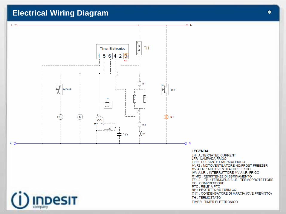
Electrical Wiring Diagram
17
18
Disassembly

Removing the evaporator
19
Unscrew the 3 screws on the front
upper part of the freezer
compartment
Unscrew the 6 screws of the
multiflow freezer bottom and
remove it pulling it from the front

20
Removing the evaporator
Carefully lower the front part of the
gutter, pivoting on the drain
Pull the gutter frontally but not
totally since the gutter heater is still
connected
Note: be careful not to break the
polystyrene cover

21
Removing the evaporator
Disconnect the gutter heater and
pull out the tray completely
Unscrew the two lateral screws
and remove the motor fan and the
related cable.

22
Partial No Frost Appliances
with Clever 1.0
Electronic Board
Operating Logic
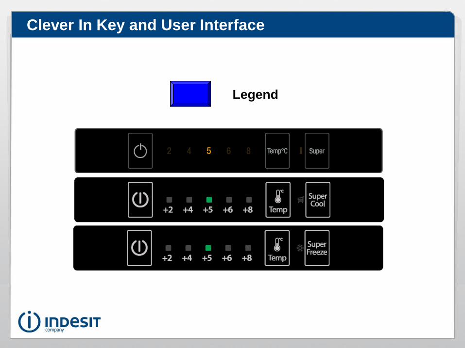
Clever In Key and User Interface
Legend

Clever Out User Interface

Compartment temperature control
25
For products with Fridge adjustment only: the
product has 5 levels of temperature control, which are: +8; +6; +5; +4;+2; in scrolling order we re-start from the beginning (cyclic). Bypressing the dedicated button, the temperature will change until itreaches the desired temperature.Also the product On/Off button and the Super Fridge o Super Freezeraccording to the model button are available.

Functions
26
The Super Fridge and Super Freeze functions or Super or (Quick Freeze for Hotpoint) CANNOT beavailable simultaneously on the same User Interface. It is possible to have only one of theseoptions since the Clever products - at the present- have the control of a single compartment andonly one button is available on the User Interface.
Super Fridge / Push & Cool function :The function is activated by operating the related button.It serves to quickly cool a large amount of food placed in the refrigerator compartment.This function takes 12 hours and turns off automatically at the end of this time or ifswitched off by the Super Fridge button.A Black Out or deactivating the electrical outlet do not cancel the function if it has beeninserted previously.
Super Freeze / Super Function:The function is activated by operating the related button.It is used to quickly freeze foods placed in the freezer compartment.If the Compressor On cumulative time is less than 3 hours when this function isactivated, it starts immediately otherwise the function starts with a defrost after whichthe Super Freeze phase begins.The function is deactivated automatically at the end of 24 hours (duration of thefunction) or if switched off through the Super Freeze button.A Black Out or deactivating the electrical outlet do not cancel the function if it has beeninserted previously.

Functions
27
How the Super Freeze / Super works in Partial NoFrost appliances:The function is controlled by the Fridge Evaporator Probe, since the Freezer Air Probe isnot available.When the function is activated, the compressor starts and the Fridge compartmenttemperature is controlled at a temperature of +2°C similar to a normal Super Fridge.The function lasts the usual 24 hours and unlike the normal Super Freeze, thecompressor will be switched on and off according to the fridge temperature control(between +2°C (compressor stop) and +4°C (compressor start)).
28
Components

Components
29
Temperature probe:The temperature probes manage and control the
compressor On/Off or defrost termination depending on the
type of product.
The probes are NTC and can be checked using the table
here aside.
The probes available in these products are:
• Fridge evaporator
• Freezer evaporator
In case of malfunction of the Fridge Evaporator probe it is
possible to proceed with the cutting and accurate
isolation of the wiring of the probe in question. The
product will work on time using the appropriate tables in
memory.

Components
30
Temperature probe:
In case of malfunction of the Freezer Evaporator Probe,
You must replace the probe following the technical Bulletin
instructions.
Technical Bulletin
Important: Only in case of wiring sensor is
interrupted in the foamed zone, cut it and insolate it very
well. The product will work using internal time references.
PNF Clever Components
31
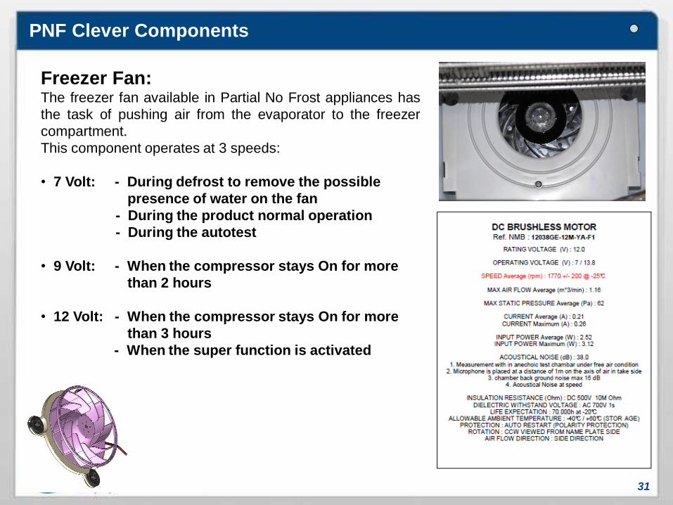
Freezer Fan:The freezer fan available in Partial No Frost appliances has
the task of pushing air from the evaporator to the freezer
compartment.
This component operates at 3 speeds:
• 7 Volt: - During defrost to remove the possible
presence of water on the fan
- During the product normal operation
- During the autotest
• 9 Volt: - When the compressor stays On for more
than 2 hours
• 12 Volt: - When the compressor stays On for more
than 3 hours
- When the super function is activated

PNF Clever Components
32
Fridge Fan:The fridge fan compartment has the function to uniformly distribute
cold air inside the compartment.
To enable or disable the fan fridge it is necessary to turn it on using
the small button located inside the compartment.
When it works: always with the Compressor ON since they are
connected in parallel.
It does not turn off with the door opening.
Nominal tension: 220 – 240 Volt
Frequency: 50 / 60 Hz
Nominal power: 3.5 W
RPM: 1200 +/- 100 U/1’
Insulating class: B
Double Thermal Fuse:Thermal protection components that intervene in case of malfunction of any control
component such as the main board, NTC, etc.
PNF Clever Components
33
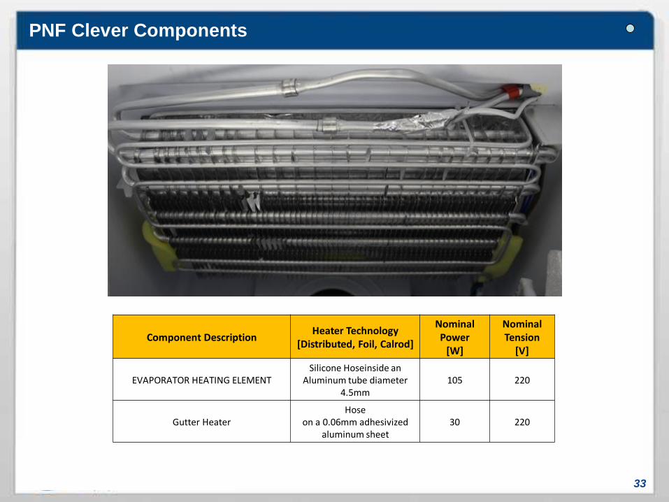
Component DescriptionHeater Technology
[Distributed, Foil, Calrod]
Nominal Power
[W]
Nominal Tension
[V]
EVAPORATOR HEATING ELEMENTSilicone Hoseinside an
Aluminum tube diameter 4.5mm
105 220
Gutter HeaterHose
on a 0.06mm adhesivized aluminum sheet
30 220

34
Operating Logic
Door Open Alarm
35
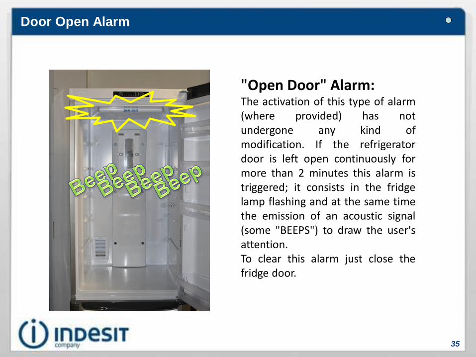
"Open Door" Alarm:The activation of this type of alarm(where provided) has notundergone any kind ofmodification. If the refrigeratordoor is left open continuously formore than 2 minutes this alarm istriggered; it consists in the fridgelamp flashing and at the same timethe emission of an acoustic signal(some "BEEPS") to draw the user'sattention.To clear this alarm just close thefridge door.
Alarm A1 & A2 mechanical device
36

37
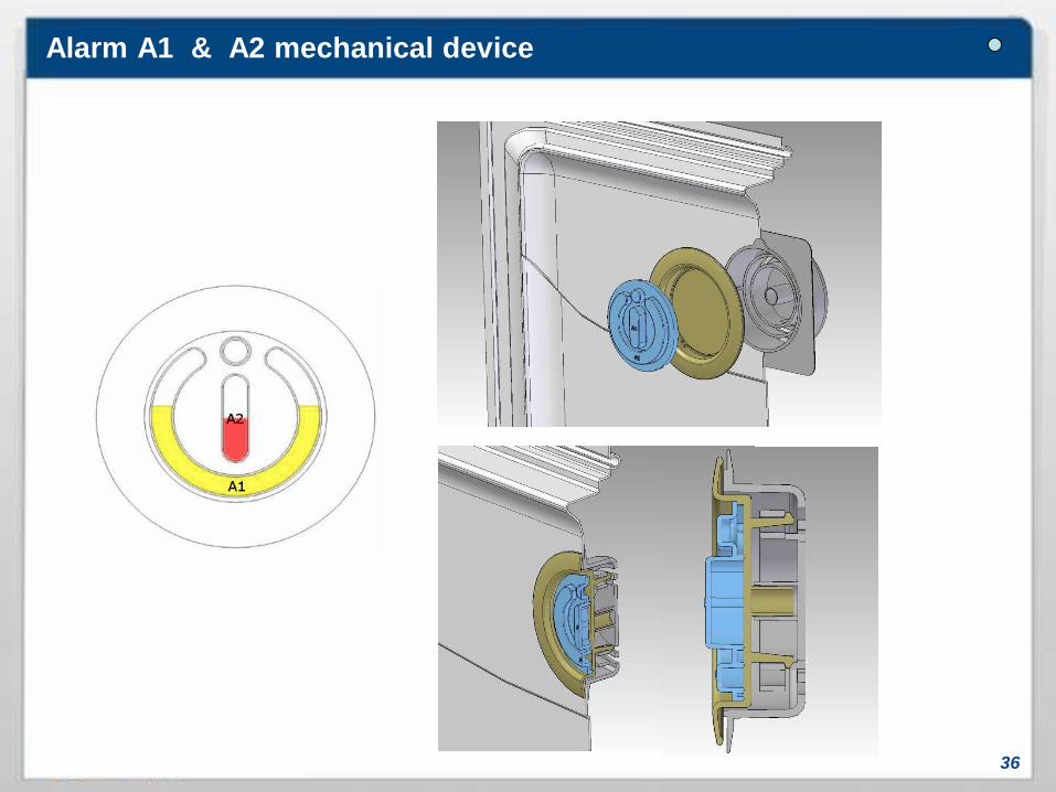
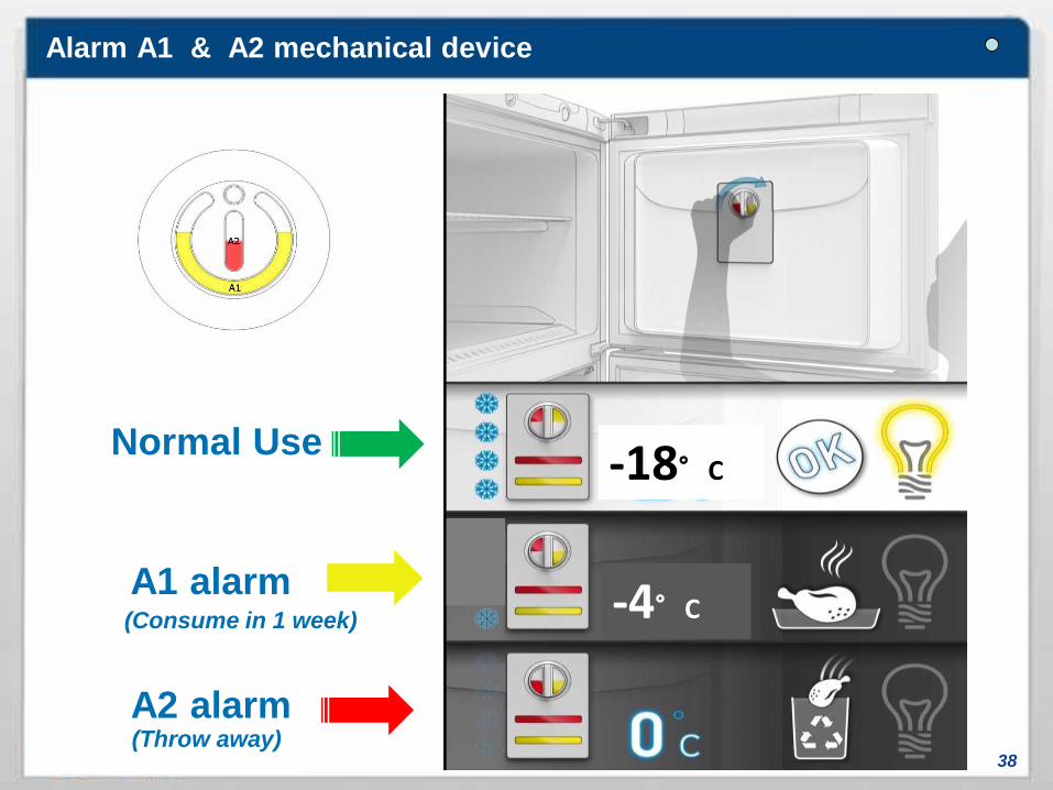
Alarm A1 and A2:These alarms are NO managed by the MainBoard and the Freezer Air Probe.A manual device, that will indicate if therehave been increases in the temperature,has been added behind the freezer door.How it works:1. Turn over the Alarm symbol (as shownin fig. 1) and leave it so for 24 hours, untilthe liquid freezes.2. After this time, reposition it (fig. 2) in itsnormal position.3. If one or both of the liquid melt it meansthat the temperature inside the freezer isabove the safety threshold (fig. 3).
Temperature thresholds:
•A1: -4°C (yellow liquid)•A2: 0°C (red liquid)
Fig. 1
Fig. 2
Fig. 3
Alarm A1 & A2 mechanical device
38
-18°C
-4°C
Normal Use
A1 alarm
A2 alarm
(Consume in 1 week)
(Throw away)
Alarm A1 & A2 mechanical device
Forced defrost
39
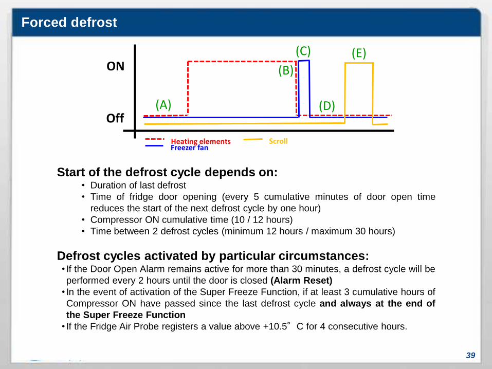
Start of the defrost cycle depends on:• Duration of last defrost
• Time of fridge door opening (every 5 cumulative minutes of door open time
reduces the start of the next defrost cycle by one hour)
• Compressor ON cumulative time (10 / 12 hours)
• Time between 2 defrost cycles (minimum 12 hours / maximum 30 hours)
Defrost cycles activated by particular circumstances:• If the Door Open Alarm remains active for more than 30 minutes, a defrost cycle will be
performed every 2 hours until the door is closed (Alarm Reset)
• In the event of activation of the Super Freeze Function, if at least 3 cumulative hours of
Compressor ON have passed since the last defrost cycle and always at the end of
the Super Freeze Function
• If the Fridge Air Probe registers a value above +10.5°C for 4 consecutive hours.
ON
Off(A)
(B)
(C) (E)
(D)
Heating elementsFreezer fan
Scroll
Defrost
40
ON
Off(A)
(B)
(C) (E)
(D)
Heating elementsFreezer fan
Compressor
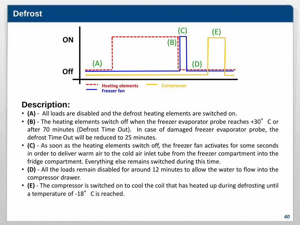
Description:• (A) - All loads are disabled and the defrost heating elements are switched on.• (B) - The heating elements switch off when the freezer evaporator probe reaches +30°C or
after 70 minutes (Defrost Time Out). In case of damaged freezer evaporator probe, thedefrost Time Out will be reduced to 25 minutes.
• (C) - As soon as the heating elements switch off, the freezer fan activates for some secondsin order to deliver warm air to the cold air inlet tube from the freezer compartment into thefridge compartment. Everything else remains switched during this time.
• (D) - All the loads remain disabled for around 12 minutes to allow the water to flow into thecompressor drawer.
• (E) - The compressor is switched on to cool the coil that has heated up during defrosting untila temperature of -18°C is reached.

41
General Improvement
For all products of this 2015
platform

Fridge compartment air flows
42
Appliance with fan and
without Multiflow
Appliance with fan and
with Multiflow

Freezer compartment air flow
43
In the freezer, air is pushed by the fan and sent to the compartment through the slots of the
bottom plate (in the back - blue arrows) to then return back through the front grids (red arrows)
and be cooled again forcing the passage of air through the evaporator.

General improvements to the project
44
Current:
New:
While the freezer fan is ON, it creates a vacuum in thedrain tube which causes a suction of air from outside.Hot air rich in humidity goes up from the drain tubecoming directly into contact with the freezer fan bladeswhich have a very low temperature. This causes theformation of ice and consequent freezer fan noise untilit stops.
The presence of the siphon creates a water head inthe drain tube, which eliminates all the hot air inputsfrom the outside, eliminating the presence of ice onthe blades of the freezer fan.
45
Wiring Diagrams

Combi PNF Clever In wiring diagram
46
Remember to ALWAYS unplug the appliance
from the electrical supply before any operation
on the UI or Main Board.
PNF Combi appliances with Clever Out Board
will have the UI connector in this position.
Remember that in order to re-program these
appliances it is necessary to disconnect the UI
and connect the Hardware Key in the same
point.
47
Serviceability

Forced defrost
48
Demo Mode:Not available with these products
Autotest:
For the Activation:Starting from the product off, press the Super Freeze (Quick Freeze) or Super Cool (Cool Speed)
button, depending on the option on the product, for 6 seconds.
All LEDs will be lit simultaneously for 2 seconds and at the same time an acoustic signal of the
same duration will be heard. Then the Autotest sequence will start.
Note: If there is a “Last Fault” this will be displayed for 15/20 seconds, after 2 seconds of LEDs
lighting on and before starting the control sequence. The Last Fault only clears at the end of the
Autotest sequence.
For the output:• Automatically at the end of the Autotest. At the end of the Autotest the appliance goes back to
"OFF".
• By switching on the appliance (using "On/Off"button).
• Unplugging the appliance from the electrical supply.

Combi PNF Products Autotest
49
Step Duration Action Light Notes
1 6 seconds FZ fan ON
Defrost heating element ON
OFF
2 20 seconds Show last fault OFFIf there are no faults in memory go
directly to step 3
3 1 seconds Pause OFF
4 1 second Probe check OFF
If the probe test is OK
the sequence skips to step 6.
If there is a fault with the probes KO
the sequence skips to step 7.
5 1 seconds Pause OFF
6 125 seconds FZ fan ON
Defrost heating element ON ON After this test, it skips to step 8.
7 125 seconds FZ fan ON
Defrost heating element ON Blinking
8 3 seconds All leds and buzzer on OFF
9 End of Autotest.

Fault table
50
Important: The Faults are shown by using the Binary Encoding from left to right or
from bottom to top depending on the User Interface.Refers to the SQG_CL_39 (Clever Fault Table).The Faults will be visible only through Autotest and will no longer be visible in thenormal operation of the product.

51
Programming
Programming Clever Out Board
52
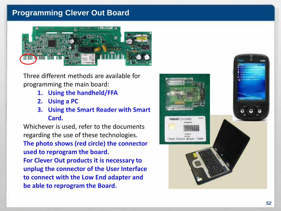
Three different methods are available for programming the main board:
1. Using the handheld/FFA2. Using a PC3. Using the Smart Reader with Smart
Card.Whichever is used, refer to the documents regarding the use of these technologies. The photo shows (red circle) the connector used to reprogram the board.For Clever Out products it is necessary to unplug the connector of the User Interface to connect with the Low End adapter and be able to reprogram the Board.

Programming Clever In Board
53
Three different methods are available for programming the main board:
1. Using the handheld/FFA2. Using a PC3. Using the Smart Reader with
Smart Card.Whichever is used, refer to the documents regarding the use of these technologies. The photo shows (red circle) the connector used to reprogram the board.

54
Disassembly
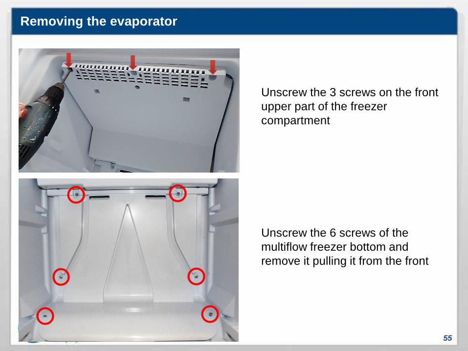
Removing the evaporator
55
Unscrew the 3 screws on the front
upper part of the freezer
compartment
Unscrew the 6 screws of the
multiflow freezer bottom and
remove it pulling it from the front

56
Removing the evaporator
Carefully lower the front part of the
tray pivoting on the drain
Frontally pull the tray but not
completely as the gutter heater is
still connected. Be careful not to
break the polystyrene cover
57
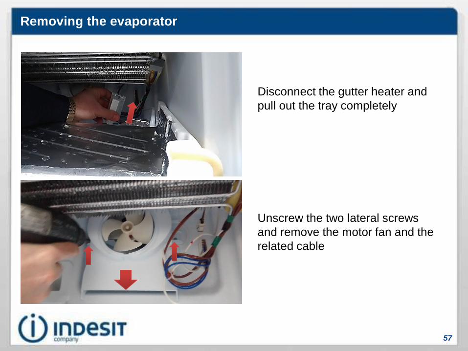
Removing the evaporator
Disconnect the gutter heater and
pull out the tray completely
Unscrew the two lateral screws
and remove the motor fan and the
related cable