Service Information - Indesit Company -...
29
Indesit Company UK Ltd © 2013 Reg. Office: Peterborough PE2 9JB Registered in London: 106725 Service Information Indesit Washing Machine Arcadia Platform Model Commercial Covered: Code IWE91281ECOUK 80133 5407770 Issue 1 Aug. 2013 SM003786 ~ C00300890
Transcript of Service Information - Indesit Company -...

Indesit Company UK Ltd© 2013 Reg. Office: Peterborough PE2 9JB Registered in London: 106725
ServiceInformation
IndesitWashingMachine
ArcadiaPlatform
Model CommercialCovered: Code
IWE91281ECOUK 80133
5407770 Issue 1 Aug. 2013
SM003786 ~ C00300890

2 of 29
Service Manual UK
Indesit Company
English
SAFETY NOTES & GENERAL SERVICING ADVICE1. This manual is NOT intended as a comprehensive repair/maintenance guide to the appliance.2. It should ONLY be used by suitably qualified persons having technical competence applicable
product knowledge and suitable tools and test equipment.3. Servicing of electrical appliances must be undertaken with the appliance disconnected (unplugged)
from the electrical supply.4. Servicing must be preceded by Earth Continuity, Earth Resistance & Insulation Resistance checks.5. Personal safety precautions must be taken to protect against accidents caused by sharp edges on
metal and plastic parts.6. After servicing the appliance must be rechecked for Electrical Safety. In the case of appliances
which are connected to a water supply (i.e.: Washing Machines, Dishwashers & Food Centres etc.) checks must be made for leaks from seals gaskets and pipe work and rectification carried out where necessary.
7. It can be dangerous to attempt 'DIY' repairs / maintenance on complex equipment and the Company recommends that any problem with the appliance is referred to its own Service Organisation.
8. Whilst the Company has endeavoured to ensure the accuracy of the data within this publication they cannot hold themselves responsible for any inconvenience or loss occasioned by any error within.
IMPORTANT SAFETY NOTE
Risk of Electric ShockThe metal heatsink fitted on thePower Module may hold an electrical charge for a short period after switching off the machine.Allow 5 minutes after disconnecting the machine from the electrical supply before commencing ANY work.

3 of 29
Indesit Company
Service Manual UK English
SERIAL NUMBER / INDUSTRIAL CODE EXPLANATION
Model Number Definition
Category Interface CapacitySpinSpeedRPM
OtherEnergyEfficiencyClass
Colour Software
I = Indesit Eco TimeW = WasherWD = Washer DryerS = SlimU = Super Slim
A = 1 Knob LEDB = 2 Knobs LEDC = 3 Knobs LEDD = Small DigitE = Big Digit
4 = 4 KG5 = 5 KG6 = 6 KG7 = 7 KG8 = 8 KG9 = 9 KG
10 = 1000 11 = 1100 12 = 1200 13 = 1300 14 = 1400 15 = 1500 16 = 1600
3 = Tactical5 = Range8 = Tri Phase
0 = A 1 = A -10%2 = A -20%
B = Bi ColourK = BlackS = Silver
E =Arcadia2
Serial Number Example2 07 02 0895
Four remaining digits = Build number that day 895th builtThird two digits = Day of manufacture 2nd of monthSecond two digits = Month of manufacture JulyFirst digit = Year of manufacture 2012
Industrial Code Example30 78833 0000
Last four digits = 0000 original production.
Second five digits = COMMERCIAL CODE*
First two digits = Factory of origin* Vital for correct model information and system identification
Other numbers denote major production changes
INDESITEcoTime
Washer Big Digit 9 kg 1200 rpm Tri-phase Class 1A -10%
ECO MarketCountry
I W E 9 12 8 1 ECO UK

4 of 29
Service Manual UK
Indesit Company
English
INDEX
Safety Notes, Servicing & Serial Number Information . . . . . . . . . . . . . . . . . . . . . . . . . . . .2 - 3Model Definition . . . . . . . . . . . . . . . . . . . . . . . . . . . . . . . . . . . . . . . . . . . . . . . . . . . . . . . . . . . . . 3Technical Information . . . . . . . . . . . . . . . . . . . . . . . . . . . . . . . . . . . . . . . . . . . . . . . . . . . . . . . . 5Introduction / Production History . . . . . . . . . . . . . . . . . . . . . . . . . . . . . . . . . . . . . . . . . . . . . . . 6Installation . . . . . . . . . . . . . . . . . . . . . . . . . . . . . . . . . . . . . . . . . . . . . . . . . . . . . . . . . . . . . . .7 - 8Controls / Options / Special Wash Cycles . . . . . . . . . . . . . . . . . . . . . . . . . . . . . . . . . . . . .9 - 12Auto Test / Loading Detergent . . . . . . . . . . . . . . . . . . . . . . . . . . . . . . . . . . . . . . . . . . . . . . . . 13Wash Programmes . . . . . . . . . . . . . . . . . . . . . . . . . . . . . . . . . . . . . . . . . . . . . . . . . . . . . . . . . 14 New Components / Controls Information . . . . . . . . . . . . . . . . . . . . . . . . . . . . . . . . . . . . . . . 15Main Board Programming Methods . . . . . . . . . . . . . . . . . . . . . . . . . . . . . . . . . . . . . . . . .16 - 17 Wiring Diagram . . . . . . . . . . . . . . . . . . . . . . . . . . . . . . . . . . . . . . . . . . . . . . . . . . . . . . . . . . . . . 18Wiring Connections . . . . . . . . . . . . . . . . . . . . . . . . . . . . . . . . . . . . . . . . . . . . . . . . . . . . . . . . . 19Power Module Connections. . . . . . . . . . . . . . . . . . . . . . . . . . . . . . . . . . . . . . . . . . . . . . . . . . . 20Fault Identification / Fault Codes / Fault Finding. . . . . . . . . . . . . . . . . . . . . . . . . . . . . . .21 - 25Dismantling Procedure . . . . . . . . . . . . . . . . . . . . . . . . . . . . . . . . . . . . . . . . . . . . . . . . . . 26 - 28

5 of 29
Indesit Company
Service Manual UK English
TECHNICAL INFORMATION
Models Covered Indesit: IWE91281ECOUK (80133)
Colour White
Dimensions Height: 850 mmWidth: 595 mmDepth: 600 mm
Weight Nett. 73.4 KgGross: 75.0 Kg
Country of Origin Poland - Radomsko Factory (30)
Electrical Supply 220 / 240 Volts AC @ 50Hz
Energy Consumption
Energy Class A+
Washing Performance Class: A
Water remaining after Spin Cycle 53%
Spin Efficiency Class B
Features Full wash (9 Kg) Daily Wash, 20° Zone Programmes, Sport andSpecial Programmes, Delay Start Timer. Eco Time, Energy Saver, Extra Rinse and Easy Iron options. Variable
Temperature, Variable Spin.
Wash Heater 1700 Watt @ 230V - 31
Temperature Sensor (drum rear) 20 k @ 20°C
Pump Askoll 220-240 Volt AC 50Hz, 30 Watt, 0.2A 169
Wash Motor 3 phase Induction - CIM 2/55 132/AD6 - 195v - 3.7A - 800W -290Hz -17500 rpm - Insulation class F
Tacho = 115.4
Weight = 5.8 Kg
Tank Assembly (Outer Drum) Plastic, 62 litres
Water Connection Cold Fill
Water Pressure Min : 0.05 MPA (0.5 bar), Max: 1.0 MPA (10.0 bar)
Annual Energy Consumption of 220 cycles based on Cotton 60° Full Load and Cotton 40° Half Load
278kWh
Energy Consumption on 60°C Full Load 1.551 kWh
Energy Consumption on 60°C Half Load 1.03 kWh
Energy Consumption on 40°C Half Load 0.92 kWh

6 of 29
Service Manual UK
Indesit Company
English
INTRODUCTION
This range of washing machines is designed to save time without compromising the effectiveness of their performance.Maximum Wash Load = 9 KgDisplay User Interface - Big Digit- keeps the user informed of the progress of the Programme, plus in the unlikely event of a fault developing, the display will also indicate the service fault code, allowing speedy fault diagnosis.Special ProgrammesThe machine has 'Special’ and 'Sports' programmes in addition to the normal choice of fabric programmes clearly marked on the controls.The OKO Detergent Recovery system is used making full use of the washing powder with no wastage.Demo Mode is not available on these models.Energy Rated programmes according to regulation EN60456.Wash: Programme 1 temperature 60°C using a load of 9 Kg.First Wash Cycle: (Maintenance Wash).Once the appliance has been installed, and before using it for the first time, run a wash cycle with detergent, but without laundry at 90°C.STAND-BY ModeThe machine in compliance with the new ’Energy Saving Regulations’ is fitted with an automatic stand-by system which is enabled after 30 minutes if no activity is detected. Press the On/Off button briefly and wait for the machine to start up again.Consumption in Off Mode: 0.5WConsumption in Left On Mode: 0.5W
Production HistoryModel: IWE 91281 ECOUKCommercial Code: 80133Industrial Code: 30801330000Location: Radomsko Factory (30) PolandFirst Produced: June 2012Type: 3 Phase / Arcadia 2

7 of 29
Indesit Company
Service Manual UK English
INSTALLATION
Unpacking1. Unpack the washing machine.2. Check whether the washing machine has been damaged
during transport. If this is the case, do not install it and contact your retailer.
3. Remove the four protective screws and the rubber washer with the respective spacer, situated on the rear of the appliance (see Figure right).
4. Seal the gaps using the plastic plugs provided.5. Use the plug provided to seal the three holes where the
plug was housed, situated on the lower right hand side on the rear of the appliance.
6. Keep all the parts as they will be required again if the washing machine needs to be moved to another location.
Levelling1. Install the washing machine on a flat sturdy floor, without resting it up against walls, cabinets etc.2. Compensate for any unevenness by tightening or loosening the adjustable front feet. The angle of inclination, measured according to the worktop must not exceed 2°.Levelling your appliance correctly will provide it with stability and avoid any vibrations, noise and shifting during operation. If it is placed on a fitted or loose carpet, adjust the feet in such a way as to allow enough room for ventilation beneath the washing machine.
Water ConnectionsConnecting the water inlet hose.
! Check that seal is in place inside the hose end cap.
Connect the other end of the water inlet hose to the washing machine, screwing it onto the cold water inlet, situated on the top right-hand side on the rear of the appliance - see illustration.
Before making the water connection to 3/4" thread, allow the water freely from the supply tap until it is perfectly clear.
!Screw the inlet end with the blue cap onto the cold water supply tap.Turn the tap on and check for leaks: tighten if necessary.! Make sure there are no kinks or bends in the hose.! The water pressure at the tap must be within the values indicated in the Specifications page.! If the inlet hose is not long enough, contact a specialised shop or an authorised technician.! Never use second hand hoses - use the hoses supplied with the machine.

8 of 29
Service Manual UK
Indesit Company
English
DRAINAGE CONNECTIONS
A. Connect the drain hose, without kinking it, to a draining duct or a wall drain fixed at a height between 65 and 100 cm from the floor. See Fig.1.
B. Alternatively, place it over the edge of a basin, sink or tub, fastening the hose supplied to the tap.See Fig.1.The free end of the hose should not be under water.Note: We advise against the use of hose extensions. In case of absolute need, the extension must have the same diameter as the original hose and must not exceed 150 cm in length.
Undersink Connections: The drain hose may be connected to an undersink trap. Before connecting the drain hose from the machine ensure that any blanks or removable ends have been taken off the spigot. See Fig. 2.We advise against the use of hose extensions; in case of absolute need, the extension must have the same diameter as the original hose and must not exceed 150cm in length.
Electrical ConnectionsBefore plugging the appliance into the mains socket, make sure that:- the socket is earthed and in compliance with the applicable law.- the supply voltage is included within the values indicated in the Specifications page.- the socket is compatible with the washing machines plug. If this is not the case, replace the socket or the plug.
! - the socket is able to sustain the appliance’s maximum power load indicated on the Technical Data plate fixed on the machine.
Location! The washing machine should not be installed in an outdoor environment, not even when the area is
sheltered, because it may be very dangerous to leave it exposed to rain and thunderstorms.! When the washing machine is installed, the mains socket must be within easy reach.! Do not use extensions or multiple sockets.! The power supply cable must never be bent or dangerously compressed.! The power supply cable must only be replaced by an authorised serviceman.
WARNING!The company denies all liability if and when these warnings are not respected.
The first wash cycleOnce the appliance has been installed and before you use it for the first time, run a wash cycle without detergent and no laundry, setting the 90°C programme without a pre-wash cycle.
Fig.1
Fig.2

9 of 29
Indesit Company
Service Manual UK English
CONTROLS
Wash Cycle KnobSelects the required wash cycle.Once the programme has started, turning the control knob does not affect the progress of the originally selected wash cycle. The control knob does not move during the cycle.
Display
The Display advises the user of:Section A will indicate the duration of the available programme and the remaining time of the running programme. Section B will indicate the phases scheduled for the selected cycle and will indicate the current programme position once the cycle has commenced.Section C will indicate Temperature , Delayed Start , and Spin .If the symbol lights up the display will show the temperature.The symbol lights up while the Delayed Start has been set. If the symbol lights up the display will show the Spin Speed.
Door Locked Symbol When lit - the door is locked. Wait until the light turns off before opening the door. To open the door while the cycle is in progress, press the Start/Pause button; an audible clunk will be heard when the door locks - 2 clunks when the door is unlocked as the interlock disengages.Delay Time Remaining - if set.
Wash. Rinse. Spin. Drain.

10 of 29
Service Manual UK
Indesit Company
English
WASH OPTIONS
Selecting this option adjusts the drum rotation, Temperature and Water to a reduced load of lightly soiled cotton and synthetic fabrics 'ECOTIME' enables you to wash in less time saving water and electricity. It is recommended that liquid detergent is used when using this option.Not available with 1, 6, 7, 8, 9, 10, 11, 12, 13, 14, programmes.
Energy Save OptionThe function saves energy by not heating the water used to wash your laundry - an advantage both to the environment and to your energy bill. Instead, intensified wash action and water optimisation ensure great wash results in the same average time of a standard cycle.For the best washing results we recommend the usage of a liquid detergent.! It cannot be used with the 6, 7, 8, 10, 12, 13, 14, programmes.
Easy IronSelecting this option will modify the wash and spin cycles to reduce the formation of creases.At the end of the cycle the appliance drum will slowly rotate, the Easy Iron and Start / Pause option LEDs will flash – the first one Green and the second one Orange. To complete the cycle press the Start / Pause or Easy iron button.When using this option with programme 9 (Outwear), the programme will end with the load being held in water (Rinse Hold) with the Easy Iron and Start / Pause LEDs flashing. To drain the water so that the laundry load can be removed – Press either the Start / Pause or the Easy Iron button.Not available with 8, 10, 12, 13, 14, programmes.
Delay Start (Maximum 24 hours)To set the delayed start for the selected cycle, press the button repeatedly until the required delay time is reached.When the option is activated the indicator LED will remain lit.To remove the Delayed start time setting – Press the button until the text “OFF” appears on the display. This option can be used with all cycles.Note: Delayed time can be set from 30 minutes through to 24 hours:0:30 – 1:00 – 1:30 – 2:00 – 2:30 – 3:00 – 3:30 – 4:00 – 4:30 – 5:00 – 5:30 – 6:00 – 6:30 – 7:00 – 7:30 – 8:00 – 8:30 – 9:00 – 9:30 – 10h – 11h – 12h – 13h – 14h – 15h – 16h – 17h – 18h – 19h – 20h – 21h – 22h – 23h – 24h - OFF.
Extra RinseBy selecting this option the efficiency of the rinse is increased, and optimal detergent removal is guaranteed. It is particularly for sensitive skin.Not available with 8, .
,
,
,
11 of 29
Indesit Company
Service Manual UK English
SWITCHING ON THE MACHINEPress the ON /OFF button all option LEDs / symbols in the display light for approximately 2 seconds at this point some will go out leaving all progress lights on that are associated to the selected programme, the Start / Pause indicator light will slowly flash green – pressing the Start / Pause button at this point will commence the programme and leave only the first progress light on.
STARTING A PROGRAMMEPress the Start / Pause button, the indicator light will become solid green and a 'CLUNK' noise will be heard as the door interlock engages and locks the door, a red padlock symbol will also light at this time in the top right hand corner of the display.The programme will now commence.
TO CHANGE THE WASH CYCLE IN PROGRESSPause the programme by pressing the Start / Pause button, a 'CLUNK-CLUNK' noise will be heard as the door interlock disengages and the indicator light will slowly flash Orange, the red door locked padlock symbol will also go out.Pressing the Start / Pause button at this point will re-commence the programme at the point it was interrupted, reverting the machine to its locked state as before.
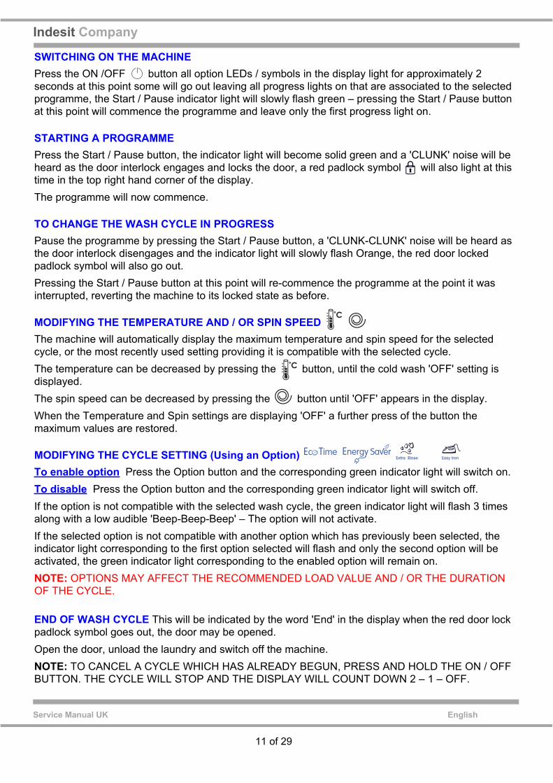
MODIFYING THE TEMPERATURE AND / OR SPIN SPEED The machine will automatically display the maximum temperature and spin speed for the selected cycle, or the most recently used setting providing it is compatible with the selected cycle.The temperature can be decreased by pressing the button, until the cold wash 'OFF' setting is displayed.The spin speed can be decreased by pressing the button until 'OFF' appears in the display.When the Temperature and Spin settings are displaying 'OFF' a further press of the button the maximum values are restored.
MODIFYING THE CYCLE SETTING (Using an Option) To enable option Press the Option button and the corresponding green indicator light will switch on.To disable Press the Option button and the corresponding green indicator light will switch off.If the option is not compatible with the selected wash cycle, the green indicator light will flash 3 times along with a low audible 'Beep-Beep-Beep' – The option will not activate.If the selected option is not compatible with another option which has previously been selected, the indicator light corresponding to the first option selected will flash and only the second option will be activated, the green indicator light corresponding to the enabled option will remain on.NOTE: OPTIONS MAY AFFECT THE RECOMMENDED LOAD VALUE AND / OR THE DURATION OF THE CYCLE.
END OF WASH CYCLE This will be indicated by the word 'End' in the display when the red door lock padlock symbol goes out, the door may be opened.Open the door, unload the laundry and switch off the machine.NOTE: TO CANCEL A CYCLE WHICH HAS ALREADY BEGUN, PRESS AND HOLD THE ON / OFF BUTTON. THE CYCLE WILL STOP AND THE DISPLAY WILL COUNT DOWN 2 – 1 – OFF.

12 of 29
Service Manual UK
Indesit Company
English
Special Wash Cycles
Outwear (programme 9): Is ideal for washing water-repellent fabrics and winter jackets (e.g.Gore-Tex, polyester, nylon); for best results, use a liquid detergent and dosage suitable for a half-load; pre-treat necks, cuffs and stains if necessary; do not use softeners or detergents containing softeners. Stuffed duvets cannot be washed with this programme.
Wool (programme 10): All wool garments can be washed using programme 10, even those carrying the “hand-wash only” label. For best results, use special detergents and do not exceed 2 kg of laundry.
Jeans (programme 11): Turn garments inside-out before washing and use a liquid detergent.
Sport Intensive (programme 12): is for washing heavily soiled sports clothing fabrics (tracksuits, shorts, etc.); for best results, we recommend not exceeding the maximum load indicated in the “Programme table”.
Sport Light (programme 13): is for washing lightly soiled sports clothing fabrics (tracksuits, shorts, etc.); for best results, we recommend not exceeding the maximum load indicated in the “Programme table”. We recommend using a liquid detergent and dosage suitable for a half-load.
Special Shoes (programme 14): is for washing sports shoes; for best results, do not wash more than 2 pairs simultaneously.
The 20° wash cycles (Zone 20°) offer effective washing performance at low temperatures, reducing electricity usage and expenditure while benefiting the environment. The 20° wash cycles meet all requirements:
Cotton Standard (programme 6) ideal for heavily soiled cotton loads. The effective performance levels achieved at cold temperatures, which are comparable to washing at 40°, are guaranteed by a mechanical action which operates at varying speed, with repeated and frequent peaks.
Mix Light (programme 7): ideal for mixed loads (cotton and synthetics) with a normal soil level.The effective performance levels achieved at cold temperatures are guaranteed by a mechanical action which operates at varying speed, across set average intervals.
20' Refresh (programme 8): ideal for refreshing and washing lightly soiled garments in a few minutes. It lasts just 20 minutes and therefore saves both time and energy. It can be used to wash different types of fabrics together (except for wool and silk), with a maximum load of 1.5 kg.
13 of 29
Indesit Company
Service Manual UK English
Autotest Sequence(Test duration 8-10 minutes)
To start Autotest:Turn Programme selector knob to the 12 o’clock position (programme 1) and turn Temperature selector to 30°C and follow the instructions below:Switch on the machine and turn the programme selector clockwise one position (programme 2).Switch off the machine and return the programme selector to the 12 o’clock position.Switch on the machine and turn the programme selector clockwise two positions (programme 3).Switch off the machine and return the programme selector to the 12 o’clock position.Switch on the machine and turn the programme selector anti clockwise one position (drain programme)
Press Start button to commence Autotest.
Sequence Actions:1. Machine fills with approximately 1 Litre of water through Pre-wash valve.2 Machine fills with approximately 1 Litre of water through Main wash valve.3. Machine fills through both valves - filling through all compartments for approximately
30 seconds until full pressure switch level is achieved.4. Main motor operates - drum agitation Clockwise and Anticlockwise.5. Wash heater activates until water temperature reaches 30°C approximately 4 minutes duration.
(Variable temperature knob must be set above 30°C to achieve the heater test, if correct position is not selected the autotest will continue through without checking temperature increase).
6. Drain pump operates, spin commences approximately 4 minutes duration.7. Test Complete.
LOADING DETERGENT
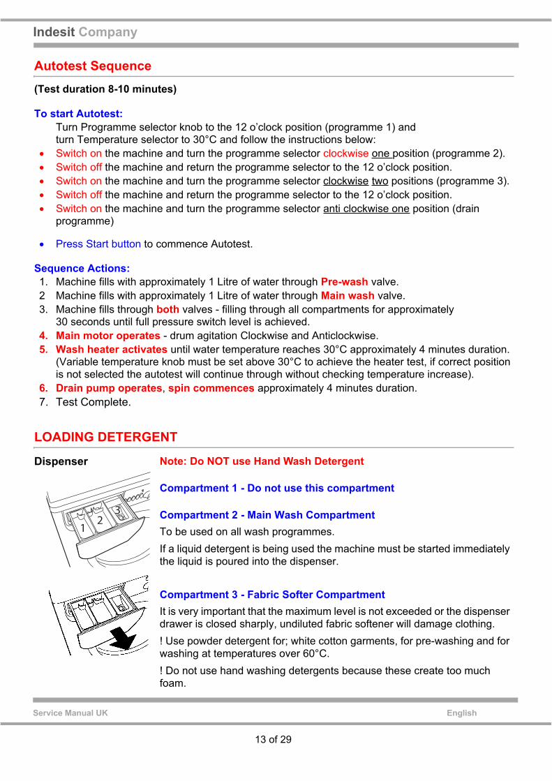
Dispenser Note: Do NOT use Hand Wash Detergent
Compartment 1 - Do not use this compartment
Compartment 2 - Main Wash CompartmentTo be used on all wash programmes.If a liquid detergent is being used the machine must be started immediately the liquid is poured into the dispenser.
Compartment 3 - Fabric Softer Compartment It is very important that the maximum level is not exceeded or the dispenser drawer is closed sharply, undiluted fabric softener will damage clothing.! Use powder detergent for; white cotton garments, for pre-washing and for washing at temperatures over 60°C.! Do not use hand washing detergents because these create too much foam.
12
3

14 of 29
Service Manual UK
Indesit Company
English
WASH CYCLES & PROGRAMMES

15 of 29
Indesit Company
Service Manual UK English
NEW COMPONENTS
Control ModuleThe Programme Selector, Temperature Selector and LEDs are now all part of the Display Module and are not individually interchangeable. This module communicates with the Power Module at the rear of the machine. These machines DO NOT have an EEPROM on the Display module.The EEPROM is fitted on the power module - see below.
Power Module and SmartCardThe production module has an EEPROM which is soldered in place and is not replaceable. Power Modules supplied as Spare Parts also have a soldered (welded) EEPROM, therefore the relevant SmartCard for the model and Module must be ordered if either part is required. Indesit Company engineers can rewrite the module using the relevant file from their E-Mit unit.
Anti FoamingWhen spinning, if the pressure switch switches to the full position due to foam in the drum, the machine will go into an Anti Foam cycle. This is most likely to occur the first time the machine spins after the wash cycle.
Anti Foam Cycle:1. Pause for 2 minutes2. Fill 10 litres from the main wash valve3. Slow drum action 5" on, 25" off for 2 minutes4. Spinning restarts.
This process is repeated until all the foam has been pumped away.

16 of 29
Service Manual UK
Indesit Company
English
PROGRAMMING (Using EMIT)
This machine can be programmed via the Emit, using a USB lead (Part number C00222800), Hardware key (Part number C00115587) and the Memwriter software.
The Black Hardware Key and USB Serial Cable will be replaced with a new style Hardware Key and Cable which now has full USB connections. It has shorter, more robust pins, similar to those currently fitted into the SmartCard Reader.NOTE: - The USB Hardware Key also supports a low voltage connection point which allows an external power supply to be connected to the Hardware Key which enables the main module to be programmed with a settings file prior to fitting it to an appliance. ** NOT applicable to UK Service Engineers.
USB Hardware Key - C00289048
Black Hardware Key USB - Serial Cable
Replacement pins for the Hardware Key are available as Part No. C00114723 (Qty = 1)
Other types of Cable are available
Low VoltageConnection Point
USB Connection
USB CableC00289046
17 of 29
Indesit Company
Service Manual UK English
MAIN BOARD PROGRAMMING - For Modules with fixed EEProm
PROGRAMMING (Using Smartcard Reader / Card)
If the Main Module has been replaced during a repair the board will require programming using the fol-lowing method.
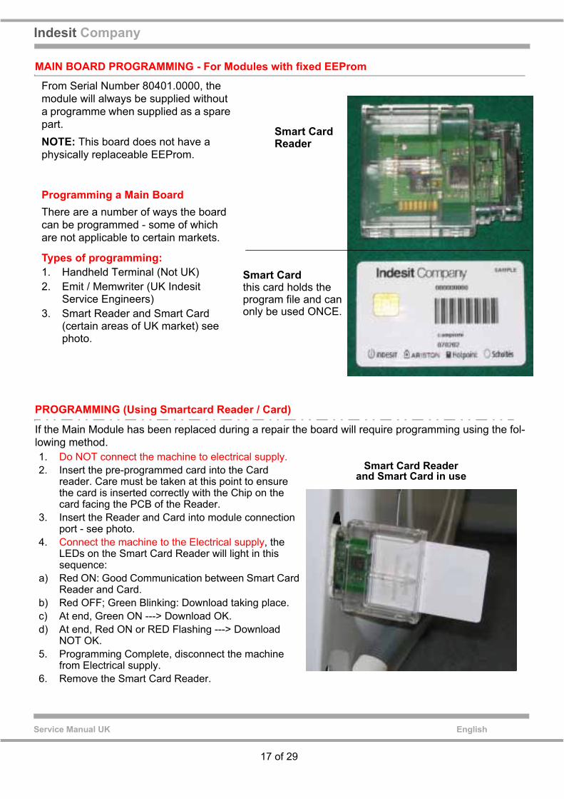
From Serial Number 80401.0000, the module will always be supplied without a programme when supplied as a spare part.NOTE: This board does not have a physically replaceable EEProm.
Programming a Main BoardThere are a number of ways the board can be programmed - some of which are not applicable to certain markets.
Types of programming:1. Handheld Terminal (Not UK)2. Emit / Memwriter (UK Indesit
Service Engineers)3. Smart Reader and Smart Card
(certain areas of UK market) see photo.
1. Do NOT connect the machine to electrical supply.2. Insert the pre-programmed card into the Card
reader. Care must be taken at this point to ensure the card is inserted correctly with the Chip on the card facing the PCB of the Reader.
3. Insert the Reader and Card into module connection port - see photo.
4. Connect the machine to the Electrical supply, the LEDs on the Smart Card Reader will light in this sequence:
a) Red ON: Good Communication between Smart Card Reader and Card.
b) Red OFF; Green Blinking: Download taking place.c) At end, Green ON ---> Download OK.d) At end, Red ON or RED Flashing ---> Download
NOT OK.5. Programming Complete, disconnect the machine
from Electrical supply.6. Remove the Smart Card Reader.
Smart Card Reader and Smart Card in use
Smart Card
Smart Cardthis card holds the program file and can only be used ONCE.
Reader

IndesitCom
pany
18 of 29
Service Manual U
KEnglish
WIRING DIAGRAM
1
2
321
4 6 7
1
3
1
3
L N
P L
9
TF
3 4 52
1
3
1
J9 J9JE8JE11
J10
J10
JE13J11JE15
3 ????
5 4 3
2
+5V
5 34 1
GN
D
P
JE71 3 44 5
JE14
1
2
220 - 240 Vac
12V
D
Gnd
SC
L
SD
A JE12
LC N
2 2112345
124689131 2 3 42 1345 1234
1
2
3
4
5
???
3 4
1
Lin
ea
Neu
tro
Q7Triac
Triacopzionale
Q6Triac
Q2Triac
Q3Triac
Q4Triac
Q5Triac
R4
5
6 7
K?Deviat
K?Resist
4 3
1
K?Res. Asc.
Wash Heaterwiththermal fuse
Test
Co
nn
ecto
r
Pump
LinearPressureSwitchWash
NTCPre-Wash Wash
Motor(3 phase)
Tacho
Water valves
Brown
Brown
DISPLAY / CONTROLDoor Lock
Mains Filter
BrownBrown
RedRed
Red
Neutral Neutral
Neutral
Live
Live
RedRed
Lig
ht
Blu
e
Bla
ck
Bla
ck
Wh
ite
Wh
ite Li
gh
t B
lue
Sig
nal
Lig
ht
Blu
e
Bla
ck
Bla
ck Bla
ck
Lig
ht
Blu
e
Lig
ht
Blu
e
Blue
Blue
E
5407770wd.pdf

19 of 29
Indesit Company
Service Manual UK English
WIRING CONNECTIONS (ARDACIA 2 PLATFORM)
RED 0.35 X 1550RED 0.35 X 1550RED 0.35 X 1550RED 0.35 X 1550
DISPLAY
RED 0.35 X 1550
PRESSURE SWITCH
BROWN 1.00 X 1700
DOOR LOCK / PUMP
EARTH
J10
MRCMRLMRN -1-
-2-
-3-
-1-
-2-
PS
1J10
1JE7
MOTOR
MOTOR
JE7-7-
-6-
-5-
-4-
-3-
-2-
-1-
BLACK 0.75 X 730BLACK 0.75 X 730
RED 0.50 X 730
RED 0.50 X 730
BLACK 0.75 X 730
MAINS FILTER
J9
FA2FA1
R.TF.R.R.
L/N
BLUE 1.00 X 530BROWN 1.00 X 530BLUE 1.00 X 900BROWN 1.00 X 900
4J9
-2--1-
GREEN/YELLOW 1.0 X 1220TG TR
LIGHT BLUE 0.35 X 570LIGHT BLUE 0.35 X 570
VALVES / NTC THERMISTOR
EVL
EVP
WASH NTC
WHITE 0.35 X 1520
WHITE 0.35 X 1520
LIGHT BLUE 0.35 X 1520
LIGHT BLUE 0.35 X 1520
1
3
1
3
1
3
2
4
1
6
7
9
JE11
JE15
BROWN 1.00 X 1700RED 0.50 X 1700RED 0.50 X 600RED 0.50 X 600
Display
3J92J91J9
2J103J104J105J10
2JE73JE74JE75JE7
32
45
1
32
45
1
MODULE
MODULE MODULE
MODULE
PREWASH
MAIN
MODULE
DOORLOCK
PUMP
celeste 0.35 X 1340celeste 0.35 X 1340
JE8
celeste 0.35 X 1340
32
45
1
1
32

20 of 29
Service Manual UK
Indesit Company
English
POWER MODULE CONNECTIONS
10
1
J13
??
143
2
WAVE
D45
C93
RV5
RV3
RV2
RV1
RV4
R253
R205
C79
???
C10
C4
C77
C81
???
C85C9
2
C61
JP4
1
D51
D50
D47
D44
D46
D36
C35
D31
IS01
IS02
IS03
IS04
Q49
Q27
Q29
Q32
K3
K1K2
1
J6
FTICT
IDD02
09.2
JE7
JE12
JE11
JE8
JE15
JE14
Q10
Q12
???
Q9
Q11 Q8
Y1
J1J2
J3
J5J4
C80
RT3
RT2
C28
D8
C29
D29
J10
T1
C82
U12 U13
U9
R206
J9
C95
11
1
1 1 1
JE7
JE11
J10
J9
JE15 JE8
AUTO TESTSOCKET
21 of 29
Indesit Company
Service Manual UK English
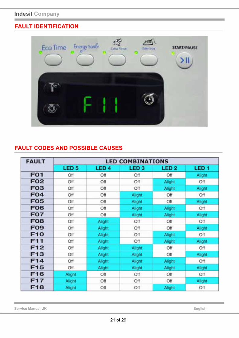
FAULT IDENTIFICATION
FAULT CODES AND POSSIBLE CAUSES

22 of 29
Service Manual UK
Indesit Company
English
FAULT FINDINGIMPORTANT NOTE: Disconnect the machine from Electricity Supply before any testing.
General Information
If the machine has an Earth Fault it can display erroneous fault codes. Repair any Earth Faults on the machine before using the code guide on the previous page.
Some faults will not show up as error codes:-The module will not show up a fault if the water to the machine is turned off or if the solenoid valves are open circuit.Certain motor faults, will not show as a fault, the door will lock but the machine will not start a programme. (motor plug disconnected, faulty brushes etc.)Open circuit field windings will signal fault F01.If the motor Thermoprotector (toc) - if fitted -operates in the middle of a cycle, the machine will stop with no fault code indicated, when the thermoprotector (toc) resets the cycle will then restart.If the element goes open circuit in the middle of a programme and the pressure switch is in the full position, the machine may not signal a fault but will wash for a long extended period.
Note: This chart refers to both "commutator" (brush motor) and "three phase" (non-brush motor) models. Refer to text for appropriate information.
FAULT CAUSE SERVICE ACTIONS
F01 Main PCB, Triac on board damaged or componentsFeedback fault
- Check for water leaks that may affect connectors J009 (Commutator) or J9 (Three-phase) causing the relative contacts to short;- Check the motor terminal board (any problems due to aggression caused by manufacturing chemical residues that may cause short circuits);- Check the connection on the wash heating element;- Check efficiency of connector J001 (Commutator) or J010 (Three-phase) on the PCB;- Check connector J001 (Commutator) or J10 (Three-phase) pins 3 and 4 for continuity of the wash heating element (1700 watt - 230 volt) which must be 30 Ohm +/- 10%. Otherwise, renew heating element;- Check for water leaks that may affect connectors J006 (Commutator) or J7 (Three-phase) causing the relative contacts to short;- Check the terminal board (any problems due to aggression caused by manufacturing chemical residues that may cause short circuits);- Check wiring of connectors J006 (Commutator) or J7 (three phase) / Pressure switch;- Disconnect appliance for 2 minutes. Check wiring and connectors of the dryer heating element on main PCB board side and component side;- Check that correct operation has been restored by starting the Autotest routine;- Renew main PCB.

23 of 29
Indesit Company
Service Manual UK English
F02 Motor tripped, motor tacho generator open circuit or short circuit
- Check for water leaks that may affect connector J009 causing the contacts to short circuit;- Check to ensure motor is not mechanically jammed or seized;- Check efficiency of the contacts on connector J009 on the PCB;- Check the motor side connector;- Check motor winding and check that the impedance value on wiring connector J009 between pins 3 and 4, 4 and 5, 3 and 5 is less than 100 Ohm; (three phase)- Check the tacho generator winding and check that the impedance value on wiring connector J009 between pins 1 and 2 is between 115 and 170 Ohm;- Check the tacho generator wiring;- Disconnect appliance for 2 minutes. Check that correct operation has been restored by starting the Autotest routine;- Renew motor;- Renew PCB.
F03 NTC wash sensor open ! short circuit
- Check efficiency of contacts on connector J005 (commutator) or J12 (three-phase) on PCB;- Check NTC ensuring that the impedance value at ambient temperature (20°C) on wiring connector J005 (commutator) or J12 (three-phase) pins 1 and 2 is approximately 20 KOhm- If measurement is incorrect check continuity of wiring J005 (commutator) or J12 (three phase), pins 1 and 2 / NTC;- Check the same parameter directly on the NTC (20 KOhm);- Renew NTC;- Renew PCB.
F05 Pressure switch empty condition not reached or drain pump jammed
- If status type pressure switch check correct operation of component;- Check efficiency of contacts of connector J006 (commutator) or J7 (three phase) on PCB;- Check wiring of connectors J006 (Commutator) or J7 (three phase) / Pressure switch;- Check continuity of pump on connectors J004 (commutator) or J11 (three-phase), pins 4 and 5 (in case of classic door lock); check that impedance value is 170 Ohm +1- 10%;- Check wiring of connectors J004 (commutator) or J11 (three- phase), pins 4 and 5 / pump;- Check pump filter + and wall drain outlet;- Renew drain pump;- Empty tank, reprogram Main PCB then start autotest routine;- Renew linear pressure switch;- Renew PCB.

24 of 29
Service Manual UK
Indesit Company
English
F06 Door lock fails to close / open, door lock PTC triac open / closed, mains frequency signal fault, mains power signal fault
- Check for water leaks that may affect connectors J004 or J11 (three-phase) causing the relative contacts to short;- Check Door lock terminal board (any problems due to aggression caused by manufacturing chemical residues that may cause short circuits);- Check J004 / door lock wiring;- Check door lock;- Renew PCB.
F07 Wash heating element relay open / diverter relay sticking on drain pump side
- Check efficiency of contacts on connector J001 (commutator) or J10 (three-phase) on PCB;- Check continuity of wash heating element on connectorsJ001 (Commutator) or J10 (Three-phase), pins 3 and 4.The 1700W 230V heating element impedance value is 30 Ohm +/- 10%. If value is different renew wash heating element;- Renew PCB.
F08 Wash heating element relay earth leakage / wash heating element relay contacts sticking
- Check efficiency of contacts on connector J001 (commutator) or J10 (three-phase) on PCB;- Check leakage between the two ends and ground, impedance should be at least 2 MOhm;- Renew heating element;- Renew PCB.
F09 Setting File error detected by Main PCB or Display PCB
- Disconnect appliance for 2 minutes. Check that correct operation has been restored by starting the Autotest routine;- Reprogram Main PCB;- Renew main PCB;- Renew display PCB.
F11 Pump not wired or pump driving triac short circuit
- Check efficiency of contacts on connector J004 (commutator) or J11 (three-phase) on PCB;- Check continuity on connector J004 (commutator) or J11 (three- phase), pins 4 and 5 (in the case of classic door lock);- Check continuity of pump, ensuring that impedance value is 170 Ohm +/- 10%;- Check wiring of connector J004 (commutator) or J11 (three phase) / pump;- Renew pump;- Renew PCB.
F12 Communicationerror between Main PCB and Display PCB
- Check efficiency of contacts on connector J010 (Commutator) or J16 (Three-phase) on main PCB;- Check efficiency of contacts on Display PCB;- Check continuity of J010 (Commutator) or J16 (Three-phase)/ Display PCB wiring;- Disconnect appliance, wait for 2 minutes and reconnect to power supply, then start autotest routine;If problem persists proceed as follows:- Renew main PCB;- Renew display PCB.

25 of 29
Indesit Company
Service Manual UK English
F13 NTC dryer sensor open I short circuit
- Check efficiency of contacts on connector J011 (commutator) or J14 (three-phase) on PCB;- Check NTC impedance value on wiring connectors J011 (commutator) or J14 (three-phase) between pin 1 and pin 2.The impedance value at ambient temperature (20°C) must be approximately 20 KOhm;- If measurement is incorrect check NTC wiring;- Check the same parameter directly on the NTC (20 KOhm);- Renew NTC;- Renew PCB.
F15 Dryer heating element ground fault/short circuit. Board relay sticking
- Check efficiency of contacts on connector J012 (commutator) or J13 (three-phase) on PCB;- Check continuity of the dryer heating element on pins 1 and 2 of connector J012 (commutator) or J13 (three-phase) ensuring that the value for the 1500W 230V heating element is approximately 36 Ohm;- Check leakage between the two ends and ground, impedance should be at least 2 MOhm;- Renew dryer heating element;- Renew PCB.
F18 (Three phase Models Only)No communication betweenmicroprocessor on the main module and the DSP (componentdriving the Three Phase motor)
- Disconnect appliance for 2 minutes. Check that correct operation has been restored by starting the Autotest routine;If fault reappears renew main PCB.

26 of 29
Service Manual UK
Indesit Company
English
DISMANTLING INSTRUCTIONS - Arcadia Models
Safety Notes:Ensure that the appliance is disconnected form the Electricity Supply before commencing any work. Beware of sharp edges on metal or plastic parts - wear safety gloves. Refer to Safety Notes at the beginning of this publication.!
A Top Cover1. Remove the 2 screws securing the top panel.2. Slide forward and lift clear.
B Back Panel1. Remove 6 screws securing panel.2. Slide down to remove.
C Control Panel1. Remove the top cover (A).2 Open the dispenser drawer fully. Gently lift slightly and pull to remove the drawer.
Remove the screws securing control panel to dispenser housing.3. Release 2 screws, 1 each end on top corner of control panel.4. Release 2 clips holding console to cabinet, gently ease control panel upwards to disengage lugs from
the front panel.5. Disconnect the wiring and lift clear.
Note: When refitting, ensure the control panel is screwed and secured into the dispenser body.This is easier to check with the dispenser drawer removed.
D Display Card1. Remove the top cover (A).2. Release the wiring block from the back of the card.3. Remove screws fixing the PCB to the control panel.4. Whilst holding the card, ease card away from the control panel.
E Top Concrete Weight1. Remove the top cover (A).2. Remove the 3 fixing bolts and lift clear.
IMPORTANT NOTERisk of Electric ShockThe metal heatsink fitted on the Power Module may hold an electrical charge for a short period after switching off the machine.Allow 5 minutes after disconnecting the machine from the electrical supply before commencing ANY work.

27 of 29
Indesit Company
Service Manual UK English
F Dispenser/Valve Assembly1. Remove the top cover (A).2. Remove the drawer.3. Remove the screws securing the dispenser to the control panel.4. Remove the inlet valve fixing screws to the rear of the cabinet.5. Remove the control panel (C).6. Unhook the dispenser outlet hose from the dispenser.7. Remove the wires, lift clear and remove the dispenser valve assembly.
G Fill Valves1. Remove the top cover (A).2. Remove the inlet valve fixing screws to the rear of the cabinet.3. Remove the control panel (C) and ease the dispenser assembly forward.4. Remove the screws securing the valve to the dispenser.5. Disconnect the wiring.
H Door Seal1. Remove the top cover (A).2. Remove the outer wire clamp, attaching the door seal to the cabinet (R).3. Release the door seal from the cabinet front.4. Remove the door seal from the tank front. The seal is fixed to the tank front by a sprung band.
I Door Interlock1. Remove the restrainer securing the door seal to the front panel (R).2. Remove the two securing screws and working from the drum aperture behind the door seal disconnect
the wiring.
J Belt and Pulley Removal1. Remove the back panel (B) to gain access to the belt.2. Using pulley locking tool, Part No. C00560114 (560114), remove the pulley fixing screw and ease pulley
away from the shaft.
K Mains Suppressor1. Remove the top cover (A).2. Remove the screw securing the suppressor and mains cable unit to the cabinet.3. Lift unit upwards and withdraw from cabinet. Note: This unit is not a customer fit part.
L Drum Assembly1. Remove the Top Cover (A), Back Panel (B), Control Panel (C), Dispenser (F) and Motor (N).2. Remove the screws securing pump to front panel.3. Disconnect the wiring attached to the outer drum via cable clips and any earth wires.4. Disconnect the tube from the pressure switch.5. Unclip the dispenser outlet hose from the dispenser and remove door seal from front panel.6. Insert slide Part No. C00222704 (5600155), inside the cabinet at the rear of the drum.7. Using suitable protection lay appliance on its back.8. Remove 2 x 10 mm nuts securing the shock absorbers to the base of the cabinet.9. Remove the tank/pump hose.10. Carefully slide the outer drum clear, protecting any wiring.

28 of 29
Service Manual UK
Indesit Company
English
M Front Concrete Weight1. Remove the drum assembly (L).2. Remove the 3 weight fixing bolts and lift clear.
N Motor1. Remove the back panel (B).2. Remove the bolts securing the motor and support the motor.3. Pull the motor forward of the locating pegs and lift clear.
O Pump1. Remove the plinth.2. Using suitable protection, tilt the machine backwards and support.3. Remove the pump fixing screws and disconnect the hoses and wiring.
P Power Module1. Remove the back panel (B).2. Remove 2 screws securing the module support to the cabinet.3. Disconnect the wiring.4. Lift module and support clear.
Q BearingsNote: The drum bearing assembly comes as a complete unit, therefore the bearings cannot be replaced. A new drum/tank assembly will need to be fitted if the bearings have failed.
R Door Seal Retainer to Outer Case1. The door seal is fixed to the cabinet front panel by a wire clamp and a small spring. The spring is usually
at the bottom of the door.2. Carefully attach a small screwdriver to one of the ears of the spring. By stretching the spring the wire
band can be removed.
S Shock Absorbers1. Using suitable protection lean the appliance onto one
side.2. Remove the 10 mm nut securing the shock absorber to
the cabinet.3. Push the shock absorber on the rod until it comes out of
the cabinet.4. Remove the plastic expansion rivet fixing the shock
absorber to the tank. (Remove the pin first to make removal easier.)

29 of 29
Indesit Company
Service Manual UK English