Self-operated Pressure Regulators PN 16 to PN 40 · …samson-automation.info/pdf/t25000en.pdf ·...
14
Self-operated Pressure Regulators PN 16 to PN 40 · Class 125 to 300 DN 15 to DN 400 · NPS ½ to 10 · G 3 8 to G 1 · –10 °C to 350 °C · 15 to 660 °F Edition June 2006 Information Sheet T 2500 EN
Transcript of Self-operated Pressure Regulators PN 16 to PN 40 · …samson-automation.info/pdf/t25000en.pdf ·...
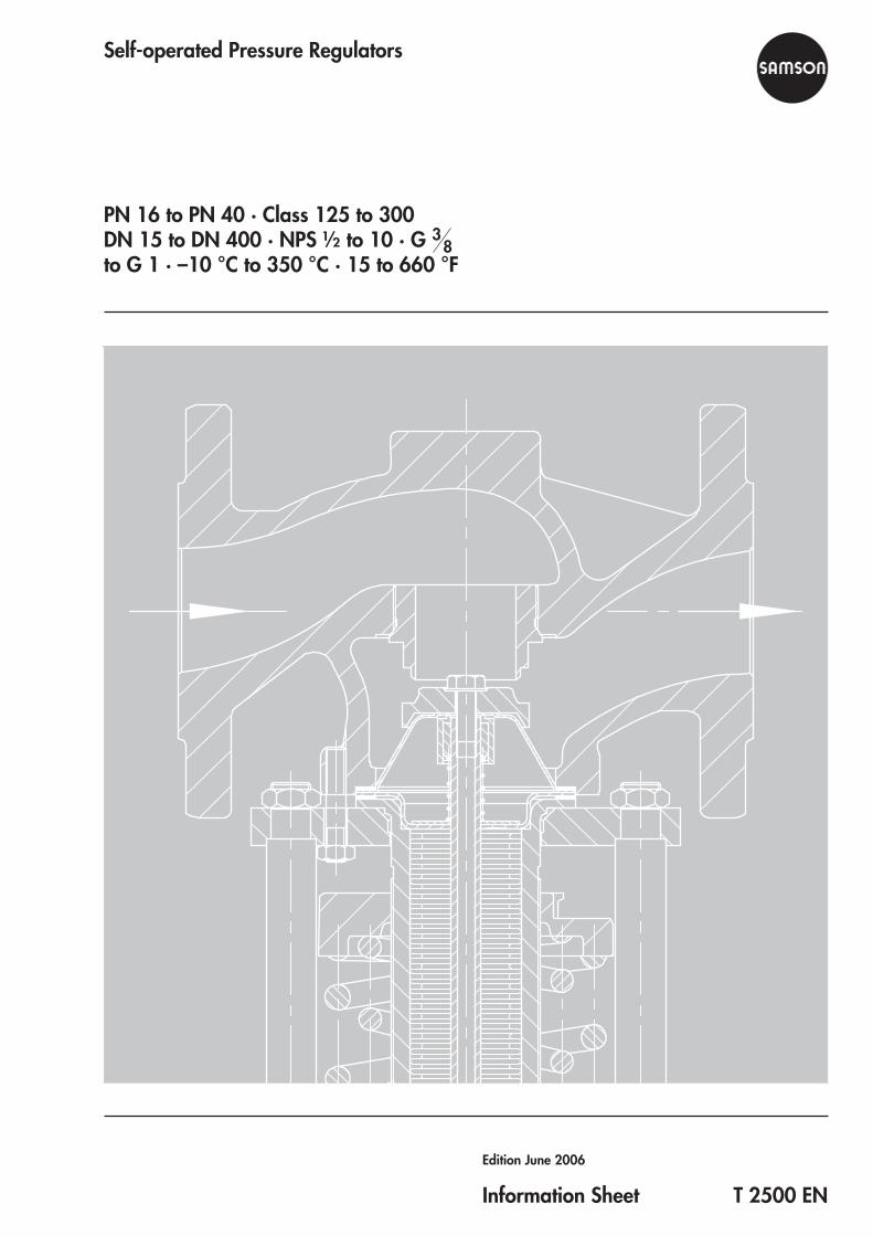
Self-operated Pressure Regulators
PN 16 to PN 40 · Class 125 to 300DN 15 to DN 400 · NPS ½ to 10 · G 3
8to G 1 · –10 °C to 350 °C · 15 to 660 °F
Edition June 2006
Information Sheet T 2500 EN
2 T 2500 EN
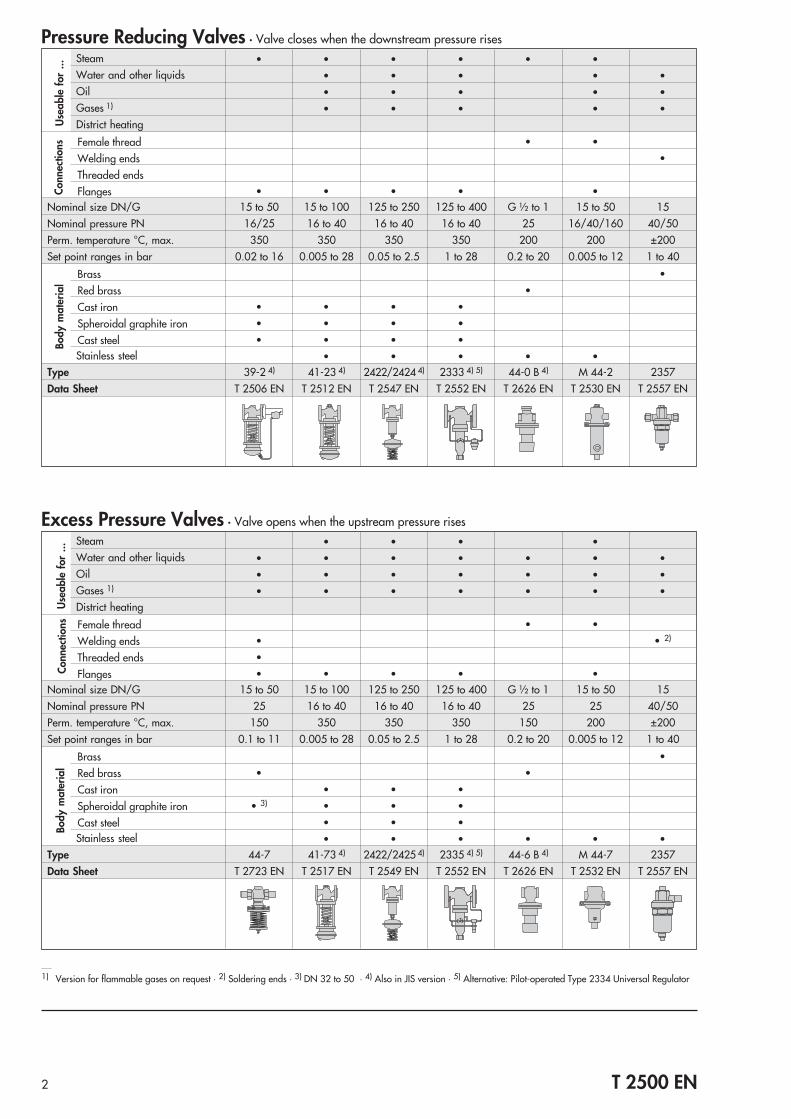
Pressure Reducing Valves · Valve closes when the downstream pressure risesSteam • • • • • •Water and other liquids • • • • •Oil • • • • •Gases 1) • • • • •District heating
Female thread • •
Welding ends •
Threaded endsFlanges • • • • •
Nominal size DN/G 15 to 50 15 to 100 125 to 250 125 to 400 G ½ to 1 15 to 50 15Nominal pressure PN 16/25 16 to 40 16 to 40 16 to 40 25 16/40/160 40/50Perm. temperature °C, max. 350 350 350 350 200 200 ±200Set point ranges in bar 0.02 to 16 0.005 to 28 0.05 to 2.5 1 to 28 0.2 to 20 0.005 to 12 1 to 40
Brass •
Red brass •
Cast iron • • • •
Spheroidal graphite iron • • • •
Cast steel • • • •Stainless steel • • • • •
Type 39-2 4) 41-23 4) 2422/2424 4) 2333 4) 5) 44-0 B 4) M 44-2 2357Data Sheet T 2506 EN T 2512 EN T 2547 EN T 2552 EN T 2626 EN T 2530 EN T 2557 EN
Use
able
for
...Bo
dym
ater
ial
Excess Pressure Valves · Valve opens when the upstream pressure risesSteam • • • •Water and other liquids • • • • • • •Oil • • • • • • •Gases 1) • • • • • • •District heating
Female thread • •
Welding ends • • 2)
Threaded ends •
Flanges • • • • •Nominal size DN/G 15 to 50 15 to 100 125 to 250 125 to 400 G ½ to 1 15 to 50 15Nominal pressure PN 25 16 to 40 16 to 40 16 to 40 25 25 40/50Perm. temperature °C, max. 150 350 350 350 150 200 ±200Set point ranges in bar 0.1 to 11 0.005 to 28 0.05 to 2.5 1 to 28 0.2 to 20 0.005 to 12 1 to 40
Brass •
Red brass • •
Cast iron • • •
Spheroidal graphite iron • 3) • • •
Cast steel • • •Stainless steel • • • • • •
Type 44-7 41-73 4) 2422/2425 4) 2335 4) 5) 44-6 B 4) M 44-7 2357Data Sheet T 2723 EN T 2517 EN T 2549 EN T 2552 EN T 2626 EN T 2532 EN T 2557 EN
Use
able
for
...Bo
dym
ater
ial
1) Version for flammable gases on request · 2) Soldering ends · 3) DN 32 to 50 · 4) Also in JIS version · 5) Alternative: Pilot-operated Type 2334 Universal Regulator
Conn
ectio
nsCo
nnec
tions
3 T 2500 EN
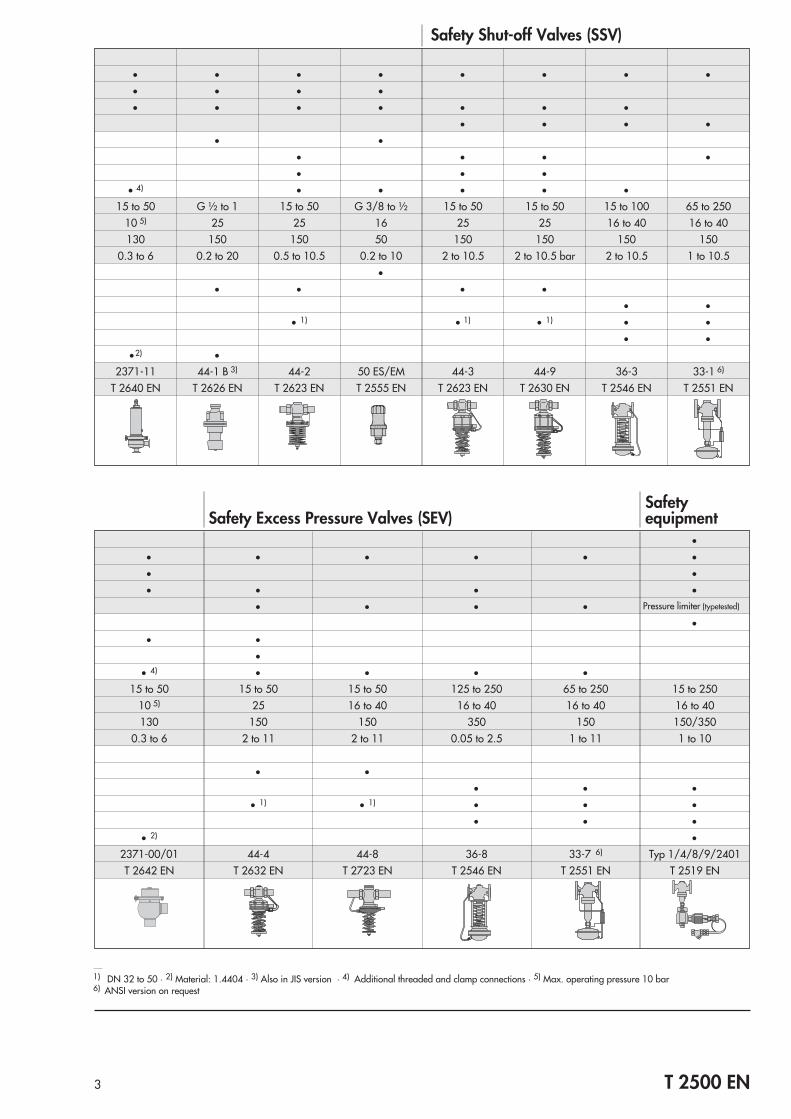
Safety Shut-off Valves (SSV)
• • • • • • • •• • • •• • • • • • •
• • • •• •
• • • •• • •
• 4) • • • • •15 to 50 G ½ to 1 15 to 50 G 3/8 to ½ 15 to 50 15 to 50 15 to 100 65 to 250
10 5) 25 25 16 25 25 16 to 40 16 to 40130 150 150 50 150 150 150 150
0.3 to 6 0.2 to 20 0.5 to 10.5 0.2 to 10 2 to 10.5 2 to 10.5 bar 2 to 10.5 1 to 10.5•
• • • •• •
• 1) • 1) • 1) • •• •
•2) •2371-11 44-1 B 3) 44-2 50 ES/EM 44-3 44-9 36-3 33-1 6)
T 2640 EN T 2626 EN T 2623 EN T 2555 EN T 2623 EN T 2630 EN T 2546 EN T 2551 EN
•• • • • • •• •• • • •
• • • • Pressure limiter (typetested)
•• •
•• 4) • • • •
15 to 50 15 to 50 15 to 50 125 to 250 65 to 250 15 to 25010 5) 25 16 to 40 16 to 40 16 to 40 16 to 40130 150 150 350 150 150/350
0.3 to 6 2 to 11 2 to 11 0.05 to 2.5 1 to 11 1 to 10
• •• • •
• 1) • 1) • • •• • •
• 2) •2371-00/01 44-4 44-8 36-8 33-7 6) Typ 1/4/8/9/2401T 2642 EN T 2632 EN T 2723 EN T 2546 EN T 2551 EN T 2519 EN
Safetyequipment
1) DN 32 to 50 · 2) Material: 1.4404 · 3) Also in JIS version · 4) Additional threaded and clamp connections · 5) Max. operating pressure 10 bar6) ANSI version on request
Safety Excess Pressure Valves (SEV)

4 T 2500 EN
Pressure Reducing Valves · Valve closes when the downstream pressure rises
Steam • • • • •Water and otherliquids • • • • •
Oil • • • • •Gases 1) • • • • •District heating
Female thread • •
Welding endsThreaded endsFlanges • • • • • 5)
Nominal size NPS ½ to 2 ½ to 4 6 to 10 6 to 10 ½ to 1 NPT ½ to 1 NPT ½ to 2Pressure rating/ANSI Class 125 to 300 125 to 300 125 to 300 125 to 300 250 250 150 4)
Perm. temperature °F, max. 660 660 660 660 390 300 266Set point ranges in psi 0.2 to 16 0.075 to 230 0.75 to 35 14.5 to 400 3 to 290 3 to 290 5 to 90
Red brass (C83600) • •
Cast iron (A126B) • • •
Carbon steel (A216 WCC) • • • •Stainless steel (A351CF8M) • • • • • • 3)
Type 39-2 41-23 2422/2424 2333 2) 44-0 B 44-1 B 2371-11Data Sheet T 2508 EN T 2513 EN T 2548 EN T 2554 EN T 2627 EN T 2627 EN T 2640 EN
ANSI versionsU
seab
lefo
r...
Body
mat
eria
l
Excess Pressure Valves · Valve opens when the upstream pressure rises
Steam • • •Water and otherliquids • • • • •
Oil • • • • •Gases 1) • • • • •District heating
Female thread •
Welding ends • 5)
Threaded endsFlanges • • • • 5)
Nominal size NPT ½ to 4 6 to 10 6 to 10 ½ to 1 NPT ½ to 2Pressure rating/ANSI Class 125 to 300 125 to 300 125 to 300 250 150 4)
Perm. temperature °F, max. 660 660 660 390 266Set point ranges in psi 0.075 to 230 0.75 to 35 14.5 to 400 3 to 290 5 to 90
Red brass (C83600) •
Cast iron (A126B) • • •
Carbon steel (A216 WCC) • • •Stainless steel (A351CF8M) • • • • • 3)
Type 41-73 2422/2425 2335 2) 44-6 B 2371-00/01Data Sheet T 2518 EN T 2550 EN T 2554 EN T 2627 EN T 2642 EN
Use
able
for
...Bo
dym
ater
ial
1) Version for flammable gases on request · 2) Alternative: Pilot-operated Type 2334 Regulator · 3) Material: 316L · 4) Max. operating pressure 150 psi5) Additional threaded and clamp connections
Conn
ectio
nsCo
nnec
tions

Principle of operationSelf-operated pressure regulators are control devices whosemeasuring units draw their energy from the process mediumwhich creates sufficient force to move the final control element.The regulators consist of a valve and an actuator which eitheropens or closes the valve when the pressure increases. Theregulators are proportional regulators controlled by the processmedium. Each deviation from the adjusted set point is assigneda certain valve plug position.
Pressure reducing valvesPressure reducing valves or pressure reducing stationswithdraw as much energy from a pressure vessel with a higherpressure level as needed to maintain a nearly constant pressurelevel in downstream equipment, although consumptionfluctuates.The pressure p2 to be controlled (controlled variable x)produces the force Fm = p2 x A, which is proportional to thecontrolled variable, on the diaphragm area A. This forcecorresponds to the actual value and is compared at the plugstem with the spring force FS= set pointw. FS is adjustable at theset point adjuster. If the pressure p2 changes, and in this wayalso the force Fm, the valve plug is being adjusted until Fm = FS.In the version shown in Fig. 1.1, the valve closes when thepressure to be maintained constant rises. The regulator, in thiscase a pressure reducing valve, adjusts the pressure p2downstream of the valve to the value adjusted at the set pointadjuster.
Excess pressure valvesThe controlled variable p1 is picked up in the valve body andapplied to one side of the actuator diaphragm. The force of theactuator FX = p1 x A is compared via the plug stem to the forceFS=set point w of the set point spring. In steady state (x = w) FX isequal to FS. If the pressure p1 increases, the actuator forceincreases and the travel of the plug increases against the forceof the set point spring. This causes the outlet flow to increaseand the pressure p1 to decrease until a new equilibrium isreached between actuator and spring force.In the version shown in Fig. 1.2, the valve opens when thepressure to be maintained constant rises. The regulator, in thiscase an excess pressure valve, adjusts the pressure p1 upstreamof the valve to the value adjusted at the set point adjuster.
5 T 2500 EN
Fig. 1 · Functional diagrams
Valve closed: p1 < p2
Fig. 1.2 · Excess pressure valveThe valve opens when the upstream pressure rises (p1 > p2)
1 Valve body2 Valve seat3 Plug4 Plug stem6 Set point adjuster7 Positioning spring8 Actuator
Valve closed: p2 > p1
Fig. 1.1 · Pressure reducing valveThe valve closes when the downstream pressure rises (p2 > p1)
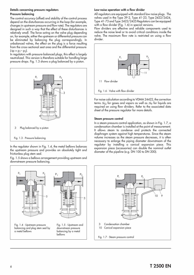
Details concerning pressure regulatorsPressure balancingThe control accuracy (offset) and stability of the control processdepend on the disturbances occurring in the loop (for example,changes in upstream pressure and flow rate). The regulators aredesigned in such a way that the effect of these disturbances isrelatively small. The force acting on the valve plug dependingon, for example, either the upstream or differential pressure canbe eliminated by balancing the plug correspondingly. Inunbalanced valves, the effect on the plug is a force resultingfrom the cross-sectional seat area and the differential pressure(Δp = p1– p2).In regulators with pressure-balanced plugs, this effect is largelyneutralized. This version is therefore suitable for handling largepressure drops. Fig. 1.3 shows a plug balanced by a piston.
In the regulator shown in Fig. 1.4, the metal bellows balancesthe upstream pressure and provides an absolutely tight andfrictionless plug stem seal.Fig. 1.5 shows a bellows arrangement providing upstream anddownstream pressure balancing.
Low-noise operation with a flow dividerAll regulators are equipped with standard low-noise plugs. Thevalves used in the Type 39-2, Type 41-23, Type 2422/2424,Type 41-73 and Type 2422/2425 Regulators can be equippedwith a flow divider (Fig. 1.6) in special versions.Flow dividers are effective and reliable components used toreduce the noise level or to avoid critical conditions inside thevalve. The maximum flow rate is restricted on using a flowdivider.
For noise calculation according to VDMA 24422, the correctionterms ΔLG for gases and vapors as well as ΔLF for liquids arerequired on using flow dividers. Refer to the associated datasheet of the pressure regulator for more details.
Steam pressure controlIn a steam pressure control application, as shown in Fig. 1.7, acondensation chamber is installed at the point of measurement.It allows steam to condense and protects the connecteddiaphragm system against high temperatures. Since the steamvolume increases as the steam pressure decreases, it is oftennecessary to enlarge the piping diameter downstream of theregulator by installing a conical expansion piece. Thisexpansion piece (accessories) can double the nominal outletdiameter of the pipeline (e.g. DN 100 to DN 200).
6 T 2500 EN
Fig. 1.3 · Pressure balancing
3 Plug balanced by a piston
Fig. 1.4 · Upstream pressurebalancing and plug stem seal bya metal bellows
Fig. 1.5 · Upstream anddownstream pressurebalancing by a metalbellows
Fig. 1.6 · Valve with flow divider
11 Flow divider
Fig. 1.7 · Steam pressure control
3 Condensation chamber10 Conical expansion piece
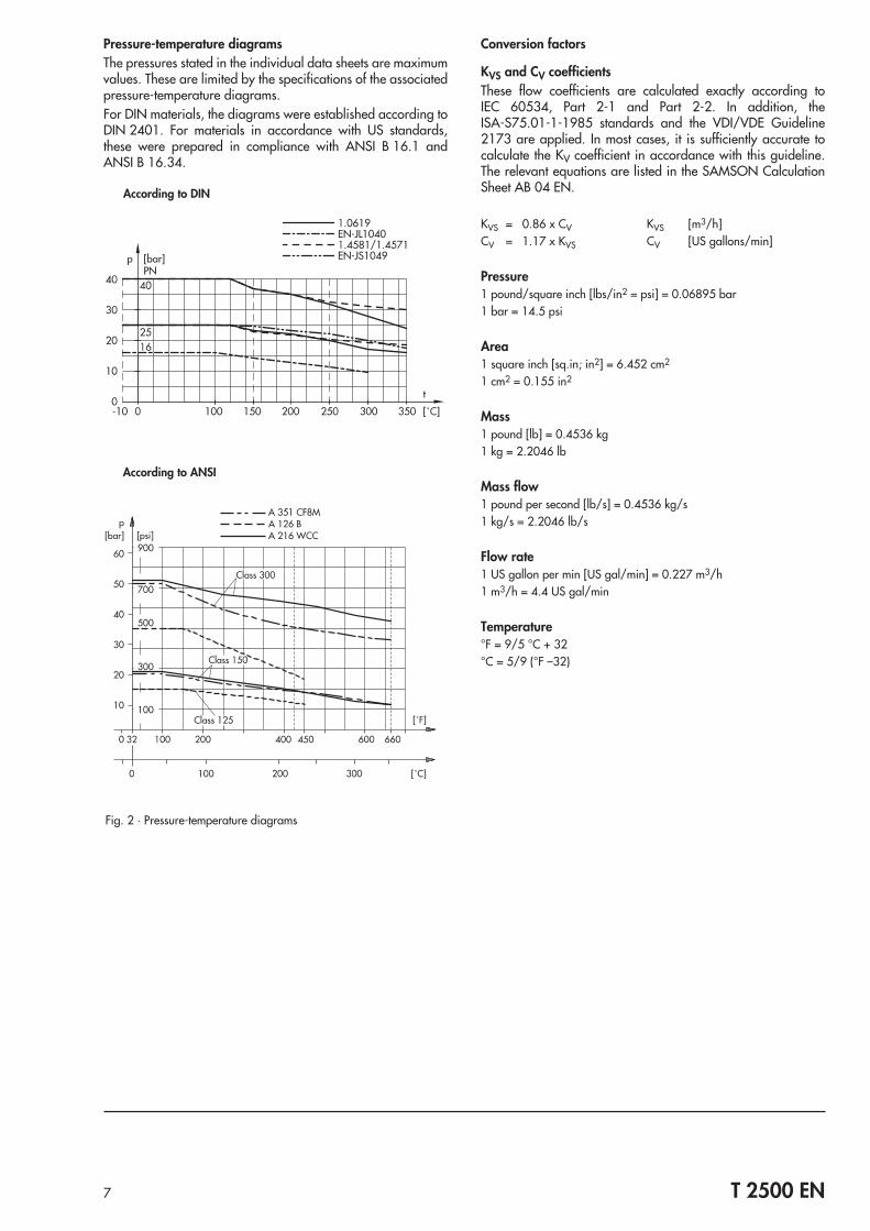
Pressure-temperature diagramsThe pressures stated in the individual data sheets are maximumvalues. These are limited by the specifications of the associatedpressure-temperature diagrams.For DIN materials, the diagrams were established according toDIN 2401. For materials in accordance with US standards,these were prepared in compliance with ANSI B 16.1 andANSI B 16.34.
Conversion factors
KVS and CV coefficientsThese flow coefficients are calculated exactly according toIEC 60534, Part 2-1 and Part 2-2. In addition, theISA-S75.01-1-1985 standards and the VDI/VDE Guideline2173 are applied. In most cases, it is sufficiently accurate tocalculate the KV coefficient in accordance with this guideline.The relevant equations are listed in the SAMSON CalculationSheet AB 04 EN.
KVS = 0.86 x CV KVS [m3/h]CV = 1.17 x KVS CV [US gallons/min]
Pressure1 pound/square inch [lbs/in2 = psi] = 0.06895 bar1 bar = 14.5 psi
Area1 square inch [sq.in; in2] = 6.452 cm2
1 cm2 = 0.155 in2
Mass1 pound [lb] = 0.4536 kg1 kg = 2.2046 lb
Mass flow1 pound per second [lb/s] = 0.4536 kg/s1 kg/s = 2.2046 lb/s
Flow rate1 US gallon per min [US gal/min] = 0.227 m3/h1 m3/h = 4.4 US gal/min
Temperature°F = 9/5 °C + 32°C = 5/9 (°F –32)
7 T 2500 EN
According to DIN
Fig. 2 · Pressure-temperature diagrams
According to ANSI
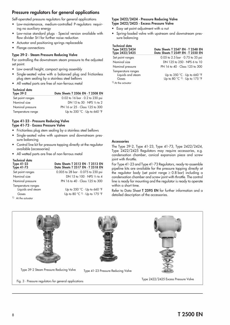
Pressure regulators for general applicationsSelf-operated pressure regulators for general applications• Low-maintenance, medium-controlled P-regulators requir-
ing no auxiliary energy• Low-noise standard plugs · Special version available with
flow divider St I for further noise reduction• Actuator and positioning springs replaceable• Flange connections
Type 39-2 · Steam Pressure Reducing ValveFor controlling the downstream steam pressure to the adjustedset point.• Low overall height, compact spring assembly• Single-seated valve with a balanced plug and frictionless
plug stem sealing by a stainless steel bellows• All wetted parts are free of non-ferrous metal
Technical dataType 39-2 Data Sheets T 2506 EN · T 2508 ENSet point ranges 0.02 to 16 bar · 0.2 to 230 psiNominal size DN 15 to 50 · NPS ½ to 2Nominal pressure PN 16 or 25 · Class 125 to 300Temperature range Up to 350 °C · Up to 660 °F
Type 41-23 · Pressure Reducing ValveType 41-73 · Excess Pressure Valve• Frictionless plug stem sealing by a stainless steel bellows• Single-seated valve with upstream and downstream pres-
sure balancing• Control line kit for pressure tapping directly at the regulator
available (accessories)• All wetted parts are free of non-ferrous metal
Technical dataType 41-23 Data Sheets T 2512 EN · T 2513 ENType 41-73 Data Sheets T 2517 EN · T 2518 ENSet point ranges 0.005 to 28 bar · 0.075 to 230 psiNominal size DN 15 to 100 · NPS ½ to 4Nominal pressure PN 16 to 40 · Class 125 to 300Temperature ranges
Liquids and steam Up to 350 °C · Up to 660 °FGases Up to 80 °C 1) · Up to 175 °F
1) At the actuator
Type 2422/2424 · Pressure Reducing ValveType 2422/2425 · Excess Pressure Valve• Easy set point adjustment with a nut• Spring-loaded valve with upstream and downstream pres-
sure balancing
Technical dataType 2422/2424 Data Sheets T 2547 EN · T 2548 ENType 2422/2425 Data Sheets T 2549 EN · T 2550 ENSet point ranges 0.05 to 2.5 bar · 0.75 to 35 psiNominal size DN 125 to 250 · NPS 6 to 10Nominal pressure PN 16 to 40 · Class 125 to 300Temperature ranges
Liquids and steam Up to 350 °C · Up to 660 °FGases Up to 80 °C 1) · Up to 175 °F
1) At the actuator
AccessoriesThe Type 39-2, Type 41-23, Type 41-73, Type 2422/2424,Type 2422/2425 Regulators may require accessories, e.g.condensation chamber, conical expansion piece and screwjoint with throttle.For Type 41-23 and Type 41-73 Regulators, ready-to-assemblepipeline kits are available for the pressure tapping directly atthe regulator body (set point range ≥ 0.8 bar) including acondensation chamber and screw joint with throttle. The controlline is ready for mounting and the regulator is ready to operatewithin a short time.Refer to Data Sheet T 2595 EN for further information and adetailed description of the accessories.
8 T 2500 EN
Fig. 3 · Pressure regulators for general applications
Type 39-2 Steam Pressure Reducing Valve Type 41-23 Pressure Reducing Valve
Type 2422/2425 Excess Pressure Valve
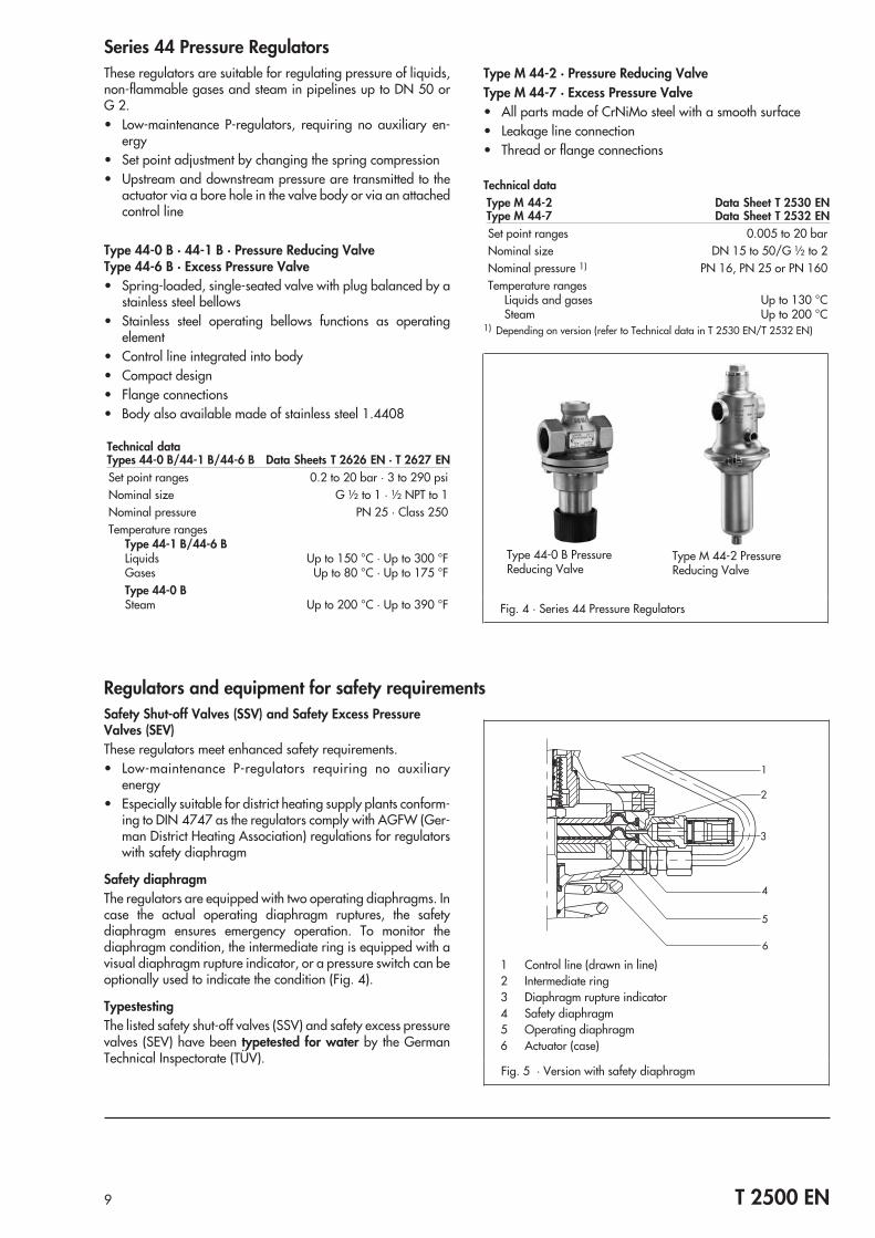
Series 44 Pressure RegulatorsThese regulators are suitable for regulating pressure of liquids,non-flammable gases and steam in pipelines up to DN 50 orG 2.• Low-maintenance P-regulators, requiring no auxiliary en-
ergy• Set point adjustment by changing the spring compression• Upstream and downstream pressure are transmitted to the
actuator via a bore hole in the valve body or via an attachedcontrol line
Type 44-0 B · 44-1 B · Pressure Reducing ValveType 44-6 B · Excess Pressure Valve• Spring-loaded, single-seated valve with plug balanced by a
stainless steel bellows• Stainless steel operating bellows functions as operating
element• Control line integrated into body• Compact design• Flange connections• Body also available made of stainless steel 1.4408
Technical dataTypes 44-0 B/44-1 B/44-6 B Data Sheets T 2626 EN · T 2627 ENSet point ranges 0.2 to 20 bar · 3 to 290 psiNominal size G ½ to 1 · ½ NPT to 1Nominal pressure PN 25 · Class 250Temperature ranges
Type 44-1 B/44-6 BLiquids Up to 150 °C · Up to 300 °FGases Up to 80 °C · Up to 175 °FType 44-0 BSteam Up to 200 °C · Up to 390 °F
Type M 44-2 · Pressure Reducing ValveType M 44-7 · Excess Pressure Valve• All parts made of CrNiMo steel with a smooth surface• Leakage line connection• Thread or flange connections
Technical dataType M 44-2 Data Sheet T 2530 ENType M 44-7 Data Sheet T 2532 ENSet point ranges 0.005 to 20 barNominal size DN 15 to 50/G ½ to 2Nominal pressure 1) PN 16, PN 25 or PN 160Temperature ranges
Liquids and gases Up to 130 °CSteam Up to 200 °C
1) Depending on version (refer to Technical data in T 2530 EN/T 2532 EN)
9 T 2500 EN
Regulators and equipment for safety requirementsSafety Shut-off Valves (SSV) and Safety Excess PressureValves (SEV)These regulators meet enhanced safety requirements.• Low-maintenance P-regulators requiring no auxiliary
energy• Especially suitable for district heating supply plants conform-
ing to DIN 4747 as the regulators comply with AGFW (Ger-man District Heating Association) regulations for regulatorswith safety diaphragm
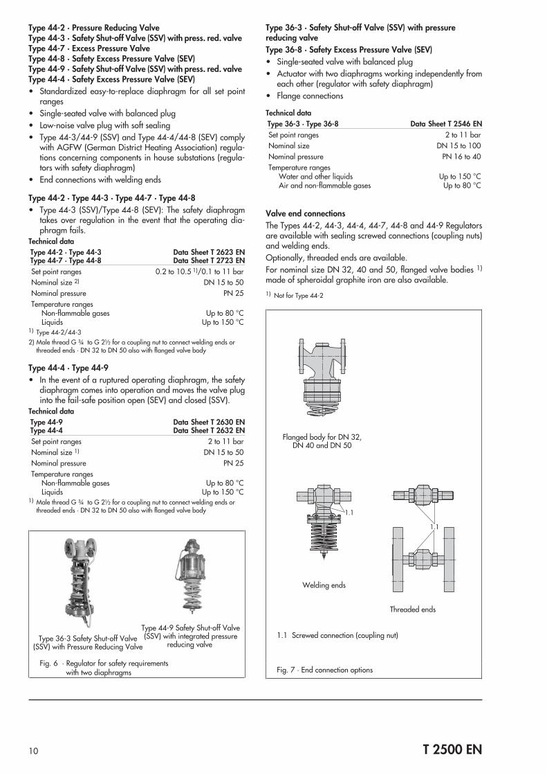
Safety diaphragmThe regulators are equipped with two operating diaphragms. Incase the actual operating diaphragm ruptures, the safetydiaphragm ensures emergency operation. To monitor thediaphragm condition, the intermediate ring is equipped with avisual diaphragm rupture indicator, or a pressure switch can beoptionally used to indicate the condition (Fig. 4).
TypestestingThe listed safety shut-off valves (SSV) and safety excess pressurevalves (SEV) have been typetested for water by the GermanTechnical Inspectorate (TÜV).
Fig. 4 · Series 44 Pressure Regulators
Type M 44-2 PressureReducing Valve
Type 44-0 B PressureReducing Valve
Fig. 5 · Version with safety diaphragm
1 Control line (drawn in line)2 Intermediate ring3 Diaphragm rupture indicator4 Safety diaphragm5 Operating diaphragm6 Actuator (case)
Type 44-2 · Pressure Reducing ValveType 44-3 · Safety Shut-off Valve (SSV) with press. red. valveType 44-7 · Excess Pressure ValveType 44-8 · Safety Excess Pressure Valve (SEV)Type 44-9 · Safety Shut-off Valve (SSV) with press. red. valveType 44-4 · Safety Excess Pressure Valve (SEV)• Standardized easy-to-replace diaphragm for all set point
ranges• Single-seated valve with balanced plug• Low-noise valve plug with soft sealing• Type 44-3/44-9 (SSV) and Type 44-4/44-8 (SEV) comply
with AGFW (German District Heating Association) regula-tions concerning components in house substations (regula-tors with safety diaphragm)
• End connections with welding ends
Type 44-2 · Type 44-3 · Type 44-7 · Type 44-8• Type 44-3 (SSV)/Type 44-8 (SEV): The safety diaphragm
takes over regulation in the event that the operating dia-phragm fails.
Technical dataType 44-2 · Type 44-3 Data Sheet T 2623 ENType 44-7 · Type 44-8 Data Sheet T 2723 ENSet point ranges 0.2 to 10.5 1)/0.1 to 11 barNominal size 2) DN 15 to 50Nominal pressure PN 25Temperature ranges
Non-flammable gases Up to 80 °CLiquids Up to 150 °C
1) Type 44-2/44-32) Male thread G ¾ to G 2½ for a coupling nut to connect welding ends or
threaded ends · DN 32 to DN 50 also with flanged valve body
Type 44-4 · Type 44-9• In the event of a ruptured operating diaphragm, the safety
diaphragm comes into operation and moves the valve pluginto the fail-safe position open (SEV) and closed (SSV).
Technical dataType 44-9 Data Sheet T 2630 ENType 44-4 Data Sheet T 2632 ENSet point ranges 2 to 11 barNominal size 1) DN 15 to 50Nominal pressure PN 25Temperature ranges
Non-flammable gases Up to 80 °CLiquids Up to 150 °C
1) Male thread G ¾ to G 2½ for a coupling nut to connect welding ends orthreaded ends · DN 32 to DN 50 also with flanged valve body
Type 36-3 · Safety Shut-off Valve (SSV) with pressurereducing valveType 36-8 · Safety Excess Pressure Valve (SEV)• Single-seated valve with balanced plug• Actuator with two diaphragms working independently from
each other (regulator with safety diaphragm)• Flange connections
Technical dataType 36-3 · Type 36-8 Data Sheet T 2546 ENSet point ranges 2 to 11 barNominal size DN 15 to 100Nominal pressure PN 16 to 40Temperature ranges
Water and other liquids Up to 150 °CAir and non-flammable gases Up to 80 °C
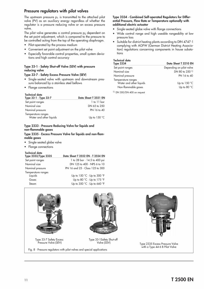
Valve end connectionsThe Types 44-2, 44-3, 44-4, 44-7, 44-8 and 44-9 Regulatorsare available with sealing screwed connections (coupling nuts)and welding ends.Optionally, threaded ends are available.For nominal size DN 32, 40 and 50, flanged valve bodies 1)
made of spheroidal graphite iron are also available.1) Not for Type 44-2
10 T 2500 EN
Fig. 6 · Regulator for safety requirementswith two diaphragms
Type 36-3 Safety Shut-off Valve(SSV) with Pressure Reducing Valve
Type 44-9 Safety Shut-off Valve(SSV) with integrated pressure
reducing valve
Fig. 7 · End connection options
1.1 Screwed connection (coupling nut)
Welding ends
Threaded ends
Flanged body for DN 32,DN 40 and DN 50
Pressure regulators with pilot valvesThe upstream pressure p1 is transmitted to the attached pilotvalve (PV) as an auxiliary energy regardless of whether theregulator is a pressure reducing valve or an excess pressurevalve.The pilot valve generates a control pressure pS dependent onthe set point adjustment, which is compared to the pressure tobe controlled acting from the top of the operating diaphragm.• Pilot-operated by the process medium• Convenient set point adjustment on the pilot valve• Especially favorable control properties, small system devia-
tions and high control accuracy
Type 33-1 · Safety Shut-off Valve (SSV) with pressurereducing valveType 33-7 · Safety Excess Pressure Valve (SEV)• Single-seated valve with upstream and downstream pres-
sure balanced by a stainless steel bellows• Flange connections
Technical dataType 33-1 · Type 33-7 Data Sheet T 2551 ENSet point ranges 1 to 11 barNominal size DN 65 to 250Nominal pressure PN 16 to 40Temperature ranges
Water and other liquids Up to 150 °C
Type 2333 · Pressure Reducing Valve for liquids andnon-flammable gasesType 2335 · Excess Pressure Valve for liquids and non-flam-mable gases• Single-seated globe valve• Flange connections
Technical dataType 2333/Type 2335 Data Sheet T 2552 EN · T 2554 ENSet point ranges 1 to 28 bar · 14.5 to 400 psiNominal size DN 125 to 400 · NPS 6 to 10Nominal pressure PN 16 and 25 · Class 125 to 300Temperature ranges
Liquids Up to 150 °C · Up to 300 °FGases Up to 80 °C · Up to 175 °FSteam Up to 350 °C · Up to 660 °F
Type 2334 · Combined Self-operated Regulators for Differ-ential Pressure, Flow Rate or Temperature optionally withadditional electric actuator• Single-seated globe valve with flange connections• Wide control range and high useable rangeablity at low
pressure loss• Suitable for district heating plants according to DIN 4747-1
complying with AGFW (German District Heating Associa-tion) regulations concerning components in house substa-tions
Technical dataType 2334 Data Sheet T 3210 ENSet point ranges Depending on pilot valveNominal size DN 80 to 250 1)
Nominal pressure PN 16 to 40Temperature ranges
Water and other liquids Up to 150 °CNon-flammable gases Up to 80 °C
1) DN 300/DN 400 on request
11 T 2500 EN
Fig. 8 · Pressure regulators with pilot valves and special applications
Type 33-1Safety Shut-offValve (SSV)
Type 33-7 Safety ExcessPressure Valve (SEV) Type 2335 Excess Pressure Valve
with a Type 44-6 B Pilot Valve
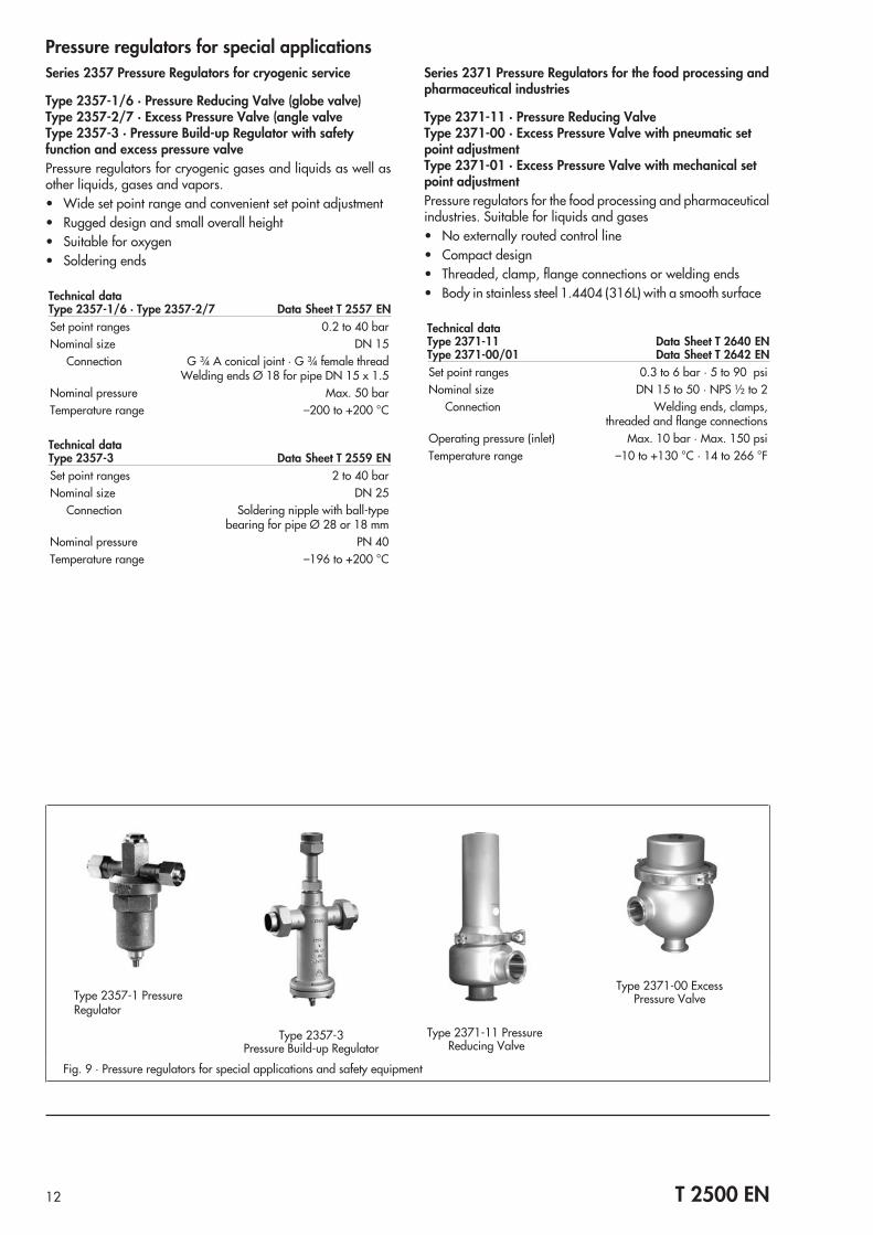
Pressure regulators for special applicationsSeries 2357 Pressure Regulators for cryogenic service
Type 2357-1/6 · Pressure Reducing Valve (globe valve)Type 2357-2/7 · Excess Pressure Valve (angle valveType 2357-3 · Pressure Build-up Regulator with safetyfunction and excess pressure valvePressure regulators for cryogenic gases and liquids as well asother liquids, gases and vapors.• Wide set point range and convenient set point adjustment• Rugged design and small overall height• Suitable for oxygen• Soldering ends
Technical dataType 2357-1/6 · Type 2357-2/7 Data Sheet T 2557 ENSet point ranges 0.2 to 40 barNominal size DN 15
Connection G ¾ A conical joint · G ¾ female threadWelding ends Ø 18 for pipe DN 15 x 1.5
Nominal pressure Max. 50 barTemperature range –200 to +200 °C
Technical dataType 2357-3 Data Sheet T 2559 ENSet point ranges 2 to 40 barNominal size DN 25
Connection Soldering nipple with ball-typebearing for pipe Ø 28 or 18 mm
Nominal pressure PN 40Temperature range –196 to +200 °C
Series 2371 Pressure Regulators for the food processing andpharmaceutical industries
Type 2371-11 · Pressure Reducing ValveType 2371-00 · Excess Pressure Valve with pneumatic setpoint adjustmentType 2371-01 · Excess Pressure Valve with mechanical setpoint adjustmentPressure regulators for the food processing and pharmaceuticalindustries. Suitable for liquids and gases• No externally routed control line• Compact design• Threaded, clamp, flange connections or welding ends• Body in stainless steel 1.4404 (316L) with a smooth surface
Technical dataType 2371-11 Data Sheet T 2640 ENType 2371-00/01 Data Sheet T 2642 ENSet point ranges 0.3 to 6 bar · 5 to 90 psiNominal size DN 15 to 50 · NPS ½ to 2
Connection Welding ends, clamps,threaded and flange connections
Operating pressure (inlet) Max. 10 bar · Max. 150 psiTemperature range –10 to +130 °C · 14 to 266 °F
12 T 2500 EN
Fig. 9 · Pressure regulators for special applications and safety equipment
Type 2357-1 PressureRegulator
Type 2357-3Pressure Build-up Regulator
Type 2371-00 ExcessPressure Valve
Type 2371-11 PressureReducing Valve
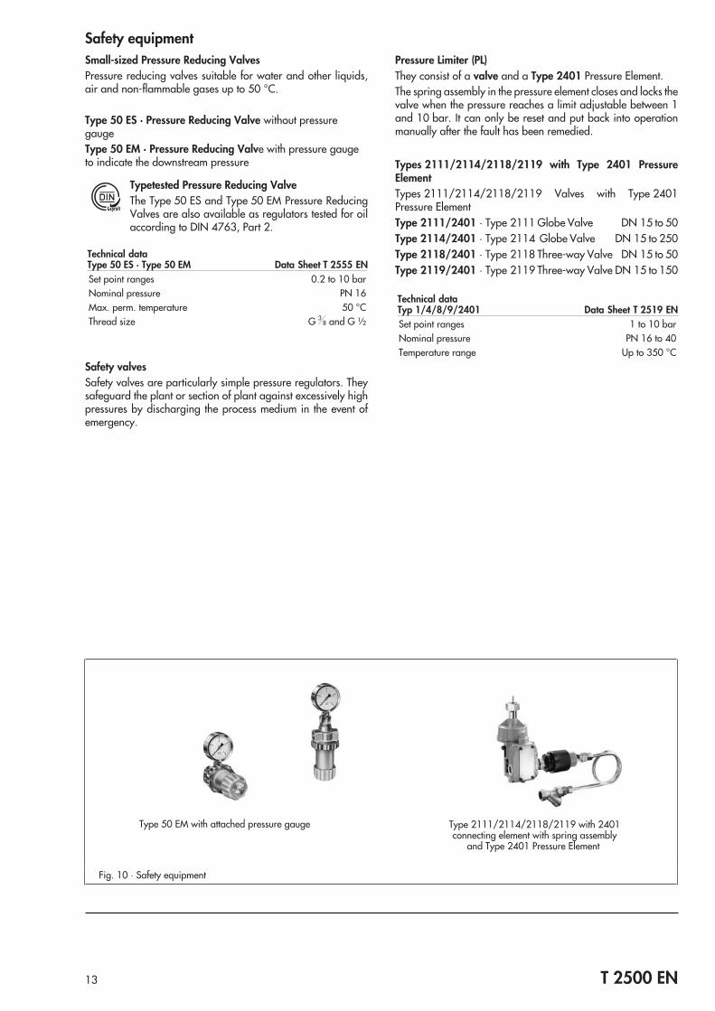
Safety equipmentSmall-sized Pressure Reducing ValvesPressure reducing valves suitable for water and other liquids,air and non-flammable gases up to 50 °C.
Type 50 ES · Pressure Reducing Valve without pressuregaugeType 50 EM · Pressure Reducing Valve with pressure gaugeto indicate the downstream pressure
Typetested Pressure Reducing ValveThe Type 50 ES and Type 50 EM Pressure ReducingValves are also available as regulators tested for oilaccording to DIN 4763, Part 2.
Technical dataType 50 ES · Type 50 EM Data Sheet T 2555 ENSet point ranges 0.2 to 10 barNominal pressure PN 16Max. perm. temperature 50 °CThread size G 3
8 and G ½
Safety valvesSafety valves are particularly simple pressure regulators. Theysafeguard the plant or section of plant against excessively highpressures by discharging the process medium in the event ofemergency.
Pressure Limiter (PL)They consist of a valve and a Type 2401 Pressure Element.The spring assembly in the pressure element closes and locks thevalve when the pressure reaches a limit adjustable between 1and 10 bar. It can only be reset and put back into operationmanually after the fault has been remedied.
Types 2111/2114/2118/2119 with Type 2401 PressureElementTypes 2111/2114/2118/2119 Valves with Type 2401Pressure ElementType 2111/2401 · Type 2111 Globe Valve DN 15 to 50Type 2114/2401 · Type 2114 Globe Valve DN 15 to 250Type 2118/2401 · Type 2118 Three-way Valve DN 15 to 50Type 2119/2401 · Type 2119 Three-way Valve DN 15 to 150
Technical dataTyp 1/4/8/9/2401 Data Sheet T 2519 ENSet point ranges 1 to 10 barNominal pressure PN 16 to 40Temperature range Up to 350 °C
13 T 2500 EN
Fig. 10 · Safety equipment
Type 50 EM with attached pressure gauge Type 2111/2114/2118/2119 with 2401connecting element with spring assembly
and Type 2401 Pressure Element
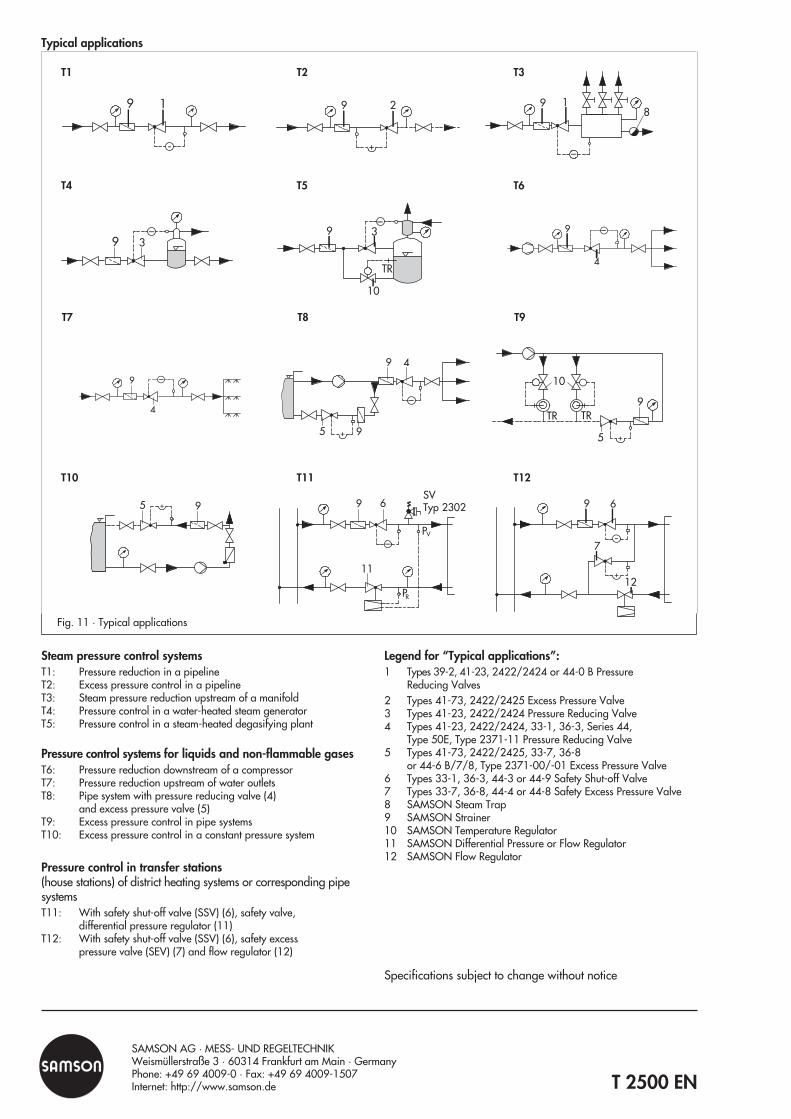
Steam pressure control systemsT1: Pressure reduction in a pipelineT2: Excess pressure control in a pipelineT3: Steam pressure reduction upstream of a manifoldT4: Pressure control in a water-heated steam generatorT5: Pressure control in a steam-heated degasifying plant
Pressure control systems for liquids and non-flammable gasesT6: Pressure reduction downstream of a compressorT7: Pressure reduction upstream of water outletsT8: Pipe system with pressure reducing valve (4)
and excess pressure valve (5)T9: Excess pressure control in pipe systemsT10: Excess pressure control in a constant pressure system
Pressure control in transfer stations(house stations) of district heating systems or corresponding pipesystemsT11: With safety shut-off valve (SSV) (6), safety valve,
differential pressure regulator (11)T12: With safety shut-off valve (SSV) (6), safety excess
pressure valve (SEV) (7) and flow regulator (12)
Legend for “Typical applications”:1 Types 39-2, 41-23, 2422/2424 or 44-0 B Pressure
Reducing Valves2 Types 41-73, 2422/2425 Excess Pressure Valve3 Types 41-23, 2422/2424 Pressure Reducing Valve4 Types 41-23, 2422/2424, 33-1, 36-3, Series 44,
Type 50E, Type 2371-11 Pressure Reducing Valve5 Types 41-73, 2422/2425, 33-7, 36-8
or 44-6 B/7/8, Type 2371-00/-01 Excess Pressure Valve6 Types 33-1, 36-3, 44-3 or 44-9 Safety Shut-off Valve7 Types 33-7, 36-8, 44-4 or 44-8 Safety Excess Pressure Valve8 SAMSON Steam Trap9 SAMSON Strainer10 SAMSON Temperature Regulator11 SAMSON Differential Pressure or Flow Regulator12 SAMSON Flow Regulator
Specifications subject to change without notice
T 2500 EN
SAMSON AG · MESS- UND REGELTECHNIKWeismüllerstraße 3 · 60314 Frankfurt am Main · GermanyPhone: +49 69 4009-0 · Fax: +49 69 4009-1507Internet: http://www.samson.de
Typical applications
Fig. 11 · Typical applications
9 1
-
9 2
+
9 18
_
39_ 9
4
_
9
4
_9 4
5 9+
_10
TR TR
5
9
+
95 + 9 6
11
PR
PV
SVTyp 2302
_
9 6
7
12
-
+
T10 T11 T12
T7 T8 T9
T4 T5 T6
T1 T2 T3