TEMPERATURE REGULATORS W91/W94 Series · Self-Operated Temperature Regulators 428 Jones...
18
Housing Assembly The housing consists of a cap and yoke constructed from precision die cast aluminum. This assembly ensures permanent alignment with the valve body, while protecting the bellows assembly. The yoke includes a set point scale used to reference the setting of the temperature adjustment screw. The entire housing is finished in a corrosion resistant, baked blue epoxy. CONNECTION CAPILLARY TUBING SENSING BULB ADJUSTING BAR SET POINT SCALE JAM NUTS PACKING NUT STAINLESS STEEL SEATS VALVE BODY DIAL THERMOMETER (Model W94) BELLOWS OVERRANGE PROTECTION SPRING RANGE ADJUSTMENT SPRING CAP ADJUSTMENT SCREW BUSHING TEMPERATURE ADJUSTMENT SCREW TEFLON V-RING PACKING VALVE STEM VALVE PLUG BONNET NUT YOKE 166 Design & Operation W91 – Non-Indicating W94 – Dial Thermometer W91/W94 Series TEMPERATURE REGULATORS Self-Operated Temperature Regulators 428 Jones Boulevard • Limerick Airport Business Center • Pottstown PA • 19464 • Tel: 610-495-5131 • Fax: 610-495-5134 www.watsonmcdaniel.com DIRECT-OPERATED REGULATING VALVES Watson McDaniel reserves the right to change the designs and/or materials of its products without notice. ©2010 Watson McDaniel Company
Transcript of TEMPERATURE REGULATORS W91/W94 Series · Self-Operated Temperature Regulators 428 Jones...

Housing Assembly
The housing consists of a cap and yoke constructed from precision die cast aluminum. This assemblyensures permanent alignment with the valve body, while protecting the bellows assembly. The yokeincludes a set point scale used to reference the setting of the temperature adjustment screw. The entirehousing is finished in a corrosion resistant, baked blue epoxy.
CONNECTION
CAPILLARY TUBING
SENSING BULB
ADJUSTING BAR
SET POINT SCALE
JAM NUTS
PACKING NUT
STAINLESS STEEL SEATS
VALVE BODY
DIAL THERMOMETER(Model W94)
BELLOWS
OVERRANGEPROTECTION SPRING
RANGE ADJUSTMENT SPRING
CAP
ADJUSTMENT SCREWBUSHING
TEMPERATURE ADJUSTMENT SCREW
TEFLON V-RING PACKING
VALVE STEM
VALVE PLUG
BONNET NUT
YOKE
166
Design & OperationW91 – Non-IndicatingW94 – Dial Thermometer
W91/W94 SeriesT E M P E R A T U R E R E G U L A T O R S
Self-Operated Temperature Regulators
428 Jones Boulevard • Limerick Airport Business Center • Pottstown PA • 19464 • Tel: 610-495-5131 • Fax: 610-495-5134www.watsonmcdaniel.com
DIRE
CT-O
PERA
TED
REG
ULAT
ING
VALV
ES
Watson McDaniel reserves theright to change the designs
and/or materials of itsproducts without notice.
©2010 Watson McDaniel Company

Description
The W91/W94 Self-Operating Temperature Regulator is a mechanically operated device designed to regulatesystem temperature by modulating the flow of a heating or cooling fluid in response to temperature changes.
Principles of Operation
The W91/W94 Temperature Regulator is a fully self-contained unit, requiring no external power source(i.e., compressed air or electricity). Regulation takes place when the sensing element (bulb) of the thermalsystem is exposed to changes in temperature. The thermal system is charged with a predeterminedamount of vapor fill, which, when heated, will cause a bellows within the unit’s actuator housing toexpand. As the bellows expands, it compresses a return spring while simultaneously moving the valvestem downward to stroke the valve. When the process temperature decreases (or in the event of thermalsystem failure), the return spring will move the valve stem upward to the “out” position. The choice ofvalve action (stem In-To-Close for Heating or stem In-To-Open for Cooling) will determine the system failure position.
Direct-Acting – HEATINGDirect-Acting actuators are designed to move the valve stem closed (in-to-close) as the control signal (temperature) increases.
Reverse-Acting – COOLINGReverse-Acting actuators are designed to move the valve stem open (in-to-open) as the control signal (temperature) increases.
Selecting a Temperature Regulator
The W91/W94 Temperature Regulator is recommended for controlling the flow on relatively stable systems, where small valve stroke modulations will correct temperature drift. Where sudden or large load changes, or rapid temperature changes occur, a pneumatically or electrically powered Control Valve should be specified. Please consult the Control Valves section of this catalog.
ActuatorThe actuator consists of the following assemblies: housing, bellows and spring return, and thermalsystem. Two actuator models are available:
• Model W91 is non-indicating.
• Model W94 is equipped with an integral dial thermometer to indicate sensing bulb temperature.
167
W91/W94 Series T E M P E R A T U R E R E G U L A T O R S
Self-Operated Temperature Regulators
Design & Operation
428 Jones Boulevard • Limerick Airport Business Center • Pottstown PA • 19464 • Tel: 610-495-5131 • Fax: 610-495-5134www.watsonmcdaniel.com
DIRECT -OPERATED
REGULATIN
GVALVES

Bellows & Spring Return Assembly
The accordion type bellows is corrosion resistant to provide accurate response for the life of the regulator. An adjusting bar is provided to turn the brass temperature adjustment screw, which compresses or expands the range adjustment spring, thereby setting the control point of the unit.
Thermal System Assembly
The thermal system (sensing bulb and capillary tubing) is available in copper (for best heat transfer)or 316 stainless steel (for corrosive applications) and can be ordered with a variety of protective coverings, including Teflon or stainless steel spiral armor. Capillary tubing lengths can be specifiedfrom 8 to 52 feet.
Integral Dial Thermometer
The integral dial thermometer (Model W94) displays the temperature at the sensing bulb. This allows for easy adjustment of the temperatureset point, as well as continuous monitoring of the application, withoutthe installation of an additional thermometer. The thermometer has a31/2" dialface and can be rotated and tilted for maximum readability.
Temperature Range
Nominal ranges from 20°F (-10°C) through 440°F (225°C) are available.The nominal range defines the entire temperature range of the unit. The service conditions and choice of valve style and action will determine the actual operating range (recommended working span) of the unit. The nominal range should be selected so that the set point falls within the recommended working span for the specified valve style and action. Models W91/W94 include an overrange protection spring,which allows the sensing bulb to be heated 100°F above the upper limitof the unit’s nominal range for system cleaning or temporary situations.
Accuracy
The W91/W94 Temperature Regulator is a “set-and-forget” regulating device. Once the proper controlpoint setting has been achieved, the unit requires virtually no adjustments and very little maintenance.Control point accuracy is dependent upon the sensing bulb location, load change size and speed, andvalve size. The sensing bulb must be installed in an area within the process that is most representative ofoverall process conditions. Care should be taken not to locate the bulb in close proximity to the valve, asthe regulator might respond to temperature changes before the process has had time to reach the controlpoint. Where sudden or large load changes occur, a pneumatically or electrically powered Control Valveshould be specified. Please consult the Control Valves section of this catalog.
Sensing Bulb Installation:
Care must be taken to ensurethat entire length of the sensingbulb is immersed into the medium at the sensing location.Partial immersion will result infaulty control. When the sensingbulb is installed into a pipeline,constant flow must be continuedthrough the line in order to maintain an active thermal signalto the bulb. Should a closedvalve cause stoppage of flow tothe bulb, a reduced bypass flowmust be installed to maintain thethermal signal.
The sensing bulb is designed tobe installed in either a horizontalposition or a vertical positionwith the tip down. If the tip mustbe installed upwards, pleasespecify when ordering, as a special bulb construction isrequired.
168
Design & Operation
W91/W94 SeriesT E M P E R A T U R E R E G U L A T O R S
Self-Operated Temperature Regulators
428 Jones Boulevard • Limerick Airport Business Center • Pottstown PA • 19464 • Tel: 610-495-5131 • Fax: 610-495-5134www.watsonmcdaniel.com
DIRE
CT-O
PERA
TED
REG
ULAT
ING
VALV
ES
Watson McDaniel reserves theright to change the designs
and/or materials of itsproducts without notice.
©2010 Watson McDaniel Company

Accuracy (continued)
Valve sizing also plays a major part in regulator performance. A valve that is too small will not be able toprovide the desired capacity during peak load conditions, while a valve that is too large may overshoot thecontrol point and operate with the valve plug too close to the seat, resulting in undue wear of the plug andseat. As part of a well-designed system, a properly sized valve (operating in the 60-90% open position) can control to within 2 to 5 °F.
Valve
W91/W94 Temperature Regulators are available with a wide variety of globe valves invarious styles, materials, connections and sizes.
Style
W91/W94 Regulator Valves are offered in single-seated, double-seated andthree-way designs:
• Single-Seated Balanced Valves are designed for heating applications wheretighter shut-off is required. The leakage rate is approximately 0.1% of themaximum capacity.
• Double-Seated Balanced Valves are designed for cooling applicationswhere a slight amount of leakage is normally acceptable. Since temperaturefluctuations may cause expansion and contraction across the seats, tightshut-off is not always possible. The leakage rate can be up to approximately0.5% of the maximum capacity.
• 3-Way Valves are used for mixing two flows together, or for diverting a flowto or around a device (bypass). In order to produce consistent flow quantityfor stable operation, the pressure drop across both flow paths (inlet to outlet)must be nearly equal.
3-Way Valves are of the Sleeve-Type (common port on the bottom). This type is most commonly used for diverting applications; however, due to itsdesign it can also be used for mixing applications. The Sleeve-Type design is constructed with an O-ring around the sleeve. This O-ring is suitable forwater or glycol type service, up to a maximum of 300˚F. A higher temperatureO-ring for use with other fluids, such as oil, or for temperatures up to 410˚F,is available. Consult factory.
Thermowell
For applications in which the process media may be corrosive or contained underpressure, the use of a thermowell is required to prevent damage to the sensing bulb. A thermowell will also facilitate the removal of the sensing bulb and thermal systemfrom the operating process. Thermowells are available in a variety of connection styles, materials and lengths.
CAUTION:Temperature Regulatorsare not consideredshut-off valves. Apressure surge mayforce a single seatedvalve plug open. TheW91/W94 TemperatureRegulator is a balancedequilibrium system atthe set point and provides no power totightly seat the valveplug. A separate powerdriven or hand actuatedvalve is required toensure tight shut-offwhen necessary.
CAUTION:3-Way Valves are notdesigned for use insteam applications.
169
W91/W94 Series T E M P E R A T U R E R E G U L A T O R S
Self-Operated Temperature Regulators
Design & Operation
428 Jones Boulevard • Limerick Airport Business Center • Pottstown PA • 19464 • Tel: 610-495-5131 • Fax: 610-495-5134www.watsonmcdaniel.com
Note: to ensureminimum responsetime, Heat TransferPaste should be appliedto the sensing portionof the bulb beforeinstallation.
DIRECT-OPERATED
REGULATIN
GVALVES

170
Action
Single-Seated Valves are available as stem In-To-Close (Normally Open) for Heating applications.Double-Seated Valves are available as stem In-To-Open (Normally Closed) for Cooling applications.3-Way Valves can be plumbed for either mixing or diverting service.
Temperature Regulator Valve Action
Application Stem Action Normal (Fail) Position
Heating In-To-Close Normally Open
Cooling In-To-Open Normally Closed
Body & Material and Connection
W91/W94 Temperature Regulators are available with bronze and cast iron valve bodies with Union, Flanged and Threaded connections.
Trim
Valve trim is composed of the stem and plug assembly, and the seats within the ports. Single and double-seated bronze bodied valves employ a stainless steel, tapered plug for enhanced modulation.The valve plug is both top and bottom guided to ensure positive seating alignment. 3-Way valves use a stainless steel sleeve and brass seating surface to change flow direction within the body.
Packing
Valves feature a self-energizing Teflon V-Ring packing, which reduces leakage around the valve stem. V-Ring packing is spring loaded to maintain proper compression and does not require manual adjustment.
Size
The proper sizing of a regulating valve is one of the most important factors in its selection. A valve that is too small will not be able to provide the desired capacity during peak load conditions, while a valve thatis too large may overshoot the control point and operate with the valve plug too close to the seat, resultingin undue wear of the plug and seat. The valve coefficient (Cv) is used todetermine the maximum capacity of a valve. From this value, a valve bodywith the appropriate port size can be selected. Port sizes from 1/8" through4" and connection sizes from 1/2" through 4" are available. Please consultthe Valve Selection section of this catalog.
Design & Operation
Valve Coefficient (Cv):The rated valve coefficientis used to describe the relative flow capacity of the valve based on standard test conditions.Please refer to the ValveSelection Section fordetailed information.
428 Jones Boulevard • Limerick Airport Business Center • Pottstown PA • 19464 • Tel: 610-495-5131 • Fax: 610-495-5134www.watsonmcdaniel.com
W91/W94 SeriesT E M P E R A T U R E R E G U L A T O R S
Self-Operated Temperature Regulators
Watson McDaniel reserves theright to change the designs
and/or materials of itsproducts without notice.
©2010 Watson McDaniel Company
DIRE
CT-O
PERA
TED
REG
ULAT
ING
VALV
ES

171
W91/W94 Series T E M P E R A T U R E R E G U L A T O R S
Self-Operated Temperature Regulators
W94 Used In A Drying Oven ApplicationW91 Used for Regulating Steam Flow In AnAutoclave/Sterilizer
W91 Used To Control Water Flow In A Grinding Mill ForTemperature Reduction
W94
Steam Supply
BypassHeat
Exchanger
Fuel OilStorage Tank
PumpF&TTrap
Steam Supply
Bypass
W94
F&TTrap
Finned Bulb forImproved Heat
Transfer
W94
Conveyor
Exhaust AirSteam
HeatCoil
Drying Oven
Fan
OutsideAir
GrindingMill
W91
Bypass
ColdWaterInlet
Hot OilInlet Heat Exchanger
Oil Cooler
W91
CoolingWaterInlet
Cool OilOutlet
TemperatureSensing Bulb
Cooling Water Outlet
W91
SteamSupply
ReliefValve
Autoclave
Bypass
ThermostaticAir Vent
F&TTrap
Typical Applications for Temperature Regulators
WaterFlow
TemperatureSensing
Bulb
CoolingWaterOutlet
Air FlowHeating
Coil
W91 Used to Reduce Oil Temperature In A Heat Exchanger
428 Jones Boulevard • Limerick Airport Business Center • Pottstown PA • 19464 • Tel: 610-495-5131 • Fax: 610-495-5134www.watsonmcdaniel.com
W94 Heating Fuel Oil To Proper Temperature W94 Elevating Temperature Of A Plating Or Finishing Tank
TemperatureSensing Bulb
TemperatureSensing Bulb
TemperatureSensing Bulb
DIRECT-OPERATED
REGULATIN
GVALVES

ValveBody
Thermal System:Capillary &
Sensing Bulb
Indicating Dial(Model W94 only)
Actuator
172
W91/W94 SeriesT E M P E R A T U R E R E G U L A T O R S
Self-Operated Temperature Regulators
428 Jones Boulevard • Limerick Airport Business Center • Pottstown PA • 19464 • Tel: 610-495-5131 • Fax: 610-495-5134www.watsonmcdaniel.com
The W91 & W94 Self-Operating Temperature Regulators are the preferred choice of original equipment manufacturers, mechanical contractors and specifying engineers. These regulators require no external power source and are ideal for regulating the temperature of tanks, processstreams and various types of industrial equipment. The Actuator is noted for itsrugged die-cast aluminum housing, fullyenclosed bellows assembly and internal overrange protection.
Model W91 (without indicating dial) features a lower profile and should be specified where space constraints may be an issue.
Model W94 (with indicating dial) will allow the operator to verify the process temperature and to aid in temperature adjustment.
Thermowells:For applications in which the process media may be corrosive or contained under pressure,the use of a thermowell is required to preventdamage to the sensing bulb. A thermowell willalso facilitate the removal of the sensing bulband thermal system from the operatingprocess.
Self-Operating Design
Indicating & Non-Indicating Models Available
Heavy Duty Die CastAluminum Housing
1/2" thru 4" Valve Sizes
Fully Enclosed Bellows
Internal Overrange protection
Watson McDaniel reserves theright to change the designs
and/or materials of itsproducts without notice.
©2010 Watson McDaniel Company
HOW TO ORDER
Models Temperature Range Capillary Length Bulb Valve Body Selection
W91 Non-Indicating 01 – 14 08 8 Feet (std) S15 (brass bulb) Refer to Valve Body SectionW94 Indicating Dial Refer to Temperature 12 12 Feet (standard)
Range Chart 16 16 Feet (Omit this selection20 20 Feet S16 (stainless bulb) if purchasing Actuator only)24 24 Feet
Note: Thermowells are ordered separately. See page 175 for model numbers & lengths.
Explanation of W91 06 08 S15 175-13Model Number: model temp. cap. bulb valve
range length type body
Model Number: W910608S15175-13
How to write proper model number:
DIRE
CT-O
PERA
TED
REG
ULAT
ING
VALV
ES

Dimensions: inches [mm]
173
W91/W94 Series T E M P E R A T U R E R E G U L A T O R S
Self-Operated Temperature Regulators
Model W91/W94Service Water, Steam, Other LiquidsSizes 1/2”– 4”Connections Threaded, Union Ends, 125# FLG
250# FLG (optional)Body Material 1/2” – 11/2” Bronze/Stainless Steel
2” Cast Iron (Direct-acting)2” Bronze (Reverse-acting)21/2” – 4” Cast Iron
Seat Material Stainless SteelMax. Inlet Pressure 250 PSIG
428 Jones Boulevard • Limerick Airport Business Center • Pottstown PA • 19464 • Tel: 610-495-5131 • Fax: 610-495-5134www.watsonmcdaniel.com
W91Non-IndicatingActuator
9.00[228]
Ø3.63[92]
Ø3.67[93]
4.92[125]
9.00[228]
Ø3.63[92]
W94IndicatingActuator
S p e c i f i c a t i o n sActuator Models
W91 - Non-Indicating W94 - Indicating Dial
Dial Thermometer31/2" dial, stainless steel case, swivel and angle adjustment (Model W94 only)
Housing Die cast aluminum, epoxy powder coated blue finish
Bellows High pressure brass, corrosionresistant, tin plated finish
Overrange ProtectionUpper range limit +100°F for temporary situations
Approximate Shipping WeightActuatorW91 6.0 lbs [2.7 kg]W94 6.6 lbs [3.0 kg]ValveSee Valve Selection tables
DIRECT-OPERATED
REGULA TIN
GVALVES
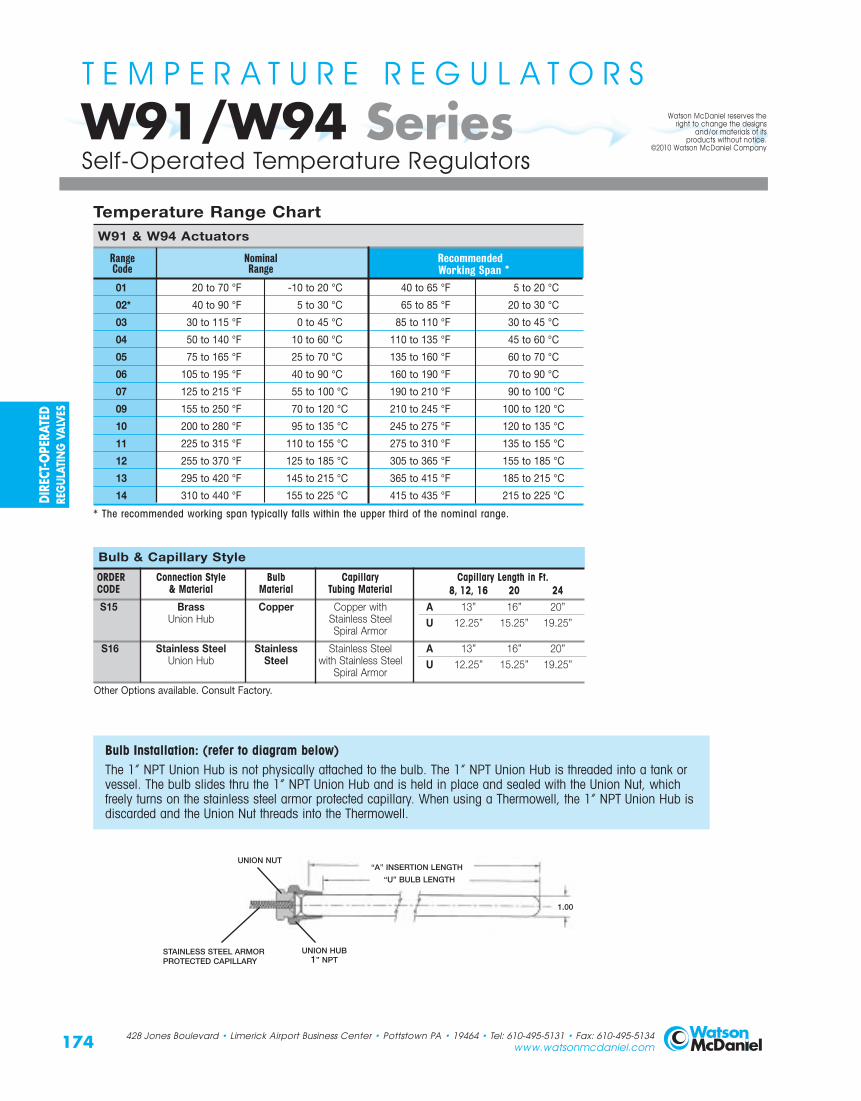
Temperature Range ChartW91 & W94 Actuators
Range Nominal Recommended Code Range Working Span *
01 20 to 70 °F -10 to 20 °C 40 to 65 °F 5 to 20 °C
02* 40 to 90 °F 5 to 30 °C 65 to 85 °F 20 to 30 °C
03 30 to 115 °F 0 to 45 °C 85 to 110 °F 30 to 45 °C
04 50 to 140 °F 10 to 60 °C 110 to 135 °F 45 to 60 °C
05 75 to 165 °F 25 to 70 °C 135 to 160 °F 60 to 70 °C
06 105 to 195 °F 40 to 90 °C 160 to 190 °F 70 to 90 °C
07 125 to 215 °F 55 to 100 °C 190 to 210 °F 90 to 100 °C
09 155 to 250 °F 70 to 120 °C 210 to 245 °F 100 to 120 °C
10 200 to 280 °F 95 to 135 °C 245 to 275 °F 120 to 135 °C
11 225 to 315 °F 110 to 155 °C 275 to 310 °F 135 to 155 °C
12 255 to 370 °F 125 to 185 °C 305 to 365 °F 155 to 185 °C
13 295 to 420 °F 145 to 215 °C 365 to 415 °F 185 to 215 °C
14 310 to 440 °F 155 to 225 °C 415 to 435 °F 215 to 225 °C
* The recommended working span typically falls within the upper third of the nominal range.
174
W91/W94 Series T E M P E R A T U R E R E G U L A T O R S
Self-Operated Temperature Regulators
428 Jones Boulevard • Limerick Airport Business Center • Pottstown PA • 19464 • Tel: 610-495-5131 • Fax: 610-495-5134www.watsonmcdaniel.com
Bulb & Capillary Style
ORDER Connection Style Bulb Capillary Capillary Length in Ft.CODE & Material Material Tubing Material 8, 12, 16 20 24S15 Brass Copper Copper with A 13” 16” 20”
Union Hub Stainless Steel U 12.25” 15.25” 19.25”Spiral Armor
S16 Stainless Steel Stainless Stainless Steel A 13” 16” 20”Union Hub Steel with Stainless Steel U 12.25” 15.25” 19.25”
Spiral Armor
Other Options available. Consult Factory.
Watson McDaniel reserves theright to change the designs
and/or materials of itsproducts without notice.
©2010 Watson McDaniel Company
“A” INSERTION LENGTH
1.00
UNION HUB1” NPT
UNION NUT
STAINLESS STEEL ARMOR PROTECTED CAPILLARY
“U” BULB LENGTH
Bulb Installation: (refer to diagram below)The 1” NPT Union Hub is not physically attached to the bulb. The 1” NPT Union Hub is threaded into a tank orvessel. The bulb slides thru the 1” NPT Union Hub and is held in place and sealed with the Union Nut, whichfreely turns on the stainless steel armor protected capillary. When using a Thermowell, the 1” NPT Union Hub isdiscarded and the Union Nut threads into the Thermowell.
DIRE
CT-O
PERA
TED
REG
ULAT
ING
VALV
ES

Notes: 1) Other connections and lengths may be available, consult factory.2) External pressure rating on Brass is 500 PSI max.3) External pressure rating on 316 SS is 1000 PSI max.
For applications in which the process media may be corrosive or contained under pressure, the use of a thermowell is required to prevent damage to the sensing bulb. A thermowell will also facilitate the removal of the sensing bulb andthermal system from the operating process. Because the sensing bulb is isolated from the fluid, this allows the sensingbulb to be removed without having to drain the liquid below the bulb insertion point.
175
W91/W94 Series T E M P E R A T U R E R E G U L A T O R S
Self-Operated Temperature Regulators
428 Jones Boulevard • Limerick Airport Business Center • Pottstown PA • 19464 • Tel: 610-495-5131 • Fax: 610-495-5134www.watsonmcdaniel.com
Dimensions (inches)
Thermowell Selection
THERMOWELLS - Model Numbers & Lengths
Brass Stainless Steel Nominal “A” INSERTION LENGTH (in.) Capillary LengthModel No. Model No. Length BULB THERMOWELL in Feet536-S2 536-S6 13" 12.25 13.00 8, 12 or 16536-SE2 536-SE6 16" 15.25 16.00 20536-WE2 536-WE6 20" 19.25 20.00 24
“A” INSERTION LENGTH
11/4” NPT HUB
1.13
Note: to ensure minimum responsetime, Heat TransferPaste should be appliedto the sensing portionof the bulb beforeinstallation.
“A” INSERTION LENGTH
1.00
UNION HUB 1” NPT (is not permanently fastened to Bulb)*
UNION NUT
STAINLESS STEEL ARMOR PROTECTED CAPILLARY
“U” BULB LENGTH
BULB
BULB inside THERMOWELL
THERMOWELL
11/4” NPT HUB (is part of Thermowell)
* Included with Bulb; discard when using Thermowell DIRECT -O
PERATEDREG
ULATING
VALVES

A(UNION)
B
A
Stem In-To-Closefor Heating
428 Jones Boulevard • Limerick Airport Business Center • Pottstown PA • 19464 • Tel: 610-495-5131 • Fax: 610-495-5134www.watsonmcdaniel.com
W91/W94 SeriesT E M P E R A T U R E R E G U L A T O R S
Single Seated Valve Bodies
Single Seat • 1/2” – 4”
HEATINGDimensions in inches
176
THREADED & UNION FLANGED
UNIONNUT
B
A(NPT)
C C
SpecificationsBody Material Trim Material Connection Pressure & Temperature Rating1/2”- 11/2” Bronze/Stainless Stainless Steel Threaded or Malleable Iron Union Ends 125 PSI @ 450°F
2” Cast Iron Stainless Steel Threaded 250 PSI @ 450°F
2” - 4” Cast Iron Stainless Steel125# Flanged 125 PSI @ 450°F
250# Flanged 250 PSI @ 450°F
Valve Body SelectionValve Body Number Size Maximum Dimensions Approx.
(In-To-Close Heating) Connection Capacity Close-Off Pressure A A A A B C Ship. Wt.NPT Union NPT Cv (PSI ∆P) Threaded 125# FLG 250# FLG Union (lbs) [kg]
175-12-N 175-12-U 1/2" 3.2 250 4.125 x x 6.50 2.375 2.12 14 [6.35]
175-13-N 175-13-U 3/4" 6.3 250 4.125 x x 6.50 2.375 2.12 14 [6.35]
175-14-N 175-14-U 1" 10.8 200 4.125 x x 7.00 2.375 2.12 14 [6.35]
175-15-N 175-15-U 11/4" 15.9 200 4.81 x x 7.50 3.25 2.50 17 [7.7]
175-16-N 175-16-U 11/2" 22.4 200 5.19 x x 8.00 3.50 2.69 18 [8.2]
175-17-N 2" 33.1 150 9.50 x x x 5.75 4.75 50 [22.7]
175-17-125 175-17-250 2" 33.1 150 – x 10.375 10.875 x 5.75 4.75 80 [36.3]
175-18-125 175-18-250 21/2" 47.5 65 150 x 10.625 11.25 x 7.00 5.00 96 [43.6]
175-19-125 175-19-250 3" 68.2 50 150 x 10.875 11.625 x 8.00 5.75 110 [49.9]
175-20-125 175-20-250 4" 109.5 40 150 x 10.50 13.125 x 8.75 6.50 160 [72.6]
Note: For 21/2” - 4” sizes, consult factory for proper actuators.
FLANGED125# 250#
ActuatorMounting Surface
ActuatorMounting Surface
FLOWFLOW
Standard Special
DIRE
CT-O
PERA
TED
REG
ULAT
ING
VALV
ES
Valve Type

CAPACIT IES – Steam (lbs/hr) SINGLE SEATED VALVESSize & Valve Body Number
1/2" 3/4" 1" 11/4" 11/2" 2" 21/2" 3" 4"
175-12 175-13 175-14 175-15 175-16 175-17 175-18 175-19 175-20
1 91 180 309 454 640 946 1357 1949 3129
3 103 203 348 512 722 1066 1530 2197 3527
5 115 226 387 570 803 1187 1703 2445 3926
10 144 283 486 715 1007 1488 2135 3066 4922
15 173 341 584 859 1211 1789 2568 3686 5919
20 202 398 682 1004 1415 2090 3000 4307 6915
25 231 455 780 1149 1618 2392 3432 4928 7912
30 260 513 879 1294 1822 2693 3864 5548 8908
40 319 627 1075 1583 2230 3295 4729 6790 10,901
50 377 742 1272 1872 2638 3898 5593 8031 12,894
60 435 857 1468 2162 3045 4500 6458 9272 14,887
70 493 971 1665 2451 3453 5102 7322 10,513 16,880
80 552 1086 1861 2740 3861 5705 8187 11,755 18,873
90 610 1200 2058 3030 4268 6307 9051 12,996 20,866
100 668 1315 2255 3319 4676 6910 9916 14,237 22,859
125 814 1602 2746 4043 5695 8416 12,077 17,340 27,841
150 959 1888 3237 4766 6714 9922 14,238 20,443 32,823
175 1105 2175 3729 5490 7734
200 1250 2462 4220 6213 8753
250 1542 3035
Notes: 1) For reduced-port 1/2” valves, consult factory. 2) All steam capacities based on Critical Drop (Choked Flow).
CAPACIT IES – Water (GPM) SINGLE SEATED VALVESSize & Valve Body Number
1/2” 3/4” 1” 11/4” 11/2” 2” 21/2” 3” 4”175W-12 175W-13 175W-14 175W-15 175W-16 175W-17 175W-18 175W-19 175W-20
1 3.2 6.3 11 16 22 33 48 68 1103 5.5 11 19 28 39 57 82 118 1905 7.2 14 24 36 50 74 106 152 24510 10 20 34 50 71 105 150 216 34615 12 24 42 62 87 128 184 264 42420 14 28 48 71 100 148 212 305 49025 16 32 54 80 112 166 238 341 54830 18 35 59 87 123 181 260 374 60040 20 40 68 101 142 209 300 431 69350 23 45 76 112 158 234 336 482 77460 25 49 84 123 174 256 368 528 84870 27 53 90 133 187 277 397 571 91680 29 56 97 142 200 296 425 610 97990 30 60 102 151 213 314 451 647 1039100 32 63 108 159 224 331 475 682 1095125 36 70 121 178 250 370 531 762 1224150 39 77 132 195 274 405 582 835 1341175 42 83 143 210 296200 45 89 153 225 317250 51 100
Note: When 175 Type SingleSeated Valves are used with water,add W to the Valve Body Number.
Example: 175-17-N becomes 175W-17-N
InletPressure(PSIG)
Pressure(PSI ∆P)
Note: Verify that Maximum Close-Off Pressure for 2” - 4” models does not exceed max rating for selected Valve BodyNumber and Type. (Refer toValve Body Number chart onprevious page)
Note: Verify that Maximum Close-Off Pressure for 2” - 4” models does not exceed max rating for selected Valve Body Number and Type. (Refer to Valve Body Number chart on previous page)
177
W91/W94 Series T E M P E R A T U R E R E G U L A T O R S
Capacity Chart for Single Seated Valves
428 Jones Boulevard • Limerick Airport Business Center • Pottstown PA • 19464 • Tel: 610-495-5131 • Fax: 610-495-5134www.watsonmcdaniel.com
Watson McDaniel reserves theright to change the designsand/or materials of itsproducts without notice.©2010 Watson McDaniel Company
DIRECT-OPERATED
REGULATIN
GVALVES

W91/W94 SeriesT E M P E R A T U R E R E G U L A T O R S
Steam Required for Heating Water
178 428 Jones Boulevard • Limerick Airport Business Center • Pottstown PA • 19464 • Tel: 610-495-5131 • Fax: 610-495-5134www.watsonmcdaniel.com
Watson McDaniel reserves theright to change the designs
and/or materials of itsproducts without notice.
©2010 Watson McDaniel Company
CAPACITY FORMULAS FOR STEAM LOADSWhen BTU Load is Known Capacity of = BTU
steam required 1000(lbs/hr)
When Square Feet Equivalent Capacity of Direct Radiation (EDR) is Known steam required = Sq. ft. of EDR
(lbs/hr) 4When Heating Water with Steam Capacity of
steam required = GPM x Temp Rise °F(lbs/hr) 2
When Heating Fuel Oil with Steam Capacity of steam required = GPM x Temp Rise °F(lbs/hr) 4
When Heating Air with Steam Coils Capacity of steam required = CFM x Temp Rise °F(lbs/hr) 900
Steam flow required through a temperature regulator (lbs/hr) to heat a specified number of gallons of water per hour (gal/hr)
TABLE 1- Steam Flow Required in Pounds Per Hour (lbs/hr)Temp ` Temp
Increase Increase(˚F) 25 50 100 200 300 500 700 1000 2000 4000 10,000 20,000 (˚F)
5° 1 2 4 8 12 21 29 41 83 166 415 830 5°10° 2 4 8 16 25 41 58 83 166 332 830 1660 10°15° 3 6 12 25 37 62 87 124 249 498 1245 2490 15°20° 4 8 17 33 50 83 116 166 332 664 1660 3320 20°25° 5 10 20 42 62 104 145 207 415 830 2075 4150 25°30° 6 12 25 50 75 124 174 249 498 996 2490 4980 30°40° 8 16 33 66 100 166 232 332 664 1328 3320 6640 40°50° 10 21 42 83 124 207 290 415 830 1660 4150 8300 50°60° 12 25 50 100 149 249 348 498 996 1992 4980 9960 60°70° 15 29 58 116 174 290 407 581 1162 2324 5810 11,620 70°80° 17 33 67 133 199 332 465 664 1328 2656 6640 13,280 80°90° 19 38 75 149 224 373 523 747 1494 2988 7470 14,940 90°100° 21 42 83 166 249 415 581 830 1660 3320 8300 16,600 100°115° 24 48 95 191 286 477 668 955 1909 3818 9544 19,088 115°130° 27 54 108 216 324 539 755 1079 2158 4316 10,790 21,580 130°145° 30 60 120 241 361 601 842 1200 2400 4812 12,030 24,060 145°160° 33 66 133 266 398 664 929 1328 2656 5312 13,280 26,560 160°175° 36 72 145 290 436 726 1017 1452 2900 5810 14,524 29,048 175°200° 41 83 166 332 498 830 1162 1660 3320 6640 16,600 33,200 200°225° 47 94 187 374 560 934 1307 1867 3735 7470 18,680 37,360 225°250° 52 104 207 415 622 1037 1452 2075 4150 8300 20,750 41,500 250°
Gallons of Water per Hour To Be Heated
HEATING WATER: The amount of steam required to heat water can be found using chart above.Example: To heat 1000 gallons per hour of water from 40˚F to 140˚F (Temp. increase 100˚F) requires 830 lbs/hr of steam.
HEATING FUEL OIL: The amount of steam required to heat fuel oil is half of that to heat water. Use half the value found in chart above.Example: To heat 1000 gallons per hour of fuel oil from 40˚F to 140˚F (Temp. increase 100˚F) requires 415 lbs/hr of steam.
DIRE
CT-O
PERA
TED
REG
ULAT
ING
VALV
ES

C
B
A
FLOW
W91/W94 SeriesT E M P E R A T U R E R E G U L A T O R S
Double Seated Valve BodiesDimensions in inches [mm] Double Seat • 3/4” – 4”
A
C
B
FLOW
I
C
B
A2” – 4”
FLANGED
Stem In-To-Openfor Cooling
C
B
SpecificationsBody Material Trim Material Trim Style Connection Pressure & Temperature Rating
3/4” - 2” Bronze Stainless Steel Threaded with Malleable Iron Union Ends 250 PSI @ 410°F (210°C)
21/2” - 4” Cast Iron Stainless Steel 125# Flanged 125 PSI @ 350°F (149°C)
Valve Body Selection – Threaded
Valve Body Number Size Maximum ApproximateClose-Off Pressure Dimensions Shipping Wt.
(In-To-Open Cooling) Connection (NPT) Nominal Port Cv (PSI ∆P) A B C (lbs) [kg]
A24 3/4 3/4" 8 250 5.6 [142] 2.3 [58] 2.3 [58] 5.0 lbs [2.25 kg]
A33 1 1" 12 250 6.0 [152] 2.3 [58] 2.3 [58] 6.1 lbs [2.75 kg]
A44 11/4 11/4" 21 250 7.2 [183] 2.6 [66] 2.6 [66] 10.1 lbs [4.55 kg]
A55 11/2 11/2" 30 250 7.7 [196] 2.6 [66] 2.6 [66] 11.1 lbs [5.00 kg]
A66 2 2" 47 250 8.6 [218] 3.1 [79] 3.1 [79] 17.0 lbs [7.65 kg]
Capacity
Valve Body Selection – Flanged
Valve Body Number Size Maximum ApproximateClose-Off Pressure Dimensions Shipping Wt.
(In-To-Open Cooling) Connection Nominal Port Cv (PSI ∆P) A B C (lbs) [kg]
B74 21/2" 21/2" 69 65 7.8 [198] 4.8 [122] 5.4 [137] 45 lbs [20 kg]
B79 3" 3" 90 50 9.0 [229] 5.0 [127] 5.6 [142] 70 lbs [32 kg]
B84 4" 4" 196 40 11.4 [290] 6.3 [160] 6.5 [165] 100 lbs [45 kg]
Capacity
179428 Jones Boulevard • Limerick Airport Business Center • Pottstown PA • 19464 • Tel: 610-495-5131 • Fax: 610-495-5134www.watsonmcdaniel.com
COOLING
ActuatorMounting Surface
ActuatorMounting Surface
FLOW
A3/4” – 2” UNION
FLOW
DIRECT-OPERATED
REGULATIN
GVALVES

W91/W94 SeriesT E M P E R A T U R E R E G U L A T O R S
Capacity Chart for Double Seated Valves
CAPACIT IES – Water (GPM) DOUBLE SEATED VALVESSize, Valve Body Number & Coefficient (Cv)
Pressure3/4” 1” 11/4” 11/2” 2” 21/2” 3” 4”Drop
(PSI ∆P) A24 ITO A33 IT0 A44 IT0 A55 IT0 A66 IT0 B74 ITO B79 ITO B84 ITOCv = 8 Cv = 12 Cv = 21 Cv = 30 Cv = 47 Cv = 69 Cv = 90 Cv = 196
1 8 12 21 30 47 69 90 1963 14 21 36 52 81 120 156 339
5 18 27 47 67 105 154 201 438
10 25 38 66 95 149 218 285 620
15 31 46 81 116 182 267 349 759
20 36 54 94 134 210 309 402 877
25 40 60 105 150 235 345 450 980
30 44 66 115 164 257 378 493 1074
40 51 76 133 190 297 436 569 1240
50 57 85 148 212 332 488 636
60 62 93 163 232 364
70 67 100 176 251 393
80 72 107 188 268 420
90 76 114 199 285 446
100 80 120 210 300 470
125 89 134 235 335 525
150 98 147 257 367 576
175 106 159 278 397 622
200 113 170 297 424 665
225 120 180 315 450 705
250 126 190 332 474 743
ITO = In-to-Open
180 428 Jones Boulevard • Limerick Airport Business Center • Pottstown PA • 19464 • Tel: 610-495-5131 • Fax: 610-495-5134www.watsonmcdaniel.com
Watson McDaniel reserves theright to change the designs
and/or materials of itsproducts without notice.
©2010 Watson McDaniel Company
COOLING
DIRE
CT-O
PERA
TED
REG
ULAT
ING
VALV
ES

STEM @ 0% IN
STEM @ 50% IN
STEM @ 100% IN
STEM @ 0% IN
STEM @ 50% IN
STEM @ 100% IN
Dimensions in inches [mm]
SpecificationsBody Material Trim Material Connection Pressure & Temperature Rating
Bronze Bronze Threaded with Malleable Iron Union Ends 250 PSI @ 300°F (149°C)
Valve Body SelectionMaximum
Valve Body NumberSize
Close-Off Pressure Dimensions ApproximateConnection (NPT) Nominal Port Cv (PSI ∆P) E F G Shipping Wt.
A18 1/2" 1/2" 2.8 250 4.8 [122] 1.8 [46] 1.8 [46] 2.9 lbs [1.31 kg]
A25 3/4" 3/4" 5.6 250 5.6 [142] 2.3 [58] 2.3 [58] 4.7 lbs [2.12 kg]
A34 1" 1" 8.4 250 6.0 [152] 2.3 [58] 2.3 [58] 5.7 lbs [2.57 kg]
A45 11/4" 11/4" 15 250 7.2 [183] 2.8 [71] 2.6 [66] 9.5 lbs [4.28 kg]
A56 11/2" 11/2" 21 250 7.7 [196] 3.5 [89] 2.6 [66] 11.1 lbs [5.00 kg]
A67 2" 2" 33 250 8.6 [218] 4.1 [104] 3.1 [79] 16.7 lbs [7.55 kg]
G
F
E
LOWERPORT
(B)
COMMON PORT (A)
UPPERPORT
(C)
for Mixing or Diverting
G
UPPERPORT
(C) LOWERPORT
(B)
COMMON PORT (A)
F
E
CAUTION: 3-Way Valves are not designed for use in steam applications.To properly control the mixing of two flows, inlet pressures at ports B and C should be as equal as possible.
MIXING FLOW DIAGRAM DIVERTING FLOW DIAGRAM
Capacity
W91/W94 SeriesT E M P E R A T U R E R E G U L A T O R S
3-Way Valve BodiesBRONZE3-Way • 1/2” – 2”
181428 Jones Boulevard • Limerick Airport Business Center • Pottstown PA • 19464 • Tel: 610-495-5131 • Fax: 610-495-5134www.watsonmcdaniel.com
ActuatorMounting Surface
DIRECT-OPERATED
REGULATIN
GVALVES

Dimensions in inches [mm]
SpecificationsBody Material Trim Material Connection Pressure & Temperature Rating
Cast Iron Bronze 125# Flanged 125 PSI @ 300°F (149°C)
Valve Body SelectionSize Maximum
Close-Off Pressure Dimensions ApproximateValve Body NumberConnection Nominal Port
Cv (PSI ∆P) E F G Shipping Wt.
B75 21/2" 21/2" 58 125 9.0 [229] 7.1 [180] 5.2 [132] 62 lbs [28 kg]
B80 3" 3" 72 125 10.0 [254] 8.0 [203] 6.0 [152] 80 lbs [36 kg]
B85 4" 4" 102 125 13.0 [330] 10.0 [254] 6.9 [175] 140 lbs [64 kg]
G
F
E
LOWERPORT
(B)
U RT(
COMMON PORT (A)
GUPPERPORT
(C)LOWERPORT
(B)
E
F
MIXING FLOW DIAGRAM DIVERTING FLOW DIAGRAM
STEM @ 0% IN
STEM @ 50% IN
STEM @ 100% IN
STEM @ 0% IN
STEM @ 50% IN
STEM @ 100% IN
for Mixing or Diverting
Capacity
CAUTION: 3-Way Valves are not designed for use in steam applications.To properly control the mixing of two flows, inlet pressures at ports B and C should be as equal as possible.
W91/W94 SeriesT E M P E R A T U R E R E G U L A T O R S
3-Way Valve Bodies CAST IRON3-Way • 21/2” – 4”
182 428 Jones Boulevard • Limerick Airport Business Center • Pottstown PA • 19464 • Tel: 610-495-5131 • Fax: 610-495-5134www.watsonmcdaniel.com
COMMON PORT (A)
ActuatorMounting Surface
DIRE
CT-O
PERA
TED
REG
ULAT
ING
VALV
ES

W91/W94 SeriesT E M P E R A T U R E R E G U L A T O R S
Capacity Chart for 3-Way Valves
183428 Jones Boulevard • Limerick Airport Business Center • Pottstown PA • 19464 • Tel: 610-495-5131 • Fax: 610-495-5134www.watsonmcdaniel.com
CAPACIT IES – Water (GPM) 3-WAY VALVESSize, Valve Body Number & Coefficient (Cv)
Pressure 1/2” 3/4” 1” 11/4” 11/2” 2” 21/2” 3” 4”Drop
(PSI ∆P) A18 A25 A34 A45 A56 A67 B75 B80 B85Cv = 2.8 Cv = 5.6 Cv = 8.4 Cv = 15 Cv = 21 Cv = 33 Cv = 58 Cv = 72 Cv = 102
1 2.8 5.6 8.4 15 21 33 58 72 102
3 4.8 10 15 26 36 57 100 125 177
5 6.3 13 19 34 47 74 130 161 228
10 8.9 18 27 47 66 104 183 228 323
15 11 22 33 58 81 128 225 279 395
20 13 25 38 67 94 148 259 322 456
25 14 28 42 75 105 165 290 360 510
30 15 31 46 82 115 181 318 394 559
40 18 35 53 95 133 209 367 455 645
50 20 40 59 106 148 233 410 509 721
60 22 43 65 116 163 256 449 558 790
70 23 47 70 125 176 276 485 602 853
80 25 50 75 134 188 295 519 644 912
90 27 53 80 142 199 313 550 683 968
100 28 56 84 150 210 330 580 720 1020
125 31 63 94 168 235 369 648 805 1140
150 34 69 103 184 257 404
175 37 74 111 198 278 437
200 40 79 119 212 297 467
225 42 84 126 225 315 495
250 44 89 133 237 332 522
Note: Oil service or high temperature service requires special O-ring.
DIRECT-OPERATED
REGULATIN
GVALVES