Introduction to Self-operated Regulators
24
Part 2 Self-operated Regulators Introduction to Self-operated Regulators Technical Information 2
Transcript of Introduction to Self-operated Regulators
Part
2Se
lf-op
erat
edRe
gula
tors
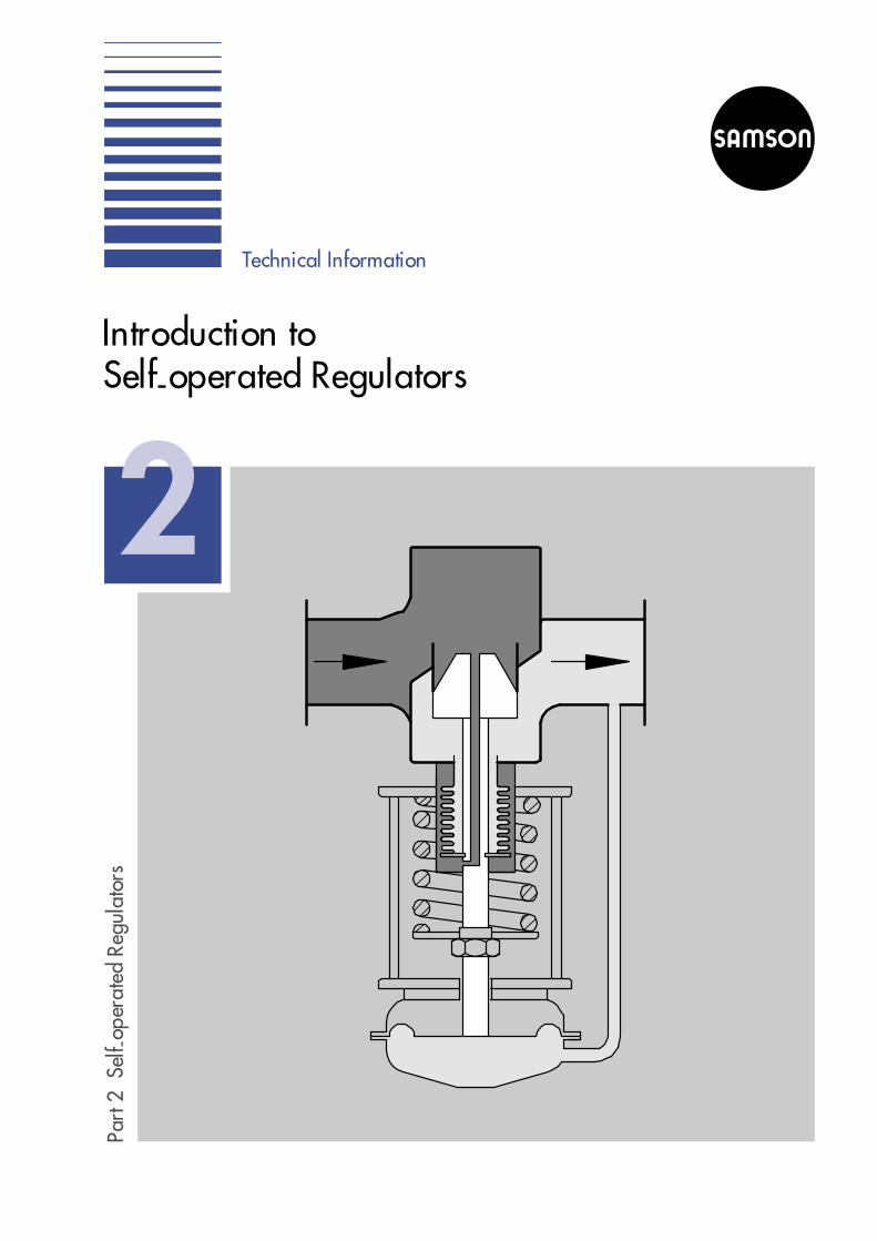
Introduction toSelf-operated Regulators
Technical Information
2

Part 1: Fundamentals
Part 2: Self-operated Regulators
Part 3: Control Valves
Part 4: Communication
Part 5: Building Automation
Part 6: Process Automation
Should you have any further questions or suggestions, pleasedo not hesitate to contact us:
SAMSON AG Phone (+49 69) 4 00 94 67V74 / Schulung Telefax (+49 69) 4 00 97 16Weismüllerstraße 3 E-Mail: [email protected] Frankfurt Internet: http://www.samson.de
Technical Information
Introduction to Self-operatedRegulators
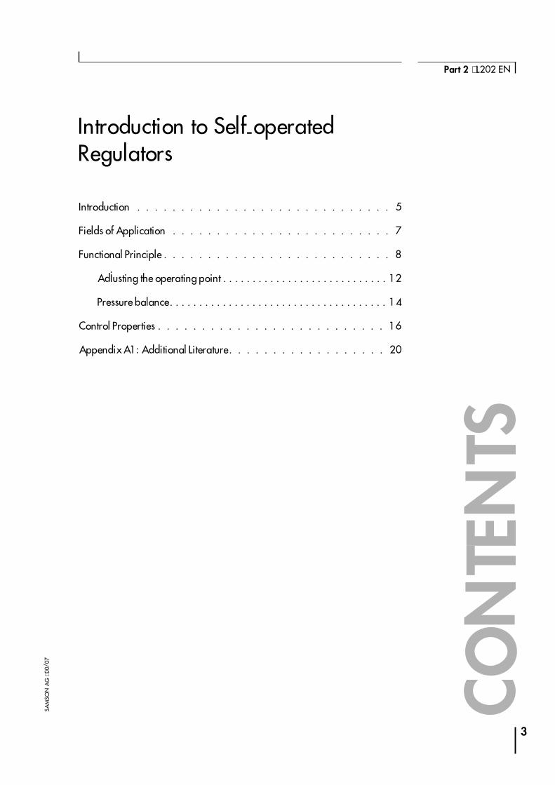
Introduction . . . . . . . . . . . . . . . . . . . . . . . . . . . . . 5
Fields of Application . . . . . . . . . . . . . . . . . . . . . . . . . 7
Functional Principle . . . . . . . . . . . . . . . . . . . . . . . . . . 8
Adjusting the operating point . . . . . . . . . . . . . . . . . . . . . . . . . . . . 12
Pressure balance. . . . . . . . . . . . . . . . . . . . . . . . . . . . . . . . . . . . . 14
Control Properties . . . . . . . . . . . . . . . . . . . . . . . . . . 16
Appendix A1: Additional Literature . . . . . . . . . . . . . . . . . . 20
3
Part 2 ⋅ L202 EN
SAM
SON
AG
⋅00/
07
CON
TEN
TS

4
Self-operated Regulators ⋅ Introduction to Self-operated Regulators
SAM
SON
AG
⋅V74
/H
RB
Introduction
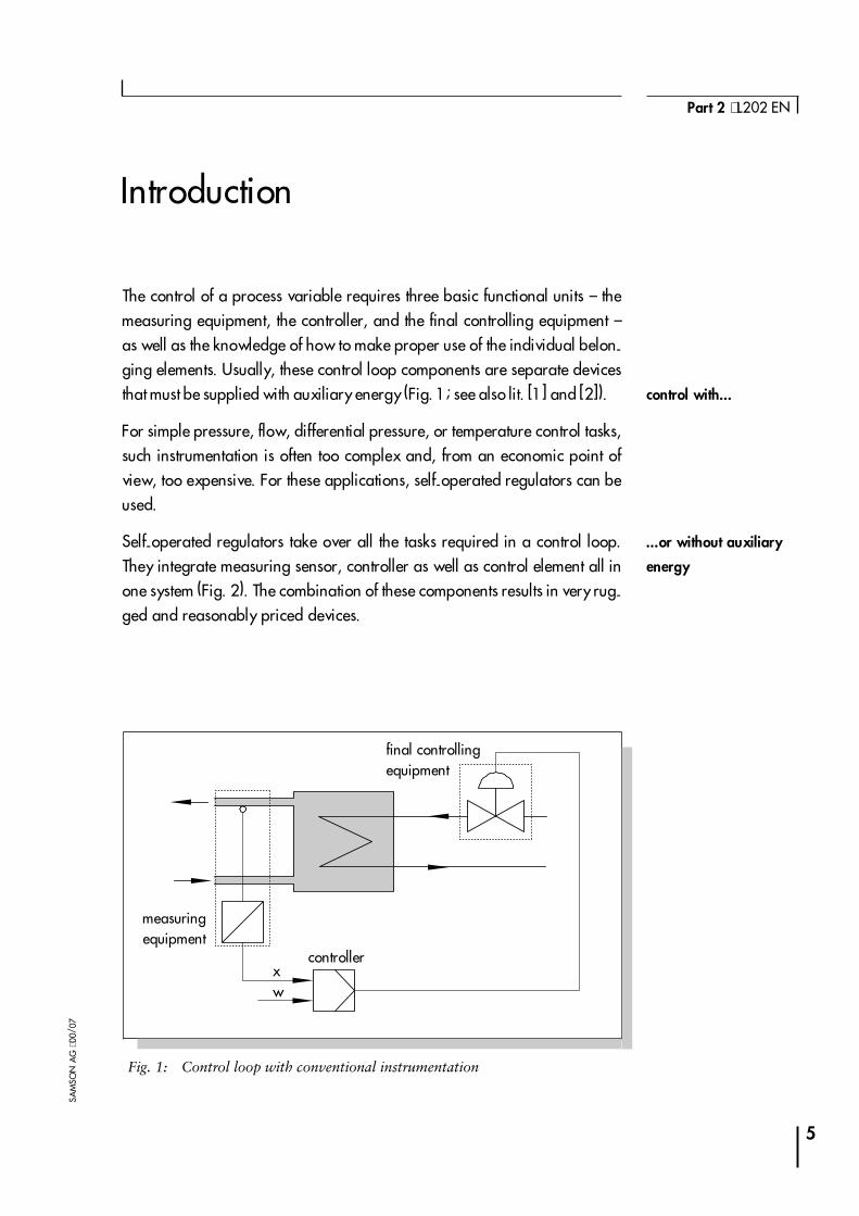
The control of a process variable requires three basic functional units � themeasuring equipment, the controller, and the final controlling equipment �as well as the knowledge of how to make proper use of the individual belon-ging elements. Usually, these control loop components are separate devicesthat must be supplied with auxiliary energy (Fig. 1; see also lit. [1] and [2]).
For simple pressure, flow, differential pressure, or temperature control tasks,such instrumentation is often too complex and, from an economic point ofview, too expensive. For these applications, self-operated regulators can beused.
Self-operated regulators take over all the tasks required in a control loop.They integrate measuring sensor, controller as well as control element all inone system (Fig. 2). The combination of these components results in very rug-ged and reasonably priced devices.
5
Part 2 ⋅ L202 EN
SAM
SON
AG
⋅00/
07
xw
Fig. 1: Control loop with conventional instrumentation
final controllingequipment
measuringequipment
controller
control with...
...or without auxiliary
energy

Since self-operated regulators � as the name indicates � do not require auxi-liary energy from external supply sources, the cost of installation is signifi-cantly lower than for conventional instrumentation.
6
Self-operated Regulators ⋅ Introduction to Self-operated Regulators
SAM
SON
AG
⋅V74
/H
RB
Fig. 2: Control loop with self-operated regulator

Fields of Application
Self-operated regulators are available for temperature, pressure, flow, anddifferential pressure control. They are suitable for all those applications whe-re deviations of the controlled variable from the adjusted set point are ac-ceptable and the set point remains constant over a long time � often duringthe entire useful life.
Self-operated regulators are especially suitable for applications that wouldotherwise require high investment due to the auxiliary energy supply systemadditionally required by other equipment. Therefore, self-operated regula-tors are frequently used in the wide-ranging networks of gas, water and heatsuppliers.
Since self-operated regulators are very reliable in fulfilling their switchingand control functions, even or especially when the energy supply fails, theyare ideally suited as safety equipment. Typetested devices designed accor-ding to the applicable regulations can be used in many fields of applicationand, at the same time, they have a good price/performance ratio comparedto other solutions.
7
Part 2 ⋅ L202 EN
SAM
SON
AG
⋅00/
07
constant set point �
fixed set point control
easy to install
also suitable as safety
equipment

Functional Principle
The performance of work requires energy. Self-operated regulators with-draw this energy from the medium to be controlled.
Using the medium pressure or the thermal properties of the medium (seeFig. 3), the sensor unit of the self-operated regulator builds up a pressurewhich creates the required positioning forces on an actuator diaphragm or aso-called operating element.
Example: pressure reducing valve
In the pressure regulator, the medium pressure p2 acts directly or, if required,via equalizing tank on the rolling diaphragm of the actuator.
8
Self-operated Regulators ⋅ Introduction to Self-operated Regulators
SAM
SON
AG
⋅V74
/H
RB
Fig. 3: Energy supply of control equipment
external process medium
medium pressure
etc.electropneumaticelectrical (analog, digital)pneumatichydraulic
medium temperature� volume change� adsorption principle� vapor pressure principle
with auxiliary energymedium flow
medium density
without auxiliary energy
energysupply
the medium
supplies the energy

Proportional to the diaphragm area AM, a force FM is created which is oppo-sed by the force of a spring FF as well as the flow-related plug force FK (Fig.4):
FK is created due to the pressure difference ∆p = p1 � p2 between the upstre-am and downstream pressure acting on the surface of the plug:
The spring creates reset forces in proportion to the spring range x and enab-les the adjustment of the set point or operating point through preloading:
9
Part 2 ⋅ L202 EN
SAM
SON
AG
⋅00/
07
AS: seat area
FK: force acting on
the plug
FF: spring force
FM: force acting on
the diaphragm
F p A F FM M K F= ⋅ = +2
Fig. 4: Balance of forces in a pressure reducing valve
final balance of forces
p1
p 2AS
AM
p AS1 ⋅
p AS2 ⋅
FK
FF
F p AM M= ⋅2
F p AK S= ⋅∆ AS : seat area
F c xF F= ⋅ cF : spring rate

Assuming an initial state of equilibrium, as illustrated in Fig. 4, any changeof pressure results in a changed balance of forces, thus causing adjustmentsof travel.
This can be clearly seen in the control cycle described in Fig. 5 (next page).
4 If the operating point is in a state of equilibrium, the spring force FF and theforce FK acting on the plug are compensated for by the diaphragm forceFM (phase 1).
4 If the consumption increases, the pressure drop across the valve increasesso that the downstream pressure p2 decreases (phase 2).
4The spring opens the valve against the decreasing diaphragm pressureuntil a balance of forces is reached again with a wider open valve (phase3).
4 In the new valve position (phase 4), the spring force as well as the pressurep2 to be controlled are reduced. A steady-state error (offset) remains witha value that depends on the proportional-action coefficient of the regula-tor.
10
Self-operated Regulators ⋅ Introduction to Self-operated Regulators
SAM
SON
AG
⋅V74
/H
RB
control cycle

11
Part 2 ⋅ L202 EN
SAM
SON
AG
⋅00/
07
1. Balance of forces in the operating point 4Downstream pressure p2
is constant
4Valve remains at steady state
2. Consumption increases (disturbance variable) 4Downstream pressure p2 is falling
4Diaphragm force FM is decreasingand FK increasing
4Result: positioning force FS
4Valve opens
3. Valve opens 4Spring is relieved: spring force FF
is decreasing
4p2 rises: FM is increasing whileFK is decreasing
4Result: FS is decreasing
4Approximation of a new state ofequilibrium
4. Equilibrium with changed valve position Changes compared to phase 1:
4Higher flow rate: valve is openwider
4Spring is further relieved ⇒ p2 islower than at the operating point
4Result: stead-state errror signal(offset)
Fig. 5 Control cycle in self-operated pressure reducing valves
F c xF F= ⋅
F p AM M= ⋅2
F p p AK K= − ⋅( )1 2
FK
FF
F FS = ∑
FM
FK
FF FM
F FS = ∑
FF
FK
FM
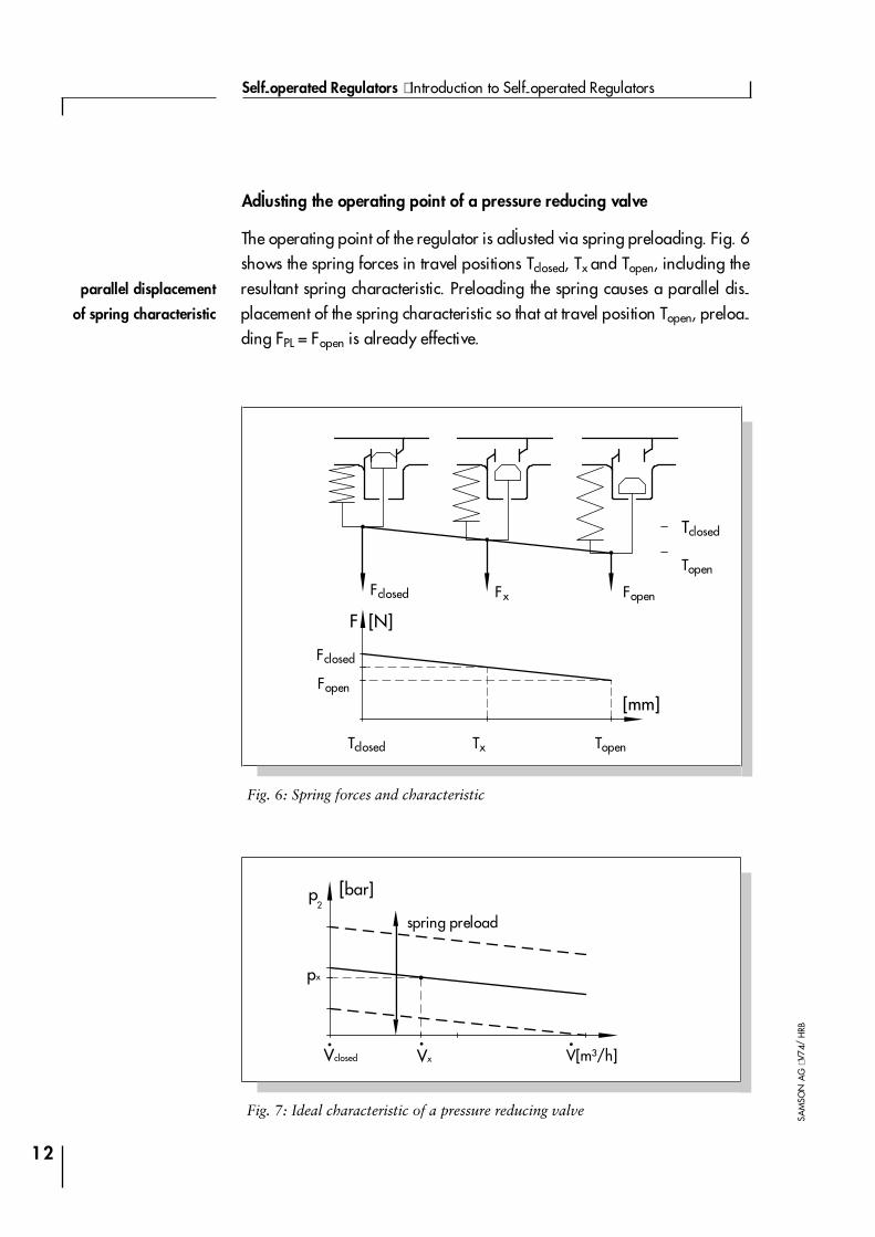
Adjusting the operating point of a pressure reducing valve
The operating point of the regulator is adjusted via spring preloading. Fig. 6shows the spring forces in travel positions Tclosed, Tx and Topen, including theresultant spring characteristic. Preloading the spring causes a parallel dis-placement of the spring characteristic so that at travel position Topen, preloa-ding FPL = Fopen is already effective.
12
Self-operated Regulators ⋅ Introduction to Self-operated Regulators
SAM
SON
AG
⋅V74
/H
RB
F
[mm]
[N]
Fig. 6: Spring forces and characteristic
Vclosed
p
px
[bar]
.Vx
.
2
V[m³/h].
Fig. 7: Ideal characteristic of a pressure reducing valve
Fclosed Fx Fopen
Tclosed Tx Topen
Fclosed
Fopen
Tclosed
Topen
parallel displacement
of spring characteristic
spring preload

While the operating point is adjusted, the spring preloading is increased un-til the process variable to be controlled reaches the required set point value.The spring force adjusted in this manner results from the balance of forces asillustrated in Fig. 4:
With a small AS seat area and low differential pressures, only small FK plugforces are created. Under these conditions, the spring range x which is equi-valent to the valve travel changes in proportion to the pressure p2. The resul-tant manipulated reaction therefore directly depends on the springcharacteristic (see also Fig. 7):
The equation as well as the control characteristic exhibit the pro-portional-action component of this self-operated regulator:
4The factor cF/AM represents the gradient of the characteristic or the pro-portional-action coefficient of the regulator.
4The second summand of the equation (cF ⋅xopen/AM) describes the paralleldisplacement of the characteristic. If high set points are to be adjusted, thisterm must increase. For this, either a version with a stiff spring (high cF)and a small actuator area AM must be chosen, or the spring must be ofgreat length so that it can be sufficiently compressed (xopen will increaseaccordingly).
As previously mentioned, these correlations are only applicable in caseswhere the plug force FK can be neglected. If the seat diameter is large and/orthe differential pressures are high, this method is only permissible when thevalves are equipped with a so-called pressure balancing system. With
13
Part 2 ⋅ L202 EN
SAM
SON
AG
⋅00/
07
F F F c x p A p AF M K F M S= − = ⋅ = ⋅ − ⋅2 ∆
displacement of the
characteristic into the
operating point
adjusting the operating
point
valve travel changes
in proportion to the
pressure
( )pcA
xcA
travel xcA
travelcA
xF
M
F
Mopen
F
M
F
Mopen2 = ⋅ = ⋅ + = ⋅ + ⋅
Xopen: preload

self-operated regulators, such balancing systems are already suited alonedue to the improved control behavior.
Pressure balance
The plug force FK depends on the differential pressure and, therefore, acts asa disturbance variable in the control loop. A high upstream pressure and lar-ge seat diameters create considerable plug forces which the actuator mustovercome, as indicated in the following example:
By applying special structural measures, this disturbance variable can be al-most entirely compensated for.
Fig. 8 shows the version of a valve with a plug balanced by a bellows. Theupstream and downstream pressures additionally act on the plug stem via
14
Self-operated Regulators ⋅ Introduction to Self-operated Regulators
SAM
SON
AG
⋅V74
/H
RB
∆p bar= 10 ; seat ∅ = 125mm F NK = 12 722
Fig. 8: Balance of forces in a pressure reducing valve with plug balancedby a bellows
stationary balance:
forces compensated for atplug and bellows
p AS1 ⋅
p AS2 ⋅
p AB1 ⋅
FF
p A B2 ⋅
FM
p1
p 2
AS
AB
AS: seat area
AB: bellows area
FF: spring forces
(incl. bellows)
FM: force acting on
the diaphragm
differential pressure
acts as disturbance
variable
plug balanced
by a bellows

the bellows area AB, thus creating forces that oppose FK. If the effective areasizes of AS and AB are identical, and if the cross-sectional area of the plugstem is neglected, FK is compensated for by the forces acting on the bellows.
Pressure balanced valves require clearly smaller actuator forces than unba-lanced valves (compare Figs. 4 and 8). When calculating the spring resetforce FF that must be overcome, the elasticity of the bellows must be additio-nally accounted for:
Valves with balanced plugs are used for applications requiring that the con-trol process be as accurate as possible. Balancing systems are always requi-red when high differential pressures are created across the valve, especiallywith large nominal sizes, which then also necessitates high positioning for-ces. These cannot be issued by the actuator anymore without much bigger di-aphragms.
15
Part 2 ⋅ L202 EN
SAM
SON
AG
⋅00/
07
( )F F c c travel FF M F bellows open= = + ⋅ + Fopen: spring preloading
spring reset force

Control Properties
Self-operated regulators are usually designed as proportional controllers.The control behavior of a P controller is essentially determined by the propor-tional-action coefficient (former term: proportional band) as well as by theadjusted operating point.
To describe the correlations as application oriented and clear as possible,the following explanation is based on the example of the pressure reducingvalve, as in the chapters above. With respect to control engineering, thesestatements are applicable to any other self-operated regulator with propor-tional control action.
The fundamentals of control engineering (see lit. [2], for instance) teach usthat if steady-state errors are to be kept as small as possible, a proportio-nal-action coefficient as high as possible (or a small proportional band) is re-quired. In the vicinity of an operating point, KP is calculated from themanipulated variable y and the error e:
In pressure reducing valves, it must therefore be achieved that small pressurechanges create great travel adjustments which in turn create great Kv valuechanges:
4Large travel adjustments are created if the spring stiffness cF is as small aspossible and the actuator diaphragm area AM is large.
4The change of the KV value is related to the contour of the plug and the KVS
value. At the same travel, if the gradient of the control characteristic is highand/or the KVS value is high, the KV value changes are bigger than with aflat characteristic and/or small KVS value.
If the valve is sized for a high proportional-action coefficient, i.e. small sys-tem deviation, the following equipment is required:
16
Self-operated Regulators ⋅ Introduction to Self-operated Regulators
SAM
SON
AG
⋅V74
/H
RB
example of pressure
reducing valve
proportional-action
coefficient
KyeP = ; for pressure reducing valves: K K
pPv= ∆
∆ 2

4soft spring, large actuator area, and high KVS value, i.e. oversized in thiscase, or combinations of these. Proportional-action coefficients that aretoo high, especially in combination with an oversized KVS value, increasethe control loop�s tendency to oscillate.
With respect to spring and actuator these requirements are best met by aself-operated regulator with the lowest set point range.
Example: For a set point of 1.0 bar, therefore, a set point range of 0.2 to1.2 bar must be selected, and not the version ranging from 0.8 to 2.5 bar.
Note: As described on page 13, the following equipment is required to reachhigh set point values:
4stiff spring or small actuator area or long spring ranges and combinationsof these.
If the required device shall exhibit high set point values/positioning forceswhile system deviations are to remain small, contradictory requirements mustbe fulfilled in the sizing of spring and actuator area. There are only these so-lutions to this problem:
4Realization of small system deviations via high KVS values.
4Compensation for high positioning forces via soft, though sufficiently longsprings.
4Using large actuator areas.
All possibilities are restricted in their application. While extremely longsprings result in complex and expensive units with large dimensions, the useof an oversized KVS value is restricted due to physical limitations: during po-sitioning, the actuator must overcome the static and the sliding friction whichis created along the guide and seal of the plug and actuator stem. If thesefrictional forces as well as the additional forces required to close the valveare taken into consideration, the result is the actual manipulated reaction asillustrated in Fig. 9, and not the ideal characteristic shown in Fig. 7.
17
Part 2 ⋅ L202 EN
SAM
SON
AG
⋅00/
07
requirements for small
system deviation
requirements for high
set point values
small system deviation
and high set point
values

The hysteresis Xh created by the static friction limits the control accuracy thatcan be reached. This error cannot be compensated for by using a higher KVS
value to increase KP. Although this would reduce the stationary system devia-tion Xw, the hysteresis in the control characteristic will remain (Fig. 10).
Therefore, an oversized KVS value involves the risk that the system begins tooscillate: on the one hand, the accurate adjustment of the Kv value will beco-
18
Self-operated Regulators ⋅ Introduction to Self-operated Regulators
SAM
SON
AG
⋅V74
/H
RB
Xw1: system deviation
with KP1
Xw2: system deviation
with KP2
Xs
Xp Xw
Xh
V[m³/h].
p2 [%]pmax
Fig. 9: Characteristic of a pressure reducing valve
Xw: system deviation
Xp: proportional band
Xh: hysteresis
XS: closing pressure
p2: downstream
pressure
V.: flow rate
closed
open
Xw2Xw1
V[m³/h].
p2 [%]pmax
Fig. 10: System deviation with different proportional-action coefficients
K KP P1 2<
hysteresis limits
the control accuracy

me more difficult due to the hysteresis; on the other hand, already small sys-tem deviations will then result in extremely big KV value changes.
Due to the described correlations and when control demands are high, it willalways be desirable to reduce the effects of varying ∆p values at the plug asmuch as possible, especially in the case of large nominal sizes, by usingpressure balancing systems and, at the same time, selecting the version withthe smallest set point range.
By following these sizing principles � balancing bellows, soft springs, largeactuator diaphragm and, if required, high KVS values � the system deviationin self-operated regulators can be kept to a minimum. However, proportio-nal-action coefficients that are too high, especially when realized in combi-nation with oversized KVS values, involve the risk that the control loop starts tooscillate. The damping of the measured pressure signal through restrictionsin the control lines to the diaphragm actuator also has its limits.
The described correlations clearly show that the system deviation inself-operated regulators strongly depends on the respective design. The sys-tem deviation in self-operated regulators can therefore be significantly redu-ced by the appropriate measures.
19
Part 2 ⋅ L202 EN
SAM
SON
AG
⋅00/
07
reduction of
positioning forces

Appendix A1:Additional Literature
[1] Terminology and Symbols in Control EngineeringTechnical Information L101 EN; SAMSON AG
[2] Controllers and Controlled SystemsTechnical Information L102 EN; SAMSON AG
[3] Temperature RegulatorsTechnical Information L205 EN; SAMSON AG
[4] Regelungstechnik in der VersorgungstechnikVerlag C.F. Müller GmbH, Karlsruhe
20
Self-operated Regulators ⋅ Introduction to Self-operated Regulators
SAM
SON
AG
⋅V74
/H
RB
APP
ENDI
X

Figures
Fig. 1: Control loop with conventional instrumentation . . . . . . . . . 5
Fig. 2: Control loop with self-operated regulator . . . . . . . . . . . 6
Fig. 3: Energy supply of control equipment . . . . . . . . . . . . . . 8
Fig. 4: Balance of forces in a pressure reducing valve . . . . . . . . . 9
Fig. 5 Control cycle in self-operated pressure reducing valves . . . . 11
Fig. 6: Spring forces and characteristic . . . . . . . . . . . . . . . 12
Fig. 7: Ideal characteristic of a pressure reducing valve. . . . . . . . 12
Fig. 8: Balance of forces in a pressure reducing valve with plug balancedby a bellows . . . . . . . . . . . . . . . . . . . . . . . . 14
Fig. 9: Characteristic of a pressure reducing valve . . . . . . . . . . 18
Fig. 10: System deviation with different proportional-action coefficients. 18
21
Part 2 ⋅ L202 EN
SAM
SON
AG
⋅00/
07
FIG
URE
S
22
Self-operated Regulators ⋅ Introduction to Self-operated Regulators
SAM
SON
AG
⋅V74
/H
RB
NO
TES

SAMSON right on quality course
Our quality assurance system,
approved by BVQi, guarantees a high
quality of products and services.

SAMSON AG ⋅ MESS- UND REGELTECHNIK ⋅ Weismüllerstraße 3 ⋅ D-60314 Frankfurt am MainPhone (+49 69) 4 00 90 ⋅ Telefax (+49 69) 4 00 95 07 ⋅ Internet: http://www.samson.de
2000
/07
⋅L20
2EN


![VALVOLE E STRUMENTAZIONE - Powerflo Solutions Catalogue_E[1].pdf · valvole e strumentazione regolatori di pressione autoazionati a molla spring self operated pressure regulators](https://static.fdocuments.net/doc/165x107/5c69cc6e09d3f27a7e8baeb9/valvole-e-strumentazione-powerflo-cataloguee1pdf-valvole-e-strumentazione.jpg)