
Self-operated Pressure Regulators Type 2404-2 Excess ...€“ NPS 8 and 10 (DN 200 and 250 ... As a...
8
Data Sheet T 2540 EN Associated Information Sheet u T 2500 Edition November 2016 Type 2406 functioning as a pilot valve ½ NPT female thread, C V 1.2 (K VS 1) Type 2441 Input Pressure Regulator ½ NPT female thread, C V 1.2 (K VS 1) Mounting kit M2404-2, consisting of: Hook-up, needle valve etc. Special versions Version with FDA-compliant materials for the food process- ing and pharmaceutical industries · Versions for sour gas service (NACE) · Actuator of pilot valve with seal and leak- age line connection (e.g. for flammable gases) The pilot-operated Type 2404-2 Excess Pressure Valve is pref- erably used for the precise control of inert gas in tank blanket- ing applications. It regulates the excess pressure of the inert gas to a constant pressure within the millibar range. The inert gas (usually nitrogen) is applied to protect the prod- uct inside the tank from reacting with the ambient atmosphere. In this way, the safe operation of tanks is achieved by allow- ing the tank to “breathe” in a controlled manner. Additional benefits include reduced pollution and inert gas costs. The pressure regulator ensures that the blanketing pressure in the tank remains constant while the tank is being filled. Fur- thermore, adverse weather conditions, e.g. direct sunlight, can affect the pressure inside the tank. In this case, the excess pressure valve equalizes the tank pressure, resulting in stable pressure conditions. Special features – Low-maintenance proportional regulator – Pilot control provides excellent control accuracy – Internal set point springs – Soft-seat plug provides bubble-tight shut-off performance – Meets strict emission requirements (TA Luft) – Suitable for sour gas service (NACE) Versions The Type 2404-2 Excess Pressure Valve is a pilot-operated regulator. It consists of the following components: Type 2406 functioning as the main valve NPS 2½ to 6 (DN 65 to 150), balanced by a diaphragm or Type 2422 functioning as the main valve NPS 8 to 16 (DN 200 to 400), balanced by a diaphragm, with Type 2420 Actuator – NPS 8 and 10 (DN 200 and 250): 320 cm² – NPS 12 and 16 (DN 300 and 400): 640 cm² Application Excess pressure valve for set points from 0.075 to 3 psi (5 to 200 mbar) · Valve size NPS 2½ to 16 (DN 65 to 400) Class 150 to 300 (PN 16 to 40) · Suitable for gases at tem- peratures from –5 to 195 °F (–20 to +90 °C) Self-operated Pressure Regulators Type 2404-2 Excess Pressure Valve with Pilot Valve for small set point ranges Fig. 1: Type 2404-2 Excess Pressure Valve, NPS 16
Transcript of Self-operated Pressure Regulators Type 2404-2 Excess ...€“ NPS 8 and 10 (DN 200 and 250 ... As a...
Data Sheet T 2540 EN
Associated Information Sheet u T 2500 Edition November 2016
Type 2406 functioning as a pilot valve½ NPT female thread, CV 1.2 (KVS 1)
Type 2441 Input Pressure Regulator½ NPT female thread, CV 1.2 (KVS 1)
Mounting kit M2404-2, consisting of:Hook-up, needle valve etc.
Special versionsVersion with FDA-compliant materials for the food process-ing and pharmaceutical industries · Versions for sour gas service (NACE) · Actuator of pilot valve with seal and leak-age line connection (e.g. for flammable gases)
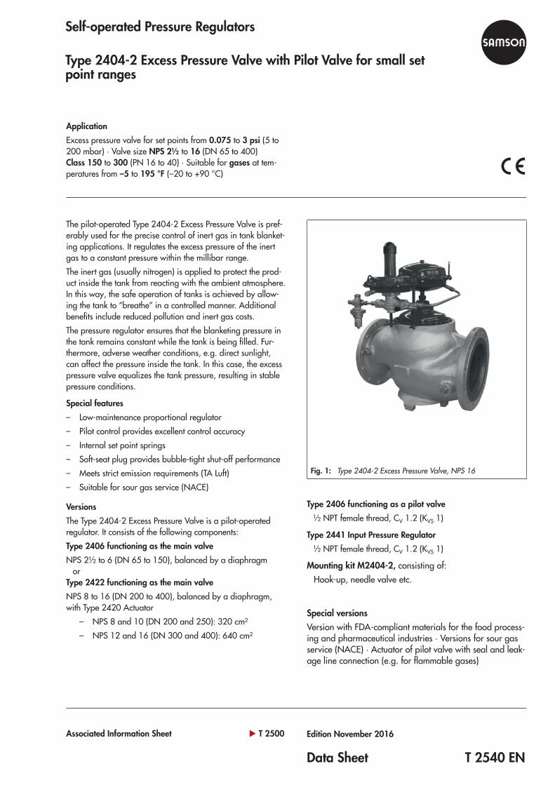
The pilot-operated Type 2404-2 Excess Pressure Valve is pref-erably used for the precise control of inert gas in tank blanket-ing applications. It regulates the excess pressure of the inert gas to a constant pressure within the millibar range.The inert gas (usually nitrogen) is applied to protect the prod-uct inside the tank from reacting with the ambient atmosphere. In this way, the safe operation of tanks is achieved by allow-ing the tank to “breathe” in a controlled manner. Additional benefits include reduced pollution and inert gas costs.The pressure regulator ensures that the blanketing pressure in the tank remains constant while the tank is being filled. Fur-thermore, adverse weather conditions, e.g. direct sunlight, can affect the pressure inside the tank. In this case, the excess pressure valve equalizes the tank pressure, resulting in stable pressure conditions.
Special features – Low-maintenance proportional regulator – Pilot control provides excellent control accuracy – Internal set point springs – Soft-seat plug provides bubble-tight shut-off performance – Meets strict emission requirements (TA Luft) – Suitable for sour gas service (NACE)
VersionsThe Type 2404-2 Excess Pressure Valve is a pilot-operated regulator. It consists of the following components:Type 2406 functioning as the main valveNPS 2½ to 6 (DN 65 to 150), balanced by a diaphragm
orType 2422 functioning as the main valveNPS 8 to 16 (DN 200 to 400), balanced by a diaphragm, with Type 2420 Actuator
– NPS 8 and 10 (DN 200 and 250): 320 cm² – NPS 12 and 16 (DN 300 and 400): 640 cm²
ApplicationExcess pressure valve for set points from 0.075 to 3 psi (5 to 200 mbar) · Valve size NPS 2½ to 16 (DN 65 to 400) Class 150 to 300 (PN 16 to 40) · Suitable for gases at tem-peratures from –5 to 195 °F (–20 to +90 °C)
Self-operated Pressure Regulators
Type 2404-2 Excess Pressure Valve with Pilot Valve for small set point ranges
Fig. 1: Type 2404-2 Excess Pressure Valve, NPS 16

2 T 2540 EN
Principle of operationThe Type 2404-2 Excess Pressure Valve is a pilot-operated regulator. It regulates the pressure of the inert gas upstream of the regulator within a very narrow mbar or psi range to a low pressure by opening when the pressure reaches the adjusted set point. This ensures that the blanketing gas (inert gas) is kept at a constant pressure level in the tank.The following components interact to regulate the pressure of the inert gas.The input pressure regulator (3) is delivered ready-adjusted. It reduces the supply pressure 1) p to the input pressure pe for the pilot valve (2) to approx. 1 bar (positive pressure), ensur-ing precise pressure control even at varying upstream pres-sures.The pilot valve (2) compares the actual pressure with the set point pressure. In the idle state, the pilot valve is closed by the force of the set point spring (2.1).
The upstream pressure p1 to be controlled is routed to the pilot valve over the control line (2.4). The force of the upstream pressure p1 at the operating diaphragm (2.2) is compared with the adjusted spring force of the set point spring. The pilot valve opens when the blanketing gas pressure in the tank rises above the adjusted set point. This causes the control pressure pS to increase as well. The main valve also starts to open when the force of the control pressure pS acting on the actua-tor diaphragm (1.2) in the main valve (1) is greater than the force of the closing spring (1.1). As a result, the blanketing gas is vented to the atmosphere or recovered for processing until the tank blanketing is re-stabilized or the pressure falls below adjusted set point.The needle valve (4) is delivered ready-adjusted and lead-sealed.
__1) Medium for supply pressure p: compressed air or inert gas
Fig. 2: Functional diagram of Type 2404-2 · Version with main valve NPS 2½ to 6 (DN 65 to 150)
Main valve
Pilot valve
1 Main valve1.1 Closing spring1.2 Operating diaphragm (main valve)2 Pilot valve2.1 Set point springs2.2 Operating diaphragm (pilot valve)
2.3 Set point adjuster (screw SW 27/11/8“)
2.4 Control line3 Input pressure regulator (fixed setting)4 Needle valve (lead-sealed setting)p Supply pressure
p1 Upstream pressure (blanketing gas pressure)
p2 Downstream pressurepS Control pressurepe Input pressure (pilot valve)
2.2
2.3
1
p2
pS
p1
p1
pe
p
2.1
2
3
4
1.1
1.2
2.4
Input pressure regulator
Needle valve (lead-sealed setting)
To atmosphere or recovered for processing
Inert gas
Tank

T 2540 EN 3
Technical dataTable 1: Main valve
Type 2406 as main valve, balanced by a diaphragm
Nominal size NPS 2½ DN 65
NPS 3 DN 80
NPS 4 DN 100
– DN 125
NPS 6 DN 150
Pressure rating Class 150, 300 · PN 16, 40CV coefficients KVS coefficients
60 50
94 80
145 125
450 380
Set point ranges 0.07 to 0.2 psi · 0.15 to 0.4 psi · 0.3 to 0.9 psi · 0.7 to 3 psi 5 to 15 mbar · 10 to 30 mbar · 25 to 60 mbar · 50 to 200 mbar
Actuator area 50 in² · 320 cm²Leakage class according to ANSI/FCI 70-2 or IEC 60534-4 Soft-seated, minimum Class IV
Permissible differential pressure Δp 175 psi · 12 barPerm. temperature –5 to +195 °F · –20 to +90 °C 1)
Compliance ·
Type 2422 as main valve, balanced by a diaphragm, with Type 2420 Actuator
Valve size NPS 8 DN 200
NPS 10 DN 250
NPS 12 DN 300
NPS 16 DN 400
Pressure rating Class 150, 300 2) · PN 16, 40CV coefficients KVS coefficients
760 650
930 800
1440 1250
2400 2000
Set point ranges 0.075 to 0.2 psi · 0.15 to 0.45 psi · 0.35 to 0.9 psi · 0.75 to 3 psi 5 to 15 mbar · 10 to 30 mbar · 25 to 60 mbar · 50 to 200 mbar
Actuator area of Type 2420 320 cm² 640 cm²Leakage class according to ANSI/FCI 70-2 or IEC 60534-4 Soft-seated, minimum Class IV
Permissible differential pressure Δp 145 psi · 10 barPerm. temperature –5 to +195 psi · –20 to +90 °C 1)
Compliance · 1) Max. 175 °F/80 °C for EPDM and NBR versions2) NPS 12 and 16: Class 150 (PN 16) only
Table 2: Pilot valveType 2406 functioning as a pilot valveConnection ½ NPT female threadNominal pressure Class 300CV coefficient KVS coefficient
1.2 1
Set point ranges 0.075 to 0.2 psi 5 to 15 mbar
0.15 to 0.45 psi 10 to 30 mbar
0.35 to 0.9 psi 25 to 60 mbar
0.75 to 3 psi 50 to 200 mbar
Actuator area 100 in² · 640 cm² 50 in² · 320 cm² 50 in² · 320 cm² 50 in² · 320 cm²Input pressure pe Fixed setting by input pressure regulator, min. 15 psi ∙ min. 1 barPerm. temperature –5 to +195 °F ∙ –20 to +90 °C 1)
1) Max. 175 °F/80 °C for EPDM and NBR versions
Table 3: Materials · Material numbers according to ASTM and DIN ENType 2422 functioning as the main valveBody A126B, A216 WCC, A351 CF8M · EN-JL1040, 1.0619, 1.4408Valve seat and plug NPS 6 to 10 (DN 150 to 250): CF3M (1.4409)
NPS 12 and 16 (DN 300 and 400): 304 or 410 (1.4301) 1)
Plug seal EPDM · NBR · FKMOperating diaphragm, balancing diaphragm EPDM · NBR · FKM 2)
Internal parts, guiding parts 316LDiaphragm cases 1.0332 (1.4301/stainless steel body)Actuator springs 1.4310 3)
1) NPS 12 and 16 (DN 300 and 400): optionally 1.4404/316L2) NPS 8, 10 and 12 (DN 200, 250 and 300) only3) Versions for sour gas service (NACE): Hastelloy

4 T 2540 EN
Type 2406 functioning as the main valve
Body A126B, A216 WCC, A351 CF8M · EN-JL1040, 1.0619, 1.4408
Valve seat 316L
Plug 316L
Plug seal EPDM · NBR · FKM
Operating diaphragm, balancing diaphragm EPDM · NBR 1) · FKM
Internal parts, guiding parts 316L
Diaphragm cases 1.0332 (1.4301/stainless steel body)
Actuator springs 1.4310 2)
1) Not for NPS 2½, 3, and 4 (DN 65, 80, and 100)2) Versions for sour gas service (NACE): Hastelloy®
Type 2406 functioning as a pilot valve
Pilot valve Type 2406 1)
Body A216 WCC 2)
Valve seat 316L
Plug 316L
Plug seal EPDM · NBR · FKM
Operating diaphragm EPDM · FKM
Internal parts, guiding parts 316L
Set point spring 1.4310
Mounting kit
Piping Stainless steel
NPT screw fittings 316L
Needle valve, input pressure regulator 316L
1) Versions for sour gas service (NACE) possible2) A351 CF8M on request
Dimensions · NPS 2½ to 6 (DN 65 to 150)
Table 4: Dimensions · NPS 2½ to 6/DN 65 to 150 (see Fig. 3)
Type 2404-2 NPS 2½ DN 65
NPS 3 DN 80
NPS 4 DN 100
– DN 125
NPS 6 DN 150
L1Class 150 10.9”/276 mm 11.7”/298 mm 13.9”/352 mm – 17.75”/451 mm
Class 300 11.5”/292 mm 12.5”/318 mm 14.5”/368 mm – 18.6”/473 mm
L1 PN 16 and 40 11.4”/290 mm 12.2”/310 mm 13.8”/350 mm 15.75”/400 mm 18.9”/480 mm
L2 (approx.) 14.2”/360 mm 12.5“/317 mm
L3 (approx.) 9.4“/240 mm 8.3“/212 mm
ØD
5 to 15 mbar 0.075 to 0.2 psi Ø15“/380 mm, A = 100 in²/640 cm²
10 to 30 mbar 0.15 to 0.45 psi Ø11.2“/285 mm, A = 50 in²/320 cm²
25 to 60 mbar 0.35 to 1.5 psi Ø11.2“/285 mm, A = 50 in²/320 cm²
50 to 200 mbar 0.75 to 3 psi 11.2“/285 mm
H 24.6“/625 mm 25“/635 mm 26“/660 mm 28.2“/715 mm 29.1“/740 mm
H3 3.8“/98 mm 3.9“/100 mm 4.7“/120 mm 5.7“/145 mm 6.9“/175 mm
B (approx.) 9.9“/250 mm
Weight, approx. 123 lb/56 kg 135 lb/61 kg 154 lb/70 kg 280 lb/127 kg 291 lb/132 kg

T 2540 EN 5
Fig. 3: Dimensions · NPS 2½ to 6 (DN 65 to 150)
ØD
H
H3
B
L3
L1
L2
Pipe Ø ½“ Supply pressure p
Pipe Ø ½“ Control line for upstream pressure p1
Pipe Ø ½“ Supply pressure p

6 T 2540 EN
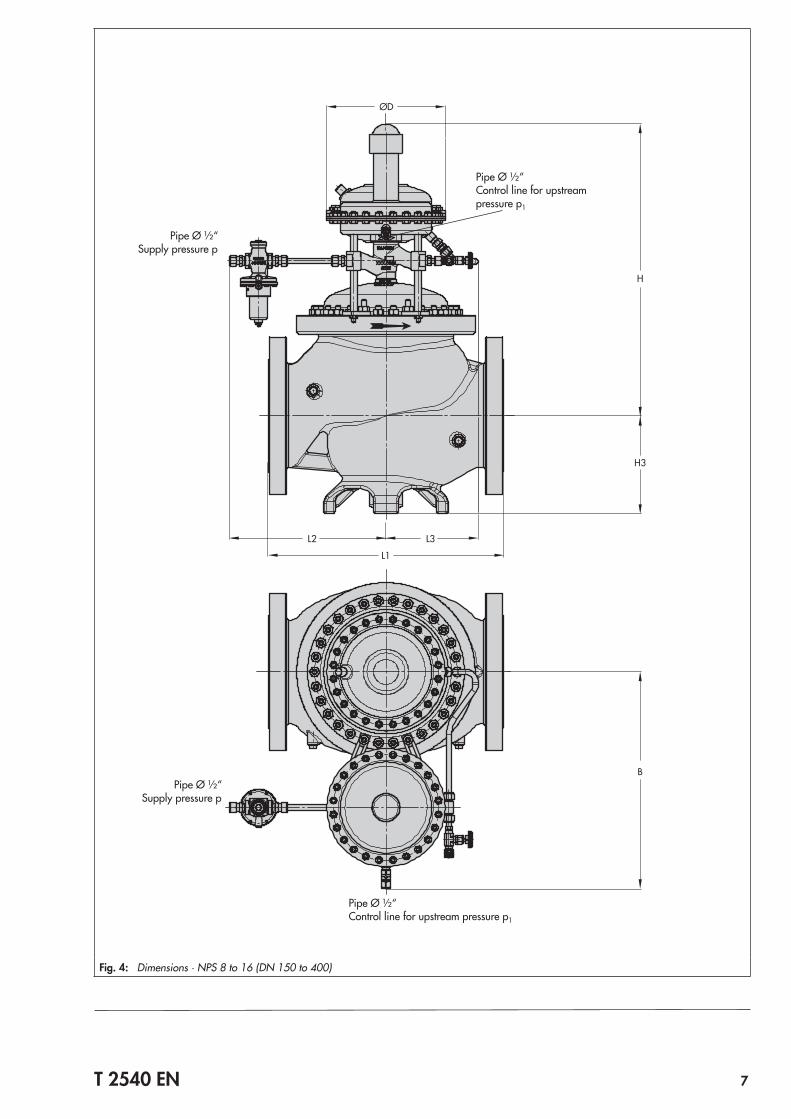
Dimensions · NPS 8 to 16 (DN 200 to 400)
Table 5: Dimensions · NPS 8 to 16/DN 150 to 400 (see Fig. 4)
Type 2404-2 NPS 8 DN 200
NPS 10 DN 250
NPS 12 DN 300
NPS 16 DN 400
L1Class 150 21.4”/543 mm 26.5“/673 mm 28.9“/736 mm 40“/1016 mm
Class 300 22.4”/568 mm 27.9“/708 mm – –
L1 PN 16 and 40 18.9”/480 mm 23.6“/600 mm 28.7“/730 mm 33.5“/850 mm
L2 (approx.) 14.9“/378 mm 19.7“/500 mm
L3 (approx.) 8.2“/208 mm 12.3“/313 mm 13.5“/343 mm
ØD
5 to 15 mbar 0.075 to 0.2 psi Ø15“/380 mm, A = 100 in²/640 cm²
10 to 30 mbar 0.15 to 0.45 psi Ø11.2“/285 mm, A = 50 in²/320 cm²
25 to 60 mbar 0.35 to 1.5 psi Ø11.2“/285 mm, A = 50 in²/320 cm²
50 to 200 mbar 0.75 to 3 psi Ø11.2“/285 mm, A = 50 in²/320 cm²
H 27.2“/690 mm 28“/710 mm 28.7“/730 mm 29.5“/750 mm
H3 9.3“/235 mm 10.2“/260 mm 11.2“/285 mm 14.6“/370 mm
B (approx.)
50 in²/320 cm² 19.5“/495 mm 20.7“/525 mm 22.3“/567 mm 25.2“/641 mm
100 in²/640 cm² 21.3“/542 mm 22.6“/573 mm 23.8“/605 mm 25.9“/658 mm
Weight, approx. 529 lb/240 kg 573 lb/260 kg 772 lb/350 kg 1477 lb/670 kg
T 2540 EN 7
Fig. 4: Dimensions · NPS 8 to 16 (DN 150 to 400)
ØD
H
H3
B
L3
L1
L2
Pipe Ø ½“ Supply pressure p
Pipe Ø ½“ Control line for upstream pressure p1
Pipe Ø ½“ Supply pressure p
Pipe Ø ½“ Control line for upstream pressure p1

Specifications subject to change without notice
SAMSON AG · MESS- UND REGELTECHNIK Weismüllerstraße 3 · 60314 Frankfurt am Main, Germany Phone: +49 69 4009-0 · Fax: +49 69 4009-1507 [email protected] · www.samson.de T 2540 EN 20
17-1
1-14
· En
glish
Installation
The regulator is delivered as a ready-to-install unit. – Install the main valve in the pipeline
at the site of installation and connect the control line (inert gas pressure p1) to the pilot valve (pipe Ø ½“).
– Connect the line for the supply pressure p to the input pressure regulator (pipe Ø ½“).
Install the regulator in such a way that it is still easily accessib-le after the plant is completed to facilitate maintenance or re-vision work. Allow enough space for set point adjustment at the pilot valve using a socket wrench.The following points must be observed: – Installation in horizontal pipelines – Install the valve assembly with the pilot valve pointing up – Direction of flow must correspond with the arrow on the
body of the main valveRefer to u EB 2540 for further details.
Ordering textType 2404-2 Excess Pressure ValveType 2406 or Type 2422 Valve as main valveValve body material ...Material: diaphragm ..., plug seal ...NPS (DN) ..., CV (KVS) coefficient ...Type 2406 functioning as a pilot valveSet point range 0.075 to 0.2 psi · 0.15 to 0.45 psi · 0.35 to 0.9 psi · 0.75 to 3 psi (5 to 15 mbar · 10 to 30 mbar · 25 to 60 mbar · 50 to 200 mbar)Type 2441 as input pressure regulator, mounting kit M2404-2