Rocking steel shear walls with energy dissipation devicesdb.nzsee.org.nz/2014/oral/9_Djojo.pdf ·...
9
Paper Number O9 Rocking steel shear walls with energy dissipation devices 2014 NZSEE Conference G.S. Djojo, G.C. Clifton & R.S. Henry Department of Civil and Environmental Engineering, University of Auckland, Auckland. ABSTRACT: Conventional steel panel shear walls (SPSWs) comprise thin steel plates framed by beams and columns. These walls have been developed as ductile systems which resist seismic forces through a combination of shear resistance from the plates and flexural resistance from the frames. The internal shear forces in the plates are resolved into diagonal tension and compression principal stresses and after the compression diagonal buckles, the plates behave effectively as tension cross bracing. The ductile action is achieved through tensile yielding of the web plate and a plastic hinge is formed at the beam ends, with the columns expected to remain elastic. Although this system, under severe earthquakes, dissipates considerable energy through the yielding of selected members, structural damage with residual deformation may make repair difficult. Therefore, an innovative steel panel shear wall is being developed by combining the advantages of the conventional wall system with a centralised rocking mechanism and energy dissipation devices to produce a lateral force resisting system with a low damage design solution that is intended to remain elastic during the rocking and expected to return to original position after an ultimate limit state level earthquakes. During severe earthquakes, the columns move above or below the original position and the energy dissipation devices provide restoring forces to pull back the columns. A rocking base point at the bottom middle of the wall maintains the stability of the structure. This paper presents the concept and numerical analysis of this wall focusing on the energy dissipation device system. 1 INTRODUCTION Conventional steel panel shear walls (SPSWs) comprise thin steel plates (web plates) framed by beams (horizontal boundary elements, HBEs) and columns (vertical boundary elements, VBEs). They possess high initial stiffness and strength, and are capable of development substantial ductility, and significant energy dissipation (Sabelli and Bruneau 2007). Those characteristics make these walls as an attractive solution for buildings in earthquake prone areas. In addition, the walls are suitable for low-rise to high- rise construction and for new or retrofit of existing construction as these walls can be configured as core systems where a structural system requires better torsional and overturning stiffness and capacity which are suited for mid-rise and high-rise buildings or multiple planar systems where a structural system requires more shear capacity rather than overturning moment capacity which are suited for low-rise and retrofitting existing buildings (Seilie and Hooper 2005). By utilising a composite floor system, these walls would offer some benefits such as lesser building weight that would reduce foundation loads and seismic base plate and fast construction that would reduce construction time. However, in general, these wall systems are governed by lateral deformation rather than strength. Therefore, either stiff and strong columns or longer bays of the walls are considered to satisfy drift limit requirement. These walls have been implemented in some buildings in the United States, Canada, Japan, and New Zealand. SPSWs resist lateral shear forces with a combination of shear resistance from the web plates and flexural resistance from the frames. The web plates are expected to resist almost all of the shear forces in the wall by resolving the forces into diagonals resisting tension and compression principal stresses. After the compression diagonal buckles at low level of shear force, the web plates formed tension field
Transcript of Rocking steel shear walls with energy dissipation devicesdb.nzsee.org.nz/2014/oral/9_Djojo.pdf ·...

Paper Number O9
Rocking steel shear walls with energy dissipation devices
2014 NZSEE Conference
G.S. Djojo, G.C. Clifton & R.S. Henry
Department of Civil and Environmental Engineering, University of Auckland, Auckland.
ABSTRACT: Conventional steel panel shear walls (SPSWs) comprise thin steel plates framed by beams and columns. These walls have been developed as ductile systems which resist seismic forces through a combination of shear resistance from the plates and flexural resistance from the frames. The internal shear forces in the plates are resolved into diagonal tension and compression principal stresses and after the compression diagonal buckles, the plates behave effectively as tension cross bracing. The ductile action is achieved through tensile yielding of the web plate and a plastic hinge is formed at the beam ends, with the columns expected to remain elastic. Although this system, under severe earthquakes, dissipates considerable energy through the yielding of selected members, structural damage with residual deformation may make repair difficult. Therefore, an innovative steel panel shear wall is being developed by combining the advantages of the conventional wall system with a centralised rocking mechanism and energy dissipation devices to produce a lateral force resisting system with a low damage design solution that is intended to remain elastic during the rocking and expected to return to original position after an ultimate limit state level earthquakes. During severe earthquakes, the columns move above or below the original position and the energy dissipation devices provide restoring forces to pull back the columns. A rocking base point at the bottom middle of the wall maintains the stability of the structure. This paper presents the concept and numerical analysis of this wall focusing on the energy dissipation device system.
1 INTRODUCTION
Conventional steel panel shear walls (SPSWs) comprise thin steel plates (web plates) framed by beams (horizontal boundary elements, HBEs) and columns (vertical boundary elements, VBEs). They possess high initial stiffness and strength, and are capable of development substantial ductility, and significant energy dissipation (Sabelli and Bruneau 2007). Those characteristics make these walls as an attractive solution for buildings in earthquake prone areas. In addition, the walls are suitable for low-rise to high-rise construction and for new or retrofit of existing construction as these walls can be configured as core systems where a structural system requires better torsional and overturning stiffness and capacity which are suited for mid-rise and high-rise buildings or multiple planar systems where a structural system requires more shear capacity rather than overturning moment capacity which are suited for low-rise and retrofitting existing buildings (Seilie and Hooper 2005). By utilising a composite floor system, these walls would offer some benefits such as lesser building weight that would reduce foundation loads and seismic base plate and fast construction that would reduce construction time. However, in general, these wall systems are governed by lateral deformation rather than strength. Therefore, either stiff and strong columns or longer bays of the walls are considered to satisfy drift limit requirement. These walls have been implemented in some buildings in the United States, Canada, Japan, and New Zealand.
SPSWs resist lateral shear forces with a combination of shear resistance from the web plates and flexural resistance from the frames. The web plates are expected to resist almost all of the shear forces in the wall by resolving the forces into diagonals resisting tension and compression principal stresses. After the compression diagonal buckles at low level of shear force, the web plates formed tension field

2
actions; a series of diagonal folds that behaves effectively as tension cross bracing to carry the shear forces in every floor. The ductile action is achieved through tensile yielding of the web plate and a plastic hinge is formed at the beam ends, with the columns expected to remain elastic. Therefore, beams and columns have to be stiff and strong to anchor the tension field actions under severe earthquakes (Bruneau 2013). However, after such shaking, structural damage with residual deformation in the wall is likely which may require expensive structural repair or demolition.
The innovative SPSW being developed combines the advantages of the conventional wall system with a centralised rocking mechanism and energy dissipation devices. A rocking pivot at the bottom middle of the wall provides the stability of the structure while the columns move above or below the original position so that the wall remains elastic during the rocking. Energy dissipation devices not only dissipate considerable energy to minimise damage to the rest of the structure, but also provide restoring forces to pull the columns back to the original position. Thus, this rocking steel shear wall (RSSW) is expected to return to its original position without significant structural damage and residual deformation following earthquakes. This system is therefore intended to fulfil a low damage design solution.
2 ROCKING STEEL SHEAR WALL
2.1 Design concepts
The rocking wall system (Fig. 1) utilises an elastic tension field action to resist the shear force, a rocking pivot to reduce the impact of uplifting and maintain the stability of the structure, and energy dissipation devices installed at the bottom of the columns to dissipate energy and provide re-centring of the wall. The lateral forces are resolved into shear force and axial force. The shear forces form diagonal tension fields in web plates to be distributed to the nearest boundary frames. These forces are anchored to the end posts of the topmost and bottommost beam and then transferred through the rocking pivot into the foundation system. The axial forces are carried by columns to the foundation system through the energy dissipation devices. These devices are designed to remain elastically rigid up to a defined column axial force. When the applied force is more than that axial force, the devices will dissipate considerable energy during the rocking and will provide the ability to re-centre after earthquakes. The columns and devices are permitted to undertake small arc rotations induced by vertical movements of the columns.
Figure 1. Rocking wall components
Rigid connections (Fig. 2) are used to connect the beams to the columns and the columns to V brace

3
utilising laser cutting technology to create an opening on the columns (Square Hollow Sections). The beams are then slotted into the columns and welded to the columns. Afterward, these columns are filled with concrete to increase the strength and stiffness of the connections. The rigidity of fixed connection is achieved by transferring the moment from the beam to the column as a vertical force couple into the column. The web plates are connected to the boundary frames by using fillet welds.
Figure 2. Beam to column rigid connection
The rocking wall system is designed to resist gravity loads and lateral forces. The load paths are illustrated in Figure 3.
a) Gravity loads b) Seismic loads
Figure 3. Load paths
Under gravity loads, the beams are responsible to carry all gravity loads to the columns and the loads are then transferred into foundation system through both the V brace and columns. Under lateral loads, the system has to meet specific performance requirements (Fig. 4), as follows:
1. Serviceability Limit State earthquake (SLS); the system remains elastic and rigid under SLS earthquakes and ULS wind forces. The tension field actions start to form in the web plates and the forces are distributed to the nearest boundary frames. The SLS event to NZS1170.5 (NZS1170.5 2004) has an 86.5% probability of exceedance in 50 years for buildings of normal importance (IL = 2).
2. Ultimate Limit State earthquake (ULS); when the intensity of the seismic loads is greater than the SLS earthquakes, the tension field actions are fully developed and the system begins to rock. The energy dissipation devices start to dissipate most of the energy in order to keep the wall components elastic. These devices are also responsible to provide self-centring after an earthquake. The ULS event to NZS 1170.5 has a 10% probability of exceedance in 50 years for buildings of normal importance.
3. Maximum Considered Earthquake event (MCE); when the seismic loads exceed the ULS, selected components such as web plates and end posts are expected to yield in tension and flexural respectively. The columns and V brace remain elastic to prevent collapse of the structure. The MCE event to NZS 1170.5 has a 2% probability of exceedance in 50 years for buildings of normal importance.
FiC C
G+Q
T
T C
C
Vbase

4
F0
Kloading
F
Kunloading
a) SLS b) ULS c) Self-centring d) Flag-shaped hysteresis
Figure 4. Rocking response
The design of the wall follows New Zealand Standard (NZS1170.5 2004) where under the SLS earthquakes, the structural ductility factor,μ, is 1.0, Sp = 0.7 and the maximum inter-storey drift is limited to hs/300 or 0/33%. Under the ULS earthquakes, the maximum inter-storey drift shall not exceed 2.5% and the structural ductility factor is μ= 4.0, Sp = 0.7. Under MCE, capacity design is used to prevent collapse of the V brace and columns.
2.2 Numerical model
This concept and system has been used to design a new four-storey building. Two walls are placed on the short direction at each external frame, giving four walls for that direction of loading. The tributary area for the gravity loads and the seismic weight for one wall are 5 meter by 5 meter and 35 meter by 10 meter respectively. The wall (Fig. 5) is analysed using SAP 2000 Ver.15.1.0 with a non-linear analysis case to determine the behaviour of the wall including internal forces and lateral deflections. These internal forces (Fig. 6) are then used to do preliminary design.
Figure 5. Elevation view of a rocking wall
a
b
c
Fi (ULS) Fi (SLS)
4 @ 3.750 m = 15 m
5 m
5
a) Axial forces b) Shear forces c) Bending moments
Figure 6. Analysis Results
In this model, web plates are modelled as shell elements with orthotropic materials. To represent the behaviour of the tension field action, the full modulus of elasticity is assigned to the axis parallel to the tension diagonal direction (axis 1) and the modulus of elasticity on the compression diagonal direction (axis 2) is set according to the elastic critical buckling stress. Also, the in-plane shear modulus and Poisson’s ratio (1-2 direction) are set to zero and the local axis of the shell element is oriented in diagonal direction according to the angle of tension field actions (Rezai et al 2004).
A range of web plate thicknesses, columns, and beams have been developed to obtain an optimum solution based on the lowest overall weight but still satisfying the lateral deflection requirement. Preliminary design and lateral deflections at each storey are given in Table 1 and Table 2.
Table 1. Preliminary design
Members Dimensions (mm) Grade
Web plates 10 300
Beams 310UB40.4 300
End posts 610UB125 300
Columns SHS 400x400x10 -CF 350
V brace 250UC72.9 300
Table 2. Lateral deformations at serviceability limit state
Storey Lateral Deformations (mm) Story Drifts (mm) SLS Limit (0.33%) (mm)
Roof 43.5 11.8 12.5
Storey 3 31.7 8.5 12.5
Storey 2 23.2 12.4 12.5
Storey 1 10.8 10.8 12.5
6
3 ENERGY DISSIPATION DEVICES CONCEPT
3.1 Ringfeder – Friction ring springs
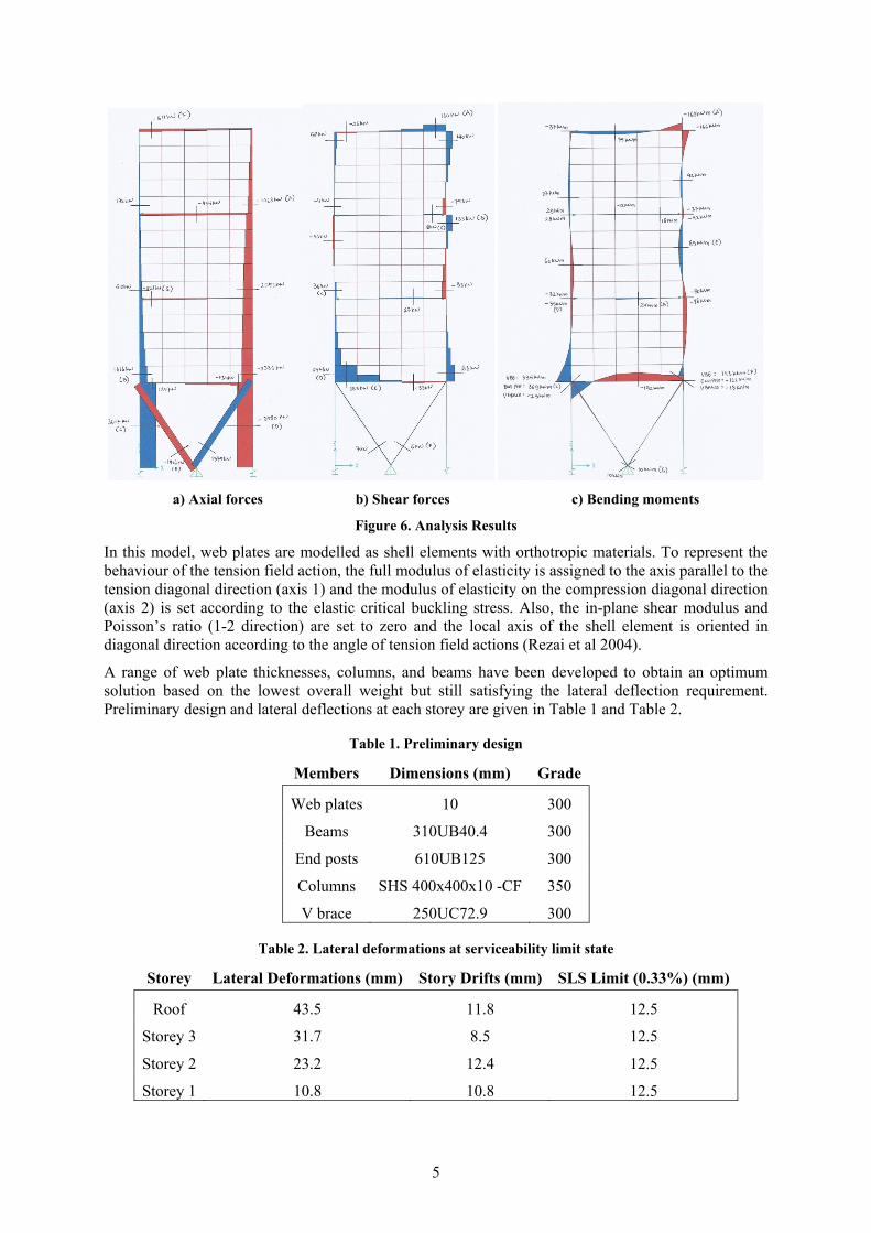
A ring spring (Ringfeder) or a stack of ring springs is a compression spring consisting of inner and outer rings assembled and stacked together. The ring spring provides constant force-displacement relationship and considerable energy absorption and also can be preloaded (Gross 1960). The ring spring is shown in Figure 7.
a) Isometric view b) Exploded view c) Rings arrangement
Figure 7. Ringfeder - ring spring
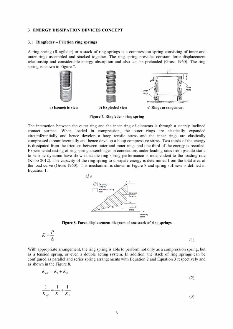
The interaction between the outer ring and the inner ring of elements is through a steeply inclined contact surface. When loaded in compression, the outer rings are elastically expanded circumferentially and hence develop a hoop tensile stress and the inner rings are elastically compressed circumferentially and hence develop a hoop compressive stress. Two thirds of the energy is dissipated from the frictions between outer and inner rings and one third of the energy is recoiled. Experimental testing of ring spring assemblages in connections under loading rates from pseudo-static to seismic dynamic have shown that the ring spring performance is independent to the loading rate (Khoo 2012). The capacity of the ring spring to dissipate energy is determined from the total area of the load curve (Gross 1960). This mechanism is shown in Figure 8 and spring stiffness is defined in Equation 1.
Figure 8. Force-displacement diagram of one stack of ring springs
PK =
Δ (1)
With appropriate arrangement, the ring spring is able to perform not only as a compression spring, but as a tension spring, or even a double acting system. In addition, the stack of ring springs can be configured as parallel and series spring arrangements with Equation 2 and Equation 3 respectively and as shown in the Figure 8.
1 2effK K K= +
(2)
1 2
1 1 1
effK K K= +
(3)
7
a) Parallel arrangement b) Serial arrangement
Figure 9. Ring spring arrangements
3.2 Double acting preloaded ring springs
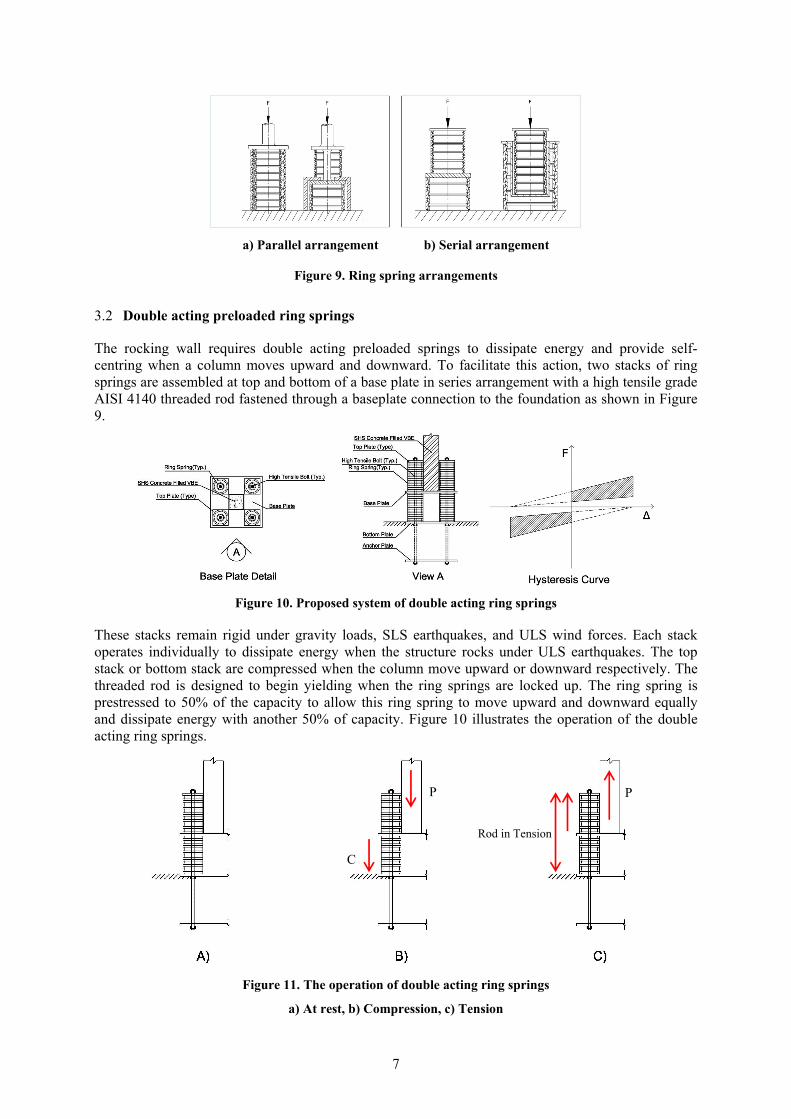
The rocking wall requires double acting preloaded springs to dissipate energy and provide self-centring when a column moves upward and downward. To facilitate this action, two stacks of ring springs are assembled at top and bottom of a base plate in series arrangement with a high tensile grade AISI 4140 threaded rod fastened through a baseplate connection to the foundation as shown in Figure 9.
Figure 10. Proposed system of double acting ring springs
These stacks remain rigid under gravity loads, SLS earthquakes, and ULS wind forces. Each stack operates individually to dissipate energy when the structure rocks under ULS earthquakes. The top stack or bottom stack are compressed when the column move upward or downward respectively. The threaded rod is designed to begin yielding when the ring springs are locked up. The ring spring is prestressed to 50% of the capacity to allow this ring spring to move upward and downward equally and dissipate energy with another 50% of capacity. Figure 10 illustrates the operation of the double acting ring springs.
Figure 11. The operation of double acting ring springs
a) At rest, b) Compression, c) Tension
Rod in Tension
P P
C
8
4 EXPERIMENTAL VALIDATION OF THE DOUBLE ACTING RING SPRING SYSTEM
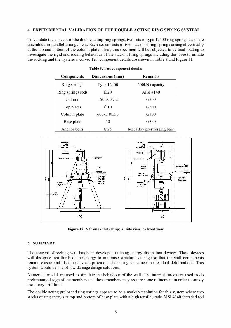
To validate the concept of the double acting ring springs, two sets of type 12400 ring spring stacks are assembled in parallel arrangement. Each set consists of two stacks of ring springs arranged vertically at the top and bottom of the column plate. Then, this specimen will be subjected to vertical loading to investigate the rigid and rocking behaviour of the stacks of ring springs including the force to initiate the rocking and the hysteresis curve. Test component details are shown in Table 3 and Figure 11.
Table 3. Test component details
Components Dimensions (mm) Remarks
Ring springs Type 12400 200kN capacity
Ring springs rods ∅20 AISI 4140
Column 150UC37.2 G300
Top plates ∅10 G300
Column plate 600x240x50 G300
Base plate 50 G350
Anchor bolts ∅25 Macalloy prestressing bars
Figure 12. A frame - test set up; a) side view, b) front view
5 SUMMARY
The concept of rocking wall has been developed utilising energy dissipation devices. These devices will dissipate two thirds of the energy to minimise structural damage so that the wall components remain elastic and also the devices provide self-centring to reduce the residual deformations. This system would be one of low damage design solutions.
Numerical model are used to simulate the behaviour of the wall. The internal forces are used to do preliminary design of the members and these members may require some refinement in order to satisfy the storey drift limit.
The double acting preloaded ring springs appears to be a workable solution for this system where two stacks of ring springs at top and bottom of base plate with a high tensile grade AISI 4140 threaded rod

9
as a turned down rod are assembled to dissipate energy when the columns move upward or downward during the rocking. The ring spring is elastically rigid under gravity loads, SLS earthquakes, and ULS wind forces.
Following the completion of the double acting ring spring experimental testing, component testing of the bottom level collector beam/brace/column sub-assemblage will be undertaken to determine the effective detail for construction of the assemblage in order to meet the system performance criteria described in section 2.1 that will be the topic of a further paper.
6 ACKNOWLEDGEMENTS
The first author would like to acknowledge the support and guidance of his two supervisors, the second and third authors and the financial support of the University of Auckland through his University of Auckland Doctoral Scholarship.
REFERENCES
Bruneau, M. 2013. Self-Centering Steel Plate Shear Walls, Steel Innovations Conference 2013. February 21-22, 2013. New Zealand.
Bruneau, M., Uang, C, & Sabelli, R. 2011. Ductile Design of Steel Structures Second Edition. the United States of America: McGraw-Hill.
CSI 2011. SAP-2000, Structural Analysis Program. the United States of America: Computers and Structures, Inc.
Deierlein, G.G., Krawinkler, H., Ma, X., Eatherton, M., Hajjar, J.F., Takeuchi, T., Kasai. & K. Midorikawa, M. 2011. Earthquake Resilient Steel Braced Frames with Controlled Rocking and Energy Dissipating Fuses. Steel Construction: Design and Research, Vol. 4(3), 171-175.
Djojo, G. S., Clifton, C. & Henry, R.S. 2013. The Concept of an Elastic Rocking Steel Shear Wall, The Pacific Structural Steel Conference 2013. Singapore
Gledhill, S.M., Sidwell, G.K. & Bell, D.K. 2008. The Damage Avoidance Design of Tall Steel Frame Buildings – Fairlie Terrace Student Accommodation Project, Victoria University of Wellington, NZSEE Conference, New Zealand.
Gross, S. 1960. Calculation and Design of Metal Springs. the United Kingdom: Chapman and Hall LTD
Khoo, HH. 2012. Development of the Low Damage Self-Centring Sliding Hinge Joint. PhD Thesis, University of Auckland. New Zealand.
MacRae, G. & Clifton, C. 2013. Low Damage Design of Steel Structures. Steel Innovations 2013 workshop, Christchurch, February 21-22, 2013, New Zealand.
MacRae, G. & Clifton, C. 2013. Rocking Structure Design Considerations. Steel Innovations 2013 workshop, Christchurch, February 21-22, 2013, New Zealand.
New Zealand Standard 1170.5. 2004. Structural Design Actions Part 5- Earthquake Actions. New Zealand Standards, New Zealand.
Rezai, M., Ventura, C. & Prion, H. 2004. Simplified and Detailed Finite Element Models of Steel Plate Shear Walls, 13th World Conference on Earthquake Engineering, August 1-6, 2004. Canada.
Ringfeder Power Transmission GMBH. 2008. Damping Technology. Germany
Sabelli, S.E. & Bruneau, M. 2007. Steel Plate Shear Walls – AISC 20 Steel Design Guide. the United States of America: American Institute of Steel Construction, Inc.
Seilie, I & Hooper, J. 2005. Steel Plate Shear Walls: Practical Design and Construction, Modern Steel Construction.
Tait, J., Finnegan, J. & Sidwell, G. 2013. A Low Damage Design Solution for a 15 Storey Steel Framed Building, NZSEE Conference 2013, New Zealand
Wada, A., Qu, Z., Motoyui, S. & Sakata, H. 2011. Seismic Retrofit of Existing SRC Frames Using Rocking Walls and Steel Dampers, Frontiers of Architecture and Civil Engineering, 5(3), 259-266. China.