The seismic energy dissipation mechanism of rocking ...€¦ · The seismic energy dissipation...
12
The seismic energy dissipation mechanism of rocking structural systems with yielding base plates T. Azuhata 1 , M. Midorikawa 2 & T. Ishihara 1 1 National Institute for Land and Infrastructure management, Japan 2 Building Research Institute, Japan Abstract The energy dissipation mechanism of the rocking structural system with yielding base plates is investigated based on seismic response analyses of four steel planar flame models with five stories and one bay. The potential energy of the self weight increasing with uplifting and the hysteresis damping capacity of the yielding base plates are evaluated. Effects of vertical inertia force on the energy dissipation mechanism including impact effects are clarified. The energy dissipation of the system corresponding to the maximum momentary input energy is expressed using the maximum rigid body rotational angle. The maximum response displacements are predicted considering the energy balance condition of the system. Keywords: uplift, rocking, base plate yielding, energy dissipation mechanism, momentary input energy, response displacement prediction. 1 Introduction It has been pointed out that the effects of rocking vibration (up-lift response) reduce seismic damage of buildings subjected to strong earthquake ground motions [for example, 1-4]. Based on this knowledge, we are now developing the rocking structural systems with yielding base plates (BPY systems) [5-7]. These systems can cause rocking vibration, when the base plate attached at the bottom of each column on their first story yields. The basic idea of the systems is illustrated in fig. 1. According to our previous studies based on shaking table tests, it was cleared the BPY systems can effectively reduce seismic responses of buildings. And we proposed a simplified prediction method for seismic © 2005 WIT Press WIT Transactions on The Built Environment, Vol 81, www.witpress.com, ISSN 1743-3509 (on-line) Earthquake Resistant Engineering Structures V 343
Transcript of The seismic energy dissipation mechanism of rocking ...€¦ · The seismic energy dissipation...
The seismic energy dissipation mechanism of rocking structural systems with yielding base plates
T. Azuhata1, M. Midorikawa2 & T. Ishihara1 1National Institute for Land and Infrastructure management, Japan 2Building Research Institute, Japan
Abstract
The energy dissipation mechanism of the rocking structural system with yielding base plates is investigated based on seismic response analyses of four steel planar flame models with five stories and one bay. The potential energy of the self weight increasing with uplifting and the hysteresis damping capacity of the yielding base plates are evaluated. Effects of vertical inertia force on the energy dissipation mechanism including impact effects are clarified. The energy dissipation of the system corresponding to the maximum momentary input energy is expressed using the maximum rigid body rotational angle. The maximum response displacements are predicted considering the energy balance condition of the system. Keywords: uplift, rocking, base plate yielding, energy dissipation mechanism, momentary input energy, response displacement prediction.
1 Introduction
It has been pointed out that the effects of rocking vibration (up-lift response) reduce seismic damage of buildings subjected to strong earthquake ground motions [for example, 1-4]. Based on this knowledge, we are now developing the rocking structural systems with yielding base plates (BPY systems) [5-7]. These systems can cause rocking vibration, when the base plate attached at the bottom of each column on their first story yields. The basic idea of the systems is illustrated in fig. 1. According to our previous studies based on shaking table tests, it was cleared the BPY systems can effectively reduce seismic responses of buildings. And we proposed a simplified prediction method for seismic
© 2005 WIT Press WIT Transactions on The Built Environment, Vol 81, www.witpress.com, ISSN 1743-3509 (on-line)
Earthquake Resistant Engineering Structures V 343
responses of the systems evaluating the energy dissipation capacity [7]. However, we used 1/3 scale models [5] or 1/2 scale models [6, 7] in these studies. Thus we need further studies using real scale building structural models. In this paper, the energy dissipation mechanism of the BPY systems is investigated based on numerical analyses using four real scale steel planar frame models with five stories and one bay. And the maximum response displacements are predicted considering the energy balance condition of the systems.
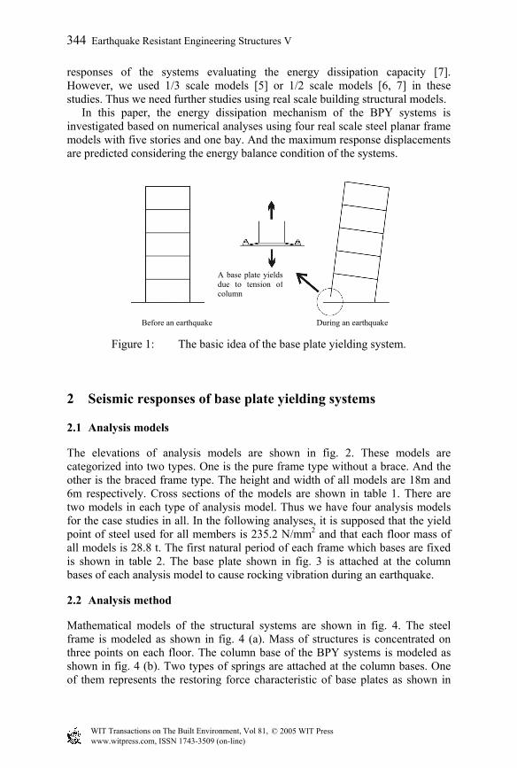
Figure 1: The basic idea of the base plate yielding system.
2 Seismic responses of base plate yielding systems
2.1 Analysis models
The elevations of analysis models are shown in fig. 2. These models are categorized into two types. One is the pure frame type without a brace. And the other is the braced frame type. The height and width of all models are 18m and 6m respectively. Cross sections of the models are shown in table 1. There are two models in each type of analysis model. Thus we have four analysis models for the case studies in all. In the following analyses, it is supposed that the yield point of steel used for all members is 235.2 N/mm2 and that each floor mass of all models is 28.8 t. The first natural period of each frame which bases are fixed is shown in table 2. The base plate shown in fig. 3 is attached at the column bases of each analysis model to cause rocking vibration during an earthquake.
2.2 Analysis method
Mathematical models of the structural systems are shown in fig. 4. The steel frame is modeled as shown in fig. 4 (a). Mass of structures is concentrated on three points on each floor. The column base of the BPY systems is modeled as shown in fig. 4 (b). Two types of springs are attached at the column bases. One of them represents the restoring force characteristic of base plates as shown in
Before an earthquake During an earthquake
A base plate yieldsdue to tension ofcolumn
© 2005 WIT Press WIT Transactions on The Built Environment, Vol 81, www.witpress.com, ISSN 1743-3509 (on-line)
344 Earthquake Resistant Engineering Structures V
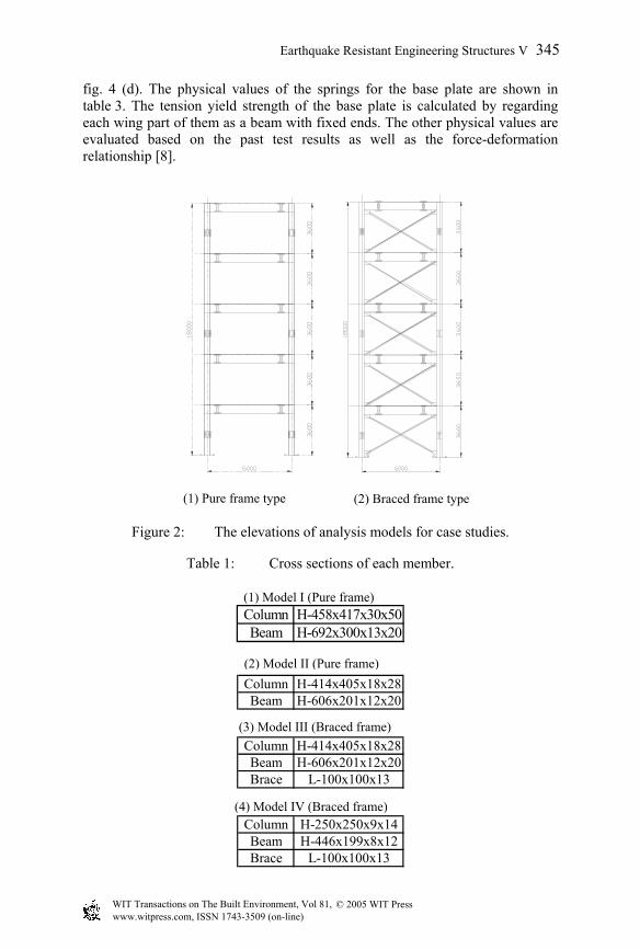
fig. 4 (d). The physical values of the springs for the base plate are shown in table 3. The tension yield strength of the base plate is calculated by regarding each wing part of them as a beam with fixed ends. The other physical values are evaluated based on the past test results as well as the force-deformation relationship [8].
Figure 2: The elevations of analysis models for case studies.
Table 1: Cross sections of each member.
(1) Pure frame type (2) Braced frame type
(1) Model I (Pure frame)Column H-458x417x30x50Beam H-692x300x13x20
(2) Model II (Pure frame)Column H-414x405x18x28Beam H-606x201x12x20
(3) Model III (Braced frame)Column H-414x405x18x28Beam H-606x201x12x20Brace L-100x100x13
(4) Model IV (Braced frame)Column H-250x250x9x14Beam H-446x199x8x12Brace L-100x100x13
© 2005 WIT Press WIT Transactions on The Built Environment, Vol 81, www.witpress.com, ISSN 1743-3509 (on-line)
Earthquake Resistant Engineering Structures V 345
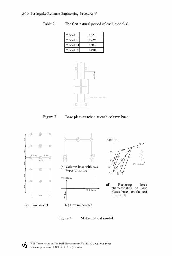
Table 2: The first natural period of each model(s).
Figure 3: Base plate attached at each column base.
Figure 4: Mathematical model.
(a) Frame model
(b) Column base with twotypes of spring
(d) Restoring forcecharacteristics of baseplates based on the testresults [8]
(c) Ground contact
3600
3600
3600
3600
3600
6000
0.67 Wi
0.17 Wi 0.17 Wi
dy
K1
K2
Ny
-Ny
Uplift force
Uplift disp.
1 2
3
4
5
6
7
8
9
10
11
12
13
Uplift force
Uplift disp.
Model I 0.523Model II 0.729Model III 0.384Model IV 0.490
© 2005 WIT Press WIT Transactions on The Built Environment, Vol 81, www.witpress.com, ISSN 1743-3509 (on-line)
346 Earthquake Resistant Engineering Structures V
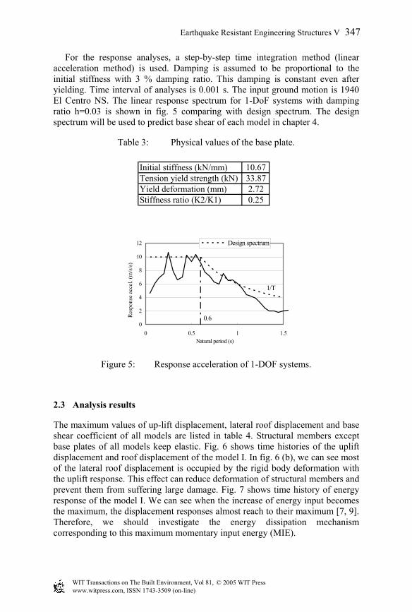
For the response analyses, a step-by-step time integration method (linear acceleration method) is used. Damping is assumed to be proportional to the initial stiffness with 3 % damping ratio. This damping is constant even after yielding. Time interval of analyses is 0.001 s. The input ground motion is 1940 El Centro NS. The linear response spectrum for 1-DoF systems with damping ratio h=0.03 is shown in fig. 5 comparing with design spectrum. The design spectrum will be used to predict base shear of each model in chapter 4.
Table 3: Physical values of the base plate.
Figure 5: Response acceleration of 1-DOF systems.
2.3 Analysis results
The maximum values of up-lift displacement, lateral roof displacement and base shear coefficient of all models are listed in table 4. Structural members except base plates of all models keep elastic. Fig. 6 shows time histories of the uplift displacement and roof displacement of the model I. In fig. 6 (b), we can see most of the lateral roof displacement is occupied by the rigid body deformation with the uplift response. This effect can reduce deformation of structural members and prevent them from suffering large damage. Fig. 7 shows time history of energy response of the model I. We can see when the increase of energy input becomes the maximum, the displacement responses almost reach to their maximum [7, 9]. Therefore, we should investigate the energy dissipation mechanism corresponding to this maximum momentary input energy (MIE).
Initial stiffness (kN/mm) 10.67Tension yield strength (kN) 33.87Yield deformation (mm) 2.72Stiffness ratio (K2/K1) 0.25
0
2
4
6
8
10
12
0 0.5 1 1.5Natural period (s)
Resp
onse
acc
el. (
m/s/
s)
Design spectrum
1/T
0.6
© 2005 WIT Press WIT Transactions on The Built Environment, Vol 81, www.witpress.com, ISSN 1743-3509 (on-line)
Earthquake Resistant Engineering Structures V 347
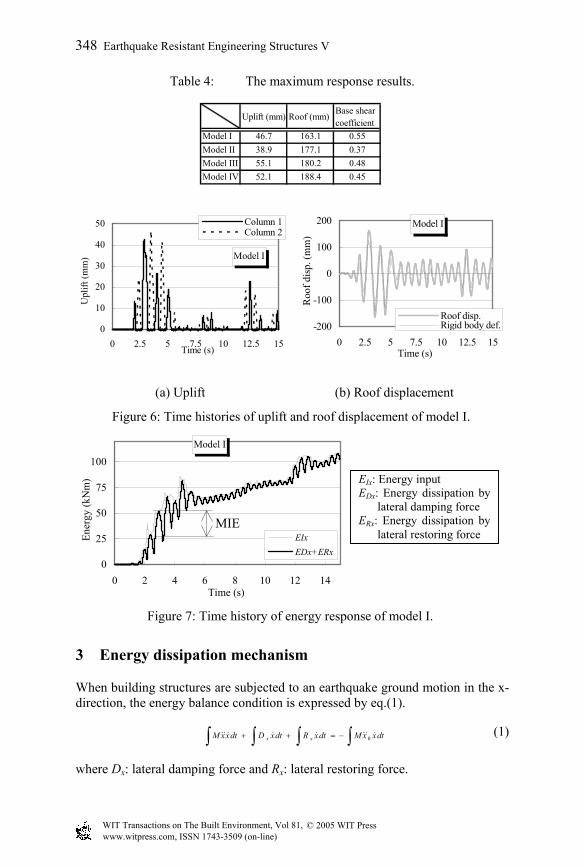
Table 4: The maximum response results.
3 Energy dissipation mechanism
When building structures are subjected to an earthquake ground motion in the x-direction, the energy balance condition is expressed by eq.(1).
∫∫∫∫ −=++ dtxxMdtxRdtxDdtxxM xx 0 (1)
where Dx: lateral damping force and Rx: lateral restoring force.
Figure 6: Time histories of uplift and roof displacement of model I.
(a) Uplift (b) Roof displacement
Figure 7: Time history of energy response of model I.
Uplift (mm) Roof (mm)Base shearcoefficient
Model I 46.7 163.1 0.55Model II 38.9 177.1 0.37Model III 55.1 180.2 0.48Model IV 52.1 188.4 0.45
Model I
0
10
20
30
40
50
0 2.5 5 7.5 10 12.5 15Time (s)
Upl
ift (m
m)
Column 1Column 2
Model I
-200
-100
0
100
200
0 2.5 5 7.5 10 12.5 15Time (s)
Roo
f dis
p. (m
m)
Roof disp.Rigid body def.
Model I
0
25
50
75
100
0 2 4 6 8 10 12 14Time (s)
Ener
gy (k
Nm
)
EIxEDx+ERx
MIE
EIx: Energy input EDx: Energy dissipation by
lateral damping force ERx: Energy dissipation by
lateral restoring force
© 2005 WIT Press WIT Transactions on The Built Environment, Vol 81, www.witpress.com, ISSN 1743-3509 (on-line)
348 Earthquake Resistant Engineering Structures V
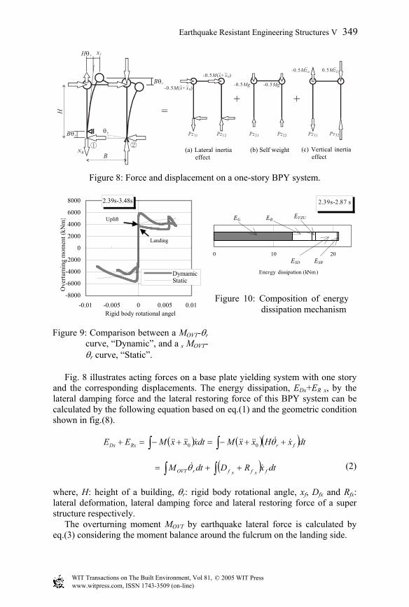
Fig. 8 illustrates acting forces on a base plate yielding system with one story and the corresponding displacements. The energy dissipation, EDx+ER x, by the lateral damping force and the lateral restoring force of this BPY system can be calculated by the following equation based on eq.(1) and the geometric condition shown in fig.(8).
( ) ( )( )dtxHxxMdtxxxMEE frRxDx ∫∫ ++−=+−=+ θ00
( ) dtxRDdtM fxfxfrOVT ∫∫ ++= θ (2)
where, H: height of a building, θr: rigid body rotational angle, xf, Dfx and Rfx: lateral deformation, lateral damping force and lateral restoring force of a super structure respectively. The overturning moment MOVT by earthquake lateral force is calculated by eq.(3) considering the moment balance around the fulcrum on the landing side.
B
xf
②①
- Mg0.5 - Mg0.5
Pz12Pz11 Pz21 Pz22 Pz31 Pz32
- Mz0.5 u・・ 0.5MzL
・・
H
NB
=+ +
θr
Hθ r
Bθr
Bθr
- M x+0.5 ( x0)・・ ・・
- M x+0.5 ( x0)・・ ・・
Figure 8: Force and displacement on a one-story BPY system.
Figure 9: Comparison between a MOVT-θrcurve, “Dynamic”, and a s MOVT-θr curve, “Static”.
(a) Lateral inertiaeffect
(b) Self weight (c) Vertical inertia effect
2.39s-3.48s
-8000
-6000
-4000
-2000
0
2000
4000
6000
8000
-0.01 -0.005 0 0.005 0.01Rigid body rotational angel
Ove
rturn
ing
mom
ent (
kNm
)
DymamicStatic
Uplift
Landing
Figure 10: Composition of energydissipation mechanism
2.39s-2.87 s
0 10 20
Energy dissipation (kNm)
EG EB EVZU
ESD ESR
© 2005 WIT Press WIT Transactions on The Built Environment, Vol 81, www.witpress.com, ISSN 1743-3509 (on-line)
Earthquake Resistant Engineering Structures V 349
( )BNMBMgHxxMM BrOVT ++=+−= θ5.05.0)( 0 (3)
where, B: width of a building, NB: tensile resistance force of base plates. In eq.(3), P-∆ effect and viscous damping of base plates are neglected. Substitution of eq.(3) into eq.(2) yields eq.(4).
dtxFdtxDdtBNdtMBdtMgBEE fxffxfrBrrrRxDx ∫∫∫∫∫ ++++=+ θθθθ 25.05.0
SRSDBVZUG EEEEE ++++= (4)
where, EG: potential energy of self weight, EVZU: kinetic energy by uplift motion, EB: energy dissipation by hysteresis damping of base plates and ESD and ESR: energy dissipation by viscous damping and stress energy of the super structure respectively. Obviously, eq.(4) can be also applied to the multi-story BPY systems. Eqs.(2)-(4) mean the summation of EG, EVZU and EB is represented as area of the figure surrounded with a relationship curve between overturning moments and rigid body rotational angles (MOVT-θr curve). To investigate the effect of vertical inertia force, the MOVT-θr curve of the model I is compared with the corresponding static sMOVT-θr curve in fig 9. These curves are observed during 2.39-3.48 s including duration when the MIE is input. The corresponding static overturning moment sMOVT is calculated by eq.(5), where the vertical inertia force is ignored.
( )BNMgM BOVTS += 5.0 (5)
The difference between the area of MOVT-θr curve and that of sMOVT-θr curve reveals the kinetic energy EVZU by the uplift motion. This difference becomes larger just after the system starts uplifting and just before the system lands. But the former difference is cancelled as the uplifting becomes larger, because the kinetic energy by the uplifting motion is obviously 0 when the uplifting becomes the maximum. On the other hand, the latter difference is accumulated gradually as the system repeats uplifting. This is the impact effect. Fig. 10 shows the composition of energy dissipation corresponding to the MIE. The summation of EG and EB occupy the most part of the energy dissipation with about 80% ratio.
4 Earthquake response prediction
Based on the energy balance condition while the MIE is being input, the maximum uplift displacement of each model is predicted. The MIE is evaluated by response analyses of elastic one-mass systems with 10% viscous damping ratio and various natural periods [9]. For the corresponding energy dissipation, only the summation of ∆EG and ∆EB is estimated, because these energies occupy the most of energy dissipation as shown in fig 10.
© 2005 WIT Press WIT Transactions on The Built Environment, Vol 81, www.witpress.com, ISSN 1743-3509 (on-line)
350 Earthquake Resistant Engineering Structures V

∆EG is calculated by eq.(6).
( )BMgE rrG (max)(max)5.0 αθθ −=∆ (6)
where α: amplification ratio [9], which is judged from displacement responses (in this case, about 0.6). Considering the force-deformation relationships of base plates shown in fig. 11, ∆EB is evaluated by eq.(7). Both EG and EB can be evaluated using the maximum rigid body angle θr(max).
][][ (max)2(max)1 rBrBB EEE θθ ∆+∆=∆ (7)
where ∆EB1[θr(max)] and ∆EB2[θr(max)]: energy dissipation by base plates on the uplift side and the landing side respectively. Fig. 12 shows the MIE spectra comparing with ED curves of each model which shows the relation between the equivalent natural period and the energy dissipation. The equivalent natural period TE is calculated by the following equation [9]. If an arbitrary θr(max) is given, we can calculate TE and the corresponding energy dissipation using it.
EUxE KMT π275.0 ×≈ (8)
dy
K1
K2
Ny
-Ny
Uplift force
Uplift disp.
(+)
(-)
dy
K1
K2
Ny
-Ny
Uplift force
Uplift disp.
(+)
(-)
(a) Uplift side
(b) Landing side
Figure 11: Energy dissipationby base plate.
Figure 12: Comparison between MIE spectrum and ED curve.
0
10
20
30
0 0.5 1 1.5Natural period (s)
MIE
& E
D (k
Nm
)
MIE spectrum
Model III
Model II
Model I
Model IV
© 2005 WIT Press WIT Transactions on The Built Environment, Vol 81, www.witpress.com, ISSN 1743-3509 (on-line)
Earthquake Resistant Engineering Structures V 351
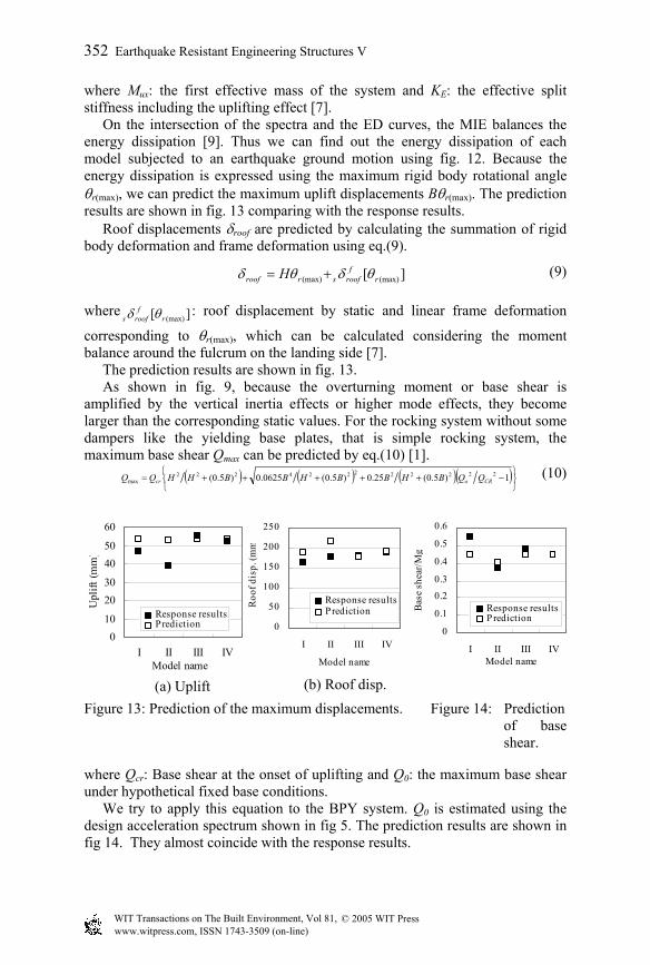
where Mux: the first effective mass of the system and KE: the effective split stiffness including the uplifting effect [7]. On the intersection of the spectra and the ED curves, the MIE balances the energy dissipation [9]. Thus we can find out the energy dissipation of each model subjected to an earthquake ground motion using fig. 12. Because the energy dissipation is expressed using the maximum rigid body rotational angle θr(max), we can predict the maximum uplift displacements Bθr(max). The prediction results are shown in fig. 13 comparing with the response results. Roof displacements δroof are predicted by calculating the summation of rigid body deformation and frame deformation using eq.(9).
][ (max)(max) rf
roofsrroof H θδθδ += (9)
where ][ (max)rf
roofs θδ : roof displacement by static and linear frame deformation
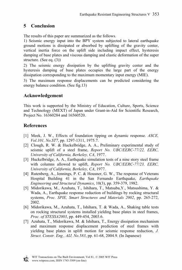
corresponding to θr(max), which can be calculated considering the moment balance around the fulcrum on the landing side [7]. The prediction results are shown in fig. 13. As shown in fig. 9, because the overturning moment or base shear is amplified by the vertical inertia effects or higher mode effects, they become larger than the corresponding static values. For the rocking system without some dampers like the yielding base plates, that is simple rocking system, the maximum base shear Qmax can be predicted by eq.(10) [1].
( ) ( ) ( )( )
−+++++= 1)5.0(25.0)5.0(0625.0)5.0( 222222224222max CRocr QQBHBBHBBHHQQ (10)
Figure 13: Prediction of the maximum displacements. Figure 14: Prediction of base shear.
where Qcr: Base shear at the onset of uplifting and Q0: the maximum base shear under hypothetical fixed base conditions. We try to apply this equation to the BPY system. Q0 is estimated using the design acceleration spectrum shown in fig 5. The prediction results are shown in fig 14. They almost coincide with the response results.
(a) Uplift (b) Roof disp.
010
2030
4050
60
I II III IVModel name
Upl
ift (m
m)
Response resultsPrediction 0
50
100
150
200
250
I II III IV
Model name
Roo
f dis
p. (m
m
Response resultsPrediction
0
0.1
0.2
0.3
0.4
0.5
0.6
I II III IVModel name
Bas
e sh
ear/
Mg
Response resultsPrediction
© 2005 WIT Press WIT Transactions on The Built Environment, Vol 81, www.witpress.com, ISSN 1743-3509 (on-line)
352 Earthquake Resistant Engineering Structures V
5 Conclusion
The results of this paper are summarized as the follows. 1) Seismic energy input into the BPY system subjected to lateral earthquake ground motions is dissipated or absorbed by uplifting of the gravity center, vertical inertia force on the uplift side including impact effect, hysteresis damping of base plates and viscous damping and elastic deformation of the super structure. (See eq. (3)) 2) The seismic energy dissipation by the uplifting gravity center and the hysteresis damping of base plates occupies the large part of the energy dissipation corresponding to the maximum momentary input energy (MIE). 3) The maximum response displacements can be predicted considering the energy balance condition. (See fig.13)
Acknowledgement
This work is supported by the Ministry of Education, Culture, Sports, Science and Technology (MEXT) of Japan under Grant-in-Aid for Scientific Research, Project No. 16360284 and 16560520.
References
[1] Meek, J. W., Effects of foundation tipping on dynamic response. ASCE, Vol.101, No.ST7, pp. 1297-1311, 1975.7.
[2] Clough, R. W. & Huckelbridge, A. A., Preliminary experimental study of seismic uplift of a steel frame, Report No. UBC/EERC-77/22, EERC, University of California, Berkeley, CA, 1977.
[3] Huckelbridge, A. A., Earthquake simulation tests of a nine story steel frame with columns allowed to uplift, Report No. UBC/EERC-77/23, EERC, University of California, Berkeley, CA, 1977.
[4] Rutenberg, A., Jennings, P. C. & Housner, G. W., The response of Veterans Hospital Building 41 in the San Fernando Earthquake, Earthquake Engineering and Structural Dynamics, 10(3), pp. 359-379, 1982.
[5] Midorikawa, M., Azuhata, T., Ishihara, T., Matsuba,Y., Matsushima, Y. & Wada, A., Earthquake response reduction of buildings by rocking structural systems, Proc. SPIE, Smart Structures and Materials 2002, pp. 265-272, 2002.
[6] Midorikawa, M., Azuhata, T., Ishihara, T. & Wada, A., Shaking table tests on rocking structural systems installed yielding base plates in steel frames, Proc. of STESSA2003, pp. 449-454, 2003.6.
[7] Azuhata, T., Midorikawa, M. & Ishihara, T., Energy dissipation mechanism and maximum response displacement prediction of steel frames with yielding base plates in uplift motion for seismic response reduction, J. Struct. Constr. Eng., AIJ, No.583, pp. 61-68, 2004.9. (In Japanese)
© 2005 WIT Press WIT Transactions on The Built Environment, Vol 81, www.witpress.com, ISSN 1743-3509 (on-line)
Earthquake Resistant Engineering Structures V 353

[8] Ishihara, T., Midorikawa, M., Azuhata, T. & Wada, A., Hysteresis characteristics of column base for rocking structural systems with base plate yielding, Journal of Construction Steel, vol. 11, pp. 51-56, 2003.11. (In Japanese)
[9] Nakamura, T., Hori, N. & Inoue, N., Evaluation of damage properties of ground motions and estimation of maximum displacement base on momentary input energy, J. Struct. Constr. Eng., AIJ, No.513, pp. 65-72, 1998.11. (In Japanese)
© 2005 WIT Press WIT Transactions on The Built Environment, Vol 81, www.witpress.com, ISSN 1743-3509 (on-line)
354 Earthquake Resistant Engineering Structures V