Overview of the RISP Superconducting Linac
28
RISP Overview of the RISP Superconducting Linac Dong-O Jeon The Rare Isotope Science Project Institute for Basic Science
Transcript of Overview of the RISP Superconducting Linac

RISP
Overview of the RISP Superconducting Linac
Dong-O Jeon
The Rare Isotope Science Project
Institute for Basic Science

RISP Concept of the Accelerator Complex
Driver Linac
Future Extension
200 MeV/u (U),
8 pμA
Stripper
18 MeV/u
SCL RFQ SCL
28 GHz
SC ECR
IS
H2+, D+
Spallation,
Fission Target
RF Cooler
Mass
Separator
Post Linac
ECR IS
SCL RFQ
Charge Breeder
10 keV/u
Nuclear Data
Low Energy Experiments
0.3 MeV/u 1~5 MeV/u 18 MeV/u
High Energy
Experiments
μSR
Medical
Research
400 kW
Target
Fragment
Separator
Atomic Trap
Experiments
70 kW
Cyclotron
Gas
Catcher,
Gas cell
Material
Science Beta-NMR
U33+
Nuclear Astrophysics
Material science, Bio science
Medical science, Nuclear data
Atomic / Nuclear
physics Nuclear Physics
Medical science
Material science
Material science
SC Linac 200MeV/u for 238U, 600 MeV for p IF driver, high power ISOL driver
Cyclotron 70 MeV, 1mA for p ISOL driver
SC Linac ISOL post accelerator 18 MeV/u

RISP RISP Site Plan
SCL

RISP Bird’s Eye View

RISP Driver SC Linac Lattice Change
5
1 m
QWR1SC Cavity
Focusing solenoids
QWR2
HWR1
HWR1
NC quadrupole
Previous Driver SCL Design with SC solenoids
Driver SCL with NC doublets
SC cavity QWR
• Linac base frequency = 81.25 MHz
• Design to accelerate high intensity ion beams
• Flexile operation to meet the needs of various user groups
beam box
HWR

RISP SCL Design
1 QWR + 1 QD
3 HWR + 1 QD
4 HWR + 1 QD
4 SSR + 1 QD
SCL Cavity
structure Frequency βg
Number of
cavities Output energy
SCL1 QWR 81.25 MHz 0.047 24 2.7 MeV/u (U+33)
HWR 162.5 MHz 0.12 131 18.6 MeV/u (U+33)
SCL2 SSR 325 MHz 0.3 90 66 MeV/u (U+79)
SSR 325 MHz 0.53 160 200 MeV/u (U+79)
8 SSR + 1 QD
beam box example
(courtesy of SPIRAL2)

RISP Driver SCL Lattice Change
NC quadrupole lattice option has the following merits:
1. Accurate alignment < 150 mm of NC quadrupoles is feasible.
2. Beam quality control is straightforward and design is more adequate for high power beam operation.
3. Advantages in beam diagnostics and collimation through beam boxes.
4. The linac cost seems to be in error range compared with the SC solenoid option. ( removal of costly SC solenoids)
5. Preliminary cryo-load comparison suggests that overall cryo-load difference is small compared with the dynamic load.
6. Linac length decrease : 97 m 90 m for the SCL 1, compared with the previous design.
RISP Beam Simulations in SCL1
(b1 + b2) Hyung Jin Kim
xrms yrms DW/Wrms
4ex 4ey 4ez

RISP Phase advance in the SCL1 (b1 + b2)
Hyung Jin Kim
s / m s / period
a b

RISP Beam Simulations in SCL2
(β3 +β4)

RISP Phase Advance in SCL2
(β3 +β4)

RISP Beam Simulations in SCL2
(β3 +β4)
β3 section entrance
- 18.5 MeV/u
- five charge States (77,78,79,80,81)
β3 section exit - 66 MeV/u - five charge states (77,78,79,80,81) - matched to β4

RISP Beam Simulations in SCL2
(β3 +β4)
β4 section entrance
- 66 MeV/u
- five charge states (77,78,79,80,81)
β4 section exit - 200 MeV/u - five charge states (77,78,79,80,81)

RISP
Machine Imperfections
Parameters SCRF
Cavity
Warm
Quadrupole
SC
Solenoid
Distribution
Displacement (mm) ±1 ±0.15 ±0.5 Uniform
Rotation (mrad) - ±5 - Uniform
Phase (deg) ±1 - - 3σ Gaussian
Amplitude (%) ±1 - - 3σ Gaussian
Hyung Jin Kim
• For actual accelerators, certain imperfections are unavoidable due to engineering/alignment imperfections.
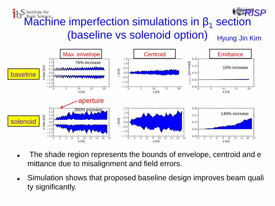
RISP Machine imperfection simulations in β1 section
(baseline vs solenoid option)
Max. envelope Centroid Emittance
baseline
solenoid
10% increase
140% increase
76% increase
350% increase
The shade region represents the bounds of envelope, centroid and e
mittance due to misalignment and field errors.
Simulation shows that proposed baseline design improves beam quali
ty significantly.
Hyung Jin Kim
aperture

RISP Cavity type and optimization
16
QWR HWR
SSR1
SSR2
For U beam
before after
QWR 0.041 QWR 0.047
QWR 0.085 HWR 0.120
HWR 0.285 SSR 0.300
HWR 0.530 SSR 0.530
Cavity types are changed for high intensity, high power beam operation.
Cavity geometry is optimized for all four types of the SC cavities.

RISP Cavity Geometry Optimization (dimensions are in cm)
rdo
g
liris
d
α 2r
h
2R
hb
2r1
rd
Parameter value
h 69.6
r 4
R 11
hb 18
r1 2
rdo 7
rd 7
liris 10.48
g 2.54
d 7.94
Ez Eabs Habs Habs
The geometry of the quarter wave resonator is optimized.

RISP Summary of optimized HWR
parameter value
r, mm 48.5
R, mm 120
d, mm 107.8
lint, mm 136
g, mm 35
rdt , mm 60
rs , mm 60
r1 , mm 20
h, mm 910.38
Eabs Habs
2r
h
2R
2r1
rs rdt
g
lint
d
Ez
The geometry of the half wave resonator is optimized.

RISP
parameter SSR1 SSR2
h, mm 85 120
L_iris, mm 190 330
T, mm 55 115
L_cav, mm 339 510
D, mm 169 238
V, mm 93 95
w, mm 100 180
R, mm 250 265
Liris
R
V
Lcav
T
D
h
W
R
beam
Summary of optimized SSR’s
Ez Habs Ez Ez Habs
Habs

RISP
Eacc = Vacc / (bl)
Cavity Parameters Driver SCL load = 2.1 kW, ISOL SCL load = 0.33 kW Parameters Unit QWR HWR SSR 1 SSR 2
bg - 0.047 0.12 0.30 0.53
Resonant frequency MHz 81.25 162.5 325 325
No of cavities - 24 131 90 160
Aperture diameter mm 40 40 50 50
QRs Ohm 17.5 41.2 86.1 104.7
R/Q Ohm 472.3 264.8 237.0 298.0
Vacc MV 1.02 1.07 2.04 3.53
Epeak MV/m 30 30 30 30
Bpeak mT 54.1 40.8 52.2 62.3
Epeak/Eacc 5.08 6.2 4.06 4.15
Bpeak/Eacc 9.16 8.4 7.07 8.6
Qcalc/109 - 1.8 4.0 8.1 9.1
Operating temperature K 2 2 2 2
P0 W 2.7 2.0 4.8 8.4
Pbeam / emA (proton) W 854 925 1440 2770
Pbeam / emA (Uranium) W 113 134 524 926
Beam current (Uranium) pmA 9.5 9.5 8 8
Average charge state (U) - 33.5 33.5 79 79

RISP
ISOL post-accelerator
• For the ISOL SCL lattice, we are planning to share the same doublet lattice as the driver SCL to reduce cost and required R&D efforts.
• EBIS is considered rather than ECR IS, generating higher charge state beams.
• Design optimized for A/q ≤ 8.

RISP Charge Stripper
• Previously carbon foil was considered as the charge stripper.
• We are designing the charge stripper section to accommodate liquid Li or He gas charge stripper.
Courtesy of FRIB

RISP Stripping Station Conceptual Design
• Change from 180º chicane to 90º bend.
• Conforms better to the topography of the site.
• Shorter in length better control in longitudinal plane.
• Better in radiation activation control for the downstream section.
• Various Charge Strippers are under study.

RISP Present Charge Stripping Section
90° bend Hye-Jin Kim

RISP Temp SRF Test Facility
• A contingency plan for the temporary Superconducting RF and Magnet Test Facility is being developed, considering a possible delay in procuring the site.
• Plan and cost estimation are developed.
• Cost is 2856 M KRW (= $2.4 M) for SRF Facility and 1200 M KRW for Magnet Test Facility (20m x 20m)

RISP Summary
• Base frequency of the SCL is determined.
• For the SCL, NC quadrupole lattice is adopted rather than the SC solenoid:
- Better beam quality control
- Beam diagnostics and collimation advantages
• Same design for the ISOL post-linac.
• Cavity types and geometric betas are determined.
• Cavity geometry is being optimized.
RISP Summary
• Construction of the Superconducting RF Test Facility is under way.
• International Collaboration is an essential part for the success of the project.

RISP Thanks for your attention!
To the goal, Cheers!!